EP3531179A1 - Optical fiber distribution system - Google Patents
Optical fiber distribution system Download PDFInfo
- Publication number
- EP3531179A1 EP3531179A1 EP19167992.7A EP19167992A EP3531179A1 EP 3531179 A1 EP3531179 A1 EP 3531179A1 EP 19167992 A EP19167992 A EP 19167992A EP 3531179 A1 EP3531179 A1 EP 3531179A1
- Authority
- EP
- European Patent Office
- Prior art keywords
- telecommunications
- chassis
- telecommunications chassis
- release handle
- locking spring
- Prior art date
- Legal status (The legal status is an assumption and is not a legal conclusion. Google has not performed a legal analysis and makes no representation as to the accuracy of the status listed.)
- Granted
Links
Images























Classifications
-
- G—PHYSICS
- G02—OPTICS
- G02B—OPTICAL ELEMENTS, SYSTEMS OR APPARATUS
- G02B6/00—Light guides; Structural details of arrangements comprising light guides and other optical elements, e.g. couplings
- G02B6/44—Mechanical structures for providing tensile strength and external protection for fibres, e.g. optical transmission cables
- G02B6/4439—Auxiliary devices
- G02B6/444—Systems or boxes with surplus lengths
- G02B6/4453—Cassettes
- G02B6/4455—Cassettes characterised by the way of extraction or insertion of the cassette in the distribution frame, e.g. pivoting, sliding, rotating or gliding
-
- F—MECHANICAL ENGINEERING; LIGHTING; HEATING; WEAPONS; BLASTING
- F16—ENGINEERING ELEMENTS AND UNITS; GENERAL MEASURES FOR PRODUCING AND MAINTAINING EFFECTIVE FUNCTIONING OF MACHINES OR INSTALLATIONS; THERMAL INSULATION IN GENERAL
- F16M—FRAMES, CASINGS OR BEDS OF ENGINES, MACHINES OR APPARATUS, NOT SPECIFIC TO ENGINES, MACHINES OR APPARATUS PROVIDED FOR ELSEWHERE; STANDS; SUPPORTS
- F16M13/00—Other supports for positioning apparatus or articles; Means for steadying hand-held apparatus or articles
- F16M13/02—Other supports for positioning apparatus or articles; Means for steadying hand-held apparatus or articles for supporting on, or attaching to, an object, e.g. tree, gate, window-frame, cycle
-
- G—PHYSICS
- G02—OPTICS
- G02B—OPTICAL ELEMENTS, SYSTEMS OR APPARATUS
- G02B6/00—Light guides; Structural details of arrangements comprising light guides and other optical elements, e.g. couplings
- G02B6/44—Mechanical structures for providing tensile strength and external protection for fibres, e.g. optical transmission cables
-
- G—PHYSICS
- G02—OPTICS
- G02B—OPTICAL ELEMENTS, SYSTEMS OR APPARATUS
- G02B6/00—Light guides; Structural details of arrangements comprising light guides and other optical elements, e.g. couplings
- G02B6/44—Mechanical structures for providing tensile strength and external protection for fibres, e.g. optical transmission cables
- G02B6/4439—Auxiliary devices
- G02B6/444—Systems or boxes with surplus lengths
- G02B6/4452—Distribution frames
- G02B6/44526—Panels or rackmounts covering a whole width of the frame or rack
-
- G—PHYSICS
- G02—OPTICS
- G02B—OPTICAL ELEMENTS, SYSTEMS OR APPARATUS
- G02B6/00—Light guides; Structural details of arrangements comprising light guides and other optical elements, e.g. couplings
- G02B6/44—Mechanical structures for providing tensile strength and external protection for fibres, e.g. optical transmission cables
- G02B6/4439—Auxiliary devices
- G02B6/444—Systems or boxes with surplus lengths
- G02B6/44528—Patch-cords; Connector arrangements in the system or in the box
-
- B—PERFORMING OPERATIONS; TRANSPORTING
- B29—WORKING OF PLASTICS; WORKING OF SUBSTANCES IN A PLASTIC STATE IN GENERAL
- B29L—INDEXING SCHEME ASSOCIATED WITH SUBCLASS B29C, RELATING TO PARTICULAR ARTICLES
- B29L2031/00—Other particular articles
- B29L2031/775—Toothed articles
- B29L2031/7752—Racks
Definitions
- the present invention relates to an optical fiber distribution system, including a rack, and elements which populate the rack, including fiber terminations, patching, fiber splitters, and fiber splices.
- Optical fiber distribution systems include fiber terminations and other equipment which is typically rack mounted.
- One implementation of a system in accordance with the examples of the disclosure includes a building block element mountable to a rack or other structure.
- the element includes a chassis and a movable tray.
- the tray is movably mounted to chassis with a slide mechanism that allows the tray to slide relative to the chassis.
- the slide mechanism includes a synchronized movement feature for managing the cables extending to and from the tray, such that cable pull at the entry and exit locations is reduced or eliminated as the tray is moved.
- One synchronized movement feature includes gears, including a rack and pinion system
- Another synchronized movement feature includes wheels and wires.
- the tray preferably includes mounting structures for holding cable terminations, splitters, and/or splices.
- One mounting structure includes an open shaped frame member for connector access.
- two frame members are provided, one positioned over the other.
- the frame members are hingedly mounted to the tray.
- the adapters are arranged so that the connector axes are horizontal and extend in a perpendicular direction to the direction of travel for the tray.
- Each frame member can be populated with adapter blocks.
- Pathways guide cables to the adapter ports of the adapter blocks for fiber optic cables terminated with connectors to be received therein.
- the cables follow a general S-shaped pathway from a side of each element to the adapter blocks.
- the S-shaped pathway includes two levels inside of the tray to segregate cables between the two frame members.
- Various flanges and radius limiters can be provided to assist with cable management.
- the elements can be stacked in a column with each tray mounted horizontally, or used in a group or block mounted vertically. In the case of a column of elements, a selected tray is pulled outward to access the desired tray, and then the frame members on the tray can be pivoted as needed.
- each element can be for patch cables, and the opposite side can be for cable termination of an incoming cable, such as a distribution cable or a feeder cable. Because of the synchronized movement feature, cables can be secured along the sides of the elements and still allow for sliding movement of the trays without a need for large amounts or any cable slack.
- the tray and the frame members allow for easy top and bottom access to connectors on either side of the adapters. Openings are provided in the tray bottom for hand access if desired.
- the cable mounts for the distribution cables or feeder cables can be snap mounted to the elements and/or mounted in a longitudinal slide mount, and include strength member clamps and cable clamps.
- Groupings of loose cables can be managed with cable wraps or other cable guides such as flexible troughs.
- the elements can be configured as desired and form building blocks for an optical fiber distribution system (ODF).
- ODF optical fiber distribution system
- the cables can be placed in vertical cable guides to enter and exit the selected element.
- the example rack is front accessible, however, the elements can be used in other racks, frames, cabinets or boxes including in arrangements where rear access is desirable or useful.
- the disclosure is directed to a universal mounting mechanism configured for mounting a telecommunications chassis to a telecommunications fixture, the mounting mechanism comprising a mounting bracket defining a rear portion configured for mounting to the telecommunications fixture and a front portion configured to slidably receive the telecommunications chassis, the front portion including a latch opening, a locking spring configured to be mounted to the telecommunications chassis, the locking spring defining a portion configured to flex laterally to snap in to the latch opening, a release handle configured to be slidably mounted to the telecommunications chassis, the release handle defining a deflection tab for moving the locking spring out of the latch opening of the mounting bracket when the release handle is slid along a rearward to forward direction with respect to the telecommunications chassis, and a cover configured to be mounted to the telecommunications chassis, the cover defining a deflection ramp configured to interact with the deflection tab of the release handle for moving the deflection tab laterally to contact the locking spring when the release handle is
- the disclosure is directed to a telecommunications system that includes the universal mounting bracket mounted between the telecommunications chassis and the telecommunications fixture.
- the disclosure is directed to a method of releasably mounting a telecommunications chassis to a telecommunications rack.
- the method comprises mounting a mounting bracket to the telecommunications fixture, the mounting bracket defining a front portion including a latch opening, sliding the front portion of the mounting bracket into a bracket channel defined on at least one side of the telecommunications chassis, laterally flexing a locking spring to snap-fit at least a portion of the locking spring into the latch opening, and pulling a release handle on the telecommunications chassis along a rearward to forward direction to deflect the locking spring out of the latch opening.
- an optical fiber distribution element 10 or element 10
- the elements 10 can be individually mounted as desired to telecommunications equipment including racks, frames, or cabinets.
- the elements 10 can be mounted in groups or blocks 12 which form a stacked arrangement.
- a vertical stack of elements 10 populates an optical fiber distribution rack.
- Each element 10 holds fiber terminations, or other fiber components including fiber splitters and/or fiber splices.
- fiber terminations incoming cables are connected to outgoing cables through connectorized cable ends which are connected by adapters, as will be described below.
- Each element includes a chassis 20 and a movable tray 24.
- Tray 24 is movable with a slide mechanism 30 including one or more gears 32 and a set of two toothed racks or linear members 34.
- Slide mechanism 30 provides for synchronized movement for managing the cables extending to and from tray 24. Entry points 36 on either side of chassis 20 allow for fixation of the input and output cables associated with each element 10.
- the radius limiters 38 associated with each slide mechanism 30 move in synchronized movement relative to chassis 20 and tray 24 to maintain fiber slack, without causing fibers to be bent, pinched, or pulled.
- Each tray 24 includes mounting structure 50 defining one or more fiber terminations, fiber splitters, fiber splices, or other fiber components. As shown, mounting structure 50 holds adapters 52 which allow for interconnection of two connectorized ends of cables.
- Each tray 24 includes one or more frame members 56. In the example shown, two frame members 56 are provided. As illustrated, each frame member 56 is T-shaped. Also, each tray 24 includes two frame members 56 which are hingedly mounted at hinges 58. A top frame member 62 is positioned above a bottom frame member 64.
- the mounting structure 50 associated with each frame member 62, 64 includes one or more integrally formed adapter blocks 70. Adapter blocks 70 include a plurality of adapter ports for interconnecting to fiber optic connectors.
- a pathway 76 defines a generally S-shape from radius limiters 38 to adapter blocks 70. As shown, pathway 76 includes an upper level 78 and a lower level 80 in the interior. A portion 84 of pathway 76 is positioned adjacent to hinges 58 to avoid potentially damaging cable pull during pivoting movement of frame members 56. Flanges 86 and radius limiters 90 help maintain cables in pathways 76.
- Tray 24 includes openings 96 to allow for technician access to the cable terminations at adapter blocks 70.
- the T-shapes of frame members 56 further facilitate technician access to the connectors.
- Cables extending to and from element 10 can be affixed with a cable mount 100 as desired. Additional protection of the fiber breakouts can be handled with cable wraps 102. Radius limiters 106 can be additionally used to support and protect the cables.
- more than one feeder cable can supply cabling to more than one element 10.
- Element 210 includes a chassis 220 in a movable tray 224 mounted with a slide mechanism 230 which promotes synchronized movement of radius limiters 238.
- Each tray 224 includes two hingedly mounted frame members 256.
- Each frame member 256 has a middle portion 260 separated by openings 262 from side portions 264.
- Middle portion 260 can hold fiber terminations.
- Side portions 264 include radius limiters 270.
- Cover 266 goes over tray 224. Latches 268 latch tray 224 to cover 266 in the closed position.
- a pathway 276 extends from either side of tray 224 to supply cables to each of trays 224.
- An upper level 278 and a lower level 280 supply the respective frame members 256 with cabling.
- a general S-shaped pathway 276 is defined wherein the pathway 276 passes close to hinges 258.
- a dovetail 288 is used to hold cable mounts 286 and radius limiters 284.
- An opening 290 in tray 224 allows for connector access by the technician.
- openings 262 on each frame member 256 allow for technician access to the individual connectors.
- Bars 294 give a small spacing between each element 210.
- Slide mechanism 330 allows for movement of the trays and related radius limiters and synchronized movement similar to slide mechanism 30, 230.
- Alternative slide mechanism 330 includes two wheels 332 and two wires 334, 336. The wheels 332 are located on second part 342. The wires are looped in opposite directions and are connected to the first part 340 and the third part 344.
- Radius limiter 420 includes friction members 430 which limit the amount of sliding movement of cables passing through radius limiter 420, to assist with cable management.
- Friction members 430 include flexible fingers which press lightly on the cables in radius limiter 420 to reduce or eliminate sliding movement of the cables in the radius limiter 420.
- a universal mounting mechanism 500 for releasably mounting a telecommunications chassis to a telecommunications fixture, such as an optical fiber distribution rack, is illustrated.
- the universal mounting mechanism 500 is shown as having been adapted for and being used on an optical fiber distribution element 510 having features similar to those elements 210, 410 shown in Figures 30-47 of the present disclosure.
- telecommunications chassis or elements such as elements 210, 410, and 510 can be mounted as desired to telecommunications fixtures or equipment such as racks, frames, or cabinets.
- the universal mounting mechanism 500 of the present disclosure has been shown as being used on a piece of telecommunications equipment such as the optical fiber distribution element 510 (which has similar features to those elements 210 and 410 of Figures 30-47 ), the optical fiber distribution element 510 is simply one example of telecommunications equipment or chassis on which the mounting mechanism 500 may be used for mounting to equipment such as telecommunications racks, frames, or cabinets.
- the element 510 has been adapted to receive certain portions of the mounting mechanism 500.
- the mounting mechanism 500 of the present disclosure includes features having inventive aspects in isolation and can be used on other types of optical fiber distribution elements as long as the elements or chassis thereof are adapted to receive portions of the mounting mechanism 500.
- Figure 48 shows a cross-sectional view of a portion of the universal mounting mechanism 500, wherein the mounting mechanism 500 is in a locked state or position.
- Figure 49 illustrates the universal mounting mechanism 500 in an unlocked position.
- Figure 50 illustrates a partially exploded perspective view of a portion of the universal mounting mechanism 500 being used with the optical fiber distribution element 510, which is similar to the elements 210, 410 shown in Figures 30-47 , as noted above.
- Figure 51 illustrates the universal mounting mechanism 500 with the universal mounting brackets 502 of the mechanism 500 mounted to the element 510.
- Figure 51A is a close-up view of a portion of the universal mounting mechanism 500, illustrating a locking spring 504 of the mechanism 500 in a locked position with respect to the universal mounting bracket 502 of the mechanism 500.
- Figure 52 is a cross-sectional view of a portion of the universal mounting mechanism 500 showing the positional relationship between the universal mounting bracket 502 and a release handle 506 of the mounting mechanism 500 when the mechanism 500 is in a locked state.
- the universal mounting mechanism 500 generally includes the right and left universal mounting brackets 502, release handles 506 for each of the mounting brackets 502, a cover 508 for each of the mounting brackets 502, and the locking spring 504 for each of the mounting brackets 502.
- each of the universal mounting brackets 502 is designed for mounting two stacked elements 510.
- each of the right and left mounting brackets 502 includes two latch openings 512 adjacent the front 514 of the mounting bracket 502 (one for each element 510) and upper and lower mounting tabs 516 at the rear 518 of the bracket 502.
- the mounting tabs 516 at the rear 518 of the mounting brackets 502 are designed to slidably mount the brackets 502 to fixtures such as telecommunications racks along a sideway or lateral direction.
- the universal mounting brackets 502 are initially slid into openings provided on the rack using the mounting tabs 516.
- the elements 510 can be slid onto the brackets 502 in a sliding fashion, as will be described in further detail.
- the latch openings 512 of the brackets 502 are then used to lock the elements 510 in place.
- each element 510 on each of the right and left sides thereof, defines a bracket channel 520.
- the channel 520 is configured to slidably receive the front portions 514 of the mounting brackets 502.
- the cover 508 closes the bracket channel 520 to the exterior of each element 510.
- the cover 508 defines a deflection ramp 522 at the inner face thereof, the purpose of which will be discussed in further detail below.
- the locking spring 504 is mounted to each element 510 such that an end portion 524 of the locking spring 504 can flex in and out of the latch opening 512 of the universal mounting bracket 502.
- the end portion 524 of the locking spring 504 defines a perpendicular locking face 526 and an angular insertion face 528.
- the angled insertion face 528 rides over the front end 530 of the front portion 514 of the mounting bracket 502 until the end portion 524 of the locking spring 504 flexibly snaps into the latch opening 512.
- the element 510 is prevented from being pulled out forwardly.
- the locking spring 504 abuts an inner front face 532 defined by the latch opening 512 of the mounting bracket 502 to prevent removal of the chassis from a rack.
- the release handle 506 is positioned between the locking spring 504 and the cover 508.
- the release handle 506 has a grip portion 534 for pulling the release handle 504 forwardly to release the chassis for removal from the mounting brackets 502.
- the release handle 504 also defines a deflection tab 536 at the rear end 538.
- the deflection tab 536 is configured to ride over the deflection ramp 522 of the cover 508 when the grip portion 534 is pulled forwardly.
- the interaction of the deflection tab 536 and the deflection ramp 522 causes lateral inward movement of the deflection tab 536, which in turn, pushes the spring 504 laterally inwardly, clearing the end portion 524 of the locking spring 504 from the latching opening 512.
- a tray of the element 510 has to be pulled from its chassis to allow enough room for gripping the release handle 506 as seen in Figure 52 , to pull it forwardly.
- the release handle 506 In initially mounting the element 510 to a rack using the universal mounting mechanism 500, the release handle 506 has to be either pushed rearwardly by the user to allow the spring 504 to be positioned in its locking position or the user can simply push a tray of the element 510 rearwardly to contact the grip portion 534 of the release handle 506 to push the release handle 506 rearwardly.
- the release handle 506 when the element 510 is mounted to a rack using the universal mounting mechanism 500, the release handle 506 must be in its rearward position to allow the spring 504 to be in its locking position. Otherwise, if the release handle 506 is in its forward position, the element 510 can simply slide out of the brackets 502.
- the release handle 506 defines a positive stop 540 that is configured to abut a stop face 542 defined by a portion of a slide mechanism 544 within the element 510. The abutment of the stop 540 with the stop face 542 prevents further forward pulling of the release handle 506.
- the universal mounting mechanism 500 includes a design that may be retrofitted on a number of telecommunications chassis. As long as a bracket channel 520 is provided in the chassis and the chassis includes enough spacing on the sides thereof for receiving a locking spring 504, a release handle 506, and a cover 508 for interacting with the release handle 506 and closing the mounting mechanism 500 to the exterior of the chassis, the universal mounting mechanism 500 can be utilized on a given chassis.
- the rear portion 518 of the mounting brackets 502 may be modified to fit different types of mounting configurations on different types of telecommunications racks, frames, or cabinets.
- the mounting arrangement of the brackets 502 of the present disclosure that utilizes the tabs 516 for lateral slide-locking is simply one example of a mounting arrangement.
- the mounting mechanism 500 of the present disclosure has been shown with mounting brackets 502 that can accommodate two vertically stacked elements 510, the mounting brackets 502 can be modified to receive other number of chassis, including a single chassis per bracket 502.
- the locking spring 504 is fixed to the chassis with fasteners 545, allowing the end portion 524 of the locking spring 504 to be flexible.
- Other fixing methods may be used for the locking spring 504 in other types of telecommunications equipment.
Landscapes
- Physics & Mathematics (AREA)
- General Physics & Mathematics (AREA)
- Optics & Photonics (AREA)
- Engineering & Computer Science (AREA)
- General Engineering & Computer Science (AREA)
- Mechanical Engineering (AREA)
- Light Guides In General And Applications Therefor (AREA)
- Casings For Electric Apparatus (AREA)
- Fittings On The Vehicle Exterior For Carrying Loads, And Devices For Holding Or Mounting Articles (AREA)
- Mirrors, Picture Frames, Photograph Stands, And Related Fastening Devices (AREA)
Description
- This application claims priority to
U.S. Provisional Application No. 61/815,549, filed April 24, 2013 - The present invention relates to an optical fiber distribution system, including a rack, and elements which populate the rack, including fiber terminations, patching, fiber splitters, and fiber splices.
- Optical fiber distribution systems include fiber terminations and other equipment which is typically rack mounted. Various concerns exist for the optical fiber distribution systems, including density, ease of use, and cable management. There is a continuing need for improvements in the optical fiber distribution area.
- One implementation of a system in accordance with the examples of the disclosure includes a building block element mountable to a rack or other structure. The element includes a chassis and a movable tray. The tray is movably mounted to chassis with a slide mechanism that allows the tray to slide relative to the chassis. The slide mechanism includes a synchronized movement feature for managing the cables extending to and from the tray, such that cable pull at the entry and exit locations is reduced or eliminated as the tray is moved.
- One synchronized movement feature includes gears, including a rack and pinion system Another synchronized movement feature includes wheels and wires.
- The tray preferably includes mounting structures for holding cable terminations, splitters, and/or splices. One mounting structure includes an open shaped frame member for connector access. In one example, two frame members are provided, one positioned over the other. For improved access, the frame members are hingedly mounted to the tray. In a termination arrangement, the adapters are arranged so that the connector axes are horizontal and extend in a perpendicular direction to the direction of travel for the tray.
- Each frame member can be populated with adapter blocks. Pathways guide cables to the adapter ports of the adapter blocks for fiber optic cables terminated with connectors to be received therein. The cables follow a general S-shaped pathway from a side of each element to the adapter blocks. The S-shaped pathway includes two levels inside of the tray to segregate cables between the two frame members. Various flanges and radius limiters can be provided to assist with cable management.
- The elements can be stacked in a column with each tray mounted horizontally, or used in a group or block mounted vertically. In the case of a column of elements, a selected tray is pulled outward to access the desired tray, and then the frame members on the tray can be pivoted as needed.
- One side of each element can be for patch cables, and the opposite side can be for cable termination of an incoming cable, such as a distribution cable or a feeder cable. Because of the synchronized movement feature, cables can be secured along the sides of the elements and still allow for sliding movement of the trays without a need for large amounts or any cable slack.
- The tray and the frame members allow for easy top and bottom access to connectors on either side of the adapters. Openings are provided in the tray bottom for hand access if desired.
- The cable mounts for the distribution cables or feeder cables can be snap mounted to the elements and/or mounted in a longitudinal slide mount, and include strength member clamps and cable clamps.
- Groupings of loose cables can be managed with cable wraps or other cable guides such as flexible troughs.
- The elements can be configured as desired and form building blocks for an optical fiber distribution system (ODF).
- When the elements are mounted in a column in a rack, the cables can be placed in vertical cable guides to enter and exit the selected element.
- The example rack is front accessible, however, the elements can be used in other racks, frames, cabinets or boxes including in arrangements where rear access is desirable or useful.
- According to another aspect, the disclosure is directed to a universal mounting mechanism configured for mounting a telecommunications chassis to a telecommunications fixture, the mounting mechanism comprising a mounting bracket defining a rear portion configured for mounting to the telecommunications fixture and a front portion configured to slidably receive the telecommunications chassis, the front portion including a latch opening, a locking spring configured to be mounted to the telecommunications chassis, the locking spring defining a portion configured to flex laterally to snap in to the latch opening, a release handle configured to be slidably mounted to the telecommunications chassis, the release handle defining a deflection tab for moving the locking spring out of the latch opening of the mounting bracket when the release handle is slid along a rearward to forward direction with respect to the telecommunications chassis, and a cover configured to be mounted to the telecommunications chassis, the cover defining a deflection ramp configured to interact with the deflection tab of the release handle for moving the deflection tab laterally to contact the locking spring when the release handle is slid with respect to the telecommunications chassis.
- According to another aspect, the disclosure is directed to a telecommunications system that includes the universal mounting bracket mounted between the telecommunications chassis and the telecommunications fixture.
- According to yet another aspect, the disclosure is directed to a method of releasably mounting a telecommunications chassis to a telecommunications rack. The method comprises mounting a mounting bracket to the telecommunications fixture, the mounting bracket defining a front portion including a latch opening, sliding the front portion of the mounting bracket into a bracket channel defined on at least one side of the telecommunications chassis, laterally flexing a locking spring to snap-fit at least a portion of the locking spring into the latch opening, and pulling a release handle on the telecommunications chassis along a rearward to forward direction to deflect the locking spring out of the latch opening.
-
-
Figure 1 is a perspective view of a first embodiment of an optical fiber distribution element in accordance with aspects of the present disclosure; -
Figure 2 is a top view of the element ofFigure 1 ; -
Figure 3 is a perspective view of the element ofFigure 1 showing the tray pulled forward from the chassis; -
Figure 4 shows one of the tray frame members pivoted upwardly from the tray; -
Figure 5 shows a second frame member pivoted upwardly relative to the tray; -
Figure 6 shows a portion of a cable management area of the element ofFigure 1 ; -
Figure 7 shows a similar view toFigure 6 , with one of the frame members pivoted upwardly; -
Figure 8 shows an alternative embodiment of an element with different cable management at the entry points; -
Figure 9 shows three of the elements ofFigure 8 mounted in a block formation, with cable radius limiters at the entry point mounted in an alternative position; -
Figure 10 is a perspective view of the block ofFigure 9 ; -
Figure 11 is a view of the block ofFigure 9 , with the tray of the middle element pulled forward for access to the fiber terminations; -
Figure 12 shows an enlarged portion of an entry point for one of the elements with a cable radius limiter in a first position; -
Figure 13 shows a similar view as inFigure 12 , with the cable radius limiter positioned in an alternate position; -
Figure 14 shows an exploded view of a cable mount; -
Figure 15 shows an element with a cable mount on one side, and a cable radius limiter on an opposite side; -
Figure 16 shows an alternative cable mount; -
Figures 17-29 show various views of the elements shown inFigures 1-16 including additional details and cable routings shown for illustration purposes; -
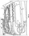
Figure 30 shows an alternative embodiment of a block of two alternative elements; -
Figure 31 shows a tray pulled forward from the chassis of one of the elements of the block ofFigure 30 ; -
Figure 32 shows the tray extended forward as in the view ofFigure 31 , with one of the frame members pivoted upwardly; -
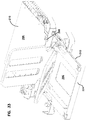
Figure 33 is a view similar to the view ofFigure 32 , with a second frame member pivoted upwardly; -
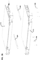
Figure 34 shows a block including two elements; -
Figure 35 shows an exploded view of the two elements of the block ofFigure 34 ; -
Figure 36 shows a single element; -
Figure 37 shows an exploded view of the element ofFigure 36 ; -
Figure 38 shows the element ofFigure 37 , without the top cover; -
Figure 39 is a top view of the element ofFigure 38 ; -
Figure 40 is an alternative view of the element ofFigure 38 , showing alternative devices at the cable entry points; -
Figure 41 is a top view of the element ofFigure 40 ; -
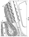
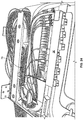
Figure 42 shows an alternative embodiment of an element in a top view with an alternative synchronized movement feature; -
Figure 43 is a perspective view of the element ofFigure 42 ; -
Figures 44 and45 show movement of the various components of the synchronized movement feature ofFigures 42 and43 ; -
Figures 46 and47 show an element with an alternative radius limiter at the cable entry and exit locations; -
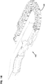
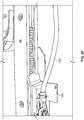
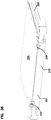
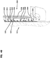
Figure 48 shows a cross-sectional view of a portion of a universal mounting mechanism having features that are examples of inventive aspects of the disclosure, the universal mounting mechanism configured for mounting an optical fiber distribution element similar to those shown inFigures 30-47 of the present disclosure to a telecommunications rack, the mounting mechanism shown in a locked position; -
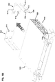
Figure 49 illustrates the universal mounting mechanism ofFigure 48 in an unlocked position; -
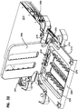
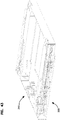
Figure 50 illustrates a partially exploded perspective view of a portion of the universal mounting mechanism ofFigures 48-49 being used on an optical fiber distribution element similar to the elements shown inFigures 30-47 ; -
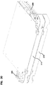
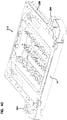
Figure 51 illustrates the universal mounting mechanism ofFigure 50 with the universal mounting brackets of the mechanism mounted to the element ofFigure 50 ; -
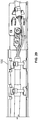
Figure 51A is a close-up view of a portion of the universal mounting mechanism ofFigure 51 , illustrating the locking spring in a locked position with respect to the universal mounting bracket; and -
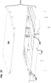
Figure 52 is a cross-sectional view of a portion of the universal mounting mechanism ofFigure 48 showing the positional relationship between the universal mounting bracket and the release handle of the mounting mechanism when the mounting mechanism is in a locked state. - Referring now to
Figures 1-16 , various embodiments of an opticalfiber distribution element 10, orelement 10, are shown. Theelements 10 can be individually mounted as desired to telecommunications equipment including racks, frames, or cabinets. Theelements 10 can be mounted in groups or blocks 12 which form a stacked arrangement. In one embodiment, a vertical stack ofelements 10 populates an optical fiber distribution rack. - Each
element 10 holds fiber terminations, or other fiber components including fiber splitters and/or fiber splices. In the case of fiber terminations, incoming cables are connected to outgoing cables through connectorized cable ends which are connected by adapters, as will be described below. - Each element includes a
chassis 20 and amovable tray 24.Tray 24 is movable with aslide mechanism 30 including one ormore gears 32 and a set of two toothed racks orlinear members 34. -
Slide mechanism 30 provides for synchronized movement for managing the cables extending to and fromtray 24. Entry points 36 on either side ofchassis 20 allow for fixation of the input and output cables associated with eachelement 10. The radius limiters 38 associated with eachslide mechanism 30 move in synchronized movement relative tochassis 20 andtray 24 to maintain fiber slack, without causing fibers to be bent, pinched, or pulled. - Each
tray 24 includes mountingstructure 50 defining one or more fiber terminations, fiber splitters, fiber splices, or other fiber components. As shown, mountingstructure 50 holdsadapters 52 which allow for interconnection of two connectorized ends of cables. Eachtray 24 includes one ormore frame members 56. In the example shown, twoframe members 56 are provided. As illustrated, eachframe member 56 is T-shaped. Also, eachtray 24 includes twoframe members 56 which are hingedly mounted at hinges 58. Atop frame member 62 is positioned above abottom frame member 64. The mountingstructure 50 associated with eachframe member pathway 76 defines a generally S-shape fromradius limiters 38 to adapter blocks 70. As shown,pathway 76 includes anupper level 78 and alower level 80 in the interior. Aportion 84 ofpathway 76 is positioned adjacent tohinges 58 to avoid potentially damaging cable pull during pivoting movement offrame members 56.Flanges 86 andradius limiters 90 help maintain cables inpathways 76. -
Tray 24 includesopenings 96 to allow for technician access to the cable terminations at adapter blocks 70. In addition, the T-shapes offrame members 56 further facilitate technician access to the connectors. - Cables extending to and from
element 10 can be affixed with acable mount 100 as desired. Additional protection of the fiber breakouts can be handled with cable wraps 102.Radius limiters 106 can be additionally used to support and protect the cables. - Referring now to
Figures 17-29 , various examples of cable routings are illustrated forelement 10. - If desired, more than one feeder cable can supply cabling to more than one
element 10. - Referring now to
Figures 30-41 , various additional embodiments ofelements 210 are shown.Element 210 includes achassis 220 in amovable tray 224 mounted with aslide mechanism 230 which promotes synchronized movement of radius limiters 238. Eachtray 224 includes two hingedly mountedframe members 256. Eachframe member 256 has amiddle portion 260 separated byopenings 262 fromside portions 264.Middle portion 260 can hold fiber terminations.Side portions 264 includeradius limiters 270. Cover 266 goes overtray 224.Latches 268latch tray 224 to cover 266 in the closed position. - A
pathway 276 extends from either side oftray 224 to supply cables to each oftrays 224. Anupper level 278 and alower level 280 supply therespective frame members 256 with cabling. A general S-shapedpathway 276 is defined wherein thepathway 276 passes close to hinges 258. - A
dovetail 288 is used to hold cable mounts 286 andradius limiters 284. - An
opening 290 intray 224 allows for connector access by the technician. Similarly,openings 262 on eachframe member 256 allow for technician access to the individual connectors. - To form a block 292 of
plural elements 210,bars 294 andfasteners 296 are used.Bars 294 give a small spacing between eachelement 210. - Referring now to
Figures 42-45 , analternative slide mechanism 330 is shown inalternative element 310.Slide mechanism 330 allows for movement of the trays and related radius limiters and synchronized movement similar to slidemechanism Alternative slide mechanism 330 includes twowheels 332 and twowires wheels 332 are located onsecond part 342. The wires are looped in opposite directions and are connected to thefirst part 340 and thethird part 344. - Referring now to
Figures 46 and47 , analternative radius limiter 420 is shown onalternative element 410.Radius limiter 420 includesfriction members 430 which limit the amount of sliding movement of cables passing throughradius limiter 420, to assist with cable management.Friction members 430 include flexible fingers which press lightly on the cables inradius limiter 420 to reduce or eliminate sliding movement of the cables in theradius limiter 420. - Referring now to
Figures 48-52 , auniversal mounting mechanism 500 for releasably mounting a telecommunications chassis to a telecommunications fixture, such as an optical fiber distribution rack, is illustrated. InFigures 48-52 , theuniversal mounting mechanism 500 is shown as having been adapted for and being used on an opticalfiber distribution element 510 having features similar to thoseelements Figures 30-47 of the present disclosure. With theuniversal mounting mechanism 500 ofFigures 48-52 , telecommunications chassis or elements such aselements - It should be noted that although the
universal mounting mechanism 500 of the present disclosure has been shown as being used on a piece of telecommunications equipment such as the optical fiber distribution element 510 (which has similar features to thoseelements Figures 30-47 ), the opticalfiber distribution element 510 is simply one example of telecommunications equipment or chassis on which themounting mechanism 500 may be used for mounting to equipment such as telecommunications racks, frames, or cabinets. For use with theuniversal mounting mechanism 500 ofFigures 48-52 , theelement 510 has been adapted to receive certain portions of the mountingmechanism 500. However, it should be understood that the mountingmechanism 500 of the present disclosure includes features having inventive aspects in isolation and can be used on other types of optical fiber distribution elements as long as the elements or chassis thereof are adapted to receive portions of the mountingmechanism 500. - Still referring to
Figures 48-52 , theuniversal mounting mechanism 500 will now be described in further detail. -
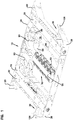
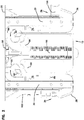
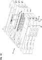
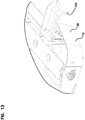
Figure 48 shows a cross-sectional view of a portion of theuniversal mounting mechanism 500, wherein the mountingmechanism 500 is in a locked state or position.Figure 49 illustrates theuniversal mounting mechanism 500 in an unlocked position.Figure 50 illustrates a partially exploded perspective view of a portion of theuniversal mounting mechanism 500 being used with the opticalfiber distribution element 510, which is similar to theelements Figures 30-47 , as noted above.Figure 51 illustrates theuniversal mounting mechanism 500 with the universal mountingbrackets 502 of themechanism 500 mounted to theelement 510.Figure 51A is a close-up view of a portion of theuniversal mounting mechanism 500, illustrating alocking spring 504 of themechanism 500 in a locked position with respect to theuniversal mounting bracket 502 of themechanism 500.Figure 52 is a cross-sectional view of a portion of theuniversal mounting mechanism 500 showing the positional relationship between theuniversal mounting bracket 502 and arelease handle 506 of the mountingmechanism 500 when themechanism 500 is in a locked state. - The
universal mounting mechanism 500 generally includes the right and left universal mountingbrackets 502, release handles 506 for each of the mountingbrackets 502, acover 508 for each of the mountingbrackets 502, and thelocking spring 504 for each of the mountingbrackets 502. - In the depicted embodiment, each of the universal mounting
brackets 502 is designed for mounting twostacked elements 510. Thus, each of the right and left mountingbrackets 502 includes twolatch openings 512 adjacent thefront 514 of the mounting bracket 502 (one for each element 510) and upper and lower mountingtabs 516 at the rear 518 of thebracket 502. - In the given embodiment, the mounting
tabs 516 at the rear 518 of the mountingbrackets 502 are designed to slidably mount thebrackets 502 to fixtures such as telecommunications racks along a sideway or lateral direction. As such, in mountingelements 510 to a rack, the universal mountingbrackets 502 are initially slid into openings provided on the rack using the mountingtabs 516. Once thebrackets 502 are secured on a rack, theelements 510 can be slid onto thebrackets 502 in a sliding fashion, as will be described in further detail. Thelatch openings 512 of thebrackets 502 are then used to lock theelements 510 in place. - In using the
universal mounting mechanism 500 of the present disclosure, eachelement 510, on each of the right and left sides thereof, defines abracket channel 520. Thechannel 520 is configured to slidably receive thefront portions 514 of the mountingbrackets 502. Thecover 508 closes thebracket channel 520 to the exterior of eachelement 510. Thecover 508 defines adeflection ramp 522 at the inner face thereof, the purpose of which will be discussed in further detail below. The lockingspring 504 is mounted to eachelement 510 such that anend portion 524 of thelocking spring 504 can flex in and out of the latch opening 512 of theuniversal mounting bracket 502. As shown in the cross-sectional views ofFigures 48 and49 and inFigures 51 and51A , theend portion 524 of thelocking spring 504 defines aperpendicular locking face 526 and anangular insertion face 528. When anelement 510 is initially being slidably mounted on the mountingbracket 502, the angledinsertion face 528 rides over thefront end 530 of thefront portion 514 of the mountingbracket 502 until theend portion 524 of thelocking spring 504 flexibly snaps into thelatch opening 512. - The
element 510, at this point, is prevented from being pulled out forwardly. The lockingspring 504 abuts an innerfront face 532 defined by the latch opening 512 of the mountingbracket 502 to prevent removal of the chassis from a rack. - The release handle 506 is positioned between the locking
spring 504 and thecover 508. The release handle 506 has agrip portion 534 for pulling the release handle 504 forwardly to release the chassis for removal from the mountingbrackets 502. The release handle 504 also defines adeflection tab 536 at therear end 538. Thedeflection tab 536 is configured to ride over thedeflection ramp 522 of thecover 508 when thegrip portion 534 is pulled forwardly. The interaction of thedeflection tab 536 and thedeflection ramp 522 causes lateral inward movement of thedeflection tab 536, which in turn, pushes thespring 504 laterally inwardly, clearing theend portion 524 of thelocking spring 504 from the latchingopening 512. In this manner, when therelease handle 506 is pulled forwardly, the interaction of thedeflection tab 536 and thedeflection ramp 522 causes the release of thespring 504, and thus theentire element 510, from the mountingbracket 502. The chassis and theentire element 510 can be pulled forwardly from the mountingbracket 502. - In using the
universal mounting mechanism 500 on theelement 510, a tray of theelement 510 has to be pulled from its chassis to allow enough room for gripping the release handle 506 as seen inFigure 52 , to pull it forwardly. In initially mounting theelement 510 to a rack using theuniversal mounting mechanism 500, therelease handle 506 has to be either pushed rearwardly by the user to allow thespring 504 to be positioned in its locking position or the user can simply push a tray of theelement 510 rearwardly to contact thegrip portion 534 of therelease handle 506 to push the release handle 506 rearwardly. Thus, when theelement 510 is mounted to a rack using theuniversal mounting mechanism 500, the release handle 506 must be in its rearward position to allow thespring 504 to be in its locking position. Otherwise, if therelease handle 506 is in its forward position, theelement 510 can simply slide out of thebrackets 502. - The release handle 506 defines a
positive stop 540 that is configured to abut astop face 542 defined by a portion of aslide mechanism 544 within theelement 510. The abutment of thestop 540 with thestop face 542 prevents further forward pulling of therelease handle 506. - The
universal mounting mechanism 500 includes a design that may be retrofitted on a number of telecommunications chassis. As long as abracket channel 520 is provided in the chassis and the chassis includes enough spacing on the sides thereof for receiving alocking spring 504, arelease handle 506, and acover 508 for interacting with therelease handle 506 and closing themounting mechanism 500 to the exterior of the chassis, theuniversal mounting mechanism 500 can be utilized on a given chassis. - Also, as noted above, the
rear portion 518 of the mountingbrackets 502 may be modified to fit different types of mounting configurations on different types of telecommunications racks, frames, or cabinets. The mounting arrangement of thebrackets 502 of the present disclosure that utilizes thetabs 516 for lateral slide-locking is simply one example of a mounting arrangement. Also, even though the mountingmechanism 500 of the present disclosure has been shown with mountingbrackets 502 that can accommodate two vertically stackedelements 510, the mountingbrackets 502 can be modified to receive other number of chassis, including a single chassis perbracket 502. - In the given embodiment, the locking
spring 504 is fixed to the chassis withfasteners 545, allowing theend portion 524 of thelocking spring 504 to be flexible. Other fixing methods may be used for thelocking spring 504 in other types of telecommunications equipment. -
- 10
- element
- 12
- block
- 20
- chassis
- 24
- tray
- 30
- slide mechanism
- 32
- gears
- 34
- rack
- 36
- entry points
- 38
- radius limiters
- 50
- mounting structure
- 52
- adapters
- 56
- T-shaped frame member
- 58
- hinge
- 62
- top frame member
- 64
- bottom frame member
- 70
- adapter blocks
- 72
- connectors
- 74
- cables
- 76
- pathway
- 78
- upper level
- 80
- lower level
- 84
- portion
- 86
- flanges
- 90
- radius limiters
- 96
- openings
- 100
- cable mount
- 102
- cable wrap
- 106
- radius limiters
- 210
- element
- 220
- chassis
- 224
- tray
- 230
- slide mechanism
- 238
- radius limiters
- 256
- frame members
- 258
- hinges
- 260
- middle portion
- 262
- openings
- 264
- side portions
- 266
- cover
- 268
- latches
- 270
- radius limiters
- 276
- pathway
- 278
- upper level
- 280
- lower level
- 284
- radius limiters
- 286
- cable mounts
- 288
- dovetail
- 290
- opening
- 292
- block
- 294
- bar
- 296
- fasteners
- 310
- element
- 330
- slide mechanism
- 332
- wheels
- 334
- wire
- 336
- wire
- 340
- first part
- 342
- second part
- 344
- third part
- 410
- element
- 420
- radius limiter
- 430
- friction members
- 500
- universal mounting mechanism
- 502
- universal mounting bracket
- 504
- locking spring
- 506
- release handle
- 508
- cover
- 510
- element
- 512
- latch openings
- 514
- front portion of the mounting bracket
- 516
- mounting tabs
- 518
- rear portion of the mounting bracket
- 520
- bracket channel
- 522
- deflection ramp
- 524
- end portion of the locking spring
- 526
- perpendicular locking face
- 528
- angular insertion face
- 530
- front end
- 532
- inner front face
- 534
- grip portion
- 536
- deflection tab
- 538
- rear end of the release handle
- 540
- positive stop
- 542
- stop face
- 544
- slide mechanism
- 545
- fasteners
- This application is a divisional application of European patent application number
EP14718620.9 EP2989496A . The original claims of the parent application are repeated below as clauses in the present specification and form part of the content of this divisional application as filed. -
- 1. A mounting mechanism (500) for mounting a telecommunications chassis to a telecommunications fixture, the mounting mechanism (500) comprising:
- a mounting bracket (502) defining a rear portion (518) configured for mounting to the telecommunications fixture and a front portion (514) configured to slidably receive the telecommunications chassis, the front portion (514) including a latch opening (512);
- a locking spring (504) configured to be mounted to the telecommunications chassis, the locking spring (504) defining a portion (524) configured to flex laterally to snap in to the latch opening (512);
- a release handle (506) configured to be slidably mounted to the telecommunications chassis, the release handle (506) defining a deflection tab (536) for moving the locking spring (504) out of the latch opening (512) of the mounting bracket (502) when the release handle (506) is slid along a rearward to forward direction with respect to the telecommunications chassis; and
- a cover (508) configured to be mounted to the telecommunications chassis, the cover (508) defining a deflection ramp (522) configured to interact with the deflection tab (536) of the release handle (506) for moving the deflection tab (536) laterally to contact the locking spring (504) when the release handle (506) is slid with respect to the telecommunications chassis.
- 2. A mounting mechanism (500) according to
clause 1, wherein release handle (506) includes a grip portion (534) adjacent a front end of the release handle (506) for slidably pulling the release handle (506). - 3. A mounting mechanism (500) according to
clause 1, further comprising two of the mounting brackets (502), two of the locking springs (504), two of the release handles (506), and two of the covers (508), one set configured to be mounted to a right side and one set configured to be mounted to a left side of the chassis. - 4. A mounting mechanism (500) according to
clause 1, wherein the telecommunications fixture is a telecommunications rack configured to receive the telecommunications chassis in vertically stacked arrangement. - 5. A mounting mechanism (500) according to
clause 1, wherein the telecommunications chassis includes a slidable tray (224) housing fiber optic equipment. - 6. A mounting mechanism (500) according to
clause 1, wherein the front portion (514) of the mounting bracket (502) is configured to be slidably inserted into a bracket channel (520) defined by the telecommunications chassis. - 7. A telecommunications system wherein the mounting mechanism (500) of
clause 1 is mounted between the telecommunications chassis and the telecommunications fixture. - 8. A telecommunications system according to clause 7, wherein the locking spring (504) is mounted to the telecommunications chassis with fasteners (545).
- 9. A method of mounting a telecommunications chassis to a telecommunications fixture, the method comprising:
- mounting a mounting bracket (502) to the telecommunications fixture, the mounting bracket (502) defining a front portion (514) including a latch opening (512);
- sliding the front portion (514) of the mounting bracket (502) into a bracket channel (520) defined on at least one side of the telecommunications chassis;
- laterally flexing a locking spring (504) to snap-fit at least a portion of the locking spring (504) into the latch opening (512); and
- pulling a release handle (506) on the telecommunications chassis along a rearward to forward direction to deflect the locking spring (504) out of the latch opening (512).
- 10. A method according to clause 9, wherein the release handle (506) defines a deflection tab (536) that interacts with a deflection ramp (522) provided on the telecommunications chassis for laterally moving the locking spring (504) out of the latch opening (512) of the mounting bracket (502) when the release handle (506) is slid along the rearward to forward direction with respect to the telecommunications chassis.
- 11. A method according to
clause 10, wherein the deflection ramp (522) is defined by a cover (508) that is mounted on the telecommunications chassis to define the bracket channel (520). - 12. A method according to clause 9, further comprising re-sliding the front portion (514) of the mounting bracket (502) into the bracket channel (520) of the telecommunications chassis and laterally flexing the locking spring (504) to snap-fit at least a portion of the locking spring (504) into the latch opening (512).
- 13. A method according to clause 9, further comprising mounting two mounting brackets (502) to the telecommunications fixture, each mounting bracket (502) defining a front portion (514) including a latch opening (512) and sliding the front portion (514) of one of the mounting brackets (502) into a bracket channel (520) defined on the right side of the telecommunications chassis and sliding the front portion (514) of the other of the mounting brackets (502) into a bracket channel (520) defined on the left side of the telecommunications chassis.
- 14. A method according to clause 9, wherein the telecommunications fixture is a telecommunications rack configured to receive telecommunications chassis in vertically stacked arrangement.
- 15. A method according to clause 9, wherein the telecommunications chassis includes a slidable tray (224) housing fiber optic equipment.
Claims (14)
- A telecommunications chassis configured to be removably mounted to a telecommunications fixture having a mounting bracket (502) defining an elongate front portion (514) with a latch opening (512), the telecommunications chassis comprising:a locking spring (504) mounted to the telecommunications chassis, the locking spring (504) defining a portion (524) configured to flex laterally to snap in to the latch opening (512) defined by the elongate front portion (514) of the mounting bracket (502) on the telecommunications fixture to lock the telecommunications chassis with respect to the mounting bracket (502);a release handle (506) slidably mounted relative to the telecommunications chassis, the release handle (506) configured for being pulled in a rearward-to-forward direction, the release handle (506) defining a deflection tab (536); anda deflection ramp (522) defined within the telecommunications chassis, the deflection ramp (522) configured to interact with the deflection tab (536) of the release handle (506) for moving the deflection tab (536) laterally to contact the locking spring (504) when the release handle (506) is slid with respect to the telecommunications chassis, wherein the release handle (506) is configured such that pulling of the release handle (506) in a rearward-to-forward direction relative to the telecommunications chassis causes the deflection tab (536) of the release handle (506) to interact with the deflection ramp (522) of the chassis and move the deflection tab (536) laterally, and wherein lateral movement of the deflection tab (536) causes the deflection tab (536) to contact the locking spring (504) and to cause the portion (524) of the locking spring (504) that is within the latch opening (512) to flex laterally out of the latch opening (512) for releasing the telecommunications chassis from the mounting bracket (502).
- A telecommunications chassis according to claim 1, wherein release handle (506) includes a grip portion (534) adjacent a front end of the release handle (506) for slidably pulling the release handle (506).
- A telecommunications chassis according to claim 1, further comprising two of the locking springs (504), two of the release handles (506), and two of the deflection ramps (522), one set configured to be mounted to a right side and one set configured to be mounted to a left side of the chassis.
- A telecommunications chassis according to claim 1, wherein the telecommunications fixture is a telecommunications rack configured to receive the telecommunications chassis in vertically stacked arrangement.
- A telecommunications chassis according to claim 1, further including a slidable tray (224) housing fiber optic equipment.
- A telecommunications chassis according to claim 1, further comprising a bracket channel (520) for receiving the elongate front portion (514) of the mounting bracket (502).
- A telecommunications chassis according to claim 6, wherein the deflection ramp (522) is defined by a cover (508) that is mounted on the telecommunications chassis to define the bracket channel (520).
- A telecommunications chassis according to claim 1, wherein the locking spring (504) is mounted to the telecommunications chassis with fasteners (545).
- A method of using a telecommunications chassis, the method comprising:- mounting a telecommunications chassis to a mounting bracket (502) on a telecommunications fixture by inserting an elongate front portion (514) of the mounting bracket (502) into a bracket channel (520) defined on at least one side of the telecommunications chassis;- laterally flexing a locking spring (504) of the telecommunications chassis to snap-fit at least a portion of the locking spring (504) into a latch opening (512) defined at the front portion (514) of the mounting bracket (502); and- pulling a release handle (506) on the telecommunications chassis along a rearward to forward direction to deflect the locking spring (504) out of the latch opening (512), wherein the release handle (506) defines a deflection tab (536) that interacts with a deflection ramp (522) provided on the telecommunications chassis for laterally moving the locking spring (504) out of the latch opening (512) of the mounting bracket (502) when the release handle (506) is slid along the rearward to forward direction with respect to the telecommunications chassis, wherein the release handle (506) is configured such that pulling of the release handle (506) in a rearward-to-forward direction relative to the telecommunications chassis causes the deflection tab (536) of the release handle (506) to interact with the deflection ramp (522) of the chassis and move the deflection tab (536) laterally, and wherein lateral movement of the deflection tab (536) causes the deflection tab (536) to contact the locking spring (504) and to cause the portion (524) of the locking spring (504) that is within the latch opening (512) to flex laterally out of the latch opening (512) for releasing the telecommunications chassis from the mounting bracket (502).
- A method according to claim 9, wherein the deflection ramp (522) is defined by a cover (508) that is mounted on the telecommunications chassis to define the bracket channel (520).
- A method according to claim 9, further comprising re-coupling the telecommunications chassis to the mounting bracket (502) such that the front portion (514) of the mounting bracket (502) is re-inserted into the bracket channel (520) of the telecommunications chassis and the locking spring (504) is laterally flexed to snap-fit at least a portion of the locking spring (504) into the latch opening (512).
- A method according to claim 9, further comprising mounting the telecommunications chassis such that the front portion (514) of one of two mounting brackets (502) is slid into a bracket channel (520) defined on a right side of the telecommunications chassis and the front portion (514) of the other of the two mounting brackets (502) is slid into a bracket channel (520) defined on a left side of the telecommunications chassis.
- A method according to claim 9, wherein the telecommunications fixture is a telecommunications rack configured to receive telecommunications chassis in vertically stacked arrangement.
- A method according to claim 9, wherein the telecommunications chassis includes a slidable tray (224) housing fiber optic equipment.
Applications Claiming Priority (3)
| Application Number | Priority Date | Filing Date | Title |
|---|---|---|---|
| US201361815549P | 2013-04-24 | 2013-04-24 | |
| EP14718620.9A EP2989496B1 (en) | 2013-04-24 | 2014-04-22 | Universal mounting mechanism for mounting a telecommunications chassis to a telecommunications fixture |
| PCT/EP2014/058136 WO2014173896A1 (en) | 2013-04-24 | 2014-04-22 | Universal mounting mechanism for mounting a telecommunications chassis to a telecommunications fixture |
Related Parent Applications (2)
| Application Number | Title | Priority Date | Filing Date |
|---|---|---|---|
| EP14718620.9A Division EP2989496B1 (en) | 2013-04-24 | 2014-04-22 | Universal mounting mechanism for mounting a telecommunications chassis to a telecommunications fixture |
| EP14718620.9A Division-Into EP2989496B1 (en) | 2013-04-24 | 2014-04-22 | Universal mounting mechanism for mounting a telecommunications chassis to a telecommunications fixture |
Publications (2)
| Publication Number | Publication Date |
|---|---|
| EP3531179A1 true EP3531179A1 (en) | 2019-08-28 |
| EP3531179B1 EP3531179B1 (en) | 2020-12-23 |
Family
ID=50543061
Family Applications (2)
| Application Number | Title | Priority Date | Filing Date |
|---|---|---|---|
| EP19167992.7A Active EP3531179B1 (en) | 2013-04-24 | 2014-04-22 | Optical fiber distribution system |
| EP14718620.9A Active EP2989496B1 (en) | 2013-04-24 | 2014-04-22 | Universal mounting mechanism for mounting a telecommunications chassis to a telecommunications fixture |
Family Applications After (1)
| Application Number | Title | Priority Date | Filing Date |
|---|---|---|---|
| EP14718620.9A Active EP2989496B1 (en) | 2013-04-24 | 2014-04-22 | Universal mounting mechanism for mounting a telecommunications chassis to a telecommunications fixture |
Country Status (15)
| Country | Link |
|---|---|
| US (4) | US10409020B2 (en) |
| EP (2) | EP3531179B1 (en) |
| CN (2) | CN108957656B (en) |
| AP (1) | AP2015008823A0 (en) |
| AU (2) | AU2014257660B2 (en) |
| BR (1) | BR112015027092B1 (en) |
| DK (2) | DK3531179T3 (en) |
| ES (3) | ES2735635T3 (en) |
| HU (2) | HUE046072T2 (en) |
| NZ (1) | NZ713590A (en) |
| PL (1) | PL2989496T3 (en) |
| RU (1) | RU2656120C2 (en) |
| SA (1) | SA515370036B1 (en) |
| WO (1) | WO2014173896A1 (en) |
| ZA (1) | ZA201507948B (en) |
Families Citing this family (25)
| Publication number | Priority date | Publication date | Assignee | Title |
|---|---|---|---|---|
| NZ708968A (en) | 2013-01-29 | 2018-03-23 | CommScope Connectivity Belgium BVBA | Optical fiber distribution system |
| CN105393151B (en) | 2013-04-24 | 2018-09-18 | 泰科电子瑞侃有限公司 | optical fiber distribution system |
| DK3531179T3 (en) * | 2013-04-24 | 2021-03-01 | CommScope Connectivity Belgium BVBA | OPTICAL FIBER DISTRIBUTION SYSTEM |
| WO2014207210A1 (en) | 2013-06-28 | 2014-12-31 | Tyco Electronics Raychem Bvba | Optical fiber distribution system with staggered cable guides |
| WO2015055586A1 (en) * | 2013-10-18 | 2015-04-23 | Tyco Electronics Raychem Bvba | Mounting system for telecommunications distribution elements |
| CA2984824A1 (en) * | 2016-11-08 | 2018-05-08 | Ortronics, Inc. | Splice managers and related methods of use |
| CN107059657A (en) * | 2017-03-22 | 2017-08-18 | 安徽理工大学 | High-altitude hawser deicing mechanism |
| JP2018185508A (en) * | 2017-04-21 | 2018-11-22 | 株式会社フジクラ | Optical wiring unit, optical fiber tray and wiring guide for optical fiber cord |
| US10670822B2 (en) | 2017-06-28 | 2020-06-02 | Afl Telecommunications Llc | High density patch panel with modular cassettes |
| WO2020043909A1 (en) | 2018-08-31 | 2020-03-05 | CommScope Connectivity Belgium BVBA | Frame assemblies for optical fiber distribution elements |
| EP3844546A1 (en) | 2018-08-31 | 2021-07-07 | CommScope Connectivity Belgium BVBA | Frame assemblies for optical fiber distribution elements |
| DK3844972T3 (en) | 2018-08-31 | 2022-10-17 | CommScope Connectivity Belgium BVBA | FRAME ASSEMBLIES FOR OPTICAL FIBER DISTRIBUTION ELEMENTS |
| EP3844973B1 (en) | 2018-08-31 | 2024-11-06 | CommScope Connectivity Belgium BVBA | Frame assemblies for optical fiber distribution elements |
| WO2020043911A1 (en) | 2018-08-31 | 2020-03-05 | CommScope Connectivity Belgium BVBA | Frame assemblies for optical fiber distribution elements |
| EP3871028B1 (en) | 2018-10-23 | 2025-06-18 | CommScope Connectivity Belgium BVBA | Frame assemblies for optical fiber distribution elements |
| US11947177B2 (en) | 2019-01-25 | 2024-04-02 | CommScope Connectivity Belgium BVBA | Frame assemblies for optical fiber distribution elements |
| WO2020185550A1 (en) | 2019-03-08 | 2020-09-17 | Commscope Technologies Llc | Toolless panel mounting system |
| CN112106383B (en) | 2019-04-17 | 2024-03-12 | 欧博互联网网关有限责任公司 | Wiring board with lifting box for removing |
| US12276857B2 (en) | 2019-10-07 | 2025-04-15 | Commscope Technologies Llc | Fiber distribution hub including sealed splice module |
| US12174443B2 (en) | 2020-01-22 | 2024-12-24 | CommScope Connectivity Belgium BVBA | Cable termination units for optical fiber distribution elements |
| EP4094108B1 (en) | 2020-01-24 | 2025-06-18 | CommScope Connectivity Belgium BVBA | Telecommunications distribution elements |
| US12468106B2 (en) | 2020-02-07 | 2025-11-11 | CommScope Connectivity Belgium BVBA | Telecommunications module arrangements |
| RU209710U1 (en) * | 2021-09-24 | 2022-03-18 | Общество с ограниченной ответственностью "СТР-Телеком" | fiber optic distributor |
| US12256511B2 (en) | 2023-06-26 | 2025-03-18 | Crestron Electronics, Inc. | Universal mounting bracket |
| WO2025188800A1 (en) * | 2024-03-04 | 2025-09-12 | Commscope Technologies Llc | Telecommunications panel with sliding modules |
Citations (1)
| Publication number | Priority date | Publication date | Assignee | Title |
|---|---|---|---|---|
| US20100150518A1 (en) * | 2006-10-02 | 2010-06-17 | Emerson Network Power, Energy Systems, North America, Inc. | Optic Fiber Distribution Hub |
Family Cites Families (353)
| Publication number | Priority date | Publication date | Assignee | Title |
|---|---|---|---|---|
| US2864656A (en) | 1954-06-25 | 1958-12-16 | Yorinks Alexander | Slide mechanism |
| NL193890A (en) | 1954-12-27 | |||
| US3901564A (en) | 1973-10-29 | 1975-08-26 | Henry P Armstrong | Drawer extensible slide chassis |
| US4070076A (en) | 1977-05-05 | 1978-01-24 | The Raymond Lee Organization, Inc. | Drawer sliding device |
| DE2735106C2 (en) | 1977-08-04 | 1983-09-01 | AEG-Telefunken Nachrichtentechnik GmbH, 7150 Backnang | Cable set for a telecommunication cable |
| US4172625A (en) | 1977-12-15 | 1979-10-30 | Comerco, Inc. | Drawer extenders |
| DE2918572A1 (en) | 1978-06-13 | 1980-01-03 | Blum Gmbh Julius | EXTENSION GUIDE SET FOR DRAWERS |
| DE2918309C2 (en) | 1979-05-07 | 1982-11-04 | Heino Schulz Kunststoffverarbeitung, 5300 Bonn | Drawer pull-out device |
| US4373776A (en) | 1980-06-30 | 1983-02-15 | Northern Telecom Limited | Protection case for optical fiber splices |
| US4359262A (en) | 1980-06-30 | 1982-11-16 | Northern Telecom Limited | Tray for organizing optical fiber splices and enclosures embodying such trays |
| JPS58109707U (en) | 1982-01-19 | 1983-07-26 | 日本電気株式会社 | Terminal board storage device |
| FR2531576A1 (en) | 1982-08-04 | 1984-02-10 | Cit Alcatel | CONNECTION AND OPTO-ELECTRONIC INTERFACE |
| FR2531544B1 (en) | 1982-08-04 | 1985-01-25 | Cit Alcatel | OPTICAL CABLE HEAD |
| JPS5974523A (en) | 1982-10-21 | 1984-04-27 | Furukawa Electric Co Ltd:The | Optical fiber connection box |
| FR2538918A1 (en) | 1983-01-05 | 1984-07-06 | Telecommunications Sa | FIBER OPTIC CONNECTION AND BREWING BOX |
| DE3308682C2 (en) | 1983-03-11 | 1985-12-05 | Krone Gmbh, 1000 Berlin | Matrix main distributor |
| US4494806A (en) | 1983-05-13 | 1985-01-22 | Leslie Metal Arts Company | Spring loaded drawer assembly with mechanical damping |
| US4595255A (en) | 1983-08-24 | 1986-06-17 | Fiberlan, Inc. | Optical fiber wiring center |
| FR2556895B1 (en) | 1983-12-20 | 1986-12-19 | Lignes Telegraph Telephon | DEVICE FOR CONNECTING CABLES, PARTICULARLY WITH OPTICAL FIBERS |
| DE3347621A1 (en) | 1983-12-30 | 1985-07-11 | Wilhelm Sedlbauer GmbH Fabrik für Feinmechanik und Elektronik, 8000 München | DISTRIBUTION RACK FOR FIBERGLASS CABLE ENDS |
| JPS60169811A (en) | 1984-02-14 | 1985-09-03 | Furukawa Electric Co Ltd:The | Containing device for connection excessive length of optical fiber |
| GB2138057B (en) | 1984-04-11 | 1987-09-30 | Tekken Constr Co | Method of building strengthened, embanked foundation |
| US4630886A (en) | 1984-04-16 | 1986-12-23 | At&T Bell Laboratories | Lightguide distributing unit |
| JPS6155607A (en) | 1984-08-28 | 1986-03-20 | Fujitsu Ltd | Light distributing board |
| JPS6190104A (en) | 1984-10-09 | 1986-05-08 | Nec Corp | Optical adapter installation structure |
| CA1249741A (en) | 1984-10-25 | 1989-02-07 | Michael J. Donaldson | Optical cable terminating equipment |
| FR2575020B1 (en) | 1984-12-14 | 1987-02-13 | Nozick Jacques | DISTRIBUTOR FOR OPTICAL CABLES |
| US4699455A (en) | 1985-02-19 | 1987-10-13 | Allen-Bradley Company | Fiber optic connector |
| DE3511653A1 (en) | 1985-03-29 | 1986-10-02 | Siemens AG, 1000 Berlin und 8000 München | BASE WITH INSERT FOR A COUPLING PANEL BETWEEN FIBERGLASS CABLES |
| US4765710A (en) | 1985-07-30 | 1988-08-23 | Siemens Aktiengesellschaft | Distributing frame for optical waveguides and the like |
| FR2587127B1 (en) | 1985-09-06 | 1987-10-23 | Valleix Paul | STRUCTURE FOR OPTICAL CONNECTIONS |
| US4792203A (en) | 1985-09-17 | 1988-12-20 | Adc Telecommunications, Inc. | Optical fiber distribution apparatus |
| US4737039A (en) | 1986-12-08 | 1988-04-12 | Knape & Vogt Manufacturing Company | Drawer rail carrier roller mount |
| US4840449A (en) | 1988-01-27 | 1989-06-20 | American Telephone And Telegraph Company, At&T Bell Laboratories | Optical fiber splice organizer |
| US4820007A (en) | 1988-02-12 | 1989-04-11 | American Telephone And Telegraph Company At&T Bell Laboratories | Cable closure and methods of assembling |
| US4898448A (en) | 1988-05-02 | 1990-02-06 | Gte Products Corporation | Fiber distribution panel |
| US4900123A (en) | 1988-08-29 | 1990-02-13 | Gte Products Corporation | 1550 nm fiber distribution panel |
| DE3836273C2 (en) | 1988-10-25 | 1997-05-07 | Standard Praezision Gmbh | Synchronized three-part telescopic rail for tension members |
| DE3838428A1 (en) | 1988-11-12 | 1990-05-31 | Philips Patentverwaltung | SWITCH DISTRIBUTOR FOR THE PRODUCTION OF FREELY SELECTABLE OPTICAL CONNECTORS |
| US5071211A (en) | 1988-12-20 | 1991-12-10 | Northern Telecom Limited | Connector holders and distribution frame and connector holder assemblies for optical cable |
| US5013121A (en) | 1989-06-29 | 1991-05-07 | Anton Mark A | Optical fiber storage container |
| US5067678A (en) | 1989-07-31 | 1991-11-26 | Adc Telecommunications, Inc. | Optic cable management system |
| US5316243A (en) | 1989-07-31 | 1994-05-31 | Adc Telecommunications, Inc. | Optic cable management |
| US4995688A (en) | 1989-07-31 | 1991-02-26 | Adc Telecommunications, Inc. | Optical fiber distribution frame |
| US4986762A (en) | 1989-08-15 | 1991-01-22 | Minnesota Mining And Manufacturing Company | Termination module for use in an array of modules |
| US4971421A (en) | 1989-09-29 | 1990-11-20 | Reliance Comm/Tec Corporation | Fiber optic splice and patch enclosure |
| US5142606A (en) | 1990-01-22 | 1992-08-25 | Porta Systems Corp. | Optical fiber cable distribution frame and support |
| US5100221A (en) | 1990-01-22 | 1992-03-31 | Porta Systems Corp. | Optical fiber cable distribution frame and support |
| US4991928A (en) | 1990-02-20 | 1991-02-12 | Siecor Corporation | Movable clamp for fiber optic enclosures |
| US5142607A (en) | 1990-03-20 | 1992-08-25 | Rittal-Werk Rudolf Loh Gmbh & Co. Kg | Splice box for optical wave guide |
| US5174675A (en) | 1990-05-07 | 1992-12-29 | Inventio Ag | Guide bar for an elevator door |
| FR2663917B1 (en) | 1990-06-29 | 1993-06-04 | Cit Alcatel | MODULAR DEVICE FOR STORING RESERVES OF TRANSMISSION SUPPORT ON LINKS, PARTICULARLY FIBER OPTIC. |
| US5066149A (en) | 1990-09-11 | 1991-11-19 | Adc Telecommunications, Inc. | Splice tray with slack take-up |
| ES2100189T3 (en) | 1990-10-04 | 1997-06-16 | Alcatel Cable Interface | OPTICAL CONNECTION BOX. |
| US5138688A (en) | 1990-11-09 | 1992-08-11 | Northern Telecom Limited | Optical connector holder assembly |
| US5127082A (en) | 1991-03-22 | 1992-06-30 | The Siemon Company | Fiber optic patch panel |
| US5129030A (en) | 1991-05-30 | 1992-07-07 | At&T Bell Laboratories | Movable lightguide connector panel |
| FR2678076B1 (en) | 1991-06-20 | 1994-09-23 | Cit Alcatel | MODULE FOR STORING A TRANSMISSION SUPPORT RESERVE ON A LINK, PARTICULARLY WITH OPTICAL FIBER AND STORAGE DEVICE COMPRISING A SET OF SUCH MODULES. |
| US5167001A (en) | 1991-09-03 | 1992-11-24 | Northern Telecom Limited | Optical fiber storage and connector tray and shelf and tray assembly |
| DE4133375C1 (en) | 1991-10-05 | 1993-04-22 | Krone Ag | |
| FR2682488B1 (en) | 1991-10-15 | 1994-01-21 | Bruno Capelle | MODULAR CABLES HEAD WITH LARGE CAPACITY FIBER OPTICS. |
| ES1019586Y (en) | 1991-12-12 | 1992-11-01 | Telefonica De Espana, S.A. | TERMINAL JOINT AND MODULAR OPTICAL DISTRIBUTION. |
| US5247603A (en) | 1992-01-24 | 1993-09-21 | Minnesota Mining And Manufacturing Company | Fiber optic connection system with exchangeable cross-connect and interconnect cards |
| FR2687800B1 (en) | 1992-02-21 | 1994-04-08 | Mars Actel | ADAPTABLE CASSETTE FOR LOVING AND SPLICING OPTICAL FIBERS. |
| FR2687744B1 (en) | 1992-02-21 | 1994-04-08 | Mars Actel | SET OF ARTICULATED FLAT MODULES. |
| US5202942A (en) | 1992-04-03 | 1993-04-13 | Amp Incorporated | Cable termination member for fiber optic connectors having improved strain relief |
| US5275064A (en) | 1992-06-12 | 1994-01-04 | General Devices Co., Inc. | Extensible platform with cable drive system |
| US5240209A (en) | 1992-11-17 | 1993-08-31 | Telect, Inc. | Telecommunication multiple cable carrier |
| US5323480A (en) | 1992-11-25 | 1994-06-21 | Raychem Corporation | Fiber optic splice closure |
| US5335349A (en) | 1992-12-14 | 1994-08-02 | Telect, Inc. | Telecommunication overhead cable distribution assembly |
| FR2703160B1 (en) | 1993-03-26 | 1995-06-02 | Corning Inc | Cassette for optical fiber device, fitted with a bundle of flexible fiber protection tubes. |
| US5363467A (en) | 1993-05-28 | 1994-11-08 | Minnesota Mining And Manufacturing Company | Compact fiber optic housing |
| US5339379A (en) | 1993-06-18 | 1994-08-16 | Telect, Inc. | Telecommunication fiber optic cable distribution apparatus |
| US5412751A (en) | 1993-08-31 | 1995-05-02 | The Siemon Company | Retrofittable multimedia patch management system |
| GB9318632D0 (en) | 1993-09-08 | 1993-10-27 | Raychem Sa Nv | Optical fibre organizer |
| GB9318633D0 (en) | 1993-09-08 | 1993-10-27 | Raychem Sa Nv | Organization of optical fibres |
| US5353367A (en) | 1993-11-29 | 1994-10-04 | Northern Telecom Limited | Distribution frame and optical connector holder combination |
| US5490229A (en) | 1993-12-08 | 1996-02-06 | At&T Ipm Corp. | Slidably mounted optical fiber distribution tray |
| TW232757B (en) | 1994-01-21 | 1994-10-21 | Adc Telecommunications Inc | High-density fiber distribution frame |
| US5402515A (en) | 1994-03-01 | 1995-03-28 | Minnesota Mining And Manufacturing Company | Fiber distribution frame system, cabinets, trays and fiber optic connector couplings |
| DE4413136C1 (en) | 1994-04-19 | 1995-05-04 | Loh Kg Rittal Werk | Optical-fibre splice box |
| US5511144A (en) | 1994-06-13 | 1996-04-23 | Siecor Corporation | Optical distribution frame |
| GB2292466B (en) | 1994-08-15 | 1997-09-10 | Pirelli General Plc | Guiding optical fibres in ducts |
| US5530783A (en) | 1994-08-31 | 1996-06-25 | Berg Technology, Inc. | Backplane optical fiber connector for engaging boards of different thicknesses and method of use |
| WO1996010203A1 (en) | 1994-09-28 | 1996-04-04 | Telephone Cables Limited | A splice tray |
| US5509096A (en) | 1994-10-28 | 1996-04-16 | Syntec Inc. | Receptacle and plug fiber optic connector assembly |
| DE4442823A1 (en) | 1994-12-01 | 1996-06-05 | Siemens Ag | Cassette module for optical fibers |
| DE29504191U1 (en) | 1995-03-01 | 1996-03-28 | Krone Ag, 14167 Berlin | Insert for receiving devices of the LWL technology |
| US5613030A (en) | 1995-05-15 | 1997-03-18 | The Whitaker Corporation | High density fiber optic interconnection enclosure |
| US5724469A (en) | 1996-01-26 | 1998-03-03 | Ortronics, Inc. | Adjustable fiber storage plate |
| US5811055A (en) | 1996-02-06 | 1998-09-22 | Geiger; Michael B. | Torch mounted gas scavaging system for manual and robotic welding and cutting torches |
| US5836148A (en) | 1996-02-06 | 1998-11-17 | Kunimorikagaku Ltd. | Cable chain |
| DE69607132T2 (en) | 1996-02-17 | 2000-08-31 | Horizon International, Inc. | Device for feeding paper for a book binding machine |
| DE19611770C2 (en) | 1996-03-14 | 1998-04-09 | Krone Ag | Manageable splice cassette |
| US5715348A (en) | 1996-03-27 | 1998-02-03 | Next Level Communications | Fiber management system and method for routing optical fiber having a minimum bend radius |
| DE69713544T2 (en) | 1996-04-12 | 2003-02-20 | Telephone Cables Ltd., Dagenham | Arrangement of an optical fiber |
| DE59710502D1 (en) | 1996-10-07 | 2003-09-04 | Blum Gmbh Julius | Pull-out guide set for drawers |
| WO1998041891A1 (en) | 1997-03-17 | 1998-09-24 | Tii Industries, Inc. | Fiber optic cable bend radius controller |
| US5802237A (en) | 1997-04-18 | 1998-09-01 | Minnesota Mining And Manufacturing Company | Optical fiber organizer |
| US6022150A (en) | 1997-04-30 | 2000-02-08 | The Whitaker Corporation | Fiber optic connector |
| US6128946A (en) | 1997-06-26 | 2000-10-10 | Crane Nuclear, Inc. | Method and apparatus for on-line detection of leaky emergency shut down or other valves |
| US5975769A (en) | 1997-07-08 | 1999-11-02 | Telect, Inc. | Universal fiber optic module system |
| US5971626A (en) | 1997-08-29 | 1999-10-26 | Siecor Corporation | Fiber optic connector and connector sleeve assembly |
| US6009224A (en) | 1997-11-06 | 1999-12-28 | Allen; Barry Wayne | Fiber optic organizer with lockable trays and method of accessing a tray |
| US5923753A (en) | 1997-11-17 | 1999-07-13 | Adc Telecommunications, Inc. | Optic cable exit trough with bypass |
| US5946440A (en) | 1997-11-17 | 1999-08-31 | Adc Telecommunications, Inc. | Optical fiber cable management device |
| US6027252A (en) | 1997-12-19 | 2000-02-22 | The Whitaker Corporation | Simplified fiber optic receptacle |
| US5966492A (en) | 1997-12-19 | 1999-10-12 | Antec Corporation | Apparatus for storing and splicing optical fibers |
| GB9801198D0 (en) | 1998-01-21 | 1998-03-18 | Raychem Sa Nv | Optical fibre assembly |
| US5978540A (en) | 1998-04-23 | 1999-11-02 | Antec Corporation | Apparatus for interconnecting optical fibers |
| US6208796B1 (en) | 1998-07-21 | 2001-03-27 | Adc Telecommunications, Inc. | Fiber optic module |
| US6085003A (en) | 1998-07-28 | 2000-07-04 | Us Conec Ltd | Multifiber connector having a free floating ferrule |
| FR2782171B1 (en) | 1998-08-04 | 2001-11-30 | Pouyet Sa | FIBER OPTIC CABLES CONNECTION DEVICE |
| US6263141B1 (en) | 1998-09-09 | 2001-07-17 | Adc Telecommunications, Inc. | Optical fiber cable management device including storage tray |
| US6076908A (en) | 1998-09-17 | 2000-06-20 | Platt And Labonia Co. | Drawer for storage cabinet |
| US6215938B1 (en) | 1998-09-21 | 2001-04-10 | Adc Telecommunications, Inc. | Fiber optic cabinet and tray |
| US6496638B1 (en) | 1998-10-23 | 2002-12-17 | Lucent Technologies Inc. | Optical fiber cassette |
| US6468112B1 (en) | 1999-01-11 | 2002-10-22 | Adc Telecommunications, Inc. | Vertical cable management system with ribcage structure |
| US6760531B1 (en) | 1999-03-01 | 2004-07-06 | Adc Telecommunications, Inc. | Optical fiber distribution frame with outside plant enclosure |
| JP2000286574A (en) | 1999-03-31 | 2000-10-13 | Nec Eng Ltd | Cable-clamping unit |
| US6236795B1 (en) | 1999-06-07 | 2001-05-22 | E. Walter Rodgers | High-density fiber optic cable distribution frame |
| GB9913264D0 (en) | 1999-06-09 | 1999-08-04 | Raychem Sa Nv | Detent for optical fibres |
| US6256444B1 (en) | 1999-09-21 | 2001-07-03 | Antec Corporation | Adjustable guide for organizing optical fibers in an equipment rack |
| GB9926487D0 (en) | 1999-11-10 | 2000-01-12 | Raychem Sa Nv | Optical fibre management |
| US6226436B1 (en) | 1999-11-18 | 2001-05-01 | Lucent Technologies, Inc. | Fiber optical pedestal |
| DE19956067A1 (en) | 1999-11-22 | 2001-05-23 | Rxs Kabelgarnituren Gmbh & Co | Cassette for accommodating optical fibres, surplus lengths, splices, etc., has differently shaped splice holders for various types of splice protection elements, and add-on elements for adapting to required use |
| US6504988B1 (en) | 2000-01-24 | 2003-01-07 | Adc Telecommunications, Inc. | Cable management panel with sliding drawer |
| US6438310B1 (en) | 2000-01-24 | 2002-08-20 | Adc Telecommunications, Inc. | Cable management panel with sliding drawer |
| US6301424B1 (en) | 2000-04-13 | 2001-10-09 | Lucent Technologies Inc. | Distribution frame cable routing apparatus |
| US6439523B1 (en) | 2000-06-02 | 2002-08-27 | Panduit Corp. | Universal mounting system for a fiber optic management center |
| US20030020379A1 (en) | 2000-07-13 | 2003-01-30 | Larsen Lars R. | Cabinet with a removable and reversible door |
| US6612515B1 (en) | 2000-08-28 | 2003-09-02 | Adc Telecommunications, Inc. | Telecommunications cable storage spool |
| US6360050B1 (en) | 2000-09-08 | 2002-03-19 | Telect, Inc. | High density fiber distribution tray system |
| US6381393B1 (en) | 2000-11-08 | 2002-04-30 | Adc Telecommunications, Inc. | Fanning strip for cable management panel |
| US6845207B2 (en) | 2001-02-12 | 2005-01-18 | Fiber Optic Network Solutions Corp. | Optical fiber enclosure system |
| US6625374B2 (en) | 2001-03-07 | 2003-09-23 | Adc Telecommunications, Inc. | Cable storage spool |
| US6600866B2 (en) | 2001-03-13 | 2003-07-29 | 3M Innovative Properties Company | Filament organizer |
| US6539161B2 (en) | 2001-03-16 | 2003-03-25 | Adc Telecommunications, Inc. | Cable routing clip |
| US7266280B2 (en) | 2001-03-16 | 2007-09-04 | Avago Technologies Fiber Ip (Singapore) Pte. Ltd. | Cable storage device providing continuous adjustability with controlled bend radius |
| GB0108255D0 (en) | 2001-04-02 | 2001-05-23 | Tyco Electronics Raychem Nv | Optical fibre organiser |
| US6674952B2 (en) | 2001-04-30 | 2004-01-06 | Telect, Inc. | Fiber optic cable bend radius protection system |
| US6792190B2 (en) | 2001-06-01 | 2004-09-14 | Telect, Inc. | High density fiber optic splitter/connector tray system |
| US7079744B2 (en) | 2001-07-06 | 2006-07-18 | Adc Telecommunications, Inc. | Cable management panel with sliding drawer and methods |
| US6819857B2 (en) | 2001-10-12 | 2004-11-16 | Adc Telecommunications, Inc. | Rotating vertical fiber tray and methods |
| US6594434B1 (en) | 2001-10-26 | 2003-07-15 | Ciena Corporation | Fiber optic cables management and measurement apparatus |
| KR100404923B1 (en) | 2001-11-07 | 2003-11-07 | 김우경 | Method for making a korean herb tea with effect for recovering fatigue |
| FR2832226B1 (en) | 2001-11-13 | 2004-10-22 | Nexans | OPTICAL FIBER DISTRIBUTION AND CONNECTION MODULE FOR AN OPTICAL DISTRIBUTOR |
| FR2832225B1 (en) | 2001-11-13 | 2004-08-27 | Nexans | HIGH DENSITY OPTICAL DISTRIBUTOR AND METHOD FOR THE GARAGE OF SUCH A DISTRIBUTOR |
| US6591051B2 (en) | 2001-11-16 | 2003-07-08 | Adc Telecommunications, Inc. | Fiber termination block with angled slide |
| DE20200065U1 (en) | 2002-01-03 | 2003-03-06 | CCS Technology, Inc., Wilmington, Del. | Splice cassette |
| FR2836560B1 (en) | 2002-02-25 | 2004-06-18 | Nexans | LOVING CASSETTE FOR OPTICAL FIBERS |
| FR2836561B1 (en) | 2002-02-28 | 2004-06-18 | Nexans | CASSETTE FOR LOVING AND HOLDING SPLICES BETWEEN CONDUCTORS AND ORGANIZER OF A PLURALITY OF SAID CASSETTES |
| US6909833B2 (en) | 2002-03-15 | 2005-06-21 | Fiber Optic Network Solutions, Inc. | Optical fiber enclosure system using integrated optical connector and coupler assembly |
| US6850685B2 (en) | 2002-03-27 | 2005-02-01 | Adc Telecommunications, Inc. | Termination panel with pivoting bulkhead and cable management |
| US7116777B2 (en) | 2002-04-05 | 2006-10-03 | Adc Telecommunications, Inc. | Termination frame with modules and method |
| EP1495354A2 (en) | 2002-04-12 | 2005-01-12 | Tyco Electronics Raychem NV | Optical circuit enclosure |
| US6937807B2 (en) | 2002-04-24 | 2005-08-30 | Adc Telecommunications, Inc. | Cable management panel with sliding drawer |
| MY131063A (en) | 2002-05-17 | 2007-07-31 | Harn Marketing Sdn Bhd | Guide rails pull-out drawer/equipment |
| US6711339B2 (en) | 2002-05-31 | 2004-03-23 | Adc Telecommunications, Inc. | Fiber management module with cable storage |
| US6957920B2 (en) | 2002-06-24 | 2005-10-25 | Corning Cable Systems Llc | Ferrule assembly having highly protruding optical fibers and an associated fabrication method |
| US6748155B2 (en) | 2002-07-22 | 2004-06-08 | Adc Telecommunications, Inc. | Fiber management drawer and sliding cable slack limiter |
| US6715619B2 (en) | 2002-07-22 | 2004-04-06 | Adc Telecommunications, Inc. | Fiber management drawer and patch panel |
| US6677520B1 (en) | 2002-07-22 | 2004-01-13 | Adc Telecommunications, Inc. | Fanning tray |
| US6796437B2 (en) | 2002-09-16 | 2004-09-28 | Adc Telecommunications, Inc. | Cable trough |
| US6981750B2 (en) | 2002-09-16 | 2006-01-03 | Adc Telecommunications, Inc. | Retainer for hinged door |
| MXPA05003507A (en) | 2002-10-11 | 2005-07-28 | 3M Innovative Properties Co | Drawer for the management of optical fibers. |
| US7086539B2 (en) | 2002-10-21 | 2006-08-08 | Adc Telecommunications, Inc. | High density panel with rotating tray |
| US6804447B2 (en) | 2002-11-05 | 2004-10-12 | Adc Telecommunications, Inc. | Fiber panel with integrated couplers |
| DE10255561A1 (en) | 2002-11-22 | 2004-06-09 | Krone Gmbh | Method and device for coupling optical fibers |
| US6768860B2 (en) | 2002-12-05 | 2004-07-27 | Jds Uniphase Inc. | High density fiber optic module |
| US6865331B2 (en) | 2003-01-15 | 2005-03-08 | Adc Telecommunications, Inc. | Rotating radius limiter for cable management panel and methods |
| US6809258B1 (en) | 2003-02-24 | 2004-10-26 | Cisco Technology, Inc. | Apparatus for cable routing management |
| US6853795B2 (en) | 2003-03-05 | 2005-02-08 | Corning Cable Systems Llc | High density fiber optic distribution frame |
| US7364244B2 (en) * | 2003-05-14 | 2008-04-29 | Hewlett-Packard Development Company | User-controllable latching carrier rail system |
| JP4321111B2 (en) | 2003-05-16 | 2009-08-26 | 日本電気株式会社 | OPTICAL MODULE, METHOD FOR RELEASE LOCK STATUS OF OPTICAL MODULE AND CAGE |
| US6870734B2 (en) | 2003-05-30 | 2005-03-22 | Adc Telecommunications, Inc. | Fiber containment system |
| US20050017614A1 (en) * | 2003-06-23 | 2005-01-27 | Paul Cirocco | Split lock arm for three-piece slide assembly |
| US7171099B2 (en) | 2003-07-31 | 2007-01-30 | Adc Telecommunications, Inc. | Slide arrangement for cable drawer |
| KR200337929Y1 (en) | 2003-10-23 | 2004-01-13 | 허필규 | A Housing for purchase of optical fiber adapter |
| US6920274B2 (en) | 2003-12-23 | 2005-07-19 | Adc Telecommunications, Inc. | High density optical fiber distribution frame with modules |
| US6944383B1 (en) | 2004-04-12 | 2005-09-13 | Adc Telecommunications, Inc. | Cable management panel with sliding drawer and methods |
| US7527436B2 (en) | 2004-07-19 | 2009-05-05 | Molex Incorporated | Ferrule with tilt correction |
| US7317619B2 (en) * | 2004-08-02 | 2008-01-08 | International Business Machines Corporation | Apparatus for inserting and ejecting an electronic enclosure within a cabinet |
| RU45207U1 (en) | 2004-10-14 | 2005-04-27 | Открытое Акционерное Общество "ВЭЛАН" | CABLE INPUTS (OPTIONS) |
| JP4329669B2 (en) * | 2004-10-21 | 2009-09-09 | ソニー株式会社 | Electronics |
| US7171100B2 (en) | 2004-11-03 | 2007-01-30 | Adc Telecommunications, Inc. | Optical fiber slack storage tray for distribution cabinet |
| US7470139B2 (en) * | 2004-11-26 | 2008-12-30 | Fujitsu Component Limited | Transceiver module |
| US7362942B2 (en) | 2005-03-02 | 2008-04-22 | Adc Telecommunications, Inc. | System and method of grounding fiber storage trays |
| US7376323B2 (en) | 2005-05-25 | 2008-05-20 | Adc Telecommunications, Inc. | Fiber optic adapter module |
| US7460758B2 (en) | 2005-06-03 | 2008-12-02 | Telect Inc. | Fiber management system |
| US20070003204A1 (en) | 2005-06-30 | 2007-01-04 | Elli Makrides-Saravanos | Methods and apparatus for splitter modules and splitter module housings |
| US7406240B2 (en) | 2005-07-21 | 2008-07-29 | Ortronics, Inc. | Patch panel for fiber optic network |
| US7416349B2 (en) | 2005-07-27 | 2008-08-26 | Adc Telecommunications, Inc. | Fiber optic adapter module |
| US7397996B2 (en) | 2005-08-02 | 2008-07-08 | Adc Telecommunications, Inc. | Cable management panel with rear entry |
| CN2821666Y (en) * | 2005-08-02 | 2006-09-27 | 鸿富锦精密工业(深圳)有限公司 | Extension locking device |
| JP4875338B2 (en) | 2005-09-13 | 2012-02-15 | ソニー株式会社 | Information processing apparatus and method, and program |
| US7302153B2 (en) | 2005-10-26 | 2007-11-27 | Telect Inc. | Fiber management access system |
| US7292456B2 (en) * | 2005-11-15 | 2007-11-06 | Cisco Technology, Inc. | Techniques for controlling removal of a circuit board from a chassis using a button |
| US7274852B1 (en) | 2005-12-02 | 2007-09-25 | Adc Telecommunications, Inc. | Splice tray arrangement |
| US7720343B2 (en) | 2006-02-13 | 2010-05-18 | Adc Telecommunications, Inc. | Fiber distribution hub with swing frame and modular termination panels |
| US7382961B2 (en) | 2006-05-23 | 2008-06-03 | Telect Inc. | Fiber transitioning |
| US7357667B2 (en) * | 2006-06-22 | 2008-04-15 | Adc Telecommunications, Inc. | Telecommunications patch |
| US7454113B2 (en) | 2006-07-20 | 2008-11-18 | Adc Telecommunications, Inc. | Grounding device for fiber storage trays |
| JP4779875B2 (en) | 2006-08-24 | 2011-09-28 | ソニー株式会社 | Digital-analog converter and video display device |
| US7409137B2 (en) | 2006-10-04 | 2008-08-05 | Adc Telecommunications, Inc. | Slide arrangement for cable drawer |
| US7418182B2 (en) | 2006-10-10 | 2008-08-26 | Adc Telecommunications, Inc. | Cable management drawer with access panel |
| US7437049B2 (en) | 2006-10-10 | 2008-10-14 | Adc Telecommunications, Inc. | Cable management drawer with access panel |
| US7689089B2 (en) | 2006-10-11 | 2010-03-30 | Panduit Corp. | Release latch for pre-terminated cassette |
| US20100092147A1 (en) | 2006-10-16 | 2010-04-15 | Christophe Desard | Optical fiber cable retention device |
| US7583885B2 (en) | 2006-11-28 | 2009-09-01 | Adc Telecommunications, Inc. | Fiber distribution enclosure |
| US7496268B2 (en) | 2006-12-13 | 2009-02-24 | Corning Cable Systems Llc | High density fiber optic hardware |
| US7603018B2 (en) | 2007-01-16 | 2009-10-13 | Tyco Electronics Corporation | Cable enclosure assemblies and methods for using the same |
| US7493002B2 (en) | 2007-01-19 | 2009-02-17 | Adc Telecommunications, Inc. | Fiber optic adapter cassette and panel |
| US7570860B2 (en) | 2007-01-19 | 2009-08-04 | Adc Telecommunications, Inc. | Adapter panel with lateral sliding adapter arrays |
| US7570861B2 (en) | 2007-01-19 | 2009-08-04 | Adc Telecommunications, Inc. | Adapter panel with lateral sliding adapter arrays |
| US7499622B2 (en) | 2007-02-28 | 2009-03-03 | Corning Cable Systems Llc | Fiber optic drop terminals for multiple dwelling units |
| CN201054403Y (en) | 2007-03-02 | 2008-04-30 | 富士康(昆山)电脑接插件有限公司 | Cable connector |
| US7693387B2 (en) | 2007-04-05 | 2010-04-06 | C.E. Communication Systems, Inc. | Cable management system |
| US20080298026A1 (en) | 2007-05-31 | 2008-12-04 | Micro-Star Int'l Co., Ltd. | Holder for electronic device |
| US7567744B2 (en) | 2007-06-06 | 2009-07-28 | Adc Telecommunications, Inc. | Rear drawer latch |
| NZ556111A (en) | 2007-06-22 | 2010-02-26 | Modempak Ltd | Cable management device |
| US7787260B2 (en) | 2007-07-09 | 2010-08-31 | Adc Telecommunications, Inc. | Cable management arrangement for a telecommunications cabinet |
| US8798427B2 (en) | 2007-09-05 | 2014-08-05 | Corning Cable Systems Llc | Fiber optic terminal assembly |
| EP2195897B1 (en) | 2007-09-06 | 2017-02-22 | Hoffman Enclosures, Inc. | Vertical cable manager |
| US8861918B2 (en) | 2007-09-07 | 2014-10-14 | Corning Cable Systems Llc | Fiber optic adapter module and tray |
| US7945138B2 (en) | 2007-10-01 | 2011-05-17 | Clearfield, Inc. | Modular optical fiber cassette |
| US8059932B2 (en) | 2007-10-01 | 2011-11-15 | Clearfield, Inc. | Modular optical fiber cassette |
| US7751674B2 (en) | 2007-10-01 | 2010-07-06 | Clearfield, Inc. | Modular optical fiber cassettes and fiber management methods |
| US8179684B2 (en) * | 2007-10-29 | 2012-05-15 | Adc Telecommunications, Inc. | Sliding adapter panel with living hinge and forward/rearward locking |
| US7747125B1 (en) | 2007-11-07 | 2010-06-29 | Alliance Fiber Optic Products, Inc. | Structured fiber optic cassette with multi-furcated cable access |
| US7744286B2 (en) | 2007-12-11 | 2010-06-29 | Adc Telecommunications, Inc. | Hardened fiber optic connection system with multiple configurations |
| AU2009204505A1 (en) | 2008-01-07 | 2009-07-16 | Chatsworth Products, Inc. | Apparatus and method for organizing cables in a cabinet |
| US20090196563A1 (en) | 2008-02-01 | 2009-08-06 | Mullsteff David M | Multi-Fiber Optical Patch Cord Breakout Assembly |
| US7606458B2 (en) | 2008-02-21 | 2009-10-20 | Tyco Telecommunications (Us) Inc. | Movable optical fiber connection system and optical fiber bend limiting device for use therein |
| US7889961B2 (en) | 2008-03-27 | 2011-02-15 | Corning Cable Systems Llc | Compact, high-density adapter module, housing assembly and frame assembly for optical fiber telecommunications |
| US7978951B2 (en) | 2008-03-28 | 2011-07-12 | Adc Telecommunications, Inc. | Bulkhead with angled openings and method |
| US7764859B2 (en) | 2008-03-28 | 2010-07-27 | Adc Telecommunications, Inc. | Universal cable management panel |
| US7715681B2 (en) | 2008-03-28 | 2010-05-11 | Adc Telecommunications, Inc. | Rear latch arrangement for sliding drawer |
| US8315498B2 (en) | 2008-04-11 | 2012-11-20 | Adc Telecommunications, Inc. | Fiber management panel |
| US8041175B2 (en) | 2008-05-05 | 2011-10-18 | Adc Telecommunications, Inc. | Front-access locking arrangement for sliding drawer |
| US7876993B2 (en) | 2008-05-05 | 2011-01-25 | Adc Telecommunications, Inc. | Drawer arrangement with rack and pinion |
| CN101583256A (en) * | 2008-05-12 | 2009-11-18 | 爱德龙通讯系统(上海)有限公司 | Cable management panel |
| US8290333B2 (en) | 2008-08-29 | 2012-10-16 | Corning Cable Systems Llc | Fiber optic cable assemblies with furcation bodies having features for manufacturing and methods of making the same |
| US8285104B2 (en) | 2008-08-29 | 2012-10-09 | Corning Cable Systems Llc | Clip for securing a fiber optic cable assembly and associated assemblies |
| US7856166B2 (en) | 2008-09-02 | 2010-12-21 | Corning Cable Systems Llc | High-density patch-panel assemblies for optical fiber telecommunications |
| US8086084B2 (en) | 2008-09-09 | 2011-12-27 | Adc Telecommunications, Inc. | Fiber optic splice tray |
| US8526774B2 (en) | 2008-09-23 | 2013-09-03 | Adc Telecommunications, Inc. | Telecommunications panel and drawer arrangement |
| US7672561B1 (en) | 2008-10-02 | 2010-03-02 | Commscope, Inc. Of North Carolina | Telecommunications patching system with patching modules |
| US8879882B2 (en) | 2008-10-27 | 2014-11-04 | Corning Cable Systems Llc | Variably configurable and modular local convergence point |
| US8428418B2 (en) | 2008-12-09 | 2013-04-23 | Adc Telecommunications, Inc. | Fiber optic adapter plate and cassette |
| EP2380054A1 (en) | 2009-01-15 | 2011-10-26 | ADC Telecommunications, INC. | Fiber optic module, chassis and adapter |
| CN201335897Y (en) | 2009-02-11 | 2009-10-28 | 3M创新有限公司 | Ribbon optical fiber adapting disc |
| DE102009016427B4 (en) * | 2009-04-04 | 2020-02-06 | Karl Simon Gmbh & Co. Kg | Method of operating a drawer |
| US9075216B2 (en) | 2009-05-21 | 2015-07-07 | Corning Cable Systems Llc | Fiber optic housings configured to accommodate fiber optic modules/cassettes and fiber optic panels, and related components and methods |
| AU2010259068B2 (en) | 2009-06-08 | 2014-07-31 | Commscope, Inc. Of North Carolina | High density patching system for cable and optical fiber |
| CN101923884B (en) * | 2009-06-09 | 2012-09-26 | 国基电子(上海)有限公司 | Hard-disk extracting device and electronic device using the same |
| US7945136B2 (en) | 2009-06-19 | 2011-05-17 | Corning Cable Systems Llc | Mounting of fiber optic cable assemblies within fiber optic shelf assemblies |
| JP2011017985A (en) | 2009-07-10 | 2011-01-27 | Molex Inc | Optical connector assembly, cable for use with optical connector assembly, and plug for use with optical connector assembly |
| EP2531877B9 (en) | 2010-02-02 | 2016-07-13 | ADC Telecommunications, Inc. | Fiber optic cable bundle with staggered connectors |
| WO2011100613A1 (en) | 2010-02-12 | 2011-08-18 | Adc Telecommunications, Inc. | Communications bladed system |
| US8690593B2 (en) | 2010-02-12 | 2014-04-08 | Adc Telecommunications, Inc. | Managed fiber connectivity systems |
| US20110211801A1 (en) | 2010-03-01 | 2011-09-01 | Mcgranahan Daniel S | Cable Routing Guide With Cable Retainer |
| US20130028567A1 (en) | 2010-04-09 | 2013-01-31 | 3M Innovative Properties Company | High density optical fiber distribution system |
| US8705926B2 (en) | 2010-04-30 | 2014-04-22 | Corning Optical Communications LLC | Fiber optic housings having a removable top, and related components and methods |
| US9519118B2 (en) | 2010-04-30 | 2016-12-13 | Corning Optical Communications LLC | Removable fiber management sections for fiber optic housings, and related components and methods |
| US20110268408A1 (en) | 2010-04-30 | 2011-11-03 | Giraud William J | Door fiber management for fiber optic housings, and related components and methods |
| JP5733311B2 (en) * | 2010-05-20 | 2015-06-10 | 日本電気株式会社 | Slide mechanism and portable device |
| AT509923B1 (en) * | 2010-06-01 | 2013-12-15 | Blum Gmbh Julius | FEEDING DEVICE FOR PULLING A MOVABLE FURNITURE PART |
| WO2011163464A2 (en) | 2010-06-23 | 2011-12-29 | Adc Telecommunications, Inc. | Telecommunications assembly |
| CN201878451U (en) * | 2010-07-02 | 2011-06-22 | 纬创资通股份有限公司 | Handle module and electronic device with same |
| US8600208B2 (en) | 2010-08-24 | 2013-12-03 | Adc Telecommunications, Inc. | Fiber optic telecommunications module |
| US9116324B2 (en) * | 2010-10-29 | 2015-08-25 | Corning Cable Systems Llc | Stacked fiber optic modules and fiber optic equipment configured to support stacked fiber optic modules |
| DE102011012438B4 (en) | 2010-11-04 | 2016-04-14 | Berthold Sichert Gmbh | Construction kit for fastening device |
| WO2012068013A2 (en) | 2010-11-15 | 2012-05-24 | Adc Telecommunications, Inc. | Cable management in rack systems |
| WO2012074685A2 (en) | 2010-11-29 | 2012-06-07 | 3M Innovative Properties Company | Strain relief device |
| US8885998B2 (en) | 2010-12-09 | 2014-11-11 | Adc Telecommunications, Inc. | Splice enclosure arrangement for fiber optic cables |
| CN102573377B (en) * | 2010-12-20 | 2016-03-30 | 鸿富锦精密工业(深圳)有限公司 | Electronic equipment and built-in bracket of electric appliance module thereof |
| US8861919B2 (en) | 2011-02-16 | 2014-10-14 | Tyco Electronics Corporation | Fiber optic closure |
| MX348743B (en) | 2011-02-17 | 2017-04-07 | Tyco Electronics Corp | Portable device for attaching a connector to an optical fiber. |
| CA2829085C (en) | 2011-03-07 | 2020-06-30 | Tyco Electronics Corporation | Cable strain relief clamping devices and methods for using the same |
| JP5617701B2 (en) | 2011-03-08 | 2014-11-05 | 富士通株式会社 | Optical fiber holding structure, optical device using the same, and optical fiber surplus length processing method |
| TWI417028B (en) * | 2011-03-31 | 2013-11-21 | Wistron Corp | Fixing mechanism and carrying device for fixed electronic module |
| CN202121912U (en) * | 2011-06-10 | 2012-01-18 | 富世达股份有限公司 | Slide rail stabilizing structure of relative sliding device |
| CN102833978B (en) * | 2011-06-17 | 2016-09-28 | 长沙竹叶电子科技有限公司 | Electronic module drawing-out device |
| EP2544035A1 (en) | 2011-07-07 | 2013-01-09 | 3M Innovative Properties Company | Fibre-optic distribution device |
| CN102213810B (en) * | 2011-07-11 | 2013-03-20 | 武汉光迅科技股份有限公司 | Optical fiber adapter device for managing optical fibers and optical cables, and optical fiber and optical cable management chassis |
| US8891929B2 (en) | 2011-08-01 | 2014-11-18 | Commscope, Inc. Of North Carolina | Sliding holder having flexible cable support |
| US9081164B2 (en) | 2011-08-24 | 2015-07-14 | Adc Telecommunications, Inc. | Fiber management panel |
| US8947878B2 (en) * | 2011-09-30 | 2015-02-03 | Mao-Yuan Lo | Apparatus with a handle having a release mechanism |
| US9106981B2 (en) | 2011-10-03 | 2015-08-11 | Tyco Electronics Uk Ltd | Aggregation enclosure for elevated, outdoor locations |
| US9057859B2 (en) | 2011-10-07 | 2015-06-16 | Adc Telecommunications, Inc. | Slidable fiber optic connection module with cable slack management |
| US9170391B2 (en) | 2011-10-07 | 2015-10-27 | Adc Telecommunications, Inc. | Slidable fiber optic connection module with cable slack management |
| RU2611105C2 (en) | 2011-10-07 | 2017-02-21 | Адс Телекоммьюникейшнз, Инк. | Fibre-optic cartridge, system and method |
| CN202372670U (en) * | 2011-11-09 | 2012-08-08 | 泰科电子(上海)有限公司 | Drawer device and slideway device for optical fiber cable |
| TWM432234U (en) * | 2012-01-02 | 2012-06-21 | Wistron Corp | Slide connector mechanism and related thin portable electronic device |
| US9075203B2 (en) | 2012-01-17 | 2015-07-07 | Adc Telecommunications, Inc. | Fiber optic adapter block |
| PE20142181A1 (en) | 2012-02-07 | 2015-01-09 | Tyco Electronics Corp | FIBER OPTIC CONNECTION SYSTEM INCLUDING FIBER OPTIC ALIGNMENT DEVICES |
| CN103379784A (en) | 2012-04-12 | 2013-10-30 | 鸿富锦精密工业(深圳)有限公司 | Cable fixation device |
| CN202681151U (en) * | 2012-05-14 | 2013-01-23 | 东莞市博锐特五金塑胶制品有限公司 | Adjuster for drawer slide rail |
| US9521766B2 (en) | 2012-06-27 | 2016-12-13 | CommScope Connectivity Belgium BVBA | High density telecommunications systems with cable management and heat dissipation features |
| RU2015100264A (en) * | 2012-07-02 | 2016-08-20 | Тайко Электроникс Рейкем Бвба | PROFITABLE CASING |
| US9575272B2 (en) | 2012-09-07 | 2017-02-21 | Commscope Technologies Llc | Manufacturing and using ferrule-less multi-fiber connectors |
| US9195021B2 (en) | 2012-09-21 | 2015-11-24 | Adc Telecommunications, Inc. | Slidable fiber optic connection module with cable slack management |
| CN105229509B (en) | 2012-12-07 | 2019-03-19 | 康宁光电通信有限责任公司 | Fiber optic module with push rod actuated latch and apparatus for releasably attaching fiber optic module to equipment |
| US9348104B2 (en) | 2012-12-11 | 2016-05-24 | CommScope Connectivity Belgium BVBA | Universal cable management system for telecommunications rack |
| CN105324696B (en) | 2012-12-19 | 2019-05-17 | 泰科电子瑞侃有限公司 | Distribution device with progressively increasing splitters |
| NZ708968A (en) | 2013-01-29 | 2018-03-23 | CommScope Connectivity Belgium BVBA | Optical fiber distribution system |
| US9128262B2 (en) | 2013-02-05 | 2015-09-08 | Adc Telecommunications, Inc. | Slidable telecommunications tray with cable slack management |
| WO2014133943A1 (en) | 2013-02-27 | 2014-09-04 | Adc Telecommunications, Inc. | Slidable fiber optic connection module with cable slack management |
| US9313914B2 (en) * | 2013-03-13 | 2016-04-12 | Jonathan Manufacturing Corporation | Slide assembly |
| US9435975B2 (en) | 2013-03-15 | 2016-09-06 | Commscope Technologies Llc | Modular high density telecommunications frame and chassis system |
| US9411118B2 (en) | 2013-04-09 | 2016-08-09 | Opterna Technology Limited | Fiber distribution hubs and storage retaining modules |
| DK3531179T3 (en) | 2013-04-24 | 2021-03-01 | CommScope Connectivity Belgium BVBA | OPTICAL FIBER DISTRIBUTION SYSTEM |
| CN105393151B (en) | 2013-04-24 | 2018-09-18 | 泰科电子瑞侃有限公司 | optical fiber distribution system |
| WO2014207210A1 (en) | 2013-06-28 | 2014-12-31 | Tyco Electronics Raychem Bvba | Optical fiber distribution system with staggered cable guides |
| WO2015055586A1 (en) | 2013-10-18 | 2015-04-23 | Tyco Electronics Raychem Bvba | Mounting system for telecommunications distribution elements |
| US9851524B2 (en) | 2014-01-28 | 2017-12-26 | Commscope Technologies Llc | Slidable fiber optic connection module with cable slack management |
| US9494758B2 (en) | 2014-04-03 | 2016-11-15 | Commscope Technologies Llc | Fiber optic distribution system |
| US9606318B2 (en) | 2014-06-17 | 2017-03-28 | Ortronics, Inc. | Cable management plate assembly and associated systems and methods |
| WO2015199970A1 (en) | 2014-06-26 | 2015-12-30 | Tyco Electronics Corporation | Fiber optic cable retention |
| US9939102B2 (en) | 2014-06-27 | 2018-04-10 | Cablofil, Inc. | Waterfall-type cable router |
| US9851521B2 (en) | 2014-07-07 | 2017-12-26 | Ciena Corporation | Connectorized optical chip assembly |
| EP3172902B1 (en) | 2014-07-25 | 2018-06-27 | CommScope Connectivity Belgium BVBA | Telecommunications distribution elements |
| CN107076953B (en) | 2014-09-16 | 2020-05-15 | 康普连通比利时私人有限公司 | Multi-position telecommunications carrier |
| WO2016043922A1 (en) | 2014-09-19 | 2016-03-24 | Tyco Electronics Raychem Bvba | Optical fiber connection system including optical fiber alignment device |
| WO2016094331A1 (en) * | 2014-12-10 | 2016-06-16 | Commscope Technologies Llc | Fiber optic cable slack management module |
| EP3234671B1 (en) | 2014-12-16 | 2024-03-20 | CommScope Connectivity Belgium BVBA | Fiber optic connector with fiber end protection |
| US10261281B2 (en) | 2015-04-03 | 2019-04-16 | CommScope Connectivity Belgium BVBA | Telecommunications distribution elements |
| EP3311207A4 (en) | 2015-06-19 | 2019-02-20 | Commscope Technologies LLC | Fiber optic connector ferrule with improved alignment mechanism |
| EP3374810B1 (en) | 2015-11-13 | 2021-01-06 | CommScope Connectivity Belgium BVBA | Fiber optic connection system |
| PL3390753T3 (en) | 2015-12-16 | 2021-08-16 | CommScope Connectivity Belgium BVBA | Elements of telecommunications distribution |
| CA3017686A1 (en) | 2016-03-15 | 2017-09-21 | Corning Research & Development Corporation | High density distribution frame with an integrated splicing compartment |
| AU2017280028B2 (en) | 2016-06-20 | 2021-08-19 | Commscope Technologies Llc | Ferrule-less fiber optic connector |
| US11493696B2 (en) | 2016-07-22 | 2022-11-08 | Commscope Technologies Llc | Ferrule-less fiber optic connector having multiple optical fibers |
| JP6786356B2 (en) | 2016-10-31 | 2020-11-18 | モレックス エルエルシー | connector |
| EP3550346A4 (en) | 2016-11-30 | 2020-08-12 | SEI Optifrontier Co., Ltd. | FRAME FOR OPTICAL WIRING |
| WO2018144128A2 (en) | 2016-12-05 | 2018-08-09 | Commscope Technologies Llc | Multi-fiber ferrule-less duplex fiber optic connectors with multi-fiber alignment devices |
| US10261279B1 (en) | 2017-10-12 | 2019-04-16 | Sumitomo Electric Lightwave Corp. | System and method for distributing high fiber count optical cable to network racks |
| US11048051B2 (en) | 2017-10-17 | 2021-06-29 | Commscope Technologies Llc | Shutter configuration for a fiber optic connector port with modular fiber carriers; and connection system |
| CN108125426A (en) * | 2018-02-06 | 2018-06-08 | 海宁亿诚五金有限公司 | Three section linkage slide type rail systems of drawer |
| WO2019209645A1 (en) | 2018-04-23 | 2019-10-31 | Commscope Technologies Llc | Mounting bracket system for telecommunications equipment |
| WO2020046709A1 (en) | 2018-08-29 | 2020-03-05 | Commscope Technologies Llc | Fiber optic connectors, fiber optic adapters and related fiber optic connection systems |
| US10976513B2 (en) | 2018-08-30 | 2021-04-13 | Commscope Technologies Llc | Cable bracket assembly |
| WO2020043911A1 (en) | 2018-08-31 | 2020-03-05 | CommScope Connectivity Belgium BVBA | Frame assemblies for optical fiber distribution elements |
| DK3844972T3 (en) | 2018-08-31 | 2022-10-17 | CommScope Connectivity Belgium BVBA | FRAME ASSEMBLIES FOR OPTICAL FIBER DISTRIBUTION ELEMENTS |
| EP3844546A1 (en) | 2018-08-31 | 2021-07-07 | CommScope Connectivity Belgium BVBA | Frame assemblies for optical fiber distribution elements |
| WO2020043909A1 (en) | 2018-08-31 | 2020-03-05 | CommScope Connectivity Belgium BVBA | Frame assemblies for optical fiber distribution elements |
| EP3844973B1 (en) | 2018-08-31 | 2024-11-06 | CommScope Connectivity Belgium BVBA | Frame assemblies for optical fiber distribution elements |
| EP3871028B1 (en) | 2018-10-23 | 2025-06-18 | CommScope Connectivity Belgium BVBA | Frame assemblies for optical fiber distribution elements |
| EP3911987B1 (en) | 2019-01-15 | 2023-08-09 | CommScope Connectivity Belgium BVBA | Splice patch arrangement with movable adapters |
| WO2021142303A1 (en) | 2020-01-10 | 2021-07-15 | Commscope Technologies Llc | Connection interface |
| US12468106B2 (en) | 2020-02-07 | 2025-11-11 | CommScope Connectivity Belgium BVBA | Telecommunications module arrangements |
| JP2025169811A (en) | 2024-05-02 | 2025-11-14 | 日産化学株式会社 | Rotaxane-dispersed hollow silica sol and method for producing the same |
-
2014
- 2014-04-22 DK DK19167992.7T patent/DK3531179T3/en active
- 2014-04-22 EP EP19167992.7A patent/EP3531179B1/en active Active
- 2014-04-22 ES ES14718620T patent/ES2735635T3/en active Active
- 2014-04-22 HU HUE14718620A patent/HUE046072T2/en unknown
- 2014-04-22 AU AU2014257660A patent/AU2014257660B2/en active Active
- 2014-04-22 CN CN201810783642.1A patent/CN108957656B/en not_active Expired - Fee Related
- 2014-04-22 WO PCT/EP2014/058136 patent/WO2014173896A1/en not_active Ceased
- 2014-04-22 CN CN201480023596.5A patent/CN105378530B/en not_active Expired - Fee Related
- 2014-04-22 PL PL14718620T patent/PL2989496T3/en unknown
- 2014-04-22 DK DK14718620.9T patent/DK2989496T3/en active
- 2014-04-22 ES ES19167992T patent/ES2861256T3/en active Active
- 2014-04-22 RU RU2015145476A patent/RU2656120C2/en active
- 2014-04-22 BR BR112015027092-1A patent/BR112015027092B1/en not_active IP Right Cessation
- 2014-04-22 NZ NZ713590A patent/NZ713590A/en not_active IP Right Cessation
- 2014-04-22 EP EP14718620.9A patent/EP2989496B1/en active Active
- 2014-04-22 ES ES201590024U patent/ES1148458Y/en not_active Expired - Fee Related
- 2014-04-22 AP AP2015008823A patent/AP2015008823A0/en unknown
- 2014-04-22 US US14/787,099 patent/US10409020B2/en active Active
- 2014-04-22 HU HUE19167992A patent/HUE053625T2/en unknown
-
2015
- 2015-10-22 SA SA515370036A patent/SA515370036B1/en unknown
- 2015-10-26 ZA ZA2015/07948A patent/ZA201507948B/en unknown
-
2018
- 2018-06-20 AU AU2018204445A patent/AU2018204445B2/en active Active
-
2019
- 2019-09-06 US US16/562,735 patent/US11092766B2/en active Active
-
2021
- 2021-07-28 US US17/386,786 patent/US11982855B2/en active Active
-
2024
- 2024-04-30 US US18/650,715 patent/US12585076B2/en active Active
Patent Citations (1)
| Publication number | Priority date | Publication date | Assignee | Title |
|---|---|---|---|---|
| US20100150518A1 (en) * | 2006-10-02 | 2010-06-17 | Emerson Network Power, Energy Systems, North America, Inc. | Optic Fiber Distribution Hub |
Also Published As
Similar Documents
| Publication | Publication Date | Title |
|---|---|---|
| US12585076B2 (en) | Universal mounting mechanism for mounting a telecommunications chassis to a telecommunications fixture | |
| US12055781B2 (en) | Mounting system for telecommunications distribution elements | |
| US11988887B2 (en) | Optical fiber distribution system | |
| EP3722854B1 (en) | Optical fiber distribution system | |
| AU2014336327A1 (en) | Mounting system for telecommunications distribution elements | |
| NZ719167B2 (en) | Mounting system for telecommunications distribution elements |
Legal Events
| Date | Code | Title | Description |
|---|---|---|---|
| PUAI | Public reference made under article 153(3) epc to a published international application that has entered the european phase |
Free format text: ORIGINAL CODE: 0009012 |
|
| STAA | Information on the status of an ep patent application or granted ep patent |
Free format text: STATUS: THE APPLICATION HAS BEEN PUBLISHED |
|
| AC | Divisional application: reference to earlier application |
Ref document number: 2989496 Country of ref document: EP Kind code of ref document: P |
|
| AK | Designated contracting states |
Kind code of ref document: A1 Designated state(s): AL AT BE BG CH CY CZ DE DK EE ES FI FR GB GR HR HU IE IS IT LI LT LU LV MC MK MT NL NO PL PT RO RS SE SI SK SM TR |
|
| STAA | Information on the status of an ep patent application or granted ep patent |
Free format text: STATUS: REQUEST FOR EXAMINATION WAS MADE |
|
| 17P | Request for examination filed |
Effective date: 20200228 |
|
| RBV | Designated contracting states (corrected) |
Designated state(s): AL AT BE BG CH CY CZ DE DK EE ES FI FR GB GR HR HU IE IS IT LI LT LU LV MC MK MT NL NO PL PT RO RS SE SI SK SM TR |
|
| GRAP | Despatch of communication of intention to grant a patent |
Free format text: ORIGINAL CODE: EPIDOSNIGR1 |
|
| STAA | Information on the status of an ep patent application or granted ep patent |
Free format text: STATUS: GRANT OF PATENT IS INTENDED |
|
| INTG | Intention to grant announced |
Effective date: 20200723 |
|
| GRAS | Grant fee paid |
Free format text: ORIGINAL CODE: EPIDOSNIGR3 |
|
| GRAA | (expected) grant |
Free format text: ORIGINAL CODE: 0009210 |
|
| STAA | Information on the status of an ep patent application or granted ep patent |
Free format text: STATUS: THE PATENT HAS BEEN GRANTED |
|
| AC | Divisional application: reference to earlier application |
Ref document number: 2989496 Country of ref document: EP Kind code of ref document: P |
|
| AK | Designated contracting states |
Kind code of ref document: B1 Designated state(s): AL AT BE BG CH CY CZ DE DK EE ES FI FR GB GR HR HU IE IS IT LI LT LU LV MC MK MT NL NO PL PT RO RS SE SI SK SM TR |
|
| REG | Reference to a national code |
Ref country code: GB Ref legal event code: FG4D |
|
| REG | Reference to a national code |
Ref country code: DE Ref legal event code: R096 Ref document number: 602014073726 Country of ref document: DE |
|
| REG | Reference to a national code |
Ref country code: AT Ref legal event code: REF Ref document number: 1348286 Country of ref document: AT Kind code of ref document: T Effective date: 20210115 |
|
| REG | Reference to a national code |
Ref country code: IE Ref legal event code: FG4D |
|
| REG | Reference to a national code |
Ref country code: DK Ref legal event code: T3 Effective date: 20210226 |
|
| REG | Reference to a national code |
Ref country code: SE Ref legal event code: TRGR |
|
| PG25 | Lapsed in a contracting state [announced via postgrant information from national office to epo] |
Ref country code: GR Free format text: LAPSE BECAUSE OF FAILURE TO SUBMIT A TRANSLATION OF THE DESCRIPTION OR TO PAY THE FEE WITHIN THE PRESCRIBED TIME-LIMIT Effective date: 20210324 Ref country code: RS Free format text: LAPSE BECAUSE OF FAILURE TO SUBMIT A TRANSLATION OF THE DESCRIPTION OR TO PAY THE FEE WITHIN THE PRESCRIBED TIME-LIMIT Effective date: 20201223 Ref country code: FI Free format text: LAPSE BECAUSE OF FAILURE TO SUBMIT A TRANSLATION OF THE DESCRIPTION OR TO PAY THE FEE WITHIN THE PRESCRIBED TIME-LIMIT Effective date: 20201223 |
|
| REG | Reference to a national code |
Ref country code: NO Ref legal event code: T2 Effective date: 20201223 |
|
| REG | Reference to a national code |
Ref country code: AT Ref legal event code: MK05 Ref document number: 1348286 Country of ref document: AT Kind code of ref document: T Effective date: 20201223 |
|
| REG | Reference to a national code |
Ref country code: NL Ref legal event code: MP Effective date: 20201223 |
|
| PG25 | Lapsed in a contracting state [announced via postgrant information from national office to epo] |
Ref country code: BG Free format text: LAPSE BECAUSE OF FAILURE TO SUBMIT A TRANSLATION OF THE DESCRIPTION OR TO PAY THE FEE WITHIN THE PRESCRIBED TIME-LIMIT Effective date: 20210323 Ref country code: LV Free format text: LAPSE BECAUSE OF FAILURE TO SUBMIT A TRANSLATION OF THE DESCRIPTION OR TO PAY THE FEE WITHIN THE PRESCRIBED TIME-LIMIT Effective date: 20201223 |
|
| PG25 | Lapsed in a contracting state [announced via postgrant information from national office to epo] |
Ref country code: HR Free format text: LAPSE BECAUSE OF FAILURE TO SUBMIT A TRANSLATION OF THE DESCRIPTION OR TO PAY THE FEE WITHIN THE PRESCRIBED TIME-LIMIT Effective date: 20201223 Ref country code: NL Free format text: LAPSE BECAUSE OF FAILURE TO SUBMIT A TRANSLATION OF THE DESCRIPTION OR TO PAY THE FEE WITHIN THE PRESCRIBED TIME-LIMIT Effective date: 20201223 |
|
| REG | Reference to a national code |
Ref country code: LT Ref legal event code: MG9D |
|
| REG | Reference to a national code |
Ref country code: HU Ref legal event code: AG4A Ref document number: E053625 Country of ref document: HU |
|
| PG25 | Lapsed in a contracting state [announced via postgrant information from national office to epo] |
Ref country code: SM Free format text: LAPSE BECAUSE OF FAILURE TO SUBMIT A TRANSLATION OF THE DESCRIPTION OR TO PAY THE FEE WITHIN THE PRESCRIBED TIME-LIMIT Effective date: 20201223 Ref country code: SK Free format text: LAPSE BECAUSE OF FAILURE TO SUBMIT A TRANSLATION OF THE DESCRIPTION OR TO PAY THE FEE WITHIN THE PRESCRIBED TIME-LIMIT Effective date: 20201223 Ref country code: EE Free format text: LAPSE BECAUSE OF FAILURE TO SUBMIT A TRANSLATION OF THE DESCRIPTION OR TO PAY THE FEE WITHIN THE PRESCRIBED TIME-LIMIT Effective date: 20201223 Ref country code: CZ Free format text: LAPSE BECAUSE OF FAILURE TO SUBMIT A TRANSLATION OF THE DESCRIPTION OR TO PAY THE FEE WITHIN THE PRESCRIBED TIME-LIMIT Effective date: 20201223 Ref country code: LT Free format text: LAPSE BECAUSE OF FAILURE TO SUBMIT A TRANSLATION OF THE DESCRIPTION OR TO PAY THE FEE WITHIN THE PRESCRIBED TIME-LIMIT Effective date: 20201223 Ref country code: RO Free format text: LAPSE BECAUSE OF FAILURE TO SUBMIT A TRANSLATION OF THE DESCRIPTION OR TO PAY THE FEE WITHIN THE PRESCRIBED TIME-LIMIT Effective date: 20201223 Ref country code: PT Free format text: LAPSE BECAUSE OF FAILURE TO SUBMIT A TRANSLATION OF THE DESCRIPTION OR TO PAY THE FEE WITHIN THE PRESCRIBED TIME-LIMIT Effective date: 20210423 |
|
| PG25 | Lapsed in a contracting state [announced via postgrant information from national office to epo] |
Ref country code: AT Free format text: LAPSE BECAUSE OF FAILURE TO SUBMIT A TRANSLATION OF THE DESCRIPTION OR TO PAY THE FEE WITHIN THE PRESCRIBED TIME-LIMIT Effective date: 20201223 Ref country code: PL Free format text: LAPSE BECAUSE OF FAILURE TO SUBMIT A TRANSLATION OF THE DESCRIPTION OR TO PAY THE FEE WITHIN THE PRESCRIBED TIME-LIMIT Effective date: 20201223 |
|
| REG | Reference to a national code |
Ref country code: DE Ref legal event code: R097 Ref document number: 602014073726 Country of ref document: DE |
|
| PG25 | Lapsed in a contracting state [announced via postgrant information from national office to epo] |
Ref country code: IS Free format text: LAPSE BECAUSE OF FAILURE TO SUBMIT A TRANSLATION OF THE DESCRIPTION OR TO PAY THE FEE WITHIN THE PRESCRIBED TIME-LIMIT Effective date: 20210423 |
|
| REG | Reference to a national code |
Ref country code: ES Ref legal event code: FG2A Ref document number: 2861256 Country of ref document: ES Kind code of ref document: T3 Effective date: 20211006 |
|
| PG25 | Lapsed in a contracting state [announced via postgrant information from national office to epo] |
Ref country code: IT Free format text: LAPSE BECAUSE OF FAILURE TO SUBMIT A TRANSLATION OF THE DESCRIPTION OR TO PAY THE FEE WITHIN THE PRESCRIBED TIME-LIMIT Effective date: 20201223 Ref country code: AL Free format text: LAPSE BECAUSE OF FAILURE TO SUBMIT A TRANSLATION OF THE DESCRIPTION OR TO PAY THE FEE WITHIN THE PRESCRIBED TIME-LIMIT Effective date: 20201223 |
|
| PLBE | No opposition filed within time limit |
Free format text: ORIGINAL CODE: 0009261 |
|
| STAA | Information on the status of an ep patent application or granted ep patent |
Free format text: STATUS: NO OPPOSITION FILED WITHIN TIME LIMIT |
|
| PG25 | Lapsed in a contracting state [announced via postgrant information from national office to epo] |
Ref country code: MC Free format text: LAPSE BECAUSE OF FAILURE TO SUBMIT A TRANSLATION OF THE DESCRIPTION OR TO PAY THE FEE WITHIN THE PRESCRIBED TIME-LIMIT Effective date: 20201223 |
|
| 26N | No opposition filed |
Effective date: 20210924 |
|
| PG25 | Lapsed in a contracting state [announced via postgrant information from national office to epo] |
Ref country code: LU Free format text: LAPSE BECAUSE OF NON-PAYMENT OF DUE FEES Effective date: 20210422 |
|
| PG25 | Lapsed in a contracting state [announced via postgrant information from national office to epo] |
Ref country code: LI Free format text: LAPSE BECAUSE OF NON-PAYMENT OF DUE FEES Effective date: 20210430 Ref country code: CH Free format text: LAPSE BECAUSE OF NON-PAYMENT OF DUE FEES Effective date: 20210430 Ref country code: FR Free format text: LAPSE BECAUSE OF NON-PAYMENT OF DUE FEES Effective date: 20210430 |
|
| PG25 | Lapsed in a contracting state [announced via postgrant information from national office to epo] |
Ref country code: SI Free format text: LAPSE BECAUSE OF FAILURE TO SUBMIT A TRANSLATION OF THE DESCRIPTION OR TO PAY THE FEE WITHIN THE PRESCRIBED TIME-LIMIT Effective date: 20201223 |
|
| PG25 | Lapsed in a contracting state [announced via postgrant information from national office to epo] |
Ref country code: IS Free format text: LAPSE BECAUSE OF FAILURE TO SUBMIT A TRANSLATION OF THE DESCRIPTION OR TO PAY THE FEE WITHIN THE PRESCRIBED TIME-LIMIT Effective date: 20210423 |
|
| PGFP | Annual fee paid to national office [announced via postgrant information from national office to epo] |
Ref country code: HU Payment date: 20220409 Year of fee payment: 9 |
|
| PGFP | Annual fee paid to national office [announced via postgrant information from national office to epo] |
Ref country code: TR Payment date: 20220408 Year of fee payment: 9 |
|
| PG25 | Lapsed in a contracting state [announced via postgrant information from national office to epo] |
Ref country code: CY Free format text: LAPSE BECAUSE OF FAILURE TO SUBMIT A TRANSLATION OF THE DESCRIPTION OR TO PAY THE FEE WITHIN THE PRESCRIBED TIME-LIMIT Effective date: 20201223 |
|
| P01 | Opt-out of the competence of the unified patent court (upc) registered |
Effective date: 20230530 |
|
| PGFP | Annual fee paid to national office [announced via postgrant information from national office to epo] |
Ref country code: DK Payment date: 20230427 Year of fee payment: 10 Ref country code: NO Payment date: 20230427 Year of fee payment: 10 |
|
| PGFP | Annual fee paid to national office [announced via postgrant information from national office to epo] |
Ref country code: SE Payment date: 20230427 Year of fee payment: 10 |
|
| PG25 | Lapsed in a contracting state [announced via postgrant information from national office to epo] |
Ref country code: HU Free format text: LAPSE BECAUSE OF NON-PAYMENT OF DUE FEES Effective date: 20230423 |
|
| PG25 | Lapsed in a contracting state [announced via postgrant information from national office to epo] |
Ref country code: MK Free format text: LAPSE BECAUSE OF FAILURE TO SUBMIT A TRANSLATION OF THE DESCRIPTION OR TO PAY THE FEE WITHIN THE PRESCRIBED TIME-LIMIT Effective date: 20201223 |
|
| PG25 | Lapsed in a contracting state [announced via postgrant information from national office to epo] |
Ref country code: MT Free format text: LAPSE BECAUSE OF FAILURE TO SUBMIT A TRANSLATION OF THE DESCRIPTION OR TO PAY THE FEE WITHIN THE PRESCRIBED TIME-LIMIT Effective date: 20201223 |
|
| REG | Reference to a national code |
Ref country code: DK Ref legal event code: EBP Effective date: 20240430 |
|
| REG | Reference to a national code |
Ref country code: SE Ref legal event code: EUG |
|
| PG25 | Lapsed in a contracting state [announced via postgrant information from national office to epo] |
Ref country code: NO Free format text: LAPSE BECAUSE OF NON-PAYMENT OF DUE FEES Effective date: 20240430 |
|
| PG25 | Lapsed in a contracting state [announced via postgrant information from national office to epo] |
Ref country code: NO Free format text: LAPSE BECAUSE OF NON-PAYMENT OF DUE FEES Effective date: 20240430 |
|
| PG25 | Lapsed in a contracting state [announced via postgrant information from national office to epo] |
Ref country code: DK Free format text: LAPSE BECAUSE OF NON-PAYMENT OF DUE FEES Effective date: 20240430 |
|
| PGFP | Annual fee paid to national office [announced via postgrant information from national office to epo] |
Ref country code: DE Payment date: 20250429 Year of fee payment: 12 |
|
| PGFP | Annual fee paid to national office [announced via postgrant information from national office to epo] |
Ref country code: ES Payment date: 20250505 Year of fee payment: 12 Ref country code: GB Payment date: 20250428 Year of fee payment: 12 |
|
| PGFP | Annual fee paid to national office [announced via postgrant information from national office to epo] |
Ref country code: BE Payment date: 20250428 Year of fee payment: 12 |
|
| PGFP | Annual fee paid to national office [announced via postgrant information from national office to epo] |
Ref country code: IE Payment date: 20250428 Year of fee payment: 12 |
|
| PG25 | Lapsed in a contracting state [announced via postgrant information from national office to epo] |
Ref country code: SE Free format text: LAPSE BECAUSE OF NON-PAYMENT OF DUE FEES Effective date: 20240423 |