EP3531137B1 - Energy supply device and method for operating same - Google Patents
Energy supply device and method for operating same Download PDFInfo
- Publication number
- EP3531137B1 EP3531137B1 EP18158615.7A EP18158615A EP3531137B1 EP 3531137 B1 EP3531137 B1 EP 3531137B1 EP 18158615 A EP18158615 A EP 18158615A EP 3531137 B1 EP3531137 B1 EP 3531137B1
- Authority
- EP
- European Patent Office
- Prior art keywords
- bus
- bridge
- energy
- coupling element
- segment
- Prior art date
- Legal status (The legal status is an assumption and is not a legal conclusion. Google has not performed a legal analysis and makes no representation as to the accuracy of the status listed.)
- Active
Links
- 238000000034 method Methods 0.000 title claims description 55
- 230000008878 coupling Effects 0.000 claims description 220
- 238000010168 coupling process Methods 0.000 claims description 220
- 238000005859 coupling reaction Methods 0.000 claims description 220
- 238000012360 testing method Methods 0.000 claims description 73
- 238000005259 measurement Methods 0.000 claims description 27
- 101100316835 Saccharomyces cerevisiae (strain ATCC 204508 / S288c) VBA1 gene Proteins 0.000 claims description 19
- 238000012806 monitoring device Methods 0.000 claims description 12
- 238000005516 engineering process Methods 0.000 claims description 10
- 238000002955 isolation Methods 0.000 claims description 9
- 101100476722 Saccharomyces cerevisiae (strain ATCC 204508 / S288c) SBA1 gene Proteins 0.000 claims description 8
- 230000008569 process Effects 0.000 claims description 8
- 101000804821 Homo sapiens WD repeat and SOCS box-containing protein 2 Proteins 0.000 claims description 7
- 102100035329 WD repeat and SOCS box-containing protein 2 Human genes 0.000 claims description 7
- 101001022682 Glycine max Lectin Proteins 0.000 claims description 5
- 238000001514 detection method Methods 0.000 claims description 2
- -1 VBA Proteins 0.000 claims 4
- 238000009413 insulation Methods 0.000 description 33
- 239000004020 conductor Substances 0.000 description 9
- 238000000926 separation method Methods 0.000 description 7
- 230000007257 malfunction Effects 0.000 description 6
- 230000002950 deficient Effects 0.000 description 4
- 230000005611 electricity Effects 0.000 description 4
- 238000012544 monitoring process Methods 0.000 description 4
- 101100316836 Saccharomyces cerevisiae (strain ATCC 204508 / S288c) VBA2 gene Proteins 0.000 description 3
- 238000013024 troubleshooting Methods 0.000 description 3
- 230000002146 bilateral effect Effects 0.000 description 2
- 238000004146 energy storage Methods 0.000 description 2
- 230000009467 reduction Effects 0.000 description 2
- 238000012163 sequencing technique Methods 0.000 description 2
- 238000011144 upstream manufacturing Methods 0.000 description 2
- 240000006829 Ficus sundaica Species 0.000 description 1
- 101100316837 Saccharomyces cerevisiae (strain ATCC 204508 / S288c) VBA3 gene Proteins 0.000 description 1
- 230000009471 action Effects 0.000 description 1
- 230000002457 bidirectional effect Effects 0.000 description 1
- 239000003990 capacitor Substances 0.000 description 1
- 238000004891 communication Methods 0.000 description 1
- 238000010276 construction Methods 0.000 description 1
- 238000013461 design Methods 0.000 description 1
- 238000011161 development Methods 0.000 description 1
- 230000018109 developmental process Effects 0.000 description 1
- 238000010292 electrical insulation Methods 0.000 description 1
- 238000000691 measurement method Methods 0.000 description 1
- 230000004044 response Effects 0.000 description 1
- 230000011218 segmentation Effects 0.000 description 1
- 210000002023 somite Anatomy 0.000 description 1
Images


Classifications
-
- G—PHYSICS
- G01—MEASURING; TESTING
- G01R—MEASURING ELECTRIC VARIABLES; MEASURING MAGNETIC VARIABLES
- G01R17/00—Measuring arrangements involving comparison with a reference value, e.g. bridge
- G01R17/10—AC or DC measuring bridges
-
- H—ELECTRICITY
- H02—GENERATION; CONVERSION OR DISTRIBUTION OF ELECTRIC POWER
- H02J—CIRCUIT ARRANGEMENTS OR SYSTEMS FOR SUPPLYING OR DISTRIBUTING ELECTRIC POWER; SYSTEMS FOR STORING ELECTRIC ENERGY
- H02J1/00—Circuit arrangements for dc mains or dc distribution networks
- H02J1/06—Two-wire systems
Definitions
- the invention relates to an energy supply device for supplying consumers with energy, comprising a first supply, a power bus with a 2-pole bus line and bus coupling elements, two bus coupling elements each delimiting a bus segment of the bus line and the bus coupling elements each having a first pair of switching elements for the electrical separation of the Include bus line.
- the invention also relates to a method for operating an energy supply device.
- Such a power supply device is known from EP 3 247 015 A1 .
- a method for determining a line fault within a power bus is over WO 2016/206843 and DE102010030821 known.
- An “energy bus” refers to a sequential arrangement of several consumers along a (2-pole) bus line with a common feed.
- the energy bus of the known energy supply device also includes consumer bus coupling elements, which are arranged along the bus line, i.e. one behind the other, and which divide the bus line into bus segments, as well as, depending on the number of supplies (DC voltage sources), infeed bus coupling elements via which power is supplied from the ( the) feed (s) can be fed into the bus line.
- a power bus can have a linear (open bus line) or a ring-shaped (closed bus line) topology. The current flow within the energy bus is bidirectional.
- the consumer bus coupling elements have switching elements for the electrical separation of the bus line, so that the bus coupling elements are each in a basic state and / or a first operating state in which the bus line is electrically interrupted by the corresponding consumer bus coupling element (bus coupling element with connection for consumers), and can be brought into a second operating state in which the bus segments are electrically connected by the corresponding consumer bus coupling element.
- the consumer bus coupling elements are generally functionally independent of the respective consumers. There can also be bus coupling elements that do not supply a consumer.
- the bus coupling elements form interruption points at which the bus line can be interrupted.
- the disconnection / interruption of the bus line is the lack of an electrically conductive connection between adjacent bus segments. In this way, electrical insulation is achieved in the voltage potential range of the operating voltage.
- the separation of the bus line into several bus line sections (bus segments) by the consumer bus coupling elements enables the sequential connection of the Consumers and thus a reduction in the current peaks that occur when the consumers are switched on (bus structure).
- the consumer bus coupling elements of the relevant supply sector are put into the first operating state. The energy bus or the affected supply sector must then be restarted. During this time, the consumers connected in this supply sector cannot be supplied with energy by the infeed bus coupling element.
- live lines in the outdoor system are usually implemented as IT networks (IT - isolee terre).
- IT networks IT - isolee terre
- the potential of the other conductor shifts compared to the earth potential and the respective other conductor, but the system is still fully functional.
- Short circuits between the individual conductors and ground potential Short circuits between the individual conductors and ground potential and the direct short circuit between the live conductors.
- a device connected to the supply line (earth fault monitor, e.g. Bender UG145) is provided that detects any potential shift that may occur and generates an alarm.
- These devices e.g. Bender iso685
- WO 2016/206843 A1 a method for automatic short-circuit removal in a power bus with several network node units is known. Each Network node unit measures the bus current and the current direction. If a limit value is overwritten, the power bus is switched off in stages.
- the disadvantage of this method is that with high network capacities (input capacitors of the switched-mode power supplies from many network nodes), selective shutdown every millisecond is hardly possible and the permissible supply gap can therefore be exceeded.
- the object of the invention is to propose a device and a method whereby, on the one hand, a power bus can be put into operation quickly and without disruption and a possibly existing disturbed bus segment in the bus structure is not connected at all.
- the faulty bus segment when a fault occurs, the faulty bus segment can be immediately isolated when a power bus is in operation and the power bus or the bus segments not affected by the fault can be restarted quickly and safely, so that downtimes for the power bus consumers can be minimized or even prevented.
- one of the bus coupling elements delimiting the bus segment to be checked is used as a reference bus coupling element and the other as a test bus coupling element to check the bus segment.
- the bus coupling elements each include three bridge resistors, which are between the positive potential side and the negative Potential side of the bus line are connected in series with one another, and two bridging resistors, which each bridge a switching element of the first switching element pair.
- the power supply device has a double Wheatstone bridge circuit with a reference bridge branch, a test bridge branch and two indicator bridge branches to determine line faults, the reference bridge branch comprising the three bridge resistances of the reference bus coupling element, and the test bridge branch the three bridge resistances of the test bus coupling element and the bridging resistors of the reference bus coupling element.
- a double bridge circuit is connected in the bus line in such a way that the elements of the double bridge circuit are divided between two bus coupling elements, so that one of the bus coupling elements (namely the one electrically closer to the supply) serves as a reference bus coupling element.
- the circuit according to the invention both short circuits within the power bus and short circuits to ground potential can be determined.
- the term "short circuits" includes both low-impedance discharge lines that exceed the rated current of the bus system and relatively small currents against earth potential that exceed the insulation specifications.
- the bus segment to be checked is limited by an upstream bus coupling element (reference bus coupling element) and a downstream bus coupling element (test bus coupling element).
- the bridge resistors within each reference or test bridge arm are connected in series and therefore comprise a middle bridge resistor and two outer bridge resistors.
- the principle of the double bridge circuit is based on the fact that the resistance ratios in the reference bridge arm are the same as the resistance ratios in the test bridge arm. This can be achieved by choosing the resistance values so that the middle bridge resistance and two outer bridge resistances have the same resistance value and that the value of the bridging resistance is equal to the sum of the values of the bridge resistances corresponds. In the case of a bus line with a large number of bus coupling elements, it can be advantageous if the average bridge resistances are selected to be greater than the outer bridge resistances (see below).
- the resistance values are selected as follows: the ratio of the resistance value of the external bridge resistance on one potential side to the sum of the resistance values of the middle and external bridge resistance on the other potential side is equal to the ratio of the resistance value of the bridging resistance on one potential side to the sum of the resistance values of the bridge resistances and the bridging resistance the other potential side. Due to the inventive use of a bridge measurement method, the test can be carried out largely independently of the voltage applied to the bus coupling elements.
- the double bridge comprises two indicator branches, each of which connects a test point of the test bridge branch to a reference point of the reference bridge branch.
- Each indicator branch includes a voltage measuring device which determines the potential difference (bridge voltage) between the respective test point and the associated reference point.
- the test point of the first (or second) indicator branch lies between the external bridge resistance of the test bus coupling element and the bridging resistance of the reference bus coupling element on the positive (or negative) potential side of the bus line.
- the reference point of the first (or second) indicator branch lies between the middle and the outer (on the positive (or negative) potential side of the bus line) bridge resistance of the reference bus coupling element.
- the device according to the invention preferably comprises a plurality of bus coupling elements and consumers connected to them, two adjacent bus coupling elements (bus coupling element pairs) each comprising a double Wheatstone bridge circuit by means of which the bus segment can be checked between the test bus coupling element and the reference bus coupling element.
- the consumer bus coupling elements can be supplied with energy from two directions, for example by means of two supplies.
- the double bridge circuits are preferably constructed symmetrically with respect to the two feed directions, so that each bus coupling element of a bus coupling element pair can function both as a test bus coupling element and as a reference bus coupling element for the respective bus segment to be tested (depending on the feed direction). Each bus segment can then be checked from both directions.
- the device according to the invention is preferably used within a network of the network form IT (isodiae terre), i. E.
- IT isodiae terre
- the electrical potentials of the live conductors of the bus line have no relation to the earth potential, but in practice they can be centered around the earth potential with symmetrical high-ohmic resistors.
- This type of network is preferably used in railway technology, especially in control and safety technology.
- the test bus coupling element is a consumer bus coupling element, i.e. a bus coupling element that is set up so that a consumer can be connected.
- the bus segment is checked, which leads to a consumer bus coupling element for the power supply in order to ensure that a consumer connected to this bus coupling element can be operated safely.
- a supply bus coupling element or a consumer bus coupling element can serve as the reference bus coupling element.
- the consumer bus coupling element comprises switching elements for the electrical separation of the bus line, so that the bus coupling elements are in a basic state and / or in a first operating state in which the bus line is electrically interrupted by the corresponding consumer bus coupling element, and in a second operating state in which the bus segments are electrically connected by the corresponding consumer bus coupling element, can be brought.
- the consumers are preferably at least partially equipped with a local energy store.
- the consumer can be supplied with energy from the local energy store until the check is completed. In this way the operation of the consumer is not interrupted.
- the bus line is electrically connected to a further supply.
- the consumer bus coupling elements can be supplied with energy from different directions via different feeds. This enables energy to be fed in on both sides, even with a linear bus topology.
- the mean bridge resistance of the series-connected bridge resistors has a higher resistance value than the two outer bridge resistances, in particular a resistance value that is 1.2 to 1.5 times higher. This allows better balancing of the double bridge to be achieved.
- an insulation measurement can be prescribed in the IT networks - depending on the safety consideration - this serves to detect a first error before a second error occurs.
- the central diagnostic unit for controlling the insulation measurements can functionally be responsible for one or more supply sectors.
- quantitative measurements can be carried out on selected bus segments. Due to the segmentation of the energy bus, the insulation measurements can be carried out during operation of the energy bus in the case of energy buses fed on both sides.
- a supply sector of the energy bus to be measured is separated from the energy bus in operation (interruption of a bus segment at the two limiting consumer bus coupling elements) and checked. Performing these measurements during operation of the power bus is particularly advantageous as these measurements can be very time consuming.
- a diagnostic unit is used to operate the power bus, it is preferably centralized and part of a higher-level system for operating the control and safety technology.
- the distributed devices for insulation measurement cannot, however, be part of a feed device (especially if several feeds are provided).
- the feed device preferably comprises at least the following subsystems: a DC voltage source (supply), a first reference bus coupling element, a control processor to control the feed bus coupling element and an operating processor to control the DC voltage source and the insulation monitoring device (if present).
- At least one consumer is preferably connected to one of the bus coupling elements, the consumers preferably being components of control and safety technology, in particular field elements.
- Field elements are elements that are arranged along a rail traffic route, in particular switches, signals, etc.
- the field elements preferably each include a wide-range power supply, various electronics with processors and a connection to the data communication network.
- the first supply is the only supply to the energy bus.
- the first consumer bus coupling element can be connected directly (that is, without the interposition of a further consumer bus coupling element equipped with a consumer) to the first supply or the infeed bus coupling element.
- the further consumer bus coupling elements then each connect to the preceding consumer bus coupling element on (feed point at one of the two ends of the energy bus). Electricity is fed in here at just one point. In the event of a fault, the entire power bus or parts of the bus are de-energized.
- Another embodiment of the power supply device provides that the first and the n-th (last) consumer bus coupling element are connected directly to the first supply so that the power bus has a ring-shaped topology.
- This embodiment enables electricity to be fed in on both sides by means of just one feed. In this way, despite the occurrence of an error in a segment of the bus line, all consumers can be supplied with energy (first stage troubleshooting).
- the bus line is preferably electrically connected to a further (that is, a second, possibly also a third, fourth, etc.) supply (third and fifth embodiment).
- one of the consumer bus coupling elements preferably the nth consumer bus coupling element, is directly connected to the further (in particular the second) supply.
- the power bus has a linear topology with a bilateral feed of energy by means of two feeds.
- first and occasionally second stage troubleshooting can be implemented.
- a bus coupling unit which couples the first power bus to a second power bus.
- a bus coupling unit has at least four connections (coupling of two power buses) and can assume any electrically permissible positions (i.e. in particular short-circuit-free paired connections of the two-pole bus lines), including multiple positions.
- More than two power buses can be coupled to one another via the same coupling unit.
- the energy supply device can also comprise a plurality of coupling units which each couple at least two energy buses to one another.
- the bus coupling unit divides the ring-shaped bus line (s) of adjacent energy buses into a first line section and a second line section. If a fault occurs in the first line section as well as in the second line section of an energy bus, the consumers that can no longer be supplied by the bus's own supply can then be supplied by the supply of the second bus (second level troubleshooting).
- the bus coupling unit comprises, for example, further switching elements for electrically connecting the line section of the first power bus that can no longer be supplied to the second power bus.
- a fourth embodiment provides that the first and the second power bus (preferably all power buses of the power supply device) have an annular topology. This embodiment is particularly advantageous when large distances have to be covered with high availability, for example to connect two supply networks.
- a fifth and sixth embodiment provides that the first and the second power bus (preferably all power buses of the power supply device) each have a linear topology. This embodiment can be used advantageously for connecting large track fields.
- a power bus with a ring-shaped topology and a power bus with a linear topology are coupled to one another by the bus coupling unit.
- the consumer bus coupling element preferably has a first switching element for electrically isolating the bus line and a second switching element for connecting the consumer to the power bus on both the negative and the positive potential side of the bus line, the first switching elements being part of the bus line and the second switching elements Part of a supply line that is integrated in the consumer bus coupling element and leading from the bus line to the consumer.
- the method with steps a) - e) runs in all directions starting from the power supplies. This means that on a route with a fault, the process also stops from the other supply direction. This will make the Interference point isolated, with all bus coupling elements still being supplied with energy.
- the method according to the invention enables individual bus segments of an energy bus to be checked for faults (short circuits) without taking the consumers of the energy bus out of operation and to switch on the checked bus coupling elements in a timely manner.
- a bus segment which is electrically arranged on the side of the previously checked bus segment facing away from the supply is referred to as a "subsequent bus segment".
- the operating voltage is applied by the supply.
- the switching elements of the first switching element pair of the respective test bus coupling element are open, so that the test bridge branch is energized.
- the test bus coupling element is then in the basic state, ie the test bus coupling element electrically isolates the bus line and loads to be connected to the test bus coupling element are electrically isolated from the test bus coupling element.
- the test bus coupling element can be used to test the preceding bus segment without a consumer connected to the test bus coupling element being switched on (due to the test voltage being reduced compared to the operating voltage).
- the test voltage is preferably 1/3 of the operating voltage.
- the resistances of the bridge circuit are chosen so that the test voltage is always lower than the minimum operating voltage of the consumer bus coupling element.
- the power bus is largely electrically decoupled, so that only some of the bus coupling elements, namely from the feed to the reference bus coupling element, are supplied with energy by the feed.
- the voltage between the reference point and test point of the indicator bridge branch on the positive potential side is referred to as the "first bridge voltage”.
- the "second bridge voltage” is the voltage between the reference point and the test point of the indicator bridge branch on the negative potential side.
- the merger is the last measurement if the same bus segment is tested from both sides at the same time (if the power bus is set up from two sides). An open line or a connection is not a malfunction. Such a state can be detected, but should not prevent the switching elements of the first switching element pair from closing (see Fig. Fig. 5 , bottom right). When the switching elements of the first switching element pair are closed from both sides, the power bus is connected through.
- the method according to the invention is used to start up the energy bus (bus structure), the connection of the bus coupling elements (step d)) taking place sequentially starting from the supply.
- the bus When the bus is set up, all consumer bus coupling elements are first in the basic state. The bus is thus separated on all segments. The starting point is therefore a currentless power bus in which all the first pairs of switching elements are open. Starting from the power supply, the bus segments are checked for faults one after the other and the corresponding test bus coupling element and thus also the associated bus segment (preceding the test coupling element) is connected to the power bus (if no fault is detected).
- the method according to the invention prevents a short-circuited bus segment from being switched on and thus the entire power bus from collapsing. This ensures that only intact bus segments are connected when the energy bus is set up.
- This measurement is qualitative and may not meet the normative requirements for the IT network configuration (DIN N 61557-8).
- one or more insulation monitoring devices are therefore additionally used, which quantitatively records the potential shifts and / or leakage currents associated with a short circuit independently of the inventive fault test.
- the output is an insulation resistance of the energy bus to earth potential.
- bus segments with short circuits between the bus lines and short circuits to ground potential can be determined when building the bus.
- the method can be used during the operation of the power bus after a fault in operation, in particular a Short circuit and insulation of the bus segment in the power bus affected by the malfunction was found.
- the malfunction is preferably detected during operation by detecting an undervoltage on one or more consumer bus coupling elements. With the consumer bus coupling elements in which the undervoltage was detected, the consumer is then automatically disconnected from the power bus by opening the second switching element. The bus segment affected by the malfunction in operation is automatically isolated by opening the first switching elements.
- the voltage in the supply is reduced by the current limitation of the power supplies and / or the high currents on long lines result in a large voltage drop.
- An undervoltage occurs on the consumer bus coupling element.
- the consumer bus coupling element reacts immediately and independently locally and opens the first switching elements. This means that the bus is interrupted at one or mostly at several locations (divided into several voltage-free bus segments). The method according to the invention is carried out on the basis of this switching state so that the bus segments in which no fault is detected can be switched on again sequentially.
- the sequential connection of the bus segments begins again (preferably on both sides) from the last, still closed, first pair of switching elements (i.e. from the last bus segment that is still energized).
- the connection is stopped before the short-circuit point so that the disturbed bus segment is not connected.
- the checking and connection is preferably carried out on both sides. In this way, the short-circuit point is isolated and the location of the short-circuit is localized.
- all consumer bus coupling elements can be supplied with energy in subsequent operation - the consumer bus coupling elements to the left of the disturbed bus segment from the left - the other consumer bus coupling elements from the right.
- a bus segment is preferably selected as the bus segment to be checked (subsequent bus segment) which is adjacent to the previously selected bus segment to be checked. In this way, the energy bus is completely checked.
- the reference to the earth potential is established with a high resistance at the feed point.
- a temporary reference to the earth potential is established locally at the center resistance.
- a local reference potential to earth is temporarily switched in the reference bridge branch (but not in the test bridge branch), preferably by dividing the mean bridge resistance into two bridge resistance elements and connecting a further switching element to earth potential between these bridge resistance elements. This can increase the measurement accuracy. This additional switching element is only closed in the test bridge branch during the measurement.
- the energy bus is preferably supplied with energy on both sides. This makes it possible, on the one hand, to build up the power bus from both sides.
- steps a) -e) are carried out simultaneously for a further bus segment to be checked, the test voltage being applied to the bus segment to be checked and to the further bus segment to be checked from different directions within the power bus.
- steps a) -e) are carried out simultaneously for a further bus segment to be checked, the test voltage being applied to the bus segment to be checked and to the further bus segment to be checked from different directions within the power bus.
- steps a) -e) are carried out simultaneously for a further bus segment to be checked, the test voltage being applied to the bus segment to be checked and to the further bus segment to be checked from different directions within the power bus.
- a power bus with a ring-shaped topology and a single feed can be used for feeding in from both sides.
- the The further bus segment to be checked is supplied with the test voltage by means of a second supply.
- a power bus with a linear topology is used.
- Preferably more than two feeds are used.
- insulation measurements are carried out during operation of the power bus by means of an insulation monitoring device on line sections of the bus line, which are remotely controlled by means of a diagnostic unit, with consumers within this line section remaining in operation.
- the insulation measurements serve to meet normative requirements with regard to the monitoring of the network type IT (isodiae terre).
- the method according to the invention can be used particularly advantageously in rail technology.
- the consumer bus coupling elements are brought sequentially from the basic state to the second operating state, so that the consumer bus coupling elements are switched on sequentially by being supplied with energy from the feed.
- the feeds feed electricity into the power bus by means of a feed-in bus coupling element. Any number of feeds can be provided within an energy bus. The number of infeed bus coupling elements depends on the number of feeds.
- the feed bus coupling elements preferably comprise a series of switching elements and diodes.
- the switching elements separate the bus at the segment boundaries and allow a controlled, independent feed of the current into the adjacent bus lines.
- the diodes or controlled switches decouple the supply (supplies) in the event of reverse energy input (e.g. through the use of additional supplies with short lines and different voltages).
- the consumer bus coupling elements adjacent to the defective segment are preferably switched to the first operating state.
- the bus line is then interrupted at the defective point. Due to the two-sided feed, all consumers can still be supplied with electricity.
- the affected bus segment is isolated by the neighboring consumer bus coupling elements.
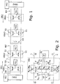
- Fig. 1 shows a power supply device with a two-pole bus line L , which is divided into bus segments BS by bus coupling elements (consumer bus coupling elements VBA1, ..., VBAn and feed bus coupling elements SBA1, SBA2 ).
- the bus line L can be interrupted (segmented into bus segments BS ) via switching elements S1 .
- the power bus here has a linear topology, for example, and is supplied with power from both sides of the power bus by a supply PS1, PS2 .
- the power bus is then preferably started up from the two supplies PS1, PS2 in sequence directions SR1, SR2 simultaneously from both sides of the power bus sequentially according to the method according to the invention described below.
- the first consumer bus coupling element VBA1 is directly connected to the first supply PS1 via the infeed bus coupling element SBA1 and the nth (last) consumer bus coupling element VBAn is directly connected to the further supply PS2 via a further infeed bus coupling element SBA2.
- the relevant bus segment BS' can be isolated by putting the neighboring consumer bus coupling elements (here: consumer bus coupling elements VBA2, VBA3) into the first operating state (see below) by opening the switching elements S1 ) to be brought.
- Consumers FE1, FE2 which are located on the consumer bus coupling elements VBA1, VBA2, which are located on the left of the disturbed bus segment BS ', can then use the first supply PS1, the consumers FE3 ... FEn which are located on the right of the disturbed bus segment BS' , are supplied via the further PS2 supply.
- switched-mode power supplies sometimes have very high input capacitances, which cause large inrush currents (rush-in currents).
- the current transients in turn lead to voltage drops on the power bus. Sequencing enables inrush current peaks to be avoided when an entire network of payloads (consumers) is switched on simultaneously.
- the loads and the bus segments are sequentially checked for faults during the bus setup and are connected to the power bus.
- a consumer bus coupling element VBA which enables the method according to the invention and thus the isolation of a disturbed bus segment and the (new) construction of the energy bus with an isolated bus segment, is shown in Fig. 2 shown.
- the consumer bus coupling element VBA comprises, in addition to the first switching element pair with the first switching elements S1 , a second switching element pair with second switching elements S2 , diodes and a control processor KP .
- the diodes are used to connect the control processor KP and a consumer FE to the bus line L.
- the control processor KP is connected in parallel to the test bridge branch PZ and is fed on one or both sides by the bus line L via the diodes. He switches on the consumer FE according to a certain predetermined criterion. This in Fig.
- the consumer bus coupling element VBA shown is in the basic state (switching elements S1, S2 are open).
- the consumer FE can be switched on by means of the second switching element S2 (first operating state).
- the bus line L is connected through (preferably after a time delay after closing the second switching elements S2) (second operating state).
- the first bus segment VBA1 in sequence direction SR1 is checked for faults.
- the bus coupling element preceding the bus segment serves as a reference bus coupling element for checking a bus segment. If the first bus segment is checked, the infeed bus coupling element serves as the reference bus coupling element RBA (SBA / RBA s. Fig. 7 ).
- RBA reference bus coupling element
- the voltage across the bridging resistors Due to the voltage drop across the bridging resistors, the voltage across the bridging resistors (test voltage) and thus on the control processor KP is lower than the minimum supply voltage during the testing process.
- the bridge voltages U +, U- or UR +, U R - measured by means of the bridge circuit ; U L +, U L - (depending on the direction of the sequence)
- any faults that may be present can be determined.
- the bus segment to be checked is supplied with energy at low resistance by closing the first switching elements S1 of the reference bus coupling element RBA.
- the first consumer bus coupling element VBA1 has an operating voltage which (due to voltage losses along the bus line) is generally lower than the supply voltage (typically 500 ... 900 VDC).
- the exceeding of the minimum operating voltage is then recognized and the consumer FE1 is switched on by closing the second switching element S2 of the first consumer bus coupling element VBA1 via a soft start.
- the next bus segment is checked.
- sequence direction SR1 one bus segment after the other is now checked completely autonomously and (if there is no fault) connected. At the same time and independently of this, this process can take place starting from the second feed PS2 in the sequence direction SR2. If a fault (eg short circuit) is detected in a bus segment BS ', the corresponding bus segment BS' is not switched on.
- a partial bus is then built up from each side (in each case from the supply PS1, PS2 to the disturbed bus segment BS ') so that the disturbed bus segment BS' remains isolated.
- the power bus and the consumers FE1, ... FEn connected to it can continue to be operated.
- This sequential check and connection of bus segments can be carried out when the bus is initially set up or after consumers have been switched off due to a short circuit during operation of the energy bus, as described below:
- the maximum possible current of the supplies PS1, PS2 and the supplies PS1, PS2 usually reduce the voltage in order to limit the current.
- the currents are usually actively limited and no fuses are used on the feed side of the feed voltage. The occurrence of a short circuit thus leads to a considerable voltage reduction, which leads to the connected loads being switched off by opening the second switching element S2 (undervoltage detection by the control processor KP).
- the energy supply device according to the invention preferably has local energy stores E in the consumers, which can maintain the entire operation for a few minutes.
- the method according to the invention works completely without a higher-level configuration and control and enables a safe and fast bus structure, especially during operation of the energy bus, without consumers having to be switched off, so that the functionality of the energy bus can also function after a bus segment BS is lost (unusable) due to a short circuit can be guaranteed.
- the consumer bus coupling elements VBA are designed so that the fault test can be carried out using a double Wheatstone bridge circuit.
- the consumer bus coupling elements VBA include three bridge resistors R B , which are connected in series with one another between the positive potential side and the negative potential side of the bus line L, and two bridging resistors R S , which each bridge a switching element S1 of the first switching element pair.
- Fig. 3 shows on the left a section of a first embodiment of a power supply device according to the invention with an infeed bus coupling element SBA and two consumer bus coupling elements VBA1, VBA2, which limit the bus segment BS to be checked.
- the consumer bus coupling element VBA1 which is closer to the infeed bus coupling element SBA (in the direction of the arrow, which represents the direction of the bus setup sequence), is used in the inventive check of the bus segment BS (selected here as an example) as a reference bus coupling element RBA that is removed from the infeed bus coupling element SBA located consumer bus coupling element serves as a test bus coupling element PBA .
- Components of the two consumer bus coupling elements RBA, PBA and the bus segment to be checked form the double bridge circuit required for the method according to the invention, which is shown in FIG Fig. 3 shown on the right.
- the bridge resistors R B (hatched) of the reference bus coupling element RBA form a reference bridge branch RZ and the bridge resistors R B (checked) of the test bus coupling element PBA together with the bridging resistors R S (dotted) of the reference bus coupling element RBA form a test bridge branch PZ .
- the bridge resistances R B of a certain consumer bus coupling element can be part of the test bridge branch PZ or the reference bridge branch RZ of the bridge circuit, depending on whether the bus segment preceding or following the respective consumer bus coupling element is to be checked.
- the consumer bus coupling element VBA1 can also be used as a test bus coupling element for testing the from the infeed bus coupling element SBA1 and the consumer bus coupling element VBA1 are used for limited bus segments.
- An indicator bridge branch IZ to the bus line L goes off between the outer bridge resistances and the middle bridge resistance.
- Each indicator bridge branch IZ comprises a voltage measuring device V.
- the in Fig. 2 and Fig. 3 The consumer bus coupling elements shown are each shown on both sides (in the direction along the bus line L) indicator bridge branches IZ each to the positive and negative potential side of the bus line L; this enables the test according to the invention to be carried out from both sequence directions SR1, SR2.
- the indicator bridge branches IZ are Bridge voltages U +, U-, measured. Using this high-impedance, potential-free voltage measurement, all relevant states of the bus line L can be recorded.
- the failure to differentiate between “open line” and “connection” is not critical here, because the method according to the invention is intended to prevent interference caused by connecting a “bad” line.
- the line status "Line open or connection of the line” is not rated as a fault. If the state “line open or connection of the line” is determined, the first switching elements S1 of the reference bus coupling element RBA are closed anyway. In the case of a merger the energy bus is then connected through (fully assembled). In the event of an open line, the sequencing stops automatically and the power bus can be set up (provided that both sides are fed in) from the other side to the disturbed point.
- the separate central diagnostic unit is responsible for checking whether all consumers are being supplied by the power bus.
- Fig. 4 the corresponding faults in the power bus are shown in the marked area (top left: earth fault + pole->earth; bottom left: earth fault - pole->earth; right short circuit between bus lines).
- R B For the values of the bridge resistances R B , R and for the values of the bridging resistances R S were assumed to be 3R.
- a ground in the infeed bus coupling element SBA serves as the reference potential.
- the reference potential to earth becomes imprecise over the distance.
- Fig. 6 therefore shows a section of a further embodiment of an energy supply device according to the invention with a temporary reference potential in the reference bridge branch RZ. This is achieved by dividing the middle bridge resistance and providing a further switching element S3 with which a ground connection can be established from the division point of the middle bridge resistance. If a consumer bus coupling element is used as the reference bus coupling element RBA, the further switching element S3 is closed and the temporary reference potential is thus generated. However, because of the regulations for insulation monitoring and the required high insulation values, this connection should not exist continuously during operation, so that the further switching element S3 is opened as soon as the corresponding Consumer bus coupling element is no longer used as a reference bus coupling element RBA.
- Fig. 7 a section of the energy supply device according to the invention is shown (control processor and supply have been omitted from the illustration for the sake of clarity), in which the structure of the infeed bus coupling element SBA used for the energy supply device according to the invention is shown.
- the infeed bus coupling element SBA can serve as a reference bus coupling element RBA for checking the first bus segment VBA1 (in the direction of the arrow).
- the bus segments can also be checked on both sides (in both sequence directions SR1, SR2).
- the infeed bus coupling element SBA ' must be compared to the in Fig. 7 embodiment shown by further first switching elements S1 ' , which are independent of the first switching elements S1, bridging resistors R' S and voltage measuring devices V 'are expanded, as in Fig. 8 shown.
- the in Fig. 8 In addition, the mean bridge resistance R B is divided and can be used to balance the voltage in the IT network at the same time.
- an insulation measurement (which, for example, is normatively prescribed for the IT network type of the control and safety technology) can be carried out in addition to the above-described sequential check of the individual bus segments using the bridge circuit.
- These insulation measurements are carried out at the feed point with certified, industrial insulation monitoring devices.
- the insulation monitoring is carried out via a supply sector (between two feed points) with the help of a higher-level diagnostic unit, which is responsible for locating the bus line at suitable points to perform the insulation measurements.
- each bus segment can be electrically isolated between the consumer bus coupling elements VBA during operation.
- the diagnostic unit carries out the standardized quantitative insulation measurement at regular intervals. For this purpose, the diagnostic unit switches a separation point to the fully operational supply sector, which is fed from both sides, starting from the location of the active insulation monitoring device. After each measurement, the separation point is switched to another bus segment. The earth fault can be localized by switching the separation point of the power bus. This procedure gives an overview of the insulation conditions over the entire supply sector with a local resolution of a segment.
- the diagnostic unit regularly calls up operating data from the operating processors of the consumer bus coupling elements. As a result, the accessibility of the consumer bus coupling elements is checked and a stop of the autonomous sequential connection due to an error in the segment to be connected again is recognized.
Description
Die Erfindung betrifft eine Energieversorgungseinrichtung zur Versorgung von Verbrauchern mit Energie umfassend eine erste Speisung, einen Energiebus mit einer 2-poligen Busleitung und Busankoppelelementen, wobei zwei Busankoppelelemente jeweils ein Bussegment der Busleitung begrenzen und wobei die Busankoppelelemente jeweils ein erstes Schaltelemente-Paar zur elektrischen Trennung der Busleitung umfassen. Die Erfindung betrifft auch ein Verfahren zum Betreiben einer Energieversorgungseinrichtung.The invention relates to an energy supply device for supplying consumers with energy, comprising a first supply, a power bus with a 2-pole bus line and bus coupling elements, two bus coupling elements each delimiting a bus segment of the bus line and the bus coupling elements each having a first pair of switching elements for the electrical separation of the Include bus line. The invention also relates to a method for operating an energy supply device.
Eine derartige Energieversorgungseinrichtung ist bekannt aus
Ein "Energiebus" bezeichnet eine aufeinanderfolgende Anordnung mehrerer Verbraucher entlang einer (2-poligen) Busleitung mit einer gemeinsamen Einspeisung. Der Energiebus der bekannten Energieversorgungseinrichtung umfasst neben der Busleitung auch Verbraucher-Busankoppelelemente, die entlang der Busleitung, also hintereinander, angeordnet sind und die Busleitung in Bussegmente unterteilt, sowie je nach Anzahl der Speisungen (Gleichspannungsquellen) Einspeise-Busankoppelelemente, über die Strom von der(den) Speisung(en) in die Busleitung eingespeist werden kann. Ein Energiebus kann eine lineare (offene Busleitung) oder eine ringförmige (geschlossene Busleitung) Topologie aufweisen. Der Stromfluss innerhalb des Energiebusses erfolgt bidirektional.An "energy bus" refers to a sequential arrangement of several consumers along a (2-pole) bus line with a common feed. In addition to the bus line, the energy bus of the known energy supply device also includes consumer bus coupling elements, which are arranged along the bus line, i.e. one behind the other, and which divide the bus line into bus segments, as well as, depending on the number of supplies (DC voltage sources), infeed bus coupling elements via which power is supplied from the ( the) feed (s) can be fed into the bus line. A power bus can have a linear (open bus line) or a ring-shaped (closed bus line) topology. The current flow within the energy bus is bidirectional.
Die Verbraucher-Busankoppelelemente weisen Schaltelemente zur elektrischen Trennung der Busleitung auf, so dass die Busankoppelelemente jeweils in einen Grundzustand und/oder einen ersten Betriebszustand, in dem die Busleitung durch das entsprechende Verbraucher-Busankoppelelement (Busankoppelelement mit Anschluss für Verbraucher) elektrisch unterbrochen ist, und in einen zweiten Betriebszustand, in dem die Bussegmente durch das entsprechende Verbraucher-Busankoppelelement elektrisch verbunden sind, gebracht werden können. Die Verbraucher-Busankoppelelemente sind i.A. funktionell unabhängig von den jeweiligen Verbrauchern. Es können auch Busankoppelelemente vorhanden sein, die keinen Verbraucher versorgen. Die Busankoppelelemente bilden Unterbrechungsstellen, an denen die Busleitung unterbrochen werden kann. Bei der Trennung/Unterbrechung der Busleitung handelt es sich um das Fehlen einer elektrisch leitenden Verbindung zwischen benachbarten Bussegmenten. Im Spannungspotentialbereich der Betriebsspannung wird hierdurch eine elektrische Isolierung erreicht.The consumer bus coupling elements have switching elements for the electrical separation of the bus line, so that the bus coupling elements are each in a basic state and / or a first operating state in which the bus line is electrically interrupted by the corresponding consumer bus coupling element (bus coupling element with connection for consumers), and can be brought into a second operating state in which the bus segments are electrically connected by the corresponding consumer bus coupling element. The consumer bus coupling elements are generally functionally independent of the respective consumers. There can also be bus coupling elements that do not supply a consumer. The bus coupling elements form interruption points at which the bus line can be interrupted. The disconnection / interruption of the bus line is the lack of an electrically conductive connection between adjacent bus segments. In this way, electrical insulation is achieved in the voltage potential range of the operating voltage.
Das Trennen der Busleitung in mehrere Busleitungsabschnitte (Bussegmente) durch die Verbraucher-Busankoppelelemente (elektrisches Unterbrechen der Busleitung an Unterbrechungsstellen) ermöglicht ein sequentielles Anschalten der Verbraucher und somit eine Reduzierung der auftretenden Stromspitzen beim Anschalten der Verbraucher (Busaufbau). Im Falle eines defekten Segments der Busleitung (z.B. Kurzschluss), werden die Verbraucher-Busankoppelelemente des betreffenden Versorgungssektors in den ersten Betriebszustand versetzt. Der Energiebus, bzw. der betroffene Versorgungssektor muss dann neu hochgefahren werden. Während dieser Zeit können die in diesem Versorgungssektor angeschlossenen Verbraucher nicht durch das Einspeise-Busankoppelelemente mit Energie versorgt werden.The separation of the bus line into several bus line sections (bus segments) by the consumer bus coupling elements (electrical interruption of the bus line at interruption points) enables the sequential connection of the Consumers and thus a reduction in the current peaks that occur when the consumers are switched on (bus structure). In the event of a defective segment of the bus line (eg short circuit), the consumer bus coupling elements of the relevant supply sector are put into the first operating state. The energy bus or the affected supply sector must then be restarted. During this time, the consumers connected in this supply sector cannot be supplied with energy by the infeed bus coupling element.
In der Leit- und Sicherungstechnik bei Bahnen werden spannungsführende Leitungen in der Außenanlage in aller Regel als IT-Netz ausgeführt (IT - isolee terre). Das heißt, die elektrischen Potentiale der spannungsführenden Leiter sind in etwa um das Erdpotential zentriert. Bei einem ersten Kurzschluss von einem Leiter nach Erdpotential verschiebt sich das Potential des anderen Leiters gegenüber dem Erdpotential und dem jeweils anderen Leiter, doch das System ist weiterhin uneingeschränkt funktionstauglich. Bei zwei spannungsführenden Leitern in einem IT Netz, gibt es im Wesentlichen drei Arten von Kurzschlüssen: Kurzschlüsse der einzelnen Leiter gegen Erdpotential und den direkten Kurzschluss der spannungsführenden Leiter.In the control and safety technology of railways, live lines in the outdoor system are usually implemented as IT networks (IT - isolee terre). This means that the electrical potentials of the live conductors are roughly centered around the earth potential. In the event of a first short circuit from one conductor to earth potential, the potential of the other conductor shifts compared to the earth potential and the respective other conductor, but the system is still fully functional. With two live conductors in an IT network, there are essentially three types of short circuits: Short circuits between the individual conductors and ground potential and the direct short circuit between the live conductors.
Bei herkömmlichen Energieversorgungseinrichtungen mit Energiebussen ist ein in der Versorgungsleitung zugeschaltetes Gerät (Erdschlusswächter, z.B. Bender UG145) vorgesehen, das eine eventuell auftretende Potentialverschiebung erkennt und einen Alarm generiert. Aktualisierte Vorschriften, insbesondere DIN EN 61557-8, verlangen heute eine Isolationsüberwachung mit Ausgabe eines Widerstandswertes. Diese Geräte (z.B. Bender iso685) arbeiten mit einem Verfahren, das mit Pulsen das IT-Netz beaufschlagt und aus der Netzantwort mit einem Prozessor den Isolationswert errechnet. Dieses aufwendige Verfahren ist für Netze mit hohen elektrischen Kapazitäten geeignet, doch ist das Verfahren langsam und kostenaufwendig. Zudem kann ohne aufwändige externe Sensorik nicht festgestellt werden wo genau im Energiebus die Störung aufgetreten ist.In conventional energy supply systems with energy buses, a device connected to the supply line (earth fault monitor, e.g. Bender UG145) is provided that detects any potential shift that may occur and generates an alarm. Updated regulations, especially DIN EN 61557-8, now require insulation monitoring with output of a resistance value. These devices (e.g. Bender iso685) work with a process that applies pulses to the IT network and uses a processor to calculate the insulation value from the network response. This complex process is suitable for networks with high electrical capacities, but the process is slow and costly. In addition, it is not possible to determine exactly where the fault occurred in the power bus without complex external sensors.
Aus
Darüber hinaus wird ein übergeordnetes Steuersystem benötigt, um mit den dezentralen Funktionseinheiten (Verbrauchern) mittels Datentelegramme Informationen auszutauschen.In addition, a higher-level control system is required in order to exchange information with the decentralized functional units (consumers) by means of data telegrams.
Es ist Aufgabe der Erfindung, eine Vorrichtung und ein Verfahren vorzuschlagen, wodurch einerseits ein Energiebus schnell und störungsfrei in Betrieb genommen werden kann und ein eventuell vorhandenes gestörtes Bussegment im Busaufbau schon gar nicht zugeschaltet wird.The object of the invention is to propose a device and a method whereby, on the one hand, a power bus can be put into operation quickly and without disruption and a possibly existing disturbed bus segment in the bus structure is not connected at all.
Durch die nachfolgend beschriebene Erfindung kann bei einem sich im Betrieb befindlichen Energiebus bei Eintritt einer Störung das gestörte Bussegment umgehend isoliert werden und der Energiebus bzw. die von der Störung nicht betroffenen Bussegmente können schnell und sicher wieder hochgefahren werden, so dass Ausfallzeiten der Verbraucher des Energiebusses minimiert oder sogar verhindert werden können.With the invention described below, when a fault occurs, the faulty bus segment can be immediately isolated when a power bus is in operation and the power bus or the bus segments not affected by the fault can be restarted quickly and safely, so that downtimes for the power bus consumers can be minimized or even prevented.
Diese Aufgabe wird erfindungsgemäß gelöst durch eine Energieversorgungsvorrichtung nach Anspruch 1 und ein Verfahren nach Anspruch 7.This object is achieved according to the invention by an energy supply device according to
Bei der erfindungsgemäßen Energieversorgungsvorrichtung dient zur Überprüfung des Bussegments eines der das zu überprüfende Bussegment begrenzenden Busankoppelelemente als Referenz-Busankoppelelement und das andere als Prüf-Busankoppelelement. Erfindungsgemäß umfassen die Busankoppelelemente jeweils drei Brückenwiderstände, die zwischen positiver Potentialseite und negativer Potentialseite der Busleitung miteinander in Serie geschaltet sind, und zwei Überbrückungswiderstände, die jeweils ein Schaltelement des ersten Schaltelement-Paars überbrücken. Die erfindungsgemäße Energieversorgungsvorrichtung weist zum Ermitteln von Leitungsstörungen eine doppelte Wheatstone'sche Brückenschaltung mit einem Referenzbrückenzweig, einem Prüfbrückenzweig und zwei Indikatorbrückenzweige, auf, wobei der Referenzbrückenzweig die drei Brückenwiderstände des Referenz-Busankoppelelements umfasst, und wobei der Prüfbrückenzweig die drei Brückenwiderstände des Prüf-Busankoppelelements sowie die Überbrückungswiderstände des Referenz-Busankoppelelements umfasst.In the energy supply device according to the invention, one of the bus coupling elements delimiting the bus segment to be checked is used as a reference bus coupling element and the other as a test bus coupling element to check the bus segment. According to the invention, the bus coupling elements each include three bridge resistors, which are between the positive potential side and the negative Potential side of the bus line are connected in series with one another, and two bridging resistors, which each bridge a switching element of the first switching element pair. The power supply device according to the invention has a double Wheatstone bridge circuit with a reference bridge branch, a test bridge branch and two indicator bridge branches to determine line faults, the reference bridge branch comprising the three bridge resistances of the reference bus coupling element, and the test bridge branch the three bridge resistances of the test bus coupling element and the bridging resistors of the reference bus coupling element.
Erfindungsgemäß ist eine doppelte Brückenschaltung in der Busleitung verschaltet, derart, dass die Elemente der doppelten Brückenschaltung auf zwei Busankoppelelemente aufgeteilt ist, so dass eines der Busankoppelelemente (nämlich das der Speisung elektrisch näher gelegene) als Referenz-Busankoppelelement dient. Mit der erfindungsgemäßen Schaltung können sowohl Kurzschlüsse innerhalb des Energiebusses als auch Kurzschlüsse gegen Erdpotential ermittelt werden. Der Begriff "Kurzschlüsse" beinhaltet sowohl niederimpedante Ableitungen, die den Nennstrom des Bussystems überschreiten, als auch relativ kleine Ströme gegen Erdpotential, die die Isolationsvorgaben überschreiten.According to the invention, a double bridge circuit is connected in the bus line in such a way that the elements of the double bridge circuit are divided between two bus coupling elements, so that one of the bus coupling elements (namely the one electrically closer to the supply) serves as a reference bus coupling element. With the circuit according to the invention, both short circuits within the power bus and short circuits to ground potential can be determined. The term "short circuits" includes both low-impedance discharge lines that exceed the rated current of the bus system and relatively small currents against earth potential that exceed the insulation specifications.
Das zu überprüfendes Bussegment wird durch ein vorgeschaltetes Busankoppelelement (Referenz-Busankoppelelement) und einem nachgeschalteten Busankoppelelement (Prüf-Busankoppelelement) begrenzt.The bus segment to be checked is limited by an upstream bus coupling element (reference bus coupling element) and a downstream bus coupling element (test bus coupling element).
Die Brückenwiderstände innerhalb jedes Referenz- oder Prüf-Brückenzweigs sind in Serie geschaltet und umfassen daher einen mittleren Brückenwiderstand und zwei äußere Brückenwiderstände.The bridge resistors within each reference or test bridge arm are connected in series and therefore comprise a middle bridge resistor and two outer bridge resistors.
Das Prinzip der doppelten Brückenschaltung basiert darauf, dass die Widerstandsverhältnisse im Referenzbrückenzweig gleich den Widerstandsverhältnissen im Prüfbrückenzweig sind. Dies kann erreicht werden, indem die Widerstandswerte so gewählt werden, dass der mittlere Brückenwiderstand und zwei äußere Brückenwiderstände den gleichen Widerstandswert aufweisen und dass der Wert des Überbrückungswiderstands gleich der Summe der Werte der Brückenwiderstände entspricht. Bei einer Busleitung mit einer hohen Anzahl an Busankoppelelementen kann es vorteilhaft sein, wenn die mittleren Brückenwiderstände größer gewählt werden als die äußeren Brückenwiderstände (s.u.). Die Widerstandswerte werden wie folgt gewählt: Verhältnis des Widerstandswerts des äußeren Brückenwiderstands einer Potentialseite zu der Summe der Widerstandswerte des mittleren und des äußeren Brückenwiderstands der anderen Potentialseite ist gleich dem Verhältnis des Widerstandswerts des Überbrückungswiderstands der einen Potentialseite zu der Summe der Widerstandswerte der Brückenwiderstände und dem Überbrückungswiderstand der anderen Potentialseite. Aufgrund der erfindungsgemäßen Verwendung einer Brückenmessmethode kann die Prüfung weitgehend unabhängig von der an den Busankoppelelementen anliegenden Spannung durchgeführt werden.The principle of the double bridge circuit is based on the fact that the resistance ratios in the reference bridge arm are the same as the resistance ratios in the test bridge arm. This can be achieved by choosing the resistance values so that the middle bridge resistance and two outer bridge resistances have the same resistance value and that the value of the bridging resistance is equal to the sum of the values of the bridge resistances corresponds. In the case of a bus line with a large number of bus coupling elements, it can be advantageous if the average bridge resistances are selected to be greater than the outer bridge resistances (see below). The resistance values are selected as follows: the ratio of the resistance value of the external bridge resistance on one potential side to the sum of the resistance values of the middle and external bridge resistance on the other potential side is equal to the ratio of the resistance value of the bridging resistance on one potential side to the sum of the resistance values of the bridge resistances and the bridging resistance the other potential side. Due to the inventive use of a bridge measurement method, the test can be carried out largely independently of the voltage applied to the bus coupling elements.
Die Doppelbrücke umfasst zwei Indikatorzweige, welche jeweils einen Prüfpunkt des Prüfbrückenzweigs mit einem Referenzpunkt des Referenzbrückenzweigs verbindet. Jeder Indikatorzweig umfasst eine Spannungsmesseinrichtung, welches den Potentialunterschied (Brückenspannung) zwischen dem jeweiligen Prüfpunkt und dem zugehörigen Referenzpunkt ermittelt. Der Prüfpunkt des ersten (bzw. zweiten) Indikatorzweigs liegt zwischen dem äußeren Brückenwiderstand des Prüf-Busankoppelelements und dem Überbrückungswiderstand des Referenz-Busankoppelelements der positiven (bzw. negativen) Potentialseite der Busleitung. Der Referenzpunkt des ersten (bzw. zweiten) Indikatorzweigs liegt zwischen dem mittleren und dem äußeren (an der positiven (bzw. negativen) Potentialseite der Busleitung angeordneten) Brückenwiderstand des Referenz-Busankoppelelements. Durch Messung der Brückenspannungen kann auf schnelle und einfache Weise ermittelt werden, ob eine Störung und welche Art der Störung vorliegt.The double bridge comprises two indicator branches, each of which connects a test point of the test bridge branch to a reference point of the reference bridge branch. Each indicator branch includes a voltage measuring device which determines the potential difference (bridge voltage) between the respective test point and the associated reference point. The test point of the first (or second) indicator branch lies between the external bridge resistance of the test bus coupling element and the bridging resistance of the reference bus coupling element on the positive (or negative) potential side of the bus line. The reference point of the first (or second) indicator branch lies between the middle and the outer (on the positive (or negative) potential side of the bus line) bridge resistance of the reference bus coupling element. By measuring the bridge voltages, it is possible to determine quickly and easily whether there is a fault and what type of fault is present.
Vorzugsweise umfasst die erfindungsgemäße Vorrichtung eine Vielzahl an Busankoppelelementen und daran angeschlossenen Verbrauchern, wobei jeweils zwei benachbarte Busankoppelelemente (Busankoppelelemente-Paare) eine doppelte Wheatstone'sche Brückenschaltung umfassen, mittels der das Bussegment zwischen dem Prüf-Busankoppelelement und dem Referenz-Busankoppelelement überprüft werden kann.The device according to the invention preferably comprises a plurality of bus coupling elements and consumers connected to them, two adjacent bus coupling elements (bus coupling element pairs) each comprising a double Wheatstone bridge circuit by means of which the bus segment can be checked between the test bus coupling element and the reference bus coupling element.
Die Verbraucher-Busankoppelelemente können von zwei Richtungen mit Energie versorgt werden, bspw. mittels zweier Speisungen. Die doppelten Brückenschaltungen sind vorzugsweise bzgl. der beiden Einspeiserichtungen symmetrisch aufgebaut, so dass jedes Busankoppelelement eines Busankoppelelemente-Paars sowohl als Prüf-Busankoppelelement als auch als Referenz-Busankoppelelement für das jeweilige zu überprüfende Bussegment fungieren kann (abhängig von der Speisungsrichtung). Jedes Bussegment kann dann also aus beiden Richtungen überprüft werden.The consumer bus coupling elements can be supplied with energy from two directions, for example by means of two supplies. The double bridge circuits are preferably constructed symmetrically with respect to the two feed directions, so that each bus coupling element of a bus coupling element pair can function both as a test bus coupling element and as a reference bus coupling element for the respective bus segment to be tested (depending on the feed direction). Each bus segment can then be checked from both directions.
Vorzugsweise wird die erfindungsgemäße Vorrichtung innerhalb eines Netzes der Netzform IT (isolée terre) verwendet, d.h. die elektrischen Potentiale der spannungsführenden Leiter der Busleitung haben definitionsgemäß keinen Bezug zum Erdpotential, kann aber in der Praxis mit symmetrischen hochohmigen Widerständen etwa um das Erdpotential zentriert werden. Diese Netzform wird vorzugsweise in der Bahntechnik, insbesondere in der Leit- und Sicherungstechnik verwendet.The device according to the invention is preferably used within a network of the network form IT (isolée terre), i. E. By definition, the electrical potentials of the live conductors of the bus line have no relation to the earth potential, but in practice they can be centered around the earth potential with symmetrical high-ohmic resistors. This type of network is preferably used in railway technology, especially in control and safety technology.
Das Prüf-Busankoppelelement ist ein Verbraucher-Busankoppelelement, d.h. ein Busankoppelelement, das dazu eingerichtet ist, dass ein Verbraucher angeschlossen werden kann. Es wird also das Bussegment überprüft, das für die Stromzuführung zu einem Verbraucher-Busankoppelelement führt, um sicherzustellen, dass ein an diesem Busankoppelelement angeschlossener Verbraucher sicher betrieben werden kann. Als Referenz-Busankoppelelement kann ein Speise-Busankoppelelement oder ein Verbraucher-Busankoppelelement dienen.The test bus coupling element is a consumer bus coupling element, i.e. a bus coupling element that is set up so that a consumer can be connected. The bus segment is checked, which leads to a consumer bus coupling element for the power supply in order to ensure that a consumer connected to this bus coupling element can be operated safely. A supply bus coupling element or a consumer bus coupling element can serve as the reference bus coupling element.
Das Verbraucher-Busankoppelelement umfasst Schaltelemente zur elektrischen Trennung der Busleitung, so dass die Busankoppelelemente jeweils in einen Grundzustand und/oder in einen ersten Betriebszustand, in dem die Busleitung durch das entsprechende Verbraucher-Busankoppelelement elektrisch unterbrochen ist, und in einen zweiten Betriebszustand, in dem die Bussegmente durch das entsprechende Verbraucher-Busankoppelelement elektrisch verbunden sind, gebracht werden können.The consumer bus coupling element comprises switching elements for the electrical separation of the bus line, so that the bus coupling elements are in a basic state and / or in a first operating state in which the bus line is electrically interrupted by the corresponding consumer bus coupling element, and in a second operating state in which the bus segments are electrically connected by the corresponding consumer bus coupling element, can be brought.
Vorzugsweise sind die Verbraucher zumindest teilweise mit einem lokalen Energiespeicher ausgestattet. Beim Überprüfen der Bussegmente kann sich der Verbraucher aus dem lokalen Energiespeicher mit Energie versorgen bis die Prüfung abgeschlossen ist. Auf diese Weise wird der Betrieb der Verbraucher nicht unterbrochen.The consumers are preferably at least partially equipped with a local energy store. When checking the bus segments, the consumer can be supplied with energy from the local energy store until the check is completed. In this way the operation of the consumer is not interrupted.
Bei einer besonders vorteilhaften Ausführungsform ist die Busleitung mit einer weiteren Speisung elektrisch verbunden. Die Verbraucher-Busankoppelelemente können von verschiedenen Richtungen über verschiedene Speisungen mit Energie versorgt werden. Hierdurch wird ein beidseitiges Einspeisen von Energie auch bei einer linearen Bus-Topologie ermöglicht.In a particularly advantageous embodiment, the bus line is electrically connected to a further supply. The consumer bus coupling elements can be supplied with energy from different directions via different feeds. This enables energy to be fed in on both sides, even with a linear bus topology.
Bei einer speziellen Ausführungsform weist der mittlere Brückenwiderstand der in Serie geschalteten Brückenwiderstände eine höheren Widerstandswert auf als die beiden äußeren Brückenwiderstände, insbesondere einen um einen Faktor 1,2 bis 1,5 höheren Widerstandswert. Hierdurch kann eine bessere Symmetrierung der Doppelbrücke erreicht werden.In a special embodiment, the mean bridge resistance of the series-connected bridge resistors has a higher resistance value than the two outer bridge resistances, in particular a resistance value that is 1.2 to 1.5 times higher. This allows better balancing of the double bridge to be achieved.
In der Leit- und Sicherungstechnik kann in den IT-Netzen- in Abhängigkeit der Sicherheitsbetrachtung - eine Isolationsmessung vorgeschrieben werden, diese dient zum Erkennen eines ersten Fehlers bevor ein zweiter Fehler eintritt.In control and safety technology, an insulation measurement can be prescribed in the IT networks - depending on the safety consideration - this serves to detect a first error before a second error occurs.
Zur Durchführung der Isolationsmessung ist es vorteilhaft, wenn ein oder mehrere Isolationsüberwachungsgerät(e) zur Durchführung von Isolationsmessungen an den Bussegmenten und/oder den einzelnen Einspeise-Busankoppelelementen und eine Diagnoseeinheit zur Steuerung der Isolationsmessungen vorhanden sind. Die zentrale Diagnoseeinheit zur Steuerung der Isolationsmessungen kann funktionell für einen oder mehrere Versorgungssektoren zuständig sein. Mit der zentralen Diagnoseeinheit und den verteilten Isolationsüberwachungsgeräten können gezielt quantitative Messungen an ausgewählten Bussegmenten durchgeführt werden. Durch die Segmentierung des Energiebusses können bei beidseitig gespeisten Energiebussen die Isolationsmessungen während des Betriebs des Energiebusses durchgeführt werden. Dazu wird ein zu vermessender Versorgungssektor des Energiebusses vom im Betrieb befindlichen Energiebus getrennt (Unterbrechen eines Bussegments an den beiden begrenzenden Verbraucher-Busankoppelelementen) und geprüft. Die Durchführung dieser Messungen während des Betriebs des Energiebusses ist besonders vorteilhaft, da diese Messungen sehr zeitaufwändig sein können.To carry out the insulation measurement, it is advantageous if one or more insulation monitoring devices for carrying out insulation measurements on the bus segments and / or the individual infeed bus coupling elements and a diagnostic unit for controlling the insulation measurements are available. The central diagnostic unit for controlling the insulation measurements can functionally be responsible for one or more supply sectors. With the central diagnostic unit and the distributed insulation monitoring devices, quantitative measurements can be carried out on selected bus segments. Due to the segmentation of the energy bus, the insulation measurements can be carried out during operation of the energy bus in the case of energy buses fed on both sides. For this purpose, a supply sector of the energy bus to be measured is separated from the energy bus in operation (interruption of a bus segment at the two limiting consumer bus coupling elements) and checked. Performing these measurements during operation of the power bus is particularly advantageous as these measurements can be very time consuming.
Falls eine Diagnoseeinheit für den Betrieb des Energiebusses eingesetzt wird, ist diese vorzugsweise zentralisiert und Teil eines übergeordneten Systems für den Betrieb der Leit- und Sicherungstechnik. Die verteilten Geräte zur Isolationsmessung (Isolationsüberwachungsgeräte) können aber müssen nicht Teil einer Einspeisevorrichtung sein (insbesondere wenn mehrere Speisungen vorgesehen sind). Die Einspeiseeinrichtung umfasst vorzugsweise mindestens folgende Teilsysteme: eine Gleichspannungsquelle (Speisung), ein erstes Referenz-Busankoppelelement, einen Kontrollprozessor zur Kontrolle des Einspeise-Busankoppelelementes und einen Betriebsprozessor zur Steuerung der Gleichspannungsquelle und das Isolationsüberwachungsgerät (falls vorhanden). Die zentrale Diagnoseeinheit kommuniziert über ein parallel geführtes Datennetz mit allen erreichbaren Einspeise-Busankoppelelemente und Verbraucher-Busankoppelelemente in einem bestimmten Versorgungssektor (Versorgungssektor = Energieversorgungsbereich innerhalb des Energiebusses mit einer oder mehreren Speisungen und einer Vielzahl von Verbraucher-Busankoppelelemente und den dazwischenliegenden Bussegmenten).If a diagnostic unit is used to operate the power bus, it is preferably centralized and part of a higher-level system for operating the control and safety technology. The distributed devices for insulation measurement (insulation monitoring devices) cannot, however, be part of a feed device (especially if several feeds are provided). The feed device preferably comprises at least the following subsystems: a DC voltage source (supply), a first reference bus coupling element, a control processor to control the feed bus coupling element and an operating processor to control the DC voltage source and the insulation monitoring device (if present). The central diagnostic unit communicates via a parallel data network with all available infeed bus coupling elements and consumer bus coupling elements in a certain supply sector (supply sector = energy supply area within the energy bus with one or more supplies and a large number of consumer bus coupling elements and the bus segments in between).
Vorzugsweise ist mindestens ein Verbraucher an einem der Busankoppelelemente angeschlossen, wobei es sich bei den Verbrauchern vorzugsweise um Komponenten der Leit- und Sicherungstechnik, insbesondere um Feldelemente handelt. Feldelemente sind Elemente, die entlang einer Schienenverkehrsstrecke angeordnet sind, insbesondere Weichen, Signale usw. Die Feldelemente umfassen vorzugsweise jeweils eine Weitbereichs-Stromversorgung, diverse Elektronik mit Prozessoren und einen Anschluss an das Datenkommunikationsnetzwerk.At least one consumer is preferably connected to one of the bus coupling elements, the consumers preferably being components of control and safety technology, in particular field elements. Field elements are elements that are arranged along a rail traffic route, in particular switches, signals, etc. The field elements preferably each include a wide-range power supply, various electronics with processors and a connection to the data communication network.
Bei einer speziellen Ausführungsform der erfindungsgemäßen Energieversorgungseinrichtung ist die erste Speisung die einzige Speisung des Energiebusses. Dabei kann beispielsweise lediglich das erste Verbraucher-Busankoppelelement direkt (also ohne Zwischenschaltung eines weiteren mit einem Verbraucher bestückten Verbraucher-Busankoppelelements) mit der ersten Speisung bzw. dem Einspeise-Busankoppelelement verbunden sein. Die weiteren Verbraucher-Busankoppelelemente schließen sich dann jeweils an das vorangehende Verbraucher-Busankoppelelement an (Einspeisepunkt an einem der beiden Enden des Energiebusses). Die Einspeisung von Strom erfolgt hier nur an einer einzigen Stelle. Bei einer Störung werden der ganze Energiebus oder Teile des Busses stromlos. Es ist jedoch auch möglich, die erste Speisung an einer beliebigen Stelle des Energiebusses, z.B. zwischen zwei Verbraucher-Busankoppelelementen anzuordnen. Die Einspeisung von Energie in die Busleitung erfolgt dann von der einzigen Speisung in zwei Richtungen.In a special embodiment of the energy supply device according to the invention, the first supply is the only supply to the energy bus. For example, only the first consumer bus coupling element can be connected directly (that is, without the interposition of a further consumer bus coupling element equipped with a consumer) to the first supply or the infeed bus coupling element. The further consumer bus coupling elements then each connect to the preceding consumer bus coupling element on (feed point at one of the two ends of the energy bus). Electricity is fed in here at just one point. In the event of a fault, the entire power bus or parts of the bus are de-energized. However, it is also possible to arrange the first supply at any point on the energy bus, for example between two consumer bus coupling elements. Energy is fed into the bus line from the single feed in two directions.
Eine weitere Ausführungsform der erfindungsgemäßen Stromversorgungseinrichtung sieht vor, dass das erste und das n-te (letzte) Verbraucher-Busankoppelelement direkt mit der ersten Speisung verbunden sind, so dass der Energiebus eine ringförmige Topologie aufweist. Diese Ausführungsform ermöglicht eine beidseitige Einspeisung von Strom mittels nur einer Speisung. Hierdurch können trotz Auftreten eines Fehlers in einem Segment der Busleitung sämtliche Verbraucher mit Energie versorgt werden (Fehlerbehebung erster Stufe).Another embodiment of the power supply device according to the invention provides that the first and the n-th (last) consumer bus coupling element are connected directly to the first supply so that the power bus has a ring-shaped topology. This embodiment enables electricity to be fed in on both sides by means of just one feed. In this way, despite the occurrence of an error in a segment of the bus line, all consumers can be supplied with energy (first stage troubleshooting).
Vorzugsweise ist die Busleitung mit einer weiteren (also einer zweiten, ev. auch einer dritten, vierten usw.) Speisung elektrisch verbunden (dritte und fünfte Ausführungsform).The bus line is preferably electrically connected to a further (that is, a second, possibly also a third, fourth, etc.) supply (third and fifth embodiment).
Bei der dritten vorteilhaften Ausführungsform ist einer der Verbraucher-Busankoppelelemente, vorzugsweise das n-te Verbraucher-Busankoppelelement direkt mit der weiteren (insbesondere der zweiten) Speisung verbunden. Bei dieser Ausführungsform weist der Energiebus eine lineare Topologie mit einer beidseitigen Einspeisung von Energie mittels zweier Speisungen auf.In the third advantageous embodiment, one of the consumer bus coupling elements, preferably the nth consumer bus coupling element, is directly connected to the further (in particular the second) supply. In this embodiment, the power bus has a linear topology with a bilateral feed of energy by means of two feeds.
Zum Zwecke einer erhöhten Verfügbarkeit ist es vorteilhaft, wenn mehr als eine weitere Speisung (also insgesamt mehr als zwei Speisungen) mit der Busleitung elektrisch verbunden sind (dritte und fünfte Ausführungsform).For the purpose of increased availability, it is advantageous if more than one further feed (that is to say a total of more than two feeds) are electrically connected to the bus line (third and fifth embodiment).
Ab dieser Ausführungsform kann eine Fehlerbehebung erster und fallweiser zweiter Stufe realisiert werden.As of this embodiment, first and occasionally second stage troubleshooting can be implemented.
Besonders vorteilhaft ist es, wenn eine Buskoppeleinheit vorhanden ist, die den ersten Energiebus mit einem zweiten Energiebus koppelt. Eine Buskoppeleinheit verfügt über mindestens vier Anschlüsse (Kopplung von zwei Energiebussen) und kann beliebige elektrisch zulässige Stellungen (also insbesondere kurzschlussfreie paarweise Kopplungen der zweipoligen Busleitungen) einnehmen, auch Mehrfachstellungen .It is particularly advantageous if there is a bus coupling unit which couples the first power bus to a second power bus. A bus coupling unit has at least four connections (coupling of two power buses) and can assume any electrically permissible positions (i.e. in particular short-circuit-free paired connections of the two-pole bus lines), including multiple positions.
Über dieselbe Koppeleinheit können auch mehr als zwei Energiebusse miteinander gekoppelt werden. Darüber hinaus kann die Energieversorgungseinrichtung auch mehrere Koppeleinheiten umfassen, die jeweils mindestens zwei Energiebusse miteinander koppeln.More than two power buses can be coupled to one another via the same coupling unit. In addition, the energy supply device can also comprise a plurality of coupling units which each couple at least two energy buses to one another.
Im Falle einer ringförmigen Topologie des/der Energiebusses/busse teilt die Buskoppeleinheit die ringförmige(n) Busleitung(en) benachbarter Energiebusse jeweils in einen ersten Leitungsabschnitt und einen zweiten Leitungsabschnitt. Bei Auftreten einer Störung sowohl im ersten Leitungsabschnitt als auch im zweiten Leitungsabschnitt eines Energiebusses können dann die durch die buseigene Speisung nicht mehr versorgbaren Verbraucher durch die Speisung des zweiten Busses versorgt werden (Fehlerbehebung zweiter Stufe). Die Buskoppeleinheit umfasst dazu bspw. weitere Schaltelemente zum elektrischen Verbinden des nicht mehr versorgbaren Leitungsabschnitts des ersten Energiebusses mit dem zweiten Energiebus.In the case of a ring-shaped topology of the energy bus (s), the bus coupling unit divides the ring-shaped bus line (s) of adjacent energy buses into a first line section and a second line section. If a fault occurs in the first line section as well as in the second line section of an energy bus, the consumers that can no longer be supplied by the bus's own supply can then be supplied by the supply of the second bus (second level troubleshooting). For this purpose, the bus coupling unit comprises, for example, further switching elements for electrically connecting the line section of the first power bus that can no longer be supplied to the second power bus.
Eine vierte Ausführungsform sieht dabei vor, dass der erste und der zweite Energiebus (vorzugsweise sämtliche Energiebusse der Energieversorgungseinrichtung) eine ringförmige Topologie aufweisen. Diese Ausführungsform ist insbesondere vorteilhaft, wenn große Distanzen mit hoher Verfügbarkeit überwunden werden müssen, bspw. zur Verbindung zweier Versorgungsnetze.A fourth embodiment provides that the first and the second power bus (preferably all power buses of the power supply device) have an annular topology. This embodiment is particularly advantageous when large distances have to be covered with high availability, for example to connect two supply networks.
Eine fünfte und sechste Ausführungsform sieht vor, dass der erste und der zweite Energiebus (vorzugsweise sämtliche Energiebusse der Stromversorgungseinrichtung) jeweils eine lineare Topologie aufweisen. Diese Ausführungsform kann vorteilhaft zur Verbindung großer Gleisfelder verwendet werden.A fifth and sixth embodiment provides that the first and the second power bus (preferably all power buses of the power supply device) each have a linear topology. This embodiment can be used advantageously for connecting large track fields.
Bei einer siebten Ausführungsform sind ein Energiebus mit ringförmiger Topologie und ein Energiebus mit linearer Topologie durch die Buskoppeleinheit miteinander gekoppelt.In a seventh embodiment, a power bus with a ring-shaped topology and a power bus with a linear topology are coupled to one another by the bus coupling unit.
Vorzugsweise weist das Verbraucher-Busankoppelelement sowohl an der negativen als auch an der positiven Potentialseite der Busleitung jeweils ein erstes Schaltelement zur elektrischen Trennung der Busleitung und ein zweites Schaltelement zum Zuschalten des Verbrauchers zum Energiebus auf, wobei die ersten Schaltelemente Teil der Busleitung und die zweiten Schaltelemente Teil einer im Verbraucher-Busankoppelelement integrierten, von der Busleitung zum Verbraucher führenden Versorgungsleitung sind.The consumer bus coupling element preferably has a first switching element for electrically isolating the bus line and a second switching element for connecting the consumer to the power bus on both the negative and the positive potential side of the bus line, the first switching elements being part of the bus line and the second switching elements Part of a supply line that is integrated in the consumer bus coupling element and leading from the bus line to the consumer.
Die Erfindung betrifft auch ein Verfahren zum Betreiben einer Energieversorgungseinrichtung nach einem der vorhergehenden Ansprüche, wobei das Verfahren folgende Verfahrensschritte umfasst:
- a) Auswahl eines zu überprüfenden Bussegments, wobei am Referenz-Busankoppelelement des zu überprüfenden Bussegments eine Betriebsspannung anliegt und wobei die ersten Schaltelemente des Referenz-Busankoppelelements des zu überprüfenden Bussegments geöffnet sind, so dass am Prüf-Busankoppelelement eine gegenüber der Betriebsspannung reduzierte Prüfspannung anliegt;
- b) Messung einer ersten Brückenspannung und einer zweiten Brückenspannung der doppelten Wheatstone'schen Brückenschaltung;
- c) Prüfen in Abhängigkeit von den gemessenen Brückenspannungen, ob eine Störung vorliegt;
- d) Falls keine Störung vorliegt wird das Prüf-Busankoppelelement zum Energiebus zugeschaltet indem die Schaltelemente des ersten Schaltelement-Paars des Referenz-Busankoppelelements geschlossen werden, und die Schritte a) - d) werden wiederholt, wobei ein nachfolgendes Bussegment als das zu überprüfende Bussegment ausgewählt wird;
- e) Falls eine Störung vorliegt, wird das Verfahren gestoppt und somit das Prüf-Busankoppelelement nicht zum Energiebus zugeschaltet und keine weiteren Bussegmente überprüft.
- a) Selection of a bus segment to be checked, with an operating voltage being applied to the reference bus coupling element of the bus segment to be checked and the first switching elements of the reference bus coupling element of the bus segment to be checked being open, so that a test voltage that is reduced compared to the operating voltage is applied to the test bus coupling element;
- b) measurement of a first bridge voltage and a second bridge voltage of the double Wheatstone bridge circuit;
- c) Check depending on the measured bridge voltages whether there is a fault;
- d) If there is no fault, the test bus coupling element is connected to the power bus by closing the switching elements of the first switching element pair of the reference bus coupling element, and steps a) - d) are repeated, with a subsequent bus segment selected as the bus segment to be checked becomes;
- e) If there is a fault, the process is stopped and the test bus coupling element is not connected to the power bus and no further bus segments are checked.
Das Verfahren mit den Schritten a) - e) läuft in allen Richtungen abgehend von den Stromversorgungen ab. Das heißt, auf einer Strecke mit Störstelle stoppt das Verfahren auch von der anderen Versorgungsrichtung. Dadurch wird die Störstelle isoliert, wobei trotzdem alle Busankoppelelemente mit Energie versorgt werden.The method with steps a) - e) runs in all directions starting from the power supplies. This means that on a route with a fault, the process also stops from the other supply direction. This will make the Interference point isolated, with all bus coupling elements still being supplied with energy.
Das erfindungsgemäße Verfahren ermöglicht die Prüfung einzelner Bussegmente eines Energiebusses auf Störungen (Kurzschlüsse) ohne die Verbraucher des Energiebusses außer Betrieb zu nehmen und ein zeitnahes Zuschalten der überprüften Busankoppelelemente.The method according to the invention enables individual bus segments of an energy bus to be checked for faults (short circuits) without taking the consumers of the energy bus out of operation and to switch on the checked bus coupling elements in a timely manner.
Als "nachfolgendes Bussegment" wird ein Bussegment bezeichnet, welches elektrisch auf der der Speisung abgewandten Seite des zuvor überprüften Bussegments angeordnet ist.A bus segment which is electrically arranged on the side of the previously checked bus segment facing away from the supply is referred to as a "subsequent bus segment".
Diejenigen Verbraucher-Busankoppelelemente, für die keine Störung für die dem Verbraucher-Busankoppelelement vorgeschalteten Bussegmente ermittelt wurde, werden erfindungsgemäß nacheinander zugeschaltet. Falls die Prüfung des Bussegments negativ ausfällt (also eine Störung festgestellt wird), wird das entsprechende Prüf-Busankoppelelement (dem Bussegment nachgeschaltetes Verbraucher-Busankoppelelement) nicht zugeschaltet. Der Energiebus kann dann jedoch in dem Umfang, in dem bis dahin die Verbraucher-Busankoppelelemente zugeschaltet wurden, betrieben werden.Those consumer bus coupling elements for which no fault was determined for the bus segments upstream of the consumer bus coupling element are switched on one after the other according to the invention. If the test of the bus segment turns out negative (i.e. a fault is detected), the corresponding test bus coupling element (consumer bus coupling element connected downstream of the bus segment) is not switched on. The power bus can then, however, be operated to the extent that the consumer bus coupling elements have been connected up to that point.
Das Anlegen der Betriebsspannung erfolgt durch die Speisung. Während der erfindungsgemäßen Prüfung sind die Schaltelemente des ersten Schaltelemente-Paars des jeweiligen Prüf-Busankoppelelements geöffnet, so dass der Prüfbrückenzweig bestromt wird. Das Prüf-Busankoppelelement befindet sich dann im Grundzustand, d.h. das Prüf-Busankoppelelement trennt die Busleitung elektrisch und an das Prüf-Busankoppelelement anzuschließende Verbraucher sind vom Prüf-Busankoppelelement elektrisch getrennt. Auf diese Weise kann das Prüf-Busankoppelelement zur Prüfung des vorangehenden Bussegments verwendet werden, ohne dass ein an dem Prüf-Busankoppelelement angeschlossener Verbraucher angeschaltet wird (aufgrund der gegenüber der Betriebsspannung reduzierten anliegenden Prüfspannung). Die Prüfspannung beträgt vorzugsweise 1/3 der Betriebsspannung. Die Widerstände der Brückenschaltung sind so gewählt, dass die Prüfspannung stets kleiner ist als die minimale Betriebsspannung des Verbraucher-Busankoppelelements ist.The operating voltage is applied by the supply. During the test according to the invention, the switching elements of the first switching element pair of the respective test bus coupling element are open, so that the test bridge branch is energized. The test bus coupling element is then in the basic state, ie the test bus coupling element electrically isolates the bus line and loads to be connected to the test bus coupling element are electrically isolated from the test bus coupling element. In this way, the test bus coupling element can be used to test the preceding bus segment without a consumer connected to the test bus coupling element being switched on (due to the test voltage being reduced compared to the operating voltage). The test voltage is preferably 1/3 of the operating voltage. The resistances of the bridge circuit are chosen so that the test voltage is always lower than the minimum operating voltage of the consumer bus coupling element.
Bei der erfindungsgemäßen Störungsprüfung ist der Energiebus elektrisch weitgehend entkoppelt, so dass nur ein Teil der Busankoppelelemente, nämlich von der Speisung ausgehend bis zum Referenz-Busankoppelelement, durch die Speisung mit Energie versorgt wird.In the fault check according to the invention, the power bus is largely electrically decoupled, so that only some of the bus coupling elements, namely from the feed to the reference bus coupling element, are supplied with energy by the feed.
Eine Störung wird vorzugsweise dann festgestellt, wenn
- i) die erste Brückenspannung und die zweite Brückenspannung einen positiven Grenzwert überschreiten, oder
- ii) die erste Brückenspannung und die zweite Brückenspannung einen negativen Grenzwert unterschreiten, oder
- iii) wenn die erste Brückenspannung einen negativen Grenzwert unterschreitet und die zweite Brückenspannung einen positiven Grenzwert überschreitet.
- i) the first bridge voltage and the second bridge voltage exceed a positive limit value, or
- ii) the first bridge voltage and the second bridge voltage fall below a negative limit value, or
- iii) if the first bridge voltage falls below a negative limit value and the second bridge voltage exceeds a positive limit value.
Als "erste Brückenspannung" wird die Spannung zwischen Referenzpunkt und Prüfpunkt des Indikatorbrückenzweigs auf der positiven Potentialseite bezeichnet.The voltage between the reference point and test point of the indicator bridge branch on the positive potential side is referred to as the "first bridge voltage".
Als "zweite Brückenspannung" wird die Spannung zwischen Referenzpunkt und Prüfpunkt des Indikatorbrückenzweigs auf der negativen Potentialseite bezeichnet.The "second bridge voltage" is the voltage between the reference point and the test point of the indicator bridge branch on the negative potential side.
Im Fall von i) liegt ein Kurzschluss gegen Erde auf der negativen Potentialseite des Energiebusses vor. Im Fall von ii) liegt ein Kurzschluss gegen Erde auf der positiven Potentialseite des Energiebusses vor. Im Fall von iii) liegt ein Leitungskurzschluss zwischen der negativen und der positiven Potentialseite des Energiebusses vor.In the case of i) there is a short circuit to earth on the negative potential side of the power bus. In the case of ii) there is a short circuit to earth on the positive potential side of the energy bus. In the case of iii) there is a short circuit between the negative and the positive potential side of the power bus.
Wenn die erste Brückenspannung einen positiven Grenzwert überschreitet und die zweite Brückenspannung einen negativen Grenzwert unterschreitet, liegt entweder eine offene Leitung oder ein Zusammenschluss der Busleitungen vor (Systembedingt kann nicht zwischen einer offenen Leitung und dem Zusammenschluss unterschieden werden). Der Zusammenschluss ist die letzte Messung, wenn das gleiche Bussegment von beiden Seiten gleichzeitig geprüft wird (falls der Energiebus von zwei Seiten aufgebaut wird). Bei einer offenen Leitung oder einem Zusammenschluss handelt es sich nicht um eine Störung. Ein solcher Zustand kann zwar erfasst werden, soll aber nicht das Schließen der Schaltelemente des ersten Schaltelement-Paares verhindern (s.
Bei einer ersten Variante wird das erfindungsgemäße Verfahren zum Hochfahren des Energiebusses (Busaufbau) eingesetzt, wobei das Zuschalten der Busankoppelelemente (Schritt d)) sequentiell ausgehend von der Speisung erfolgt.In a first variant, the method according to the invention is used to start up the energy bus (bus structure), the connection of the bus coupling elements (step d)) taking place sequentially starting from the supply.
Beim Busaufbau sind zuerst alle Verbraucher-Busankoppelelemente im Grundzustand. Damit ist der Bus an allen Segmenten getrennt. Ausgangspunkt ist also ein stromloser Energiebus, bei dem alle ersten Schaltelement-Paare geöffnet sind. Ausgehend von der Speisung werden die Bussegmente nacheinander auf Störungen geprüft und das entsprechende Prüf-Busankoppelelement und somit auch das zugehörige (dem Prüfankoppelelement vorangehende) Bussegment wird (falls keine Störung festgestellt wird) zum Energiebus zugeschaltet.When the bus is set up, all consumer bus coupling elements are first in the basic state. The bus is thus separated on all segments. The starting point is therefore a currentless power bus in which all the first pairs of switching elements are open. Starting from the power supply, the bus segments are checked for faults one after the other and the corresponding test bus coupling element and thus also the associated bus segment (preceding the test coupling element) is connected to the power bus (if no fault is detected).
Das erfindungsgemäße Verfahren verhindert, dass ein kurzschlussbehaftetes Bussegment zugeschaltet wird und damit der ganze Energiebus zusammenbricht. Es wird also sichergestellt, dass beim Aufbau des Energiebusses nur intakte Bussegmente zugeschaltet werden.The method according to the invention prevents a short-circuited bus segment from being switched on and thus the entire power bus from collapsing. This ensures that only intact bus segments are connected when the energy bus is set up.
Diese Messung ist qualitativ und genügt gegebenenfalls nicht den normativen Vorgaben für die IT-Netzform (DIN N 61557-8). Um das erfindungsgemäße Verfahren bei IT-Netzform in der Leit- und Sicherungstechnik zu verwenden, wird daher zusätzlich ein oder mehrere Isolationsüberwachungsgeräte verwendet, welche unabhängig von der erfindungsgemäßen Störungsprüfung den mit einem Kurzschluss einhergehenden Potentialverschiebungen und/oder Ableitströme quantitativ erfasst. Die Ausgabe ist ein Isolationswiderstand des Energiebusses gegenüber Erdpotential.This measurement is qualitative and may not meet the normative requirements for the IT network configuration (DIN N 61557-8). In order to use the method according to the invention with IT network form in control and safety technology, one or more insulation monitoring devices are therefore additionally used, which quantitatively records the potential shifts and / or leakage currents associated with a short circuit independently of the inventive fault test. The output is an insulation resistance of the energy bus to earth potential.
Durch das erfindungsgemäße Verfahren können beim Busaufbau Bussegmente mit Kurzschlüssen zwischen den Busleitungen und Kurzschlüsse gegen Erdpotential ermittelt werden.With the method according to the invention, bus segments with short circuits between the bus lines and short circuits to ground potential can be determined when building the bus.
Alternativ oder zusätzlich kann das Verfahren während des Betriebs des Energiebusses eingesetzt werden nachdem eine Störung im Betrieb, insbesondere ein Kurzschluss, und eine Isolierung des von der Störung im Betrieb betroffenen Bussegments im Energiebus festgestellt wurde.Alternatively or additionally, the method can be used during the operation of the power bus after a fault in operation, in particular a Short circuit and insulation of the bus segment in the power bus affected by the malfunction was found.
Vorzugsweise wird die Störung im Betrieb durch Detektion einer Unterspannung an einem oder mehreren Verbraucher-Busankoppelelementen detektiert. Bei den Verbraucher-Busankoppelelementen, bei denen die Unterspannung detektiert wurde, wird dann durch Öffnen der zweiten Schaltelemente der Verbraucher vom Energiebus automatisch getrennt. Die Isolierung des von der Störung im Betrieb betroffenen Bussegments erfolgt durch Öffnen der ersten Schaltelemente automatisch.The malfunction is preferably detected during operation by detecting an undervoltage on one or more consumer bus coupling elements. With the consumer bus coupling elements in which the undervoltage was detected, the consumer is then automatically disconnected from the power bus by opening the second switching element. The bus segment affected by the malfunction in operation is automatically isolated by opening the first switching elements.
Wenn während des Betriebs des Energiebusses eine Überlast durch Kurzschluss zwischen Busleitungen auftritt, wird in der Speisung durch die Strombegrenzung der Spannungsversorgungen die Spannung reduziert und/oder es entsteht durch die hohen Ströme auf langen Leitungen ein großer Spannungsabfall. Am Verbraucher-Busankoppelelement entsteht eine Unterspannung. Das Verbraucher-Busankoppelelement reagiert sofort selbständig lokal und öffnet die ersten Schaltelemente. Damit wird der Bus an einem oder meist an mehreren Orten unterbrochen (zerteilt in mehrere spannungslose Bussegmente). Ausgehend von diesem Schaltungszustand wird das erfindungsgemäße Verfahren durchgeführt, so dass die Bussegmente, bei denen keine Störung festgestellt wird, sequentiell wieder zugeschaltet werden können.If an overload occurs due to a short circuit between bus lines during operation of the power bus, the voltage in the supply is reduced by the current limitation of the power supplies and / or the high currents on long lines result in a large voltage drop. An undervoltage occurs on the consumer bus coupling element. The consumer bus coupling element reacts immediately and independently locally and opens the first switching elements. This means that the bus is interrupted at one or mostly at several locations (divided into several voltage-free bus segments). The method according to the invention is carried out on the basis of this switching state so that the bus segments in which no fault is detected can be switched on again sequentially.
Ausgehend vom letzten noch geschlossenen ersten Schaltelemente-Paar (also vom letzten noch bestromten Bussegment) beginnt (vorzugsweise beidseitig) wieder das sequentielle Zuschalten der Bussegmente (Busaufbau). Das Zuschalten wird vor der Kurzschlussstelle gestoppt, so dass das gestörte Bussegment nicht zugeschaltet wird. Das Prüfen und Zuschalten erfolgt vorzugsweise beidseitig. Auf diese Weise wird die Kurzschlussstelle isoliert und der Ort des Kurzschlusses ist lokalisiert.The sequential connection of the bus segments (bus structure) begins again (preferably on both sides) from the last, still closed, first pair of switching elements (i.e. from the last bus segment that is still energized). The connection is stopped before the short-circuit point so that the disturbed bus segment is not connected. The checking and connection is preferably carried out on both sides. In this way, the short-circuit point is isolated and the location of the short-circuit is localized.
Im Falle einer beidseitigen Einspeisung können (trotz Unterbrechung des Energiebusses am gestörten Bussegment) im nachfolgenden Betrieb alle Verbraucher-Busankoppelelemente mit Energie versorgt werden - die Verbraucher-Busankoppelelemente links von dem gestörten Bussegment von links - die anderen Verbraucher-Busankoppelelemente von rechts. Vorzugsweise versorgen lokalen Energiespeicher die Verbraucher während der Phase des erneuten BusaufbausIn the event of a feed on both sides (despite the interruption of the energy bus on the disturbed bus segment), all consumer bus coupling elements can be supplied with energy in subsequent operation - the consumer bus coupling elements to the left of the disturbed bus segment from the left - the other consumer bus coupling elements from the right. Preferably supply local Energy storage the consumers during the phase of the renewed bus establishment
Vorzugsweise wird in Schritt d) ein Bussegment als zu überprüfendes Bussegment (nachfolgendes Bussegment) ausgewählt, das benachbart zum zuvor ausgewählten zu überprüfenden Bussegment ist. Auf diese Weise wird der Energiebus lückenlos geprüft.In step d) a bus segment is preferably selected as the bus segment to be checked (subsequent bus segment) which is adjacent to the previously selected bus segment to be checked. In this way, the energy bus is completely checked.
Bei dem erfindungsgemäßen Verfahren wird der Bezug zum Erdpotential hochohmig an der Einspeisestelle hergestellt. Bei ausgedehnten Bussystemen kann es jedoch vorteilhaft sein, wenn während der Messung mit der Brückenschaltung lokal beim Zentrumswiderstand temporär ein Bezug zum Erdpotential hergestellt wird.In the method according to the invention, the reference to the earth potential is established with a high resistance at the feed point. In the case of extensive bus systems, however, it can be advantageous if, during the measurement with the bridge circuit, a temporary reference to the earth potential is established locally at the center resistance.
Bei einer bevorzugten Variante wird daher im Referenzbrückenzweig (nicht jedoch im Prüfbrückenzweig) temporär ein lokales Bezugspotential zur Erde geschaltet, vorzugsweise indem der mittlere Brückenwiderstand in zwei Brückenwiderstandselemente aufgeteilt und zwischen diesen Brückenwiderstandselementen ein weiteres Schaltelement gegen Erdpotential geschaltet ist. Dadurch kann die Messgenauigkeit erhöht werden. Dieses weitere Schaltelement wird nur im Prüfbrückenzweig während der Messung geschlossen.In a preferred variant, a local reference potential to earth is temporarily switched in the reference bridge branch (but not in the test bridge branch), preferably by dividing the mean bridge resistance into two bridge resistance elements and connecting a further switching element to earth potential between these bridge resistance elements. This can increase the measurement accuracy. This additional switching element is only closed in the test bridge branch during the measurement.
Vorzugsweise wird der Energiebus beidseitig mit Energie gespeist. Dadurch wird es einerseits ermöglicht, den Energiebus von beiden Seiten aufzubauen.The energy bus is preferably supplied with energy on both sides. This makes it possible, on the one hand, to build up the power bus from both sides.
Bei einer speziellen Weiterbildung dieser Variante werden die Schritte a) - e) gleichzeitig für ein weiteres zu überprüfendes Bussegment durchgeführt werden, wobei die Prüfspannung an das zu überprüfende Bussegmente und an das weitere zu überprüfende Bussegment von verschiedene Richtungen innerhalb des Energiebusses angelegt wird. Auf diese Weise können mehrere Bussegmente gleichzeitig überprüft werden. "Richtung", aus der die Bussegmente mit Spannung versorgt werden bezieht sich auf Richtung innerhalb des Energiebusses. Die zu überprüfenden Bussegmente werden also von verschiedenen Seiten des Energiebusses mit Energie versorgt.In a special development of this variant, steps a) -e) are carried out simultaneously for a further bus segment to be checked, the test voltage being applied to the bus segment to be checked and to the further bus segment to be checked from different directions within the power bus. In this way, several bus segments can be checked at the same time. "Direction" from which the bus segments are supplied with voltage refers to the direction within the energy bus. The bus segments to be checked are therefore supplied with energy from different sides of the energy bus.
Zur beidseitigen Einspeisung kann ein Energiebus mit einer ringförmigen Topologie und einer einzigen Speisung verwendet werden. Alternativ hierzu kann die Versorgung des Weiteren zu überprüfenden Bussegments mit der Prüfspannung mittels einer zweiten Speisung erfolgen. In diesem Fall wird ein Energiebus mit einer linearen Topologie verwendet. Vorzugsweise werden mehr als zwei Speisungen verwendet. Durch Steuerung der Spannung der Speisungen kann somit im widerstandsbelasteten Bus eine Balancierung der Energieeinspeisung durchgeführt werden.A power bus with a ring-shaped topology and a single feed can be used for feeding in from both sides. Alternatively, the The further bus segment to be checked is supplied with the test voltage by means of a second supply. In this case a power bus with a linear topology is used. Preferably more than two feeds are used. By controlling the voltage of the supplies, a balancing of the energy supply can be carried out in the resistive bus.
Bei einer besonders bevorzugten Variante werden während des Betriebs des Energiebusses Isolationsmessungen mittels eines Isolationsüberwachungsgeräts an Leitungsabschnitten der Busleitung durchgeführt, die mittels einer Diagnoseeinheit ferngesteuert werden, wobei Verbraucher innerhalb dieses Leitungsabschnitts in Betrieb bleiben. Die Isolationsmessungen dienen zur Erfüllung von normativen Vorgaben hinsichtlich der Überwachung der Netzform IT (isolée terre).In a particularly preferred variant, insulation measurements are carried out during operation of the power bus by means of an insulation monitoring device on line sections of the bus line, which are remotely controlled by means of a diagnostic unit, with consumers within this line section remaining in operation. The insulation measurements serve to meet normative requirements with regard to the monitoring of the network type IT (isolée terre).
Das erfindungsgemäß Verfahren kann besonders vorteilhaft in der Bahntechnik verwendet werden.The method according to the invention can be used particularly advantageously in rail technology.
Die Verbraucher-Busankoppelelemente werden sequentiell vom Grundzustand in den zweiten Betriebszustand gebracht, so dass die Verbraucher-Busankoppelelemente sequentiell durch Versorgung mit Energie der Speisung angeschaltet werden.The consumer bus coupling elements are brought sequentially from the basic state to the second operating state, so that the consumer bus coupling elements are switched on sequentially by being supplied with energy from the feed.
Die Speisungen speisen mittels jeweils eines Einspeise-Busankoppelelements Strom in den Energiebus. Innerhalb eines Energiebusses können beliebig viele Speisungen vorgesehen sein. Die Anzahl der Einspeise-Busankoppelelemente richtet sich nach der Anzahl der Speisungen.The feeds feed electricity into the power bus by means of a feed-in bus coupling element. Any number of feeds can be provided within an energy bus. The number of infeed bus coupling elements depends on the number of feeds.
Vorzugsweise umfassen die Einspeise-Busankoppelelemente eine Reihe von Schaltelementen und Dioden. Die Schaltelemente trennen den Bus an den Segmentgrenzen und erlauben eine kontrollierte, unabhängige Einspeisung des Stroms in die angrenzenden Busleitungen. Die Dioden bzw. gesteuerten Schalter entkoppeln die Speisung (Speisungen) bei Rückwärtsenergieeintrag (z.B. durch die Verwendung weiterer Speisungen bei kurzen Leitungen und unterschiedlichen Spannungen).The feed bus coupling elements preferably comprise a series of switching elements and diodes. The switching elements separate the bus at the segment boundaries and allow a controlled, independent feed of the current into the adjacent bus lines. The diodes or controlled switches decouple the supply (supplies) in the event of reverse energy input (e.g. through the use of additional supplies with short lines and different voltages).
Vorzugsweise werden im Falle eines defekten Segments der Busleitung (z.B. bei Unterbrechung oder Kurzschluss), die an dem defekten Segment angrenzenden Verbraucher-Busankoppelelemente in den ersten Betriebszustand versetzt. Die Busleitung wird also dann an der defekten Stelle unterbrochen. Aufgrund der beidseitigen Einspeisung können trotzdem alle Verbraucher mit Strom versorgt werden. Bei Kurzschluss in einem Bussegment wird das betroffene Bussegment also durch die benachbarten Verbraucher-Busankoppelelemente isoliert.In the event of a defective segment of the bus line (e.g. in the event of an interruption or short circuit), the consumer bus coupling elements adjacent to the defective segment are preferably switched to the first operating state. The bus line is then interrupted at the defective point. Due to the two-sided feed, all consumers can still be supplied with electricity. In the event of a short circuit in a bus segment, the affected bus segment is isolated by the neighboring consumer bus coupling elements.
Weitere Vorteile der Erfindung ergeben sich aus der Beschreibung und der Zeichnung. Ebenso können die vorstehend genannten und die noch weiter ausgeführten Merkmale erfindungsgemäß jeweils einzeln für sich oder zu mehreren in beliebigen Kombinationen Verwendung finden. Die gezeigten und beschriebenen Ausführungsformen sind nicht als abschließende Aufzählung zu verstehen, sondern haben vielmehr beispielhaften Charakter für die Schilderung der Erfindung.Further advantages of the invention emerge from the description and the drawing. The features mentioned above and below can also be used according to the invention individually or collectively in any combination. The embodiments shown and described are not to be understood as an exhaustive list, but rather have an exemplary character for describing the invention.
- Fig. 1Fig. 1
- zeigt eine Energieversorgungseinrichtung mit einem gestörten Bussegment.shows a power supply device with a faulty bus segment.
- Fig. 2Fig. 2
- zeigt ein erfindungsgemäßes Verbraucher-Busankoppelelement.shows a consumer bus coupling element according to the invention.
- Fig. 3Fig. 3
- zeigt einen Ausschnitt einer ersten Ausführungsform einer erfindungsgemäßen Energieversorgungseinrichtung sowie die enthaltene doppelte Brückenschaltung zur Bussegment-Prüfung.shows a section of a first embodiment of a power supply device according to the invention as well as the double bridge circuit included for bus segment testing.
- Fig. 4Fig. 4
- zeigt mögliche Störungen eines Bussegments innerhalb einer erfindungsgemäßen Energieversorgungseinrichtung.shows possible faults in a bus segment within a power supply device according to the invention.
- Fig. 5Fig. 5
- zeigt die Verschiebung der Spannungspotentiale durch Störströme für verschiedene Leitungsstörungen.shows the shift in voltage potentials due to interference currents for various line faults.
- Fig. 6Fig. 6
- zeigt einen Ausschnitt einer weiteren Ausführungsform einer erfindungsgemäßen Energieversorgungseinrichtung mit temporärem Bezugspotential sowie die enthaltene Doppel-Brückenschaltung zur BussegmentPrüfung.shows a section of a further embodiment of an energy supply device according to the invention with a temporary reference potential as well as the included double bridge circuit for bus segment testing.
- Fig. 7Fig. 7
- zeigt einen Ausschnitt einer erfindungsgemäßen Energieversorgungseinrichtung, mit einem Einspeise-Busankoppelelement, das als ReferenzBusankoppelelement dienen kann.shows a section of an energy supply device according to the invention, with a feed bus coupling element that can serve as a reference bus coupling element.
- Fig. 8Fig. 8
- zeigt ein Einspeise-Busankoppelelement, welches beidseitig als ReferenzBusankoppelelement dienen kann.shows an infeed bus coupling element which can serve as a reference bus coupling element on both sides.
Aus Konstruktionsgründen besitzen Schaltnetzteile zum Teil recht hohe Eingangskapazitäten, welche große Einschaltströme (rush-in currents) verursachen. Die Stromtransienten führen wiederum auf dem Energiebus zu Spannungseinbrüchen. Durch die Sequenzierung können Einschaltstromspitzen beim simultanen Anschalten eines ganzen Netzwerkes von Nutzlasten (Verbrauchern) vermieden werden.For design reasons, switched-mode power supplies sometimes have very high input capacitances, which cause large inrush currents (rush-in currents). The current transients in turn lead to voltage drops on the power bus. Sequencing enables inrush current peaks to be avoided when an entire network of payloads (consumers) is switched on simultaneously.
Gemäß dem erfindungsgemäßen Verfahren werden die Verbraucher und die Bussegmente während des Busaufbau sequentiell auf Störungen überprüft und dem Energiebus zugeschaltet.According to the method according to the invention, the loads and the bus segments are sequentially checked for faults during the bus setup and are connected to the power bus.
Ein Verbraucher-Busankoppelelemente VBA, welches die Durchführung des erfindungsgemäßen Verfahrens und damit die Isolation eines gestörten Bussegments und den (Neu)Aufbau des Energiebusses mit isoliertem Bussegment ermöglicht, ist in
Gemäß dem erfindungsgemäßen Verfahren wird nach dem Zuschalten einer Einspeisespannung z.B. von Speisung PS1 das in Sequenzrichtung SR1 erste Bussegment VBA1 auf Störungen überprüft. Für die Überprüfung eines Bussegments dient das dem Bussegment vorausgehende Busankoppelelement als Referenz-Busankoppelelement. Wird das erste Bussegment überprüft, dient das Einspeise-Busankoppelelement als Referenz-Busankoppelelement RBA (SBA/RBA s.
Im Kontrollprozessor KP des Verbraucher-Busankoppelelements VBA wird daraufhin das Überschreiten der minimalen Betriebsspannung erkannt und der Verbraucher FE1 wird durch Schließen der zweiten Schaltelemente S2 des ersten Verbraucher-Busankoppelelements VBA1 über einen Sanftanlauf zugeschaltet. Nach Abschluss des Hochfahrens des ersten Verbrauchers FE1 wird die Prüfung des nächsten Bussegmentes durchgeführt. In Sequenzrichtung SR1 wird nun völlig autonom ein Bussegment nach dem anderen überprüft und (falls keine Störung vorliegt) zugeschaltet. Gleichzeitig und unabhängig davon kann dieses Verfahren ausgehend von der zweiten Speisung PS2 in Sequenzrichtung SR2 erfolgen. Wird bei einem Bussegment BS' eine Störung (z.B. Kurzschluss) festgestellt, findet das Zuschalten des entsprechenden Bussegments BS' nicht statt. Bei einem beidseitigen Busaufbau wird dann von jeder Seite ausgehend ein Teilbus (jeweils von der Speisung PS1, PS2 bis zum gestörten Bussegment BS') aufgebaut, so dass das gestörte Bussegment BS' isoliert bleibt. Trotz der Störung in Bussegment BS' können dann der Energiebus und die daran angeschlossenen Verbraucher FE1, ... FEn weiter betrieben werden.In the control processor KP of the consumer bus coupling element VBA, the exceeding of the minimum operating voltage is then recognized and the consumer FE1 is switched on by closing the second switching element S2 of the first consumer bus coupling element VBA1 via a soft start. After the first load FE1 has finished running, the next bus segment is checked. In sequence direction SR1, one bus segment after the other is now checked completely autonomously and (if there is no fault) connected. At the same time and independently of this, this process can take place starting from the second feed PS2 in the sequence direction SR2. If a fault (eg short circuit) is detected in a bus segment BS ', the corresponding bus segment BS' is not switched on. In the case of a bilateral bus structure, a partial bus is then built up from each side (in each case from the supply PS1, PS2 to the disturbed bus segment BS ') so that the disturbed bus segment BS' remains isolated. Despite the fault in bus segment BS ', the power bus and the consumers FE1, ... FEn connected to it can continue to be operated.
Diese sequentielle Prüfung und Zuschaltung von Bussegmenten kann beim initialen Busaufbau durchgeführt werden oder auch nach Abschaltung von Verbrauchern aufgrund eines Kurzschlusses im Betrieb des Energiebusses, wie im Folgenden beschrieben: Bei einem Kurzschluss zwischen den Leitern fließt zunächst der maximale mögliche Strom der Speisungen PS1, PS2 und die Speisungen PS1, PS2 reduzieren üblicherweise die Spannung, um den Strom zu begrenzen. Im Energiebus werden die Ströme in der Regel aktiv begrenzt und es kommen keine Sicherungen auf der Einspeiseseite der Einspeisespannung zum Einsatz. Das Auftreten eines Kurzschlusses führt damit zu einer erheblichen Spannungsreduktion, was zum Abschalten der angeschlossenen Verbraucher durch Öffnen der zweiten Schaltelemente S2 führt (Detektion Unterspannung durch den Kontrollprozessor KP). Die erfindungsgemäße Energieversorgungseinrichtung verfügt vorzugsweise über lokale Energiespeicher E in den Verbrauchern, welche den gesamten Betrieb über einige Minuten aufrechterhalten können. Damit gewinnt man Zeit für den Neuaufbau des Energiebusses ab den letzten abgeschalteten Verbraucher-Busankoppelelementen VBA. Denn sobald eine Unterspannung in einem oder mehreren Verbraucher-Busankoppelelement(en) VBA detektiert wird, wird individuell in jedem Verbraucher-Busankoppelelement, in dem eine Unterspannung detektiert wurde, sofort und grundsätzlich der Kopplungsschalter S1 geöffnet. Die Spannung an den Speisungen PS1, PS2 kehren auf den ursprünglichen Einstellwert (vor der Strombegrenzung) zurück. Der sequenzielle Aufbau beginnt beidseitig ab den letzten abgeschalteten Verbraucher-Busankoppelelementen VBA von neuem, wobei er jeweils vor der Kurzschlussstelle abbricht. Das erfindungsgemäße Verfahren arbeitet vollständig ohne übergeordnete Konfiguration und Steuerung und ermöglicht einen sicheren und schnellen Busaufbau, insbesondere auch während des Betriebs des Energiebusses, ohne dass Verbraucher abgeschaltet werden müssen, so dass auch nach Verlust (Unbrauchbarkeit) eines Bussegmente BS durch Kurzschluss die Funktionalität des Energiebusses gewährleistet werden kann.This sequential check and connection of bus segments can be carried out when the bus is initially set up or after consumers have been switched off due to a short circuit during operation of the energy bus, as described below: In the event of a short circuit between the conductors, the maximum possible current of the supplies PS1, PS2 and the supplies PS1, PS2 usually reduce the voltage in order to limit the current. In the power bus, the currents are usually actively limited and no fuses are used on the feed side of the feed voltage. The occurrence of a short circuit thus leads to a considerable voltage reduction, which leads to the connected loads being switched off by opening the second switching element S2 (undervoltage detection by the control processor KP). The energy supply device according to the invention preferably has local energy stores E in the consumers, which can maintain the entire operation for a few minutes. This saves time for rebuilding the energy bus from the last switched-off consumer bus coupling elements VBA. Because as soon as an undervoltage is detected in one or more consumer bus coupling element (s) VBA, the coupling switch S1 is opened immediately and in principle in each consumer bus coupling element in which an undervoltage was detected. The voltage at the supplies PS1, PS2 return to the original setting value (before the current limit). The sequential structure begins again on both sides from the last disconnected consumer bus coupling element VBA, whereby it breaks off before the short-circuit point. The method according to the invention works completely without a higher-level configuration and control and enables a safe and fast bus structure, especially during operation of the energy bus, without consumers having to be switched off, so that the functionality of the energy bus can also function after a bus segment BS is lost (unusable) due to a short circuit can be guaranteed.
Erfindungsgemäß erfolgt beim Hochfahren des Energiebusses oder bei Wiederinbetriebnahme des Energiebusses nach einer Störung das Umschalten in die Betriebszustände nur dann, wenn das dem Verbraucher-Busankoppelelement VBA nachgeschaltete Bussegment auf Störungen geprüft wurde und als störungsfrei eingestuft wurde. Für diese Prüfung sind die Verbraucher-Busankoppelelemente VBA so aufgebaut, dass die Störungs-Prüfung mittels einer doppelten Wheatstone'schen Brückenschaltung durchgeführt werden kann. Dazu umfassen die Verbraucher-Busankoppelelemente VBA drei Brückenwiderstände RB , die zwischen positiver Potentialseite und negativer Potentialseite der Busleitung L miteinander in Serie geschaltet sind, und zwei Überbrückungswiderstände RS, die jeweils ein Schaltelement S1 des ersten Schaltelementpaars überbrücken.According to the invention, when the power bus is started up or when the power bus is restarted after a fault, switching to the operating states only takes place if the bus segment following the consumer bus coupling element VBA has been checked for faults and is found to be fault-free has been classified. For this test, the consumer bus coupling elements VBA are designed so that the fault test can be carried out using a double Wheatstone bridge circuit. For this purpose, the consumer bus coupling elements VBA include three bridge resistors R B , which are connected in series with one another between the positive potential side and the negative potential side of the bus line L, and two bridging resistors R S , which each bridge a switching element S1 of the first switching element pair.
Der Übersichtlichkeit halber sind bei den Darstellungen der
Zwischen den äußeren Brückenwiderständen und dem mittleren Brückenwiderstand geht jeweils ein Indikator-Brückenzweig IZ zur Busleitung L ab. Jeder Indikatorbrückenzweig IZ umfasst eine Spannungsmesseinrichtung V. Bei den in
Die verschiedenen Zustände der Busleitung bzw. des zu überprüfenden Bussegments sind in nachfolgender Tabelle aufgeführt:
Das Nichtunterscheiden von "Offener Leitung" und "Zusammenschluss" ist hier nicht kritisch, denn das erfindungsgemäße Verfahren soll eine Störung durch Zuschalten einer "schlechten" Leitung verhindern. Der Leitungszustand "Leitung offen oder Zusammenschluss der Leitung" wird jedoch nicht als Störung gewertet. Wenn also der Zustand "Leitung offen oder Zusammenschluss der Leitung" festgestellt wird, werden die ersten Schaltelemente S1 des Referenz-Busankoppelelements RBA trotzdem geschlossen. Im Falle eines Zusammenschlusses ist der Energiebus dann durchverbunden (komplett aufgebaut). Im Falle einer offenen Leitung bleibt die Sequenzierung automatisch stehen, und der Energiebus kann (beidseitige Einspeisung vorausgesetzt) von der anderen Seite bis zu der gestörten Stelle aufgebaut werden. Das Prüfen, ob alle Verbraucher durch den Energiebus versorgt werden, obliegt der separaten zentralen Diagnoseeinheit.The failure to differentiate between “open line” and “connection” is not critical here, because the method according to the invention is intended to prevent interference caused by connecting a “bad” line. However, the line status "Line open or connection of the line" is not rated as a fault. If the state “line open or connection of the line” is determined, the first switching elements S1 of the reference bus coupling element RBA are closed anyway. In the case of a merger the energy bus is then connected through (fully assembled). In the event of an open line, the sequencing stops automatically and the power bus can be set up (provided that both sides are fed in) from the other side to the disturbed point. The separate central diagnostic unit is responsible for checking whether all consumers are being supplied by the power bus.
In
Bei den bisher gezeigten Ausführungsformen dient als Bezugspotential eine Erdung im Einspeise-Busankoppelelement SBA. Bei ausgedehnten Bussystemen wird das Bezugspotential zur Erde über die Distanz jedoch ungenau.
In
Wird das Einspeise-Busankoppelelement SBA für eine beidseitige Einspeisung (ringförmige Topologie) verwendet, kann auch die Überprüfung der Bussegmente beidseitig (in beide Sequenzrichtungen SR1, SR2) erfolgen. Hierfür muss das Einspeise-Busankoppelelement SBA' gegenüber der in
Bei Kurzschluss gegen Erdpotential während des Betriebs des Energiebusses gibt es bei IT Systemen keine Störung und das Verbraucher-Busankoppelelement erkennt das Problem nicht einmal. Es entsteht im Prinzip kein unmittelbarer Handlungsbedarf. Um diese Störung trotzdem zu detektieren bevor eine weitere Störung auftritt, kann zusätzlich zur oben beschriebenen sequentiellen Überprüfung der einzelnen Bussegmente mittels der Brückenschaltung, eine Isolationsmessung (die bspw. für die IT-Netzform der Leit- und Sicherungstechnik normativ vorgeschrieben ist) durchgeführt werden. Diese Isolationsmessungen werden an der Einspeisestelle mit zertifizierten, industriellen Isolationsüberwachungsgeräten durchgeführt. Das Durchführen der Isolationsüberwachung über einen Versorgungssektor (zwischen zwei Einspeisestellen) erfolgt mit Hilfe einer übergeordneten Diagnoseeinheit, die dafür zuständig ist, die Busleitung an geeigneten Stellen zu trennen, um die Isolationsmessungen durchzuführen. Betrieblich muss sichergestellt sein, dass in einem durchverbundenen Versorgungssektor nur ein Isolationsüberwachungsgerät aktiv zugeschaltet ist. Speziell bei Pulsverfahren (z.B. Bender AMPPlus®) würden sich die Messpulse gegenseitig stören. Moderne Geräte können ein ganzes, ausgedehntes Netz mit einer Kapazität bis 1000 µF in Bezug auf Isolationsfehler prüfen. Für große Netze kann dies bis einige Minuten in Anspruch nehmen. Wenn der Versorgungssektor beidseitig redundant gespeist ist kann im laufenden Betrieb jedes Bussegment einzeln zwischen den Verbraucher-Busankoppelelementen VBA elektrisch isoliert werden.In the event of a short circuit to earth potential during operation of the energy bus, there is no malfunction in IT systems and the consumer bus coupling element does not even recognize the problem. In principle, there is no immediate need for action. In order to still detect this fault before a further fault occurs, an insulation measurement (which, for example, is normatively prescribed for the IT network type of the control and safety technology) can be carried out in addition to the above-described sequential check of the individual bus segments using the bridge circuit. These insulation measurements are carried out at the feed point with certified, industrial insulation monitoring devices. The insulation monitoring is carried out via a supply sector (between two feed points) with the help of a higher-level diagnostic unit, which is responsible for locating the bus line at suitable points to perform the insulation measurements. Operationally, it must be ensured that only one insulation monitoring device is actively connected in a connected supply sector. Especially with pulse methods (e.g. Bender AMP Plus® ) the measuring pulses would interfere with one another. Modern devices can test an entire, extensive network with a capacity of up to 1000 µF for insulation faults. For large networks this can take a few minutes. If the supply sector is fed redundantly on both sides, each bus segment can be electrically isolated between the consumer bus coupling elements VBA during operation.
Die Diagnoseeinheit führt in regelmäßigen Abständen die normativ vorgeschriebene quantitative Isolationsmessung durch. Die Diagnoseeinheit schaltet dazu dem voll betriebsfähigen und beidseitig gespeisten Versorgungssektor eine Trennstelle beginnend vom Ort des aktiven Isolationsüberwachungsgerätes. Nach jeder Messung wird die Trennstelle um ein weiteres Bussegment weitergeschaltet. Durch das Fortschalten der Trennstelle des Energiebusses kann der Erdschluss lokalisiert werden. Mit diesem Verfahren erhält man eine Übersicht über die Isolationsverhältnisse über den gesamten Versorgungssektor mit einer örtlichen Auflösung eines Segmentes..The diagnostic unit carries out the standardized quantitative insulation measurement at regular intervals. For this purpose, the diagnostic unit switches a separation point to the fully operational supply sector, which is fed from both sides, starting from the location of the active insulation monitoring device. After each measurement, the separation point is switched to another bus segment. The earth fault can be localized by switching the separation point of the power bus. This procedure gives an overview of the insulation conditions over the entire supply sector with a local resolution of a segment.
Die Diagnoseeinheit ruft regelmäßig Betriebsdaten von den Betriebs-Prozessoren der Verbraucher-Busankoppelelemente ab. Dadurch wird Erreichbarkeit der Verbraucher-Busankoppelelemente geprüft und ein Stopp des autonomen sequentiellen Zuschaltens infolge eines Fehlers im neu anzuschaltenden Segment wird erkannt.The diagnostic unit regularly calls up operating data from the operating processors of the consumer bus coupling elements. As a result, the accessibility of the consumer bus coupling elements is checked and a stop of the autonomous sequential connection due to an error in the segment to be connected again is recognized.
Mit der erfindungsgemäßen Vorrichtung und dem erfindungsgemäßen Verfahren ist es möglich, einzelne Bussegmente in Bezug auf Erdschlüsse und Kurzschlüsse zu prüfen und gegebenenfalls zu verhindern, dass diese zum Energiebus zugeschaltet werden. Somit kann verhindert werden, dass durch einen Kurzschluss die Versorgungsspannung im gesamten Energiebus zusammenbricht.With the device according to the invention and the method according to the invention, it is possible to check individual bus segments with regard to earth faults and short circuits and, if necessary, to prevent these from being connected to the power bus. This can prevent the supply voltage in the entire power bus from collapsing due to a short circuit.
- VBA, VBA1, ... VBAnVBA, VBA1, ... VBAn
- Verbraucher-BusankoppelelementConsumer bus coupling element
- SBA, SBA1,SBA2SBA, SBA1, SBA2
- Einspeise-BusankoppelelementInfeed bus coupling element
- PS1, PS2PS1, PS2
- SpeisungenFeeds
- SR1, SR2SR1, SR2
- SequenzrichtungenSequence directions
- S1, S1'S1, S1 '
- erstes Schaltelement zur Trennung der Busleitungenfirst switching element for separating the bus lines
- S2S2
- zweites Schaltelement zur Trennung der Verbraucher vom Energiebussecond switching element for separating the consumer from the power bus
- S3S3
- weiteres Schaltelement gegen Erdpotential zur Erzeugung eines lokalen BezugspotentialsAnother switching element against earth potential to generate a local reference potential
- FEFE
- Verbraucher/ FeldelementeConsumers / field elements
- BSBS
- BussegmentBus segment
- BS'BS '
- Bussegment mit StörungBus segment with fault
- RZRZ
- ReferenzbrückenzweigReference bridge branch
- PZPZ
- PrüfbrückenzweigTest bridge branch
- IZIZ
- IndikatorbrückenzweigIndicator bridge branch
- VV
- Spannungsmesseinrichtung im IndikatorbrückenzweigVoltage measuring device in the indicator bridge branch
- RS R S
- ÜberbrückungswiderstandBridging resistance
- RB R B
- Brückenwiderstände des ReferenzbrückenzweigsBridge resistances of the reference bridge arm
- EE.
- lokaler Energiespeicherlocal energy storage
- KPKP
- KontrollprozessorControl processor
- ISOISO
- IsolationsüberwachungsgerätInsulation monitoring device
Claims (18)
- Energy supply device for supplying loads with energy, comprising• an energy bus comprising a 2-pole bus line (L),• bus coupling elements (SBA, SBA1, SBA2, VBA, VBA1, ..., VBAn), two bus coupling elements defining one bus segment, to be tested, of the bus line (L), and the bus coupling elements (SBA, SBA1, SBA2, VBA, VBA1, ..., VBAn) each comprising a first switching element pair comprising first switching elements (S1) for electrical isolation of the bus line (L), and• a first supply (PS1), in particular a DC voltage source,characterized in that
the bus coupling elements (SBA, SBA1, SBA2, VBA, VBA1, ..., VBAn) each comprise three bridge resistors (RB) which are interconnected in series, between the positive potential side and the negative potential side of the bus line (L), and two bridging resistors (Rs) which each bridge one switching element (S1) of the first switching element pair,
in order to determine line faults, the energy supply device comprises a double Wheatstone bridge circuit comprising a reference bridge branch (RZ), a test bridge branch (PZ), and two indicator bridge branches (IZ),
in order to test the bus segment (BS) one of the bus coupling elements (SBA, SBA1, SBA2, VBA, VBA1, ..., VBAn) defining the bus segment to be tested functions as the reference bus coupling element (RBA), and the other functions as the test bus coupling element (PBA), the reference bridge branch (RZ) comprising the three bridge resistors (RB) of the reference bus coupling element (RBA), and the test bridge branch (PZ) comprising the three bridge resistors (RB) of the test bus coupling element (PZ) and the bridging resistors (Rs) of the reference bus coupling element (PBA). - Device according to claim 1, characterized in that the loads (FE) are equipped with a local energy store (E), at least in part.
- Device according to either of the preceding claims, characterized in that the bus line (L) is electrically connected to a further supply (PS2).
- Device according to any of the preceding claims, characterized in that the central bridge resistor of the bridge resistors (RB) connected in series has a higher resistance value than the two outside bridge resistors, in particular by a factor of 1.2 to 1.5.
- Device according to any of the preceding claims, characterized in that an isolation monitoring device for performing isolation measurements on bus segments (BS) and/or the individual bus coupling elements (VBA, VBA1, ..., VBAn), and a diagnostic unit for controlling the isolation measurements, are present.
- Device according to any of the preceding claims, characterized in that at least one load (FE) is connected to one of the bus coupling elements (VBA, VBA1, ..., VBAn), the loads (FE) preferably being components of control and command technology, in particular field elements, the loads (FE) each comprising a logic circuit or an operating processor.
- Method for operating an energy supply device according to any of the preceding claims, the method comprising the following method steps:a) selecting a bus segment to be tested, an operating voltage being applied to the reference bus coupling element (RBA) of the bus segment to be tested, and the first switching element (S1) of the reference bus coupling element (RBA) of the bus segment to be tested being opened, such that a test voltage that is reduced compared with the operating voltage is applied at the test bus coupling element (PBA);b) measuring a first bridge voltage and a second bridge voltage of the double Wheatstone bridge circuit;c) testing, on the basis of the measured bridge voltages, whether a fault is present;d) if no fault is present:the test bus coupling element (PBA) is connected to the energy bus in that the switching elements (S1) of the first switching element pair of the reference bus coupling element (RBA) are closed, andsteps a) - d) are repeated, a following bus segment (BS) being selected as the bus segment to be tested;e) if a fault is present, the method is stopped, and thus the test bus coupling element (PBA) is not connected to the energy bus and no further bus segments (BS) are tested.
- Method according to claim 7, characterized in that, in step c), a fault is identified ifi. the first bridge voltage and the second bridge voltage exceed a positive threshold value, orii. the first bridge voltage and the second bridge voltage fall below a negative threshold value, oriii. the first bridge voltage falls below a negative threshold value and the second bridge voltage exceeds a positive threshold value.
- Method according to either claim 7 or claim 8, characterized in that the method is used for starting up the energy bus, the connection of the bus coupling elements (VBA, VBA1, ..., VBAn) taking place sequentially, proceeding from the supply.
- Method according to any of claims 7 to 9, characterized in that the method is used during operation of the energy bus, after a fault during operation, in particular a short circuit, and isolation of the bus segment, in the energy bus, affected by the fault during operation, has been identified.
- Method according to claim 10, characterized in that
the fault is detected during operation by detection of an undervoltage at one or more load-bus coupling elements (VBA),
in the case of the load-bus coupling elements (VBA) in which the undervoltage was detected, the load (FE) is automatically separated from the energy bus by opening the second switching elements (S2), and
the isolation of the bus segment (BS') affected by the fault during operation is achieved automatically, by opening the first switching elements (S1). - Method according to either claim 10 or claim 11, characterized in that the loads (FE) are supplied with energy by means of local energy stores (E) during the bus set-up process.
- Method according to any of claims 7 to 12, characterized in that, in step d), a bus segment (BS) is selected as the bus segment to be tested, which is adjacent to the previously selected bus segment to be tested.
- Method according to any of claims 7 to 13, characterized in that a local reference potential is temporarily switched to ground in the reference bridge branch (RZ), preferably in that the central bridge resistor is divided into two bridge resistor elements, and, between said bridge resistor elements, a further switching element (S3) is switched against ground potential.
- Method according to any of claims 7 to 14, characterized in that the energy bus is supplied with energy from both sides.
- Method according to claim 15, characterized in that steps a) - e) are performed simultaneously for a further bus segment to be tested, the test voltage being applied to the bus segments to be tested and to the further bus segment to be tested, from different directions within the energy bus.
- Method according to claim 16, characterized in that the further bus segment to be tested is supplied with the test voltage by means of a second supply (PS2).
- Method according to any of claims 7 to 17, characterized in that, during operation of the energy bus, isolation measurements are performed on line portions of the bus line (L) by means of an isolation monitoring device, which line portions are controlled remotely by means of a diagnostic unit, the loads (FE) within said line portion remaining in operation.
Priority Applications (4)
| Application Number | Priority Date | Filing Date | Title |
|---|---|---|---|
| EP18158615.7A EP3531137B1 (en) | 2018-02-26 | 2018-02-26 | Energy supply device and method for operating same |
| DK18158615.7T DK3531137T3 (en) | 2018-02-26 | 2018-02-26 | ENERGY SUPPLY APPLIANCE AND PROCEDURE FOR OPERATING AN ENERGY SUPPLY APPLIANCE |
| ES18158615T ES2833470T3 (en) | 2018-02-26 | 2018-02-26 | Power supply device and procedure for operating a power supply device |
| PT181586157T PT3531137T (en) | 2018-02-26 | 2018-02-26 | Energy supply device and method for operating same |
Applications Claiming Priority (1)
| Application Number | Priority Date | Filing Date | Title |
|---|---|---|---|
| EP18158615.7A EP3531137B1 (en) | 2018-02-26 | 2018-02-26 | Energy supply device and method for operating same |
Publications (2)
| Publication Number | Publication Date |
|---|---|
| EP3531137A1 EP3531137A1 (en) | 2019-08-28 |
| EP3531137B1 true EP3531137B1 (en) | 2020-10-28 |
Family
ID=61386728
Family Applications (1)
| Application Number | Title | Priority Date | Filing Date |
|---|---|---|---|
| EP18158615.7A Active EP3531137B1 (en) | 2018-02-26 | 2018-02-26 | Energy supply device and method for operating same |
Country Status (4)
| Country | Link |
|---|---|
| EP (1) | EP3531137B1 (en) |
| DK (1) | DK3531137T3 (en) |
| ES (1) | ES2833470T3 (en) |
| PT (1) | PT3531137T (en) |
Families Citing this family (1)
| Publication number | Priority date | Publication date | Assignee | Title |
|---|---|---|---|---|
| DE102022206731A1 (en) | 2022-06-30 | 2024-01-04 | Gts Deutschland Gmbh | PROTECTIVE DEVICE FOR PROTECTING AN ELECTRICAL TRACK FIELD INFRASTRUCTURE, TRACK FIELD ENERGY SUPPLY DEVICE AND METHOD FOR LIMITING POTENTIAL SHIFT IN AN ELECTRICAL TRACK FIELD INFRASTRUCTURE |
Family Cites Families (3)
| Publication number | Priority date | Publication date | Assignee | Title |
|---|---|---|---|---|
| DE102010030821A1 (en) * | 2010-07-01 | 2012-01-05 | Endress + Hauser Process Solutions Ag | Method and device for commissioning field devices, in particular HART field devices in multidrop operating mode |
| EP3109128A1 (en) | 2015-06-25 | 2016-12-28 | Siemens Schweiz AG | System and method for automatic rectification of short circuits in an energy bus |
| PT3247015T (en) | 2016-05-18 | 2020-01-27 | Thales Man & Services Deutschland Gmbh | Power supply device and method for operating a power supply device |
-
2018
- 2018-02-26 PT PT181586157T patent/PT3531137T/en unknown
- 2018-02-26 EP EP18158615.7A patent/EP3531137B1/en active Active
- 2018-02-26 ES ES18158615T patent/ES2833470T3/en active Active
- 2018-02-26 DK DK18158615.7T patent/DK3531137T3/en active
Non-Patent Citations (1)
| Title |
|---|
| None * |
Also Published As
| Publication number | Publication date |
|---|---|
| ES2833470T3 (en) | 2021-06-15 |
| PT3531137T (en) | 2020-11-25 |
| EP3531137A1 (en) | 2019-08-28 |
| DK3531137T3 (en) | 2020-11-30 |
Similar Documents
| Publication | Publication Date | Title |
|---|---|---|
| EP3109128A1 (en) | System and method for automatic rectification of short circuits in an energy bus | |
| DE102015107622A1 (en) | Motor drive device comprising fault detection function in the inverter and in the power line | |
| DE112010000698T5 (en) | Electrical circuit with redundant connection line | |
| DE102019112706A1 (en) | Method and device for supplying energy to an electrical consumer of a vehicle | |
| EP3247015B1 (en) | Power supply device and method for operating a power supply device | |
| EP3837746A1 (en) | Electrical ac/dc conversion arrangement | |
| EP3501100B1 (en) | Isolating apparatus for a photovoltaic string | |
| DE2453011A1 (en) | PROCEDURE AND CIRCUIT ARRANGEMENT FOR SELECTING A SIGNAL FROM AT LEAST THREE REDUNDANT SIGNAL CHANNELS | |
| EP3935703A1 (en) | Locating an earth fault in a dc network | |
| DE102013209142A1 (en) | Method for determining an insulation resistance of a power supply network of a vehicle comprising several subnetworks | |
| EP3531137B1 (en) | Energy supply device and method for operating same | |
| EP2546852A2 (en) | Bi-stable security relay | |
| EP2434358A1 (en) | System and method for operating a redundant system | |
| DE10149234A1 (en) | Fuse protected shunt controller and protection process has transistor outlets controlled by amplifier and feed back circuit | |
| EP3200033B1 (en) | Assembly comprising at least two peripheral units with a sensor | |
| EP1190403B1 (en) | Circuit for switching on and operating units connected in series with regard to their power supply voltage in a control and data transmission system | |
| DE102018113489B4 (en) | unit | |
| DE102013113474B3 (en) | Connection device, method for its operation and bus communication device | |
| DE102020210339B4 (en) | Circuit arrangement and method for error detection | |
| EP4163739B1 (en) | Method for monitoring an electrical switching assembly | |
| DE10213732B4 (en) | Method for the electrical supply of electrical loads in a vehicle | |
| DE202016102634U1 (en) | Power supply means | |
| EP4354803A2 (en) | Method and circuit for operating a network or network section | |
| WO2017140698A1 (en) | Cable break in module systems | |
| EP2460245A2 (en) | Method for operating an electrical power supply network |
Legal Events
| Date | Code | Title | Description |
|---|---|---|---|
| PUAI | Public reference made under article 153(3) epc to a published international application that has entered the european phase |
Free format text: ORIGINAL CODE: 0009012 |
|
| STAA | Information on the status of an ep patent application or granted ep patent |
Free format text: STATUS: THE APPLICATION HAS BEEN PUBLISHED |
|
| AK | Designated contracting states |
Kind code of ref document: A1 Designated state(s): AL AT BE BG CH CY CZ DE DK EE ES FI FR GB GR HR HU IE IS IT LI LT LU LV MC MK MT NL NO PL PT RO RS SE SI SK SM TR |
|
| AX | Request for extension of the european patent |
Extension state: BA ME |
|
| STAA | Information on the status of an ep patent application or granted ep patent |
Free format text: STATUS: REQUEST FOR EXAMINATION WAS MADE |
|
| 17P | Request for examination filed |
Effective date: 20200122 |
|
| RBV | Designated contracting states (corrected) |
Designated state(s): AL AT BE BG CH CY CZ DE DK EE ES FI FR GB GR HR HU IE IS IT LI LT LU LV MC MK MT NL NO PL PT RO RS SE SI SK SM TR |
|
| GRAP | Despatch of communication of intention to grant a patent |
Free format text: ORIGINAL CODE: EPIDOSNIGR1 |
|
| STAA | Information on the status of an ep patent application or granted ep patent |
Free format text: STATUS: GRANT OF PATENT IS INTENDED |
|
| RIC1 | Information provided on ipc code assigned before grant |
Ipc: H02J 1/06 20060101ALI20200513BHEP Ipc: G01R 17/10 20060101AFI20200513BHEP |
|
| INTG | Intention to grant announced |
Effective date: 20200527 |
|
| GRAS | Grant fee paid |
Free format text: ORIGINAL CODE: EPIDOSNIGR3 |
|
| GRAA | (expected) grant |
Free format text: ORIGINAL CODE: 0009210 |
|
| STAA | Information on the status of an ep patent application or granted ep patent |
Free format text: STATUS: THE PATENT HAS BEEN GRANTED |
|
| AK | Designated contracting states |
Kind code of ref document: B1 Designated state(s): AL AT BE BG CH CY CZ DE DK EE ES FI FR GB GR HR HU IE IS IT LI LT LU LV MC MK MT NL NO PL PT RO RS SE SI SK SM TR |
|
| REG | Reference to a national code |
Ref country code: GB Ref legal event code: FG4D Free format text: NOT ENGLISH |
|
| REG | Reference to a national code |
Ref country code: CH Ref legal event code: EP |
|
| REG | Reference to a national code |
Ref country code: RO Ref legal event code: EPE |
|
| REG | Reference to a national code |
Ref country code: CH Ref legal event code: NV Representative=s name: VALIPAT S.A. C/O BOVARD SA NEUCHATEL, CH |
|
| REG | Reference to a national code |
Ref country code: AT Ref legal event code: REF Ref document number: 1328735 Country of ref document: AT Kind code of ref document: T Effective date: 20201115 |
|
| REG | Reference to a national code |
Ref country code: FI Ref legal event code: FGE |
|
| REG | Reference to a national code |
Ref country code: DE Ref legal event code: R096 Ref document number: 502018002820 Country of ref document: DE |
|
| REG | Reference to a national code |
Ref country code: PT Ref legal event code: SC4A Ref document number: 3531137 Country of ref document: PT Date of ref document: 20201125 Kind code of ref document: T Free format text: AVAILABILITY OF NATIONAL TRANSLATION Effective date: 20201119 Ref country code: IE Ref legal event code: FG4D Free format text: LANGUAGE OF EP DOCUMENT: GERMAN |
|
| REG | Reference to a national code |
Ref country code: DK Ref legal event code: T3 Effective date: 20201124 |
|
| REG | Reference to a national code |
Ref country code: SE Ref legal event code: TRGR |
|
| REG | Reference to a national code |
Ref country code: NL Ref legal event code: FP |
|
| REG | Reference to a national code |
Ref country code: NO Ref legal event code: T2 Effective date: 20201028 |
|
| PG25 | Lapsed in a contracting state [announced via postgrant information from national office to epo] |
Ref country code: GR Free format text: LAPSE BECAUSE OF FAILURE TO SUBMIT A TRANSLATION OF THE DESCRIPTION OR TO PAY THE FEE WITHIN THE PRESCRIBED TIME-LIMIT Effective date: 20210129 Ref country code: RS Free format text: LAPSE BECAUSE OF FAILURE TO SUBMIT A TRANSLATION OF THE DESCRIPTION OR TO PAY THE FEE WITHIN THE PRESCRIBED TIME-LIMIT Effective date: 20201028 |
|
| REG | Reference to a national code |
Ref country code: LT Ref legal event code: MG4D |
|
| PG25 | Lapsed in a contracting state [announced via postgrant information from national office to epo] |
Ref country code: IS Free format text: LAPSE BECAUSE OF FAILURE TO SUBMIT A TRANSLATION OF THE DESCRIPTION OR TO PAY THE FEE WITHIN THE PRESCRIBED TIME-LIMIT Effective date: 20210228 Ref country code: LV Free format text: LAPSE BECAUSE OF FAILURE TO SUBMIT A TRANSLATION OF THE DESCRIPTION OR TO PAY THE FEE WITHIN THE PRESCRIBED TIME-LIMIT Effective date: 20201028 Ref country code: BG Free format text: LAPSE BECAUSE OF FAILURE TO SUBMIT A TRANSLATION OF THE DESCRIPTION OR TO PAY THE FEE WITHIN THE PRESCRIBED TIME-LIMIT Effective date: 20210128 |
|
| REG | Reference to a national code |
Ref country code: ES Ref legal event code: FG2A Ref document number: 2833470 Country of ref document: ES Kind code of ref document: T3 Effective date: 20210615 |
|
| PG25 | Lapsed in a contracting state [announced via postgrant information from national office to epo] |
Ref country code: HR Free format text: LAPSE BECAUSE OF FAILURE TO SUBMIT A TRANSLATION OF THE DESCRIPTION OR TO PAY THE FEE WITHIN THE PRESCRIBED TIME-LIMIT Effective date: 20201028 |
|
| REG | Reference to a national code |
Ref country code: DE Ref legal event code: R097 Ref document number: 502018002820 Country of ref document: DE |
|
| PG25 | Lapsed in a contracting state [announced via postgrant information from national office to epo] |
Ref country code: LT Free format text: LAPSE BECAUSE OF FAILURE TO SUBMIT A TRANSLATION OF THE DESCRIPTION OR TO PAY THE FEE WITHIN THE PRESCRIBED TIME-LIMIT Effective date: 20201028 Ref country code: CZ Free format text: LAPSE BECAUSE OF FAILURE TO SUBMIT A TRANSLATION OF THE DESCRIPTION OR TO PAY THE FEE WITHIN THE PRESCRIBED TIME-LIMIT Effective date: 20201028 Ref country code: EE Free format text: LAPSE BECAUSE OF FAILURE TO SUBMIT A TRANSLATION OF THE DESCRIPTION OR TO PAY THE FEE WITHIN THE PRESCRIBED TIME-LIMIT Effective date: 20201028 Ref country code: SM Free format text: LAPSE BECAUSE OF FAILURE TO SUBMIT A TRANSLATION OF THE DESCRIPTION OR TO PAY THE FEE WITHIN THE PRESCRIBED TIME-LIMIT Effective date: 20201028 Ref country code: SK Free format text: LAPSE BECAUSE OF FAILURE TO SUBMIT A TRANSLATION OF THE DESCRIPTION OR TO PAY THE FEE WITHIN THE PRESCRIBED TIME-LIMIT Effective date: 20201028 |
|
| PLBE | No opposition filed within time limit |
Free format text: ORIGINAL CODE: 0009261 |
|
| STAA | Information on the status of an ep patent application or granted ep patent |
Free format text: STATUS: NO OPPOSITION FILED WITHIN TIME LIMIT |
|
| PG25 | Lapsed in a contracting state [announced via postgrant information from national office to epo] |
Ref country code: MC Free format text: LAPSE BECAUSE OF FAILURE TO SUBMIT A TRANSLATION OF THE DESCRIPTION OR TO PAY THE FEE WITHIN THE PRESCRIBED TIME-LIMIT Effective date: 20201028 |
|
| 26N | No opposition filed |
Effective date: 20210729 |
|
| PG25 | Lapsed in a contracting state [announced via postgrant information from national office to epo] |
Ref country code: LU Free format text: LAPSE BECAUSE OF NON-PAYMENT OF DUE FEES Effective date: 20210226 Ref country code: AL Free format text: LAPSE BECAUSE OF FAILURE TO SUBMIT A TRANSLATION OF THE DESCRIPTION OR TO PAY THE FEE WITHIN THE PRESCRIBED TIME-LIMIT Effective date: 20201028 |
|
| PG25 | Lapsed in a contracting state [announced via postgrant information from national office to epo] |
Ref country code: SI Free format text: LAPSE BECAUSE OF FAILURE TO SUBMIT A TRANSLATION OF THE DESCRIPTION OR TO PAY THE FEE WITHIN THE PRESCRIBED TIME-LIMIT Effective date: 20201028 |
|
| PG25 | Lapsed in a contracting state [announced via postgrant information from national office to epo] |
Ref country code: IE Free format text: LAPSE BECAUSE OF NON-PAYMENT OF DUE FEES Effective date: 20210226 |
|
| PG25 | Lapsed in a contracting state [announced via postgrant information from national office to epo] |
Ref country code: IS Free format text: LAPSE BECAUSE OF FAILURE TO SUBMIT A TRANSLATION OF THE DESCRIPTION OR TO PAY THE FEE WITHIN THE PRESCRIBED TIME-LIMIT Effective date: 20210228 |
|
| PGFP | Annual fee paid to national office [announced via postgrant information from national office to epo] |
Ref country code: RO Payment date: 20230215 Year of fee payment: 6 Ref country code: NO Payment date: 20230208 Year of fee payment: 6 Ref country code: FR Payment date: 20230123 Year of fee payment: 6 Ref country code: FI Payment date: 20230220 Year of fee payment: 6 Ref country code: ES Payment date: 20230314 Year of fee payment: 6 Ref country code: DK Payment date: 20230213 Year of fee payment: 6 Ref country code: CH Payment date: 20230307 Year of fee payment: 6 Ref country code: AT Payment date: 20230125 Year of fee payment: 6 |
|
| PGFP | Annual fee paid to national office [announced via postgrant information from national office to epo] |
Ref country code: SE Payment date: 20230110 Year of fee payment: 6 Ref country code: PT Payment date: 20230227 Year of fee payment: 6 Ref country code: PL Payment date: 20230113 Year of fee payment: 6 Ref country code: IT Payment date: 20230126 Year of fee payment: 6 Ref country code: GB Payment date: 20230112 Year of fee payment: 6 Ref country code: DE Payment date: 20230110 Year of fee payment: 6 Ref country code: BE Payment date: 20230117 Year of fee payment: 6 |
|
| PG25 | Lapsed in a contracting state [announced via postgrant information from national office to epo] |
Ref country code: CY Free format text: LAPSE BECAUSE OF FAILURE TO SUBMIT A TRANSLATION OF THE DESCRIPTION OR TO PAY THE FEE WITHIN THE PRESCRIBED TIME-LIMIT Effective date: 20201028 |
|
| PGFP | Annual fee paid to national office [announced via postgrant information from national office to epo] |
Ref country code: NL Payment date: 20230113 Year of fee payment: 6 |
|
| PG25 | Lapsed in a contracting state [announced via postgrant information from national office to epo] |
Ref country code: HU Free format text: LAPSE BECAUSE OF FAILURE TO SUBMIT A TRANSLATION OF THE DESCRIPTION OR TO PAY THE FEE WITHIN THE PRESCRIBED TIME-LIMIT; INVALID AB INITIO Effective date: 20180226 |
|
| PGFP | Annual fee paid to national office [announced via postgrant information from national office to epo] |
Ref country code: NL Payment date: 20240129 Year of fee payment: 7 |
|
| PGFP | Annual fee paid to national office [announced via postgrant information from national office to epo] |
Ref country code: ES Payment date: 20240305 Year of fee payment: 7 |