EP3531076A1 - Angle sensor using eddy currents - Google Patents
Angle sensor using eddy currents Download PDFInfo
- Publication number
- EP3531076A1 EP3531076A1 EP19158961.3A EP19158961A EP3531076A1 EP 3531076 A1 EP3531076 A1 EP 3531076A1 EP 19158961 A EP19158961 A EP 19158961A EP 3531076 A1 EP3531076 A1 EP 3531076A1
- Authority
- EP
- European Patent Office
- Prior art keywords
- target
- coils
- pick
- coil
- main coil
- Prior art date
- Legal status (The legal status is an assumption and is not a legal conclusion. Google has not performed a legal analysis and makes no representation as to the accuracy of the status listed.)
- Granted
Links
- 230000005291 magnetic effect Effects 0.000 claims abstract description 59
- 238000000034 method Methods 0.000 claims abstract description 23
- 230000001939 inductive effect Effects 0.000 claims abstract description 9
- 239000004020 conductor Substances 0.000 claims description 35
- 238000012545 processing Methods 0.000 claims description 31
- 239000000758 substrate Substances 0.000 claims description 5
- 230000008569 process Effects 0.000 claims description 4
- 238000004590 computer program Methods 0.000 description 7
- 238000003860 storage Methods 0.000 description 6
- 230000005294 ferromagnetic effect Effects 0.000 description 4
- 230000008859 change Effects 0.000 description 3
- 230000008878 coupling Effects 0.000 description 3
- 238000010168 coupling process Methods 0.000 description 3
- 238000005859 coupling reaction Methods 0.000 description 3
- 229910052751 metal Inorganic materials 0.000 description 3
- 239000002184 metal Substances 0.000 description 3
- 238000010586 diagram Methods 0.000 description 2
- 230000004907 flux Effects 0.000 description 2
- 230000006870 function Effects 0.000 description 2
- 230000036039 immunity Effects 0.000 description 2
- 238000004519 manufacturing process Methods 0.000 description 2
- 238000009659 non-destructive testing Methods 0.000 description 2
- XUIMIQQOPSSXEZ-UHFFFAOYSA-N Silicon Chemical compound [Si] XUIMIQQOPSSXEZ-UHFFFAOYSA-N 0.000 description 1
- 229910052782 aluminium Inorganic materials 0.000 description 1
- XAGFODPZIPBFFR-UHFFFAOYSA-N aluminium Chemical compound [Al] XAGFODPZIPBFFR-UHFFFAOYSA-N 0.000 description 1
- 238000013459 approach Methods 0.000 description 1
- 230000006399 behavior Effects 0.000 description 1
- 238000004891 communication Methods 0.000 description 1
- 230000007547 defect Effects 0.000 description 1
- 230000001419 dependent effect Effects 0.000 description 1
- 238000013461 design Methods 0.000 description 1
- 238000001514 detection method Methods 0.000 description 1
- 230000000694 effects Effects 0.000 description 1
- 230000005611 electricity Effects 0.000 description 1
- 238000005516 engineering process Methods 0.000 description 1
- 230000005381 magnetic domain Effects 0.000 description 1
- 239000000463 material Substances 0.000 description 1
- 150000002739 metals Chemical class 0.000 description 1
- 239000012811 non-conductive material Substances 0.000 description 1
- 238000005457 optimization Methods 0.000 description 1
- 229910052710 silicon Inorganic materials 0.000 description 1
- 239000010703 silicon Substances 0.000 description 1
- 238000004088 simulation Methods 0.000 description 1
Images


Classifications
-
- G—PHYSICS
- G01—MEASURING; TESTING
- G01D—MEASURING NOT SPECIALLY ADAPTED FOR A SPECIFIC VARIABLE; ARRANGEMENTS FOR MEASURING TWO OR MORE VARIABLES NOT COVERED IN A SINGLE OTHER SUBCLASS; TARIFF METERING APPARATUS; MEASURING OR TESTING NOT OTHERWISE PROVIDED FOR
- G01D5/00—Mechanical means for transferring the output of a sensing member; Means for converting the output of a sensing member to another variable where the form or nature of the sensing member does not constrain the means for converting; Transducers not specially adapted for a specific variable
- G01D5/12—Mechanical means for transferring the output of a sensing member; Means for converting the output of a sensing member to another variable where the form or nature of the sensing member does not constrain the means for converting; Transducers not specially adapted for a specific variable using electric or magnetic means
- G01D5/14—Mechanical means for transferring the output of a sensing member; Means for converting the output of a sensing member to another variable where the form or nature of the sensing member does not constrain the means for converting; Transducers not specially adapted for a specific variable using electric or magnetic means influencing the magnitude of a current or voltage
- G01D5/20—Mechanical means for transferring the output of a sensing member; Means for converting the output of a sensing member to another variable where the form or nature of the sensing member does not constrain the means for converting; Transducers not specially adapted for a specific variable using electric or magnetic means influencing the magnitude of a current or voltage by varying inductance, e.g. by a movable armature
- G01D5/204—Mechanical means for transferring the output of a sensing member; Means for converting the output of a sensing member to another variable where the form or nature of the sensing member does not constrain the means for converting; Transducers not specially adapted for a specific variable using electric or magnetic means influencing the magnitude of a current or voltage by varying inductance, e.g. by a movable armature by influencing the mutual induction between two or more coils
- G01D5/2053—Mechanical means for transferring the output of a sensing member; Means for converting the output of a sensing member to another variable where the form or nature of the sensing member does not constrain the means for converting; Transducers not specially adapted for a specific variable using electric or magnetic means influencing the magnitude of a current or voltage by varying inductance, e.g. by a movable armature by influencing the mutual induction between two or more coils by a movable non-ferromagnetic conductive element
-
- G—PHYSICS
- G01—MEASURING; TESTING
- G01B—MEASURING LENGTH, THICKNESS OR SIMILAR LINEAR DIMENSIONS; MEASURING ANGLES; MEASURING AREAS; MEASURING IRREGULARITIES OF SURFACES OR CONTOURS
- G01B7/00—Measuring arrangements characterised by the use of electric or magnetic techniques
- G01B7/30—Measuring arrangements characterised by the use of electric or magnetic techniques for measuring angles or tapers; for testing the alignment of axes
-
- G—PHYSICS
- G01—MEASURING; TESTING
- G01R—MEASURING ELECTRIC VARIABLES; MEASURING MAGNETIC VARIABLES
- G01R33/00—Arrangements or instruments for measuring magnetic variables
- G01R33/0017—Means for compensating offset magnetic fields or the magnetic flux to be measured; Means for generating calibration magnetic fields
-
- G—PHYSICS
- G01—MEASURING; TESTING
- G01R—MEASURING ELECTRIC VARIABLES; MEASURING MAGNETIC VARIABLES
- G01R33/00—Arrangements or instruments for measuring magnetic variables
- G01R33/02—Measuring direction or magnitude of magnetic fields or magnetic flux
- G01R33/028—Electrodynamic magnetometers
- G01R33/0283—Electrodynamic magnetometers in which a current or voltage is generated due to relative movement of conductor and magnetic field
-
- G—PHYSICS
- G01—MEASURING; TESTING
- G01R—MEASURING ELECTRIC VARIABLES; MEASURING MAGNETIC VARIABLES
- G01R33/00—Arrangements or instruments for measuring magnetic variables
- G01R33/02—Measuring direction or magnitude of magnetic fields or magnetic flux
- G01R33/06—Measuring direction or magnitude of magnetic fields or magnetic flux using galvano-magnetic devices
- G01R33/066—Measuring direction or magnitude of magnetic fields or magnetic flux using galvano-magnetic devices field-effect magnetic sensors, e.g. magnetic transistor
Definitions
- Magnetic field sensors are often used to detect a ferromagnetic target. For example, it is common to use high frequency magnetic field generation and detection to determine features of a conductive target. In particular, in NDT (Non-Destructive Testing) this is done to detect cracks or other defects in metals.
- Magnetic field sensors may act as sensors to detect motion or position of the target. Such sensors are ubiquitous in many areas of technology including robotics, automotive, manufacturing, etc.
- a magnetic field sensor may be used to detect when a vehicle wheel locks up, triggering the vehicle control processor to engage the anti-lock braking system.
- the magnetic field sensor may detect rotation of the wheel.
- Magnetic field sensors may also detect distance to an object.
- a magnetic field sensor may be used to detect the position of a hydraulic piston. Magnetic field sensors are also used to determine angular position information for a rotating target.
- the present invention provides method and apparatus for angle sensors having a main coil to generate magnetic fields that are reflected by a target with a conductive surface.
- the reflected field is generated by eddy currents in the conductive surface of the target.
- a target comprises a cylinder with an end cut at an angle.
- Magnetic field sensors e.g., pick-up coils, can pick up the reflected field, which can be processed to determine an angular position of the target.
- quadrature pick up coils can be used to receive the reflected field and generate sine and cosine signals for processing.
- a main coil directs a magnetic field at a conductive target for inducing eddy currents in the target with one or more differential pick-up coils for detecting the reflected field from the target.
- the pick-up coil(s) are such that the average field from the main coil on a pick-up coil(s) is substantially zero.
- the average reflected field seen by the pick-up coil(s) is dependent on the angle of the surface of the conductive target in relation to the main and pick-up coil(s).
- a processing module is configured to process the reflected field seen by the pick-up coil(s) and determine the angular position of the target.
- a sensor comprises: a main coil to direct a magnetic field at a rotatable target for inducing eddy currents in the target; differential pick-up coils for detecting a reflected field from the target wherein each of the pick-up coils is configured such that an asymmetric reflected field from the target seen by the pick-up coils corresponds to conductive properties of a surface of the target in relation to the main coil and the pick-up coils; and a processing module to process the reflected magnetic field from the pick-up coils for determining an angular position of the target.
- a sensor can further include one or more of the following features: the target is configured to rotate about an axis of the target, the target comprises a cylinder and an end of the cylinder is cut at an angle corresponding to the asymmetric reflected field from the target, the angle corresponds to locations of eddy currents generated in the target by the main coil, the reflected field is generated by the induced eddy currents in the conductive surface, and wherein the reflected field is asymmetrical about an axis of the target, each of the pick-up coils is configured such that an average field from the main coil on the pick-up coils is substantially zero, a first one of the pick-up coils generates a sine signal corresponding to the angular position of the target and a second one of the pick-up coils includes a cosine signal corresponding to the angular position of the target, the processing module is configured for arc tangent processing of the sine and cosine signals to determine the angular position of the target, a strength of the reflected magnetic field correspond
- a method comprises: employing a main coil to direct a magnetic field at a rotatable target for inducing eddy currents in the target; employing differential pick-up coils for detecting a reflected field from the target wherein each of the pick-up coils is configured such that an asymmetric reflected field from the target seen by the pick-up coils corresponds to conductive properties of a surface of the target in relation to the main coil and the pick-up coils; and processing the reflected magnetic field from the pick-up coils for determining an angular position of the target.
- a method can further include one or more of the following features: the target is configured to rotate about an axis of the target, the target comprises a cylinder and an end of the cylinder is cut at an angle corresponding to the asymmetric reflected field from the target, the angle corresponds to locations of eddy currents generated in the target by the main coil, the reflected field is generated by the induced eddy currents in the conductive surface, and wherein the reflected field is asymmetrical about an axis of the target, each of the pick-up coils is configured such that an average field from the main coil on the pick-up coils is substantially zero, a first one of the pick-up coils generates a sine signal corresponding to the angular position of the target and a second one of the pick-up coils includes a cosine signal corresponding to the angular position of the target, the processing module is configured for arc tangent processing of the sine and cosine signals to determine the angular position of the target, a strength of the reflected magnetic field correspond
- a sensor comprises: a main coil means for directing a magnetic field at a rotatable target for inducing eddy currents in the target; differential pick-up coil means for detecting a reflected field from the target wherein the differential pick-up coil means comprises pick up coils each configured such that an asymmetric reflected field from the target seen by the pick-up coils corresponds to conductive properties of a surface of the target in relation to the main coil means and the pick-up coils; and a processing means for processing the reflected magnetic field from the pick-up coils for determining an angular position of the target.
- FIG. 1 shows an angle sensor system100 in accordance with example embodiments of the invention.
- the target 10 is located in proximity to the angle sensor to enable determination of angular position.
- the target 10 comprises a cylinder with an at least partially conductive end surface proximate the angle sensor 100, and more particularly, a main coil 102.
- a coil driver module 104 energizes the main coil 102 with a signal that results in a signal reflected from the target 10.
- the reflected signal is received by a pick up coil module 106 and demodulated by a demodulator module 108.
- the pick up coil module 106 includes first and second coils arranged to enable sine and cosine signals to be generated and processed by a signal processing module 110.
- the signal processing module 110 can determine the angular position of the target 10 so that an output module 112 can output a signal corresponding to angular positon of the target 10.
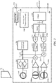
- FIG. 2 shows additional detail for an integrated circuit (IC) package implementation of the system of FIG. 1 .
- a main coil 200 is driven by a coil driver 202 coupled to a frequency generator 204, for example.
- coil driver 202 supplies current to the main coil 200 to generate a magnetic field.
- An alternating current may be used so that the main coil 200 produces alternating magnetic fields (i.e. magnetic fields with magnetic moments that change over time).
- the field generated by the main coil 200 causes a reflected signal to be generated by the target 10 that is received by first and second pick up coils 206a,b and amplified by amplifiers 208a,b.
- the first coil 206a is configured to generate a sine signal and the second coil 206b is configured to generate a cosine signal.
- the amplified pick up signals for the first and second coils 206a,b are demodulated 210 to bring the high frequency signal down to DC since the magnetic signal will be at the same frequency as that in the main coil, so one uses that same frequency to demodulate down to DC.
- the sine and cosine signals can be filtered 212, such as with low pass filters 210, and digitized by analog-to-digital converters (ADC) 214.
- ADC analog-to-digital converters
- the digitized sine and cosine signals 216a,b are provided to a signal processing module 218 to generate an angular position signal 220 that corresponds to the angular position ⁇ of the target 10.
- the arc tangent function e.g., tan ⁇ 1 sin ⁇ cos ⁇
- angular position processing is performed in the digital domain.
- angular position processing is performed in the analog domain.
- the angular position signal can be received by an output module 222.
- the output module can perform signal linearization, calibration, and the like, of the position signal prior to output from the IC, for example, on an output pin 224.
- the IC can include an IO pin 226 configured to receive a voltage supply signal VCC.
- a regulator module 228 can provide voltage signals throughout the IC and provide master bias and other functionality.
- the IC can further include memory 230 to store programming logic, provide volatile and/or non-volatile memory, and the like.
- the main coil 200 is energized with a signal having a frequency in the range of about 1 to about 10 MHz. It is understood that other frequencies can be used to meet the needs of a particular application.
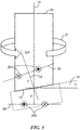
- FIG. 3 shows an example target 10 in the form of a cylinder having at an end 12 that is cut at an angle 14 shown as ⁇ .
- the angle 14 is defined in relation to a longitudinal axis 16 of the cylinder that is perpendicular to a plane/axis 18 in which the main coil 300 resides.
- the cut end 12 of the target is at least partially conductive.
- at least the end 12 of the target is formed from a conductive material, such as aluminum.
- a conductive material can be applied to the end 12 of the target, which may be formed from a conductive or non-conductive material.
- the cylinder 10 rotates about its longitudinal axis 16 with an angular position defined by ⁇ while the main coil 300 radiates a magnetic field toward the end 12 of the cylinder.
- a mirrored coil 20 is shown at a distance from the end 12 of the target at a given location. It is understood that the mirrored coil is an idealized model, which assumes a perfect conductor and vacuum, that can be used to model the reflected field from the conductive target end. It is understood that an X in a circle indicates a current into the paper and a dot in a circle indicates a current coming out of the paper.
- An example range for the cut angle is about +/-45 degrees. In many embodiments, the cut angle is between about 5 and 15 degrees.
- the end 12 of the target, at the axis 16 of the target, is located a distance d from the plane 18 of the main coil 300.
- the mirror coil 20 is located in a plane 30 that is bisected by a segment 32 extending perpendicularly from the mirror coil plane 30 such that an angle formed by segment 32 and the target longitudinal axis 16 is 2 ⁇ .
- the segment 32 extends a distance d from the end 12 of the target at the axis 16 to the plane 30 of the mirror coil 20.
- the main coil 300 causes a reflected field to emanate from the target 10.
- the reflected field can be modeled as the mirror coil 20.
- Pick up coils as described above and below, can receive the reflected field and generate an angular position signal for the target 10.
- the magnetic field from the main coil 300 induces Eddy currents in the conductive surface 12 of the target.
- an ideal conductor keeps AC magnetic flux lines from crossing its boundary which results in symmetry of the main and mirrored coil across the boundary of the conductor.
- FIG. 4 shows the combined field lines from a main coil and from a 'mirrored coil', which is located according to FIG 3 .
- the resulting fields never cross the target boundary 400.
- the main coil 300 applies a field on the target 10 that causes eddy currents to flow within the target.
- These eddy currents create their own magnetic fields that can be modeled as the mirror coil 20.
- currents will only flow on the surface of the target, but the effect will be as if the currents were flowing like mirror coil 20.
- Faraday's Law says that the voltage induced in a closed loop is proportional to the rate of change of the magnetic flux that the loop encloses. This means that an AC magnetic field crossing a sheet induces a voltage in the sheet.
- the cut angle provides an optimization. As one increases the cut angle, the angle of the reflected field increases, thereby increasing the differential seen by the pick-up coils, but one also has to increase distance d in order to keep the edge of the target from hitting the sensor, which reduces the field seen. In example embodiments, around 7.5 degrees provides the largest output signal for a 1 mm air-gap from the lowest point of the target to the sensor.
- FIG. 5 shows a rotating target 10 subjected to a field from the main coil 300 generating a reflected signal 500 shown below the target.
- the reflected signal from the mirror coil model is not symmetric.
- the asymmetric signal rotates about a rotation axis 502, which can correspond the target longitudinal axis 16, as the target 10 rotates. This asymmetric signal rotation can be detected by pickup coils.
- FIG. 5A shows the target rotated about 180 degrees and corresponding field.
- the current to the main coil 300 is 300 mA-turns. It is understood that only the mirrored coil is modelled in the illustrated embodiment. In embodiments, the main coil 300 field is substantially cancelled by differential pick up coils.
- the reflected field is plotted as B in the z-direction, which is what the pick up coils detect. As can be seen, the strongest field level is off center towards the closer piece of the cylinder 10. The reflected field rotates with the cylinder/target 10. With an offset reflected field, pick up coils centered on the main coil 300 will detect the off-center field.
- Coils can be circular, ovular, square, polygonal, and the like, and can have any practical width and thickness.
- the mutual inductance between the main and pickup coils changes as the target rotates.
- the mutual inductance is proportional to the sum of the fields directly produced by the main coil and reflected from the target, which the pick-up coils encompass. It is desirable to have low mutual inductance between the main coil and the pickup coils due to the direct field to enable sensing of the reflected field in the presence of the field generated by the main coil.
- Mutual inductance due to the direct field creates an offset that is constant over angle (theta), which can be large due to the close proximity of the coils, making it challenging to detect the small change in mutual inductance due to the reflected field changing over angle (theta).
- each of the pick-up coils encompass a total of near zero field from the main coil (note that encompassing field clockwise adds to the total and counterclockwise subtracts from the total), the mutual inductance due to the direct field will approach zero. That is, the pick-up coils are configured such that the net field from the main coil on the pick-up coils is substantially zero.
- first and second sets of differential pick up coils detect the field from the mirrored coil. Differential coils may cancel out the direct field from the main coil. In one embodiment, first and second sets of coils are 90 degrees out of phase to yield sine and cosine outputs on which an arctangent can be used. Using sine and cosine signals may enhance immunity to system variations, e.g., airgap, temperature, frequency etc., as well as stray field immunity. In addition, DC fields will not be picked up by the coils, while uniform AC fields may be rejected by the differential coils.
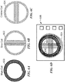
- FIG. 6A shows an example configuration for a main coil 600
- FIG. 6B shows an example configuration for a sine coil 602
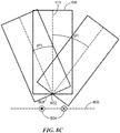
- FIG. 6C shows an example configuration for a cosine coil 604.
- FIG. 6D shows an example embodiment of a stacked arrangement 606 in which the main coil 600, cosine coil 604, and sine coil 602 overlap each other, wherein each coil has about the same radius.
- FIG. 7A shows a schematic representation 700 of the main coil 600 of FIG. 6A
- FIG. 7B shows a schematic representation 702 of the sine coil 602 of FIG. 6B
- FIG. 7C shows a schematic representation 704 of the cosine coil of 604 of FIG. 6C
- the sine coil 704 of FIG. 7C can be considered to have pick up coils 1 and 3
- the cosine coil 702 of FIG. 7B can be considered to have pick up coils 2 and 4.
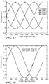
- FIG. 8A shows graphical representations of the signals for coil 1, coil 2, coil 3, and coil 4 versus target angle.
- FIG. 8B shows a graphical representation of a cosine output of (coil 4 - coil 2) and a since output of (coil 1 - coil 3) versus target angle.
- these signals are in quadrature, i.e., 90 degrees out of phase.
- Coils 1 and 3 (704 FIG. 7C ) are wound in opposite directions and connected in series.
- Coils 2 and 4 (702 FIG. 7B ) are wound in opposite directions and connected in series. It will be appreciated that the illustrated configuration results in substantially zero output from each coil set for common field, including the main coil. When the target rotates, one gets a sine output from one coil set and a cosine output from the other coil set. In general, the sine and cosine coils should be aligned accurately since asymmetry may cause offset errors.
- coils can be used to fabricate coils and other circuit features.
- additional metal layers can be added to standard processes.
- a relatively thick top layer can be used for the main coil and five or six metal layer processing can be used for the sine and cosine coils.
- pick-up coils may only cover about 90 degrees of area so as to reduce the number of layers required. Coils can be created on a PCB or separate IC for use with an interface IC to allow for larger coils that would work over a larger air gap, and thereby allow use of a smaller die.
- magnetic field sensing elements such as Hall elements and magnetoresistance (MR) elements
- Hall elements and magnetoresistance (MR) elements
- MR magnetoresistance
- a target 800 can pivot about a point 802 located above a main coil 804 and main coil plane 806. An end 808 of the target 800 rotates to define an angle phi with respect to a longitudinal axis 810 of the target.
- a sensor (not shown), such as the pick-up coils shown in in FIG. 6 , can detect the reflected field as the target 800 pivots to determine a slope of the target.
- the coils may be configured to reduce capacitive coupling between coils, e.g., main coil to pick-up coils and pick-up coil to pick-up coil, since such coupling may cause unwanted cross-talk between coils.
- FIG. 8D shows an example coil configuration 820 that adds shielding between coils.
- a main coil layer 822 is separated from a sine coil layer 824 with a grounded shield layer 826 between dielectric layers 828a,b.
- a cosine coil layer 830 is separated from the sine coil layer 824 by dielectric layer 828c.
- a grounded shield layer 832 is separated from the cosine coil layer 830 by dielectric layer 828d.
- the layers can be formed on a substrate 834, such as a silicon substrate. It is understood that alternative embodiments include layers in different orders with more or less dielectric layers and/or more or less shield layers.
- the coils are at least partially interdigitated for less coil overlap for reducing capacitance.
- FIG. 8E shows a stacked coil arrangement having some similarity to the arrangement shown in FIG. 6D . While the main, sine, and cosine coils overlap in FIG. 6D , in the embodiment of FIG. 8E , the main coil 840 is wound in a greater diameter to reduce or eliminate overlap with the sine coil 842 and cosine coil 844.
- FIG. 8F shows an embodiment of a coil 846 for reducing common mode voltage from inductive coupling by distributing the positive and negative mutual inductance from the main coil throughout the pick-up coil.
- a spiral design see, for example, the coil of FIG. 6B
- the net mutual inductance is only due to the reflections from the coil, but the average mutual inductance of the two halves may lead to a large common mode motion (not as large as the capacitive issue but still significant).
- the positive and negative mutual inductance in the FIG. 8F configuration common mode motion is created and destroyed in each turn of the coil to prevent build up. In this way, the common mode voltage is reduced from the spiral case, e.g., FIG. 6B , by around 1/N, where N is the number of turns in the coil.
- FIG. 8G shows an example embodiment of a main coil 850 with slots 852 formed in a conductive layer 844 (e.g., one of the shield layers in FIG. 8D ) to reduce eddy currents, which can degrade accuracy of the sensor. It is understood that any practical number of slots can be used in any suitable location to meet the needs of a particular location. FIG. 8G also shows how the conductive shield layer 844 exists between the coils and does not need to fill the entire region.
- FIG. 9 shows an example embodiment of an angular position sensor IC package 900 with a target 90 at a given air gap.
- the target 90 is shown as a cylinder having a cut end 92.
- the sensor 900 has a give die size that allows for a 1.5 mm diameter coil in the example embodiment.
- a 1.3 mm from die-face to target center results in the order of a 1 mm airgap from package face of the IC package 900 to lowest portion of the target 90, e.g., a 8 mm diameter rod.
- FIG. 10A shows an example target 1000 with a layer of conductive material 1002 on an end surface 1004 of the target.
- the target 1000 comprises a cylinder with 90 degree cuts at each end.
- the conductive material 1002 is applied to the end surface 1004 such that one side 1006 of the end surface has conductive material 1002 with a first thickness and the other side 1008 of the end surface 1004 has conductive material 1002 with a second thickness that is less than the first thickness.
- the varying thickness of the conductive material 1002 provides a conductivity gradient across the end surface 1004 of the target.
- the varying thickness of the conductive material 1002 may create a reflected field having some similarity with the target having a cut end, as described above.
- FIG. 10B shows an example target 1020 with a layer of conductive material 1022 on an end surface 1024 of the target 1020.
- the target 1020 comprises a cylinder with 90 cuts at each end.
- the conductive material 1022 is applied to the end surface 1024 with a substantially uniform thickness.
- the conductive material 1022 has properties that create a conductivity gradient across the end surface 1024 of the target.
- first and second materials are mixed in varying proportions to create the conductive material 1022 of uniform thickness and varying conductivity.
- the varying conductivity of the conductive material 1022 may create a reflected field having some similarity with the target having a cut end, as described above.
- FIG. 10C shows an example target 1040 with a layer of conductive material 1042 on a cut end surface 1024 of the target 1040.
- the conductive material 1022 is applied to the end surface 1024 with a thickness to form a parallel surface to a sensor.
- the term "magnetic field sensor” is used to describe a circuit that uses a magnetic field sensing element, generally in combination with other circuits.
- Magnetic field sensors are used in a variety of applications, including, but not limited to, an angle sensor that senses an angle of a direction of a magnetic field, a current sensor that senses a magnetic field generated by a current carried by a current-carrying conductor, a magnetic switch that senses the proximity of a ferromagnetic object, a rotation detector that senses passing ferromagnetic articles, for example, magnetic domains of a ring magnet or a ferromagnetic target (e.g., gear teeth) where the magnetic field sensor is used in combination with a back-biased or other magnet, and a magnetic field sensor that senses a magnetic field density of a magnetic field.
- an angle sensor that senses an angle of a direction of a magnetic field
- a current sensor that senses a magnetic field generated by a current carried by a current-carrying conductor
- a magnetic switch that senses the proximity of a ferromagnetic object
- a rotation detector that senses passing ferromagnetic articles,
- target and “magnetic target” are used to describe an object to be sensed or detected by a magnetic field sensor or magnetic field sensing element.
- the target may comprise a conductive material that allows for eddy currents to flow within the target, for example a metallic target that conducts electricity.
- FIG. 11 shows an exemplary computer 1100 that can perform at least part of the processing described herein.
- the computer 1100 includes a processor 1102, a volatile memory 1104, a non-volatile memory 1106 (e.g., hard disk), an output device 1107 and a graphical user interface (GUI) 1108 (e.g., a mouse, a keyboard, a display, for example).
- the non-volatile memory 1106 stores computer instructions 1112, an operating system 1116 and data 1118.
- the computer instructions 1112 are executed by the processor 1102 out of volatile memory 1104.
- an article 1120 comprises non-transitory computer-readable instructions.
- Processing may be implemented in hardware, software, or a combination of the two. Processing may be implemented in computer programs executed on programmable computers/machines that each includes a processor, a storage medium or other article of manufacture that is readable by the processor (including volatile and non-volatile memory and/or storage elements), at least one input device, and one or more output devices. Program code may be applied to data entered using an input device to perform processing and to generate output information.
- the system can perform processing, at least in part, via a computer program product, (e.g., in a machine-readable storage device), for execution by, or to control the operation of, data processing apparatus (e.g., a programmable processor, a computer, or multiple computers).
- a computer program product e.g., in a machine-readable storage device
- data processing apparatus e.g., a programmable processor, a computer, or multiple computers.
- Each such program may be implemented in a high level procedural or object-oriented programming language to communicate with a computer system.
- the programs may be implemented in assembly or machine language.
- the language may be a compiled or an interpreted language and it may be deployed in any form, including as a stand-alone program or as a module, component, subroutine, or other unit suitable for use in a computing environment.
- a computer program may be deployed to be executed on one computer or on multiple computers at one site or distributed across multiple sites and interconnected by a communication network.
- a computer program may be stored on a storage medium or device (e.g., CD-ROM, hard disk, or magnetic diskette) that is readable by a general or special purpose programmable computer for configuring and operating the computer when the storage medium or device is read by the computer.
- Processing may also be implemented as a machine-readable storage medium, configured with a computer program, where upon execution, instructions in the computer program cause the computer to operate.
- Processing may be performed by one or more programmable processors executing one or more computer programs to perform the functions of the system. All or part of the system may be implemented as, special purpose logic circuitry (e.g., an FPGA (field programmable gate array) and/or an ASIC (application-specific integrated circuit)).
- special purpose logic circuitry e.g., an FPGA (field programmable gate array) and/or an ASIC (application-specific integrated circuit)
Abstract
Description
- Magnetic field sensors are often used to detect a ferromagnetic target. For example, it is common to use high frequency magnetic field generation and detection to determine features of a conductive target. In particular, in NDT (Non-Destructive Testing) this is done to detect cracks or other defects in metals. Magnetic field sensors may act as sensors to detect motion or position of the target. Such sensors are ubiquitous in many areas of technology including robotics, automotive, manufacturing, etc. For example, a magnetic field sensor may be used to detect when a vehicle wheel locks up, triggering the vehicle control processor to engage the anti-lock braking system. In this example, the magnetic field sensor may detect rotation of the wheel. Magnetic field sensors may also detect distance to an object. For example, a magnetic field sensor may be used to detect the position of a hydraulic piston. Magnetic field sensors are also used to determine angular position information for a rotating target.
- The present invention provides method and apparatus for angle sensors having a main coil to generate magnetic fields that are reflected by a target with a conductive surface. The reflected field is generated by eddy currents in the conductive surface of the target. In embodiments, a target comprises a cylinder with an end cut at an angle. Magnetic field sensors, e.g., pick-up coils, can pick up the reflected field, which can be processed to determine an angular position of the target. In embodiments, quadrature pick up coils can be used to receive the reflected field and generate sine and cosine signals for processing.
- In embodiments, a main coil directs a magnetic field at a conductive target for inducing eddy currents in the target with one or more differential pick-up coils for detecting the reflected field from the target. In embodiments, the pick-up coil(s) are such that the average field from the main coil on a pick-up coil(s) is substantially zero. The average reflected field seen by the pick-up coil(s) is dependent on the angle of the surface of the conductive target in relation to the main and pick-up coil(s). A processing module is configured to process the reflected field seen by the pick-up coil(s) and determine the angular position of the target.
- In one aspect, a sensor comprises: a main coil to direct a magnetic field at a rotatable target for inducing eddy currents in the target; differential pick-up coils for detecting a reflected field from the target wherein each of the pick-up coils is configured such that an asymmetric reflected field from the target seen by the pick-up coils corresponds to conductive properties of a surface of the target in relation to the main coil and the pick-up coils; and a processing module to process the reflected magnetic field from the pick-up coils for determining an angular position of the target.
- A sensor can further include one or more of the following features: the target is configured to rotate about an axis of the target, the target comprises a cylinder and an end of the cylinder is cut at an angle corresponding to the asymmetric reflected field from the target, the angle corresponds to locations of eddy currents generated in the target by the main coil, the reflected field is generated by the induced eddy currents in the conductive surface, and wherein the reflected field is asymmetrical about an axis of the target, each of the pick-up coils is configured such that an average field from the main coil on the pick-up coils is substantially zero, a first one of the pick-up coils generates a sine signal corresponding to the angular position of the target and a second one of the pick-up coils includes a cosine signal corresponding to the angular position of the target, the processing module is configured for arc tangent processing of the sine and cosine signals to determine the angular position of the target, a strength of the reflected magnetic field corresponds to a distance between the end of the target and the main coil, an end of the target comprises a conductive material defining the conductive properties of the surface of the target, the conductive material varies in thickness to vary the conductivity of the end of the target, the pick-up coils comprise first and second matching coils that are ninety degrees out of phase with respect to each other, at least one ground plane is placed between the main and/or pick-up coils, the at least one ground plane includes at least one slot to reduce eddy current generation from the main coil, the main coil and pick-up coils are at least partially interdigitated, the sensor is formed on a single integrated circuit, one or more of the main coil and the pick-up coils is on a separate substrate, the pick-up coils comprise two half spirals, and/or the pick-up coils comprise concentric coils.
- In another aspect, a method comprises: employing a main coil to direct a magnetic field at a rotatable target for inducing eddy currents in the target; employing differential pick-up coils for detecting a reflected field from the target wherein each of the pick-up coils is configured such that an asymmetric reflected field from the target seen by the pick-up coils corresponds to conductive properties of a surface of the target in relation to the main coil and the pick-up coils; and processing the reflected magnetic field from the pick-up coils for determining an angular position of the target.
- A method can further include one or more of the following features: the target is configured to rotate about an axis of the target, the target comprises a cylinder and an end of the cylinder is cut at an angle corresponding to the asymmetric reflected field from the target, the angle corresponds to locations of eddy currents generated in the target by the main coil, the reflected field is generated by the induced eddy currents in the conductive surface, and wherein the reflected field is asymmetrical about an axis of the target, each of the pick-up coils is configured such that an average field from the main coil on the pick-up coils is substantially zero, a first one of the pick-up coils generates a sine signal corresponding to the angular position of the target and a second one of the pick-up coils includes a cosine signal corresponding to the angular position of the target, the processing module is configured for arc tangent processing of the sine and cosine signals to determine the angular position of the target, a strength of the reflected magnetic field corresponds to a distance between the end of the target and the main coil, an end of the target comprises a conductive material defining the conductive properties of the surface of the target, the conductive material varies in thickness to vary the conductivity of the end of the target, the pick-up coils comprise first and second matching coils that are ninety degrees out of phase with respect to each other, at least one ground plane is placed between the main and/or pick-up coils, the at least one ground plane includes at least one slot to reduce eddy current generation from the main coil, the main coil and pick-up coils are at least partially interdigitated, the sensor is formed on a single integrated circuit, one or more of the main coil and the pick-up coils is on a separate substrate, the pick-up coils comprise two half spirals, and/or the pick-up coils comprise concentric coils.
- In a further aspect, a sensor comprises: a main coil means for directing a magnetic field at a rotatable target for inducing eddy currents in the target; differential pick-up coil means for detecting a reflected field from the target wherein the differential pick-up coil means comprises pick up coils each configured such that an asymmetric reflected field from the target seen by the pick-up coils corresponds to conductive properties of a surface of the target in relation to the main coil means and the pick-up coils; and a processing means for processing the reflected magnetic field from the pick-up coils for determining an angular position of the target.
- The foregoing features of this invention, as well as the invention itself, may be more fully understood from the following description of the drawings in which:
-
FIG. 1 is a block diagram of an angular position sensor using eddy currents in accordance with example embodiments of the invention; -
FIG. 2 is a block diagram of an angular position sensor using eddy currents in accordance with example embodiments of the invention; -
FIG. 3 is a schematic representation of a target having a cut end that is conductive for which angular position can be sensed in accordance with example embodiments of the invention; -
FIG. 4 is a graphical representation of the magnetic fields created when eddy currents are generated in a cut end surface of the target ofFIG. 3 that can be used to determine an angle or rotation of the cut for the target in accordance with example embodiments of the invention; -
FIG. 5 is a schematic representation of a target and a field reflected by the target in accordance with example embodiments of the invention; -
FIG. 5A is a schematic representation of a target and a field reflected by the target that is rotated from its position inFIG. 5 in accordance with example embodiments of the invention; -
FIG. 6A is an example implementation of a main coil that can form at part of an angular position sensor using eddy currents in accordance with example embodiments of the invention; -
FIG. 6B is an example implementation of a first pick up coil that can form at part of an angular position sensor using eddy currents in accordance with example embodiments of the invention; -
FIG. 6C is an example implementation of a second coil that can form at part of an angular position sensor using eddy currents in accordance with example embodiments of the invention; -
FIG. 6D is a schematic representation of an example configuration for the main coil ofFIG. 6A , the first pick up coil ofFIG. 6B , and the second pick up coil ofFIG. 6C ; -
FIG. 7A is a schematic representation of a main coil that can form at part of an angular position sensor using eddy currents in accordance with example embodiments of the invention; -
FIG. 7B is a schematic representation of a first pick up coil that can form at part of an angular position sensor using eddy currents in accordance with example embodiments of the invention; -
FIG. 7C is schematic representation of a second coil that can form at part of an angular position sensor using eddy currents in accordance with example embodiments of the invention; -
FIG. 8A is a graphical representation of outputs of the coils ofFIGs. 7A-7C ; -
FIG. 8B is a graphical representation of since and cosine signals from the outputs of the coils ofFIGs. 7A-7C ; -
FIG. 8C shows a target that can pivot with respect to a main coil; -
FIG. 8D shows an example coil layer configuration; -
FIG. 8E shows an example coil stack up configuration; -
FIG. 8F shows an example coil arrangement; -
FIG. 8G shows an example coil arrangement with slots to reduce eddy currents; -
FIG. 9 is a schematic representation of angular position sensor IC package using eddy currents in accordance with example embodiments of the invention; -
FIG. 10A is a schematic representation of a target having an end surface with non-uniform layer of conductive material in accordance with example embodiments of the invention; -
FIG. 10B is a schematic representation of a target having an end surface with uniform layer of conductive material having a conductivity gradient in accordance with example embodiments of the invention; -
FIG. 10C is a schematic representation of a target having a cut end surface with a layer of conductive material that may form a surface that can be parallel to a sensor; and -
FIG. 11 is a schematic representation of an example computer that can perform at least a portion of the processing described herein. -
FIG. 1 shows an angle sensor system100 in accordance with example embodiments of the invention. Thetarget 10 is located in proximity to the angle sensor to enable determination of angular position. In one embodiment, thetarget 10 comprises a cylinder with an at least partially conductive end surface proximate theangle sensor 100, and more particularly, amain coil 102. Acoil driver module 104 energizes themain coil 102 with a signal that results in a signal reflected from thetarget 10. The reflected signal is received by a pick upcoil module 106 and demodulated by ademodulator module 108. In embodiments, the pick upcoil module 106 includes first and second coils arranged to enable sine and cosine signals to be generated and processed by asignal processing module 110. Thesignal processing module 110 can determine the angular position of thetarget 10 so that anoutput module 112 can output a signal corresponding to angular positon of thetarget 10. -
FIG. 2 shows additional detail for an integrated circuit (IC) package implementation of the system ofFIG. 1 . Amain coil 200 is driven by acoil driver 202 coupled to afrequency generator 204, for example. In embodiments,coil driver 202 supplies current to themain coil 200 to generate a magnetic field. An alternating current may be used so that themain coil 200 produces alternating magnetic fields (i.e. magnetic fields with magnetic moments that change over time). The field generated by themain coil 200 causes a reflected signal to be generated by thetarget 10 that is received by first and second pick upcoils 206a,b and amplified byamplifiers 208a,b. In embodiments, thefirst coil 206a is configured to generate a sine signal and thesecond coil 206b is configured to generate a cosine signal. The amplified pick up signals for the first andsecond coils 206a,b are demodulated 210 to bring the high frequency signal down to DC since the magnetic signal will be at the same frequency as that in the main coil, so one uses that same frequency to demodulate down to DC. The sine and cosine signals can be filtered 212, such as with low pass filters 210, and digitized by analog-to-digital converters (ADC) 214. - The digitized sine and
cosine signals 216a,b are provided to asignal processing module 218 to generate an angular position signal 220 that corresponds to the angular position θ of thetarget 10. In embodiments, the arc tangent function, e.g.,
output module 222. In embodiments, the output module can perform signal linearization, calibration, and the like, of the position signal prior to output from the IC, for example, on anoutput pin 224. - The IC can include an
IO pin 226 configured to receive a voltage supply signal VCC. Aregulator module 228 can provide voltage signals throughout the IC and provide master bias and other functionality. The IC can further includememory 230 to store programming logic, provide volatile and/or non-volatile memory, and the like. - In example embodiments, the
main coil 200 is energized with a signal having a frequency in the range of about 1 to about 10 MHz. It is understood that other frequencies can be used to meet the needs of a particular application. -
FIG. 3 shows anexample target 10 in the form of a cylinder having at anend 12 that is cut at anangle 14 shown as ϕ. In one embodiment, theangle 14 is defined in relation to alongitudinal axis 16 of the cylinder that is perpendicular to a plane/axis 18 in which themain coil 300 resides. Thecut end 12 of the target is at least partially conductive. In some embodiments, at least theend 12 of the target is formed from a conductive material, such as aluminum. In some embodiments, a conductive material can be applied to theend 12 of the target, which may be formed from a conductive or non-conductive material. Thecylinder 10 rotates about itslongitudinal axis 16 with an angular position defined by θ while themain coil 300 radiates a magnetic field toward theend 12 of the cylinder. A mirroredcoil 20 is shown at a distance from theend 12 of the target at a given location. It is understood that the mirrored coil is an idealized model, which assumes a perfect conductor and vacuum, that can be used to model the reflected field from the conductive target end. It is understood that an X in a circle indicates a current into the paper and a dot in a circle indicates a current coming out of the paper. An example range for the cut angle is about +/-45 degrees. In many embodiments, the cut angle is between about 5 and 15 degrees. - The
end 12 of the target, at theaxis 16 of the target, is located a distance d from theplane 18 of themain coil 300. Themirror coil 20 is located in aplane 30 that is bisected by asegment 32 extending perpendicularly from themirror coil plane 30 such that an angle formed bysegment 32 and the targetlongitudinal axis 16 is 2ϕ. Thesegment 32 extends a distance d from theend 12 of the target at theaxis 16 to theplane 30 of themirror coil 20. - As noted above, the
main coil 300 causes a reflected field to emanate from thetarget 10. The reflected field can be modeled as themirror coil 20. Pick up coils, as described above and below, can receive the reflected field and generate an angular position signal for thetarget 10. - In accordance with Maxwell's equations, the magnetic field from the
main coil 300 induces Eddy currents in theconductive surface 12 of the target. In addition, an ideal conductor keeps AC magnetic flux lines from crossing its boundary which results in symmetry of the main and mirrored coil across the boundary of the conductor. -
FIG. 4 shows the combined field lines from a main coil and from a 'mirrored coil', which is located according toFIG 3 . The resulting fields never cross thetarget boundary 400. In operation, themain coil 300 applies a field on thetarget 10 that causes eddy currents to flow within the target. These eddy currents create their own magnetic fields that can be modeled as themirror coil 20. In practice, currents will only flow on the surface of the target, but the effect will be as if the currents were flowing likemirror coil 20. It should be noted that Faraday's Law says that the voltage induced in a closed loop is proportional to the rate of change of the magnetic flux that the loop encloses. This means that an AC magnetic field crossing a sheet induces a voltage in the sheet. However, a perfect conductor cannot have a voltage induced on it, so, instead, currents develop on the surface to reject the magnetic field from going through the conductor. This is what one will see in a finite element simulation. However, one can model this behavior through symmetry. Basically, there is no field crossing the boundary by having symmetric coils (same size and current) across the boundary as shown inFIG. 3 . That is not where the actual currents flow, as there is no magnetic field inside the conductor, but rather models the magnetic fields external to the conductor as if those surface currents were flowing. That means that inFIG. 4 , the fields below the dashed line are the ones actually seen, and the ones above it will not exist in reality. - It will be appreciated that the cut angle provides an optimization. As one increases the cut angle, the angle of the reflected field increases, thereby increasing the differential seen by the pick-up coils, but one also has to increase distance d in order to keep the edge of the target from hitting the sensor, which reduces the field seen. In example embodiments, around 7.5 degrees provides the largest output signal for a 1 mm air-gap from the lowest point of the target to the sensor.
-
FIG. 5 shows arotating target 10 subjected to a field from themain coil 300 generating a reflectedsignal 500 shown below the target. As can be seen, in theplane 18 of themain coil 300 the reflected signal from the mirror coil model is not symmetric. The asymmetric signal rotates about arotation axis 502, which can correspond the targetlongitudinal axis 16, as thetarget 10 rotates. This asymmetric signal rotation can be detected by pickup coils.FIG. 5A shows the target rotated about 180 degrees and corresponding field. - The reflected
signal 500 is generated from an example modelled system in which d = 1 mm, θ = 5°, r = 1.5 mm (radius of main coil), where the main coil has outer radius of 1.5 mm and an inner radius of 1.05 mm. The current to themain coil 300 is 300 mA-turns. It is understood that only the mirrored coil is modelled in the illustrated embodiment. In embodiments, themain coil 300 field is substantially cancelled by differential pick up coils. - The reflected field is plotted as B in the z-direction, which is what the pick up coils detect. As can be seen, the strongest field level is off center towards the closer piece of the
cylinder 10. The reflected field rotates with the cylinder/target 10. With an offset reflected field, pick up coils centered on themain coil 300 will detect the off-center field. - It is understood that various types and arrangements of pick up coils can be used to meet the needs of a particular application. Coils can be circular, ovular, square, polygonal, and the like, and can have any practical width and thickness.
- It is understood that the mutual inductance between the main and pickup coils changes as the target rotates. The mutual inductance is proportional to the sum of the fields directly produced by the main coil and reflected from the target, which the pick-up coils encompass. It is desirable to have low mutual inductance between the main coil and the pickup coils due to the direct field to enable sensing of the reflected field in the presence of the field generated by the main coil. Mutual inductance due to the direct field creates an offset that is constant over angle (theta), which can be large due to the close proximity of the coils, making it challenging to detect the small change in mutual inductance due to the reflected field changing over angle (theta). Where each of the pick-up coils encompass a total of near zero field from the main coil (note that encompassing field clockwise adds to the total and counterclockwise subtracts from the total), the mutual inductance due to the direct field will approach zero. That is, the pick-up coils are configured such that the net field from the main coil on the pick-up coils is substantially zero.
- In embodiments, first and second sets of differential pick up coils detect the field from the mirrored coil. Differential coils may cancel out the direct field from the main coil. In one embodiment, first and second sets of coils are 90 degrees out of phase to yield sine and cosine outputs on which an arctangent can be used. Using sine and cosine signals may enhance immunity to system variations, e.g., airgap, temperature, frequency etc., as well as stray field immunity. In addition, DC fields will not be picked up by the coils, while uniform AC fields may be rejected by the differential coils.
-
FIG. 6A shows an example configuration for amain coil 600,FIG. 6B shows an example configuration for asine coil 602, andFIG. 6C shows an example configuration for acosine coil 604.FIG. 6D shows an example embodiment of astacked arrangement 606 in which themain coil 600,cosine coil 604, andsine coil 602 overlap each other, wherein each coil has about the same radius. -
FIG. 7A shows aschematic representation 700 of themain coil 600 ofFIG. 6A ,FIG. 7B shows a schematic representation 702 of thesine coil 602 ofFIG. 6B , andFIG. 7C shows aschematic representation 704 of the cosine coil of 604 ofFIG. 6C . As can be seen, thesine coil 704 ofFIG. 7C can be considered to have pick upcoils FIG. 7B can be considered to have pick upcoils -
FIG. 8A shows graphical representations of the signals forcoil 1,coil 2,coil 3, andcoil 4 versus target angle.FIG. 8B shows a graphical representation of a cosine output of (coil 4 - coil 2) and a since output of (coil 1 - coil 3) versus target angle. As can be seen, these signals are in quadrature, i.e., 90 degrees out of phase. Results shown are for a frequency of about 5 MHz, N = 10, where N is the number of turns for the coils. As can be seen, one gets about 5 mV pk-pk out of each coil set. - In the illustrated embodiment, four pick up coils are used, each encompassing about half the area of the main coil and are rotated 90 degrees from each other.
Coils 1 and 3 (704FIG. 7C ) are wound in opposite directions and connected in series.Coils 2 and 4 (702FIG. 7B ) are wound in opposite directions and connected in series. It will be appreciated that the illustrated configuration results in substantially zero output from each coil set for common field, including the main coil. When the target rotates, one gets a sine output from one coil set and a cosine output from the other coil set. In general, the sine and cosine coils should be aligned accurately since asymmetry may cause offset errors. - It is understood that a variety of techniques can be used to fabricate coils and other circuit features. In embodiments, additional metal layers can be added to standard processes. For example, in one particular embodiment, a relatively thick top layer can be used for the main coil and five or six metal layer processing can be used for the sine and cosine coils. In some embodiments, pick-up coils may only cover about 90 degrees of area so as to reduce the number of layers required. Coils can be created on a PCB or separate IC for use with an interface IC to allow for larger coils that would work over a larger air gap, and thereby allow use of a smaller die.
- In other embodiments, magnetic field sensing elements, such as Hall elements and magnetoresistance (MR) elements, can be used to pick up the reflected high frequency signals. It is understood that one can re-pin the MR structure to get a quadrature relationship.
- In an example embodiment shown in
FIG. 8C , atarget 800 can pivot about apoint 802 located above amain coil 804 andmain coil plane 806. Anend 808 of thetarget 800 rotates to define an angle phi with respect to alongitudinal axis 810 of the target. A sensor (not shown), such as the pick-up coils shown in inFIG. 6 , can detect the reflected field as thetarget 800 pivots to determine a slope of the target. - In some embodiments, the coils may be configured to reduce capacitive coupling between coils, e.g., main coil to pick-up coils and pick-up coil to pick-up coil, since such coupling may cause unwanted cross-talk between coils.
-
FIG. 8D shows anexample coil configuration 820 that adds shielding between coils. In the illustrated embodiment, amain coil layer 822 is separated from asine coil layer 824 with a groundedshield layer 826 betweendielectric layers 828a,b. Acosine coil layer 830 is separated from thesine coil layer 824 bydielectric layer 828c. A groundedshield layer 832 is separated from thecosine coil layer 830 bydielectric layer 828d. In embodiments, the layers can be formed on asubstrate 834, such as a silicon substrate. It is understood that alternative embodiments include layers in different orders with more or less dielectric layers and/or more or less shield layers. - In other embodiments, the coils are at least partially interdigitated for less coil overlap for reducing capacitance.
-
FIG. 8E shows a stacked coil arrangement having some similarity to the arrangement shown inFIG. 6D . While the main, sine, and cosine coils overlap inFIG. 6D , in the embodiment ofFIG. 8E , themain coil 840 is wound in a greater diameter to reduce or eliminate overlap with thesine coil 842 andcosine coil 844. -
FIG. 8F shows an embodiment of acoil 846 for reducing common mode voltage from inductive coupling by distributing the positive and negative mutual inductance from the main coil throughout the pick-up coil. In a spiral design (see, for example, the coil ofFIG. 6B ), there may be mutual inductance to the two halves of the pick-up coil from the main coil. The net mutual inductance is only due to the reflections from the coil, but the average mutual inductance of the two halves may lead to a large common mode motion (not as large as the capacitive issue but still significant). By distributing the positive and negative mutual inductance in theFIG. 8F configuration, common mode motion is created and destroyed in each turn of the coil to prevent build up. In this way, the common mode voltage is reduced from the spiral case, e.g.,FIG. 6B , by around 1/N, where N is the number of turns in the coil. -
FIG. 8G shows an example embodiment of amain coil 850 withslots 852 formed in a conductive layer 844 (e.g., one of the shield layers inFIG. 8D ) to reduce eddy currents, which can degrade accuracy of the sensor. It is understood that any practical number of slots can be used in any suitable location to meet the needs of a particular location.FIG. 8G also shows how theconductive shield layer 844 exists between the coils and does not need to fill the entire region. -
FIG. 9 shows an example embodiment of an angular positionsensor IC package 900 with atarget 90 at a given air gap. Thetarget 90 is shown as a cylinder having acut end 92. Thesensor 900 has a give die size that allows for a 1.5 mm diameter coil in the example embodiment. A 1.3 mm from die-face to target center results in the order of a 1 mm airgap from package face of theIC package 900 to lowest portion of thetarget 90, e.g., a 8 mm diameter rod. -
FIG. 10A shows anexample target 1000 with a layer ofconductive material 1002 on anend surface 1004 of the target. In one embodiment, thetarget 1000 comprises a cylinder with 90 degree cuts at each end. Theconductive material 1002 is applied to theend surface 1004 such that oneside 1006 of the end surface hasconductive material 1002 with a first thickness and theother side 1008 of theend surface 1004 hasconductive material 1002 with a second thickness that is less than the first thickness. The varying thickness of theconductive material 1002 provides a conductivity gradient across theend surface 1004 of the target. The varying thickness of theconductive material 1002 may create a reflected field having some similarity with the target having a cut end, as described above. -
FIG. 10B shows anexample target 1020 with a layer ofconductive material 1022 on anend surface 1024 of thetarget 1020. In one embodiment, thetarget 1020 comprises a cylinder with 90 cuts at each end. Theconductive material 1022 is applied to theend surface 1024 with a substantially uniform thickness. Theconductive material 1022 has properties that create a conductivity gradient across theend surface 1024 of the target. In an example embodiment, first and second materials are mixed in varying proportions to create theconductive material 1022 of uniform thickness and varying conductivity. The varying conductivity of theconductive material 1022 may create a reflected field having some similarity with the target having a cut end, as described above. -
FIG. 10C shows anexample target 1040 with a layer ofconductive material 1042 on acut end surface 1024 of thetarget 1040. Theconductive material 1022 is applied to theend surface 1024 with a thickness to form a parallel surface to a sensor. As used herein, the term "magnetic field sensor" is used to describe a circuit that uses a magnetic field sensing element, generally in combination with other circuits. Magnetic field sensors are used in a variety of applications, including, but not limited to, an angle sensor that senses an angle of a direction of a magnetic field, a current sensor that senses a magnetic field generated by a current carried by a current-carrying conductor, a magnetic switch that senses the proximity of a ferromagnetic object, a rotation detector that senses passing ferromagnetic articles, for example, magnetic domains of a ring magnet or a ferromagnetic target (e.g., gear teeth) where the magnetic field sensor is used in combination with a back-biased or other magnet, and a magnetic field sensor that senses a magnetic field density of a magnetic field. - As used herein, the terms "target" and "magnetic target" are used to describe an object to be sensed or detected by a magnetic field sensor or magnetic field sensing element. The target may comprise a conductive material that allows for eddy currents to flow within the target, for example a metallic target that conducts electricity.
-
FIG. 11 shows anexemplary computer 1100 that can perform at least part of the processing described herein. Thecomputer 1100 includes aprocessor 1102, avolatile memory 1104, a non-volatile memory 1106 (e.g., hard disk), anoutput device 1107 and a graphical user interface (GUI) 1108 (e.g., a mouse, a keyboard, a display, for example). Thenon-volatile memory 1106stores computer instructions 1112, anoperating system 1116 anddata 1118. In one example, thecomputer instructions 1112 are executed by theprocessor 1102 out ofvolatile memory 1104. In one embodiment, anarticle 1120 comprises non-transitory computer-readable instructions. - Processing may be implemented in hardware, software, or a combination of the two. Processing may be implemented in computer programs executed on programmable computers/machines that each includes a processor, a storage medium or other article of manufacture that is readable by the processor (including volatile and non-volatile memory and/or storage elements), at least one input device, and one or more output devices. Program code may be applied to data entered using an input device to perform processing and to generate output information.
- The system can perform processing, at least in part, via a computer program product, (e.g., in a machine-readable storage device), for execution by, or to control the operation of, data processing apparatus (e.g., a programmable processor, a computer, or multiple computers). Each such program may be implemented in a high level procedural or object-oriented programming language to communicate with a computer system. However, the programs may be implemented in assembly or machine language. The language may be a compiled or an interpreted language and it may be deployed in any form, including as a stand-alone program or as a module, component, subroutine, or other unit suitable for use in a computing environment. A computer program may be deployed to be executed on one computer or on multiple computers at one site or distributed across multiple sites and interconnected by a communication network. A computer program may be stored on a storage medium or device (e.g., CD-ROM, hard disk, or magnetic diskette) that is readable by a general or special purpose programmable computer for configuring and operating the computer when the storage medium or device is read by the computer. Processing may also be implemented as a machine-readable storage medium, configured with a computer program, where upon execution, instructions in the computer program cause the computer to operate.
- Processing may be performed by one or more programmable processors executing one or more computer programs to perform the functions of the system. All or part of the system may be implemented as, special purpose logic circuitry (e.g., an FPGA (field programmable gate array) and/or an ASIC (application-specific integrated circuit)).
- Having described exemplary embodiments of the invention, it will now become apparent to one of ordinary skill in the art that other embodiments incorporating their concepts may also be used. The embodiments contained herein should not be limited to disclosed embodiments but rather should be limited only by the spirit and scope of the appended claims. All publications and references cited herein are expressly incorporated herein by reference in their entirety.
- Elements of different embodiments described herein may be combined to form other embodiments not specifically set forth above. Various elements, which are described in the context of a single embodiment, may also be provided separately or in any suitable subcombination. Other embodiments not specifically described herein are also within the scope of the following claims.
Claims (23)
- A sensor, comprising:a main coil to direct a magnetic field at a rotatable target for inducing eddy currents in the target;differential pick-up coils for detecting a reflected field from the target wherein each of the pick up coils is configured such that an asymmetric reflected field from the target seen by the pick-up coils corresponds to conductive properties of a surface of the target in relation to the main coil and the pick-up coils; anda processing module to process the reflected magnetic field from the pick-up coils for determining an angular position of the target.
- The sensor according to claim 1, wherein the target comprises a cylinder and an end of the cylinder is cut at an angle corresponding to the asymmetric reflected field from the target.
- The sensor according to claim 1, wherein a first one of the pick-up coils generates a sine signal corresponding to the angular position of the target and a second one of the pick-up coils includes a cosine signal corresponding to the angular position of the target, and wherein the processing module is configured for arc tangent processing of the sine and cosine signals to determine the angular position of the target.
- The sensor according to claim 1, wherein an end of the target comprises a conductive material defining the conductive properties of the surface of the target, and wherein the conductive material varies in thickness to vary the conductivity of the end of the target.
- The sensor according to claim 1, wherein at least one ground plane is placed between the main and/or pick-up coils.
- The sensor according to claim 1, wherein the main coil and pick-up coils are at least partially interdigitated.
- The sensor according to claim 1, wherein the sensor is formed on a single integrated circuit.
- The sensor according to claim 1, wherein one or more of the main coil and the pick-up coils is on a separate substrate.
- A method, comprising:employing a main coil to direct a magnetic field at a rotatable target for inducing eddy currents in the target;employing differential pick-up coils for detecting a reflected field from the target wherein each of the pick-up coils is configured such that an asymmetric reflected field from the target seen by the pick-up coils corresponds to conductive properties of a surface of the target in relation to the main coil and the pick-up coils; andprocessing the reflected magnetic field from the pick-up coils for determining an angular position of the target.
- The method according to claim 9, or the sensor according to claim 1, wherein the target is configured to rotate about an axis of the target.
- The method according to claim 9, wherein the target comprises a cylinder and an end of the cylinder is cut at an angle corresponding to the asymmetric reflected field from the target.
- The method according to claim 11, or the sensor according to claim 2, wherein the angle corresponds to locations of eddy currents generated in the target by the main coil.
- The method according to claim 9, or the sensor according to claim 1, wherein the reflected field is generated by the induced eddy currents in the conductive surface, and wherein the reflected field is asymmetrical about an axis of the target.
- The method according to claim 9, or the sensor according to claim 1, wherein each of the pick-up coils is configured such that an average field from the main coil on the pick-up coils is substantially zero.
- The method according to claim 9, or the sensor according to claim 1, wherein a first one of the pick-up coils generates a sine signal corresponding to the angular position of the target and a second one of the pick-up coils includes a cosine signal corresponding to the angular position of the target.
- The method according to claim 9, or the sensor according to claim 1, wherein a strength of the reflected magnetic field corresponds to a distance between the end of the target and the main coil.
- The method according to claim 9, or the sensor according to claim 1, wherein an end of the target comprises a conductive material defining the conductive properties of the surface of the target.
- The method according to claim 9, or the sensor according to claim 1, wherein the pick-up coils comprise first and second matching coils that are ninety degrees out of phase with respect to each other.
- The method according to claim 9, wherein at least one ground plane is placed between the main and/or pick-up coils.
- The method according to claim 19, or the sensor according to claim 5, wherein the at least one ground plane includes at least one slot to reduce eddy current generation from the main coil.
- The method according to claim 9, or the sensor according to claim 1, wherein the pick-up coils comprise two half spirals.
- The method according to claim 9, or the sensor according to claim 1, wherein the pick-up coils comprise concentric coils.
- A sensor, comprising:a main coil means for directing a magnetic field at a rotatable target for inducing eddy currents in the target;differential pick-up coil means for detecting a reflected field from the target wherein the differential pick-up coil means comprises pick up coils each configured such that an asymmetric reflected field from the target seen by the pick-up coils corresponds to conductive properties of a surface of the target in relation to the main coil means and the pick-up coils; anda processing means for processing the reflected magnetic field from the pick-up coils for determining an angular position of the target.
Applications Claiming Priority (1)
| Application Number | Priority Date | Filing Date | Title |
|---|---|---|---|
| US201862634370P | 2018-02-23 | 2018-02-23 |
Publications (2)
| Publication Number | Publication Date |
|---|---|
| EP3531076A1 true EP3531076A1 (en) | 2019-08-28 |
| EP3531076B1 EP3531076B1 (en) | 2021-07-14 |
Family
ID=65529594
Family Applications (1)
| Application Number | Title | Priority Date | Filing Date |
|---|---|---|---|
| EP19158961.3A Active EP3531076B1 (en) | 2018-02-23 | 2019-02-22 | Angle sensor using eddy currents |
Country Status (2)
| Country | Link |
|---|---|
| US (1) | US11112230B2 (en) |
| EP (1) | EP3531076B1 (en) |
Families Citing this family (13)
| Publication number | Priority date | Publication date | Assignee | Title |
|---|---|---|---|---|
| US11150110B2 (en) | 2019-08-01 | 2021-10-19 | Allegro Microsystems, Llc | Sensor having a shaped coil |
| EP3783316B9 (en) * | 2019-08-22 | 2022-08-10 | Melexis Technologies SA | Magnetic sensor system |
| DE102019218399A1 (en) | 2019-11-27 | 2021-05-27 | Infineon Technologies Ag | INDUCTIVE ANGLE SENSOR WITH DISTANCE DETERMINATION |
| US11604058B2 (en) | 2020-02-25 | 2023-03-14 | Allegro Microsystems, Llc | Reducing stray magnetic field effect on an angle sensor |
| DE102020203275A1 (en) * | 2020-03-13 | 2021-09-16 | Robert Bosch Gesellschaft mit beschränkter Haftung | Inductive rotor position sensor device, drive device |
| DE102020207225A1 (en) * | 2020-06-09 | 2021-12-09 | Infineon Technologies Ag | INDUCTIVE ANGLE SENSOR WITH STRETCHED COILS |
| US11493361B2 (en) | 2021-02-26 | 2022-11-08 | Allegro Microsystems, Llc | Stray field immune coil-activated sensor |
| US11467235B1 (en) | 2021-05-28 | 2022-10-11 | Allegro Microsystems, Llc | Reducing stray magnetic field effects using a magnetic field feedback |
| US11578997B1 (en) | 2021-08-24 | 2023-02-14 | Allegro Microsystems, Llc | Angle sensor using eddy currents |
| US11630169B1 (en) | 2022-01-17 | 2023-04-18 | Allegro Microsystems, Llc | Fabricating a coil above and below a magnetoresistance element |
| US11782105B2 (en) | 2022-01-17 | 2023-10-10 | Allegro Microsystems, Llc | Fabricating planarized coil layer in contact with magnetoresistance element |
| CN115102581A (en) * | 2022-06-21 | 2022-09-23 | 维沃移动通信有限公司 | Electronic device |
| US20240110777A1 (en) | 2022-09-29 | 2024-04-04 | Allegro Microsystems, Llc | Sensor with estimated real-time parameter data |
Citations (4)
| Publication number | Priority date | Publication date | Assignee | Title |
|---|---|---|---|---|
| US6642711B2 (en) * | 2001-01-24 | 2003-11-04 | Texas Instruments Incorporated | Digital inductive position sensor |
| US20050225320A1 (en) * | 2004-04-09 | 2005-10-13 | Lee Joong K | Inductive position sensor |
| US20060104558A1 (en) * | 2002-07-02 | 2006-05-18 | Samuel Gallion | Instrumented antifriction bearing and electrical motor equipped therewith |
| US20070001666A1 (en) * | 2005-06-27 | 2007-01-04 | Lee Joong K | Linear and rotational inductive position sensor |
Family Cites Families (12)
| Publication number | Priority date | Publication date | Assignee | Title |
|---|---|---|---|---|
| JPH11304413A (en) * | 1998-04-20 | 1999-11-05 | Mitsubishi Electric Corp | Magnetism detecting device |
| US6639399B2 (en) * | 2001-02-06 | 2003-10-28 | Delphi Technologies, Inc. | Target wheel sensor assembly for determining position and direction of motion of a rotating target wheel |
| US7768083B2 (en) * | 2006-01-20 | 2010-08-03 | Allegro Microsystems, Inc. | Arrangements for an integrated sensor |
| US10495699B2 (en) | 2013-07-19 | 2019-12-03 | Allegro Microsystems, Llc | Methods and apparatus for magnetic sensor having an integrated coil or magnet to detect a non-ferromagnetic target |
| US10145908B2 (en) | 2013-07-19 | 2018-12-04 | Allegro Microsystems, Llc | Method and apparatus for magnetic sensor producing a changing magnetic field |
| US9267819B2 (en) * | 2014-06-12 | 2016-02-23 | Mitutoyo Corporation | Absolute position encoder scale having plates alternating with varying recesses |
| US10310028B2 (en) | 2017-05-26 | 2019-06-04 | Allegro Microsystems, Llc | Coil actuated pressure sensor |
| US10996289B2 (en) | 2017-05-26 | 2021-05-04 | Allegro Microsystems, Llc | Coil actuated position sensor with reflected magnetic field |
| US10324141B2 (en) | 2017-05-26 | 2019-06-18 | Allegro Microsystems, Llc | Packages for coil actuated position sensors |
| US10641842B2 (en) | 2017-05-26 | 2020-05-05 | Allegro Microsystems, Llc | Targets for coil actuated position sensors |
| US10837943B2 (en) | 2017-05-26 | 2020-11-17 | Allegro Microsystems, Llc | Magnetic field sensor with error calculation |
| US11428755B2 (en) | 2017-05-26 | 2022-08-30 | Allegro Microsystems, Llc | Coil actuated sensor with sensitivity detection |
-
2019
- 2019-02-22 EP EP19158961.3A patent/EP3531076B1/en active Active
- 2019-02-22 US US16/282,539 patent/US11112230B2/en active Active
Patent Citations (4)
| Publication number | Priority date | Publication date | Assignee | Title |
|---|---|---|---|---|
| US6642711B2 (en) * | 2001-01-24 | 2003-11-04 | Texas Instruments Incorporated | Digital inductive position sensor |
| US20060104558A1 (en) * | 2002-07-02 | 2006-05-18 | Samuel Gallion | Instrumented antifriction bearing and electrical motor equipped therewith |
| US20050225320A1 (en) * | 2004-04-09 | 2005-10-13 | Lee Joong K | Inductive position sensor |
| US20070001666A1 (en) * | 2005-06-27 | 2007-01-04 | Lee Joong K | Linear and rotational inductive position sensor |
Also Published As
| Publication number | Publication date |
|---|---|
| EP3531076B1 (en) | 2021-07-14 |
| US11112230B2 (en) | 2021-09-07 |
| US20190265018A1 (en) | 2019-08-29 |
Similar Documents
| Publication | Publication Date | Title |
|---|---|---|
| EP3531076B1 (en) | Angle sensor using eddy currents | |
| EP3608681B1 (en) | Magnetic field sensor | |
| CN108489379B (en) | Angle sensor with disturbance field suppression | |
| CN108020150B (en) | Multi-dimensional measurements using magnetic sensors and related systems, methods, and integrated circuits | |
| US9719771B2 (en) | Rotation angle sensor for absolute rotation angle determination even upon multiple revolutions | |
| EP3608682B1 (en) | Magnetic field sensor with spacer | |
| CN110133543B (en) | Magnetoresistive sensor system for stray field cancellation using auxiliary sensor signals | |
| US7956610B2 (en) | Sensor for sensing a magnetic field direction, magnetic field direction sensing, method for producing magnetic field sensors, and write-in apparatus for producing magnetic field sensors | |
| CN107389100A (en) | Off-axis magnetic field angular sensor | |
| CN101672902A (en) | Magnetic field sensor array for measuring spatial components of a magnetic field | |
| CN109917309A (en) | The reluctive transducer offset with stray magnetic field and and there is the system of sensors with auxiliary electrode | |
| CN109813212B (en) | Magnet device for angle detection | |
| EP3531074A2 (en) | Angular sensor system and method of stray field cancellation | |
| US11598654B2 (en) | High resolution angular inductive sensor and associated method of use | |
| US20180313670A1 (en) | Magnetism-detecting device and moving-body-detecting device | |
| Reddy et al. | Low cost planar coil structure for inductive sensors to measure absolute angular position | |
| CN107063310A (en) | The redundancy magnetic degree sensor of accuracy with raising | |
| CN115698641B (en) | Angular position sensor and associated method of use | |
| JP7230470B2 (en) | Magnetic detection device and moving body detection device | |
| CN109931863B (en) | Sickle-shaped magnet device for angle detection | |
| US11578997B1 (en) | Angle sensor using eddy currents | |
| JP2001336905A (en) | Magnetometric sensor | |
| US20230152125A1 (en) | Magnetic angle sensor with symmetrical geometric arrangement | |
| CN116635696A (en) | High resolution angle sensing sensor and associated methods of use | |
| WO2022132229A1 (en) | High resolution angular inductive sensor and associated method of use |
Legal Events
| Date | Code | Title | Description |
|---|---|---|---|
| PUAI | Public reference made under article 153(3) epc to a published international application that has entered the european phase |
Free format text: ORIGINAL CODE: 0009012 |
|
| STAA | Information on the status of an ep patent application or granted ep patent |
Free format text: STATUS: THE APPLICATION HAS BEEN PUBLISHED |
|
| AK | Designated contracting states |
Kind code of ref document: A1 Designated state(s): AL AT BE BG CH CY CZ DE DK EE ES FI FR GB GR HR HU IE IS IT LI LT LU LV MC MK MT NL NO PL PT RO RS SE SI SK SM TR |
|
| AX | Request for extension of the european patent |
Extension state: BA ME |
|
| STAA | Information on the status of an ep patent application or granted ep patent |
Free format text: STATUS: REQUEST FOR EXAMINATION WAS MADE |
|
| 17P | Request for examination filed |
Effective date: 20200224 |
|
| RBV | Designated contracting states (corrected) |
Designated state(s): AL AT BE BG CH CY CZ DE DK EE ES FI FR GB GR HR HU IE IS IT LI LT LU LV MC MK MT NL NO PL PT RO RS SE SI SK SM TR |
|
| GRAP | Despatch of communication of intention to grant a patent |
Free format text: ORIGINAL CODE: EPIDOSNIGR1 |
|
| STAA | Information on the status of an ep patent application or granted ep patent |
Free format text: STATUS: GRANT OF PATENT IS INTENDED |
|
| INTG | Intention to grant announced |
Effective date: 20210310 |
|
| GRAS | Grant fee paid |
Free format text: ORIGINAL CODE: EPIDOSNIGR3 |
|
| GRAA | (expected) grant |
Free format text: ORIGINAL CODE: 0009210 |
|
| STAA | Information on the status of an ep patent application or granted ep patent |
Free format text: STATUS: THE PATENT HAS BEEN GRANTED |
|
| AK | Designated contracting states |
Kind code of ref document: B1 Designated state(s): AL AT BE BG CH CY CZ DE DK EE ES FI FR GB GR HR HU IE IS IT LI LT LU LV MC MK MT NL NO PL PT RO RS SE SI SK SM TR |
|
| REG | Reference to a national code |
Ref country code: GB Ref legal event code: FG4D |
|
| REG | Reference to a national code |
Ref country code: DE Ref legal event code: R096 Ref document number: 602019006015 Country of ref document: DE |
|
| REG | Reference to a national code |
Ref country code: IE Ref legal event code: FG4D |
|
| REG | Reference to a national code |
Ref country code: AT Ref legal event code: REF Ref document number: 1411006 Country of ref document: AT Kind code of ref document: T Effective date: 20210815 |
|
| REG | Reference to a national code |
Ref country code: LT Ref legal event code: MG9D |
|
| REG | Reference to a national code |
Ref country code: NL Ref legal event code: MP Effective date: 20210714 |
|
| REG | Reference to a national code |
Ref country code: AT Ref legal event code: MK05 Ref document number: 1411006 Country of ref document: AT Kind code of ref document: T Effective date: 20210714 |
|
| PG25 | Lapsed in a contracting state [announced via postgrant information from national office to epo] |
Ref country code: HR Free format text: LAPSE BECAUSE OF FAILURE TO SUBMIT A TRANSLATION OF THE DESCRIPTION OR TO PAY THE FEE WITHIN THE PRESCRIBED TIME-LIMIT Effective date: 20210714 Ref country code: NO Free format text: LAPSE BECAUSE OF FAILURE TO SUBMIT A TRANSLATION OF THE DESCRIPTION OR TO PAY THE FEE WITHIN THE PRESCRIBED TIME-LIMIT Effective date: 20211014 Ref country code: PT Free format text: LAPSE BECAUSE OF FAILURE TO SUBMIT A TRANSLATION OF THE DESCRIPTION OR TO PAY THE FEE WITHIN THE PRESCRIBED TIME-LIMIT Effective date: 20211115 Ref country code: NL Free format text: LAPSE BECAUSE OF FAILURE TO SUBMIT A TRANSLATION OF THE DESCRIPTION OR TO PAY THE FEE WITHIN THE PRESCRIBED TIME-LIMIT Effective date: 20210714 Ref country code: LT Free format text: LAPSE BECAUSE OF FAILURE TO SUBMIT A TRANSLATION OF THE DESCRIPTION OR TO PAY THE FEE WITHIN THE PRESCRIBED TIME-LIMIT Effective date: 20210714 Ref country code: AT Free format text: LAPSE BECAUSE OF FAILURE TO SUBMIT A TRANSLATION OF THE DESCRIPTION OR TO PAY THE FEE WITHIN THE PRESCRIBED TIME-LIMIT Effective date: 20210714 Ref country code: BG Free format text: LAPSE BECAUSE OF FAILURE TO SUBMIT A TRANSLATION OF THE DESCRIPTION OR TO PAY THE FEE WITHIN THE PRESCRIBED TIME-LIMIT Effective date: 20211014 Ref country code: SE Free format text: LAPSE BECAUSE OF FAILURE TO SUBMIT A TRANSLATION OF THE DESCRIPTION OR TO PAY THE FEE WITHIN THE PRESCRIBED TIME-LIMIT Effective date: 20210714 Ref country code: RS Free format text: LAPSE BECAUSE OF FAILURE TO SUBMIT A TRANSLATION OF THE DESCRIPTION OR TO PAY THE FEE WITHIN THE PRESCRIBED TIME-LIMIT Effective date: 20210714 Ref country code: FI Free format text: LAPSE BECAUSE OF FAILURE TO SUBMIT A TRANSLATION OF THE DESCRIPTION OR TO PAY THE FEE WITHIN THE PRESCRIBED TIME-LIMIT Effective date: 20210714 Ref country code: ES Free format text: LAPSE BECAUSE OF FAILURE TO SUBMIT A TRANSLATION OF THE DESCRIPTION OR TO PAY THE FEE WITHIN THE PRESCRIBED TIME-LIMIT Effective date: 20210714 |
|
| PG25 | Lapsed in a contracting state [announced via postgrant information from national office to epo] |
Ref country code: PL Free format text: LAPSE BECAUSE OF FAILURE TO SUBMIT A TRANSLATION OF THE DESCRIPTION OR TO PAY THE FEE WITHIN THE PRESCRIBED TIME-LIMIT Effective date: 20210714 Ref country code: LV Free format text: LAPSE BECAUSE OF FAILURE TO SUBMIT A TRANSLATION OF THE DESCRIPTION OR TO PAY THE FEE WITHIN THE PRESCRIBED TIME-LIMIT Effective date: 20210714 Ref country code: GR Free format text: LAPSE BECAUSE OF FAILURE TO SUBMIT A TRANSLATION OF THE DESCRIPTION OR TO PAY THE FEE WITHIN THE PRESCRIBED TIME-LIMIT Effective date: 20211015 |
|
| REG | Reference to a national code |
Ref country code: DE Ref legal event code: R097 Ref document number: 602019006015 Country of ref document: DE |
|
| PG25 | Lapsed in a contracting state [announced via postgrant information from national office to epo] |
Ref country code: DK Free format text: LAPSE BECAUSE OF FAILURE TO SUBMIT A TRANSLATION OF THE DESCRIPTION OR TO PAY THE FEE WITHIN THE PRESCRIBED TIME-LIMIT Effective date: 20210714 |
|
| PLBE | No opposition filed within time limit |
Free format text: ORIGINAL CODE: 0009261 |
|
| STAA | Information on the status of an ep patent application or granted ep patent |
Free format text: STATUS: NO OPPOSITION FILED WITHIN TIME LIMIT |
|
| PG25 | Lapsed in a contracting state [announced via postgrant information from national office to epo] |
Ref country code: SM Free format text: LAPSE BECAUSE OF FAILURE TO SUBMIT A TRANSLATION OF THE DESCRIPTION OR TO PAY THE FEE WITHIN THE PRESCRIBED TIME-LIMIT Effective date: 20210714 Ref country code: SK Free format text: LAPSE BECAUSE OF FAILURE TO SUBMIT A TRANSLATION OF THE DESCRIPTION OR TO PAY THE FEE WITHIN THE PRESCRIBED TIME-LIMIT Effective date: 20210714 Ref country code: RO Free format text: LAPSE BECAUSE OF FAILURE TO SUBMIT A TRANSLATION OF THE DESCRIPTION OR TO PAY THE FEE WITHIN THE PRESCRIBED TIME-LIMIT Effective date: 20210714 Ref country code: EE Free format text: LAPSE BECAUSE OF FAILURE TO SUBMIT A TRANSLATION OF THE DESCRIPTION OR TO PAY THE FEE WITHIN THE PRESCRIBED TIME-LIMIT Effective date: 20210714 Ref country code: CZ Free format text: LAPSE BECAUSE OF FAILURE TO SUBMIT A TRANSLATION OF THE DESCRIPTION OR TO PAY THE FEE WITHIN THE PRESCRIBED TIME-LIMIT Effective date: 20210714 Ref country code: AL Free format text: LAPSE BECAUSE OF FAILURE TO SUBMIT A TRANSLATION OF THE DESCRIPTION OR TO PAY THE FEE WITHIN THE PRESCRIBED TIME-LIMIT Effective date: 20210714 |
|
| 26N | No opposition filed |
Effective date: 20220419 |
|
| PG25 | Lapsed in a contracting state [announced via postgrant information from national office to epo] |
Ref country code: IT Free format text: LAPSE BECAUSE OF FAILURE TO SUBMIT A TRANSLATION OF THE DESCRIPTION OR TO PAY THE FEE WITHIN THE PRESCRIBED TIME-LIMIT Effective date: 20210714 |
|
| PG25 | Lapsed in a contracting state [announced via postgrant information from national office to epo] |
Ref country code: MC Free format text: LAPSE BECAUSE OF FAILURE TO SUBMIT A TRANSLATION OF THE DESCRIPTION OR TO PAY THE FEE WITHIN THE PRESCRIBED TIME-LIMIT Effective date: 20210714 |
|
| REG | Reference to a national code |
Ref country code: CH Ref legal event code: PL |
|
| REG | Reference to a national code |
Ref country code: BE Ref legal event code: MM Effective date: 20220228 |
|
| PG25 | Lapsed in a contracting state [announced via postgrant information from national office to epo] |
Ref country code: LU Free format text: LAPSE BECAUSE OF NON-PAYMENT OF DUE FEES Effective date: 20220222 |
|
| PG25 | Lapsed in a contracting state [announced via postgrant information from national office to epo] |
Ref country code: FR Free format text: LAPSE BECAUSE OF NON-PAYMENT OF DUE FEES Effective date: 20220228 |
|
| PG25 | Lapsed in a contracting state [announced via postgrant information from national office to epo] |
Ref country code: LI Free format text: LAPSE BECAUSE OF NON-PAYMENT OF DUE FEES Effective date: 20220228 Ref country code: IE Free format text: LAPSE BECAUSE OF NON-PAYMENT OF DUE FEES Effective date: 20220222 Ref country code: CH Free format text: LAPSE BECAUSE OF NON-PAYMENT OF DUE FEES Effective date: 20220228 |
|
| PG25 | Lapsed in a contracting state [announced via postgrant information from national office to epo] |
Ref country code: BE Free format text: LAPSE BECAUSE OF NON-PAYMENT OF DUE FEES Effective date: 20220228 |
|
| PGFP | Annual fee paid to national office [announced via postgrant information from national office to epo] |
Ref country code: DE Payment date: 20221229 Year of fee payment: 5 |
|
| GBPC | Gb: european patent ceased through non-payment of renewal fee |
Effective date: 20230222 |
|
| PG25 | Lapsed in a contracting state [announced via postgrant information from national office to epo] |
Ref country code: GB Free format text: LAPSE BECAUSE OF NON-PAYMENT OF DUE FEES Effective date: 20230222 |
|
| PG25 | Lapsed in a contracting state [announced via postgrant information from national office to epo] |
Ref country code: GB Free format text: LAPSE BECAUSE OF NON-PAYMENT OF DUE FEES Effective date: 20230222 |