EP3531044A1 - Cooling flow control system - Google Patents
Cooling flow control system Download PDFInfo
- Publication number
- EP3531044A1 EP3531044A1 EP19153122.7A EP19153122A EP3531044A1 EP 3531044 A1 EP3531044 A1 EP 3531044A1 EP 19153122 A EP19153122 A EP 19153122A EP 3531044 A1 EP3531044 A1 EP 3531044A1
- Authority
- EP
- European Patent Office
- Prior art keywords
- load
- cooling
- valve
- recharge
- fluid
- Prior art date
- Legal status (The legal status is an assumption and is not a legal conclusion. Google has not performed a legal analysis and makes no representation as to the accuracy of the status listed.)
- Granted
Links
Images




Classifications
-
- F—MECHANICAL ENGINEERING; LIGHTING; HEATING; WEAPONS; BLASTING
- F25—REFRIGERATION OR COOLING; COMBINED HEATING AND REFRIGERATION SYSTEMS; HEAT PUMP SYSTEMS; MANUFACTURE OR STORAGE OF ICE; LIQUEFACTION SOLIDIFICATION OF GASES
- F25B—REFRIGERATION MACHINES, PLANTS OR SYSTEMS; COMBINED HEATING AND REFRIGERATION SYSTEMS; HEAT PUMP SYSTEMS
- F25B25/00—Machines, plants or systems, using a combination of modes of operation covered by two or more of the groups F25B1/00 - F25B23/00
- F25B25/005—Machines, plants or systems, using a combination of modes of operation covered by two or more of the groups F25B1/00 - F25B23/00 using primary and secondary systems
-
- F—MECHANICAL ENGINEERING; LIGHTING; HEATING; WEAPONS; BLASTING
- F01—MACHINES OR ENGINES IN GENERAL; ENGINE PLANTS IN GENERAL; STEAM ENGINES
- F01P—COOLING OF MACHINES OR ENGINES IN GENERAL; COOLING OF INTERNAL-COMBUSTION ENGINES
- F01P5/00—Pumping cooling-air or liquid coolants
- F01P5/02—Pumping cooling-air; Arrangements of cooling-air pumps, e.g. fans or blowers
-
- F—MECHANICAL ENGINEERING; LIGHTING; HEATING; WEAPONS; BLASTING
- F01—MACHINES OR ENGINES IN GENERAL; ENGINE PLANTS IN GENERAL; STEAM ENGINES
- F01P—COOLING OF MACHINES OR ENGINES IN GENERAL; COOLING OF INTERNAL-COMBUSTION ENGINES
- F01P7/00—Controlling of coolant flow
- F01P7/14—Controlling of coolant flow the coolant being liquid
-
- F—MECHANICAL ENGINEERING; LIGHTING; HEATING; WEAPONS; BLASTING
- F25—REFRIGERATION OR COOLING; COMBINED HEATING AND REFRIGERATION SYSTEMS; HEAT PUMP SYSTEMS; MANUFACTURE OR STORAGE OF ICE; LIQUEFACTION SOLIDIFICATION OF GASES
- F25D—REFRIGERATORS; COLD ROOMS; ICE-BOXES; COOLING OR FREEZING APPARATUS NOT OTHERWISE PROVIDED FOR
- F25D16/00—Devices using a combination of a cooling mode associated with refrigerating machinery with a cooling mode not associated with refrigerating machinery
-
- F—MECHANICAL ENGINEERING; LIGHTING; HEATING; WEAPONS; BLASTING
- F25—REFRIGERATION OR COOLING; COMBINED HEATING AND REFRIGERATION SYSTEMS; HEAT PUMP SYSTEMS; MANUFACTURE OR STORAGE OF ICE; LIQUEFACTION SOLIDIFICATION OF GASES
- F25D—REFRIGERATORS; COLD ROOMS; ICE-BOXES; COOLING OR FREEZING APPARATUS NOT OTHERWISE PROVIDED FOR
- F25D17/00—Arrangements for circulating cooling fluids; Arrangements for circulating gas, e.g. air, within refrigerated spaces
- F25D17/02—Arrangements for circulating cooling fluids; Arrangements for circulating gas, e.g. air, within refrigerated spaces for circulating liquids, e.g. brine
-
- F—MECHANICAL ENGINEERING; LIGHTING; HEATING; WEAPONS; BLASTING
- F24—HEATING; RANGES; VENTILATING
- F24F—AIR-CONDITIONING; AIR-HUMIDIFICATION; VENTILATION; USE OF AIR CURRENTS FOR SCREENING
- F24F5/00—Air-conditioning systems or apparatus not covered by F24F1/00 or F24F3/00, e.g. using solar heat or combined with household units such as an oven or water heater
- F24F5/0007—Air-conditioning systems or apparatus not covered by F24F1/00 or F24F3/00, e.g. using solar heat or combined with household units such as an oven or water heater cooling apparatus specially adapted for use in air-conditioning
- F24F5/0017—Air-conditioning systems or apparatus not covered by F24F1/00 or F24F3/00, e.g. using solar heat or combined with household units such as an oven or water heater cooling apparatus specially adapted for use in air-conditioning using cold storage bodies, e.g. ice
- F24F2005/0025—Air-conditioning systems or apparatus not covered by F24F1/00 or F24F3/00, e.g. using solar heat or combined with household units such as an oven or water heater cooling apparatus specially adapted for use in air-conditioning using cold storage bodies, e.g. ice using heat exchange fluid storage tanks
-
- F—MECHANICAL ENGINEERING; LIGHTING; HEATING; WEAPONS; BLASTING
- F25—REFRIGERATION OR COOLING; COMBINED HEATING AND REFRIGERATION SYSTEMS; HEAT PUMP SYSTEMS; MANUFACTURE OR STORAGE OF ICE; LIQUEFACTION SOLIDIFICATION OF GASES
- F25B—REFRIGERATION MACHINES, PLANTS OR SYSTEMS; COMBINED HEATING AND REFRIGERATION SYSTEMS; HEAT PUMP SYSTEMS
- F25B2400/00—Component parts or details not otherwise provided for in this subclass
- F25B2400/24—Thermal storage element
-
- F—MECHANICAL ENGINEERING; LIGHTING; HEATING; WEAPONS; BLASTING
- F28—HEAT EXCHANGE IN GENERAL
- F28D—HEAT-EXCHANGE APPARATUS, NOT PROVIDED FOR IN ANOTHER SUBCLASS, IN WHICH THE HEAT-EXCHANGE MEDIA DO NOT COME INTO DIRECT CONTACT
- F28D20/00—Heat storage plants or apparatus in general; Regenerative heat-exchange apparatus not covered by groups F28D17/00 or F28D19/00
- F28D20/02—Heat storage plants or apparatus in general; Regenerative heat-exchange apparatus not covered by groups F28D17/00 or F28D19/00 using latent heat
-
- H—ELECTRICITY
- H05—ELECTRIC TECHNIQUES NOT OTHERWISE PROVIDED FOR
- H05K—PRINTED CIRCUITS; CASINGS OR CONSTRUCTIONAL DETAILS OF ELECTRIC APPARATUS; MANUFACTURE OF ASSEMBLAGES OF ELECTRICAL COMPONENTS
- H05K7/00—Constructional details common to different types of electric apparatus
- H05K7/20—Modifications to facilitate cooling, ventilating, or heating
-
- Y—GENERAL TAGGING OF NEW TECHNOLOGICAL DEVELOPMENTS; GENERAL TAGGING OF CROSS-SECTIONAL TECHNOLOGIES SPANNING OVER SEVERAL SECTIONS OF THE IPC; TECHNICAL SUBJECTS COVERED BY FORMER USPC CROSS-REFERENCE ART COLLECTIONS [XRACs] AND DIGESTS
- Y02—TECHNOLOGIES OR APPLICATIONS FOR MITIGATION OR ADAPTATION AGAINST CLIMATE CHANGE
- Y02E—REDUCTION OF GREENHOUSE GAS [GHG] EMISSIONS, RELATED TO ENERGY GENERATION, TRANSMISSION OR DISTRIBUTION
- Y02E60/00—Enabling technologies; Technologies with a potential or indirect contribution to GHG emissions mitigation
- Y02E60/14—Thermal energy storage
Definitions
- This disclosure relates to thermal management and, in particular, to thermal management of steady-state and transient thermal loads.
- the system further comprises a first junction and a second junction, wherein the first junction is configured to split cooling fluid received from the cooling pump between the cooling source and the low-load valve, wherein the second junction is configured to split cooling fluid received form the cooling source between the high-load valve and the thermal energy storage.
- the method further comprises the steps of: switching to a recharge mode in response to a recharge enable trigger, wherein switching to the recharge mode comprises: enabling a recharge fluid flow by opening a recharge valve, the recharge fluid flow comprising cooling fluid from an output of the thermal energy storage that flows to the cooling pump, and cooling the thermal load with cooling fluid that is a mixture of the first fluid flow received from the thermal energy storage and a bypass fluid flow comprising cooling fluid that is heated by the thermal load and pumped through a recharge pump.
- system further comprises a controller, wherein the controller is further configured to: in response to detection of a high-load trigger, cause the low-load valve to close and the high-load valve to open.
- system further comprises a controller, wherein the controller is further configured to: in response to detection of a low-load trigger, cause the low-load valve to open and the high-load valve to close.
- the output of the mixing valve may be in fluid communication with a thermal load.
- the first input of the mixing valve may be in fluid communication with the thermal energy storage.
- the second input of the mixing valve may be in fluid communication with the recharge pump.
- the thermal energy storage may receive cooling fluid heated by the thermal load and pumped through the cooling source by the cooling pump.
- an interesting feature of the systems and methods described below may be that coordinated operation of the low-load valve and the high-load valve may vary a source of cooling fluid used in a mixture of cooling fluid that cools the thermal load. Varying the source of cooling fluid used in mixture may preserve a cooling potential of the thermal energy storage and/or enable the use of smaller cooling components.
- the system 100 may recharge the thermal energy storage 106.
- Recharging the thermal energy storage 106 may refer to providing chilled cooling fluid to the thermal energy storage 106 such that a cooling potential of the thermal energy storage 106 increases.
- recharging the thermal energy storage 106 may involve decreasing a temperature of the thermal energy storage 106, or cooling fluid residing in the thermal energy storage 106.
- the rapid recharging of the thermal energy storage 106 may occur between periods of peak thermal demand.
- the system 100 may include a check valve 129.
- the check valve 129 may receive cooling fluid pumped by the recharge pump 124.
- the mixing valve 108 may receive the bypass fluid flow 128 from the check valve 129.
- the check valve 129 may prevent cooling fluid from output from the cooling pump 102 from flowing toward an output of the recharge pump 124.
- the check valve 129 may prevent the cooling pump 102 from drawing cooling fluid from the output of the cooling pump 102.
- the check valve 129 may prevent the cooling pump 102 from drawing cooling fluid directly from the output of the cooling pump 102.
- the mixing valve 108 may include a valve that blends cooling fluid from two or more sources.
- the mixing valve 108 may include multiple inputs, such as the first input 110, the second input 112, and/or any number of additional inputs.
- the mixing valve 108 may provide the output that comprises a mixture of cooling fluid received from one or more of the inputs.
- the mixing valve 108 may bias one or more of the inputs.
- the mixing valve 108 may receive more cooling fluid from the first input 110 and less cooling fluid from the second input 112.
- the mixing valve 108 may bias one or more of the inputs to achieve the target cooling temperature.
- the second input 112 of the mixing valve may receive cooling fluid that is warmer than cooling fluid received by the first input 110.
- the mixing valve may bias the second input 112 to increase a temperature of the output fluid flow 119.
- the mixing valve may bias the first input 110 to decrease the temperature of the output fluid flow 119.
- the thermal load 114 may include a device that receives cooling.
- the thermal load 114 may generate heat in transient and/or steady-state operation.
- the thermal load 114 may operate in various states. When operating in each state, the thermal load 114 may produce different amounts of heat, which may increase or decrease over time.
- the thermal load 114 may operate efficiently and/or properly within a temperature band or close to a predetermined target cooling temperature.
- the mixing valve 108 may cool the thermal load 114 within the temperature band or to the target cooling temperature.
- the system 100 may be implemented in various ways. As illustrated in FIGS 2A-C , the system 100 may include the recharge valve 122, the recharge pump 124, the low-load valve 202, and the high-load valve 204. In other examples, the system 100 may include the load-load valve and the high-load valve 204 without the recharge pump 124 and recharge valve 122. In other examples, the system 100 may include the recharge valve 122 and the recharge pump 124 without the low-load valve 202 and/or the high-load valve 204.
- the junctions 206A-F may include a second junction 206B.
- the second junction 206B may be in fluid communication with the thermal load 114, the cooling pump 102, and/or the recharge valve 122.
- the second junction 206B may be in fluid communication with the first junction 206A.
- the second junction 206B may be downstream from the thermal load 114, the recharge valve 122, and/or the first junction 206A.
- heated cooling fluid may flow from the thermal load 114, through the first junction 206A and to the second junction 206B.
- the second junction 206B may receive the heated cooling fluid from the thermal load 114.
- the controller 132 may cause the system 100 to switch to a recharge mode.
- the controller 132 may enable the recharge fluid flow 126 from the thermal energy storage 106 to the cooling pump 102 (308).
- the controller 132 may open the recharge valve 122 to enable the recharge fluid flow 126. Opening the recharge valve 122 may cause the cooling pump 102 to draw cooling fluid from the thermal energy storage 106 and recirculate the cooling fluid to the cooling source 104.
- the controller 132 may cause the thermal load 114 to be cooled with cooling fluid that is a mixture of the first fluid flow 116 received from the thermal energy storage 106 and the fourth fluid flow received from the cooling source 104 (514). For example, in response to detection of the high-load trigger, the controller 132 may open the high-load valve 204 and close the low-load valve 202. Closing the low-load valve 202 may stop the second fluid flow 118 to the second input 112 of the mixing valve 108. Opening the high-load valve 204 may enable the fourth fluid flow. For example, opening the high-load valve 204 may cause cooling fluid heated by the thermal load 114 and cooled by the cooling source 104 to flow to both the second input 112 of the mixing valve 108 and to the thermal energy storage 106. The mixing valve 108 may receive the first fluid flow 116 and the fourth fluid flow. The first fluid flow 116 may include cooling fluid from the thermal energy storage 106. The fourth fluid flow may include cooling fluid that bypasses the thermal energy storage 106.
- the recharge enable trigger may include a signal sent to the controller 132.
- Detection of the recharge enable trigger may include receipt of the signal.
- the controller 132 may receive the signal from the thermal load 114, a device in communication with the thermal load 114, or some other device.
- the signal may indicate the recharge enable trigger.
- the signal may include a parameter used to detect the recharge enable trigger.
- the controller 132 may disable the second fluid flow 118 and/or the fourth fluid flow (518). For example, the controller 132 may close the low-load valve 202 or cause the low-load valve 202 to stay closed. Alternatively or in addition, the controller 132 may close the high-load valve 204 or cause the high-load valve 204 to remain closed. In other examples, the controller 132 may send a signal, or cease sending a signal, to cause the low-load valve 202 and/or the high-load valve 204 to close or remain closed.
- the memory may include the logic switch between the cooling modes, such as the recharge mode, the low-load mode, and/or the high-load mode described herein.
- the memory may include logic that causes the components of the system to operate for their intended purpose.
- the memory may include logic that controls the cooling pump 102, the cooling source 104, the mixing valve 108, the recharge valve 122, the recharge pump 124, low-load valve 202 and/or the high-load valve 204.
Landscapes
- Engineering & Computer Science (AREA)
- Mechanical Engineering (AREA)
- General Engineering & Computer Science (AREA)
- Chemical & Material Sciences (AREA)
- Combustion & Propulsion (AREA)
- Physics & Mathematics (AREA)
- Thermal Sciences (AREA)
- Cooling Or The Like Of Electrical Apparatus (AREA)
- Other Air-Conditioning Systems (AREA)
- Fuel Cell (AREA)
- Devices That Are Associated With Refrigeration Equipment (AREA)
Abstract
Description
- This disclosure relates to thermal management and, in particular, to thermal management of steady-state and transient thermal loads.
- Cooling systems may be designed to handle peak constant thermal loads without regard to whether loads may be transient or without regard to the physical size of components in the thermal management system. The components of such cooling systems may be oversized or inefficiently controlled and yet still meet design goals. Present approaches to thermal management may suffer from a variety of drawbacks, limitations, and disadvantages. There is a need for inventive systems, methods, components, and apparatuses described herein.
- According to a first aspect of the disclosure there is provided a system comprising:
a cooling pump; a cooling source; a thermal energy storage; a mixing valve having a first input and a second input; a low-load valve; a high-load valve; and a controller, wherein the cooling pump is in fluid communication with a thermal load, the low-load valve, and the cooling source, wherein the cooling source is in fluid communication with the high-load valve and the thermal energy storage, wherein the first input of the mixing valve is in fluid communication with the thermal energy storage, wherein the second input of the mixing valve is in fluid communication with the low-load valve and the high-load valve, wherein the controller is configured to: in response to detection of a low-load trigger, cause the low-load valve to open and the high-load valve to close, and in response to detection of a high-load trigger, cause the low-load valve to close and the high-load valve to open. - Optionally, detection of the high-load trigger comprises determination that a temperature of cooling fluid provided by the cooling source exceeds a threshold temperature value.
Optionally, the cooling source and the low-load valve are downstream from the cooling pump, wherein the high-load valve and thermal energy storage are downstream from the cooling source, wherein the first input of the mixing valve is downstream from the thermal energy storage and the second input of the mixing valve is downstream from the low-load valve and the high-load valve. - Optionally, the system further comprises a first junction and a second junction, wherein the first junction is configured to split cooling fluid received from the cooling pump between the cooling source and the low-load valve, wherein the second junction is configured to split cooling fluid received form the cooling source between the high-load valve and the thermal energy storage.
- Optionally, the controller is further configured to: in response to at least one of the low-load trigger or the high-load trigger: cause the recharge valve to close, and cause the recharge pump to stop pumping.
- According to a second aspect of the disclosure there is provided a method comprising the steps of: cooling a thermal load with cooling fluid that is a mixture of a first fluid flow received from a thermal energy storage and a second fluid flow comprising cooling fluid heated by a thermal load and pumped through a cooling pump, the second fluid flow controlled by a low-load valve; supplying a thermal energy storage with a third fluid flow comprising cooling fluid cooled by a cooling source; switching to a high-load mode in response to a high-load trigger, wherein switching to the high-load mode comprises: disabling the second fluid flow by closing the low-load valve; enabling a fourth fluid flow by opening a high-load valve, the fourth fluid flow comprising cooling fluid cooled by the cooling source, where the fourth fluid flow is caused by the cooling pump; and cooling the thermal load with cooling fluid that is a mixture of the first fluid flow received from the thermal energy storage and the fourth fluid flow received from the cooling source.
- Optionally the method further comprises the steps of: switching to a low-load mode in response to a low-load trigger, wherein switching to the low-load mode comprises: enabling the second fluid flow by opening the low-load valve, disabling the fourth fluid flow by closing the high-load valve, and cooling the thermal load with the cooling fluid that is the mixture of the first fluid flow and the second fluid flow.
- Optionally the method further comprises the steps of: switching to a recharge mode in response to a recharge enable trigger, wherein switching to the recharge mode comprises: enabling a recharge fluid flow by opening a recharge valve, the recharge fluid flow comprising cooling fluid from an output of the thermal energy storage that flows to the cooling pump, and cooling the thermal load with cooling fluid that is a mixture of the first fluid flow received from the thermal energy storage and a bypass fluid flow comprising cooling fluid that is heated by the thermal load and pumped through a recharge pump.
- Optionally the step of switching to the recharge mode further comprises: disabling the fourth fluid flow by closing the high-load valve, or disabling the fourth fluid flow by closing the low-load valve.
- Optionally the method further comprises the step of: detecting the high-load trigger by determining that a temperature of cooling fluid cooled by the cooling source is greater than a threshold value.
- Optionally the method further comprises the step of: causing a mixing valve to adjust between a first input and a second input, wherein the first input receives the first fluid flow and the second input receives the second fluid flow or the fourth fluid flow.
- Optionally the method further comprises the steps of: pumping, with the cooling pump, the first fluid flow to a first input of a mixing valve; and pumping, with the cooling pump, the second fluid flow a second input of the mixing valve, wherein switching to the high-load mode further comprises pumping, with the cooling pump, the fourth fluid flow to the second input of the mixing valve.
- According to a third aspect of the disclosure there is provided a system comprising: a cooling pump; a cooling source; a thermal energy storage; a low-load valve; a high-load valve; and a mixing valve having a first input, a second input, and an output; wherein the cooling source and the low-load valve are downstream from the cooling pump, wherein the high-load valve and thermal energy storage are downstream from the cooling source, wherein the first input of the mixing valve is downstream from the thermal energy storage and the second input of the mixing valve is downstream from the low-load valve and the high-load valve, wherein the thermal load is downstream from the output of the mixing valve, wherein cooling fluid from the thermal load and pumped by the cooling pump flows to the second input of the mixing valve in response to the low-load valve being open and the high-load valve being closed, wherein cooling fluid from the thermal load and cooled by the cooling source flows to the second input of the mixing valve in response to the low-load valve being closed and the high-load valve being opened.
- Optionally the system further comprises a controller, wherein the controller is further configured to: in response to detection of a high-load trigger, cause the low-load valve to close and the high-load valve to open.
- Optionally, the controller is further configured to: communicate a signal to the mixing valve that causes the mixing valve to bias the first input of the mixing valve or the second input of the mixing valve.
- Optionally the system further comprises a controller, wherein the controller is further configured to: in response to detection of a low-load trigger, cause the low-load valve to open and the high-load valve to close.
- Optionally the system further comprises a first junction and a second junction, the first junction downstream from the cooling pump and the second junction downstream from the cooling source, wherein the first junction splits cooling fluid received from the cooling pump between the low-load valve and the cooling source, wherein the second junction splits cooling fluid received from the cooling source between the high-load valve and the thermal energy storage.
- Optionally, the cooling pump is in fluid communication with the low-load valve and the cooling source, the cooling source is in fluid communication with the high-load valve and the thermal energy storage, wherein the first input of the mixing valve receives cooling fluid from the thermal energy storage and the second input of the mixing valve receives cooling fluid from at least one of the low-load valve or the high-load valve.
- Optionally, the second input of the mixing valve receives cooling fluid from the cooling pump in response to the low-load valve being opened and the second input of the mixing valve receives cooling fluid from the cooling source in response to the high-load valve being opened.
- Optionally, the system further comprises a recharge pump and a recharge valve, the recharge pump in fluid communication with the thermal load and the second input of the mixing valve and the recharge valve in fluid communication with the thermal energy storage and the cooling pump, wherein the controller is further configured to: in response to a recharge enable trigger: cause the recharge valve to open, cause at least one of the low-load valve or the high-load valve to close, and cause the recharge pump to pump cooling fluid from the thermal load to the second input of the mixing valve.
- The embodiments may be better understood with reference to the following drawings and description. The components in the figures are not necessarily to scale. Moreover, in the figures, like-referenced numerals designate corresponding parts throughout the different views.
-
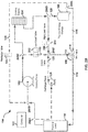
FIG. 1 illustrates a first example of a system; -
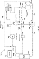
FIG. 2A-C illustrates a second example of a system; -
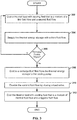
FIG. 3 illustrates a first example of a flow diagram for logic of a system; -
FIG. 4 illustrates a second example of a flow diagram for logic of a system; and -
FIG. 5 illustrates a third example of a flow diagram for logic of a system. - By way of an introductory example, the system may include a cooling pump, a cooling source, a thermal energy storage, a mixing valve having a first input, a second input, and an output, a recharge valve, a recharge pump, and/or a controller.
- The output of the mixing valve may be in fluid communication with a thermal load. The first input of the mixing valve may be in fluid communication with the thermal energy storage. The second input of the mixing valve may be in fluid communication with the recharge pump. The thermal energy storage may receive cooling fluid heated by the thermal load and pumped through the cooling source by the cooling pump.
- Operation of the recharge pump may cause heated cooling fluid output from the thermal load to bypass the cooling pump and flow to the second input of the mixing valve. The recharge valve may be in fluid communication with the thermal energy storage and the cooling pump. The recharge valve may regulate a recharge fluid flow comprising cooling fluid received from the thermal energy storage.
- In response to detection of a recharge enable trigger, the controller may open to the recharge valve to enable the recharge fluid flow and cause the operation of the recharge pump. In response to detection of a recharge disable trigger, the controller may close the recharge valve to disable the recharge fluid flow and stop the operation of the recharge pump.
- In some examples, the system may include a low-load valve and/or a high-load valve. The cooling source and the low-load valve may be downstream from the cooling pump. The high-load valve and thermal energy storage may be downstream from the cooling source. The first input of the mixing valve may be downstream from the thermal energy storage and the second input of the mixing valve is downstream from the low-load valve and the high-load valve. The thermal load may be downstream from the output of the mixing valve.
- Cooling fluid from the thermal load that is pumped by the cooling pump may flow to the second input of the mixing valve in response to the low-load valve being open and the high-load valve being closed.
- Cooling fluid from the thermal load and cooled by the cooling source may flow to the second input of the mixing valve in response to the low-load valve being closed and the high-load valve being opened.
- One interesting feature of the systems and methods described below may be that cooling fluid flowing within a cooling circuit may be controlled with one or more valves and/or pumps to reduce size, capacity, and power consumption of cooling components. For example, the recharge pump may provide the mixing valve with heated cooling fluid while the cooling pump recirculates cooling fluid from the thermal energy storage. The system and methods described below may provide rapid re-chilling of the thermal energy storage for a thermal load that operates within a temperature range. Alternatively or in addition, the system and methods described below may enable use of smaller cooling components while maintaining cooling availability for thermal loads with transient cooling demands.
- Alternatively, or in addition, an interesting feature of the systems and methods described below may be that coordinated operation of the low-load valve and the high-load valve may vary a source of cooling fluid used in a mixture of cooling fluid that cools the thermal load. Varying the source of cooling fluid used in mixture may preserve a cooling potential of the thermal energy storage and/or enable the use of smaller cooling components.
-
FIG. 1 illustrates a first example of asystem 100. Thesystem 100 may include acooling pump 102, acooling source 104, athermal energy storage 106, and/or amixing valve 108. The mixingvalve 108 may include afirst input 110, asecond input 112, and anoutput 113. Thecooling pump 102 may be in fluid communication with thecooling source 104, thesecond input 112 of the mixingvalve 108, and athermal load 114. Thethermal energy storage 106 may be in fluid communication with thecooling source 104 and thefirst input 110 of the mixingvalve 108. Theoutput 113 of the mixingvalve 108 may be in fluid communication with thethermal load 114. - The mixing
valve 108 may influence a temperature to thethermal load 114 with a cooling fluid that is a mixture of afirst fluid flow 116 and asecond fluid flow 118. The mixingvalve 108 may receive thefirst fluid flow 116 from thethermal energy storage 106. For example, thefirst fluid flow 116 may include cooling fluid from thethermal energy storage 106 that flows to thefirst input 110 of the mixingvalve 108. Thefirst fluid flow 116 may include cooling fluid that flows from the thermal energy storage. Alternatively or in addition, thefirst fluid flow 116 may include cooling fluid heated by thethermal load 114, cooled by thecooling source 104, and provided by thethermal energy storage 106. - The
second fluid flow 118 may include cooling fluid heated by thethermal load 114 and pumped through thecooling pump 102. For example, thesecond fluid flow 118 may include cooling fluid pumped by thecooling pump 102 that flows to thesecond input 112 of the mixingvalve 108. Alternatively or in addition, thesecond fluid flow 118 may include cooling fluid pumped by thecooling pump 102 that bypasses thecooling source 104. Thesecond fluid flow 118 may optionally be cooled by thecooling source 104 after being heated by thethermal load 114. For example, thesecond fluid flow 118 may include cooling fluid that flows from thethermal load 114 to thesecond input 112 of the mixingvalve 108. - The mixing
valve 108 may bias thefirst input 110 or thesecond input 112 to achieve a target cooling temperature. Thefirst input 110 may receive cooling fluid that is cooler than the target cooling temperature and thesecond input 112 may receive cooling fluid that is warmer than the target cooling temperature. For example, thefirst fluid flow 116, which was cooled by thecooling source 104 and stored in thethermal energy storage 106, may be cooler than the target cooling temperature. Thesecond fluid flow 118, which was warmed by thethermal load 114 and/or thecooling pump 102, may include cooling fluid that is warmer than the target cooling temperature. The target cooling temperature may refer to a temperature of anoutput fluid flow 119 from anoutput 113 of the mixingvalve 108 and/or a temperature of thethermal load 114. In some examples, thethermal load 114 may be cooled within a range of target cooling temperatures including an upper temperature and a lower temperature. - The
cooling source 104 may supply thethermal energy storage 106 with athird fluid flow 120. Thethird fluid flow 120 may include cooling fluid heated by thethermal load 114 and cooled by thecooling source 104. In some examples, thethird fluid flow 120 may flow from thecooling source 104 to thethermal energy storage 106. Alternatively or in addition, thecooling pump 102 may pump thethird fluid flow 120 through thecooling source 104 to thethermal energy storage 106. - In some examples, using the
thermal energy storage 106 to supplement cooling may allow for a decreased size of thecooling source 104. For example, the size of thecooling source 104 may be decreased such that thecooling source 104 provides sufficient cooling to maintain thethermal energy storage 106 for steady-state loads and to recharge thethermal energy storage 106 before or after intervals of increased thermal demand. In some circumstances, cooling available by thethermal energy storage 106 may be diminished and/or become diminished. For example, the demand of thethermal load 114 may exceed a cooling output of thecooling source 104. Alternatively or in addition, an amount of cooling potential available by thethermal energy storage 106 may be depleted or diminished when thecooling source 104 is not available for cooling. For example, the cooling potential of thethermal energy storage 106 may be dismissed during system start up or after a period in which the cooling source is not cooling. Alternatively or in addition, the mixingvalve 108 may bias thefirst input 110 of the mixingvalve 108 over periods of increased demand by thethermal load 114. Biasing thefirst input 110 of the mixingvalve 108 may cause the cooling potential available by thethermal energy storage 106 to decrease faster. - In some examples, the mixing
valve 108 may bias thefirst input 110 to receive cool cooling fluid from thethermal energy storage 106 during periods of increased thermal demand. Before or after the periods of increased thermal demand (or when thethermal load 114 is sufficiently cooled), the mixingvalve 108 may bias thesecond input 112 and receive cooling fluid that bypasses the thermal energy storage. Alternatively or in addition, the cooling fluid directed to thesecond input 112 of the mixingvalve 108 cooling fluid may bypass thethermal energy storage 106, thecooling pump 102, and/or thecooling source 104. - The
system 100 may recharge thethermal energy storage 106. Recharging thethermal energy storage 106 may refer to providing chilled cooling fluid to thethermal energy storage 106 such that a cooling potential of thethermal energy storage 106 increases. Alternatively or in addition, recharging thethermal energy storage 106 may involve decreasing a temperature of thethermal energy storage 106, or cooling fluid residing in thethermal energy storage 106. In some examples, the rapid recharging of thethermal energy storage 106 may occur between periods of peak thermal demand. - The
system 100 may include arecharge valve 122 and arecharge pump 124. Therecharge valve 122 may be in fluid communication with thethermal energy storage 106 and thecooling pump 102. Therecharge pump 124 may be in fluid communication with thethermal load 114 and thesecond input 112 of the mixingvalve 108. - Opening of the
recharge valve 122 may enable thecooling pump 102 to cause arecharge fluid flow 126 from an output of thethermal energy storage 106 to thecooling pump 102. When therecharge valve 122 is opened, thecooling pump 102 may pump cooling fluid from thethermal energy storage 106, through thecooling source 104 and back to thethermal energy storage 106. Alternatively or in addition, therecharge valve 122 may cause cooling fluid to bypass thethermal load 114 and recirculate to thethermal energy storage 106. The cooling potential of thethermal energy storage 106 may increase as the cooling fluid recirculates through thecooling source 104 without being recirculated through thethermal load 114. - Cooling fluid flowing from the
cooling pump 102 may progressively become cooler when the recharge valve is opened. In some examples, thesecond fluid flow 118 may become too cool for the mixingvalve 108 to achieve the target cooling temperature when therecharge valve 122 is opened. Therecharge pump 124 may be activated to circulate abypass fluid flow 128 to the mixingvalve 108. Thebypass fluid flow 128 may include cooling fluid heated by thethermal load 114 that bypasses thecooling pump 102. Thethermal load 114 may receive cooling from the mixingvalve 108 using a mixture of thefirst fluid flow 116 received from thethermal energy storage 106 and thebypass fluid flow 128 caused by therecharge pump 124. - The
system 100 may include acheck valve 129. Thecheck valve 129 may receive cooling fluid pumped by therecharge pump 124. Alternatively or in addition, the mixingvalve 108 may receive thebypass fluid flow 128 from thecheck valve 129. Thecheck valve 129 may prevent cooling fluid from output from thecooling pump 102 from flowing toward an output of therecharge pump 124. Alternatively or in addition, thecheck valve 129 may prevent thecooling pump 102 from drawing cooling fluid from the output of thecooling pump 102. For example, when therecharge pump 124 is not operating and/or when theload valve 130 is opened, thecheck valve 129 may prevent thecooling pump 102 from drawing cooling fluid directly from the output of thecooling pump 102. - When the
recharge valve 122 is opened, thesecond fluid flow 118 may become increasing cooler. Thesecond fluid flow 118, or the other fluid flows to thesecond input 112 of the mixingvalve 108, may be disabled in order to maintain a warm fluid flow to at least one input of the mixingvalve 108. For example, when therecharge valve 122 is opened, thesecond input 112 of the mixingvalve 108 may receive heated cooling fluid from therecharge pump 124 instead of thecooling pump 102. - The
system 100 may include aload valve 130. Theload valve 130 may be fluid communication with thecooling pump 102 and the mixingvalve 108. Theload valve 130 may be downstream of thecooling pump 102. Thesecond input 112 of the mixingvalve 108 may be downstream from theload valve 130. An input of theload valve 130 may receive cooling fluid from thecooling pump 102. The cooling fluid from thecooling pump 102 may flow to the mixingvalve 108 from an output of theload valve 130. Opening theload valve 130 may enable thesecond fluid flow 118. Closing theload valve 130 may disable thesecond fluid flow 118. Recharging thethermal energy storage 106 may include closing theload valve 130, operating therecharge pump 124, and/or opening therecharge valve 122. - In other examples, such as the example illustrated in
FIGs. 2A-C below, thesystem 100 may include multiple load valves. Each of the load valves may provide cooling fluid to the mixingvalve 108. For example, the multiple load valves may include a first load valve and a second load valve. The first load valve may receive cooling fluid pumped from thethermal load 114 without being cooled by thecooling source 104. The second load valve that received cooling fluid cooled by thecooling source 104. In some examples, to recharge thethermal energy storage 106, one or more of the load valves may be closed. Alternatively or in addition, closing all of the load valves may result in therecharge pump 124 exclusively providing cooling fluid to thesecond input 112 of the mixingvalve 108. In other examples, one or more of the load valves may cause cooling fluid to flow to thesecond input 112 of the mixingvalve 108 while therecharge pump 124 is operating. - The
cooling pump 102, coolingsource 104, mixingvalve 108,recharge valve 122, therecharge pump 124, and/or theload valve 130 may each receive one or more control signals. For example, the one or more control signals may cause thecooling pump 102 and/or therecharge pump 124 to independently start pumping, stop pumping, and/or vary a flow rate. In another example, the one or more control signals may cause thecooling source 104 to start cooling, stop cooling, and/or control an amount of cooling. Alternatively or in addition, the one or more control signals may cause the mixingvalve 108, therecharge valve 122 and/or theload valve 130 to independently open and/or close. The one or more signals may include analog or digital signals. In some examples, the one or more signals may include a message that follows a communication protocol. Alternatively or in addition, the one or more signals may include electric power. - The
system 100 many further include acontroller 132. Thecontroller 132 may control or affect operation of thecooling pump 102, thecooling source 104, the mixingvalve 108, therecharge valve 122, therecharge pump 124, and/or theload valve 130. For example, thecontroller 132 may communicate the one or more control signals to thecooling pump 102, thecooling source 104, the mixingvalve 108, therecharge valve 122, therecharge pump 124, and/or theload valve 130. Alternatively or in addition, thecontroller 132 may communicate with power sources that control an amount of electric power provided to thecooling pump 102, thecooling source 104, the mixingvalve 108, therecharge valve 122, therecharge pump 124, and/or theload valve 130. In some examples, thecontroller 132 may communicate with one or more additional controller 132s that control operation of thecooling pump 102, thecooling source 104, the mixingvalve 108, therecharge valve 122, therecharge pump 124, and/or theload valve 130. - The
system 100 may be implemented and/or described in various ways. For example, thecooling pump 102 may cause cooling fluid received from athermal load 114 to flow to thecooling source 104, thethermal energy storage 106, and the mixingvalve 108. Thecooling pump 102 may be downstream from thethermal load 114 and therecharge valve 122. Thecooling source 104 may be downstream from thecooling pump 102. Thethermal energy storage 106 may be downstream from thecooling source 104. Therecharge pump 124 may pump cooling fluid received from thethermal load 114 to thesecond input 112 of the mixingvalve 108. Therecharge pump 124 may be downstream from thethermal load 114. Thefirst input 110 of the mixingvalve 108 may be downstream from thethermal energy storage 106. Thesecond input 112 of the mixingvalve 108 may be downstream from thecooling pump 102 and therecharge pump 124. Thethermal load 114 may be downstream of theoutput 113 of the mixingvalve 108. - In general, unless explicitly stated otherwise, a first component is said to be downstream from a second component if the first component may receive fluid from output from the second component. The first component is said to be downstream from the second component even when other components temporarily inhibit and/or modify the fluid flowing from the second component to the first component. For example, the
second input 112 of the mixingvalve 108 is said to be downstream from thecooling pump 102 even when theload valve 130 is closed. In other example, thecooling pump 102 is said to be downstream from thethermal energy storage 106 even when therecharge valve 122 is closed. In a further example, thesecond input 112 of the mixingvalve 108 is said to be downstream from thethermal load 114, even when therecharge pump 124 is not pumping. - The
cooling source 104 may include an electrically or mechanically powered apparatus that dissipates thermal energy. Thecooling source 104 may dissipate heat from thethermal load 114. For example, thecooling source 104 may receive cooling fluid that was applied thethermal load 114. Thecooling source 104 may include an evaporator, a condenser, one or more pumps, valves and/or other components configured to transfer thermal energy and/or dissipate heat. In some examples, thecooling source 104 may provide vapor cooling. For example, thecooling source 104 may include a vapor-compression refrigeration system. Thecooling source 104 may circulate a refrigerant through a condenser and the evaporator. As cooling fluid is applied to the evaporator, heat may transfer to the evaporator. The refrigerant may cool the evaporator. - The
thermal energy storage 106 may include an apparatus that stores cooling capacity and/or absorbs thermal power. For example,thermal energy storage 106 may store cooling capacity in the form of temperature difference (sensible heat) or in the form of a phase change (latent heat). For example, thethermal energy storage 106 may include a tank or any other kind of reservoir. Thethermal energy storage 106 may store cooling fluid that was cooled by thecooling source 104. In some examples, thethermal energy storage 106 may supplement cooling provided by thecooling source 104. For example, cooling fluid from thethermal energy storage 106 may be applied to thethermal load 114. - The mixing
valve 108 may include a valve that blends cooling fluid from two or more sources. The mixingvalve 108 may include multiple inputs, such as thefirst input 110, thesecond input 112, and/or any number of additional inputs. The mixingvalve 108 may provide the output that comprises a mixture of cooling fluid received from one or more of the inputs. In some examples, the mixingvalve 108 may bias one or more of the inputs. For example, the mixingvalve 108 may receive more cooling fluid from thefirst input 110 and less cooling fluid from thesecond input 112. Alternatively or in addition, the mixingvalve 108 may bias one or more of the inputs to achieve the target cooling temperature. For example, thesecond input 112 of the mixing valve may receive cooling fluid that is warmer than cooling fluid received by thefirst input 110. The mixing valve may bias thesecond input 112 to increase a temperature of theoutput fluid flow 119. The mixing valve may bias thefirst input 110 to decrease the temperature of theoutput fluid flow 119. - In some examples, the
thermal load 114 may include a device that receives cooling. Thethermal load 114 may generate heat in transient and/or steady-state operation. Alternatively or in addition, thethermal load 114 may operate in various states. When operating in each state, thethermal load 114 may produce different amounts of heat, which may increase or decrease over time. In some examples, thethermal load 114 may operate efficiently and/or properly within a temperature band or close to a predetermined target cooling temperature. The mixingvalve 108 may cool thethermal load 114 within the temperature band or to the target cooling temperature. - The
controller 132 may communicate one or more control signal to the mixing valve to cause the mixing valve bias one or more input of the mixingvalve 108. In some examples, thecontroller 132 may directly control the mixing valve. For example, the control signals from thecontroller 132 may actuate various components of the mixing valve. Alternatively or in addition, the mixingvalve 108 may include a valve controller. The valve controller may include a processor, microcontroller, and/or some other electronic computer. Alternatively or in addition, the valve controller may include a thermostat which controls the temperature of theoutput fluid flow 119. The valve controller may cause the mixingvalve 108 to bias one or more of the inputs of the mixingvalve 108. In some examples, thecontroller 132 may communicate one or more control signal to the valve controller. For example, the valve controller may receive and/or access a temperature value input. The temperature value input may include the target cooling temperature. In some examples, thecontroller 132 may communicate the target cooling temperature to the valve controller. The valve controller may cause the mixing valve to bias one or more inputs of the mixing valve to cause a temperature of theoutput fluid flow 119 to be at or near the target cooling temperature. - The
system 100 may switch between cooling modes. Switching between the cooling modes may involve adjusting, enabling, and/or disabling one or more flows of cooling fluid. For example, switching between the modes may involve independently opening or closing therecharge valve 122 and/or one or more load valves. Alternatively or in addition, switching between the cooling modes may involve independently operating therecharge pump 124 or ceasing operation of therecharge pump 124. - The cooling modes may include a recharge mode and a load mode. Switching to the recharge mode may cause the thermal energy storage to rapidly recharge. While in recharge mode, the cooling source may receive cooling fluid from the thermal load that is not heated by the thermal load. The
cooling pump 102 may circulate cooling fluid received from thethermal energy storage 106 to thecooling source 104 and back to thethermal energy storage 106. Switching to the recharge mode may involve opening therecharge valve 122, operating therecharge pump 124, and/or closing one or more load valves. - Switching to the load mode may increase the ability of the
thermal energy storage 106 to cool thethermal load 114. For example, switching to the load valve may cause therecharge valve 122 to close. When the recharge valve is closed, the mixing valve may be able to receive a higher flow rate from the thermal energy storage. As the thermal demand of thethermal load 114 increases, the mixing valve may bias cooling fluid from the thermal energy storage. The higher flow rate may result in increased cooling for the thermal load. Switching to the load mode may involve opening one or more load valves to cause thecooling pump 102 to pump cooling fluid to thefirst input 110 and thesecond input 112 of the mixingvalve 108. Alternatively or in addition, switching to the load mode may involve closing therecharge valve 122 and/or ceasing operating of therecharge pump 124. - In some examples, the cooling modes may include multiple load modes. Multiple load valves may facilitate switching between each of the load modes. The load valves may independently open and/or close to vary a source of cooling fluid to at least one of the inputs of the mixing
valve 108. As previously discussed, chilled cooling fluid from thethermal energy storage 106 may mix with warmer cooling fluid to maintain the target cooling temperature of theoutput fluid flow 119 from the mixingvalve 108. The cooling potential of thethermal energy storage 106 may be preserved by varying the source of the warmer cooling fluid. When the thermal demand of thethermal load 114 is low, the source of the warmer fluid may include cooling fluid heated by thethermal load 114 from thecooling pump 102. When the thermal demand of the thermal load is high, the source of the warmer cooling fluid may include cooling fluid cooled by thecooling source 104 that bypasses thethermal energy storage 106. -
FIGs. 2A-C illustrates a second example of thesystem 100. The system may includeload valves load valves load valve 202 and a high-load valve 204.FIG 2A illustrates an example of thesystem 100 operating in low-load mode,FIG 2B illustrates an example of thesystem 100 operating in high-load mode.FIG 2C illustrates an example of thesystem 100 operating in recharge mode. Referring toFIG. 2A , thecooling pump 102 may be in fluid communication with thethermal load 114, thecooling source 104, and the low-load valve 202. Thecooling source 104 may be in fluid communication with the high-load and thethermal energy storage 106. Thefirst input 110 of the mixingvalve 108 may be in fluid communication with thethermal energy storage 106. Thesecond input 112 of the mixingvalve 108 may be in fluid communication with the low-load valve 202 and the high-load valve 204. - Coordinated operation of the low-
load valve 202 and the high-load valve 204 may cause cooling fluid to flow to thesecond input 112 of the mixingvalve 108 from various sources in thesystem 100. When the low-load valve 202 is opened, the mixingvalve 108 may provide cooling to thethermal load 114 with cooling fluid that is a mixture of afirst fluid flow 116 received from thethermal energy storage 106 and asecond fluid flow 118 comprising cooling fluid heated by thethermal load 114 and pumped through thecooling pump 102. Alternatively or in addition, when the high-load valve 204 is opened, the mixingvalve 108 may provide cooling thethermal load 114 with cooling fluid that is a mixture of thefirst fluid flow 116 received from thethermal energy storage 106 and a fourth fluid flow received from thecooling source 104. - As illustrated in
FIG. 2A , thesystem 100 may operate in a low-load mode. Switching to the low-load mode may involve opening the low-load valve 202 and closing the high-load valve 204. Opening the low-load valve 202 may enable the second fluid flow 118 (illustrated as a solid line inFIG. 2A ). Closing the high-load valve 204 my disable the fourth fluid flow (illustrated as a dashed line inFIG. 2A ). Alternatively or in addition, when the low-load valve 202 is opened, heated cooling fluid pumped from thethermal load 114 may split between thesecond input 112 of the mixingvalve 108 and thecooling source 104. - When the thermal demand of the
thermal load 114 is low, a temperature of thesecond fluid flow 118 may be low enough such that only a small amount of cooled cooling fluid is needed to achieve the target cooling temperature. For example, the mixingvalve 108 may bias thesecond input 112 of the mixingvalve 108 over thefirst input 110 of the mixingvalve 108 to achieve the target cooling temperature. - Referring to
FIG. 2B , the system may also operate in a high-load mode. Switching to the high-load mode may involve closing the low-load valve 202 and opening the high-load valve 204. Closing the low-load valve 202 may disable the second fluid flow 118 (illustrated as a dashed line inFIG. 2B ). Opening the high-load valve 204 may enable a fourth fluid flow (illustrated as a solid line inFIG. 2B ). - The
fourth fluid flow 205 may include cooling fluid from thecooling source 104 that bypasses thethermal energy storage 106. Alternatively or in addition, thefourth fluid flow 205 may include cooling fluid heated by thethermal load 114 that passes through thecooling source 104 and is cooled by thecooling source 104. Thecooling pump 102 may cause thefourth fluid flow 205. Thefourth fluid flow 205 may bypass thethermal energy storage 106 after being cooled by thecooling source 104. Thefourth fluid flow 205 may flow to thesecond input 112 of the mixingvalve 108. The high-load valve 204 may regulate the fourth fluid flow. Opening the high-load valve 204 may enable thefourth fluid flow 205. Closing the high-load valve 204 may disable thefourth fluid flow 205. - When the high-
load valve 204 is opened, heated cooling fluid from thethermal load 114 may flow to thecooling source 104. Cooling fluid flowing from thecooling source 104 may split between thesecond input 112 of the mixingvalve 108 and thethermal energy storage 106. The cooling fluid from thecooling source 104 flow may flow to thesecond input 112 of the mixingvalve 108 while a balance is sent through thethermal energy storage 106 to mix with colder, precooled cooling fluid stored in thethermal energy storage 106. - Referring to
FIG. 2C , thesystem 100 may also operate in a recharge-mode. Switching to the high-load mode may involve closing one or more of the low-load valve 202 and the high-load valve 204. Alternatively or in addition, switching to recharge mode may involve operating therecharge pump 124 and opening therecharge valve 122. Closing the low-load valve 202 may disable the second fluid flow 118 (illustrated as a dashed line inFIG. 2C ). Closing the high-load may disable the fourth fluid flow 205 (illustrated as a dashed line inFIG. 2C ). Opening therecharge valve 122 may enable the recharge fluid flow 126 (illustrated as a solid line inFIG. 2C ). Operating therecharge pump 124 may cause for bypass fluid flow 128 (illustrated as a solid line inFIG. 2C ). - The
system 100 may be implemented in various ways. As illustrated inFIGS 2A-C , thesystem 100 may include therecharge valve 122, therecharge pump 124, the low-load valve 202, and the high-load valve 204. In other examples, thesystem 100 may include the load-load valve and the high-load valve 204 without therecharge pump 124 andrecharge valve 122. In other examples, thesystem 100 may include therecharge valve 122 and therecharge pump 124 without the low-load valve 202 and/or the high-load valve 204. - In some examples, the
system 100 may includejunctions 206A-F. The junctions 206A-F may split and/or combine one or more flows of cooling fluid. For example thejunctions 206A-F may include afirst junction 206A. The first junction may be in fluid communication with thethermal load 114, thecooling pump 102 and/or therecharge pump 124. Thefirst junction 206A may be downstream from thethermal load 114. Thecooling pump 102 and therecharge pump 124 may each be downstream from thefirst junction 206A. Thefirst junction 206A may receive cooling fluid from thethermal load 114 and split the cooling fluid between therecharge pump 124 and thecooling pump 102. - The
junctions 206A-F may include asecond junction 206B. Thesecond junction 206B may be in fluid communication with thethermal load 114, thecooling pump 102, and/or therecharge valve 122. Alternatively or in addition, thesecond junction 206B may be in fluid communication with thefirst junction 206A. Thesecond junction 206B may be downstream from thethermal load 114, therecharge valve 122, and/or thefirst junction 206A. For example, heated cooling fluid may flow from thethermal load 114, through thefirst junction 206A and to thesecond junction 206B. Thesecond junction 206B may receive the heated cooling fluid from thethermal load 114. Alternatively or in addition, thesecond junction 206B may receive cooling fluid recirculated from thethermal energy storage 106 via therecharge valve 122. Thecooling pump 102 may draw cooling fluid from thethermal load 114 via thesecond junction 206B. Alternatively or in addition, thecooling pump 102 may draw cooling fluid from thethermal energy storage 106 via thesecond junction 206B in response to therecharge valve 122 being opened (illustrated inFIG 2C ). - The
junctions 206A-F may include athird junction 206C. Thethird junction 206C may be in fluid communication with thecooling pump 102, thecooling source 104, the low-load valve 202, and/or the mixingvalve 108. Alternatively or in addition, thethird junction 206C may be downstream from thecooling pump 102. The low-load valve 202, the mixingvalve 108, and/or thecooling source 104 may be downstream from thethird junction 206C. Thethird junction 206C may split cooling fluid received from thecooling pump 102 between the coolingsource 104 and/or the mixingvalve 108. For example, in response to the low-load valve 202 opening, thethird junction 206C may split the cooling fluid received from thecooling pump 102 between the mixingvalve 108 and the cooling source 104 (illustrated inFIG 2B ). - The
junctions 206A-F may include afourth junction 206D. Thefourth junction 206D may be in fluid communication with thecooling source 104, the high-load valve 204, the mixingvalve 108, and/or thethermal energy storage 106. Thefourth junction 206D may be downstream from thecooling source 104. The high-load valve 204, the mixingvalve 108 and/or thethermal energy storage 106 may be downstream from thefourth junction 206D. Thefourth junction 206D may receive cooling fluid cooled by thecooling source 104. Thefourth junction 206D may be in fluid communication with the high-load valve 204 and thethermal energy storage 106. In response to the high-load valve 204 opening, thefourth junction 206D may split the cooling fluid received from thecooling source 104 between the mixingvalve 108 and the thermal energy storage 106 (as illustrated inFIG. 2B ) . - The
junctions 206A-F may include afifth junction 206E. Thefifth junction 206E may be in fluid communication with thethermal energy storage 106, the mixingvalve 108, therecharge valve 122, thesecond junction 206B, and/or thecooling pump 102. Thefifth junction 206E may be downstream from thethermal energy storage 106. Thefirst input 110 of the mixingvalve 108, therecharge valve 122, thesecond junction 206B, and/or thecooling pump 102 may be downstream from thefifth junction 206E. Thefifth junction 206E may receive cooling fluid from thethermal energy storage 106. Thefifth junction 206E may be in fluid communication with therecharge valve 122 and the mixingvalve 108. In response to therecharge valve 122 opening, thefifth junction 206E may split the cooling fluid received from thethermal energy storage 106 between the mixingvalve 108 and the cooling pump 102 (as illustrated inFIG 2C ). - The
junctions 206A-F may include asixth junction 206F. Thesixth junction 206F may be in fluid communication with the mixingvalve 108, therecharge pump 124, thecooling pump 102, the low-load valve 202, the high-load valve 204, thecooling source 104, thethird junction 206C and/or thefourth junction 206D. Thesixth junction 206F may be downstream from therecharge pump 124, thecooling pump 102, and/or thecooling source 104. Alternatively or in addition, thesixth junction 206F may be downstream from the low-load valve 202 and the high-load valve 204. Thesixth junction 206F may receive cooling fluid from therecharge pump 124, the low-load valve 202, and/or the high-load valve 204. In response to the low-load valve 202 opening, thesixth junction 206F may receive heated cooling fluid pumped from thethermal load 114 by the cooling pump 102 (as illustrated inFIG. 2A ). In response to the high-load valve 204 opening, thesixth junction 206F may receive cooling fluid that is cooled by thecooling source 104 without flowing to the thermal energy storage 106 (as illustrated inFIG 2B ). In response to operation of therecharge pump 124, thesixth junction 206F may receive the cooling fluid heated by the thermal load 114 (as illustrated inFig 2C ). - In some examples, the
cooling pump 102 may pump cooling fluid received from an output of thethermal load 114. Thecooling pump 102 may cause the cooling fluid heated by thethermal load 114 to flow to thecooling source 104, low-load valve 202, high-load valve 204,thermal energy storage 106, the mixingvalve 108, one or more of thejunctions 206A-F, and/or an input of thethermal load 114. Alternatively or in addition, therecharge pump 124 may cause cooling fluid received from thethermal load 114 to flow to thecheck valve 129, the mixingvalve 108, and/or thethermal load 114. Thecooling source 104 and the low-load valve 202 may be downstream from thecooling pump 102. The high-load valve 204 andthermal energy storage 106 may be downstream from thecooling source 104. Thefirst input 110 of the mixingvalve 108 may be downstream from thethermal energy storage 106. Thesecond input 112 of the mixingvalve 108 may be downstream from the low-load valve 202, the high-load valve 204, and/or therecharge pump 124. Thethermal load 114 may be downstream from theoutput 113 of the mixingvalve 108. - In some examples, the
system 100 to switch between the recharge mode, the low-load mode, and/or the high-load mode based on the thermal demand of thethermal load 114. For example, thesystem 100 may switch from the recharge mode to low-load mode when the thermal demand increases more than a first predetermined threshold, such as 100 kW. Thesystem 100 may switch from low-load mode to high-load mode when the thermal demand increases more than a second predetermined threshold, such as 100 kW. Thesystem 100 may switch to low-load or recharge mode when the thermal demands decreases by one or more other predetermined thresholds. Additional information may be acquired and used to determine when to switch between the cooling modes of the system. For example, the controller may acquire temperature measurements, power measurements, and other measurements to switch between the cooling modes of the system. -
FIG. 3 illustrates a first example of a flow diagram for logic of thesystem 100. Thecontroller 132 may cause thethermal load 114 to be cooled with cooling fluid that is a mixture of thefirst fluid flow 116 received from thethermal energy storage 106 and asecond fluid flow 118 that bypasses thethermal energy storage 106. (302). For example, thecontroller 132 may open the load valve to supply the mixingvalve 108 with cooling fluid pumped by thecooling pump 102. In some examples, thesecond fluid flow 118 may optionally be cooled by thecooling source 104 after being heated by thethermal load 114. For example, thesystem 100 may the open the high-load valve 204 to provide the mixingvalve 108 with cooling fluid cooled by the cooling source 104 (as illustrated inFIG. 2B ). - The
controller 132 may cause thesystem 100 to supply thethermal energy storage 106 with thethird fluid flow 120 that comprises cooling fluid heated by thethermal load 114 and cooled by the cooling source 104 (304). For example, thecooling pump 102 may pump cooling fluid heated by thethermal load 114 through thecooling source 104 and to thethermal energy storage 106. In some examples, cooling fluid heated by thethermal load 114 may split between the coolingsource 104 and thesecond input 112 of the mixingvalve 108 in response to the low-load valve 202 being opened. Alternatively, cooling fluid heated by thethermal load 114 and cooled by thecooling source 104 may split between thethermal energy storage 106 and thesecond input 112 of the mixingvalve 108 in response to the high-load valve 204 being opened. - The
controller 132 may detect a recharge enable trigger (306). The recharge enable trigger may include an signal causes the controller to recharge thethermal energy storage 106. The recharge enable trigger may include a temperature measurement, an analog or digital signal, a message, and/or a received communication. In some examples, detection of the recharge enable trigger may include determination that cooling fluid stored in thethermal energy storage 106 is less than a predetermine temperature value. Alternatively or in addition, the recharge enable trigger may include an operating state of thesystem 100. For example, detection of the recharge enable trigger may include detection of system start up. In other examples, the detection of the recharge enable trigger may include receipt of a signal. For example, thethermal load 114, or some other device, may send the controller 132 a signal that indicates an operational mode of thethermal load 114. Alternatively or in addition, the recharge enable trigger may be based determination that a cooling capacity of the thermal energy storage is below a threshold value. In some examples, the cooling capacity may be calculated based at least one of a temperature of fluid in the thermal energy storage or an ambient temperature around the thermal energy storage. - In response to detection of the recharge enable trigger (306, yes), the
controller 132 may cause thesystem 100 to switch to a recharge mode. In response to the recharge enable trigger, thecontroller 132 may enable therecharge fluid flow 126 from thethermal energy storage 106 to the cooling pump 102 (308). For example, thecontroller 132 may open therecharge valve 122 to enable therecharge fluid flow 126. Opening therecharge valve 122 may cause thecooling pump 102 to draw cooling fluid from thethermal energy storage 106 and recirculate the cooling fluid to thecooling source 104. - The
controller 132 may disable thesecond fluid flow 118 by closing the load valve 130 (310). For example, in response to the recharge mode, thecontroller 132 may close theload valve 130 to disable thesecond fluid flow 118. Alternatively or in addition thecontroller 132 may close multiple load valves. For example, thecontroller 132 may close the low-load valve 202 and/or the high-load valve 204 (as illustrated inFIG. 2C ). For example, when thesystem 100 enters the recharge mode from a low-load mode, thecontroller 132 may close the low-load valve 202. Alternatively or in addition, when thesystem 100 enters the recharge mode from the high-load mode, thecontroller 132 may close the high-load valve 204. - The
controller 132 may cause thesystem 100 to cool thethermal load 114 with cooling fluid that is a mixture of thefirst fluid flow 116 received from thethermal energy storage 106 and thebypass fluid flow 128 comprising cooling fluid that is heated by thethermal load 114 and pumped through a recharge pump 124 (312). For example, in response to detection of the recharge mode, thecontroller 132 may cause therecharge pump 124 to pump thebypass fluid flow 128. Cooling fluid heated by thethermal load 114 may flow from thethermal load 114 to the mixingvalve 108. -
FIG. 4 illustrates a second example of a flow diagram for logic of thesystem 100. In some examples, thecontroller 132 and/or thesystem 100 may operate in the recharge mode. Thecontroller 132 may cause thethermal load 114 to be cooled with cooling fluid that is a mixture of thefirst fluid flow 116 received from thethermal energy storage 106 and thebypass fluid flow 128 comprising cooling fluid that is heated by thethermal load 114 and pumped through a recharge pump 124 (402). While in the recharge mode, therecharge pump 124 may pump the cooling fluid heated by thethermal load 114 to the mixingvalve 108. - The
cooling source 104 may supply thethermal energy storage 106 with cooling fluid from thethermal energy storage 106 and cooled by the cooling source 104 (404). For example, in response to therecharge valve 122 being opened, cooling fluid from thethermal load 114 may flow from thecooling pump 102, to thecooling source 104, and back to thethermal energy storage 106. - The
controller 132 may detect a recharge disable trigger (406). The recharge disable trigger may include a signal that causes the controller to cease operation of therecharge pump 124 and/or close therecharge valve 122. Alternatively or in addition, the recharge disable trigger may cause the controller to switch to the low-load mode, high-load mode, or some other cooling mode. The recharge disable trigger may include a temperature measurement, an analog or digital signal, a message, and/or a received communication. In some examples, detection of the recharge enable trigger may include determination that cooling fluid stored in thethermal energy storage 106 is greater than a predetermine temperature value. Alternatively or in addition, the recharge disable trigger may be based on the cooling capacity of the thermal energy storage. Alternatively or in addition, the recharge disable trigger may include an operating state of thecontroller 132 and/or thesystem 100. For example, the recharge disable trigger may include a low-load enable trigger or a high-load enable trigger (described below in reference toFIG. 5 ). In other examples, the detection of the recharge disable trigger may include receipt of a signal. For example, thethermal load 114, or some other device, may send the controller 132 a signal that indicates the recharge disable trigger. - In response to detection of the recharge disable trigger (406, yes), the
system 100 may switch to a load mode (408-414). Thecontroller 132 may disable arecharge fluid flow 126 comprising cooling fluid from thethermal energy storage 106 that flows to the cooling pump 102 (408). For example, thecontroller 132 may close therecharge valve 122. - The
controller 132 may disable the bypass fluid flow 128 (410). For example, thecontroller 132 may cause therecharge pump 124 to cease operating in response to detection of the recharge disable trigger. Thecooling pump 102 may continue operating after therecharge pump 124 ceases operating. - The
controller 132 may open the load valve to provide the mixingvalve 108 with cooling fluid that bypasses the thermal energy storage 106 (412). For example, thecontroller 132 may open the low-load valve 202 and/or the high-load valve 204. - The
controller 132 may cause thethermal load 114 to be cooled with a mixture of thefirst fluid flow 116 received from thethermal energy storage 106 and the second fluid flow 118 (414). In other examples thecontroller 132 may cause thethermal load 114 to be cooled with cooling fluid that is a mixture of thefirst fluid flow 116 received from thethermal energy storage 106 and the fourth fluid flow received from thecooling source 104. -
FIG. 5 illustrates a third example of a flow diagram for logic of thesystem 100. Thecontroller 132 may cause thethermal energy storage 106 to be supplied with the a chilled cooling flow that comprises cooling fluid heated by thethermal load 114 and cooled by the cooling source 104 (502). The chilled cooling flow may refer to cooling fluid cooled by thecooling source 104, such as thethird fluid flow 120 previously discussed in reference toFIG. 1 andFIG. 2A-C . In some examples, thethermal energy storage 106 may receive cooling fluid from the cooling fluid heated by thethermal load 114 and cooled by thecooling source 104 regardless of an operational mode, such as the low-load mode the high-load mode, and/or the recharge mode. For example, in response to the low-load valve 202 being opened, the cooling fluid pumped from thethermal load 114 may split between the mixingvalve 108 and thecooling source 104. Cooling fluid from thecooling source 104 may flow to thethermal energy storage 106. Alternatively, when the high-load valve 204 is opened, the cooling fluid pumped from thethermal load 114 and cooled by thecooling source 104 may split between thethermal energy storage 106 and the mixingvalve 108. Alternatively, when the low-load valve 202 and high-load valve 204 are both closed, the cooling fluid pumped from thethermal load 114 may flow to thethermal energy storage 106 without flowing to the mixingvalve 108 prior to flowing to thethermal energy storage 106. Thecooling source 104 may receive the chilled fluid flow in the low-load mode, high-load mode, and/or the recharge mode. - The
controller 132 may detect a low-load trigger (504). The low-load trigger may include a signal that causes the controller to switch into low-load mode. Detection of the low-load trigger may include receipt of the signal. In some examples, detection of the low-load trigger may include determination of an operational mode of thethermal load 114. In some examples, the same signal may cause the system to switch between low-load mode and high-load mode and/or low-load mode and recharge mode. Alternatively or in addition, detection of the low-load trigger may include determination that the thermal demand of thethermal load 114 is lower than a predetermined threshold demand value and/or determining a temperature of thethermal load 114 is less than a predetermined temperature value. Alternatively or in addition, detection of the low-load trigger may include one or more calculation based on a measurement of a cooling fluid temperature, a measurement of a temperature of thethermal load 114, a measurement of a power demand of thethermal load 114, and/or any other electrical or temperature measurement related to thethermal load 114 or components involved in cooling thethermal load 114. - In response to detection of the low-load trigger, (504, yes) the
controller 132 may cause thethermal load 114 to be cooled with cooling fluid that is a mixture of thefirst fluid flow 116 received from thethermal energy storage 106 and thesecond fluid flow 118 comprising cooling fluid heated by thethermal load 114 and pumped through the cooling pump 102 (506). For example, thecontroller 132 may cause the low-load valve 202 to open or remain opened. In some examples, the high-load valve 204 may have been previously opened. In response to detection of the low-load trigger, thecontroller 132 may cause the high-load valve 204 to close or remain closed. When the low-load valve 202 is opened, some of the cooling fluid heated by thethermal load 114 and pumped by thecooling pump 102 may bypass thecooling source 104 and flow to thesecond input 112 of the mixingvalve 108. - The
controller 132 may detect a high-load trigger (508). The high-load trigger may include a signal that causes the controller to switch into high-load mode. For example, detection of the high-load trigger may include receipt of the signal. In some examples, the same signal may cause the controller to switch between low-load mode and high-load mode and/or between high-load mode and recharge mode. In some examples, detection of the high-load trigger may include determination of an operational mode of thethermal load 114. Alternatively or in addition, detection of the low-load trigger may include determination that the thermal demand of thethermal load 114 is greater than a predetermined threshold demand value. Alternatively or in addition, detection of the low-load trigger may include determining a temperature of thethermal load 114 is greater than a predetermined temperature value. In some examples, detection of the low-load trigger may include one or more calculations based on a measurement of a cooling fluid temperature, a measurement of athermal load 114 temperature, a measurement of a power demand of thethermal load 114, and/or any other electrical or temperature measurement related to thethermal load 114 or cooling thethermal load 114. In some examples, the high-load enable trigger may include a signal sent tocontroller 132. Detection of the high-load enable trigger may include receipt of the signal. For example, thecontroller 132 may receive the signal from thethermal load 114, a device in communication with thethermal load 114, or some other device. The signal may indicate the high-load trigger. Alternatively or in addition, the signal may include a parameter used to detect the high-load trigger. - In response to detection of the high-load trigger (508, yes), the
controller 132 may disable thesecond fluid flow 118 by closing the low-load valve 202 (510). Closing the low-load valve 202 may stop thesecond fluid flow 118 from flowing to thesecond input 112 of the mixingvalve 108. Alternatively or in addition, closing the low-load valve 202 may stop the mixingvalve 108 from receiving cooling fluid heated by thethermal load 114 that bypasses thecooling source 104. - The
controller 132 may enable a fourth fluid flow by opening the high-load valve 204 (512). Opening the high-load valve 204 may cause cooling fluid heated by thethermal load 114 and cooled by thecooling source 104 to split between thesecond input 112 of the mixingvalve 108 and thethermal energy storage 106. In some examples, the cooling fluid heated by thethermal load 114 and cooled by thecooling source 104 may split between the mixingvalve 108 and thethermal energy storage 106 at thefourth junction 206D. - The
controller 132 may cause thethermal load 114 to be cooled with cooling fluid that is a mixture of thefirst fluid flow 116 received from thethermal energy storage 106 and the fourth fluid flow received from the cooling source 104 (514). For example, in response to detection of the high-load trigger, thecontroller 132 may open the high-load valve 204 and close the low-load valve 202. Closing the low-load valve 202 may stop thesecond fluid flow 118 to thesecond input 112 of the mixingvalve 108. Opening the high-load valve 204 may enable the fourth fluid flow. For example, opening the high-load valve 204 may cause cooling fluid heated by thethermal load 114 and cooled by thecooling source 104 to flow to both thesecond input 112 of the mixingvalve 108 and to thethermal energy storage 106. The mixingvalve 108 may receive thefirst fluid flow 116 and the fourth fluid flow. Thefirst fluid flow 116 may include cooling fluid from thethermal energy storage 106. The fourth fluid flow may include cooling fluid that bypasses thethermal energy storage 106. - The
controller 132 may detect the recharge enable trigger (516). In some examples, detection of the recharge enable trigger may include determination of an operational mode of thethermal load 114. For example, detection of the recharge enable trigger may include detection of system start up. Alternatively or in addition, detection of the recharge enable trigger may include determination than thethermal energy storage 106 and/or cooling fluid stored in thethermal energy storage 106 is less than a predetermine temperature value. In some examples, detection of the recharge enable trigger may include one or more calculations based on a measurement of a cooling fluid temperature, a measurement of athermal load 114 temperature, a measurement of a power demand of thethermal load 114, and/or any other electrical or temperature measurement related to thethermal load 114 or cooling thethermal load 114. In some examples, the recharge enable trigger may include a signal sent to thecontroller 132. Alternatively or in addition, Detection of the recharge enable trigger may include receipt of the signal. For example, thecontroller 132 may receive the signal from thethermal load 114, a device in communication with thethermal load 114, or some other device. The signal may indicate the recharge enable trigger. Alternatively or in addition, the signal may include a parameter used to detect the recharge enable trigger. - In response to detection of the recharge enable trigger (516, yes), the
controller 132 may disable thesecond fluid flow 118 and/or the fourth fluid flow (518). For example, thecontroller 132 may close the low-load valve 202 or cause the low-load valve 202 to stay closed. Alternatively or in addition, thecontroller 132 may close the high-load valve 204 or cause the high-load valve 204 to remain closed. In other examples, thecontroller 132 may send a signal, or cease sending a signal, to cause the low-load valve 202 and/or the high-load valve 204 to close or remain closed. - The
controller 132 may open arecharge valve 122 that enables therecharge fluid flow 126 from the output of thethermal energy storage 106 to the cooling pump 102 (520). Thecontroller 132 may open therecharge valve 122 in response to the recharge enable trigger. For example, thecontroller 132 may send a signal to therecharge valve 122 that causes therecharge valve 122 to open. Therecharge fluid flow 126 may include cooling fluid from thethermal energy storage 106. Thecooling pump 102 may draw the cooling fluid from thethermal energy storage 106 in response to therecharge valve 122 being opened. In response to therecharge valve 122 being opened, thecooling pump 102 may pump cooling fluid from the thermal energy storage to thecooling source 104 and then back to thethermal energy storage 106. - The
controller 132 may cause cooling of thethermal load 114 with cooling fluid that is a mixture of thefirst fluid flow 116 received from thethermal energy storage 106 and thebypass fluid flow 128 comprising cooling fluid that is heated by thethermal load 114 and pumped through a recharge pump 124 (522). In response to detection of the recharge enable trigger, therecharge pump 124 may cause thebypass fluid flow 128 to the mixingvalve 108. Thebypass fluid flow 128 may include cooling fluid that bypasses thecooling pump 102, thecooling source 104, and/or thethermal energy storage 106. Thebypass fluid flow 128 may flow to thesecond input 112 of the mixingvalve 108 and mix with cooling fluid from thefirst fluid flow 116 that flows from thethermal energy storage 106 to thefirst input 110 of the mixingvalve 108. - The operations illustrated in the flow diagrams may be performed in an order different than illustrated. For example, the detection of the low-load trigger (504), the detection of the high-load trigger (508), and the detection recharge enable trigger (516) may occur in other orders than illustrated in
FIG 5 . - The logic illustrated in the flow diagrams may include additional, different, or fewer operations than illustrated. For example, in response to detection of the low-load trigger, the
controller 132 may cause thefirst fluid flow 116 to be enabled by opening a low-load valve 202. Alternatively or in addition, in response to detection of the low-load trigger, thecontroller 132 may cause the fourth fluid flow to be disabled by closing the high-load valve 204. - In some examples, in response to detection of the low-load trigger, the
controller 132 may cause therecharge pump 124 to cease operation and/or therecharge valve 122 to close. Alternatively or in addition, in response to detection of the high-load trigger, thecontroller 132 may cause therecharge pump 124 to cease operation and/or therecharge valve 122 to close. - The
controller 132 may cause the mixingvalve 108 to adjust between a first input and asecond input 112. The first input may receive thefirst fluid flow 116 and thesecond input 112 may receive thesecond fluid flow 118 or the fourth fluid flow. In some examples, thecontroller 132 may send a signal to the mixingvalve 108 or the valve controller. - The
system 100 may be implemented with additional, different, or fewer components. In some examples, thesystem 100 may include thecooling pump 102, thecooling source 104, thethermal energy storage 106, the mixingvalve 108, therecharge valve 122 and therecharge pump 124. In addition, the system may include the low-load valve 202 and/or the high-load valve 204. Some embodiments with therecharge valve 122 and therecharge pump 124 may include the low-load valve 202 without the high-load valve. Alternatively, the system may include the low-load valve 202 and the high-load valve 204 without therecharge valve 122 and/or without therecharge pump 124. - The system may be implemented in many different ways. The
controller 132 may further include one or more devices operable to execute logic of thesystem 100. For example, the controller may include a processor. In some examples, the system may include a memory. The logic of thesystem 100 may include computer executable instructions or computer code embodied in the memory or in other memory that when executed by thecontroller 132, cause thecontroller 132 to perform the features implemented by the logic of thesystem 100. The computer code may include instructions executable with thecontroller 132. - The memory may be any device for storing and retrieving data or any combination thereof. The memory may include non-volatile and/or volatile memory, such as a random access memory (RAM), a read-only memory (ROM), an erasable programmable read-only memory (EPROM), or flash memory. Alternatively or in addition, the memory may include an optical, magnetic (hard-drive) or any other form of data storage device.
- In some examples, the memory may include the logic switch between the cooling modes, such as the recharge mode, the low-load mode, and/or the high-load mode described herein. For example, the memory may include logic that causes the components of the system to operate for their intended purpose. For example, the memory may include logic that controls the
cooling pump 102, thecooling source 104, the mixingvalve 108, therecharge valve 122, therecharge pump 124, low-load valve 202 and/or the high-load valve 204. - Each component may include additional, different, or fewer components. For example, the mixing valve may include a valve controller that operates the mixing valve. The valve controller may be in communication with the
controller 132. - The
system 100 may be implemented in many different ways. For example, thesystem 100 may include one or more modules that implement the logic of thesystem 100. Each module may be hardware or a combination of hardware and software. For example, each module may include an application specific integrated circuit (ASIC), a Field Programmable Gate Array (FPGA), a circuit, a digital logic circuit, an analog circuit, a combination of discrete circuits, gates, or any other type of hardware or combination thereof. Alternatively or in addition, each module may include memory hardware, such as a portion of the memory, for example, that comprises instructions executable with thecontroller 132 or other processor to implement one or more of the features of the module. When any one of the module includes the portion of the memory that comprises instructions executable with thecontroller 132, the module may or may not include thecontroller 132. In some examples, each module may just be the portion of the memory or other physical memory that comprises instructions executable with thecontroller 132 or other processor to implement the features of the corresponding module without the module including any other hardware. Because each module includes at least some hardware even when the included hardware comprises software, each module may be interchangeably referred to as a hardware module. - All or part of the system and its logic and data structures may be stored on, distributed across, or read from one or more types of computer readable storage media. Examples of the computer readable storage medium may include a hard disk, a floppy disk, a CD-ROM, a flash drive, a cache, volatile memory, non-volatile memory, RAM, flash memory, or any other type of computer readable storage medium or storage media. The computer readable storage medium may include any type of non-transitory computer readable medium, such as a CD-ROM, a volatile memory, a non-volatile memory, ROM, RAM, or any other suitable storage device.
- The processing capability of the
system 100 may be distributed among multiple entities, such as among multiple processors and memories, optionally including multiple distributed processing systems. Parameters, databases, and other data structures may be separately stored and managed, may be incorporated into a single memory or database, may be logically and physically organized in many different ways, and may implemented with different types of data structures such as linked lists, hash tables, or implicit storage mechanisms. Logic, such as programs or circuitry, may be combined or split among multiple programs, distributed across several memories and processors, and may be implemented in a library, such as a shared library (for example, a dynamic link library (DLL)). - To clarify the use of and to hereby provide notice to the public, the phrases "at least one of <A>, <B>, ... and <N>" or "at least one of <A>, <B>, ... <N>, or combinations thereof or "<A>, <B>, ... and/or <N>" are defined by the Applicant in the broadest sense, superseding any other implied definitions hereinbefore or hereinafter unless expressly asserted by the Applicant to the contrary, to mean one or more elements selected from the group comprising A, B, ... and N. In other words, the phrases mean any combination of one or more of the elements A, B, ... or N including any one element alone or the one element in combination with one or more of the other elements which may also include, in combination, additional elements not listed.
- While various embodiments have been described, it will be apparent to those of ordinary skill in the art that many more embodiments and implementations are possible. Accordingly, the embodiments described herein are examples, not the only possible embodiments and implementations.
Claims (15)
- A method comprising:cooling a thermal load with cooling fluid that is a mixture of a first fluid flow received from a thermal energy storage and a second fluid flow comprising cooling fluid heated by a thermal load and pumped through a cooling pump, the second fluid flow controlled by a low-load valve;supplying a thermal energy storage with a third fluid flow comprising cooling fluid cooled by a cooling source;switching to a high-load mode in response to a high-load trigger, wherein switching to the high-load mode comprises:disabling the second fluid flow by closing the low-load valve;enabling a fourth fluid flow by opening a high-load valve, the fourth fluid flow comprising cooling fluid cooled by the cooling source, where the fourth fluid flow is caused by the cooling pump; andcooling the thermal load with cooling fluid that is a mixture of the first fluid flow received from the thermal energy storage and the fourth fluid flow received from the cooling source.
- The method of claim 1, further comprising:
switching to a low-load mode in response to a low-load trigger, wherein switching to the low-load mode comprises:enabling the second fluid flow by opening the low-load valve,disabling the fourth fluid flow by closing the high-load valve, andcooling the thermal load with the cooling fluid that is the mixture of the first fluid flow and the second fluid flow. - The method of claim 1 or claim 2, further comprising:
switching to a recharge mode in response to a recharge enable trigger, wherein switching to the recharge mode comprises:enabling a recharge fluid flow by opening a recharge valve, the recharge fluid flow comprising cooling fluid from an output of the thermal energy storage that flows to the cooling pump, andcooling the thermal load with cooling fluid that is a mixture of the first fluid flow received from the thermal energy storage and a bypass fluid flow comprising cooling fluid that is heated by the thermal load and pumped through a recharge pump. - The method of any one of claims 1 to 3, wherein switching to the recharge mode further comprises:disabling the fourth fluid flow by closing the high-load valve, ordisabling the fourth fluid flow by closing the low-load valve.
- The method of any one of claims 1 to 4, further comprising:
detecting the high-load trigger by determining that a temperature of cooling fluid cooled by the cooling source is greater than a threshold value. - The method of any one of claims 1 to 5, further comprising:
causing a mixing valve to adjust between a first input and a second input, wherein the first input receives the first fluid flow and the second input receives the second fluid flow or the fourth fluid flow. - The method of any one of claim 1 to 6, further comprising
pumping, with the cooling pump, the first fluid flow to a first input of a mixing valve; and pumping, with the cooling pump, the second fluid flow a second input of the mixing valve, wherein switching to the high-load mode further comprises pumping, with the cooling pump, the fourth fluid flow to the second input of the mixing valve. - A system comprising:a cooling pump; a cooling source; a thermal energy storage; a low-load valve; a high-load valve; and a mixing valve having a first input, a second input, and an output;wherein the cooling source and the low-load valve are downstream from the cooling pump, wherein the high-load valve and thermal energy storage are downstream from the cooling source, wherein the first input of the mixing valve is downstream from the thermal energy storage and the second input of the mixing valve is downstream from the low-load valve and the high-load valve, wherein the thermal load is downstream from the output of the mixing valve,wherein cooling fluid from the thermal load and pumped by the cooling pump flows to the second input of the mixing valve in response to the low-load valve being open and the high-load valve being closed,wherein cooling fluid from the thermal load and cooled by the cooling source flows to the second input of the mixing valve in response to the low-load valve being closed and the high-load valve being opened.
- The system of claim 8, further comprising a controller, wherein the controller is further configured to:
in response to detection of a high-load trigger, cause the low-load valve to close and the high-load valve to open, wherein detection of the high-load trigger comprises determination that a temperature of cooling fluid provided by the cooling source exceeds a threshold temperature value. - The system of claim 8 or claim 9, further comprising a controller, wherein the controller is further configured to:
communicate a signal to the mixing valve that causes the mixing valve to bias the first input of the mixing valve or the second input of the mixing valve. - The system of any one of claims 8 to 10, further comprising a controller, wherein the controller is further configured to:
in response to detection of a low-load trigger, cause the low-load valve to open and the high-load valve to close. - The system of any one of claim 8 to 11, further comprising a first junction and a second junction, the first junction downstream from the cooling pump and the second junction downstream from the cooling source, wherein the first junction splits cooling fluid received from the cooling pump between the low-load valve and the cooling source, wherein the second junction splits cooling fluid received from the cooling source between the high-load valve and the thermal energy storage.
- The system of any one of claims 8 to 12, wherein cooling pump is in fluid communication with the low-load valve and the cooling source, the cooling source is in fluid communication with the high-load valve and the thermal energy storage, wherein the first input of the mixing valve receives cooling fluid from the thermal energy storage and the second input of the mixing valve receives cooling fluid from at least one of the low-load valve or the high-load valve.
- The system of anyone of claims 8 to 13, wherein the second input of the mixing valve receives cooling fluid from the cooling pump in response to the low-load valve being opened and the second input of the mixing valve receives cooling fluid from the cooling source in response to the high-load valve being opened.
- The system of anyone of claims 8 to 14, further comprising a controller, a recharge pump and a recharge valve, the recharge pump in fluid communication with the thermal load and the second input of the mixing valve, and the recharge valve in fluid communication with the thermal energy storage and the cooling pump, wherein the controller is further configured to:
in response to a recharge enable trigger:cause the recharge valve to open,cause at least one of the low-load valve or the high-load valve to close, andcause the recharge pump to pump cooling fluid from the thermal load to the second input of the mixing valve..
Applications Claiming Priority (1)
| Application Number | Priority Date | Filing Date | Title |
|---|---|---|---|
| US15/902,674 US10718255B2 (en) | 2018-02-22 | 2018-02-22 | Cooling flow control system |
Publications (2)
| Publication Number | Publication Date |
|---|---|
| EP3531044A1 true EP3531044A1 (en) | 2019-08-28 |
| EP3531044B1 EP3531044B1 (en) | 2024-03-06 |
Family
ID=65200664
Family Applications (1)
| Application Number | Title | Priority Date | Filing Date |
|---|---|---|---|
| EP19153122.7A Active EP3531044B1 (en) | 2018-02-22 | 2019-01-22 | Cooling flow control system |
Country Status (3)
| Country | Link |
|---|---|
| US (1) | US10718255B2 (en) |
| EP (1) | EP3531044B1 (en) |
| CA (1) | CA3034195A1 (en) |
Families Citing this family (1)
| Publication number | Priority date | Publication date | Assignee | Title |
|---|---|---|---|---|
| DE102023133725A1 (en) * | 2023-12-01 | 2025-06-05 | Binder Gmbh | Temperature control device, especially for laboratory cabinets, climate cabinets, refrigeration cabinets or environmental simulation cabinets |
Citations (3)
| Publication number | Priority date | Publication date | Assignee | Title |
|---|---|---|---|---|
| GB2173886A (en) * | 1985-03-14 | 1986-10-22 | Mitsubishi Corp | Thermal energy storage and discharge system |
| DE102004041252A1 (en) * | 2004-08-26 | 2006-03-02 | Thermo Electron (Karlsruhe) Gmbh | tempering |
| WO2015001976A1 (en) * | 2013-07-01 | 2015-01-08 | 株式会社日立製作所 | Heat source system |
Family Cites Families (13)
| Publication number | Priority date | Publication date | Assignee | Title |
|---|---|---|---|---|
| US3863612A (en) | 1973-09-17 | 1975-02-04 | Gen Electric | Cooling system |
| US4697551A (en) | 1985-06-18 | 1987-10-06 | Paccar Inc | Quick-response control system for low-flow engine coolant systems |
| JPS6316121A (en) | 1986-07-07 | 1988-01-23 | Aisin Seiki Co Ltd | Cooling device for internal combustion engine |
| US5386709A (en) * | 1992-12-10 | 1995-02-07 | Baltimore Aircoil Company, Inc. | Subcooling and proportional control of subcooling of liquid refrigerant circuits with thermal storage or low temperature reservoirs |
| US6105659A (en) | 1996-09-12 | 2000-08-22 | Jaro Technologies, Inc. | Rechargeable thermal battery for latent energy storage and transfer |
| US6464027B1 (en) | 2000-02-02 | 2002-10-15 | Visteon Global Technologies, Inc. | Method of thermal management for a hybrid vehicle |
| US6667999B2 (en) | 2001-08-17 | 2003-12-23 | Textron Corporation | Cooling of high power laser systems |
| US20070104233A1 (en) | 2005-11-09 | 2007-05-10 | Jan Vetrovec | Thermal management system for high energy laser |
| US20100186440A1 (en) * | 2009-01-27 | 2010-07-29 | Denso International America, Inc. | Thermal storage for co2 system |
| US9470115B2 (en) * | 2010-08-11 | 2016-10-18 | Cummins Intellectual Property, Inc. | Split radiator design for heat rejection optimization for a waste heat recovery system |
| US9733005B2 (en) | 2013-03-15 | 2017-08-15 | Johnson Controls Technology Company | Subcooling system with thermal storage |
| EP2873826B1 (en) | 2013-11-15 | 2019-03-27 | Volvo Car Corporation | Heat storage in engine cooling system |
| CN106152341A (en) | 2016-05-31 | 2016-11-23 | 广州泰阳能源科技有限公司 | A kind of double low-temperature receiver multi-state chilled water storage system |
-
2018
- 2018-02-22 US US15/902,674 patent/US10718255B2/en active Active
-
2019
- 2019-01-22 EP EP19153122.7A patent/EP3531044B1/en active Active
- 2019-02-18 CA CA3034195A patent/CA3034195A1/en not_active Abandoned
Patent Citations (3)
| Publication number | Priority date | Publication date | Assignee | Title |
|---|---|---|---|---|
| GB2173886A (en) * | 1985-03-14 | 1986-10-22 | Mitsubishi Corp | Thermal energy storage and discharge system |
| DE102004041252A1 (en) * | 2004-08-26 | 2006-03-02 | Thermo Electron (Karlsruhe) Gmbh | tempering |
| WO2015001976A1 (en) * | 2013-07-01 | 2015-01-08 | 株式会社日立製作所 | Heat source system |
Also Published As
| Publication number | Publication date |
|---|---|
| US10718255B2 (en) | 2020-07-21 |
| EP3531044B1 (en) | 2024-03-06 |
| US20190257238A1 (en) | 2019-08-22 |
| CA3034195A1 (en) | 2019-08-22 |
Similar Documents
| Publication | Publication Date | Title |
|---|---|---|
| US12576686B2 (en) | Heat management system and electric vehicle | |
| EP3379171B1 (en) | Transcritical system with enhanced subcooling for high ambient temperature | |
| US7913506B2 (en) | Free cooling cascade arrangement for refrigeration system | |
| US20170088006A1 (en) | Hybrid vehicle with combined cabin and battery cooling | |
| US10208985B2 (en) | Flash tank pressure control for transcritical system with ejector(s) | |
| US20150211412A1 (en) | Vehicle cooling circuit | |
| US11796226B2 (en) | System for supporting intermittent fast transient heat loads | |
| KR101001293B1 (en) | Energy-saving ice heat storage system with separate storage and cooling pump | |
| US20130340455A1 (en) | Refrigeration system with pressure-balanced heat reclaim | |
| US11761712B2 (en) | Method of controlling thermal energy storage in a thermal energy management system | |
| JP4311924B2 (en) | Cooling heat source equipment using free cooling | |
| US20110167847A1 (en) | Free cooling cascade arrangement for refrigeration system | |
| CN114312239A (en) | Refrigeration control method and system for vehicle | |
| US10718255B2 (en) | Cooling flow control system | |
| US10782054B2 (en) | Cooling recharge system | |
| CN103216983A (en) | Cooling system | |
| US20250289281A1 (en) | Heat pump systems having deicing features | |
| JP2003214682A (en) | Brine temperature controller using proportional control valve | |
| US20230099698A1 (en) | Augmented Phase Chiller System for Component and Compartment Chilling | |
| US11796241B2 (en) | Method and apparatus for controlling humidity within a compartment of refrigeration appliance | |
| CN115111871A (en) | Refrigerating and freezing device and defrosting control method thereof | |
| WO2012043229A1 (en) | Control device for cooling installation device | |
| US20260110450A1 (en) | Control system and method for a cooling system | |
| US12520458B2 (en) | Vapor compression assisted liquid cooling system for electronic components | |
| US20250289282A1 (en) | Heat Pump Systems Having Deicing Features |
Legal Events
| Date | Code | Title | Description |
|---|---|---|---|
| PUAI | Public reference made under article 153(3) epc to a published international application that has entered the european phase |
Free format text: ORIGINAL CODE: 0009012 |
|
| STAA | Information on the status of an ep patent application or granted ep patent |
Free format text: STATUS: THE APPLICATION HAS BEEN PUBLISHED |
|
| AK | Designated contracting states |
Kind code of ref document: A1 Designated state(s): AL AT BE BG CH CY CZ DE DK EE ES FI FR GB GR HR HU IE IS IT LI LT LU LV MC MK MT NL NO PL PT RO RS SE SI SK SM TR |
|
| AX | Request for extension of the european patent |
Extension state: BA ME |
|
| STAA | Information on the status of an ep patent application or granted ep patent |
Free format text: STATUS: REQUEST FOR EXAMINATION WAS MADE |
|
| 17P | Request for examination filed |
Effective date: 20200120 |
|
| RBV | Designated contracting states (corrected) |
Designated state(s): AL AT BE BG CH CY CZ DE DK EE ES FI FR GB GR HR HU IE IS IT LI LT LU LV MC MK MT NL NO PL PT RO RS SE SI SK SM TR |
|
| STAA | Information on the status of an ep patent application or granted ep patent |
Free format text: STATUS: EXAMINATION IS IN PROGRESS |
|
| 17Q | First examination report despatched |
Effective date: 20220621 |
|
| GRAP | Despatch of communication of intention to grant a patent |
Free format text: ORIGINAL CODE: EPIDOSNIGR1 |
|
| STAA | Information on the status of an ep patent application or granted ep patent |
Free format text: STATUS: GRANT OF PATENT IS INTENDED |
|
| RIC1 | Information provided on ipc code assigned before grant |
Ipc: F24F 5/00 20060101ALN20231115BHEP Ipc: F25D 17/02 20060101ALI20231115BHEP Ipc: F25D 16/00 20060101ALI20231115BHEP Ipc: B60H 1/00 20060101ALI20231115BHEP Ipc: F25B 25/00 20060101AFI20231115BHEP |
|
| INTG | Intention to grant announced |
Effective date: 20231130 |
|
| GRAS | Grant fee paid |
Free format text: ORIGINAL CODE: EPIDOSNIGR3 |
|
| GRAA | (expected) grant |
Free format text: ORIGINAL CODE: 0009210 |
|
| STAA | Information on the status of an ep patent application or granted ep patent |
Free format text: STATUS: THE PATENT HAS BEEN GRANTED |
|
| P01 | Opt-out of the competence of the unified patent court (upc) registered |
Effective date: 20240112 |
|
| AK | Designated contracting states |
Kind code of ref document: B1 Designated state(s): AL AT BE BG CH CY CZ DE DK EE ES FI FR GB GR HR HU IE IS IT LI LT LU LV MC MK MT NL NO PL PT RO RS SE SI SK SM TR |
|
| REG | Reference to a national code |
Ref country code: GB Ref legal event code: FG4D |
|
| REG | Reference to a national code |
Ref country code: CH Ref legal event code: EP |
|
| REG | Reference to a national code |
Ref country code: DE Ref legal event code: R096 Ref document number: 602019047613 Country of ref document: DE |
|
| REG | Reference to a national code |
Ref country code: IE Ref legal event code: FG4D |
|
| REG | Reference to a national code |
Ref country code: LT Ref legal event code: MG9D |
|
| PG25 | Lapsed in a contracting state [announced via postgrant information from national office to epo] |
Ref country code: LT Free format text: LAPSE BECAUSE OF FAILURE TO SUBMIT A TRANSLATION OF THE DESCRIPTION OR TO PAY THE FEE WITHIN THE PRESCRIBED TIME-LIMIT Effective date: 20240306 |
|
| REG | Reference to a national code |
Ref country code: NL Ref legal event code: MP Effective date: 20240306 |
|
| PG25 | Lapsed in a contracting state [announced via postgrant information from national office to epo] |
Ref country code: GR Free format text: LAPSE BECAUSE OF FAILURE TO SUBMIT A TRANSLATION OF THE DESCRIPTION OR TO PAY THE FEE WITHIN THE PRESCRIBED TIME-LIMIT Effective date: 20240607 |
|
| PG25 | Lapsed in a contracting state [announced via postgrant information from national office to epo] |
Ref country code: RS Free format text: LAPSE BECAUSE OF FAILURE TO SUBMIT A TRANSLATION OF THE DESCRIPTION OR TO PAY THE FEE WITHIN THE PRESCRIBED TIME-LIMIT Effective date: 20240606 Ref country code: HR Free format text: LAPSE BECAUSE OF FAILURE TO SUBMIT A TRANSLATION OF THE DESCRIPTION OR TO PAY THE FEE WITHIN THE PRESCRIBED TIME-LIMIT Effective date: 20240306 |
|
| PG25 | Lapsed in a contracting state [announced via postgrant information from national office to epo] |
Ref country code: ES Free format text: LAPSE BECAUSE OF FAILURE TO SUBMIT A TRANSLATION OF THE DESCRIPTION OR TO PAY THE FEE WITHIN THE PRESCRIBED TIME-LIMIT Effective date: 20240306 |
|
| PG25 | Lapsed in a contracting state [announced via postgrant information from national office to epo] |
Ref country code: RS Free format text: LAPSE BECAUSE OF FAILURE TO SUBMIT A TRANSLATION OF THE DESCRIPTION OR TO PAY THE FEE WITHIN THE PRESCRIBED TIME-LIMIT Effective date: 20240606 Ref country code: NO Free format text: LAPSE BECAUSE OF FAILURE TO SUBMIT A TRANSLATION OF THE DESCRIPTION OR TO PAY THE FEE WITHIN THE PRESCRIBED TIME-LIMIT Effective date: 20240606 Ref country code: LT Free format text: LAPSE BECAUSE OF FAILURE TO SUBMIT A TRANSLATION OF THE DESCRIPTION OR TO PAY THE FEE WITHIN THE PRESCRIBED TIME-LIMIT Effective date: 20240306 Ref country code: HR Free format text: LAPSE BECAUSE OF FAILURE TO SUBMIT A TRANSLATION OF THE DESCRIPTION OR TO PAY THE FEE WITHIN THE PRESCRIBED TIME-LIMIT Effective date: 20240306 Ref country code: GR Free format text: LAPSE BECAUSE OF FAILURE TO SUBMIT A TRANSLATION OF THE DESCRIPTION OR TO PAY THE FEE WITHIN THE PRESCRIBED TIME-LIMIT Effective date: 20240607 Ref country code: FI Free format text: LAPSE BECAUSE OF FAILURE TO SUBMIT A TRANSLATION OF THE DESCRIPTION OR TO PAY THE FEE WITHIN THE PRESCRIBED TIME-LIMIT Effective date: 20240306 Ref country code: ES Free format text: LAPSE BECAUSE OF FAILURE TO SUBMIT A TRANSLATION OF THE DESCRIPTION OR TO PAY THE FEE WITHIN THE PRESCRIBED TIME-LIMIT Effective date: 20240306 Ref country code: BG Free format text: LAPSE BECAUSE OF FAILURE TO SUBMIT A TRANSLATION OF THE DESCRIPTION OR TO PAY THE FEE WITHIN THE PRESCRIBED TIME-LIMIT Effective date: 20240306 |
|
| REG | Reference to a national code |
Ref country code: AT Ref legal event code: MK05 Ref document number: 1663886 Country of ref document: AT Kind code of ref document: T Effective date: 20240306 |
|
| PG25 | Lapsed in a contracting state [announced via postgrant information from national office to epo] |
Ref country code: SE Free format text: LAPSE BECAUSE OF FAILURE TO SUBMIT A TRANSLATION OF THE DESCRIPTION OR TO PAY THE FEE WITHIN THE PRESCRIBED TIME-LIMIT Effective date: 20240306 Ref country code: LV Free format text: LAPSE BECAUSE OF FAILURE TO SUBMIT A TRANSLATION OF THE DESCRIPTION OR TO PAY THE FEE WITHIN THE PRESCRIBED TIME-LIMIT Effective date: 20240306 |
|
| PG25 | Lapsed in a contracting state [announced via postgrant information from national office to epo] |
Ref country code: NL Free format text: LAPSE BECAUSE OF FAILURE TO SUBMIT A TRANSLATION OF THE DESCRIPTION OR TO PAY THE FEE WITHIN THE PRESCRIBED TIME-LIMIT Effective date: 20240306 |
|
| PG25 | Lapsed in a contracting state [announced via postgrant information from national office to epo] |
Ref country code: NL Free format text: LAPSE BECAUSE OF FAILURE TO SUBMIT A TRANSLATION OF THE DESCRIPTION OR TO PAY THE FEE WITHIN THE PRESCRIBED TIME-LIMIT Effective date: 20240306 |
|
| PG25 | Lapsed in a contracting state [announced via postgrant information from national office to epo] |
Ref country code: IS Free format text: LAPSE BECAUSE OF FAILURE TO SUBMIT A TRANSLATION OF THE DESCRIPTION OR TO PAY THE FEE WITHIN THE PRESCRIBED TIME-LIMIT Effective date: 20240706 |
|
| PG25 | Lapsed in a contracting state [announced via postgrant information from national office to epo] |
Ref country code: SM Free format text: LAPSE BECAUSE OF FAILURE TO SUBMIT A TRANSLATION OF THE DESCRIPTION OR TO PAY THE FEE WITHIN THE PRESCRIBED TIME-LIMIT Effective date: 20240306 Ref country code: PT Free format text: LAPSE BECAUSE OF FAILURE TO SUBMIT A TRANSLATION OF THE DESCRIPTION OR TO PAY THE FEE WITHIN THE PRESCRIBED TIME-LIMIT Effective date: 20240708 |
|
| PG25 | Lapsed in a contracting state [announced via postgrant information from national office to epo] |
Ref country code: CZ Free format text: LAPSE BECAUSE OF FAILURE TO SUBMIT A TRANSLATION OF THE DESCRIPTION OR TO PAY THE FEE WITHIN THE PRESCRIBED TIME-LIMIT Effective date: 20240306 Ref country code: EE Free format text: LAPSE BECAUSE OF FAILURE TO SUBMIT A TRANSLATION OF THE DESCRIPTION OR TO PAY THE FEE WITHIN THE PRESCRIBED TIME-LIMIT Effective date: 20240306 |
|
| PG25 | Lapsed in a contracting state [announced via postgrant information from national office to epo] |
Ref country code: AT Free format text: LAPSE BECAUSE OF FAILURE TO SUBMIT A TRANSLATION OF THE DESCRIPTION OR TO PAY THE FEE WITHIN THE PRESCRIBED TIME-LIMIT Effective date: 20240306 |
|
| PG25 | Lapsed in a contracting state [announced via postgrant information from national office to epo] |
Ref country code: PL Free format text: LAPSE BECAUSE OF FAILURE TO SUBMIT A TRANSLATION OF THE DESCRIPTION OR TO PAY THE FEE WITHIN THE PRESCRIBED TIME-LIMIT Effective date: 20240306 |
|
| PG25 | Lapsed in a contracting state [announced via postgrant information from national office to epo] |
Ref country code: SK Free format text: LAPSE BECAUSE OF FAILURE TO SUBMIT A TRANSLATION OF THE DESCRIPTION OR TO PAY THE FEE WITHIN THE PRESCRIBED TIME-LIMIT Effective date: 20240306 |
|
| PG25 | Lapsed in a contracting state [announced via postgrant information from national office to epo] |
Ref country code: SM Free format text: LAPSE BECAUSE OF FAILURE TO SUBMIT A TRANSLATION OF THE DESCRIPTION OR TO PAY THE FEE WITHIN THE PRESCRIBED TIME-LIMIT Effective date: 20240306 Ref country code: SK Free format text: LAPSE BECAUSE OF FAILURE TO SUBMIT A TRANSLATION OF THE DESCRIPTION OR TO PAY THE FEE WITHIN THE PRESCRIBED TIME-LIMIT Effective date: 20240306 Ref country code: RO Free format text: LAPSE BECAUSE OF FAILURE TO SUBMIT A TRANSLATION OF THE DESCRIPTION OR TO PAY THE FEE WITHIN THE PRESCRIBED TIME-LIMIT Effective date: 20240306 Ref country code: PT Free format text: LAPSE BECAUSE OF FAILURE TO SUBMIT A TRANSLATION OF THE DESCRIPTION OR TO PAY THE FEE WITHIN THE PRESCRIBED TIME-LIMIT Effective date: 20240708 Ref country code: PL Free format text: LAPSE BECAUSE OF FAILURE TO SUBMIT A TRANSLATION OF THE DESCRIPTION OR TO PAY THE FEE WITHIN THE PRESCRIBED TIME-LIMIT Effective date: 20240306 Ref country code: IS Free format text: LAPSE BECAUSE OF FAILURE TO SUBMIT A TRANSLATION OF THE DESCRIPTION OR TO PAY THE FEE WITHIN THE PRESCRIBED TIME-LIMIT Effective date: 20240706 Ref country code: EE Free format text: LAPSE BECAUSE OF FAILURE TO SUBMIT A TRANSLATION OF THE DESCRIPTION OR TO PAY THE FEE WITHIN THE PRESCRIBED TIME-LIMIT Effective date: 20240306 Ref country code: CZ Free format text: LAPSE BECAUSE OF FAILURE TO SUBMIT A TRANSLATION OF THE DESCRIPTION OR TO PAY THE FEE WITHIN THE PRESCRIBED TIME-LIMIT Effective date: 20240306 Ref country code: AT Free format text: LAPSE BECAUSE OF FAILURE TO SUBMIT A TRANSLATION OF THE DESCRIPTION OR TO PAY THE FEE WITHIN THE PRESCRIBED TIME-LIMIT Effective date: 20240306 |
|
| PG25 | Lapsed in a contracting state [announced via postgrant information from national office to epo] |
Ref country code: IT Free format text: LAPSE BECAUSE OF FAILURE TO SUBMIT A TRANSLATION OF THE DESCRIPTION OR TO PAY THE FEE WITHIN THE PRESCRIBED TIME-LIMIT Effective date: 20240306 |
|
| REG | Reference to a national code |
Ref country code: DE Ref legal event code: R097 Ref document number: 602019047613 Country of ref document: DE |
|
| PG25 | Lapsed in a contracting state [announced via postgrant information from national office to epo] |
Ref country code: IT Free format text: LAPSE BECAUSE OF FAILURE TO SUBMIT A TRANSLATION OF THE DESCRIPTION OR TO PAY THE FEE WITHIN THE PRESCRIBED TIME-LIMIT Effective date: 20240306 |
|
| PLBE | No opposition filed within time limit |
Free format text: ORIGINAL CODE: 0009261 |
|
| STAA | Information on the status of an ep patent application or granted ep patent |
Free format text: STATUS: NO OPPOSITION FILED WITHIN TIME LIMIT |
|
| PG25 | Lapsed in a contracting state [announced via postgrant information from national office to epo] |
Ref country code: DK Free format text: LAPSE BECAUSE OF FAILURE TO SUBMIT A TRANSLATION OF THE DESCRIPTION OR TO PAY THE FEE WITHIN THE PRESCRIBED TIME-LIMIT Effective date: 20240306 |
|
| PG25 | Lapsed in a contracting state [announced via postgrant information from national office to epo] |
Ref country code: DK Free format text: LAPSE BECAUSE OF FAILURE TO SUBMIT A TRANSLATION OF THE DESCRIPTION OR TO PAY THE FEE WITHIN THE PRESCRIBED TIME-LIMIT Effective date: 20240306 |
|
| 26N | No opposition filed |
Effective date: 20241209 |
|
| PG25 | Lapsed in a contracting state [announced via postgrant information from national office to epo] |
Ref country code: SI Free format text: LAPSE BECAUSE OF FAILURE TO SUBMIT A TRANSLATION OF THE DESCRIPTION OR TO PAY THE FEE WITHIN THE PRESCRIBED TIME-LIMIT Effective date: 20240306 |
|
| REG | Reference to a national code |
Ref country code: DE Ref legal event code: R119 Ref document number: 602019047613 Country of ref document: DE |
|
| REG | Reference to a national code |
Ref country code: CH Ref legal event code: PL |
|
| PG25 | Lapsed in a contracting state [announced via postgrant information from national office to epo] |
Ref country code: MC Free format text: LAPSE BECAUSE OF FAILURE TO SUBMIT A TRANSLATION OF THE DESCRIPTION OR TO PAY THE FEE WITHIN THE PRESCRIBED TIME-LIMIT Effective date: 20240306 Ref country code: LU Free format text: LAPSE BECAUSE OF NON-PAYMENT OF DUE FEES Effective date: 20250122 |
|
| GBPC | Gb: european patent ceased through non-payment of renewal fee |
Effective date: 20250122 |
|
| PG25 | Lapsed in a contracting state [announced via postgrant information from national office to epo] |
Ref country code: DE Free format text: LAPSE BECAUSE OF NON-PAYMENT OF DUE FEES Effective date: 20250801 |
|
| PG25 | Lapsed in a contracting state [announced via postgrant information from national office to epo] |
Ref country code: GB Free format text: LAPSE BECAUSE OF NON-PAYMENT OF DUE FEES Effective date: 20250122 Ref country code: BE Free format text: LAPSE BECAUSE OF NON-PAYMENT OF DUE FEES Effective date: 20250131 |
|
| PG25 | Lapsed in a contracting state [announced via postgrant information from national office to epo] |
Ref country code: CH Free format text: LAPSE BECAUSE OF NON-PAYMENT OF DUE FEES Effective date: 20250131 |
|
| REG | Reference to a national code |
Ref country code: BE Ref legal event code: MM Effective date: 20250131 |
|
| PG25 | Lapsed in a contracting state [announced via postgrant information from national office to epo] |
Ref country code: IE Free format text: LAPSE BECAUSE OF NON-PAYMENT OF DUE FEES Effective date: 20250122 |
|
| PGFP | Annual fee paid to national office [announced via postgrant information from national office to epo] |
Ref country code: FR Payment date: 20260126 Year of fee payment: 8 |