EP3531039A1 - Heating device and heating method - Google Patents
Heating device and heating method Download PDFInfo
- Publication number
- EP3531039A1 EP3531039A1 EP18775970.9A EP18775970A EP3531039A1 EP 3531039 A1 EP3531039 A1 EP 3531039A1 EP 18775970 A EP18775970 A EP 18775970A EP 3531039 A1 EP3531039 A1 EP 3531039A1
- Authority
- EP
- European Patent Office
- Prior art keywords
- storage tank
- target liquid
- heating target
- heating
- heat exchange
- Prior art date
- Legal status (The legal status is an assumption and is not a legal conclusion. Google has not performed a legal analysis and makes no representation as to the accuracy of the status listed.)
- Withdrawn
Links
Images


Classifications
-
- F—MECHANICAL ENGINEERING; LIGHTING; HEATING; WEAPONS; BLASTING
- F24—HEATING; RANGES; VENTILATING
- F24D—DOMESTIC- OR SPACE-HEATING SYSTEMS, e.g. CENTRAL HEATING SYSTEMS; DOMESTIC HOT-WATER SUPPLY SYSTEMS; ELEMENTS OR COMPONENTS THEREFOR
- F24D3/00—Hot-water central heating systems
-
- F—MECHANICAL ENGINEERING; LIGHTING; HEATING; WEAPONS; BLASTING
- F24—HEATING; RANGES; VENTILATING
- F24D—DOMESTIC- OR SPACE-HEATING SYSTEMS, e.g. CENTRAL HEATING SYSTEMS; DOMESTIC HOT-WATER SUPPLY SYSTEMS; ELEMENTS OR COMPONENTS THEREFOR
- F24D19/00—Details
- F24D19/10—Arrangement or mounting of control or safety devices
- F24D19/1006—Arrangement or mounting of control or safety devices for water heating systems
- F24D19/1009—Arrangement or mounting of control or safety devices for water heating systems for central heating
- F24D19/1039—Arrangement or mounting of control or safety devices for water heating systems for central heating the system uses a heat pump
-
- F—MECHANICAL ENGINEERING; LIGHTING; HEATING; WEAPONS; BLASTING
- F24—HEATING; RANGES; VENTILATING
- F24D—DOMESTIC- OR SPACE-HEATING SYSTEMS, e.g. CENTRAL HEATING SYSTEMS; DOMESTIC HOT-WATER SUPPLY SYSTEMS; ELEMENTS OR COMPONENTS THEREFOR
- F24D19/00—Details
- F24D19/10—Arrangement or mounting of control or safety devices
- F24D19/1006—Arrangement or mounting of control or safety devices for water heating systems
- F24D19/1009—Arrangement or mounting of control or safety devices for water heating systems for central heating
- F24D19/1042—Arrangement or mounting of control or safety devices for water heating systems for central heating the system uses solar energy
-
- F—MECHANICAL ENGINEERING; LIGHTING; HEATING; WEAPONS; BLASTING
- F24—HEATING; RANGES; VENTILATING
- F24H—FLUID HEATERS, e.g. WATER OR AIR HEATERS, HAVING HEAT-GENERATING MEANS, e.g. HEAT PUMPS, IN GENERAL
- F24H1/00—Water heaters, e.g. boilers, continuous-flow heaters or water-storage heaters
- F24H1/18—Water-storage heaters
-
- F—MECHANICAL ENGINEERING; LIGHTING; HEATING; WEAPONS; BLASTING
- F24—HEATING; RANGES; VENTILATING
- F24H—FLUID HEATERS, e.g. WATER OR AIR HEATERS, HAVING HEAT-GENERATING MEANS, e.g. HEAT PUMPS, IN GENERAL
- F24H15/00—Control of fluid heaters
- F24H15/20—Control of fluid heaters characterised by control inputs
- F24H15/212—Temperature of the water
- F24H15/223—Temperature of the water in the water storage tank
- F24H15/225—Temperature of the water in the water storage tank at different heights of the tank
-
- F—MECHANICAL ENGINEERING; LIGHTING; HEATING; WEAPONS; BLASTING
- F24—HEATING; RANGES; VENTILATING
- F24H—FLUID HEATERS, e.g. WATER OR AIR HEATERS, HAVING HEAT-GENERATING MEANS, e.g. HEAT PUMPS, IN GENERAL
- F24H15/00—Control of fluid heaters
- F24H15/30—Control of fluid heaters characterised by control outputs; characterised by the components to be controlled
- F24H15/375—Control of heat pumps
-
- F—MECHANICAL ENGINEERING; LIGHTING; HEATING; WEAPONS; BLASTING
- F24—HEATING; RANGES; VENTILATING
- F24H—FLUID HEATERS, e.g. WATER OR AIR HEATERS, HAVING HEAT-GENERATING MEANS, e.g. HEAT PUMPS, IN GENERAL
- F24H4/00—Fluid heaters characterised by the use of heat pumps
- F24H4/02—Water heaters
- F24H4/04—Storage heaters
-
- F—MECHANICAL ENGINEERING; LIGHTING; HEATING; WEAPONS; BLASTING
- F24—HEATING; RANGES; VENTILATING
- F24H—FLUID HEATERS, e.g. WATER OR AIR HEATERS, HAVING HEAT-GENERATING MEANS, e.g. HEAT PUMPS, IN GENERAL
- F24H9/00—Details
- F24H9/20—Arrangement or mounting of control or safety devices
- F24H9/2007—Arrangement or mounting of control or safety devices for water heaters
-
- F—MECHANICAL ENGINEERING; LIGHTING; HEATING; WEAPONS; BLASTING
- F25—REFRIGERATION OR COOLING; COMBINED HEATING AND REFRIGERATION SYSTEMS; HEAT PUMP SYSTEMS; MANUFACTURE OR STORAGE OF ICE; LIQUEFACTION SOLIDIFICATION OF GASES
- F25B—REFRIGERATION MACHINES, PLANTS OR SYSTEMS; COMBINED HEATING AND REFRIGERATION SYSTEMS; HEAT PUMP SYSTEMS
- F25B1/00—Compression machines, plants or systems with non-reversible cycle
-
- F—MECHANICAL ENGINEERING; LIGHTING; HEATING; WEAPONS; BLASTING
- F25—REFRIGERATION OR COOLING; COMBINED HEATING AND REFRIGERATION SYSTEMS; HEAT PUMP SYSTEMS; MANUFACTURE OR STORAGE OF ICE; LIQUEFACTION SOLIDIFICATION OF GASES
- F25B—REFRIGERATION MACHINES, PLANTS OR SYSTEMS; COMBINED HEATING AND REFRIGERATION SYSTEMS; HEAT PUMP SYSTEMS
- F25B27/00—Machines, plants or systems, using particular sources of energy
-
- F—MECHANICAL ENGINEERING; LIGHTING; HEATING; WEAPONS; BLASTING
- F28—HEAT EXCHANGE IN GENERAL
- F28D—HEAT-EXCHANGE APPARATUS, NOT PROVIDED FOR IN ANOTHER SUBCLASS, IN WHICH THE HEAT-EXCHANGE MEDIA DO NOT COME INTO DIRECT CONTACT
- F28D20/00—Heat storage plants or apparatus in general; Regenerative heat-exchange apparatus not covered by groups F28D17/00 or F28D19/00
- F28D20/0034—Heat storage plants or apparatus in general; Regenerative heat-exchange apparatus not covered by groups F28D17/00 or F28D19/00 using liquid heat storage material
- F28D20/0039—Heat storage plants or apparatus in general; Regenerative heat-exchange apparatus not covered by groups F28D17/00 or F28D19/00 using liquid heat storage material with stratification of the heat storage material
-
- F—MECHANICAL ENGINEERING; LIGHTING; HEATING; WEAPONS; BLASTING
- F24—HEATING; RANGES; VENTILATING
- F24D—DOMESTIC- OR SPACE-HEATING SYSTEMS, e.g. CENTRAL HEATING SYSTEMS; DOMESTIC HOT-WATER SUPPLY SYSTEMS; ELEMENTS OR COMPONENTS THEREFOR
- F24D11/00—Central heating systems using heat accumulated in storage masses
- F24D11/002—Central heating systems using heat accumulated in storage masses water heating system
-
- F—MECHANICAL ENGINEERING; LIGHTING; HEATING; WEAPONS; BLASTING
- F24—HEATING; RANGES; VENTILATING
- F24D—DOMESTIC- OR SPACE-HEATING SYSTEMS, e.g. CENTRAL HEATING SYSTEMS; DOMESTIC HOT-WATER SUPPLY SYSTEMS; ELEMENTS OR COMPONENTS THEREFOR
- F24D11/00—Central heating systems using heat accumulated in storage masses
- F24D11/02—Central heating systems using heat accumulated in storage masses using heat pumps
- F24D11/0214—Central heating systems using heat accumulated in storage masses using heat pumps water heating system
-
- F—MECHANICAL ENGINEERING; LIGHTING; HEATING; WEAPONS; BLASTING
- F24—HEATING; RANGES; VENTILATING
- F24D—DOMESTIC- OR SPACE-HEATING SYSTEMS, e.g. CENTRAL HEATING SYSTEMS; DOMESTIC HOT-WATER SUPPLY SYSTEMS; ELEMENTS OR COMPONENTS THEREFOR
- F24D12/00—Other central heating systems
- F24D12/02—Other central heating systems having more than one heat source
-
- F—MECHANICAL ENGINEERING; LIGHTING; HEATING; WEAPONS; BLASTING
- F24—HEATING; RANGES; VENTILATING
- F24D—DOMESTIC- OR SPACE-HEATING SYSTEMS, e.g. CENTRAL HEATING SYSTEMS; DOMESTIC HOT-WATER SUPPLY SYSTEMS; ELEMENTS OR COMPONENTS THEREFOR
- F24D2220/00—Components of central heating installations excluding heat sources
- F24D2220/08—Storage tanks
-
- F—MECHANICAL ENGINEERING; LIGHTING; HEATING; WEAPONS; BLASTING
- F28—HEAT EXCHANGE IN GENERAL
- F28D—HEAT-EXCHANGE APPARATUS, NOT PROVIDED FOR IN ANOTHER SUBCLASS, IN WHICH THE HEAT-EXCHANGE MEDIA DO NOT COME INTO DIRECT CONTACT
- F28D20/00—Heat storage plants or apparatus in general; Regenerative heat-exchange apparatus not covered by groups F28D17/00 or F28D19/00
- F28D2020/0065—Details, e.g. particular heat storage tanks, auxiliary members within tanks
- F28D2020/0069—Distributing arrangements; Fluid deflecting means
-
- F—MECHANICAL ENGINEERING; LIGHTING; HEATING; WEAPONS; BLASTING
- F28—HEAT EXCHANGE IN GENERAL
- F28D—HEAT-EXCHANGE APPARATUS, NOT PROVIDED FOR IN ANOTHER SUBCLASS, IN WHICH THE HEAT-EXCHANGE MEDIA DO NOT COME INTO DIRECT CONTACT
- F28D20/00—Heat storage plants or apparatus in general; Regenerative heat-exchange apparatus not covered by groups F28D17/00 or F28D19/00
- F28D2020/0065—Details, e.g. particular heat storage tanks, auxiliary members within tanks
- F28D2020/0082—Multiple tanks arrangements, e.g. adjacent tanks, tank in tank
-
- Y—GENERAL TAGGING OF NEW TECHNOLOGICAL DEVELOPMENTS; GENERAL TAGGING OF CROSS-SECTIONAL TECHNOLOGIES SPANNING OVER SEVERAL SECTIONS OF THE IPC; TECHNICAL SUBJECTS COVERED BY FORMER USPC CROSS-REFERENCE ART COLLECTIONS [XRACs] AND DIGESTS
- Y02—TECHNOLOGIES OR APPLICATIONS FOR MITIGATION OR ADAPTATION AGAINST CLIMATE CHANGE
- Y02B—CLIMATE CHANGE MITIGATION TECHNOLOGIES RELATED TO BUILDINGS, e.g. HOUSING, HOUSE APPLIANCES OR RELATED END-USER APPLICATIONS
- Y02B30/00—Energy efficient heating, ventilation or air conditioning [HVAC]
-
- Y—GENERAL TAGGING OF NEW TECHNOLOGICAL DEVELOPMENTS; GENERAL TAGGING OF CROSS-SECTIONAL TECHNOLOGIES SPANNING OVER SEVERAL SECTIONS OF THE IPC; TECHNICAL SUBJECTS COVERED BY FORMER USPC CROSS-REFERENCE ART COLLECTIONS [XRACs] AND DIGESTS
- Y02—TECHNOLOGIES OR APPLICATIONS FOR MITIGATION OR ADAPTATION AGAINST CLIMATE CHANGE
- Y02E—REDUCTION OF GREENHOUSE GAS [GHG] EMISSIONS, RELATED TO ENERGY GENERATION, TRANSMISSION OR DISTRIBUTION
- Y02E60/00—Enabling technologies; Technologies with a potential or indirect contribution to GHG emissions mitigation
- Y02E60/14—Thermal energy storage
Definitions
- the present invention relates to a heating device and a heating method for heating a heating target liquid.
- Water heaters (heating devices) generating hot water and performing water heating are known in the related art.
- the water heaters include a gas-type water heater performing water heating by gas combustion, an electric water heater performing water heating with an electric heater, and a heat pump-type water heater that has a refrigerant circuit.
- the amount of available solar heat varies with the weather and time zones. Accordingly, the temperature of the water in a hot water storage tank cannot be kept at a desired temperature in a water heater using only the solar collector. For example, it is known that it is preferable to keep the temperature of the water in a hot water storage tank at 60 degrees or more in order to suppress Legionella breeding and the like. Accordingly, electric heaters or boilers are used in combination with solar collectors for water heaters in general.
- the present invention provides a heating device and a heating method allowing efficiency enhancement to be achieved while a heating target liquid that has a predetermined temperature is obtained.
- a heating device includes a first heat exchange part including a first refrigerant circuit in which CO 2 as a first refrigerant circulates while repeating condensation and evaporation, heating a heating target liquid introduced from an inlet, and discharging the heating target liquid from an outlet, a first storage tank storing the heating target liquid and having a lower portion connected to the inlet of the first heat exchange part, a second storage tank storing the heating target liquid, having a lower portion connected to an upper portion of the first storage tank, having an upper portion connected to the outlet of the first heat exchange part, and allowing the heating target liquid having a predetermined temperature to be extracted from the upper portion, a third storage tank storing the heating target liquid and having an upper portion connected to the second storage tank, a second heat exchange part provided in parallel to the first heat exchange part, including a second refrigerant circuit in which a second refrigerant circulates, and heating the heating target liquid in the third storage tank, a switching valve capable of introducing the heating target liquid from
- the temperature of the heating target liquid in the third storage tank falls in a case where the amount of heat exchange between the second heat exchange part and the heating target liquid is insufficient.
- the switching valve is controlled and the heating target liquid from the outside is introduced into the first storage tank without being introduced into the third storage tank once the temperature of the heating target liquid in the upper portion of the third storage tank falls below a predetermined temperature.
- the heating target liquid is heated as a result of heat exchange with the first heat exchange part in which the CO 2 refrigerant circulates.
- the heat exchange amount at the second heat exchange part may be insufficient in a case where, for example, the second heat exchange part uses natural energy as a heat source.
- the shortage of the heat exchange amount can be compensated for by the first heat exchange part, which is a heat pump using a CO 2 refrigerant.
- the heating target liquid introduced from the first storage tank into the first heat exchange part and heated or the heating target liquid heated in the third storage tank is introduced into the second storage tank from the storage tank selected by the switching valve.
- the heating target liquid having a predetermined temperature is stored in the second storage tank. Accordingly, it is possible to extract and use the heating target liquid having a predetermined temperature from the upper portion of the second storage tank without being affected by a variation in heat exchange amount at the second heat exchange part.
- the pre-heat exchange external heating target liquid is introduced into the first storage tank from below, and the heating target liquid from the lower portion of the first storage tank is introduced into the inlet of the first heat exchange part.
- the heating target liquid in the first storage tank is high in temperature in the upper portion and low in temperature in the lower portion. Accordingly, the low-temperature heating target liquid in the lower portion of the first storage tank is introduced into the first heat exchange part.
- the heat pump using CO 2 as a refrigerant has a coefficient of performance (COP) increasing as the temperature of the inlet into the heat pump falls. Accordingly, in the present aspect, operation can be performed in a state where the efficiency of the first heat exchange part is high.
- the heating device may further include, in the first aspect described above, a first temperature sensor measuring the temperature of the heating target liquid in the first storage tank at a predetermined height position corresponding to the upper portion of the first storage tank, a second temperature sensor measuring the temperature of the heating target liquid in the second storage tank at a predetermined height position in the upper portion of the second storage tank, and an operation control unit controlling operation of the first heat exchange part in accordance with a measured value of the first temperature sensor such that a measured value of the second temperature sensor becomes equal to or greater than the predetermined temperature.
- the heating target liquid extracted from the second storage tank can be kept at or above a predetermined temperature at all times by the operation of the first heat exchange part being controlled by the operation control unit as described above.
- the predetermined temperature may be 60 degrees or more and 90 degrees or less.
- the second heat exchange part may have a solar collector and the heating target liquid in the third storage tank may be heated by the solar collector.
- the heating device may further include, in the first to fourth aspects described above, a recycle line connected to the first storage tank and allowing the heating target liquid to be introduced into the first storage tank after the heating target liquid is extracted from the second storage tank and used and a flow regulation member disposed above, below, or above and below an opening portion of the recycle line in the first storage tank and protruding from an inner surface of the first storage tank.
- the heating target liquid is introduced from the recycle line into the first storage tank with the temperature of the heating target liquid lowered by the heating target liquid being used.
- the flow regulation member is capable of regulating the heating target liquid from the recycle line not being stored in the first storage tank and circulating toward the upward-downward direction in the first storage tank as it is without being stirred in the first storage tank.
- a heating device includes a first heat exchange part including a first refrigerant circuit in which CO 2 as a first refrigerant circulates while repeating condensation and evaporation, heating a heating target liquid introduced from an inlet, and discharging the heating target liquid from an outlet, a first storage tank storing the heating target liquid and having a lower portion connected to the inlet of the first heat exchange part, a second storage tank storing the heating target liquid, having a lower portion connected to an upper portion of the first storage tank, having an upper portion connected to the outlet of the first heat exchange part, and allowing the heating target liquid having a predetermined temperature to be extracted from the upper portion, a recycle line connected to the first storage tank and allowing the heating target liquid to be introduced into the first storage tank after the heating target liquid is extracted from the second storage tank and used, and a flow regulation member disposed above, below, or above and below an opening portion of the recycle line in the first storage tank and protruding from an inner surface of the first storage tank.
- the flow regulation member is capable of regulating the heating target liquid from the recycle line not being stored in the first storage tank and circulating toward the upward-downward direction in the first storage tank as it is without being stirred in the first storage tank. Accordingly, it is possible to prevent a decline in the temperature of the heating target liquid at the inlet of the first heat exchange part and it is possible to avoid a decline in COP at the first heat exchange part. In addition, it is possible to avoid the heating target liquid from the recycle line flowing into the second storage tank from the upper portion of the first storage tank as it is and it is possible to avoid the temperature of the heating target liquid extracted from the upper portion of the second storage tank falling below a predetermined temperature.
- the flow regulation member may include a height direction regulation portion disposed above, below, or above and below the opening portion and a facing direction regulation portion continuous with the height direction regulation portion inside the first storage tank and facing the opening portion.
- the heating target liquid from the recycle line flowing toward the lower part of the first storage tank and flowing into the first heat exchange part is and it is possible to avoid the heating target liquid from the recycle line flowing toward the upper part of the first storage tank and flowing into the second storage tank from the upper part as it is by means of the height direction regulation portion of the flow regulation member. Further, it is possible to cause the heating target liquid from the recycle line to collide with the facing direction regulation portion and it is possible to diffuse the heating target liquid from the recycle line in the first storage portion. Accordingly, the heating target liquid from the recycle line can be sufficiently heated in the first storage tank.
- a heating method is a heating method for heating a heating target liquid with a device, the device including a first heat exchange part including a first refrigerant circuit in which CO 2 as a first refrigerant circulates while repeating condensation and evaporation, heating the heating target liquid introduced from an inlet, and discharging the heating target liquid from an outlet, a first storage tank storing the heating target liquid and having a lower portion connected to the inlet of the first heat exchange part, a second storage tank storing the heating target liquid, having a lower portion connected to an upper portion of the first storage tank, having an upper portion connected to the outlet of the first heat exchange part, and allowing the heating target liquid having a predetermined temperature to be extracted from the upper portion, a third storage tank storing the heating target liquid and having an upper portion connected to the second storage tank, and a second heat exchange part provided in parallel to the first heat exchange part, including a second refrigerant circuit in which a second refrigerant circulates, and heating the heating target liquid in
- the heating method includes a step of causing the heating target liquid from an outside to be introduced into the third storage tank when the temperature of the heating target liquid in the third storage tank is equal to or higher than the predetermined temperature and the heating target liquid from the outside to be introduced into the first storage tank when the temperature of the heating target liquid is lower than the predetermined temperature.
- the heat exchange amount at the second heat exchange part may be insufficient in a case where the second heat exchange part uses natural energy as a heat source
- the shortage of the heat exchange amount can be compensated for by the first heat exchange part, which is a heat pump using a CO 2 refrigerant. It is possible to extract and use the heating target liquid having a predetermined temperature from the upper portion of the second storage tank without being affected by a variation in heat exchange amount at the second heat exchange part.
- the pre-heat exchange heating target liquid from the outside is introduced into the first storage tank from below, and the heating target liquid from the lower portion of the first storage tank is introduced into the inlet of the first heat exchange part. Accordingly, the low-temperature heating target liquid in the lower portion of the first storage tank is introduced into the first heat exchange part. Accordingly, in the present aspect, the COP of the first heat exchange part can be increased and operation can be performed in a high-efficiency state.
- the heating method according to a ninth aspect of the present invention may further include, in the eighth aspect, a step of controlling operation of the first heat exchange part in accordance with the temperature of the heating target liquid in the first storage tank at a predetermined height position in the upper portion of the first storage tank such that the temperature of the heating target liquid in the second storage tank becomes equal to or higher than the predetermined temperature.
- the heating target liquid extracted from the second storage tank can be kept at a predetermined temperature at all times by the operation of the first heat exchange part being controlled in accordance with the temperature of the heating target liquid in the first storage tank.
- the heating device and the heating method described above it is possible to obtain a heating target liquid that has a predetermined temperature and achieve efficiency enhancement as the first heat exchanger can be operated under optimal operating conditions.
- the water heating device 1 of the present embodiment is provided with a first heat exchange part 2 and a second heat exchange part 3 provided in parallel, a first hot water storage tank (first storage tank) 4 storing water (heating target liquid) W performing heat exchange with the first heat exchange part 2, a third hot water storage tank (third storage tank) 6 storing the water W performing heat exchange with the second heat exchange part 3, and a second hot water storage tank (second storage tank) 5 connected between the first hot water storage tank (first storage tank) 4 and the third hot water storage tank (third storage tank) 6.
- the first heat exchange part 2 has a first refrigerant circuit 2a in which CO 2 (carbon dioxide) circulates as a first refrigerant RF1.
- the first refrigerant circuit 2a is a heat pump having a compressor (not illustrated), a heat exchanger, piping 3c, and the like. CO 2 circulates in the first refrigerant circuit 2a while repeating condensation and evaporation.
- the water W is heated and discharged from an outlet 2c after the water W is introduced from an inlet 2b of the first heat exchange part 2.
- the first hot water storage tank 4 stores the water (hot water) W.
- a first outlet pipe 10 is connected to the lower portion of the first hot water storage tank 4.
- the first outlet pipe 10 is connected to the inlet 2b of the first heat exchange part 2.
- the water W that is cold and the water (hot water) W that is warm are stored in the lower and upper portions in the first hot water storage tank 4, respectively. Accordingly, the water W that has a relatively low temperature is introduced from the first outlet pipe 10 to the inlet 2b of the first heat exchange part 2.
- a first connection pipe 11 is connected to the upper portion of the first hot water storage tank 4.
- the water (hot water) W that has a relatively high temperature flows out from the first connection pipe 11.
- a supply pipe 41 is provided below the first hot water storage tank 4 so that the water W can be introduced from an external water W supply source (such as a water supply (not illustrated)).
- an external water W supply source such as a water supply (not illustrated)
- a first temperature sensor 13 is provided on the side wall surface of the first hot water storage tank 4.
- a plurality of the first temperature sensors 13 (three in the present embodiment) are provided at intervals in the height direction.
- the three first temperature sensors 13 are referred to as an upper first temperature sensor 13a, a middle first temperature sensor 13b, and a lower first temperature sensor 13c.
- the number of the first temperature sensors 13 and the positions of disposition of the first temperature sensors 13 can be appropriately set in accordance with operating conditions and the structure of the first hot water storage tank 4.
- the second hot water storage tank 5 stores the water (hot water) W.
- the first connection pipe 11 connected to the upper portion of the first hot water storage tank 4 is connected to the lower portion of the second hot water storage tank 5.
- the water (hot water) W that has a relatively high temperature is capable of flowing into the first hot water storage tank 4 from the second hot water storage tank 5.
- a second inlet pipe 22 is connected to the second hot water storage tank 5.
- the second inlet pipe 22 is connected to the outlet 2c of the first heat exchange part 2.
- the water (hot water) W is introduced into the second hot water storage tank 5 from the upper portion of the second hot water storage tank 5 after the water (hot water) W is heated at the first heat exchange part 2.
- a water intake pipe 21 is connected to the upper portion of the second hot water storage tank 5 so that the water (hot water) W in the second hot water storage tank 5 can be extracted and used.
- the second hot water storage tank 5 is provided with a recycle line 23, which is a pipeline, so that the water (hot water) W extracted from the water intake pipe 21 and used is capable of flowing into the second hot water storage tank 5.
- the recycle line 23 is connected to the side wall surface of the second hot water storage tank 5 and open to the inner portion of the second hot water storage tank 5.
- a second temperature sensor 24 is provided on the side wall surface of the second hot water storage tank 5.
- a plurality of the second temperature sensors 24 (three in the present embodiment) are provided at intervals in the height direction.
- the three second temperature sensors 24 are referred to as an upper second temperature sensor 24a, a middle second temperature sensor 24b, and a lower second temperature sensor 24c.
- the number of the second temperature sensors 24 and the positions of disposition of the second temperature sensors 24 can be appropriately set in accordance with operating conditions and the structure of the second hot water storage tank 5.
- An operation control unit 15 including an MPU or the like is connected to the first temperature sensor 13 and the second temperature sensor 24.
- the operation control unit 15 acquires measured values (temperature of the water W) at the first temperature sensor 13 and the second temperature sensor 24 and performs operation control (such as compressor rotation speed control) on the first heat exchange part 2 on the basis of the measured values.
- operation control such as compressor rotation speed control
- the operation control unit 15 operates the first heat exchange part 2 in a case where the measured value of the upper first temperature sensor 13a is less than a predetermined first temperature.
- the operation control unit 15 maintains a state where the measured values (temperature of the water W) of the upper second temperature sensor 24a, the middle second temperature sensor 24b, and the lower second temperature sensor 24c are equal to or greater than a predetermined temperature without exception (operation control step).
- the "predetermined temperature” may be 60 degrees or more and 90 degrees or less, the “predetermined temperature” may be a temperature of at least 60 degrees.
- the second heat exchange part 3 is provided independently of the first heat exchange part 2.
- the second heat exchange part 3 has the piping 3c through which brine (antifreeze) or the like circulates as a second refrigerant RF2, a solar collector 3b heating the second refrigerant, and a second refrigerant circuit 3a having a pump 3d pumping the second refrigerant RF2.
- the third hot water storage tank 6 stores the water (hot water) W.
- a third inlet pipe 31 is connected to the lower portion of the third hot water storage tank 6.
- the third inlet pipe 31 is provided so as to branch from the supply pipe 41, and the water W from the supply source (water supply) can be introduced from the lower portion of the third hot water storage tank 6.
- the third hot water storage tank 6 performs heat exchange with the second refrigerant RF2 of the second heat exchange part 3 and is heated by solar heat.
- the water W that is cold and the water (hot water) W that is warm are stored in the lower and upper portions in the third hot water storage tank 6, respectively.
- a second connection pipe 32 is connected to the upper portion of the third hot water storage tank 6.
- the second connection pipe 32 is connected to the second hot water storage tank 5.
- the water (hot water) W that has a relatively high temperature flows out from the second connection pipe 32 toward the second hot water storage tank 5.
- a third temperature sensor 33 is provided on the side wall surface of the upper portion of the third hot water storage tank 6.
- the position of disposition of the third temperature sensor 33 can be appropriately set in accordance with operating conditions and the structure of the third hot water storage tank 6.
- a switching valve 42 such as a three-way valve is provided at the part of the third inlet pipe 31 that branches from the supply pipe 41.
- a valve control unit 43 including an MPU or the like is connected to the switching valve 42.
- the switching valve 42 is capable of selectively introducing the water W circulating via the supply pipe 41 from the supply source into the third hot water storage tank 6 or the first hot water storage tank 4.
- the valve control unit 43 causes the water W from the supply source to be introduced into the third hot water storage tank 6 when the temperature of the water (hot water) W in the third hot water storage tank 6 is equal to or higher than the predetermined temperature.
- the valve control unit 43 operates the switching valve 42 such that the water W from the supply source is introduced into the first hot water storage tank 4 (introduction step).
- the temperature of the water W in the third hot water storage tank 6 falls in a case where the available heat quantity at the second heat exchange part 3 utilizing natural energy is insufficient and the amount of heat exchange with the water W is insufficient. Then, the switching valve 42 is operated by the valve control unit 43 such that the temperature of the water W in the third hot water storage tank 6 (measured value at the third temperature sensor 33) does not fall below a predetermined temperature and the water W from the external supply source can be introduced into the first hot water storage tank 4 without being introduced into the third hot water storage tank 6.
- the water W in the first hot water storage tank 4 is caused to exchange heat with the first heat exchange part 2 in which the first refrigerant RF1, which is CO 2 , circulates.
- the water W is heated as a result, and then the water W is introduced into the second hot water storage tank 5. Accordingly, even when the heat exchange amount at the second heat exchange part 3 is insufficient, it is possible to store the water W in the second hot water storage tank 5 after heating the water W by using the first heat exchange part 2, which is a heat pump using a CO 2 refrigerant, such that the shortage of the heat exchange amount is covered.
- Subsequently selected is whether to store the heated water (hot water) W in the first hot water storage tank 4 in the upper portion of the second hot water storage tank 5 from the outlet 2c of the first heat exchange part 2 or to push out the water (hot water) W heated in the third hot water storage tank 6 from the upper portion of the third hot water storage tank 6 and introduce the water into the second hot water storage tank 5.
- the water (hot water) W having a predetermined temperature is stored in the second hot water storage tank 5.
- the water W (hot water) W having the predetermined temperature can be extracted from the upper portion of the second hot water storage tank 5 and used without being affected by a variation in heat exchange amount at the second heat exchange part 3.
- the pre-heat exchange water W from the external supply source is introduced into the first hot water storage tank 4 from below, and the water W from the lower portion of the first hot water storage tank 4 is introduced into the inlet 2b of the first heat exchange part 2.
- the water (hot water) W in the first hot water storage tank 4 is high in temperature in the upper portion and low in temperature in the lower portion. Accordingly, the low-temperature water W in the lower portion of the first hot water storage tank 4 is introduced into the first heat exchange part 2.
- the heat pump using the CO 2 refrigerant has a COP increasing as the temperature of the inlet 2b falls. Accordingly, the CO 2 water heater of the present embodiment can be operated in a state where the efficiency of the first heat exchange part 2 is high.
- the temperature of the water W extracted from the second hot water storage tank 5 can be kept at a predetermined temperature at all times by the operation of the first heat exchange part 2 being controlled by the operation control unit 15. For example, it is possible to extract the water (hot water) W that a user can use with ease by keeping the temperature of the water (hot water) W extracted from the second hot water storage tank 5 at 60 degrees or more and 90 degrees or less. In addition, bacterial development such as Legionella development can be prevented.
- the second embodiment is different from the first embodiment in that a flow regulation member 51 is provided in the first hot water storage tank 4 in addition to the configuration of the first embodiment.
- a plurality of hot water storage amount detection sensors 60 are provided at intervals in the height direction on the side wall surface of the first hot water storage tank 4.
- five hot water storage amount detection sensors 60 are provided, by the 20% downward, up to the height position where the amount of hot water storage reaches 100% from 20% (see Fig. 3 ).
- the flow regulation member 51 is provided in the first hot water storage tank 4 so as to protrude from the inner surface of the side wall of the first hot water storage tank 4 correspondingly to the position where the recycle line 23 is connected.
- the flow regulation member 51 has a height direction regulation portion 52 disposed above and below an opening portion 23a of the recycle line 23 toward the first hot water storage tank 4 and a facing direction regulation portion 53 provided continuously with the height direction regulation portion 52.
- the recycle line 23 is provided so as to protrude into the first hot water storage tank 4 through, for example, the side wall surface of the first hot water storage tank 4.
- the height direction regulation portion 52 has a plate shape. A pair of the height direction regulation portions 52 are provided along the direction of extension of the recycle line 23 so as to sandwich the opening portion 23a of the recycle line 23 from above and below.
- the height direction regulation portion 52 below the opening portion 23a is disposed above the hot water storage amount detection sensor 60e at the height position of 100%.
- the height direction regulation portion 52 above the opening portion 23a is disposed below the hot water storage amount detection sensor 60a at the height position of 20%.
- the facing direction regulation portion 53 has a plate shape extending in the height direction and interconnects the pair of height direction regulation portions 52 inside the first hot water storage tank 4.
- the facing direction regulation portion 53 has a surface facing the inner surface of the side wall of the first hot water storage tank 4 so as to face the outflow direction of the water W flowing out from the recycle line 23 (width direction of the first hot water storage tank 4 in the present embodiment).
- the height direction regulation portion 52 of the flow regulation member 51 is capable of regulating the temperature-lowered water W from the recycle line 23 heading upward or downward as it is without being stored in the first hot water storage tank 4 and flowing out from the first hot water storage tank 4.
- the water W from the recycle line 23 can collide with the facing direction regulation portion 53 and diffuse in the first hot water storage tank 4. Accordingly, the water W from the recycle line can be re-heated in the first hot water storage tank 4 after the temperature of the water W has fallen below a predetermined temperature.
- the height direction regulation portion 52 may be provided only below the opening portion 23a of the recycle line 23 as illustrated in Fig. 5 .
- the height direction regulation portion 52 may be provided only above the opening portion 23a unlike in the case of Fig. 5 .
- the flow regulation member 51 may be L-shaped in cross section.
- a water heating device 1B of a third embodiment of the present invention will be described.
- parts identical to those of the first and second embodiments are denoted by the same reference numerals so that the same description is not repeated.
- the second heat exchange part 3 the third hot water storage tank 6, the switching valve 42, and the valve control unit 43 are not provided in the third embodiment.
- the water heating device 1B is provided with the first heat exchange part 2, the first hot water storage tank 4, the second hot water storage tank 5, the recycle line 23, and the flow regulation member 51 as illustrated in Fig. 7 .
- the water heating device 1B of the present embodiment it is possible to prevent the water W from the recycle line 23 that is higher in temperature than the water W from the external supply source from being directly introduced into the inlet 2b of the first heat exchange part 2, and thus it is possible to avoid a decline in the COP of the first heat exchange part 2.
- the water W from the recycle line 23 can collide with the facing direction regulation portion 53 and diffuse in the first hot water storage tank 4. Accordingly, the water W from the recycle line 23 can be re-heated in the first hot water storage tank 4 after the temperature of the water W has fallen below a predetermined temperature.
- the switching valve 42 may be manually operated irrespective of the valve control unit 43.
- the heating device and the heating method described above it is possible to achieve efficiency enhancement while obtaining a heating target liquid that has a predetermined temperature.
Landscapes
- Engineering & Computer Science (AREA)
- Physics & Mathematics (AREA)
- Thermal Sciences (AREA)
- Mechanical Engineering (AREA)
- General Engineering & Computer Science (AREA)
- Chemical & Material Sciences (AREA)
- Combustion & Propulsion (AREA)
- Life Sciences & Earth Sciences (AREA)
- Sustainable Development (AREA)
- Sustainable Energy (AREA)
- Heat-Pump Type And Storage Water Heaters (AREA)
- Steam Or Hot-Water Central Heating Systems (AREA)
Abstract
Description
- The present invention relates to a heating device and a heating method for heating a heating target liquid.
- Priority is claimed on Japanese Patent Application No.
2017-067578 filed on March 30, 2017 - Water heaters (heating devices) generating hot water and performing water heating are known in the related art. The water heaters include a gas-type water heater performing water heating by gas combustion, an electric water heater performing water heating with an electric heater, and a heat pump-type water heater that has a refrigerant circuit.
- In addition, a water heater using a solar collector as disclosed in PTL 1 is known with demands for solar heat use currently on the rise in the interest of energy conservation.
- In a case where a solar collector using the natural energy is used for water heating purposes, the amount of available solar heat varies with the weather and time zones. Accordingly, the temperature of the water in a hot water storage tank cannot be kept at a desired temperature in a water heater using only the solar collector. For example, it is known that it is preferable to keep the temperature of the water in a hot water storage tank at 60 degrees or more in order to suppress Legionella breeding and the like. Accordingly, electric heaters or boilers are used in combination with solar collectors for water heaters in general.
- [PTL 1] Japanese Unexamined Patent Application Publication No.
5775596 - The use of electric heaters or boilers, however, leads to a problematic decline in efficiency during energy conservation attempts based on the use of solar heat as a water heater heat source.
- In this regard, the present invention provides a heating device and a heating method allowing efficiency enhancement to be achieved while a heating target liquid that has a predetermined temperature is obtained.
- A heating device according to a first aspect of the present invention includes a first heat exchange part including a first refrigerant circuit in which CO2 as a first refrigerant circulates while repeating condensation and evaporation, heating a heating target liquid introduced from an inlet, and discharging the heating target liquid from an outlet, a first storage tank storing the heating target liquid and having a lower portion connected to the inlet of the first heat exchange part, a second storage tank storing the heating target liquid, having a lower portion connected to an upper portion of the first storage tank, having an upper portion connected to the outlet of the first heat exchange part, and allowing the heating target liquid having a predetermined temperature to be extracted from the upper portion, a third storage tank storing the heating target liquid and having an upper portion connected to the second storage tank, a second heat exchange part provided in parallel to the first heat exchange part, including a second refrigerant circuit in which a second refrigerant circulates, and heating the heating target liquid in the third storage tank, a switching valve capable of introducing the heating target liquid from an outside into the lower portion of the first storage tank or a lower portion of the third storage tank, and a valve control unit operating the switching valve such that the heating target liquid from the outside is introduced into the third storage tank when the temperature of the heating target liquid in the upper portion of the third storage tank is equal to or higher than the predetermined temperature and the heating target liquid from the outside is introduced into the first storage tank when the temperature of the heating target liquid in the upper portion of the third storage tank is lower than the predetermined temperature.
- According to the heating device, the temperature of the heating target liquid in the third storage tank falls in a case where the amount of heat exchange between the second heat exchange part and the heating target liquid is insufficient. At this time, the switching valve is controlled and the heating target liquid from the outside is introduced into the first storage tank without being introduced into the third storage tank once the temperature of the heating target liquid in the upper portion of the third storage tank falls below a predetermined temperature. In the first storage tank, the heating target liquid is heated as a result of heat exchange with the first heat exchange part in which the CO2 refrigerant circulates. The heat exchange amount at the second heat exchange part may be insufficient in a case where, for example, the second heat exchange part uses natural energy as a heat source. In the present aspect, the shortage of the heat exchange amount can be compensated for by the first heat exchange part, which is a heat pump using a CO2 refrigerant.
- By the switching valve being controlled, the heating target liquid introduced from the first storage tank into the first heat exchange part and heated or the heating target liquid heated in the third storage tank is introduced into the second storage tank from the storage tank selected by the switching valve. As a result, the heating target liquid having a predetermined temperature is stored in the second storage tank. Accordingly, it is possible to extract and use the heating target liquid having a predetermined temperature from the upper portion of the second storage tank without being affected by a variation in heat exchange amount at the second heat exchange part.
- In addition, the pre-heat exchange external heating target liquid is introduced into the first storage tank from below, and the heating target liquid from the lower portion of the first storage tank is introduced into the inlet of the first heat exchange part. Here, the heating target liquid in the first storage tank is high in temperature in the upper portion and low in temperature in the lower portion. Accordingly, the low-temperature heating target liquid in the lower portion of the first storage tank is introduced into the first heat exchange part. Here, the heat pump using CO2 as a refrigerant has a coefficient of performance (COP) increasing as the temperature of the inlet into the heat pump falls. Accordingly, in the present aspect, operation can be performed in a state where the efficiency of the first heat exchange part is high.
- The heating device according to a second aspect of the present invention may further include, in the first aspect described above, a first temperature sensor measuring the temperature of the heating target liquid in the first storage tank at a predetermined height position corresponding to the upper portion of the first storage tank, a second temperature sensor measuring the temperature of the heating target liquid in the second storage tank at a predetermined height position in the upper portion of the second storage tank, and an operation control unit controlling operation of the first heat exchange part in accordance with a measured value of the first temperature sensor such that a measured value of the second temperature sensor becomes equal to or greater than the predetermined temperature.
- The heating target liquid extracted from the second storage tank can be kept at or above a predetermined temperature at all times by the operation of the first heat exchange part being controlled by the operation control unit as described above.
- In the heating device according to a third aspect of the present invention, which is according to the first or second aspect described above, the predetermined temperature may be 60 degrees or more and 90 degrees or less.
- It is possible to extract the heating target liquid that a user can use with ease by keeping the temperature of the heating target liquid extracted from the second storage tank at 60 degrees or more and 90 degrees or less. In addition, bacterial development such as Legionella development can be prevented.
- In the heating device according to a fourth aspect of the present invention, which is according to the first to third aspects described above, the second heat exchange part may have a solar collector and the heating target liquid in the third storage tank may be heated by the solar collector.
- By using solar heat for heat exchange at the second heat exchange part, it is possible to save more energy and further enhance the efficiency of the heating device.
- The heating device according to a fifth aspect of the present invention may further include, in the first to fourth aspects described above, a recycle line connected to the first storage tank and allowing the heating target liquid to be introduced into the first storage tank after the heating target liquid is extracted from the second storage tank and used and a flow regulation member disposed above, below, or above and below an opening portion of the recycle line in the first storage tank and protruding from an inner surface of the first storage tank.
- The heating target liquid is introduced from the recycle line into the first storage tank with the temperature of the heating target liquid lowered by the heating target liquid being used. At this time, the flow regulation member is capable of regulating the heating target liquid from the recycle line not being stored in the first storage tank and circulating toward the upward-downward direction in the first storage tank as it is without being stirred in the first storage tank.
- If it is possible to prevent the heating target liquid from the recycle line from directly flowing downward in the first storage tank, it is possible to avoid the heating target liquid from the recycle line flowing into the inlet of the first heat exchange part as it is. Accordingly, it is possible to prevent a decline in the temperature of the heating target liquid at the inlet of the first heat exchange part and it is possible to avoid a decline in COP at the first heat exchange part.
- If it is possible to prevent the heating target liquid from the recycle line from directly flowing upward in the first storage tank, it is possible to avoid the heating target liquid from the recycle line flowing into the second storage tank from the upper portion of the first storage tank as it is. Accordingly, it is possible to avoid the temperature of the heating target liquid extracted from the upper portion of the second storage tank falling below a predetermined temperature.
- A heating device according to a sixth aspect of the present invention includes a first heat exchange part including a first refrigerant circuit in which CO2 as a first refrigerant circulates while repeating condensation and evaporation, heating a heating target liquid introduced from an inlet, and discharging the heating target liquid from an outlet, a first storage tank storing the heating target liquid and having a lower portion connected to the inlet of the first heat exchange part, a second storage tank storing the heating target liquid, having a lower portion connected to an upper portion of the first storage tank, having an upper portion connected to the outlet of the first heat exchange part, and allowing the heating target liquid having a predetermined temperature to be extracted from the upper portion, a recycle line connected to the first storage tank and allowing the heating target liquid to be introduced into the first storage tank after the heating target liquid is extracted from the second storage tank and used, and a flow regulation member disposed above, below, or above and below an opening portion of the recycle line in the first storage tank and protruding from an inner surface of the first storage tank.
- According to the heating device, the flow regulation member is capable of regulating the heating target liquid from the recycle line not being stored in the first storage tank and circulating toward the upward-downward direction in the first storage tank as it is without being stirred in the first storage tank. Accordingly, it is possible to prevent a decline in the temperature of the heating target liquid at the inlet of the first heat exchange part and it is possible to avoid a decline in COP at the first heat exchange part. In addition, it is possible to avoid the heating target liquid from the recycle line flowing into the second storage tank from the upper portion of the first storage tank as it is and it is possible to avoid the temperature of the heating target liquid extracted from the upper portion of the second storage tank falling below a predetermined temperature.
- In the heating device according to a seventh aspect of the present invention, which is according to the fifth or sixth aspect described above, the flow regulation member may include a height direction regulation portion disposed above, below, or above and below the opening portion and a facing direction regulation portion continuous with the height direction regulation portion inside the first storage tank and facing the opening portion.
- It is possible to avoid the heating target liquid from the recycle line flowing toward the lower part of the first storage tank and flowing into the first heat exchange part as it is and it is possible to avoid the heating target liquid from the recycle line flowing toward the upper part of the first storage tank and flowing into the second storage tank from the upper part as it is by means of the height direction regulation portion of the flow regulation member. Further, it is possible to cause the heating target liquid from the recycle line to collide with the facing direction regulation portion and it is possible to diffuse the heating target liquid from the recycle line in the first storage portion. Accordingly, the heating target liquid from the recycle line can be sufficiently heated in the first storage tank.
- A heating method according to an eighth aspect of the present invention is a heating method for heating a heating target liquid with a device, the device including a first heat exchange part including a first refrigerant circuit in which CO2 as a first refrigerant circulates while repeating condensation and evaporation, heating the heating target liquid introduced from an inlet, and discharging the heating target liquid from an outlet, a first storage tank storing the heating target liquid and having a lower portion connected to the inlet of the first heat exchange part, a second storage tank storing the heating target liquid, having a lower portion connected to an upper portion of the first storage tank, having an upper portion connected to the outlet of the first heat exchange part, and allowing the heating target liquid having a predetermined temperature to be extracted from the upper portion, a third storage tank storing the heating target liquid and having an upper portion connected to the second storage tank, and a second heat exchange part provided in parallel to the first heat exchange part, including a second refrigerant circuit in which a second refrigerant circulates, and heating the heating target liquid in the third storage tank. The heating method includes a step of causing the heating target liquid from an outside to be introduced into the third storage tank when the temperature of the heating target liquid in the third storage tank is equal to or higher than the predetermined temperature and the heating target liquid from the outside to be introduced into the first storage tank when the temperature of the heating target liquid is lower than the predetermined temperature.
- According to the heating method, although the heat exchange amount at the second heat exchange part may be insufficient in a case where the second heat exchange part uses natural energy as a heat source, the shortage of the heat exchange amount can be compensated for by the first heat exchange part, which is a heat pump using a CO2 refrigerant. It is possible to extract and use the heating target liquid having a predetermined temperature from the upper portion of the second storage tank without being affected by a variation in heat exchange amount at the second heat exchange part.
- In addition, the pre-heat exchange heating target liquid from the outside is introduced into the first storage tank from below, and the heating target liquid from the lower portion of the first storage tank is introduced into the inlet of the first heat exchange part. Accordingly, the low-temperature heating target liquid in the lower portion of the first storage tank is introduced into the first heat exchange part. Accordingly, in the present aspect, the COP of the first heat exchange part can be increased and operation can be performed in a high-efficiency state.
- The heating method according to a ninth aspect of the present invention may further include, in the eighth aspect, a step of controlling operation of the first heat exchange part in accordance with the temperature of the heating target liquid in the first storage tank at a predetermined height position in the upper portion of the first storage tank such that the temperature of the heating target liquid in the second storage tank becomes equal to or higher than the predetermined temperature.
- The heating target liquid extracted from the second storage tank can be kept at a predetermined temperature at all times by the operation of the first heat exchange part being controlled in accordance with the temperature of the heating target liquid in the first storage tank.
- According to the heating device and the heating method described above, it is possible to obtain a heating target liquid that has a predetermined temperature and achieve efficiency enhancement as the first heat exchanger can be operated under optimal operating conditions.
-
-
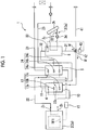
Fig. 1 is an overall configuration diagram of a water heating device of a first embodiment of the present invention. -
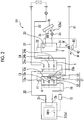
Fig. 2 is an overall configuration diagram of a water heating device of a second embodiment of the present invention. -
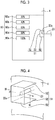
Fig. 3 is a side view of a first hot water storage tank in the second embodiment of the present invention. -
Fig. 4 is a perspective view illustrating a flow regulation member in the second embodiment of the present invention. -
Fig. 5 is a perspective view illustrating a flow regulation member in a first modification example of the second embodiment of the present invention. -
Fig. 6 is a perspective view illustrating a flow regulation member in a second modification example of the second embodiment of the present invention. -
Fig. 7 is an overall configuration diagram of a water heating device of a third embodiment of the present invention. - Hereinafter, a water heating device (heating device) 1 of an embodiment of the present invention will be described.
- As illustrated in
Fig. 1 , the water heating device 1 of the present embodiment is provided with a firstheat exchange part 2 and a secondheat exchange part 3 provided in parallel, a first hot water storage tank (first storage tank) 4 storing water (heating target liquid) W performing heat exchange with the firstheat exchange part 2, a third hot water storage tank (third storage tank) 6 storing the water W performing heat exchange with the secondheat exchange part 3, and a second hot water storage tank (second storage tank) 5 connected between the first hot water storage tank (first storage tank) 4 and the third hot water storage tank (third storage tank) 6. - The first
heat exchange part 2 has a firstrefrigerant circuit 2a in which CO2 (carbon dioxide) circulates as a first refrigerant RF1. The firstrefrigerant circuit 2a is a heat pump having a compressor (not illustrated), a heat exchanger, piping 3c, and the like. CO2 circulates in the firstrefrigerant circuit 2a while repeating condensation and evaporation. The water W is heated and discharged from anoutlet 2c after the water W is introduced from aninlet 2b of the firstheat exchange part 2. - The first hot
water storage tank 4 stores the water (hot water) W. Afirst outlet pipe 10 is connected to the lower portion of the first hotwater storage tank 4. Thefirst outlet pipe 10 is connected to theinlet 2b of the firstheat exchange part 2. The water W that is cold and the water (hot water) W that is warm are stored in the lower and upper portions in the first hotwater storage tank 4, respectively. Accordingly, the water W that has a relatively low temperature is introduced from thefirst outlet pipe 10 to theinlet 2b of the firstheat exchange part 2. Afirst connection pipe 11 is connected to the upper portion of the first hotwater storage tank 4. The water (hot water) W that has a relatively high temperature flows out from thefirst connection pipe 11. - A
supply pipe 41 is provided below the first hotwater storage tank 4 so that the water W can be introduced from an external water W supply source (such as a water supply (not illustrated)). - A
first temperature sensor 13 is provided on the side wall surface of the first hotwater storage tank 4. A plurality of the first temperature sensors 13 (three in the present embodiment) are provided at intervals in the height direction. The threefirst temperature sensors 13 are referred to as an upperfirst temperature sensor 13a, a middlefirst temperature sensor 13b, and a lowerfirst temperature sensor 13c. The number of thefirst temperature sensors 13 and the positions of disposition of thefirst temperature sensors 13 can be appropriately set in accordance with operating conditions and the structure of the first hotwater storage tank 4. - The second hot
water storage tank 5 stores the water (hot water) W. Thefirst connection pipe 11 connected to the upper portion of the first hotwater storage tank 4 is connected to the lower portion of the second hotwater storage tank 5. As a result, the water (hot water) W that has a relatively high temperature is capable of flowing into the first hotwater storage tank 4 from the second hotwater storage tank 5. Asecond inlet pipe 22 is connected to the second hotwater storage tank 5. Thesecond inlet pipe 22 is connected to theoutlet 2c of the firstheat exchange part 2. As a result, the water (hot water) W is introduced into the second hotwater storage tank 5 from the upper portion of the second hotwater storage tank 5 after the water (hot water) W is heated at the firstheat exchange part 2. - A
water intake pipe 21 is connected to the upper portion of the second hotwater storage tank 5 so that the water (hot water) W in the second hotwater storage tank 5 can be extracted and used. The second hotwater storage tank 5 is provided with arecycle line 23, which is a pipeline, so that the water (hot water) W extracted from thewater intake pipe 21 and used is capable of flowing into the second hotwater storage tank 5. In the present embodiment, therecycle line 23 is connected to the side wall surface of the second hotwater storage tank 5 and open to the inner portion of the second hotwater storage tank 5. - A
second temperature sensor 24 is provided on the side wall surface of the second hotwater storage tank 5. A plurality of the second temperature sensors 24 (three in the present embodiment) are provided at intervals in the height direction. The threesecond temperature sensors 24 are referred to as an uppersecond temperature sensor 24a, a middlesecond temperature sensor 24b, and a lowersecond temperature sensor 24c. The number of thesecond temperature sensors 24 and the positions of disposition of thesecond temperature sensors 24 can be appropriately set in accordance with operating conditions and the structure of the second hotwater storage tank 5. - An
operation control unit 15 including an MPU or the like is connected to thefirst temperature sensor 13 and thesecond temperature sensor 24. Theoperation control unit 15 acquires measured values (temperature of the water W) at thefirst temperature sensor 13 and thesecond temperature sensor 24 and performs operation control (such as compressor rotation speed control) on the firstheat exchange part 2 on the basis of the measured values. Specifically, theoperation control unit 15 operates the firstheat exchange part 2 in a case where the measured value of the upperfirst temperature sensor 13a is less than a predetermined first temperature. In other words, theoperation control unit 15 maintains a state where the measured values (temperature of the water W) of the uppersecond temperature sensor 24a, the middlesecond temperature sensor 24b, and the lowersecond temperature sensor 24c are equal to or greater than a predetermined temperature without exception (operation control step). - Although the "predetermined temperature" may be 60 degrees or more and 90 degrees or less, the "predetermined temperature" may be a temperature of at least 60 degrees.
- The second
heat exchange part 3 is provided independently of the firstheat exchange part 2. In the present embodiment, the secondheat exchange part 3 has the piping 3c through which brine (antifreeze) or the like circulates as a second refrigerant RF2, asolar collector 3b heating the second refrigerant, and a secondrefrigerant circuit 3a having apump 3d pumping the second refrigerant RF2. - The third hot water storage tank 6 stores the water (hot water) W. A
third inlet pipe 31 is connected to the lower portion of the third hot water storage tank 6. Thethird inlet pipe 31 is provided so as to branch from thesupply pipe 41, and the water W from the supply source (water supply) can be introduced from the lower portion of the third hot water storage tank 6. The third hot water storage tank 6 performs heat exchange with the second refrigerant RF2 of the secondheat exchange part 3 and is heated by solar heat. The water W that is cold and the water (hot water) W that is warm are stored in the lower and upper portions in the third hot water storage tank 6, respectively. Asecond connection pipe 32 is connected to the upper portion of the third hot water storage tank 6. Thesecond connection pipe 32 is connected to the second hotwater storage tank 5. The water (hot water) W that has a relatively high temperature flows out from thesecond connection pipe 32 toward the second hotwater storage tank 5. - A
third temperature sensor 33 is provided on the side wall surface of the upper portion of the third hot water storage tank 6. The position of disposition of thethird temperature sensor 33 can be appropriately set in accordance with operating conditions and the structure of the third hot water storage tank 6. - A switching
valve 42 such as a three-way valve is provided at the part of thethird inlet pipe 31 that branches from thesupply pipe 41. Avalve control unit 43 including an MPU or the like is connected to the switchingvalve 42. - The switching
valve 42 is capable of selectively introducing the water W circulating via thesupply pipe 41 from the supply source into the third hot water storage tank 6 or the first hotwater storage tank 4. - Specifically, the
valve control unit 43 causes the water W from the supply source to be introduced into the third hot water storage tank 6 when the temperature of the water (hot water) W in the third hot water storage tank 6 is equal to or higher than the predetermined temperature. When the temperature of the water (hot water) W in the third hot water storage tank 6 is lower than the predetermined temperature, thevalve control unit 43 operates the switchingvalve 42 such that the water W from the supply source is introduced into the first hot water storage tank 4 (introduction step). - According to the water heating device 1 of the present embodiment described above, the temperature of the water W in the third hot water storage tank 6 falls in a case where the available heat quantity at the second
heat exchange part 3 utilizing natural energy is insufficient and the amount of heat exchange with the water W is insufficient. Then, the switchingvalve 42 is operated by thevalve control unit 43 such that the temperature of the water W in the third hot water storage tank 6 (measured value at the third temperature sensor 33) does not fall below a predetermined temperature and the water W from the external supply source can be introduced into the first hotwater storage tank 4 without being introduced into the third hot water storage tank 6. - In this case, the water W in the first hot
water storage tank 4 is caused to exchange heat with the firstheat exchange part 2 in which the first refrigerant RF1, which is CO2, circulates. The water W is heated as a result, and then the water W is introduced into the second hotwater storage tank 5. Accordingly, even when the heat exchange amount at the secondheat exchange part 3 is insufficient, it is possible to store the water W in the second hotwater storage tank 5 after heating the water W by using the firstheat exchange part 2, which is a heat pump using a CO2 refrigerant, such that the shortage of the heat exchange amount is covered. - Subsequently selected is whether to store the heated water (hot water) W in the first hot
water storage tank 4 in the upper portion of the second hotwater storage tank 5 from theoutlet 2c of the firstheat exchange part 2 or to push out the water (hot water) W heated in the third hot water storage tank 6 from the upper portion of the third hot water storage tank 6 and introduce the water into the second hotwater storage tank 5. As a result, the water (hot water) W having a predetermined temperature is stored in the second hotwater storage tank 5. As a result, the water W (hot water) W having the predetermined temperature can be extracted from the upper portion of the second hotwater storage tank 5 and used without being affected by a variation in heat exchange amount at the secondheat exchange part 3. - The pre-heat exchange water W from the external supply source is introduced into the first hot
water storage tank 4 from below, and the water W from the lower portion of the first hotwater storage tank 4 is introduced into theinlet 2b of the firstheat exchange part 2. The water (hot water) W in the first hotwater storage tank 4 is high in temperature in the upper portion and low in temperature in the lower portion. Accordingly, the low-temperature water W in the lower portion of the first hotwater storage tank 4 is introduced into the firstheat exchange part 2. The heat pump using the CO2 refrigerant has a COP increasing as the temperature of theinlet 2b falls. Accordingly, the CO2 water heater of the present embodiment can be operated in a state where the efficiency of the firstheat exchange part 2 is high. - The temperature of the water W extracted from the second hot
water storage tank 5 can be kept at a predetermined temperature at all times by the operation of the firstheat exchange part 2 being controlled by theoperation control unit 15. For example, it is possible to extract the water (hot water) W that a user can use with ease by keeping the temperature of the water (hot water) W extracted from the second hotwater storage tank 5 at 60 degrees or more and 90 degrees or less. In addition, bacterial development such as Legionella development can be prevented. - Next, a
water heating device 1A of a second embodiment of the present invention will be described. In the following description of the second embodiment, parts identical to those of the first embodiment are denoted by the same reference numerals so that the same description is not repeated. The second embodiment is different from the first embodiment in that aflow regulation member 51 is provided in the first hotwater storage tank 4 in addition to the configuration of the first embodiment. - In the present embodiment, a plurality of hot water storage
amount detection sensors 60 are provided at intervals in the height direction on the side wall surface of the first hotwater storage tank 4. In the present embodiment, five hot water storage amount detection sensors 60 (60a, 60b, 60c, 60d, and 60e) are provided, by the 20% downward, up to the height position where the amount of hot water storage reaches 100% from 20% (seeFig. 3 ). - As illustrated in
Figs. 2 to 4 , theflow regulation member 51 is provided in the first hotwater storage tank 4 so as to protrude from the inner surface of the side wall of the first hotwater storage tank 4 correspondingly to the position where therecycle line 23 is connected. - More specifically, the
flow regulation member 51 has a heightdirection regulation portion 52 disposed above and below anopening portion 23a of therecycle line 23 toward the first hotwater storage tank 4 and a facingdirection regulation portion 53 provided continuously with the heightdirection regulation portion 52. - The
recycle line 23 is provided so as to protrude into the first hotwater storage tank 4 through, for example, the side wall surface of the first hotwater storage tank 4. - The height
direction regulation portion 52 has a plate shape. A pair of the heightdirection regulation portions 52 are provided along the direction of extension of therecycle line 23 so as to sandwich theopening portion 23a of therecycle line 23 from above and below. The heightdirection regulation portion 52 below theopening portion 23a is disposed above the hot water storageamount detection sensor 60e at the height position of 100%. The heightdirection regulation portion 52 above theopening portion 23a is disposed below the hot water storageamount detection sensor 60a at the height position of 20%. - The facing
direction regulation portion 53 has a plate shape extending in the height direction and interconnects the pair of heightdirection regulation portions 52 inside the first hotwater storage tank 4. The facingdirection regulation portion 53 has a surface facing the inner surface of the side wall of the first hotwater storage tank 4 so as to face the outflow direction of the water W flowing out from the recycle line 23 (width direction of the first hotwater storage tank 4 in the present embodiment). - According to the
water heating device 1A of the present embodiment described above, the heightdirection regulation portion 52 of theflow regulation member 51 is capable of regulating the temperature-lowered water W from therecycle line 23 heading upward or downward as it is without being stored in the first hotwater storage tank 4 and flowing out from the first hotwater storage tank 4. - Accordingly, it is possible to prevent the water W from the
recycle line 23 from being directly introduced into theinlet 2b of the firstheat exchange part 2, and thus it is possible to avoid an increase in the temperature of the water W at theinlet 2b of the firstheat exchange part 2 in a case where the temperature of the water W from therecycle line 23 is higher than the temperature of the water W from the external supply source and it is possible to avoid a decline in the COP of the firstheat exchange part 2. - In addition, it is possible to avoid the water W from the
recycle line 23 that has a temperature lower than the predetermined temperature flowing from the upper portion of the first hotwater storage tank 4 into the second hotwater storage tank 5 as it is. Accordingly, it is possible to avoid the temperature of the water (hot water) W that is extracted from the upper portion of the second hotwater storage tank 5 falling below the above predetermined temperature. - Further, it is possible to cause the water W from the
recycle line 23 to collide with the facingdirection regulation portion 53 and diffuse in the first hotwater storage tank 4. Accordingly, the water W from the recycle line can be re-heated in the first hotwater storage tank 4 after the temperature of the water W has fallen below a predetermined temperature. - In the present embodiment, the height
direction regulation portion 52 may be provided only below theopening portion 23a of therecycle line 23 as illustrated inFig. 5 . In addition, the heightdirection regulation portion 52 may be provided only above theopening portion 23a unlike in the case ofFig. 5 . In other words, theflow regulation member 51 may be L-shaped in cross section. - Further, in the present embodiment, effects similar to those of the
flow regulation member 51 can be obtained even when the tip of therecycle line 23, which is a pipeline, is bent into an L shape as illustrated inFig. 6 . - Next, a
water heating device 1B of a third embodiment of the present invention will be described. In the following description of the third embodiment, parts identical to those of the first and second embodiments are denoted by the same reference numerals so that the same description is not repeated. Of the configurations of the second embodiment, the secondheat exchange part 3, the third hot water storage tank 6, the switchingvalve 42, and thevalve control unit 43 are not provided in the third embodiment. - In other words, the
water heating device 1B is provided with the firstheat exchange part 2, the first hotwater storage tank 4, the second hotwater storage tank 5, therecycle line 23, and theflow regulation member 51 as illustrated inFig. 7 . - According to the
water heating device 1B of the present embodiment, it is possible to prevent the water W from therecycle line 23 that is higher in temperature than the water W from the external supply source from being directly introduced into theinlet 2b of the firstheat exchange part 2, and thus it is possible to avoid a decline in the COP of the firstheat exchange part 2. - In addition, it is possible to avoid the water W from the
recycle line 23 that has a temperature lower than the predetermined temperature flowing from the upper portion of the first hotwater storage tank 4 into the second hotwater storage tank 5 as it is. Accordingly, it is possible to avoid the temperature of the water (hot water) W that is extracted from the upper portion of the second hotwater storage tank 5 falling below the above predetermined temperature. - Further, it is possible to cause the water W from the
recycle line 23 to collide with the facingdirection regulation portion 53 and diffuse in the first hotwater storage tank 4. Accordingly, the water W from therecycle line 23 can be re-heated in the first hotwater storage tank 4 after the temperature of the water W has fallen below a predetermined temperature. - Although embodiments of the present invention have been described in detail with reference to the drawings, the configurations of each embodiment, combinations of the configurations, and the like are examples, and addition, omission, substitution, and other changes in terms of configuration are possible without departing from the spirit of the present invention. The present invention is not limited by the embodiments. The present invention is limited only by the claims.
- For example, the switching
valve 42 may be manually operated irrespective of thevalve control unit 43. - According to the heating device and the heating method described above, it is possible to achieve efficiency enhancement while obtaining a heating target liquid that has a predetermined temperature.
-
- 1, 1A, 1B Water heating device (heating device)
- 2 First heat exchange part
- 2a First refrigerant circuit
- 2b Inlet
- 2c Outlet
- 3 Second heat exchange part
- 3a Second refrigerant circuit
- 3b Solar collector
- 3c Piping
- 4 First hot water storage tank (first storage tank)
- 5 Second hot water storage tank (second storage tank)
- 6 Third hot water storage tank (third storage tank)
- 10 First outlet pipe
- 11 First connection pipe
- 13 First temperature sensor
- 13a Upper first temperature sensor
- 13b Middle first temperature sensor
- 13c Lower first temperature sensor
- 15 Operation control unit
- 21 Water intake pipe
- 22 Second inlet pipe
- 23 Recycle line
- 23a Opening portion
- 24 Second temperature sensor
- 24a Upper second temperature sensor
- 24b Middle second temperature sensor
- 24c Lower second temperature sensor
- 31 Third inlet pipe
- 32 Second connection pipe
- 33 Third temperature sensor
- 41 Supply pipe
- 42 Switching valve
- 43 Valve control unit
- 51 Flow regulation member
- 52 Height direction regulation portion
- 53 Facing direction regulation portion
- 60 (60a, 60b, 60c, 60d, 60e) Hot water storage amount detection sensor
- W Water (heating target liquid)
- RF1 First refrigerant
- RF2 Second refrigerant
Claims (9)
- A heating device comprising:a first heat exchange part including a first refrigerant circuit in which CO2 as a first refrigerant circulates while repeating condensation and evaporation, heating a heating target liquid introduced from an inlet, and discharging the heating target liquid from an outlet;a first storage tank storing the heating target liquid and having a lower portion connected to the inlet of the first heat exchange part;a second storage tank storing the heating target liquid, having a lower portion connected to an upper portion of the first storage tank, having an upper portion connected to the outlet of the first heat exchange part, and allowing the heating target liquid having a predetermined temperature to be extracted from the upper portion;a third storage tank storing the heating target liquid and having an upper portion connected to the second storage tank;a second heat exchange part provided in parallel to the first heat exchange part, including a second refrigerant circuit in which a second refrigerant circulates, and heating the heating target liquid in the third storage tank;a switching valve capable of introducing the heating target liquid from an outside into the lower portion of the first storage tank or a lower portion of the third storage tank; anda valve control unit operating the switching valve such that the heating target liquid from the outside is introduced into the third storage tank when the temperature of the heating target liquid in the upper portion of the third storage tank is equal to or higher than the predetermined temperature and the heating target liquid from the outside is introduced into the first storage tank when the temperature of the heating target liquid in the upper portion of the third storage tank is lower than the predetermined temperature.
- The heating device according to Claim 1, further comprising:a first temperature sensor measuring the temperature of the heating target liquid in the first storage tank at a predetermined height position corresponding to the upper portion of the first storage tank;a second temperature sensor measuring the temperature of the heating target liquid in the second storage tank at a predetermined height position in the upper portion of the second storage tank; andan operation control unit controlling operation of the first heat exchange part in accordance with a measured value of the first temperature sensor such that a measured value of the second temperature sensor becomes equal to or greater than the predetermined temperature.
- The heating device according to Claim 1 or 2, wherein the predetermined temperature is 60 degrees or more and 90 degrees or less.
- The heating device according to any one of Claims 1 to 3, wherein the second heat exchange part has a solar collector and the heating target liquid in the third storage tank is heated by the solar collector.
- The heating device according to any one of Claims 1 to 4, further comprising:a recycle line connected to the first storage tank and allowing the heating target liquid to be introduced into the first storage tank after the heating target liquid is extracted from the second storage tank and used; anda flow regulation member disposed above, below, or above and below an opening portion of the recycle line in the first storage tank and protruding from an inner surface of the first storage tank.
- A heating device comprising:a first heat exchange part including a first refrigerant circuit in which CO2 as a first refrigerant circulates while repeating condensation and evaporation, heating a heating target liquid introduced from an inlet, and discharging the heating target liquid from an outlet;a first storage tank storing the heating target liquid and having a lower portion connected to the inlet of the first heat exchange part;a second storage tank storing the heating target liquid, having a lower portion connected to an upper portion of the first storage tank, having an upper portion connected to the outlet of the first heat exchange part, and allowing the heating target liquid having a predetermined temperature to be extracted from the upper portion;a recycle line connected to the first storage tank and allowing the heating target liquid to be introduced into the first storage tank after the heating target liquid is extracted from the second storage tank and used; anda flow regulation member disposed above, below, or above and below an opening portion of the recycle line in the first storage tank and protruding from an inner surface of the first storage tank.
- The heating device according to Claim 5 or 6, wherein the flow regulation member includes
a height direction regulation portion disposed above, below, or above and below the opening portion, and
a facing direction regulation portion continuous with the height direction regulation portion inside the first storage tank and facing the opening portion. - A heating method for heating a heating target liquid with a device, the device including
a first heat exchange part including a first refrigerant circuit in which CO2 as a first refrigerant circulates while repeating condensation and evaporation, heating the heating target liquid introduced from an inlet, and discharging the heating target liquid from an outlet,
a first storage tank storing the heating target liquid and having a lower portion connected to the inlet of the first heat exchange part,
a second storage tank storing the heating target liquid, having a lower portion connected to an upper portion of the first storage tank, having an upper portion connected to the outlet of the first heat exchange part, and allowing the heating target liquid having a predetermined temperature to be extracted from the upper portion,
a third storage tank storing the heating target liquid and having an upper portion connected to the second storage tank, and
a second heat exchange part provided in parallel to the first heat exchange part, including a second refrigerant circuit in which a second refrigerant circulates, and heating the heating target liquid in the third storage tank,
the heating method comprising:
a step of causing the heating target liquid from an outside to be introduced into the third storage tank when the temperature of the heating target liquid in the third storage tank is equal to or higher than the predetermined temperature and the heating target liquid from the outside to be introduced into the first storage tank when the temperature of the heating target liquid is lower than the predetermined temperature. - The heating method according to Claim 8, further comprising:
a step of controlling operation of the first heat exchange part in accordance with the temperature of the heating target liquid in the first storage tank at a predetermined height position in the upper portion of the first storage tank such that the temperature of the heating target liquid in the second storage tank becomes equal to or higher than the predetermined temperature.
Applications Claiming Priority (2)
| Application Number | Priority Date | Filing Date | Title |
|---|---|---|---|
| JP2017067578A JP2018169109A (en) | 2017-03-30 | 2017-03-30 | Heating apparatus and heating method |
| PCT/JP2018/011986 WO2018181101A1 (en) | 2017-03-30 | 2018-03-26 | Heating device and heating method |
Publications (2)
| Publication Number | Publication Date |
|---|---|
| EP3531039A1 true EP3531039A1 (en) | 2019-08-28 |
| EP3531039A4 EP3531039A4 (en) | 2020-04-01 |
Family
ID=63675780
Family Applications (1)
| Application Number | Title | Priority Date | Filing Date |
|---|---|---|---|
| EP18775970.9A Withdrawn EP3531039A4 (en) | 2017-03-30 | 2018-03-26 | HEATING DEVICE AND HEATING METHOD |
Country Status (4)
| Country | Link |
|---|---|
| EP (1) | EP3531039A4 (en) |
| JP (1) | JP2018169109A (en) |
| CN (1) | CN109997001A (en) |
| WO (1) | WO2018181101A1 (en) |
Families Citing this family (1)
| Publication number | Priority date | Publication date | Assignee | Title |
|---|---|---|---|---|
| CN116358165A (en) * | 2023-03-20 | 2023-06-30 | 湖南清渟科技有限公司 | Artificial intelligence-based double water tank heating method and its applied water purifier |
Family Cites Families (13)
| Publication number | Priority date | Publication date | Assignee | Title |
|---|---|---|---|---|
| US4388578A (en) | 1980-07-07 | 1983-06-14 | Cynex Manufacturing Corporation | Power factor controller |
| DE10201396B4 (en) * | 2002-01-16 | 2004-06-24 | Robert Bosch Gmbh | Hot water system with solar storage and stratified storage |
| JP3918807B2 (en) * | 2003-02-20 | 2007-05-23 | 株式会社デンソー | Hot water storage type electric water heater |
| JP2005121331A (en) * | 2003-10-20 | 2005-05-12 | Matsushita Electric Ind Co Ltd | Water heater |
| JP4513754B2 (en) * | 2006-01-30 | 2010-07-28 | 株式会社デンソー | Hybrid hot water supply system |
| CN101813335B (en) * | 2010-02-11 | 2012-03-21 | 沈阳联美蓝天环保新能源有限公司 | Central heating method and system using solar and heat pump to replace parts of traditional heat sources |
| JP5549376B2 (en) * | 2010-05-26 | 2014-07-16 | 東京電力株式会社 | Hot water system |
| CN201926102U (en) * | 2010-12-14 | 2011-08-10 | 中通客车控股股份有限公司 | Heat storage water heating system |
| CN202370769U (en) * | 2011-11-22 | 2012-08-08 | 榆林学院 | A compressed CO2 solar heat and power cogeneration device |
| JP5945714B2 (en) * | 2012-02-03 | 2016-07-05 | パナソニックIpマネジメント株式会社 | Heat pump water heater |
| CN203231522U (en) * | 2013-03-27 | 2013-10-09 | 吴涛阳 | Double-heat-source water heater |
| JP6504646B2 (en) * | 2014-04-28 | 2019-04-24 | 昭和鉄工株式会社 | Storage tank internal structure |
| JP2017067578A (en) | 2015-09-30 | 2017-04-06 | 日立オートモティブシステムズ株式会社 | Replenishment fuel amount calculation device |
-
2017
- 2017-03-30 JP JP2017067578A patent/JP2018169109A/en active Pending
-
2018
- 2018-03-26 WO PCT/JP2018/011986 patent/WO2018181101A1/en not_active Ceased
- 2018-03-26 CN CN201880004465.0A patent/CN109997001A/en active Pending
- 2018-03-26 EP EP18775970.9A patent/EP3531039A4/en not_active Withdrawn
Also Published As
| Publication number | Publication date |
|---|---|
| WO2018181101A1 (en) | 2018-10-04 |
| EP3531039A4 (en) | 2020-04-01 |
| JP2018169109A (en) | 2018-11-01 |
| CN109997001A (en) | 2019-07-09 |
Similar Documents
| Publication | Publication Date | Title |
|---|---|---|
| US10697648B2 (en) | Heating and hot water supply system | |
| JP3918807B2 (en) | Hot water storage type electric water heater | |
| JP6289440B2 (en) | Heat pump water heater | |
| KR101621168B1 (en) | Hot water supply system | |
| JP6107958B2 (en) | Heat storage system | |
| KR101479877B1 (en) | Storage type hot water supply device | |
| CN101900416A (en) | Constant temperature variable energy-saving water heater | |
| KR101587268B1 (en) | Cooling/heating and hot water suppling system using geothermy heat pump | |
| JP2014016075A (en) | Hybrid system | |
| KR100685341B1 (en) | Heat pump water heater | |
| JP6533717B2 (en) | Hot water supply system | |
| KR101471309B1 (en) | Storage type hot water supply device | |
| JP3985773B2 (en) | Hot water storage water heater | |
| JP2015183911A (en) | Heat storage device | |
| JP2011185552A (en) | Bath hot water filling device | |
| JP7294087B2 (en) | heat pump water heater | |
| JP2018136103A (en) | Hot water storage type water heater | |
| JP5585513B2 (en) | Hot water system | |
| WO2018181101A1 (en) | Heating device and heating method | |
| JP2004177102A (en) | Hot water storage system | |
| JP5617946B2 (en) | Hot water storage water heater | |
| JP2002022270A (en) | Heat pump water heater | |
| JP2004232912A (en) | Heat pump water heater | |
| JP2011252675A (en) | Heat pump water heater | |
| WO2024231664A1 (en) | Energy buffering using a heat pump |
Legal Events
| Date | Code | Title | Description |
|---|---|---|---|
| STAA | Information on the status of an ep patent application or granted ep patent |
Free format text: STATUS: THE INTERNATIONAL PUBLICATION HAS BEEN MADE |
|
| PUAI | Public reference made under article 153(3) epc to a published international application that has entered the european phase |
Free format text: ORIGINAL CODE: 0009012 |
|
| STAA | Information on the status of an ep patent application or granted ep patent |
Free format text: STATUS: REQUEST FOR EXAMINATION WAS MADE |
|
| 17P | Request for examination filed |
Effective date: 20190521 |
|
| AK | Designated contracting states |
Kind code of ref document: A1 Designated state(s): AL AT BE BG CH CY CZ DE DK EE ES FI FR GB GR HR HU IE IS IT LI LT LU LV MC MK MT NL NO PL PT RO RS SE SI SK SM TR |
|
| AX | Request for extension of the european patent |
Extension state: BA ME |
|
| RIC1 | Information provided on ipc code assigned before grant |
Ipc: F24H 4/04 20060101ALI20191105BHEP Ipc: F24D 3/00 20060101ALI20191105BHEP Ipc: F25B 27/00 20060101ALI20191105BHEP Ipc: F24H 9/20 20060101ALI20191105BHEP Ipc: F25B 1/00 20060101ALI20191105BHEP Ipc: F24H 4/02 20060101AFI20191105BHEP Ipc: F24H 1/00 20060101ALI20191105BHEP Ipc: F24D 19/10 20060101ALI20191105BHEP Ipc: F24H 9/00 20060101ALI20191105BHEP Ipc: F24H 1/18 20060101ALI20191105BHEP |
|
| A4 | Supplementary search report drawn up and despatched |
Effective date: 20200228 |
|
| RIC1 | Information provided on ipc code assigned before grant |
Ipc: F24H 9/20 20060101ALI20200224BHEP Ipc: F25B 27/00 20060101ALI20200224BHEP Ipc: F24H 4/04 20060101ALI20200224BHEP Ipc: F24D 3/00 20060101ALI20200224BHEP Ipc: F25B 1/00 20060101ALI20200224BHEP Ipc: F24H 4/02 20060101AFI20200224BHEP Ipc: F24D 19/10 20060101ALI20200224BHEP Ipc: F24H 1/00 20060101ALI20200224BHEP Ipc: F24H 9/00 20060101ALI20200224BHEP Ipc: F24H 1/18 20060101ALI20200224BHEP |
|
| DAV | Request for validation of the european patent (deleted) | ||
| DAX | Request for extension of the european patent (deleted) | ||
| STAA | Information on the status of an ep patent application or granted ep patent |
Free format text: STATUS: THE APPLICATION IS DEEMED TO BE WITHDRAWN |
|
| 18D | Application deemed to be withdrawn |
Effective date: 20200929 |