EP3530960B1 - Pompe a doigt - Google Patents
Pompe a doigt Download PDFInfo
- Publication number
- EP3530960B1 EP3530960B1 EP19158280.8A EP19158280A EP3530960B1 EP 3530960 B1 EP3530960 B1 EP 3530960B1 EP 19158280 A EP19158280 A EP 19158280A EP 3530960 B1 EP3530960 B1 EP 3530960B1
- Authority
- EP
- European Patent Office
- Prior art keywords
- finger
- volute
- blade
- pump according
- axis
- Prior art date
- Legal status (The legal status is an assumption and is not a legal conclusion. Google has not performed a legal analysis and makes no representation as to the accuracy of the status listed.)
- Active
Links
Images


Classifications
-
- F—MECHANICAL ENGINEERING; LIGHTING; HEATING; WEAPONS; BLASTING
- F04—POSITIVE - DISPLACEMENT MACHINES FOR LIQUIDS; PUMPS FOR LIQUIDS OR ELASTIC FLUIDS
- F04D—NON-POSITIVE-DISPLACEMENT PUMPS
- F04D29/00—Details, component parts, or accessories
- F04D29/40—Casings; Connections of working fluid
- F04D29/42—Casings; Connections of working fluid for radial or helico-centrifugal pumps
- F04D29/426—Casings; Connections of working fluid for radial or helico-centrifugal pumps especially adapted for liquid pumps
- F04D29/4293—Details of fluid inlet or outlet
-
- F—MECHANICAL ENGINEERING; LIGHTING; HEATING; WEAPONS; BLASTING
- F04—POSITIVE - DISPLACEMENT MACHINES FOR LIQUIDS; PUMPS FOR LIQUIDS OR ELASTIC FLUIDS
- F04D—NON-POSITIVE-DISPLACEMENT PUMPS
- F04D1/00—Radial-flow pumps, e.g. centrifugal pumps; Helico-centrifugal pumps
- F04D1/04—Helico-centrifugal pumps
-
- F—MECHANICAL ENGINEERING; LIGHTING; HEATING; WEAPONS; BLASTING
- F04—POSITIVE - DISPLACEMENT MACHINES FOR LIQUIDS; PUMPS FOR LIQUIDS OR ELASTIC FLUIDS
- F04D—NON-POSITIVE-DISPLACEMENT PUMPS
- F04D29/00—Details, component parts, or accessories
- F04D29/40—Casings; Connections of working fluid
- F04D29/42—Casings; Connections of working fluid for radial or helico-centrifugal pumps
- F04D29/426—Casings; Connections of working fluid for radial or helico-centrifugal pumps especially adapted for liquid pumps
-
- F—MECHANICAL ENGINEERING; LIGHTING; HEATING; WEAPONS; BLASTING
- F04—POSITIVE - DISPLACEMENT MACHINES FOR LIQUIDS; PUMPS FOR LIQUIDS OR ELASTIC FLUIDS
- F04D—NON-POSITIVE-DISPLACEMENT PUMPS
- F04D29/00—Details, component parts, or accessories
- F04D29/40—Casings; Connections of working fluid
- F04D29/42—Casings; Connections of working fluid for radial or helico-centrifugal pumps
- F04D29/44—Fluid-guiding means, e.g. diffusers
- F04D29/445—Fluid-guiding means, e.g. diffusers especially adapted for liquid pumps
-
- F—MECHANICAL ENGINEERING; LIGHTING; HEATING; WEAPONS; BLASTING
- F04—POSITIVE - DISPLACEMENT MACHINES FOR LIQUIDS; PUMPS FOR LIQUIDS OR ELASTIC FLUIDS
- F04D—NON-POSITIVE-DISPLACEMENT PUMPS
- F04D7/00—Pumps adapted for handling specific fluids, e.g. by selection of specific materials for pumps or pump parts
- F04D7/02—Pumps adapted for handling specific fluids, e.g. by selection of specific materials for pumps or pump parts of centrifugal type
- F04D7/04—Pumps adapted for handling specific fluids, e.g. by selection of specific materials for pumps or pump parts of centrifugal type the fluids being viscous or non-homogenous
- F04D7/045—Pumps adapted for handling specific fluids, e.g. by selection of specific materials for pumps or pump parts of centrifugal type the fluids being viscous or non-homogenous with means for comminuting, mixing stirring or otherwise treating
-
- F—MECHANICAL ENGINEERING; LIGHTING; HEATING; WEAPONS; BLASTING
- F05—INDEXING SCHEMES RELATING TO ENGINES OR PUMPS IN VARIOUS SUBCLASSES OF CLASSES F01-F04
- F05D—INDEXING SCHEME FOR ASPECTS RELATING TO NON-POSITIVE-DISPLACEMENT MACHINES OR ENGINES, GAS-TURBINES OR JET-PROPULSION PLANTS
- F05D2250/00—Geometry
- F05D2250/50—Inlet or outlet
- F05D2250/52—Outlet
Definitions
- a pump comprising an impeller having at least one vane.
- the impeller is surrounded by a volute.
- a deflector, projecting towards the inside of the pump, is fixed to the volute upstream, in the direction of rotation of the impeller, of a groove made in the volute.
- the deflector has a surface facing the blade while being at a shredding distance.
- Deflector pumps are known from the documents US 2003/215,331 and US 2010/119,365 and speak WO 2017/198509 .
- the document EP 1 357 294 describes a pump according to the preamble of claim 1 and the document EP 3 246 574 also forms part of the state of the art.
- This chopper pump has the disadvantage that in particular the deflector and the blades wear out quickly, since they must jointly have a cutting effect.
- the invention overcomes this drawback by means of a pump, which grinds only occasionally, but which essentially guides the fibrous materials, such as wipes, out of the pump, without necessarily having to cut them first.
- the pump is characterized in that , seen from the side opposite the suction, the angle between the imaginary plane tangent to the spout and passing through the axis and an imaginary straight line, perpendicular to the axis and passing through the point, the furthest from the axis, from the intersection of the upper surface with the side attack surface, is between 110 and 140°.
- the axis of the pump is vertical, but the pump can be placed so that its axis is inclined or horizontal.
- the volute nose is the inner edge of the discharge nozzle, which is the furthest downstream in the direction in which liquid is conveyed.
- the suction bottom if present, is considered part of the volute.
- the finger can be attached to it.
- the volute is preferably spiral. The radial distance between its outer wall and its inner wall increases from upstream to downstream from the finger to the beak.
- the groove is curved from upstream to downstream from the entrance to the exit of the groove through the inside wall of the volute. It extends over an angle of approximately 80° to 100° and rises at an angle of 15 to 30° from inlet to outlet.
- the wipe thus exits the space between the impeller and the volute at a point as close as possible to the discharge pipe, thus being conveyed as well as possible outside the pump, and this all the better as the volute is spiral, which means that the distance between the impeller and the volute increases in the direction of rotation of the impeller from the nose of the volute to the discharge pipe.
- the wipe thus follows as short a path as possible between the suction and the groove and thus has less opportunity to curl up and, by stacking with other wipes, to cause clogging.
- the angle between the tangent to the downstream edge of the entrance to the groove and the edge between the upper surface and the lateral leading surface is between 180 and 150°.
- the longitudinal direction of the groove is thus, as far as possible, in the extension of the upper surface, which prevents a wipe from getting stuck before entering the groove.
- the upper surface When the vane or vanes are tilted relative to the axis, the upper surface turns its convexity towards the vane. When the blade is in a plane perpendicular to the axis, the upper surface is flat.
- the upper surface of the finger is convex and turns its convexity towards the blade and the tangent to the upper surface, at its most downstream point, forms, depending on the rotational position of the blade, an angle of 50 to 140° with the tangent to the vane at the point vertically aligned with said most downstream point. Moreover, this angle increases as a function of the rotation of the impeller described by the arrow F when looking at the impeller from the suction side.
- a wipe is best deflected by the finger in the groove and is discharged into the pump without the pump having to perform a cutting effect.
- the particular shape of the finger in secateurs allows a clean cut of the fabric and thus avoids the creation of tow as much as possible.
- the angle between the imaginary tangent plane to the leading face passing through the line of intersection of the leading face and the upper face and the tangent plane imaginary of the upper face passing the line of intersection of the leading face of the upper face is between 60 and 90°.
- a pump according to the invention is so effective that one can be satisfied with having only one groove and one finger. There is thus less damage to the hydraulic characteristics of the pump.
- the finger has in particular the shape of a pyramid with three curved side faces.
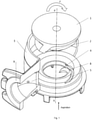
- the pump shown in figure 1 comprises an impeller 1 of axis X, X' vertical having two blades 2.
- the impeller is driven in rotation in the direction of the arrow F by the output shaft of a motor, not shown.
- the blades 2 are inclined on the axis X, X'.
- the impeller 1 is surrounded by a volute 3.
- the liquid to be conveyed enters via a suction at the bottom of the pump into the volute 3.
- a finger 4 is fixed to the volute 3.
- a groove 5 is provided in the volute 3 and ranges from the gap between impeller 1 and the volute 3 inside the volute 3.
- a discharge pipe 9 starts from the volute 3 from a spout 10.
- the finger 4 has a convex upper surface 8, the greater part of which is 0.3 mm from the blades 2 when the latter pass in front of the finger 4.
- the tangent 11 to the upper surface 8 at its most downstream point forms , depending on the rotational position of the blades 2, an angle ⁇ of 90° with the tangent 12 to the blade 2 at the point aligned vertically with the said point 7.
- the angle ⁇ between the tangent to the downstream edge of the entrance to the groove 5 and the edge between the upper surface 8 and the lateral attack surface 6 is 170°.
- Finger 4 shown in figure 4 is pyramid-shaped having the upper surface 8, the lateral attack surface 6, and a lateral trailing surface 14, all curved.
- the figure 7 shows that there is an angle ⁇ 1 between the side attack face 6 of the finger 4 and a vertical axis YY, which is between 0 and 15°. It also shows an angle ⁇ 2 between the upper face 8 of the finger and a horizontal axis ZZ, which is between 0 and 15°. The combination of the two angles gives ⁇ 3, which is an acute angle between 90 and 60°.
Landscapes
- Engineering & Computer Science (AREA)
- Mechanical Engineering (AREA)
- General Engineering & Computer Science (AREA)
- Structures Of Non-Positive Displacement Pumps (AREA)
- Jet Pumps And Other Pumps (AREA)
Description
- Au brevet
français 1 511 657 - On connaît des pompes à déflecteur par les documents
US 2003/215,331 etUS 2010/119,365 et par leWO 2017/198 509 . - Le document
EP 1 357 294 décrit une pompe suivant le préambule de la revendication 1 et le documentEP 3 246 574 fait aussi partie de l'état de la technique. - Cette pompe dilacératrice a l'inconvénient que notamment le déflecteur et les aubes s'usent rapidement, puisqu'elles doivent conjointement avoir un effet de coupe.
- L'invention pallie cet inconvénient par une pompe, qui n'est dilacératrice qu'à l'occasion, mais qui, pour l'essentiel, guide les matières fibreuses, telles que des lingettes, en-dehors de la pompe, sans avoir nécessairement à les couper auparavant.
- La pompe suivant l'invention comprend :
- un impulseur monté tournant autour d'un axe vertical et ayant au moins une aube,
- une volute fixe ayant un bec et entourant l'impulseur,
- un doigt fixé à la volute juste en aval de l'entrée d'une rainure traversante ménagée dans la paroi intérieure de la volute, en saillie en dessous de l'aube en direction de l'axe et ayant une surface supérieure, dont au moins une partie, notamment au moins 50%, est à une distance de l'aube de 0,05 à 0,5 mm, et une surface latérale d'attaque.
- La pompe est caractérisée en ce que , vu du côté opposé à l'aspiration, l'angle entre le plan imaginaire tangent au bec et passant par l'axe et une droite imaginaire, perpendiculaire à l'axe et passant par le point, le plus éloigné de l'axe, de l'intersection de la surface supérieure avec la surface latérale d'attaque, est compris entre 110 et 140°.
- Pour faciliter l'exposé de l'invention, on considère que l'axe de la pompe est vertical, mais on peut mettre la pompe de manière à ce que son axe soit incliné ou horizontal.
- Les mots aval et amont s'entendent dans le présent mémoire seulement par rapport au tronçon de parcours sur la volute ayant la distance la plus courte entre la rainure et le bec en tournant dans le sens de rotation de l'impulseur et non plus lorsque l'on parcourt par la pensée l'arc le plus grand entre le bec et la rainure. Le doigt juste en aval de l'entrée de la rainure signifie ainsi qu'avant d'entrer par la pensée sur le tronçon de parcours le plus court, on trouve d'abord la rainure, puis le doigt, celui-ci étant notamment immédiatement au bord aval de l'entrée de la rainure.
- Le bec de la volute est l'arête intérieure de la tubulure de refoulement, qui est la plus en aval dans le sens où du liquide est véhiculé. Le fond d'aspiration, éventuellement présent, est considéré comme faisant partie de la volute. Le doigt peut y être fixé. La volute est, de préférence, en colimaçon. La distance radiale entre sa paroi extérieure et sa paroi intérieure augmente d'amont en aval du doigt au bec. La rainure est courbée de l'amont vers l'aval de l'entrée à la sortie de la rainure à travers la paroi intérieure de la volute. Elle s'étend sur un angle d'environ 80° à 100° et est montante suivant un angle de 15 à 30° de l'entrée à la sortie. Grâce à l'invention, la lingette sort ainsi de l'espace compris entre l'impulseur et la volute en un point aussi proche que possible de la tubulure de refoulement en étant ainsi véhiculée aussi bien que possible à l'extérieur de la pompe, et cela d'autant mieux que la volute est en colimaçon, ce qui signifie que la distance entre l'impulseur et la volute s'accroît dans le sens de rotation de l'impulseur du bec de la volute à la tubulure de refoulement. La lingette suit ainsi un trajet aussi court que possible entre l'aspiration et la rainure et a ainsi moins l'occasion de s'enrouler et, par empilement avec d'autres lingettes, de provoquer un bouchage.
- De préférence, l'angle entre la tangente au bord aval de l'entrée de la rainure et le bord entre la surface supérieure et la surface latérale d'attaque est compris entre 180 et 150°. La direction longitudinale de la rainure est ainsi, autant que possible, dans le prolongement de la surface supérieure, ce qui évite qu'une lingette se coince avant d'entrer dans la rainure.
- Lorsque l'aube ou les aubes sont inclinées par rapport à l'axe, la surface supérieure tourne sa convexité vers l'aube. Lorsque l'aube est dans un plan perpendiculaire à l'axe, la surface supérieure est plane.
- De préférence, la surface supérieure du doigt est convexe et tourne sa convexité vers l'aube et la tangente à la surface supérieure, en son point le plus aval, fait, suivant la position en rotation de l'aube, un angle de 50 à 140° avec la tangente à l'aube en le point aligné verticalement sur ledit point le plus en aval. De plus, cet angle croît en fonction de la rotation de l'impulseur décrit par la flèche F lorsque l'on regarde l'impulseur du côté de l'aspiration.
- Grâce à cela, une lingette est déviée au mieux par le doigt dans la rainure et est évacuée dans la pompe sans que la pompe ait à effectuer un effet de coupe. Cependant, si un blocage survient, la forme particulière du doigt (en sécateur) permet une découpe nette du tissu et évite ainsi au mieux la création de filasse.
- Pour mieux couper une lingette en cas de bouchage, il vaut mieux que l'angle entre le plan tangent imaginaire à la face d'attaque passant par la ligne d'intersection de la face d'attaque et de la face supérieure et le plan tangent imaginaire de la face supérieure passant la ligne d'intersection de la face d'attaque de la face supérieure soit compris entre 60 et 90°.
- Une pompe suivant l'invention est si efficace que l'on peut se contenter de n'avoir qu'une seule rainure et qu'un seul doigt. On porte ainsi moins atteinte aux caractéristiques hydrauliques de la pompe.
- Le doigt a notamment la forme d'une pyramide à trois faces latérales courbées.
- Aux dessins annexés, donné uniquement à titre d'exemple :
- la figure 1
- est une vue partielle en perspective éclatée avec arrachement d'une pompe suivant l'invention ;
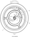
- la figure 2
- est une vue, vue du côté aspiration de la pompe sens dessus dessous par rapport à la
figure 1 ; - la figure 3
- est une vue en coupe de la pompe vue d'en haut ;
- la figure 4
- est une vue de dessous en perspective du doigt ;
- la figure 5
- est une vue de dessus en perspective du doigt ;
- la figure 6
- est une vue de dessus du doigt et
- la figure 7
- est une vue en coupe suivant la ligne A-A de la
figure 6 . - La pompe représentée à la
figure 1 comporte un impulseur 1 d'axe X, X' vertical ayant deux aubes 2. L'impulseur est entraîné en rotation dans le sens de la flèche F par l'arbre de sortie d'un moteur non représenté. Les aubes 2 sont inclinées sur l'axe X, X'. L'impulseur 1 est entouré d'une volute 3. Le liquide à véhiculer entre par une aspiration au bas de la pompe dans la volute 3. Un doigt 4 est fixé à la volute 3. Une rainure 5 est ménagée dans la volute 3 et va de l'intervalle entre l'impulseur 1 et la volute 3 à l'intérieur de la volute 3. Une tubulure 9 de refoulement part de la volute 3 à partir d'un bec 10. - Le doigt 4 a une surface 8 supérieure convexe, dont la plus grande partie est à 0,3 mm des aubes 2 lorsque celles-ci passent devant le doigt 4. La tangente 11 à la surface 8 supérieure en son point le plus en aval fait, suivant la position en rotation des aubes 2, un angle β de 90° avec la tangente 12 à l'aube 2 en le point aligné verticalement avec ledit point 7.
- Comme le montre la
figure 3 , l'angle Y entre le plan P imaginaire tangent au bec 10 passant par l'axe X, X' et une droite imaginaire D passant par l'intersection de la surface 8 supérieure avec la surface 6 latérale d'attaque du doigt 4 et perpendiculaire à l'axe X, X' et au point le plus éloigné de l'axe X,X' (=point 13) est de 130°. Le doigt 4 est ainsi à huit heures si l'on considère que le bec 10 est à midi. - L'angle δ entre la tangente au bord aval de l'entrée de la rainure 5 et le bord entre la surface 8 supérieure et la surface 6 latérale d'attaque est de 170°.
- Le doigt 4 représenté à la
figure 4 est en forme de pyramide ayant la surface 8 supérieure, la surface 6 latérale d'attaque, et une surface 14 latérale de fuite, toutes courbées. - La
figure 7 montre qu'il y a un angle ξ1 entre la face 6 d'attaque latérale du doigt 4 et un axe vertical Y-Y, qui est compris entre 0 et 15°. Elle montre également un angle ξ2 entre la face 8 supérieure du doigt et un axe horizontal Z-Z, qui est compris entre 0 et 15°. La combinaison des deux angles donne ξ3, qui est un angle aigu compris entre 90 et 60°.
Claims (8)
- Pompe comprenant- un impulseur (1) monté tournant autour d'un axe (X, X') vertical et ayant au moins une aube (2),- une volute (3) fixe ayant un bec (10) et entourant l'impulseur (1), et- un doigt (4) fixé à la volute (3) juste en aval de l'entrée d'une rainure (5) traversante ménagée dans la paroi intérieure de la volute (3), en saillie en dessous de l'aube (2) en direction de l'axe (X, X') et ayant une surface (8) supérieure, dont au moins une partie est à une distance de l'aube (2) de 0,05 à 0,5 mm, et une surface (6) latérale d'attaque,caractérisé en ce que, vu du côté opposé à l'aspiration, l'angle (Y) entre un plan (P) tangent au bec (10) et passant par l'axe (X, X') et une droite (D) imaginaire, perpendiculaire à l'axe (X, X') et passant par le point, le plus éloigné de l'axe (X, X'), de l'intersection de la surface (8) supérieure du doigt (4) avec la surface (6) latérale d'attaque, est compris entre 110 et 140°.
- Pompe suivant la revendication précédente, caractérisée en ce que la volute (3) est en colimaçon.
- Pompe suivant l'une des revendications précédentes , caractérisée en ce que l'angle (δ) entre la tangente au bord aval de l'entrée de la rainure (5) et le bord entre la surface (8) supérieure et la surface (6) latérale d'attaque est compris entre 180° et 150°.
- Pompe suivant l'une des revendications précédentes , caractérisée en ce que- la surface (8) supérieure est convexe et tourne sa convexité vers l'aube (2),- la tangente (11) à la surface (8) supérieure, en son point le plus en aval, fait, suivant la position en rotation de l'aube (2), un angle (β) de 50 à 140° avec la tangente (12) à l'aube (2) en le point aligné verticalement avec ledit point le plus en aval.
- Pompe suivant l'une des revendications précédentes, caractérisée en ce qu'il n'y a qu'une seule rainure (5) et qu'un seul doigt (4).
- Pompe suivant l'une des revendications précédentes, caractérisée en ce que la partie du doigt (4), qui est à une distance de 0,1 à 0,5 mm de l'aube (2), représente au moins 50% de la surface (8) supérieure.
- Pompe suivant l'une des revendications précédentes, caractérisée en ce que le doigt (4) a la forme d'une pyramide à trois faces latérales courbées.
- Pompe suivant l'une des revendications précédentes , caractérisée en ce que l'angle entre le plan tangent à la face (6) d'attaque passant par la ligne d'intersection de la face (6) d'attaque et de la face (8) supérieure et le plan tangent de la face (8) supérieure passant la ligne d'intersection de la face (6) d'attaque de la face (8) supérieure est compris entre 60 et 90°.
Priority Applications (2)
| Application Number | Priority Date | Filing Date | Title |
|---|---|---|---|
| EP21213941.4A EP4006356B1 (fr) | 2018-02-22 | 2019-02-20 | Pompe à doigt |
| PL19158280T PL3530960T3 (pl) | 2018-02-22 | 2019-02-20 | Pompa z palcem zgarniającym |
Applications Claiming Priority (1)
| Application Number | Priority Date | Filing Date | Title |
|---|---|---|---|
| FR1870195A FR3078116B1 (fr) | 2018-02-22 | 2018-02-22 | Pompe a doigt |
Related Child Applications (2)
| Application Number | Title | Priority Date | Filing Date |
|---|---|---|---|
| EP21213941.4A Division-Into EP4006356B1 (fr) | 2018-02-22 | 2019-02-20 | Pompe à doigt |
| EP21213941.4A Division EP4006356B1 (fr) | 2018-02-22 | 2019-02-20 | Pompe à doigt |
Publications (2)
| Publication Number | Publication Date |
|---|---|
| EP3530960A1 EP3530960A1 (fr) | 2019-08-28 |
| EP3530960B1 true EP3530960B1 (fr) | 2022-02-16 |
Family
ID=61913482
Family Applications (2)
| Application Number | Title | Priority Date | Filing Date |
|---|---|---|---|
| EP19158280.8A Active EP3530960B1 (fr) | 2018-02-22 | 2019-02-20 | Pompe a doigt |
| EP21213941.4A Active EP4006356B1 (fr) | 2018-02-22 | 2019-02-20 | Pompe à doigt |
Family Applications After (1)
| Application Number | Title | Priority Date | Filing Date |
|---|---|---|---|
| EP21213941.4A Active EP4006356B1 (fr) | 2018-02-22 | 2019-02-20 | Pompe à doigt |
Country Status (12)
| Country | Link |
|---|---|
| US (2) | US10895267B2 (fr) |
| EP (2) | EP3530960B1 (fr) |
| JP (1) | JP2019143630A (fr) |
| KR (1) | KR20190101291A (fr) |
| CN (1) | CN110185655B (fr) |
| AU (1) | AU2019200954B2 (fr) |
| BR (1) | BR102019003250B1 (fr) |
| CA (1) | CA3032955A1 (fr) |
| FR (1) | FR3078116B1 (fr) |
| PL (2) | PL3530960T3 (fr) |
| SA (1) | SA119400481B1 (fr) |
| ZA (1) | ZA201901050B (fr) |
Families Citing this family (25)
| Publication number | Priority date | Publication date | Assignee | Title |
|---|---|---|---|---|
| US8048089B2 (en) | 2005-12-30 | 2011-11-01 | Edge Systems Corporation | Apparatus and methods for treating the skin |
| WO2014151104A1 (fr) | 2013-03-15 | 2014-09-25 | Edge Systems Llc | Dispositifs, systèmes et procédés pour le traitement de la peau |
| EP2240099B1 (fr) | 2008-01-04 | 2018-02-21 | Edge Systems LLC | Appareil pour le traitement de la peau |
| WO2009097451A1 (fr) | 2008-01-29 | 2009-08-06 | Edge Systems Corporation | Appareil et procédé de traitement de la peau |
| US10179229B2 (en) | 2014-12-23 | 2019-01-15 | Edge Systems Llc | Devices and methods for treating the skin using a porous member |
| EP3795204B1 (fr) | 2014-12-23 | 2023-10-25 | HydraFacial LLC | Dispositif de traitement de la peau à l'aide d'une bille |
| EP3899285B1 (fr) * | 2018-12-21 | 2024-05-22 | Grundfos Holding A/S | Pompe centrifuge avec racleur |
| WO2021025035A1 (fr) | 2019-08-05 | 2021-02-11 | 住友重機械工業株式会社 | Excavatrice |
| JP7276099B2 (ja) | 2019-11-26 | 2023-05-18 | 株式会社鶴見製作所 | 無閉塞ポンプ |
| US11291474B2 (en) | 2020-01-06 | 2022-04-05 | Ed F. Nicolas | Skin treatment tool applicator tip |
| EP3988793B1 (fr) * | 2020-10-26 | 2024-08-07 | Xylem Europe GmbH | Pompe ayant un siège de roue doté d'une broche de guidage |
| EP3988794B1 (fr) * | 2020-10-26 | 2024-07-31 | Xylem Europe GmbH | Siège de roue pour une pompe dotée d'une broche de guidage |
| EP4102080B1 (fr) * | 2021-06-08 | 2025-01-01 | Xylem Europe GmbH | Pompe et unité hydraulique d'une pompe |
| JP7724097B2 (ja) | 2021-07-21 | 2025-08-15 | 株式会社荏原製作所 | ポンプケーシングおよびポンプ |
| CN115788919A (zh) | 2021-09-09 | 2023-03-14 | 创科无线普通合伙 | 潜水泵 |
| WO2023039524A1 (fr) | 2021-09-10 | 2023-03-16 | Hydrafacial Llc | Dispositifs, systèmes et méthodes pour le traitement de la peau |
| USD1016615S1 (en) | 2021-09-10 | 2024-03-05 | Hydrafacial Llc | Container for a skin treatment device |
| USD1065551S1 (en) | 2021-09-10 | 2025-03-04 | Hydrafacial Llc | Skin treatment device |
| US20260036132A1 (en) * | 2021-10-04 | 2026-02-05 | KSB SE & Co. KGaA | Centrifugal Pump Having Wear-Resistant Wear Plate With Scraper Element |
| USD1042807S1 (en) | 2021-10-11 | 2024-09-17 | Hydrafacial Llc | Skin treatment tip |
| USD1116120S1 (en) | 2021-10-11 | 2026-03-03 | Hydrafacial Llc | Skin treatment device |
| USD1112778S1 (en) | 2022-03-04 | 2026-02-10 | Hydrafacial Llc | Light therapy device for skin care |
| USD1084369S1 (en) | 2023-02-10 | 2025-07-15 | Hydrafacial Llc | Skin treatment tip |
| JP2026061090A (ja) * | 2024-09-30 | 2026-04-09 | 株式会社荏原製作所 | ポンプ |
| JP2026085507A (ja) | 2024-11-13 | 2026-05-25 | 株式会社荏原製作所 | ポンプ |
Family Cites Families (13)
| Publication number | Priority date | Publication date | Assignee | Title |
|---|---|---|---|---|
| FR1511657A (fr) | 1966-12-23 | 1968-02-02 | Pierre Mengin Ets | Perfectionnements aux pompes dilacératrices |
| DE10204459A1 (de) * | 2002-02-05 | 2003-08-07 | Bosch Gmbh Robert | Flüssigkeitspumpe |
| SE524048C2 (sv) * | 2002-04-26 | 2004-06-22 | Itt Mfg Enterprises Inc | Anordning vid pump |
| DE102004058458B3 (de) * | 2004-12-03 | 2006-05-18 | Brinkmann Pumpen K.H. Brinkmann Gmbh & Co. Kg | Pumpe mit Schneidlaufrad |
| SE527818C2 (sv) * | 2005-06-17 | 2006-06-13 | Itt Mfg Enterprises Inc | Pump för pumpning av förorenad vätska |
| SE531147C2 (sv) * | 2007-05-15 | 2009-01-07 | Itt Mfg Enterprises Inc | Dränkbar centrifugalpump med normal- och uttömningsdrifttillstånd |
| TW201118254A (en) * | 2009-11-25 | 2011-06-01 | Sunny King Machinery Co Ltd | Anti-turbulent structure for screw pump |
| CN102536835B (zh) * | 2012-03-21 | 2014-04-09 | 江苏大学 | 固液两相流螺旋离心泵 |
| WO2014024305A1 (fr) * | 2012-08-10 | 2014-02-13 | 三菱電機株式会社 | Ventilateur-hélice, ventilateur, climatiseur et unité d'extérieur pour fourniture d'eau chaude munis de celui-ci |
| US10724534B2 (en) * | 2014-11-26 | 2020-07-28 | Tc1 Llc | Pump and method for mixed flow blood pumping |
| KR101832131B1 (ko) * | 2015-10-26 | 2018-02-26 | 주식회사 경동나비엔 | 보일러용 펌프 |
| CN105697269A (zh) * | 2016-01-24 | 2016-06-22 | 况常松 | 节能高效环保加油机泵 |
| DK3246574T3 (en) | 2016-05-17 | 2019-04-08 | Xylem Europe Gmbh | Pump for pumping fluid as well as a forest wheel device |
-
2018
- 2018-02-22 FR FR1870195A patent/FR3078116B1/fr active Active
-
2019
- 2019-02-07 CA CA3032955A patent/CA3032955A1/fr active Pending
- 2019-02-12 AU AU2019200954A patent/AU2019200954B2/en active Active
- 2019-02-14 US US16/276,309 patent/US10895267B2/en active Active
- 2019-02-18 BR BR102019003250-2A patent/BR102019003250B1/pt active IP Right Grant
- 2019-02-19 KR KR1020190018940A patent/KR20190101291A/ko not_active Withdrawn
- 2019-02-19 ZA ZA2019/01050A patent/ZA201901050B/en unknown
- 2019-02-20 EP EP19158280.8A patent/EP3530960B1/fr active Active
- 2019-02-20 PL PL19158280T patent/PL3530960T3/pl unknown
- 2019-02-20 EP EP21213941.4A patent/EP4006356B1/fr active Active
- 2019-02-20 PL PL21213941.4T patent/PL4006356T3/pl unknown
- 2019-02-21 SA SA119400481A patent/SA119400481B1/ar unknown
- 2019-02-21 CN CN201910130044.9A patent/CN110185655B/zh active Active
- 2019-02-21 JP JP2019029708A patent/JP2019143630A/ja active Pending
-
2020
- 2020-10-28 US US17/082,206 patent/US20210040957A1/en not_active Abandoned
Also Published As
| Publication number | Publication date |
|---|---|
| AU2019200954B2 (en) | 2024-11-14 |
| FR3078116A1 (fr) | 2019-08-23 |
| EP4006356B1 (fr) | 2024-10-16 |
| CN110185655B (zh) | 2022-06-17 |
| US10895267B2 (en) | 2021-01-19 |
| CA3032955A1 (fr) | 2019-08-22 |
| BR102019003250A2 (pt) | 2019-09-10 |
| US20210040957A1 (en) | 2021-02-11 |
| BR102019003250B1 (pt) | 2024-01-16 |
| CN110185655A (zh) | 2019-08-30 |
| RU2019104420A (ru) | 2020-08-18 |
| PL4006356T3 (pl) | 2025-03-31 |
| FR3078116B1 (fr) | 2021-09-10 |
| KR20190101291A (ko) | 2019-08-30 |
| AU2019200954A1 (en) | 2019-09-05 |
| ZA201901050B (en) | 2024-07-31 |
| JP2019143630A (ja) | 2019-08-29 |
| EP4006356C0 (fr) | 2024-10-16 |
| US20190257320A1 (en) | 2019-08-22 |
| SA119400481B1 (ar) | 2021-12-13 |
| EP4006356A1 (fr) | 2022-06-01 |
| EP3530960A1 (fr) | 2019-08-28 |
| PL3530960T3 (pl) | 2022-06-13 |
Similar Documents
| Publication | Publication Date | Title |
|---|---|---|
| EP4006356B1 (fr) | Pompe à doigt | |
| CN101198793B (zh) | 泵抽机 | |
| EP1916385B1 (fr) | Nageoire de plateforme de soufflante | |
| FR2582746A1 (fr) | Rotor de pompe, notamment rotor de pompe centrifuge | |
| JP5070039B2 (ja) | スクリュー遠心ポンプおよびスクリュー遠心ポンプを使用した、固体添加物で満たされた液体の運搬方法 | |
| JPS6213518B2 (fr) | ||
| CN114245849B (zh) | 用于污水泵的叶轮进口边缘的刮除元件 | |
| FR3036139A1 (fr) | Turbomachine comportant un melangeur a lobes avec ecopes. | |
| EP2085620A1 (fr) | Compresseur de turboréacteur | |
| JP7724097B2 (ja) | ポンプケーシングおよびポンプ | |
| AU2008296843B2 (en) | Wear plate for a centrifugal pump | |
| EP1303703B1 (fr) | Broyeur sanitaire | |
| US20040081557A1 (en) | Pump impeller | |
| EP3635182B1 (fr) | Tête de coupe à fonction d'aspiration et son procédé d'utilisation | |
| EP0465312B1 (fr) | Dispositif de triage d'un mélange de pate à papier et de contaminants | |
| JPH0730751B2 (ja) | ポンプ | |
| EP1592883A1 (fr) | Dispositif pour ameliiorer le rendement des pales d'eolienne | |
| RU2785617C2 (ru) | Насос | |
| FR2724695A1 (fr) | Pompe centrifuge a anneau d'entree | |
| FR2540944A1 (fr) | Pompe centrifuge pour liquides contenant des materiaux solides, notamment pour le transport de suspensions de fibres | |
| BE542190A (fr) | ||
| FR2499639A1 (fr) | Pompe centrifuge a volute et a roue mobile radiale ou semi-axiale |
Legal Events
| Date | Code | Title | Description |
|---|---|---|---|
| PUAI | Public reference made under article 153(3) epc to a published international application that has entered the european phase |
Free format text: ORIGINAL CODE: 0009012 |
|
| STAA | Information on the status of an ep patent application or granted ep patent |
Free format text: STATUS: THE APPLICATION HAS BEEN PUBLISHED |
|
| AK | Designated contracting states |
Kind code of ref document: A1 Designated state(s): AL AT BE BG CH CY CZ DE DK EE ES FI FR GB GR HR HU IE IS IT LI LT LU LV MC MK MT NL NO PL PT RO RS SE SI SK SM TR |
|
| AX | Request for extension of the european patent |
Extension state: BA ME |
|
| STAA | Information on the status of an ep patent application or granted ep patent |
Free format text: STATUS: REQUEST FOR EXAMINATION WAS MADE |
|
| 17P | Request for examination filed |
Effective date: 20200228 |
|
| RBV | Designated contracting states (corrected) |
Designated state(s): AL AT BE BG CH CY CZ DE DK EE ES FI FR GB GR HR HU IE IS IT LI LT LU LV MC MK MT NL NO PL PT RO RS SE SI SK SM TR |
|
| STAA | Information on the status of an ep patent application or granted ep patent |
Free format text: STATUS: EXAMINATION IS IN PROGRESS |
|
| 17Q | First examination report despatched |
Effective date: 20210910 |
|
| GRAP | Despatch of communication of intention to grant a patent |
Free format text: ORIGINAL CODE: EPIDOSNIGR1 |
|
| STAA | Information on the status of an ep patent application or granted ep patent |
Free format text: STATUS: GRANT OF PATENT IS INTENDED |
|
| INTG | Intention to grant announced |
Effective date: 20211110 |
|
| GRAS | Grant fee paid |
Free format text: ORIGINAL CODE: EPIDOSNIGR3 |
|
| GRAA | (expected) grant |
Free format text: ORIGINAL CODE: 0009210 |
|
| STAA | Information on the status of an ep patent application or granted ep patent |
Free format text: STATUS: THE PATENT HAS BEEN GRANTED |
|
| AK | Designated contracting states |
Kind code of ref document: B1 Designated state(s): AL AT BE BG CH CY CZ DE DK EE ES FI FR GB GR HR HU IE IS IT LI LT LU LV MC MK MT NL NO PL PT RO RS SE SI SK SM TR |
|
| REG | Reference to a national code |
Ref country code: GB Ref legal event code: FG4D Free format text: NOT ENGLISH |
|
| REG | Reference to a national code |
Ref country code: CH Ref legal event code: EP |
|
| REG | Reference to a national code |
Ref country code: DE Ref legal event code: R096 Ref document number: 602019011565 Country of ref document: DE |
|
| REG | Reference to a national code |
Ref country code: AT Ref legal event code: REF Ref document number: 1469046 Country of ref document: AT Kind code of ref document: T Effective date: 20220315 |
|
| REG | Reference to a national code |
Ref country code: IE Ref legal event code: FG4D Free format text: LANGUAGE OF EP DOCUMENT: FRENCH |
|
| REG | Reference to a national code |
Ref country code: SE Ref legal event code: TRGR |
|
| REG | Reference to a national code |
Ref country code: NL Ref legal event code: FP |
|
| REG | Reference to a national code |
Ref country code: LT Ref legal event code: MG9D |
|
| PG25 | Lapsed in a contracting state [announced via postgrant information from national office to epo] |
Ref country code: RS Free format text: LAPSE BECAUSE OF FAILURE TO SUBMIT A TRANSLATION OF THE DESCRIPTION OR TO PAY THE FEE WITHIN THE PRESCRIBED TIME-LIMIT Effective date: 20220216 Ref country code: PT Free format text: LAPSE BECAUSE OF FAILURE TO SUBMIT A TRANSLATION OF THE DESCRIPTION OR TO PAY THE FEE WITHIN THE PRESCRIBED TIME-LIMIT Effective date: 20220616 Ref country code: NO Free format text: LAPSE BECAUSE OF FAILURE TO SUBMIT A TRANSLATION OF THE DESCRIPTION OR TO PAY THE FEE WITHIN THE PRESCRIBED TIME-LIMIT Effective date: 20220516 Ref country code: LT Free format text: LAPSE BECAUSE OF FAILURE TO SUBMIT A TRANSLATION OF THE DESCRIPTION OR TO PAY THE FEE WITHIN THE PRESCRIBED TIME-LIMIT Effective date: 20220216 Ref country code: IT Free format text: LAPSE BECAUSE OF NON-PAYMENT OF DUE FEES Effective date: 20220220 Ref country code: HR Free format text: LAPSE BECAUSE OF FAILURE TO SUBMIT A TRANSLATION OF THE DESCRIPTION OR TO PAY THE FEE WITHIN THE PRESCRIBED TIME-LIMIT Effective date: 20220216 Ref country code: ES Free format text: LAPSE BECAUSE OF FAILURE TO SUBMIT A TRANSLATION OF THE DESCRIPTION OR TO PAY THE FEE WITHIN THE PRESCRIBED TIME-LIMIT Effective date: 20220216 Ref country code: BG Free format text: LAPSE BECAUSE OF FAILURE TO SUBMIT A TRANSLATION OF THE DESCRIPTION OR TO PAY THE FEE WITHIN THE PRESCRIBED TIME-LIMIT Effective date: 20220516 |
|
| PG25 | Lapsed in a contracting state [announced via postgrant information from national office to epo] |
Ref country code: LV Free format text: LAPSE BECAUSE OF FAILURE TO SUBMIT A TRANSLATION OF THE DESCRIPTION OR TO PAY THE FEE WITHIN THE PRESCRIBED TIME-LIMIT Effective date: 20220216 Ref country code: GR Free format text: LAPSE BECAUSE OF FAILURE TO SUBMIT A TRANSLATION OF THE DESCRIPTION OR TO PAY THE FEE WITHIN THE PRESCRIBED TIME-LIMIT Effective date: 20220517 Ref country code: FI Free format text: LAPSE BECAUSE OF FAILURE TO SUBMIT A TRANSLATION OF THE DESCRIPTION OR TO PAY THE FEE WITHIN THE PRESCRIBED TIME-LIMIT Effective date: 20220216 |
|
| PG25 | Lapsed in a contracting state [announced via postgrant information from national office to epo] |
Ref country code: IS Free format text: LAPSE BECAUSE OF FAILURE TO SUBMIT A TRANSLATION OF THE DESCRIPTION OR TO PAY THE FEE WITHIN THE PRESCRIBED TIME-LIMIT Effective date: 20220617 |
|
| PG25 | Lapsed in a contracting state [announced via postgrant information from national office to epo] |
Ref country code: SM Free format text: LAPSE BECAUSE OF FAILURE TO SUBMIT A TRANSLATION OF THE DESCRIPTION OR TO PAY THE FEE WITHIN THE PRESCRIBED TIME-LIMIT Effective date: 20220216 Ref country code: SK Free format text: LAPSE BECAUSE OF FAILURE TO SUBMIT A TRANSLATION OF THE DESCRIPTION OR TO PAY THE FEE WITHIN THE PRESCRIBED TIME-LIMIT Effective date: 20220216 Ref country code: RO Free format text: LAPSE BECAUSE OF FAILURE TO SUBMIT A TRANSLATION OF THE DESCRIPTION OR TO PAY THE FEE WITHIN THE PRESCRIBED TIME-LIMIT Effective date: 20220216 Ref country code: EE Free format text: LAPSE BECAUSE OF FAILURE TO SUBMIT A TRANSLATION OF THE DESCRIPTION OR TO PAY THE FEE WITHIN THE PRESCRIBED TIME-LIMIT Effective date: 20220216 Ref country code: DK Free format text: LAPSE BECAUSE OF FAILURE TO SUBMIT A TRANSLATION OF THE DESCRIPTION OR TO PAY THE FEE WITHIN THE PRESCRIBED TIME-LIMIT Effective date: 20220216 Ref country code: CZ Free format text: LAPSE BECAUSE OF FAILURE TO SUBMIT A TRANSLATION OF THE DESCRIPTION OR TO PAY THE FEE WITHIN THE PRESCRIBED TIME-LIMIT Effective date: 20220216 |
|
| REG | Reference to a national code |
Ref country code: DE Ref legal event code: R097 Ref document number: 602019011565 Country of ref document: DE |
|
| PG25 | Lapsed in a contracting state [announced via postgrant information from national office to epo] |
Ref country code: MC Free format text: LAPSE BECAUSE OF FAILURE TO SUBMIT A TRANSLATION OF THE DESCRIPTION OR TO PAY THE FEE WITHIN THE PRESCRIBED TIME-LIMIT Effective date: 20220216 Ref country code: AL Free format text: LAPSE BECAUSE OF FAILURE TO SUBMIT A TRANSLATION OF THE DESCRIPTION OR TO PAY THE FEE WITHIN THE PRESCRIBED TIME-LIMIT Effective date: 20220216 |
|
| PLBE | No opposition filed within time limit |
Free format text: ORIGINAL CODE: 0009261 |
|
| STAA | Information on the status of an ep patent application or granted ep patent |
Free format text: STATUS: NO OPPOSITION FILED WITHIN TIME LIMIT |
|
| 26N | No opposition filed |
Effective date: 20221117 |
|
| PG25 | Lapsed in a contracting state [announced via postgrant information from national office to epo] |
Ref country code: IT Free format text: LAPSE BECAUSE OF NON-PAYMENT OF DUE FEES Effective date: 20220220 |
|
| PGRI | Patent reinstated in contracting state [announced from national office to epo] |
Ref country code: IT Effective date: 20220228 |
|
| PG25 | Lapsed in a contracting state [announced via postgrant information from national office to epo] |
Ref country code: SI Free format text: LAPSE BECAUSE OF FAILURE TO SUBMIT A TRANSLATION OF THE DESCRIPTION OR TO PAY THE FEE WITHIN THE PRESCRIBED TIME-LIMIT Effective date: 20220216 |
|
| PG25 | Lapsed in a contracting state [announced via postgrant information from national office to epo] |
Ref country code: MK Free format text: LAPSE BECAUSE OF FAILURE TO SUBMIT A TRANSLATION OF THE DESCRIPTION OR TO PAY THE FEE WITHIN THE PRESCRIBED TIME-LIMIT Effective date: 20220216 Ref country code: CY Free format text: LAPSE BECAUSE OF FAILURE TO SUBMIT A TRANSLATION OF THE DESCRIPTION OR TO PAY THE FEE WITHIN THE PRESCRIBED TIME-LIMIT Effective date: 20220216 |
|
| PG25 | Lapsed in a contracting state [announced via postgrant information from national office to epo] |
Ref country code: HU Free format text: LAPSE BECAUSE OF FAILURE TO SUBMIT A TRANSLATION OF THE DESCRIPTION OR TO PAY THE FEE WITHIN THE PRESCRIBED TIME-LIMIT; INVALID AB INITIO Effective date: 20190220 |
|
| PG25 | Lapsed in a contracting state [announced via postgrant information from national office to epo] |
Ref country code: MT Free format text: LAPSE BECAUSE OF FAILURE TO SUBMIT A TRANSLATION OF THE DESCRIPTION OR TO PAY THE FEE WITHIN THE PRESCRIBED TIME-LIMIT Effective date: 20220216 |
|
| PG25 | Lapsed in a contracting state [announced via postgrant information from national office to epo] |
Ref country code: TR Free format text: LAPSE BECAUSE OF FAILURE TO SUBMIT A TRANSLATION OF THE DESCRIPTION OR TO PAY THE FEE WITHIN THE PRESCRIBED TIME-LIMIT Effective date: 20220216 |
|
| REG | Reference to a national code |
Ref country code: CH Ref legal event code: U11 Free format text: ST27 STATUS EVENT CODE: U-0-0-U10-U11 (AS PROVIDED BY THE NATIONAL OFFICE) Effective date: 20260301 |
|
| PGFP | Annual fee paid to national office [announced via postgrant information from national office to epo] |
Ref country code: NL Payment date: 20260228 Year of fee payment: 8 Ref country code: LU Payment date: 20260220 Year of fee payment: 8 |
|
| PGFP | Annual fee paid to national office [announced via postgrant information from national office to epo] |
Ref country code: SE Payment date: 20260228 Year of fee payment: 8 |
|
| PGFP | Annual fee paid to national office [announced via postgrant information from national office to epo] |
Ref country code: GB Payment date: 20260226 Year of fee payment: 8 |
|
| PGFP | Annual fee paid to national office [announced via postgrant information from national office to epo] |
Ref country code: DE Payment date: 20260305 Year of fee payment: 8 Ref country code: IE Payment date: 20260220 Year of fee payment: 8 |
|
| PGFP | Annual fee paid to national office [announced via postgrant information from national office to epo] |
Ref country code: AT Payment date: 20260223 Year of fee payment: 8 |
|
| PGFP | Annual fee paid to national office [announced via postgrant information from national office to epo] |
Ref country code: BE Payment date: 20260225 Year of fee payment: 8 Ref country code: IT Payment date: 20260227 Year of fee payment: 8 |
|
| PGFP | Annual fee paid to national office [announced via postgrant information from national office to epo] |
Ref country code: FR Payment date: 20260225 Year of fee payment: 8 |
|
| PGFP | Annual fee paid to national office [announced via postgrant information from national office to epo] |
Ref country code: CH Payment date: 20260301 Year of fee payment: 8 |
|
| PGFP | Annual fee paid to national office [announced via postgrant information from national office to epo] |
Ref country code: PL Payment date: 20260202 Year of fee payment: 8 |