EP3530958A1 - Fan rotor blade and method of manufacturing same - Google Patents
Fan rotor blade and method of manufacturing same Download PDFInfo
- Publication number
- EP3530958A1 EP3530958A1 EP17862837.6A EP17862837A EP3530958A1 EP 3530958 A1 EP3530958 A1 EP 3530958A1 EP 17862837 A EP17862837 A EP 17862837A EP 3530958 A1 EP3530958 A1 EP 3530958A1
- Authority
- EP
- European Patent Office
- Prior art keywords
- core body
- fan rotor
- metal core
- rotor blade
- covering member
- Prior art date
- Legal status (The legal status is an assumption and is not a legal conclusion. Google has not performed a legal analysis and makes no representation as to the accuracy of the status listed.)
- Withdrawn
Links
- 238000004519 manufacturing process Methods 0.000 title claims description 18
- 239000002184 metal Substances 0.000 claims abstract description 58
- 229910052751 metal Inorganic materials 0.000 claims abstract description 58
- 229920005992 thermoplastic resin Polymers 0.000 claims abstract description 32
- 239000002131 composite material Substances 0.000 claims abstract description 28
- 239000012783 reinforcing fiber Substances 0.000 claims abstract description 17
- 238000000465 moulding Methods 0.000 claims description 20
- 238000010438 heat treatment Methods 0.000 claims description 13
- 238000010030 laminating Methods 0.000 claims description 7
- 239000006260 foam Substances 0.000 claims description 6
- 238000000034 method Methods 0.000 claims description 5
- 239000011162 core material Substances 0.000 description 53
- 239000013585 weight reducing agent Substances 0.000 description 5
- 229920002430 Fibre-reinforced plastic Polymers 0.000 description 4
- 239000011151 fibre-reinforced plastic Substances 0.000 description 4
- 230000005484 gravity Effects 0.000 description 3
- 239000004696 Poly ether ether ketone Substances 0.000 description 2
- 239000004697 Polyetherimide Substances 0.000 description 2
- 230000000694 effects Effects 0.000 description 2
- 229920006351 engineering plastic Polymers 0.000 description 2
- 229920001652 poly(etherketoneketone) Polymers 0.000 description 2
- 229920002530 polyetherether ketone Polymers 0.000 description 2
- 229920001601 polyetherimide Polymers 0.000 description 2
- 229920001187 thermosetting polymer Polymers 0.000 description 2
- 239000002759 woven fabric Substances 0.000 description 2
- 229920000049 Carbon (fiber) Polymers 0.000 description 1
- 229910000990 Ni alloy Inorganic materials 0.000 description 1
- 229910001069 Ti alloy Inorganic materials 0.000 description 1
- 229910045601 alloy Inorganic materials 0.000 description 1
- 239000000956 alloy Substances 0.000 description 1
- 239000004760 aramid Substances 0.000 description 1
- 229920006231 aramid fiber Polymers 0.000 description 1
- 239000004917 carbon fiber Substances 0.000 description 1
- 229910003460 diamond Inorganic materials 0.000 description 1
- 239000010432 diamond Substances 0.000 description 1
- 239000003365 glass fiber Substances 0.000 description 1
- 239000007769 metal material Substances 0.000 description 1
- 230000002093 peripheral effect Effects 0.000 description 1
- 239000004033 plastic Substances 0.000 description 1
- 229920003023 plastic Polymers 0.000 description 1
- 230000002787 reinforcement Effects 0.000 description 1
- 239000007787 solid Substances 0.000 description 1
Images


Classifications
-
- F—MECHANICAL ENGINEERING; LIGHTING; HEATING; WEAPONS; BLASTING
- F04—POSITIVE - DISPLACEMENT MACHINES FOR LIQUIDS; PUMPS FOR LIQUIDS OR ELASTIC FLUIDS
- F04D—NON-POSITIVE-DISPLACEMENT PUMPS
- F04D29/00—Details, component parts, or accessories
- F04D29/26—Rotors specially for elastic fluids
- F04D29/32—Rotors specially for elastic fluids for axial flow pumps
- F04D29/38—Blades
- F04D29/384—Blades characterised by form
-
- F—MECHANICAL ENGINEERING; LIGHTING; HEATING; WEAPONS; BLASTING
- F04—POSITIVE - DISPLACEMENT MACHINES FOR LIQUIDS; PUMPS FOR LIQUIDS OR ELASTIC FLUIDS
- F04D—NON-POSITIVE-DISPLACEMENT PUMPS
- F04D29/00—Details, component parts, or accessories
- F04D29/26—Rotors specially for elastic fluids
- F04D29/32—Rotors specially for elastic fluids for axial flow pumps
- F04D29/38—Blades
- F04D29/388—Blades characterised by construction
-
- B—PERFORMING OPERATIONS; TRANSPORTING
- B29—WORKING OF PLASTICS; WORKING OF SUBSTANCES IN A PLASTIC STATE IN GENERAL
- B29C—SHAPING OR JOINING OF PLASTICS; SHAPING OF MATERIAL IN A PLASTIC STATE, NOT OTHERWISE PROVIDED FOR; AFTER-TREATMENT OF THE SHAPED PRODUCTS, e.g. REPAIRING
- B29C43/00—Compression moulding, i.e. applying external pressure to flow the moulding material; Apparatus therefor
- B29C43/02—Compression moulding, i.e. applying external pressure to flow the moulding material; Apparatus therefor of articles of definite length, i.e. discrete articles
- B29C43/20—Making multilayered or multicoloured articles
-
- B—PERFORMING OPERATIONS; TRANSPORTING
- B29—WORKING OF PLASTICS; WORKING OF SUBSTANCES IN A PLASTIC STATE IN GENERAL
- B29C—SHAPING OR JOINING OF PLASTICS; SHAPING OF MATERIAL IN A PLASTIC STATE, NOT OTHERWISE PROVIDED FOR; AFTER-TREATMENT OF THE SHAPED PRODUCTS, e.g. REPAIRING
- B29C70/00—Shaping composites, i.e. plastics material comprising reinforcements, fillers or preformed parts, e.g. inserts
- B29C70/68—Shaping composites, i.e. plastics material comprising reinforcements, fillers or preformed parts, e.g. inserts by incorporating or moulding on preformed parts, e.g. inserts or layers, e.g. foam blocks
- B29C70/86—Incorporated in coherent impregnated reinforcing layers, e.g. by winding
-
- B—PERFORMING OPERATIONS; TRANSPORTING
- B29—WORKING OF PLASTICS; WORKING OF SUBSTANCES IN A PLASTIC STATE IN GENERAL
- B29D—PRODUCING PARTICULAR ARTICLES FROM PLASTICS OR FROM SUBSTANCES IN A PLASTIC STATE
- B29D24/00—Producing articles with hollow walls
- B29D24/002—Producing articles with hollow walls formed with structures, e.g. cores placed between two plates or sheets, e.g. partially filled
- B29D24/005—Producing articles with hollow walls formed with structures, e.g. cores placed between two plates or sheets, e.g. partially filled the structure having joined ribs, e.g. honeycomb
-
- B—PERFORMING OPERATIONS; TRANSPORTING
- B29—WORKING OF PLASTICS; WORKING OF SUBSTANCES IN A PLASTIC STATE IN GENERAL
- B29D—PRODUCING PARTICULAR ARTICLES FROM PLASTICS OR FROM SUBSTANCES IN A PLASTIC STATE
- B29D99/00—Subject matter not provided for in other groups of this subclass
- B29D99/0025—Producing blades or the like, e.g. blades for turbines, propellers, or wings
-
- B—PERFORMING OPERATIONS; TRANSPORTING
- B64—AIRCRAFT; AVIATION; COSMONAUTICS
- B64C—AEROPLANES; HELICOPTERS
- B64C1/00—Fuselages; Constructional features common to fuselages, wings, stabilising surfaces or the like
-
- F—MECHANICAL ENGINEERING; LIGHTING; HEATING; WEAPONS; BLASTING
- F01—MACHINES OR ENGINES IN GENERAL; ENGINE PLANTS IN GENERAL; STEAM ENGINES
- F01D—NON-POSITIVE DISPLACEMENT MACHINES OR ENGINES, e.g. STEAM TURBINES
- F01D5/00—Blades; Blade-carrying members; Heating, heat-insulating, cooling or antivibration means on the blades or the members
- F01D5/12—Blades
- F01D5/28—Selecting particular materials; Particular measures relating thereto; Measures against erosion or corrosion
- F01D5/282—Selecting composite materials, e.g. blades with reinforcing filaments
-
- F—MECHANICAL ENGINEERING; LIGHTING; HEATING; WEAPONS; BLASTING
- F02—COMBUSTION ENGINES; HOT-GAS OR COMBUSTION-PRODUCT ENGINE PLANTS
- F02C—GAS-TURBINE PLANTS; AIR INTAKES FOR JET-PROPULSION PLANTS; CONTROLLING FUEL SUPPLY IN AIR-BREATHING JET-PROPULSION PLANTS
- F02C7/00—Features, components parts, details or accessories, not provided for in, or of interest apart form groups F02C1/00 - F02C6/00; Air intakes for jet-propulsion plants
-
- F—MECHANICAL ENGINEERING; LIGHTING; HEATING; WEAPONS; BLASTING
- F04—POSITIVE - DISPLACEMENT MACHINES FOR LIQUIDS; PUMPS FOR LIQUIDS OR ELASTIC FLUIDS
- F04D—NON-POSITIVE-DISPLACEMENT PUMPS
- F04D29/00—Details, component parts, or accessories
- F04D29/02—Selection of particular materials
- F04D29/023—Selection of particular materials especially adapted for elastic fluid pumps
-
- F—MECHANICAL ENGINEERING; LIGHTING; HEATING; WEAPONS; BLASTING
- F04—POSITIVE - DISPLACEMENT MACHINES FOR LIQUIDS; PUMPS FOR LIQUIDS OR ELASTIC FLUIDS
- F04D—NON-POSITIVE-DISPLACEMENT PUMPS
- F04D29/00—Details, component parts, or accessories
- F04D29/26—Rotors specially for elastic fluids
- F04D29/32—Rotors specially for elastic fluids for axial flow pumps
- F04D29/38—Blades
-
- B—PERFORMING OPERATIONS; TRANSPORTING
- B29—WORKING OF PLASTICS; WORKING OF SUBSTANCES IN A PLASTIC STATE IN GENERAL
- B29K—INDEXING SCHEME ASSOCIATED WITH SUBCLASSES B29B, B29C OR B29D, RELATING TO MOULDING MATERIALS OR TO MATERIALS FOR MOULDS, REINFORCEMENTS, FILLERS OR PREFORMED PARTS, e.g. INSERTS
- B29K2105/00—Condition, form or state of moulded material or of the material to be shaped
- B29K2105/04—Condition, form or state of moulded material or of the material to be shaped cellular or porous
-
- B—PERFORMING OPERATIONS; TRANSPORTING
- B29—WORKING OF PLASTICS; WORKING OF SUBSTANCES IN A PLASTIC STATE IN GENERAL
- B29K—INDEXING SCHEME ASSOCIATED WITH SUBCLASSES B29B, B29C OR B29D, RELATING TO MOULDING MATERIALS OR TO MATERIALS FOR MOULDS, REINFORCEMENTS, FILLERS OR PREFORMED PARTS, e.g. INSERTS
- B29K2705/00—Use of metals, their alloys or their compounds, for preformed parts, e.g. for inserts
-
- F—MECHANICAL ENGINEERING; LIGHTING; HEATING; WEAPONS; BLASTING
- F01—MACHINES OR ENGINES IN GENERAL; ENGINE PLANTS IN GENERAL; STEAM ENGINES
- F01D—NON-POSITIVE DISPLACEMENT MACHINES OR ENGINES, e.g. STEAM TURBINES
- F01D5/00—Blades; Blade-carrying members; Heating, heat-insulating, cooling or antivibration means on the blades or the members
- F01D5/12—Blades
- F01D5/14—Form or construction
- F01D5/147—Construction, i.e. structural features, e.g. of weight-saving hollow blades
-
- F—MECHANICAL ENGINEERING; LIGHTING; HEATING; WEAPONS; BLASTING
- F05—INDEXING SCHEMES RELATING TO ENGINES OR PUMPS IN VARIOUS SUBCLASSES OF CLASSES F01-F04
- F05D—INDEXING SCHEME FOR ASPECTS RELATING TO NON-POSITIVE-DISPLACEMENT MACHINES OR ENGINES, GAS-TURBINES OR JET-PROPULSION PLANTS
- F05D2220/00—Application
- F05D2220/30—Application in turbines
- F05D2220/36—Application in turbines specially adapted for the fan of turbofan engines
-
- F—MECHANICAL ENGINEERING; LIGHTING; HEATING; WEAPONS; BLASTING
- F05—INDEXING SCHEMES RELATING TO ENGINES OR PUMPS IN VARIOUS SUBCLASSES OF CLASSES F01-F04
- F05D—INDEXING SCHEME FOR ASPECTS RELATING TO NON-POSITIVE-DISPLACEMENT MACHINES OR ENGINES, GAS-TURBINES OR JET-PROPULSION PLANTS
- F05D2250/00—Geometry
- F05D2250/20—Three-dimensional
- F05D2250/28—Three-dimensional patterned
- F05D2250/283—Three-dimensional patterned honeycomb
-
- F—MECHANICAL ENGINEERING; LIGHTING; HEATING; WEAPONS; BLASTING
- F05—INDEXING SCHEMES RELATING TO ENGINES OR PUMPS IN VARIOUS SUBCLASSES OF CLASSES F01-F04
- F05D—INDEXING SCHEME FOR ASPECTS RELATING TO NON-POSITIVE-DISPLACEMENT MACHINES OR ENGINES, GAS-TURBINES OR JET-PROPULSION PLANTS
- F05D2300/00—Materials; Properties thereof
- F05D2300/10—Metals, alloys or intermetallic compounds
-
- F—MECHANICAL ENGINEERING; LIGHTING; HEATING; WEAPONS; BLASTING
- F05—INDEXING SCHEMES RELATING TO ENGINES OR PUMPS IN VARIOUS SUBCLASSES OF CLASSES F01-F04
- F05D—INDEXING SCHEME FOR ASPECTS RELATING TO NON-POSITIVE-DISPLACEMENT MACHINES OR ENGINES, GAS-TURBINES OR JET-PROPULSION PLANTS
- F05D2300/00—Materials; Properties thereof
- F05D2300/60—Properties or characteristics given to material by treatment or manufacturing
- F05D2300/603—Composites; e.g. fibre-reinforced
-
- F—MECHANICAL ENGINEERING; LIGHTING; HEATING; WEAPONS; BLASTING
- F05—INDEXING SCHEMES RELATING TO ENGINES OR PUMPS IN VARIOUS SUBCLASSES OF CLASSES F01-F04
- F05D—INDEXING SCHEME FOR ASPECTS RELATING TO NON-POSITIVE-DISPLACEMENT MACHINES OR ENGINES, GAS-TURBINES OR JET-PROPULSION PLANTS
- F05D2300/00—Materials; Properties thereof
- F05D2300/60—Properties or characteristics given to material by treatment or manufacturing
- F05D2300/612—Foam
-
- Y—GENERAL TAGGING OF NEW TECHNOLOGICAL DEVELOPMENTS; GENERAL TAGGING OF CROSS-SECTIONAL TECHNOLOGIES SPANNING OVER SEVERAL SECTIONS OF THE IPC; TECHNICAL SUBJECTS COVERED BY FORMER USPC CROSS-REFERENCE ART COLLECTIONS [XRACs] AND DIGESTS
- Y02—TECHNOLOGIES OR APPLICATIONS FOR MITIGATION OR ADAPTATION AGAINST CLIMATE CHANGE
- Y02T—CLIMATE CHANGE MITIGATION TECHNOLOGIES RELATED TO TRANSPORTATION
- Y02T50/00—Aeronautics or air transport
- Y02T50/40—Weight reduction
Landscapes
- Engineering & Computer Science (AREA)
- Mechanical Engineering (AREA)
- General Engineering & Computer Science (AREA)
- Chemical & Material Sciences (AREA)
- Aviation & Aerospace Engineering (AREA)
- Composite Materials (AREA)
- Materials Engineering (AREA)
- Combustion & Propulsion (AREA)
- Structures Of Non-Positive Displacement Pumps (AREA)
- Casting Or Compression Moulding Of Plastics Or The Like (AREA)
- Moulding By Coating Moulds (AREA)
Abstract
Description
- The present disclosure relates to a fan rotor blade and a method of manufacturing the same.
- Fan rotor blades using fiber reinforced plastics (FRPs) have been conventionally developed and various methods of reducing the weight of the fan rotor blades have been studied. For example, Patent Literature 1 discloses a method of manufacturing a blower blade, the method comprising: placing a preform lower body on a split mold; then setting a hollow body or a lightweight core material thereon; then covering the upper surface thereof with a preform upper body; and closing an upper mold and injecting a thermosetting plastic into the mold and curing the plastic, thereby to integrally adhesively bond a peripheral edge portion in which the preform upper body is in contact with the preform lower body.
- Patent Literature 1 Japanese Unexamined Patent Publication No.
H7-1607 - Recent years have seen a demand for reducing weight of fan rotor blades for use in an aircraft engine and the like. In the method disclosed in Patent Literature 1, however, a contact portion between the preform upper body and the preform lower body is bonded with a thermosetting plastic different from that of the preform upper body and the preform lower body, leading to a possibility that a strength at the contact portion cannot be sufficiently obtained.
- The present disclosure describes a fan rotor blade capable of being suitably used in an aircraft engine and the like, the fan rotor blade achieving weight reduction while sufficiently securing mechanical strength, and a method of manufacturing the same.
- A fan rotor blade according to an aspect of the present disclosure comprises: an outer covering member made of a composite material including a thermoplastic resin and reinforcing fibers, the outer covering member having a shape of a blade surface having a positive pressure surface and a negative pressure surface; and a metal core body arranged between the positive pressure surface and the negative pressure surface, the metal core body having a hollow structure.
- The present disclosure can provide a fan rotor blade capable of being suitably used in an aircraft engine and the like, the fan rotor blade achieving weight reduction while sufficiently securing mechanical strength, and a method of manufacturing the same.
-
-
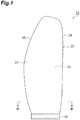
Figure 1 is a front view illustrating a fan rotor blade according to an embodiment of the present disclosure. -
Figure 2 is a side view illustrating the fan rotor blade according to the embodiment of the present disclosure. -
Figure 3 is a top view illustrating the fan rotor blade according to the embodiment of the present disclosure. -
Figure 4 is a cross-sectional view illustrating a cross section taken along line IV-IV ofFigure 1 . -
Figure 5 is a schematic view for describing a method of manufacturing the fan rotor blade according to the embodiment of the present disclosure. -
Figure 6 is a schematic view for describing the fan rotor blade according to the embodiment of the present disclosure. - A fan rotor blade according to an aspect of the present disclosure comprises: an outer covering member made of a composite material including a thermoplastic resin and reinforcing fibers, the outer covering member having a shape of a blade surface having a positive pressure surface and a negative pressure surface; and a metal core body arranged between the positive pressure surface and the negative pressure surface, the metal core body having a hollow structure.
- In this fan rotor blade, the outer covering member made of a composite material has a shape of a blade surface having a positive pressure surface and a negative pressure surface. Therefore, an excellent mechanical strength can be obtained as compared with a case in which the positive pressure surface and the negative pressure surface are made of different members. Further, in this fan rotor blade, the metal core body having a hollow structure is arranged between the positive pressure surface and the negative pressure surface, and the entire weight reduction is achieved by the metal core body. Furthermore, heating is required to mold the composite material including the thermoplastic resin, but in this fan rotor blade, the core body having a hollow structure is made of metal, which prevents deformation due to heating during molding. For this reason, deformation of the blade surface shape, reduction in mechanical strength, and the like due to deformation of the core body are sufficiently prevented.
- In an aspect, the hollow structure may be a structure selected from a honeycomb structure, a lattice structure, and a foam structure. In this case, the pressure resistance of the metal core body is improved. Thus, a higher pressure can be applied when molding the outer covering member and the outer covering member can have a finer blade surface shape.
- In an aspect, a part of the thermoplastic resin constituting the outer covering member may be penetrated into the hollow structure of the metal core body. The method disclosed in Patent Literature 1 has a problem that a bonding strength between the lightweight core material and the preform upper and lower surface bodies cannot be sufficiently secured. In contrast to this, in the present aspect, the thermoplastic resin penetrated into the hollow structure improves the bonding strength between the outer covering member and the metal core body, and thus the fan rotor blade has a more excellent mechanical strength.
- A method of manufacturing a fan rotor blade according to an aspect of the present disclosure comprises: a first molding step of obtaining a preform by laminating and integrating a plurality of composite sheets including a thermoplastic resin and reinforcing fibers; and a second molding step of overlapping a plurality of preforms with a metal core body having a hollow structure, the metal core body being interposed therebetween, and integrating the preforms by heating and pressurizing.
- In this manufacturing method, the outer covering member having a blade surface shape is integrally molded from the preform molded from a composite sheet including a thermoplastic resin and reinforcing fibers. Further, the metal core body is placed inside the outer covering member by overlapping the plurality of preforms with the metal core body interposed therebetween. Therefore, according to the above manufacturing method, the above described fan rotor blade having an excellent mechanical strength can be easily manufactured.
- In an aspect, the hollow structure may be a structure selected from a honeycomb structure, a lattice structure, and a foam structure. In this case, the metal core body has a good pressure resistance, and thus can be pressurized by a higher pressure in the second molding step. Therefore, the fan rotor blade having a finer blade surface shape can be manufactured.
- Hereinafter, a preferred embodiment of the present disclosure will be described with reference to the accompanying drawings. Note that in the description of the drawings, the same reference numerals or characters are assigned to the same components, and the duplicate description is omitted. Note that some drawings are exaggeratedly drawn for ease of understanding, and the dimensional ratios and the like are not limited to those illustrated in the drawings.
-
Figure 1 is a front view illustrating a fan rotor blade according to an embodiment of the present disclosure.Figure 2 is a side view illustrating the fan rotor blade according to the embodiment of the present disclosure.Figure 3 is a top view illustrating the fan rotor blade according to the embodiment of the present disclosure. Further,Figure 4 is a cross-sectional view illustrating a cross section taken along line IV-IV ofFigure 1 . Further,Figure 5 is a schematic view for describing a method of manufacturing the fan rotor blade according to the embodiment of the present disclosure.Figure 6 is a schematic view for describing the fan rotor blade according to the embodiment of the present disclosure. - As illustrated in
Figures 1 to 4 , afan rotor blade 10 according to the present embodiment comprises anouter covering member 20 and ametal core body 30 covered with theouter covering member 20. Further, thefan rotor blade 10 comprises ablade portion 21 having a blade surface shape and asupport portion 22 extending to a blade root end of theblade portion 21. Theblade portion 21 and thesupport portion 22 are integrally molded by the outer coveringmember 20. The blade surface shape of theblade portion 21 is defined by a leadingedge 25, atrailing edge 26, apositive pressure surface 23 which is a side surface on the front side in the rotational direction extending from the leadingedge 25 to thetrailing edge 26, and anegative pressure surface 24 which is a side surface on the rear side in the rotational direction extending from the leadingedge 25 to thetrailing edge 26. In order to fix thefan rotor blade 10 to a support body (unillustrated) such as a fan disk, thesupport portion 22 has a shape to fit in a mounting groove of the support body. - The outer covering
member 20 is made of a composite material including a thermoplastic resin and reinforcing fibers. The type of the thermoplastic resin is not particularly limited, but may be appropriately selected from well-known engineering plastics, super engineering plastics, and the like according to characteristics such as strength and toughness required for thefan rotor blade 10. Preferred examples of the thermoplastic resin include polyether imide (PEI), polyether ether ketone (PEEK), and polyether ketone ketone (PEKK). The composite material may contain one kind of thermoplastic resin or may contain two or more thermoplastic resins. The type of the reinforcing fibers is also not particularly limited, but may be appropriately selected from well-known reinforcing fibers according to characteristics such as strength and toughness required for thefan rotor blade 10. Preferred examples of the reinforcing fibers include carbon fibers, aramid fibers, and glass fibers. - The outer covering
member 20 is formed by further integrally molding thepreforms 41 to 44 formed by laminating and integrating a plurality of composite sheets including a thermoplastic resin and reinforcing fibers to be described later. Examples of the composite sheet may be a composite sheet made of reinforcing fibers impregnated with a thermoplastic resin or reinforcing fibers distributed in a thermoplastic resin. Examples of the composite sheet include a unidirectional prepreg obtained by impregnating a thermoplastic resin into reinforcing fibers aligned in one direction. Further, the composite sheet may be a woven fabric prepreg obtained by impregnating a thermoplastic resin into reinforcing fibers for woven fabrics such as plain weaves, twill weaves, and satin weaves. - The
metal core body 30 has a hollow structure. The hollow structure of themetal core body 30 may be designed in such a way as the weight of themetal core body 30 is smaller than that of an equal volume of composite material. In other words, themetal core body 30 may have a specific gravity smaller than that of the composite material. Examples of the specific gravity of themetal core body 30 may be 0.2 to 1.5, and may be higher than the density of a fiber reinforced plastic (FRP) for reinforcement of rigidity and strength. Further, examples of the porosity of themetal core body 30 may be 5 to 40%, and may be 40% or more and less than 100%. The porosity of 100% corresponds to a case in which the metal core body is removed after manufacturing of the blade. - The
metal core body 30 may have a hollow structure, for example, selected from a honeycomb structure, a lattice structure, and a foam structure. In this case, the pressure resistance of the metal core body is improved. Thus, a higher pressure can be applied when molding the outer covering member and the outer covering member can have a finer blade surface shape. The honeycomb structure is a structure in which solid figures are arranged without a gap, and may have a structure, for example, obtained by arranging regular hexagonal prisms without a gap. The lattice structure is also referred to as a grid structure. Examples of the lattice shape in the lattice structure may include a simple lattice structure (cubic structure), an orthogonal lattice structure, a body-centered cubic lattice structure, a diamond lattice structure, and the like. The lattice spacing and the lattice thickness in the lattice structure may be appropriately changed according to the desired specific gravity. Examples of the lattice spacing in the lattice structure may be 2 to 3 mm, and may be 3 to 10 mm. Examples of the lattice thickness in the lattice structure may be 0.4 to 1.0 mm. The foam structure may be an open cell structure or a closed cell structure. The metal material constituting themetal core body 30 is not particularly limited, and the examples thereof may include a titanium alloy, a nickel alloy, a stainless alloy, and the like. - The
metal core body 30 is disposed on the blade root end of thefan rotor blade 10. Further, in thefan rotor blade 10, themetal core body 30 constitutes a part of an inner structure on the blade root end side of theblade portion 21 and a part of an inner structure of thesupport portion 22. The outer shape of themetal core body 30 may be any shape as long as the mechanical strength of thefan rotor blade 10 is secured by theouter covering member 20. The blade root end side of theblade portion 21 and thesupport portion 22 are relatively thick portions in thefan rotor blade 10, and thus themetal core body 30 disposed in these inner structures can have a larger outer shape. - In an aspect, a part of the thermoplastic resin constituting the
outer covering member 20 may be penetrated into the hollow structure of themetal core body 30. The thermoplastic resin penetrated into the hollow structure of themetal core body 30 is integrated with the composite material of theouter covering member 20, which can improve the bonding strength between themetal core body 30 and the outer covering member by an anchor effect. - In the
fan rotor blade 10, theouter covering member 20 made of a composite material has a shape of a blade surface having thepositive pressure surface 23 and thenegative pressure surface 24. Therefore, an excellent mechanical strength can be obtained as compared with a case in which thepositive pressure surface 23 and thenegative pressure surface 24 are made of different members. Further, in thisfan rotor blade 10, themetal core body 30 having a hollow structure is arranged between thepositive pressure surface 23 and thenegative pressure surface 24, and the entire weight reduction is achieved by themetal core body 30. Furthermore, heating is required to mold the composite material including the thermoplastic resin, but in thisfan rotor blade 10, the core body having a hollow structure is made of metal, which prevents deformation due to heating during molding. For this reason, deformation of the blade surface shape, reduction in mechanical strength, and the like due to deformation of the core body are sufficiently prevented. - Then, the method of manufacturing the
fan rotor blade 10 according to the present embodiment will be described with reference toFigure 5 . - The manufacturing method according to the present embodiment comprises a first molding step of obtaining a preform by laminating and integrating a plurality of composite sheets; and a second molding step of overlapping the plurality of preforms with the
metal core body 30 interposed therebetween and integrating the preforms by heating and pressurizing. - In the first molding step, for example, a
preform 41 is molded by laminating and integrating the composite sheets. Thepreform 41 comprises afirst mold portion 41a for forming theblade portion 21; and asecond mold portion 41b for forming thesupport portion 22 extending to the blade root end of thefirst mold portion 41a. - Examples of the first molding step may be a step of forming the
preform 41 by heating and pressurizing a laminated body obtained by laminating a plurality of composite sheets. The laminated body is formed by laminating a predetermined number of composite sheets each having a predetermined size at a predetermined position corresponding to the thickness and the three-dimensional shape of thepreform 41 to be formed. Then, the laminated body is placed, for example, in a mold and the mold is pressurized at a predetermined pressure while being heated to a predetermined temperature, thereby to form thepreform 41. The heating temperature may be any temperature as long as the temperature allows a plurality of composite sheets to be integrally molded, and, for example, may be a temperature equal to or greater than the softening point of the thermoplastic resin. The pressure for pressurization may be any pressure as long as the pressure allows a plurality of composite sheets to be integrally molded, and, for example may be 1 to 15 MPa. - In the first molding step, the
preforms preforms preform 41. Further, thepreforms first mold portions blade portion 21; and thesecond mold portions support portion 22 respectively in the same manner as thepreform 41. - The
preforms outer covering member 20 of thefan rotor blade 10 is divided into a plurality of pieces in the thickness direction. Further, thepreforms negative pressure surface 24 and thepositive pressure surface 23 of thefan rotor blade 10 respectively. - In the second molding step, the plurality of
preforms metal core body 30 interposed therebetween and by being heated and pressurized. Thepreforms metal core body 30 is interposed between thepreforms - In the second molding step, the
fan rotor blade 10 is formed, for example, by overlapping thepreforms metal core body 30 interposed therebetween, placing them in a mold, and pressurizing the mold at a predetermined pressure while heating the mold to a predetermined temperature. At this time, the thermoplastic resin of each of thepreforms outer covering member 20. Further, theblade portion 21 is formed of thefirst mold portions preforms metal core body 30 interposed therebetween; and the support portion 2 is formed of thesecond mold portions preforms metal core body 30 interposed therebetween. - In the second molding step, the heating temperature may be any temperature as long as the temperature allows the plurality of
preforms preforms - In the second molding step, the heating and pressurizing conditions may be adjusted in such a way as the thermoplastic resin of the
preforms metal core body 30 may be penetrated into the hollow structure of themetal core body 30. Thereby, there is formed a structure in which a part of the thermoplastic resin of theouter covering member 20 penetrates into the hollow structure of themetal core body 30. Note that an increase in heating temperature and pressurizing pressure increases the filling amount of the thermoplastic resin filled into the hollow structure of themetal core body 30. - In the manufacturing method according to the present embodiment, the
outer covering member 20 having a blade surface shape is integrally formed of thepreforms metal core body 30 is placed inside theouter covering member 20 by overlapping the plurality ofpreforms metal core body 30 interposed therebetween. Therefore, the above manufacturing method can easily manufacture thefan rotor blade 10 having an excellent mechanical strength. - Hereinabove, a preferred embodiment of the present disclosure has been described, but the present disclosure is not limited to the above embodiment.
- According to the present disclosure, a fan rotor blade achieving weight reduction while sufficiently securing mechanical strength can be obtained and the fan rotor blade can be suitably used in an aircraft engine and the like.
-
- 10
- fan rotor blade
- 20
- outer covering member
- 21
- blade portion
- 22
- support portion
- 23
- positive pressure surface
- 24
- negative pressure surface
- 25
- leading edge
- 26
- trailing edge
- 30
- metal core body
- 41 to 44
- preform
Claims (6)
- A fan rotor blade comprising:an outer covering member made of a composite material including a thermoplastic resin and reinforcing fibers, the outer covering member having a shape of a blade surface having a positive pressure surface and a negative pressure surface; anda metal core body arranged between the positive pressure surface and the negative pressure surface, the metal core body having a hollow structure.
- The fan rotor blade according to claim 1, wherein the hollow structure is selected from a honeycomb structure, a lattice structure, and a foam structure.
- The fan rotor blade according to claim 1, wherein a part of the thermoplastic resin constituting the outer covering member penetrates into the hollow structure of the metal core body.
- The fan rotor blade according to claim 2, wherein a part of the thermoplastic resin constituting the outer covering member penetrates into the hollow structure of the metal core body.
- A method of manufacturing a fan rotor blade, the method comprising:a first molding step of obtaining a preform by laminating and integrating a plurality of composite sheets including a thermoplastic resin and reinforcing fibers, the preform comprising a plurality of preforms; anda second molding step of overlapping the plurality of preforms with a metal core body having a hollow structure, the metal core body being interposed therebetween, and integrating the preforms by heating and pressurizing.
- The method of manufacturing the fan rotor blade according to claim 5, wherein the hollow structure is selected from a honeycomb structure, a lattice structure, and a foam structure.
Applications Claiming Priority (2)
| Application Number | Priority Date | Filing Date | Title |
|---|---|---|---|
| JP2016204392A JP2018066289A (en) | 2016-10-18 | 2016-10-18 | Fan rotor blade and method for manufacturing the same |
| PCT/JP2017/037393 WO2018074423A1 (en) | 2016-10-18 | 2017-10-16 | Fan rotor blade and method of manufacturing same |
Publications (2)
| Publication Number | Publication Date |
|---|---|
| EP3530958A1 true EP3530958A1 (en) | 2019-08-28 |
| EP3530958A4 EP3530958A4 (en) | 2020-05-20 |
Family
ID=62018650
Family Applications (1)
| Application Number | Title | Priority Date | Filing Date |
|---|---|---|---|
| EP17862837.6A Withdrawn EP3530958A4 (en) | 2016-10-18 | 2017-10-16 | FAN ROTOR VANE AND MANUFACTURING METHOD THEREOF |
Country Status (5)
| Country | Link |
|---|---|
| US (1) | US20190249684A1 (en) |
| EP (1) | EP3530958A4 (en) |
| JP (1) | JP2018066289A (en) |
| CA (1) | CA3040845C (en) |
| WO (1) | WO2018074423A1 (en) |
Families Citing this family (6)
| Publication number | Priority date | Publication date | Assignee | Title |
|---|---|---|---|---|
| US10774653B2 (en) * | 2018-12-11 | 2020-09-15 | Raytheon Technologies Corporation | Composite gas turbine engine component with lattice structure |
| CN109372798A (en) * | 2018-12-13 | 2019-02-22 | 中国航发沈阳发动机研究所 | A kind of fan blade |
| CN109989938B (en) * | 2019-03-22 | 2024-02-06 | 中国科学院工程热物理研究所 | Fan blade of aeroengine and manufacturing method thereof |
| JP7411462B2 (en) * | 2020-03-17 | 2024-01-11 | 三菱重工業株式会社 | Composite wing, rotating machine, and method for forming composite wing |
| US12391010B2 (en) | 2023-01-13 | 2025-08-19 | Rtx Corporation | Methods of manufacture for composite blades |
| US12442305B2 (en) | 2023-06-01 | 2025-10-14 | General Electric Company | Composite airfoil assembly for a turbine engine |
Family Cites Families (11)
| Publication number | Priority date | Publication date | Assignee | Title |
|---|---|---|---|---|
| CA2042218A1 (en) * | 1990-07-20 | 1992-01-21 | Jan C. Schilling | Composite airfoil with increased shear capability |
| JPH04316845A (en) * | 1991-04-16 | 1992-11-09 | Mitsubishi Heavy Ind Ltd | Method for molding composite material blade shape |
| JP3280754B2 (en) | 1993-06-15 | 2002-05-13 | 三菱樹脂株式会社 | Manufacturing method of fiber reinforced plastic blower blade |
| US5720597A (en) * | 1996-01-29 | 1998-02-24 | General Electric Company | Multi-component blade for a gas turbine |
| JP2000356198A (en) * | 1999-06-11 | 2000-12-26 | Mitsubishi Heavy Ind Ltd | Moving blade for axial flow blower |
| JP4748852B2 (en) * | 2000-12-12 | 2011-08-17 | 臼井国際産業株式会社 | Fan with resin blade |
| US7736130B2 (en) * | 2007-07-23 | 2010-06-15 | General Electric Company | Airfoil and method for protecting airfoil leading edge |
| EP2479217B1 (en) * | 2009-09-16 | 2019-08-28 | Toray Industries, Inc. | Binder composition, reinforcing-fiber base material, preform, fiber-reinforced composite material, and manufacturing method therefor |
| US9004873B2 (en) * | 2010-12-27 | 2015-04-14 | Rolls-Royce Corporation | Airfoil, turbomachine and gas turbine engine |
| EP2896789B1 (en) * | 2014-01-16 | 2018-03-07 | United Technologies Corporation | Fan blade with variable thickness composite cover |
| US10035174B2 (en) * | 2015-02-09 | 2018-07-31 | United Technologies Corporation | Open-cell reticulated foam |
-
2016
- 2016-10-18 JP JP2016204392A patent/JP2018066289A/en active Pending
-
2017
- 2017-10-16 US US16/342,016 patent/US20190249684A1/en not_active Abandoned
- 2017-10-16 WO PCT/JP2017/037393 patent/WO2018074423A1/en not_active Ceased
- 2017-10-16 EP EP17862837.6A patent/EP3530958A4/en not_active Withdrawn
- 2017-10-16 CA CA3040845A patent/CA3040845C/en not_active Expired - Fee Related
Also Published As
| Publication number | Publication date |
|---|---|
| CA3040845C (en) | 2021-03-23 |
| EP3530958A4 (en) | 2020-05-20 |
| JP2018066289A (en) | 2018-04-26 |
| WO2018074423A1 (en) | 2018-04-26 |
| CA3040845A1 (en) | 2018-04-26 |
| US20190249684A1 (en) | 2019-08-15 |
Similar Documents
| Publication | Publication Date | Title |
|---|---|---|
| CA3040845C (en) | Fan rotor blade and method of manufacturing same | |
| JP5922032B2 (en) | Aircraft propeller blades | |
| CN101021202B (en) | Carbon-glass hybrid spars for wind turbine rotor blades | |
| EP2326488B1 (en) | A method of manufacturing a wind turbine blade shell part comprising a magnetisable material | |
| EP2388477B1 (en) | Blade of a wind turbine | |
| EP2113373B1 (en) | Method for manufacturing of a fibre reinforced laminate and of a laterally extended material which has in a first lateral direction a greater stiffness than in a second lateral direction | |
| EP2170587B1 (en) | A method of manufacturing a curved element made of composite material | |
| EP3147108B1 (en) | Carbon fiber composite material | |
| EP2933094B1 (en) | Method of forming radius fillers for composite structures | |
| CN109562578B (en) | Composite structure and method of manufacturing composite structure | |
| EP2543499A1 (en) | Wind turbine blade comprising metal filaments and carbon fibres and a method of manufacturing thereof | |
| US20170204833A1 (en) | Rotor Blades Having Structural Skin Insert and Methods of Making Same | |
| US20160032939A1 (en) | Airfoil structures | |
| BR112016017533B1 (en) | part of wind turbine blade manufactured in two stages | |
| CN103261499A (en) | Fibrous structure for a part made of composite material having one or more arch-shaped portions | |
| CN104245295B (en) | With the hat reinforcement for tilting web and the method for forming hat reinforcement | |
| US9382647B2 (en) | Fibrous structure for a part made of a composite material and having a complex shape | |
| EP3406434B1 (en) | Composite blade and method of manufacture | |
| WO2013104056A1 (en) | Woven fabric preforms and process for making the same | |
| JP2003071864A (en) | Manufacturing method of composite reinforcing plate | |
| CN117355414A (en) | Laminated body for pressing and laminate after pressing | |
| US20210316526A1 (en) | Fiber-reinforced composite blank, fiber-reinforced composite component, rotor blade element, rotor blade and wind turbine and method for producing a fiber-reinforced composite blank and method for producing a fiber-reinforced composite component | |
| CN110356013A (en) | The connection of propeller blade root | |
| EP3663196A1 (en) | Landing gear for rotary-wing aircraft | |
| CN116997457B (en) | Flat lightweight component and method for manufacturing same |
Legal Events
| Date | Code | Title | Description |
|---|---|---|---|
| STAA | Information on the status of an ep patent application or granted ep patent |
Free format text: STATUS: THE INTERNATIONAL PUBLICATION HAS BEEN MADE |
|
| PUAI | Public reference made under article 153(3) epc to a published international application that has entered the european phase |
Free format text: ORIGINAL CODE: 0009012 |
|
| STAA | Information on the status of an ep patent application or granted ep patent |
Free format text: STATUS: REQUEST FOR EXAMINATION WAS MADE |
|
| 17P | Request for examination filed |
Effective date: 20190520 |
|
| AK | Designated contracting states |
Kind code of ref document: A1 Designated state(s): AL AT BE BG CH CY CZ DE DK EE ES FI FR GB GR HR HU IE IS IT LI LT LU LV MC MK MT NL NO PL PT RO RS SE SI SK SM TR |
|
| A4 | Supplementary search report drawn up and despatched |
Effective date: 20200422 |
|
| RIC1 | Information provided on ipc code assigned before grant |
Ipc: F04D 29/38 20060101AFI20200416BHEP Ipc: F04D 29/02 20060101ALI20200416BHEP |
|
| STAA | Information on the status of an ep patent application or granted ep patent |
Free format text: STATUS: THE APPLICATION HAS BEEN WITHDRAWN |
|
| 18W | Application withdrawn |
Effective date: 20210818 |