EP3530952A1 - Vacuum pump, waterproof structure applied to vacuum pump, and control device - Google Patents
Vacuum pump, waterproof structure applied to vacuum pump, and control device Download PDFInfo
- Publication number
- EP3530952A1 EP3530952A1 EP17861978.9A EP17861978A EP3530952A1 EP 3530952 A1 EP3530952 A1 EP 3530952A1 EP 17861978 A EP17861978 A EP 17861978A EP 3530952 A1 EP3530952 A1 EP 3530952A1
- Authority
- EP
- European Patent Office
- Prior art keywords
- control apparatus
- vacuum pump
- base portion
- gap
- wall portion
- Prior art date
- Legal status (The legal status is an assumption and is not a legal conclusion. Google has not performed a legal analysis and makes no representation as to the accuracy of the status listed.)
- Granted
Links
Images


Classifications
-
- F—MECHANICAL ENGINEERING; LIGHTING; HEATING; WEAPONS; BLASTING
- F04—POSITIVE - DISPLACEMENT MACHINES FOR LIQUIDS; PUMPS FOR LIQUIDS OR ELASTIC FLUIDS
- F04D—NON-POSITIVE-DISPLACEMENT PUMPS
- F04D25/00—Pumping installations or systems
- F04D25/02—Units comprising pumps and their driving means
- F04D25/06—Units comprising pumps and their driving means the pump being electrically driven
- F04D25/068—Mechanical details of the pump control unit
-
- F—MECHANICAL ENGINEERING; LIGHTING; HEATING; WEAPONS; BLASTING
- F04—POSITIVE - DISPLACEMENT MACHINES FOR LIQUIDS; PUMPS FOR LIQUIDS OR ELASTIC FLUIDS
- F04D—NON-POSITIVE-DISPLACEMENT PUMPS
- F04D19/00—Axial-flow pumps
- F04D19/02—Multi-stage pumps
- F04D19/04—Multi-stage pumps specially adapted to the production of a high vacuum, e.g. molecular pumps
- F04D19/042—Turbomolecular vacuum pumps
-
- F—MECHANICAL ENGINEERING; LIGHTING; HEATING; WEAPONS; BLASTING
- F04—POSITIVE - DISPLACEMENT MACHINES FOR LIQUIDS; PUMPS FOR LIQUIDS OR ELASTIC FLUIDS
- F04B—POSITIVE-DISPLACEMENT MACHINES FOR LIQUIDS; PUMPS
- F04B37/00—Pumps having pertinent characteristics not provided for in, or of interest apart from, groups F04B25/00 - F04B35/00
- F04B37/10—Pumps having pertinent characteristics not provided for in, or of interest apart from, groups F04B25/00 - F04B35/00 for special use
- F04B37/14—Pumps having pertinent characteristics not provided for in, or of interest apart from, groups F04B25/00 - F04B35/00 for special use to obtain high vacuum
-
- F—MECHANICAL ENGINEERING; LIGHTING; HEATING; WEAPONS; BLASTING
- F04—POSITIVE - DISPLACEMENT MACHINES FOR LIQUIDS; PUMPS FOR LIQUIDS OR ELASTIC FLUIDS
- F04B—POSITIVE-DISPLACEMENT MACHINES FOR LIQUIDS; PUMPS
- F04B37/00—Pumps having pertinent characteristics not provided for in, or of interest apart from, groups F04B25/00 - F04B35/00
- F04B37/10—Pumps having pertinent characteristics not provided for in, or of interest apart from, groups F04B25/00 - F04B35/00 for special use
- F04B37/14—Pumps having pertinent characteristics not provided for in, or of interest apart from, groups F04B25/00 - F04B35/00 for special use to obtain high vacuum
- F04B37/16—Means for nullifying unswept space
-
- F—MECHANICAL ENGINEERING; LIGHTING; HEATING; WEAPONS; BLASTING
- F04—POSITIVE - DISPLACEMENT MACHINES FOR LIQUIDS; PUMPS FOR LIQUIDS OR ELASTIC FLUIDS
- F04B—POSITIVE-DISPLACEMENT MACHINES FOR LIQUIDS; PUMPS
- F04B39/00—Component parts, details, or accessories, of pumps or pumping systems specially adapted for elastic fluids, not otherwise provided for in, or of interest apart from, groups F04B25/00 - F04B37/00
-
- F—MECHANICAL ENGINEERING; LIGHTING; HEATING; WEAPONS; BLASTING
- F04—POSITIVE - DISPLACEMENT MACHINES FOR LIQUIDS; PUMPS FOR LIQUIDS OR ELASTIC FLUIDS
- F04D—NON-POSITIVE-DISPLACEMENT PUMPS
- F04D17/00—Radial-flow pumps, e.g. centrifugal pumps; Helico-centrifugal pumps
- F04D17/08—Centrifugal pumps
- F04D17/16—Centrifugal pumps for displacing without appreciable compression
- F04D17/168—Pumps specially adapted to produce a vacuum
-
- F—MECHANICAL ENGINEERING; LIGHTING; HEATING; WEAPONS; BLASTING
- F04—POSITIVE - DISPLACEMENT MACHINES FOR LIQUIDS; PUMPS FOR LIQUIDS OR ELASTIC FLUIDS
- F04D—NON-POSITIVE-DISPLACEMENT PUMPS
- F04D19/00—Axial-flow pumps
- F04D19/02—Multi-stage pumps
- F04D19/04—Multi-stage pumps specially adapted to the production of a high vacuum, e.g. molecular pumps
-
- F—MECHANICAL ENGINEERING; LIGHTING; HEATING; WEAPONS; BLASTING
- F04—POSITIVE - DISPLACEMENT MACHINES FOR LIQUIDS; PUMPS FOR LIQUIDS OR ELASTIC FLUIDS
- F04D—NON-POSITIVE-DISPLACEMENT PUMPS
- F04D25/00—Pumping installations or systems
- F04D25/02—Units comprising pumps and their driving means
- F04D25/06—Units comprising pumps and their driving means the pump being electrically driven
- F04D25/0693—Details or arrangements of the wiring
-
- F—MECHANICAL ENGINEERING; LIGHTING; HEATING; WEAPONS; BLASTING
- F04—POSITIVE - DISPLACEMENT MACHINES FOR LIQUIDS; PUMPS FOR LIQUIDS OR ELASTIC FLUIDS
- F04D—NON-POSITIVE-DISPLACEMENT PUMPS
- F04D29/00—Details, component parts, or accessories
- F04D29/08—Sealings
- F04D29/083—Sealings especially adapted for elastic fluid pumps
-
- F—MECHANICAL ENGINEERING; LIGHTING; HEATING; WEAPONS; BLASTING
- F04—POSITIVE - DISPLACEMENT MACHINES FOR LIQUIDS; PUMPS FOR LIQUIDS OR ELASTIC FLUIDS
- F04D—NON-POSITIVE-DISPLACEMENT PUMPS
- F04D29/00—Details, component parts, or accessories
- F04D29/40—Casings; Connections of working fluid
- F04D29/52—Casings; Connections of working fluid for axial pumps
- F04D29/522—Casings; Connections of working fluid for axial pumps especially adapted for elastic fluid pumps
-
- H—ELECTRICITY
- H01—ELECTRIC ELEMENTS
- H01R—ELECTRICALLY-CONDUCTIVE CONNECTIONS; STRUCTURAL ASSOCIATIONS OF A PLURALITY OF MUTUALLY-INSULATED ELECTRICAL CONNECTING ELEMENTS; COUPLING DEVICES; CURRENT COLLECTORS
- H01R13/00—Details of coupling devices of the kinds covered by groups H01R12/70 or H01R24/00 - H01R33/00
- H01R13/46—Bases; Cases
- H01R13/52—Dustproof, splashproof, drip-proof, waterproof, or flameproof cases
-
- F—MECHANICAL ENGINEERING; LIGHTING; HEATING; WEAPONS; BLASTING
- F04—POSITIVE - DISPLACEMENT MACHINES FOR LIQUIDS; PUMPS FOR LIQUIDS OR ELASTIC FLUIDS
- F04D—NON-POSITIVE-DISPLACEMENT PUMPS
- F04D19/00—Axial-flow pumps
- F04D19/02—Multi-stage pumps
- F04D19/04—Multi-stage pumps specially adapted to the production of a high vacuum, e.g. molecular pumps
- F04D19/048—Multi-stage pumps specially adapted to the production of a high vacuum, e.g. molecular pumps comprising magnetic bearings
-
- F—MECHANICAL ENGINEERING; LIGHTING; HEATING; WEAPONS; BLASTING
- F04—POSITIVE - DISPLACEMENT MACHINES FOR LIQUIDS; PUMPS FOR LIQUIDS OR ELASTIC FLUIDS
- F04D—NON-POSITIVE-DISPLACEMENT PUMPS
- F04D29/00—Details, component parts, or accessories
- F04D29/58—Cooling; Heating; Diminishing heat transfer
- F04D29/582—Cooling; Heating; Diminishing heat transfer specially adapted for elastic fluid pumps
- F04D29/5853—Cooling; Heating; Diminishing heat transfer specially adapted for elastic fluid pumps heat insulation or conduction
-
- F—MECHANICAL ENGINEERING; LIGHTING; HEATING; WEAPONS; BLASTING
- F05—INDEXING SCHEMES RELATING TO ENGINES OR PUMPS IN VARIOUS SUBCLASSES OF CLASSES F01-F04
- F05D—INDEXING SCHEME FOR ASPECTS RELATING TO NON-POSITIVE-DISPLACEMENT MACHINES OR ENGINES, GAS-TURBINES OR JET-PROPULSION PLANTS
- F05D2210/00—Working fluids
- F05D2210/10—Kind or type
- F05D2210/12—Kind or type gaseous, i.e. compressible
-
- F—MECHANICAL ENGINEERING; LIGHTING; HEATING; WEAPONS; BLASTING
- F05—INDEXING SCHEMES RELATING TO ENGINES OR PUMPS IN VARIOUS SUBCLASSES OF CLASSES F01-F04
- F05D—INDEXING SCHEME FOR ASPECTS RELATING TO NON-POSITIVE-DISPLACEMENT MACHINES OR ENGINES, GAS-TURBINES OR JET-PROPULSION PLANTS
- F05D2240/00—Components
- F05D2240/55—Seals
Definitions
- aligning positions of a terminal on the side of the pump main body and a terminal on the side of the control apparatus requires that a worker check whether the terminals are attached or detached while looking at locations of the terminals through an extremely narrow gap between the pump main body and the control apparatus, thereby making alignment of positions and maintenance work difficult.
- the present invention provides a vacuum pump in which a control apparatus is detachably arranged with respect to a base portion of a pump main body and which includes a waterproof structure, wherein the waterproof structure includes: a connector portion which is arranged in a side portion of the base portion and which connects the base portion with the control apparatus via an electric cable; a wall portion which is protrusively provided around the connector portion so as to expand from the base portion to the control apparatus; and a wall portion cover which covers the wall portion.
- the gap cover portion may be integrally configured with respect to the cover or may be configured as a separate body.
- the present invention is an invention of a vacuum pump, the vacuum pump including: a gap formed between the base portion and the control apparatus; and a bent part formed by bending an end of an upper surface of the control apparatus toward a side of the base portion of the pump main body, wherein an outer periphery of the gap is covered by the bent part.
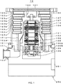
- FIG. 1 shows a configuration diagram of the first embodiment of the present invention.
- a pump main body 100 and a control apparatus 200 are integrated with each other.
- a rotor blade 102d is suspended from a lowermost portion which continues from the rotor blades 102a, 102b, 102c, ... of the rotating body 103.
- An outer peripheral surface of the rotor blade 102d is cylindrical in shape and overhangs toward the inner circumferential surface of the threaded spacer 131, and is in proximity to the inner circumferential surface of the threaded spacer 131 across a prescribed gap.
- a metal having both rigidity and high thermal conductivity such as iron, aluminum, or copper is desirably used.
- the wall portion cover 201 is formed in a curved surface shape so as to conform to outer shapes of the base portion 129 and the control apparatus 200.
- the wall portion cover 201 is desirably formed in a flat surface shape or the like so as to conform to the shape of the pump.
- the wall portion cover 201 is formed so as to have a short peripheral length on a side of the base portion 129 and a long peripheral length on a side of the control apparatus 200 in accordance with routing of wiring.
- FIG. 7 a configuration shown in FIG. 7 may be adopted in place of the gap cover portion 201a shown in FIG. 2 .
- the right end of the lid 217 is bent in an L-shape up to a range which covers the thickness of the sealing member 219 to form a bent part 217a. Even in this case, in a similar manner to that described above, water droplets cannot easily penetrate into the gap 210. Accordingly, safety of circuits during maintenance work can be ensured.
- the wall portion 222 may have a shape other than a triangle such as a square or a circle as long the wall portion 222 is structured so that the water droplet 225 flows along the groove 223.
Landscapes
- Engineering & Computer Science (AREA)
- Mechanical Engineering (AREA)
- General Engineering & Computer Science (AREA)
- Non-Positive Displacement Air Blowers (AREA)
- Compressor (AREA)
- Compressors, Vaccum Pumps And Other Relevant Systems (AREA)
- Structures Of Non-Positive Displacement Pumps (AREA)
Abstract
Description
- The present invention relates to a vacuum pump, and a waterproof structure and a control apparatus applied to the vacuum pump and, in particular, to a vacuum pump, and a waterproof structure and a control apparatus applied to the vacuum pump which improve efficiency of on-site maintenance work and, at the same time, prevent water from penetrating into a connector connecting portion when a cover is removed during circuit separation or the like.
- With recent developments in electronics, there is a rapidly growing demand for semiconductors such as memories and integrated circuits.
- These semiconductors are manufactured by doping an extremely pure semiconductor substrate with an impurity to impart an electric property to the semiconductor substrate, forming a minute circuit on the semiconductor substrate by etching, or the like.
- Such operations must be performed inside a chamber in a high-vacuum state in order to circumvent the effect of airborne dust and the like. While vacuum pumps are generally used to exhaust the chamber, in particular, a turbo-molecular pump which is one of such vacuum pumps is frequently used from the perspectives of a small amount of residual gas and easy maintenance.
- In addition, a semiconductor manufacturing process includes a large number of steps in which various process gases are caused to act on a substrate of a semiconductor, and a turbo-molecular pump is used not only to vacuumize the inside of a chamber but also to exhaust such process gases from the chamber.
- The turbo-molecular pump is constituted by a pump main body and a control apparatus which controls the pump main body.
- The pump main body and the control apparatus are usually connected to each other by cables and a connector plug mechanism. In order to avoid hassle due to connection errors and length adjustment of the cables between the pump main body and the control apparatus, structures which make the pump main body and the control apparatus attachable and detachable in an axial direction of a pump are known as disclosed in Japanese Patent Application Laid-open No.
H11-173293 - Generally, empty space around the pump main body and the control apparatus which are integrated as described above is limited. In particular, there is often hardly any available space in the axial direction. Therefore, maintenance must be performed after temporarily detaching the integrated pump main body and the control apparatus from the chamber and moving the still-integrated pump main body and the control apparatus to a location that affords sufficient working space.
- In addition, when terminals are arranged in the axial direction in a bottom portion of the pump main body, aligning positions of a terminal on the side of the pump main body and a terminal on the side of the control apparatus requires that a worker check whether the terminals are attached or detached while looking at locations of the terminals through an extremely narrow gap between the pump main body and the control apparatus, thereby making alignment of positions and maintenance work difficult.
- Furthermore, a water-cooled tube (to be described later) is arranged in the pump main body. Cooling of the pump main body by the water-cooled tube may cause water droplets such as condensation to form around the pump main body. When separating the pump main body and the control apparatus, there is a risk that the water droplets may penetrate into the connector connecting portion from around the pump main body.
- The present invention has been made in consideration of such conventional problems, and an object thereof is to provide a vacuum pump, and a waterproof structure and a control apparatus applied to the vacuum pump which improve efficiency of on-site maintenance work and, at the same time, prevent water from penetrating into a connector connecting portion when a cover is removed during circuit separation or the like.
- To this end, the present invention (claim 1) provides a vacuum pump in which a control apparatus is detachably arranged with respect to a base portion of a pump main body and which includes a waterproof structure, wherein the waterproof structure includes: a connector portion which is arranged in a side portion of the base portion and which connects the base portion with the control apparatus via an electric cable; a wall portion which is protrusively provided around the connector portion so as to expand from the base portion to the control apparatus; and a wall portion cover which covers the wall portion.
- Since the connector is arranged in the side portion of the base portion, the pump main body and the control apparatus can be readily attached and detached even when sufficient empty space is not available in an axial direction of the pump. The wall portion is circumferentially protrusively provided in side portions of the base portion and the control apparatus so as to expand from the base portion to the control apparatus. Therefore, even when a cover is removed during maintenance work, penetration of water droplets can be prevented by the wall portion. Accordingly, safety of circuits during maintenance work can be ensured.
- In addition, the present invention (claim 2) is an invention of a vacuum pump, the vacuum pump including a gap formed between the base portion and the control apparatus, wherein a gap cover portion which covers an outer periphery of the gap is arranged inside the wall portion cover.
- Accordingly, infiltration of water droplets that flow along the gap can be more rigidly prevented. As a result, safety of circuits during maintenance work can be more reliably ensured. The gap cover portion may be integrally configured with respect to the cover or may be configured as a separate body.
- Furthermore, the present invention (claim 3) is an invention of a vacuum pump, the vacuum pump including a gap formed between the base portion and the control apparatus, wherein an outer periphery of the gap is covered by protrusively providing an outer peripheral surface of the control apparatus on a side of the base portion of the pump main body.
- An outer peripheral surface that forms the control apparatus is protrusively provided in the axial direction of the pump. Covering the outer periphery of the gap with the protrusive portion makes it more difficult for water droplets to penetrate into the gap. As a result, safety of circuits during maintenance work can be even more reliably ensured.
- In addition, the present invention (claim 4) is an invention of a vacuum pump, the vacuum pump including: a gap formed between the base portion and the control apparatus; and a bent part formed by bending an end of an upper surface of the control apparatus toward a side of the base portion of the pump main body, wherein an outer periphery of the gap is covered by the bent part.
- A bent part is formed by bending an end of an upper surface of the control apparatus. Covering the outer periphery of the gap with the bent part makes it more difficult for water droplets to penetrate into the gap. As a result, safety of circuits during maintenance work can be even more reliably ensured.
- Furthermore, the present invention (claim 5) is an invention of a vacuum pump, wherein a sealing member for preventing infiltration of water into the gap is arranged with respect to the gap.
- Inserting the sealing member into the gap makes it difficult for water droplets to penetrate into the gap.
- In addition, the present invention (claim 6) is an invention of a vacuum pump, wherein a groove or a hole for draining water is formed in the wall portion or on the upper surface of the control apparatus.
- By forming a groove or a hole through which water droplets pass in the wall portion, since water droplets flow along the groove or the hole even when the cover is removed, water droplets do not penetrate inside. Accordingly, safety of circuits during maintenance work can be ensured.
- Furthermore, the present invention (claim 7) is an invention of a vacuum pump, wherein the wall portion cover is formed so as to conform to outer shapes of the base portion and the control apparatus.
- Accordingly, distracting protrusions around the pump are eliminated to make maintenance work easier and to also improve aesthetics.
- In addition, the present invention (claim 8) is an invention of a waterproof structure, wherein the waterproof structure is arranged in the vacuum pump according to any one of
claims 1 to 7. - Although the vacuum pump includes a large number of cables and tends to be bulky, mounting the waterproof structure enables maintenance work to be easily performed from the side of the pump.
- Furthermore, the present invention (claim 9) is an invention of a control apparatus, wherein the control apparatus is applied to the vacuum pump according to any one of
claims 1 to 7 and is attachable and detachable with respect to the pump main body by moving in a radial direction. - Configuring the control apparatus so as to be movable in the radial direction enables maintenance work to be easily performed even at a location where a sufficient working space cannot be secured in the axial direction of the pump.
- As described above, according to the present invention (claim 1), since the connector is arranged in the side portion of the base portion and the wall portion is formed around the connector so as to expand from the base portion to the control apparatus, the pump main body and the control apparatus can be readily attached and detached even when sufficient empty space is not available in the axial direction of the pump.
- In addition, even when the cover is removed during maintenance work, infiltration of water droplets can be prevented by the wall portion. Accordingly, safety of circuits during maintenance work can be ensured.
-
-
FIG. 1 is a configuration diagram of a first embodiment of the present invention; -
FIG. 2 is a vertical sectional view around a base portion and a control apparatus; -
FIG. 3 is a front view of a base portion and a control apparatus including a cover; -
FIG. 4 is a horizontal sectional view taken along a sagittal line A-A inFIG. 3 ; -
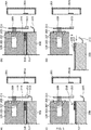
FIGS. 5A to 5D are diagrams showing a procedure when performing maintenance work; -
FIG. 6 is a vertical sectional view (alternate aspect) around a base portion and a control apparatus; -
FIG. 7 is a vertical sectional view (alternate aspect) around a base portion and a control apparatus; -
FIGS. 8A and 8B are configuration diagrams of a second embodiment of the present invention; and -
FIGS. 9A and 9B are diagrams showing an alternate aspect of the second embodiment. - Hereinafter, a first embodiment of the present invention will be described.
FIG. 1 shows a configuration diagram of the first embodiment of the present invention. InFIG. 1 , in a turbo-molecular pump 10, a pumpmain body 100 and acontrol apparatus 200 are integrated with each other. - An
inlet port 101 is formed at an upper end of a cylindricalouter casing 127 of the pumpmain body 100. Arotating body 103 in which a plurality of rotor blades 102a, 102b, 102c, ... constituted by turbine blades for sucking and exhausting gas are radially formed in multiple stages in a peripheral portion inside theouter casing 127. - A rotor shaft 113 is mounted to a center of the
rotating body 103 and, for example, a so-called five-axis control magnetic bearing levitates and supports the rotor shaft 113 in midair and controls a position of the rotor shaft 113. - As an upper
radial electromagnet 104, four electromagnets are arranged so as to form pairs with respect to mutually orthogonal X and Y axes which are coordinate axes in a radial direction of the rotor shaft 113. An upperradial sensor 107 constituted by four electromagnets is provided in proximity to and in correspondence with the upperradial electromagnet 104. The upperradial sensor 107 is configured so as to detect a radial displacement of therotating body 103 and to send the detected radial displacement to thecontrol apparatus 200. - In the
control apparatus 200, based on a displacement signal detected by the upperradial sensor 107, excitation of the upperradial electromagnet 104 is controlled via a compensation circuit having a PID adjustment function and a position in the radial direction of an upper side of the rotor shaft 113 is adjusted. - The rotor shaft 113 is formed of a high magnetic permeability material (such as iron) or the like and is configured so as to be sucked by a magnetic force of the upper
radial electromagnet 104. The adjustment described above is respectively independently performed in an X axis direction and a Y axis direction. - In addition, a lower
radial electromagnet 105 and a lowerradial sensor 108 are arranged in a similar manner to the upperradial electromagnet 104 and the upperradial sensor 107 and adjust a position in the radial direction of a lower side of the rotor shaft 113 in a similar manner to the position in the radial direction of the upper side. - Furthermore, axial electromagnets 106A and 106B are arranged so as to vertically sandwich a disc-shaped
metal disk 111 provided in a lower portion of the rotor shaft 113. Themetal disk 111 is constituted by a high magnetic permeability material such as iron. Anaxial sensor 109 is provided in order to detect an axial displacement of the rotor shaft 113, and theaxial sensor 109 is configured so that an axial displacement signal thereof is sent to thecontrol apparatus 200. - In addition, the axial electromagnets 106A and 106B are configured so that excitation thereof is controlled based on the axial displacement signal via the compensation circuit having a PID adjustment function of the
control apparatus 200. The axial electromagnet 106A and the axial electromagnet 106B respectively suck themetal disk 111 upward and downward by magnetic force. - As described above, the
control apparatus 200 is configured so as to appropriately adjust magnetic forces exerted on themetal disk 111 by the axial electromagnets 106A and 106B in order to magnetically levitate the rotor shaft 113 in the axial direction and hold the rotor shaft 113 in space in a contactless manner. - A
motor 121 includes a plurality of magnetic poles circumferentially arranged so as to surround the rotor shaft 113. Each magnetic pole is controlled by thecontrol apparatus 200 so as to rotationally drive the rotor shaft 113 via an electromagnetic force which acts between the magnetic pole and the rotor shaft 113. - A plurality of stator blades 123a, 123b, 123c, ... are arranged across small gaps from the rotor blades 102a, 102b, 102c, .... The rotor blades 102a, 102b, 102c, ... are formed inclined by a prescribed angle relative to a plane perpendicular to an axial line of the rotor shaft 113 in order to respectively transport a molecule of exhaust gas downward when the exhaust gas collides.
- In addition, the
stator blade 123 is also formed inclined by a prescribed angle relative to a plane perpendicular to the axial line of the rotor shaft 113 and is arranged so as to alternate with the stages of therotor blade 102 toward inside of theouter casing 127. - Furthermore, an end of the
stator blade 123 is supported in a state of being fitted and inserted between a plurality of stacked stator blade spacers 125a, 125b, 125c, .... - The
stator blade spacer 125 is a ring-shaped member constituted by, for example, a metal such as aluminum, iron, stainless steel, or copper or a metal such as an alloy containing these metals as components. - The
outer casing 127 is fixed across a small gap in an outer periphery of thestator blade spacer 125. Abase portion 129 is arranged in a bottom portion of theouter casing 127, and a threaded spacer 131 is arranged between a lower portion of thestator blade spacer 125 and thebase portion 129. In addition, anoutlet port 133 which communicates with outside is formed in a lower portion of the threaded spacer 131 in thebase portion 129. - The threaded spacer 131 is a cylindrical member constituted by a metal such as aluminum, copper, stainless steel, or iron or a metal such as an alloy containing these metals as components, and a spiral thread groove 131a is engraved in plurality on an inner circumferential surface of the threaded spacer 131.
- A direction of the spirals of the thread grooves 131a is a direction in which, when a molecule of exhaust gas moves in a direction of rotation of the
rotating body 103, the molecule is transported toward theoutlet port 133. - A rotor blade 102d is suspended from a lowermost portion which continues from the rotor blades 102a, 102b, 102c, ... of the
rotating body 103. An outer peripheral surface of the rotor blade 102d is cylindrical in shape and overhangs toward the inner circumferential surface of the threaded spacer 131, and is in proximity to the inner circumferential surface of the threaded spacer 131 across a prescribed gap. - The
base portion 129 is a disc-shaped member constituting a base of the turbo-molecular pump 10 and is generally constituted by a metal such as iron, aluminum, or stainless steel. - Since the
base portion 129 physically holds the turbo-molecular pump 10 and also has a function of a heat conductive path, a metal having both rigidity and high thermal conductivity such as iron, aluminum, or copper is desirably used. - In the configuration described above, when the
rotor blade 102 is driven by themotor 121 and rotates together with the rotor shaft 113, exhaust gas from the chamber is sucked through theinlet port 101 due to actions of therotor blade 102 and thestator blade 123. - The exhaust gas sucked from the
inlet port 101 passes between therotor blade 102 and thestator blade 123 and is transported to thebase portion 129. At this point, while a temperature of therotor blade 102 rises due to frictional heat generated when the exhaust gas comes into contact or collides with therotor blade 102, conduction or radiation of heat generated in themotor 121, or the like, this heat is transferred to the side of thestator blade 123 by radiation, conduction by a gas molecule of the exhaust gas, or the like. - The
stator blade spacers 125 are joined to one another in an outer peripheral portion and transfer, to theouter casing 127 and the threaded spacer 131, heat received by thestator blade 123 from therotor blade 102, frictional heat generated when the exhaust gas comes into contact or collides with thestator blade 123, and the like. - The exhaust gas transported to the threaded spacer 131 is sent to the
outlet port 133 while being guided by the thread grooves 131a. - In some cases, process gases are introduced in a high-temperature state into a chamber in order to enhance reactivity. In addition, once the process gases are cooled and drop to a certain temperature when exhausted, the process gases may solidify and cause a product to be deposited in an exhaust system.
- Furthermore, a process gas of this type may cool and solidify inside the turbo-
molecular pump 10 and adhere to and accumulate on the interior of the turbo-molecular pump 10. - When a deposit of a process gas accumulates inside the turbo-
molecular pump 10, the deposit may narrow a pump flow path and cause a decline in performance of the turbo-molecular pump 10. - When a temperature near the outlet port is low, the product described above readily solidifies and adheres particularly near the rotor blade 102d and the threaded spacer 131. In order to solve this problem, conventionally, a heater or an annular water-cooled tube (not shown) is wound around an outer periphery of the
base portion 129 or the like and, for example, a temperature sensor (such as a thermistor) (not shown) is embedded in thebase portion 129, whereby heating by the heater or cooling by the water-cooled tube is controlled so as to keep the temperature of thebase portion 129 at a constant high temperature (set temperature) based on a signal from the temperature sensor. - Next, a structure around terminals to which a control cable and a power cable are connected between the pump
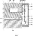
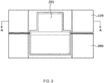
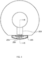
main body 100 and thecontrol apparatus 200 will be described. InFIG. 2 , awall portion 202 is circumferentially protrusively provided in side portions of thebase portion 129 and thecontrol apparatus 200. In addition, awall portion cover 201 is attachably and detachably provided so as to cover and fit with thewall portion 202.FIG. 3 shows a front view of thebase portion 129 and thecontrol apparatus 200 including thewall portion cover 201 andFIG. 4 shows a horizontal sectional view taken along a sagittal line A-A inFIG. 3 . Furthermore,FIG. 2 shows a vertical sectional view around thebase portion 129 and thecontrol apparatus 200 taken along a sagittal line B-B inFIG. 4 . - A
space 203 for a magnetic bearing, wiring of a motor, and the like inside the pumpmain body 100 is formed inside thebase portion 129. Thespace 203 is filled with a vacuum atmosphere but, on the other hand, thecontrol apparatus 200 and a connection portion with thecontrol apparatus 200 is in air atmosphere. - In addition, a
hermetic connector 205 is mounted to a wall portion around a right end of thespace 203. An O-ring (not shown) is arranged in an O-ring groove 207 between thehermetic connector 205 and thebase portion 129. A large number ofpins 209 penetrate thehermetic connector 205. A right end of thepin 209 is exposed and penetrates a small hole (not shown) of arelay substrate 211. Thepin 209 is soldered at the small hole portion of therelay substrate 211 which provides connection to thecontrol apparatus 200 with respect to therelay substrate 211. - A terminal 213 is arranged at a lower end of the
relay substrate 211 and configured so that one end of aharness 215 is attachable and detachable to and from the terminal 213. Another end of theharness 215 extends into thecontrol apparatus 200. On the other hand, a control cable and a power cable (not shown) are connected to a left end of thepin 209 and passed inside thespace 203. - A
lid 217 is arranged in an upper portion of a chassis which forms thecontrol apparatus 200. Agap 210 of around 1 mm is formed to provide heat insulation between thebase portion 129 and thecontrol apparatus 200. An annular or band-shapedsealing member 219 is interposed on an outer peripheral side in thegap 210 so that water droplets do not penetrate inside. In addition, agap cover portion 201a is brought into contact with thebase portion 129 and thecontrol apparatus 200 so as to cover right ends of the sealingmember 219 and thelid 217. Thegap cover portion 201a is protrusively provided inside the cover along thegap 210. Thegap cover portion 201a may be configured separately from thelid 217 and the chassis portion of thecontrol apparatus 200 or may be integrally configured with thelid 217 and the chassis portion of thecontrol apparatus 200 as will be described later. - As shown in
FIG. 4 , thewall portion cover 201 is formed in a curved surface shape so as to conform to outer shapes of thebase portion 129 and thecontrol apparatus 200. However, when the pump has a square shape, thewall portion cover 201 is desirably formed in a flat surface shape or the like so as to conform to the shape of the pump. In addition, as shown inFIG. 3 , thewall portion cover 201 is formed so as to have a short peripheral length on a side of thebase portion 129 and a long peripheral length on a side of thecontrol apparatus 200 in accordance with routing of wiring. - Next, an action of the first embodiment of the present invention will be described.
- First, a procedure when performing maintenance work will be described with reference to
FIGS. 5A to 5D . As shown inFIG. 5A , when performing maintenance work, thewall portion cover 201 is removed from side portions of thebase portion 129 and thecontrol apparatus 200. InFIG. 5B , theharness 215 is detached from the terminal 213. Next, inFIG. 5C , a bolt (not shown) fixing thebase portion 129 and thecontrol apparatus 200 to each other is removed and the chassis of thecontrol apparatus 200 is lowered by around several ten millimeters. Subsequently, as shown inFIG. 5D , the chassis of thecontrol apparatus 200 is pulled out in the radial direction of the pump. - Accordingly, the pump
main body 100 and thecontrol apparatus 200 can be readily attached and detached even when sufficient empty space is not available in the axial direction of the vacuum pump. In this case, maintenance work of thecontrol apparatus 200 can be readily performed even in a state where the pumpmain body 100 is mounted to a chamber (not shown). Since the terminal is arranged in a side portion of the vacuum pump, by removing thewall portion cover 201, the terminal becomes easily viewable and theharness 215 can be easily attached to and detached from the terminal 213. - Next, a function of preventing water droplets and the like from penetrating into the connector connecting portion during maintenance work will be described.
- Cooling by a water-cooled tube may cause condensation to form around the
base portion 129. In addition, there is a risk that water droplets may leak from the water-cooled tube during maintenance. In consideration thereof, as shown inFIG. 2 , thewall portion 202 is circumferentially protrusively provided so as to expand from thebase portion 129 to thecontrol apparatus 200 in side portions of thebase portion 129 and thecontrol apparatus 200. Therefore, even when thewall portion cover 201 is removed during maintenance work, infiltration of water droplets can be prevented by thewall portion 202. Furthermore, the sealingmember 219 and thelid 217 are inserted into thegap 210. Therefore, water droplets cannot easily penetrate into thegap 210. - In addition, the
gap cover portion 201a is brought into contact with thebase portion 129 and thecontrol apparatus 200 so as to cover the right ends of the sealingmember 219 and thelid 217. As a result, infiltration of water droplets that flow along thegap 210 can be more rigidly prevented. Accordingly, safety of circuits during maintenance work can be reliably ensured. - Moreover, when the sealing
member 219 is arranged in this manner, thewall portion 202 may be separated into the side of thebase portion 129 and the side of thecontrol apparatus 200. In addition, a notch for routing a cable to outside may be formed in a part of thewall portion 202. In this case, the wall portion on the side of thebase portion 129 is desirably configured as a U-shaped wall in which walls are protrusively provided on eaves and both sides. The wall portion on the side of thecontrol apparatus 200 may be partially provided with a notch at a location where the sealingmember 219 is provided. - A configuration shown in
FIG. 6 may be adopted in place of thegap cover portion 201a shown inFIG. 2 . Specifically, on a side surface on a side facing therelay substrate 211 of the chassis that forms thecontrol apparatus 200, aprotrusive portion 200a is provided so as to protrude upward in the axial direction up to a range which covers thicknesses of thelid 217 and the sealingmember 219. As a result, water droplets cannot easily penetrate into thegap 210 in a similar manner toFIG. 2 . Accordingly, safety of circuits during maintenance work can be ensured. - In addition, a configuration shown in
FIG. 7 may be adopted in place of thegap cover portion 201a shown inFIG. 2 . Specifically, the right end of thelid 217 is bent in an L-shape up to a range which covers the thickness of the sealingmember 219 to form abent part 217a. Even in this case, in a similar manner to that described above, water droplets cannot easily penetrate into thegap 210. Accordingly, safety of circuits during maintenance work can be ensured. - Next, a second embodiment of the present invention will be described.
- The second embodiment of the present invention represents a structure in which water droplets are guided and drained from the
control apparatus 200 by forming a groove and a hole with respect to a wall portion.FIG. 8A is a plan view showing a cover of the base portion being removed andFIG. 8B is a side view of the base portion. InFIGS. 8A and 8B , awall portion 222 is protrusively provided around the hermetic connector 205 (not shown). In addition, a wall portion cover 201 (not shown) is attachably and detachably provided so as to cover and fit with thewall portion 222. Agroove 223 is formed in an outer periphery of thewall portion 222 and configured so that awater droplet 225 flows along thegroove 223. - In the configuration described above, since the
water droplet 225 flows along thegroove 223 even when thewall portion cover 201 is removed, thewater droplet 225 does not penetrate inside. Accordingly, safety of circuits during maintenance work can be ensured. Moreover, thewall portion 222 may have a shape other than a triangle such as a square or a circle as long thewall portion 222 is structured so that thewater droplet 225 flows along thegroove 223. - In addition,
FIGS. 9A and 9B are diagrams showing an alternate aspect of the second embodiment.FIG. 9A is a plan view showing a cover of the base portion being removed andFIG. 9B is a side view of the base portion. InFIGS. 9A and 9B , awall portion 232 is protrusively provided around the hermetic connector 205 (not shown). In addition, a wall portion cover 201 (not shown) is attachably and detachably provided so as to cover and fit with thewall portion 232. Agroove 235 is formed on an upper surface of thewall portion 232 and configured so that awater droplet 225 flows along thegroove 235. Thegroove 235 is connected to ahole 237, and thehole 237 constitutes an inlet of a through-hole 239. Thewater droplet 225 having traveled along thegroove 235 passes through the through-hole 239 and drops. - In the configuration described above, since the
water droplet 225 flows along thegroove 235 and through thehole 237 and the through-hole 239 even when thewall portion cover 201 is removed, thewater droplet 225 does not penetrate inside. Accordingly, safety of circuits during maintenance work can be ensured. - It is to be understood that configurations may be adopted which appropriately combine the respective embodiments and modifications of the present invention. In addition, it will be obvious to those skilled in the art that various changes and modifications may be made without departing from the spirit of the present invention and that the present invention also encompasses such changes and modifications.
-
- 10
- Turbo-molecular pump
- 100
- Pump main body
- 129
- Base portion
- 200
- Control apparatus
- 200a
- Protrusive portion
- 201
- Wall portion cover
- 201a
- Gap cover portion
- 202, 222, 232
- Wall portion
- 205
- Hermetic connector
- 210
- Gap
- 211
- Relay substrate
- 213
- Terminal
- 215
- Harness
- 217
- Lid
- 217a
- Bent part
- 219
- Sealing member
- 223, 235
- Groove
- 225
- Water droplet
- 237
- Hole
- 239
- Through-hole
Claims (9)
- A vacuum pump in which a control apparatus is detachably arranged with respect to a base portion of a pump main body and which comprises a waterproof structure, wherein
the waterproof structure includes:a connector portion which is arranged in a side portion of the base portion and which connects the base portion with the control apparatus via an electric cable;a wall portion which is protrusively provided around the connector portion so as to expand from the base portion to the control apparatus; anda wall portion cover which covers the wall portion. - The vacuum pump according to claim 1, comprising
a gap formed between the base portion and the control apparatus, wherein
a gap cover portion which covers an outer periphery of the gap is arranged inside the wall portion cover. - The vacuum pump according to claim 1, comprising
a gap formed between the base portion and the control apparatus, wherein
an outer periphery of the gap is covered by protrusively providing an outer peripheral surface of the control apparatus on a side of the base portion of the pump main body. - The vacuum pump according to claim 1, comprising:a gap formed between the base portion and the control apparatus; anda bent part formed by bending an end of an upper surface of the control apparatus toward a side of the base portion of the pump main body, whereinan outer periphery of the gap is covered by the bent part.
- The vacuum pump according to any one of claims 2 to 4, wherein a sealing member for preventing infiltration of water into the gap is arranged with respect to the gap.
- The vacuum pump according to any one of claims 1 to 5, wherein a groove or a hole for draining water is formed in the wall portion or on the upper surface of the control apparatus.
- The vacuum pump according to any one of claims 1 to 6, wherein the wall portion cover is formed so as to conform to outer shapes of the base portion and the control apparatus.
- A waterproof structure, wherein the waterproof structure is arranged in the vacuum pump according to any one of claims 1 to 7.
- A control apparatus, wherein the control apparatus is applied to the vacuum pump according to any one of claims 1 to 7 and is attachable and detachable with respect to the pump main body by moving in a radial direction.
Applications Claiming Priority (2)
| Application Number | Priority Date | Filing Date | Title |
|---|---|---|---|
| JP2016207396A JP6753759B2 (en) | 2016-10-21 | 2016-10-21 | Vacuum pump and waterproof structure and control device applied to the vacuum pump |
| PCT/JP2017/035473 WO2018074191A1 (en) | 2016-10-21 | 2017-09-29 | Vacuum pump, waterproof structure applied to vacuum pump, and control device |
Publications (3)
| Publication Number | Publication Date |
|---|---|
| EP3530952A1 true EP3530952A1 (en) | 2019-08-28 |
| EP3530952A4 EP3530952A4 (en) | 2020-06-03 |
| EP3530952B1 EP3530952B1 (en) | 2022-11-23 |
Family
ID=62019339
Family Applications (1)
| Application Number | Title | Priority Date | Filing Date |
|---|---|---|---|
| EP17861978.9A Active EP3530952B1 (en) | 2016-10-21 | 2017-09-29 | Vacuum pump |
Country Status (6)
| Country | Link |
|---|---|
| US (1) | US11215187B2 (en) |
| EP (1) | EP3530952B1 (en) |
| JP (1) | JP6753759B2 (en) |
| KR (1) | KR102430356B1 (en) |
| CN (1) | CN109790846B (en) |
| WO (1) | WO2018074191A1 (en) |
Families Citing this family (5)
| Publication number | Priority date | Publication date | Assignee | Title |
|---|---|---|---|---|
| JP6912196B2 (en) * | 2016-12-28 | 2021-08-04 | エドワーズ株式会社 | Vacuum pumps and connectors and control devices applied to the vacuum pumps |
| CN109578341B (en) * | 2018-11-30 | 2023-10-10 | 江苏维尔特泵业有限公司 | A bearing box water cooling device for hot water pumps |
| JP7244328B2 (en) * | 2019-03-28 | 2023-03-22 | エドワーズ株式会社 | Vacuum pump and controller for said vacuum pump |
| JP7124787B2 (en) * | 2019-04-17 | 2022-08-24 | 株式会社島津製作所 | Power supply integrated vacuum pump |
| JP7533324B2 (en) * | 2021-04-01 | 2024-08-14 | 株式会社島津製作所 | Vacuum pump |
Family Cites Families (21)
| Publication number | Priority date | Publication date | Assignee | Title |
|---|---|---|---|---|
| JPS63315024A (en) * | 1988-06-02 | 1988-12-22 | Olympus Optical Co Ltd | Endoscope |
| US5458496A (en) | 1993-07-12 | 1995-10-17 | Sumitomo Wiring Systems, Ltd. | Charge coupling for electric vehicle |
| JPH0729631A (en) * | 1993-07-12 | 1995-01-31 | Sumitomo Wiring Syst Ltd | Drainage structure around connector for charging electric vehicle |
| IT1288737B1 (en) * | 1996-10-08 | 1998-09-24 | Varian Spa | VACUUM PUMPING DEVICE. |
| JP3165857B2 (en) | 1997-12-10 | 2001-05-14 | 株式会社荏原製作所 | Turbo molecular pump device |
| JP2002276587A (en) * | 2001-03-19 | 2002-09-25 | Boc Edwards Technologies Ltd | Turbo molecular drag pump |
| WO2005065355A2 (en) * | 2003-12-30 | 2005-07-21 | Copeland Corporation | Compressor protection and diagnostic system |
| JP2006344503A (en) * | 2005-06-09 | 2006-12-21 | Boc Edwards Kk | Terminal structure and vacuum pump |
| DE102006016405B4 (en) * | 2006-04-07 | 2024-08-01 | Pfeiffer Vacuum Gmbh | Vacuum pump with drive unit |
| DE102006036493A1 (en) * | 2006-08-04 | 2008-02-21 | Oerlikon Leybold Vacuum Gmbh | vacuum pump |
| DE202007012070U1 (en) * | 2007-08-30 | 2009-01-08 | Oerlikon Leybold Vacuum Gmbh | Electric feedthrough of a vacuum pump |
| JP3138105U (en) * | 2007-10-09 | 2007-12-20 | 株式会社島津製作所 | Turbo molecular pump |
| JP4659811B2 (en) | 2007-10-29 | 2011-03-30 | 株式会社荏原製作所 | Rotating device |
| JP5218220B2 (en) * | 2009-03-31 | 2013-06-26 | 株式会社島津製作所 | Turbo molecular pump device and control device thereof |
| CN102782331B (en) * | 2010-03-11 | 2015-04-22 | 株式会社岛津制作所 | Turbo molecular pump device |
| JP5353838B2 (en) * | 2010-07-07 | 2013-11-27 | 株式会社島津製作所 | Vacuum pump |
| WO2012046495A1 (en) * | 2010-10-07 | 2012-04-12 | エドワーズ株式会社 | Vacuum pump control device and vacuum pump |
| US9267392B2 (en) * | 2010-10-19 | 2016-02-23 | Edwards Japan Limited | Vacuum pump |
| DE102013213815A1 (en) * | 2013-07-15 | 2015-01-15 | Pfeiffer Vacuum Gmbh | vacuum pump |
| JP6735526B2 (en) * | 2013-08-30 | 2020-08-05 | エドワーズ株式会社 | Vacuum pump |
| JP6451201B2 (en) * | 2014-10-17 | 2019-01-16 | 株式会社島津製作所 | Vacuum pump |
-
2016
- 2016-10-21 JP JP2016207396A patent/JP6753759B2/en active Active
-
2017
- 2017-09-29 CN CN201780062788.0A patent/CN109790846B/en active Active
- 2017-09-29 EP EP17861978.9A patent/EP3530952B1/en active Active
- 2017-09-29 KR KR1020197009447A patent/KR102430356B1/en not_active Expired - Fee Related
- 2017-09-29 US US16/341,495 patent/US11215187B2/en not_active Expired - Fee Related
- 2017-09-29 WO PCT/JP2017/035473 patent/WO2018074191A1/en not_active Ceased
Also Published As
| Publication number | Publication date |
|---|---|
| US11215187B2 (en) | 2022-01-04 |
| CN109790846B (en) | 2022-03-01 |
| US20190242387A1 (en) | 2019-08-08 |
| KR102430356B1 (en) | 2022-08-08 |
| WO2018074191A1 (en) | 2018-04-26 |
| KR20190066009A (en) | 2019-06-12 |
| JP2018066368A (en) | 2018-04-26 |
| EP3530952B1 (en) | 2022-11-23 |
| EP3530952A4 (en) | 2020-06-03 |
| CN109790846A (en) | 2019-05-21 |
| JP6753759B2 (en) | 2020-09-09 |
Similar Documents
| Publication | Publication Date | Title |
|---|---|---|
| EP3530952B1 (en) | Vacuum pump | |
| JP5778166B2 (en) | Vacuum pump | |
| US9534506B2 (en) | Reducing the influence of thermal expansion of connector pins on a substrate in a vacuum pump | |
| EP3040561B1 (en) | Vacuum pump | |
| EP3910201A1 (en) | Vacuum pump | |
| US11081845B2 (en) | Vacuum pump, and connector and control device applied to vacuum pump | |
| EP3951184B1 (en) | Vacuum pump and control device for vacuum pump |
Legal Events
| Date | Code | Title | Description |
|---|---|---|---|
| STAA | Information on the status of an ep patent application or granted ep patent |
Free format text: STATUS: THE INTERNATIONAL PUBLICATION HAS BEEN MADE |
|
| PUAI | Public reference made under article 153(3) epc to a published international application that has entered the european phase |
Free format text: ORIGINAL CODE: 0009012 |
|
| STAA | Information on the status of an ep patent application or granted ep patent |
Free format text: STATUS: REQUEST FOR EXAMINATION WAS MADE |
|
| 17P | Request for examination filed |
Effective date: 20190417 |
|
| AK | Designated contracting states |
Kind code of ref document: A1 Designated state(s): AL AT BE BG CH CY CZ DE DK EE ES FI FR GB GR HR HU IE IS IT LI LT LU LV MC MK MT NL NO PL PT RO RS SE SI SK SM TR |
|
| AX | Request for extension of the european patent |
Extension state: BA ME |
|
| DAV | Request for validation of the european patent (deleted) | ||
| DAX | Request for extension of the european patent (deleted) | ||
| A4 | Supplementary search report drawn up and despatched |
Effective date: 20200507 |
|
| RIC1 | Information provided on ipc code assigned before grant |
Ipc: F04D 25/06 20060101ALI20200429BHEP Ipc: H01R 13/52 20060101ALI20200429BHEP Ipc: F04B 39/00 20060101ALI20200429BHEP Ipc: F04D 19/04 20060101AFI20200429BHEP Ipc: F04B 37/16 20060101ALI20200429BHEP |
|
| GRAP | Despatch of communication of intention to grant a patent |
Free format text: ORIGINAL CODE: EPIDOSNIGR1 |
|
| STAA | Information on the status of an ep patent application or granted ep patent |
Free format text: STATUS: GRANT OF PATENT IS INTENDED |
|
| INTG | Intention to grant announced |
Effective date: 20220720 |
|
| GRAS | Grant fee paid |
Free format text: ORIGINAL CODE: EPIDOSNIGR3 |
|
| GRAA | (expected) grant |
Free format text: ORIGINAL CODE: 0009210 |
|
| STAA | Information on the status of an ep patent application or granted ep patent |
Free format text: STATUS: THE PATENT HAS BEEN GRANTED |
|
| AK | Designated contracting states |
Kind code of ref document: B1 Designated state(s): AL AT BE BG CH CY CZ DE DK EE ES FI FR GB GR HR HU IE IS IT LI LT LU LV MC MK MT NL NO PL PT RO RS SE SI SK SM TR |
|
| REG | Reference to a national code |
Ref country code: GB Ref legal event code: FG4D |
|
| REG | Reference to a national code |
Ref country code: CH Ref legal event code: EP |
|
| REG | Reference to a national code |
Ref country code: AT Ref legal event code: REF Ref document number: 1533291 Country of ref document: AT Kind code of ref document: T Effective date: 20221215 Ref country code: DE Ref legal event code: R096 Ref document number: 602017064007 Country of ref document: DE |
|
| REG | Reference to a national code |
Ref country code: IE Ref legal event code: FG4D |
|
| REG | Reference to a national code |
Ref country code: LT Ref legal event code: MG9D |
|
| REG | Reference to a national code |
Ref country code: NL Ref legal event code: MP Effective date: 20221123 |
|
| REG | Reference to a national code |
Ref country code: AT Ref legal event code: MK05 Ref document number: 1533291 Country of ref document: AT Kind code of ref document: T Effective date: 20221123 |
|
| PG25 | Lapsed in a contracting state [announced via postgrant information from national office to epo] |
Ref country code: SE Free format text: LAPSE BECAUSE OF FAILURE TO SUBMIT A TRANSLATION OF THE DESCRIPTION OR TO PAY THE FEE WITHIN THE PRESCRIBED TIME-LIMIT Effective date: 20221123 Ref country code: PT Free format text: LAPSE BECAUSE OF FAILURE TO SUBMIT A TRANSLATION OF THE DESCRIPTION OR TO PAY THE FEE WITHIN THE PRESCRIBED TIME-LIMIT Effective date: 20230323 Ref country code: NO Free format text: LAPSE BECAUSE OF FAILURE TO SUBMIT A TRANSLATION OF THE DESCRIPTION OR TO PAY THE FEE WITHIN THE PRESCRIBED TIME-LIMIT Effective date: 20230223 Ref country code: LT Free format text: LAPSE BECAUSE OF FAILURE TO SUBMIT A TRANSLATION OF THE DESCRIPTION OR TO PAY THE FEE WITHIN THE PRESCRIBED TIME-LIMIT Effective date: 20221123 Ref country code: FI Free format text: LAPSE BECAUSE OF FAILURE TO SUBMIT A TRANSLATION OF THE DESCRIPTION OR TO PAY THE FEE WITHIN THE PRESCRIBED TIME-LIMIT Effective date: 20221123 Ref country code: ES Free format text: LAPSE BECAUSE OF FAILURE TO SUBMIT A TRANSLATION OF THE DESCRIPTION OR TO PAY THE FEE WITHIN THE PRESCRIBED TIME-LIMIT Effective date: 20221123 Ref country code: AT Free format text: LAPSE BECAUSE OF FAILURE TO SUBMIT A TRANSLATION OF THE DESCRIPTION OR TO PAY THE FEE WITHIN THE PRESCRIBED TIME-LIMIT Effective date: 20221123 |
|
| PG25 | Lapsed in a contracting state [announced via postgrant information from national office to epo] |
Ref country code: RS Free format text: LAPSE BECAUSE OF FAILURE TO SUBMIT A TRANSLATION OF THE DESCRIPTION OR TO PAY THE FEE WITHIN THE PRESCRIBED TIME-LIMIT Effective date: 20221123 Ref country code: PL Free format text: LAPSE BECAUSE OF FAILURE TO SUBMIT A TRANSLATION OF THE DESCRIPTION OR TO PAY THE FEE WITHIN THE PRESCRIBED TIME-LIMIT Effective date: 20221123 Ref country code: LV Free format text: LAPSE BECAUSE OF FAILURE TO SUBMIT A TRANSLATION OF THE DESCRIPTION OR TO PAY THE FEE WITHIN THE PRESCRIBED TIME-LIMIT Effective date: 20221123 Ref country code: IS Free format text: LAPSE BECAUSE OF FAILURE TO SUBMIT A TRANSLATION OF THE DESCRIPTION OR TO PAY THE FEE WITHIN THE PRESCRIBED TIME-LIMIT Effective date: 20230323 Ref country code: HR Free format text: LAPSE BECAUSE OF FAILURE TO SUBMIT A TRANSLATION OF THE DESCRIPTION OR TO PAY THE FEE WITHIN THE PRESCRIBED TIME-LIMIT Effective date: 20221123 Ref country code: GR Free format text: LAPSE BECAUSE OF FAILURE TO SUBMIT A TRANSLATION OF THE DESCRIPTION OR TO PAY THE FEE WITHIN THE PRESCRIBED TIME-LIMIT Effective date: 20230224 |
|
| P01 | Opt-out of the competence of the unified patent court (upc) registered |
Effective date: 20230507 |
|
| PG25 | Lapsed in a contracting state [announced via postgrant information from national office to epo] |
Ref country code: NL Free format text: LAPSE BECAUSE OF FAILURE TO SUBMIT A TRANSLATION OF THE DESCRIPTION OR TO PAY THE FEE WITHIN THE PRESCRIBED TIME-LIMIT Effective date: 20221123 |
|
| PG25 | Lapsed in a contracting state [announced via postgrant information from national office to epo] |
Ref country code: SM Free format text: LAPSE BECAUSE OF FAILURE TO SUBMIT A TRANSLATION OF THE DESCRIPTION OR TO PAY THE FEE WITHIN THE PRESCRIBED TIME-LIMIT Effective date: 20221123 Ref country code: RO Free format text: LAPSE BECAUSE OF FAILURE TO SUBMIT A TRANSLATION OF THE DESCRIPTION OR TO PAY THE FEE WITHIN THE PRESCRIBED TIME-LIMIT Effective date: 20221123 Ref country code: EE Free format text: LAPSE BECAUSE OF FAILURE TO SUBMIT A TRANSLATION OF THE DESCRIPTION OR TO PAY THE FEE WITHIN THE PRESCRIBED TIME-LIMIT Effective date: 20221123 Ref country code: DK Free format text: LAPSE BECAUSE OF FAILURE TO SUBMIT A TRANSLATION OF THE DESCRIPTION OR TO PAY THE FEE WITHIN THE PRESCRIBED TIME-LIMIT Effective date: 20221123 Ref country code: CZ Free format text: LAPSE BECAUSE OF FAILURE TO SUBMIT A TRANSLATION OF THE DESCRIPTION OR TO PAY THE FEE WITHIN THE PRESCRIBED TIME-LIMIT Effective date: 20221123 |
|
| REG | Reference to a national code |
Ref country code: DE Ref legal event code: R097 Ref document number: 602017064007 Country of ref document: DE |
|
| PG25 | Lapsed in a contracting state [announced via postgrant information from national office to epo] |
Ref country code: SK Free format text: LAPSE BECAUSE OF FAILURE TO SUBMIT A TRANSLATION OF THE DESCRIPTION OR TO PAY THE FEE WITHIN THE PRESCRIBED TIME-LIMIT Effective date: 20221123 Ref country code: AL Free format text: LAPSE BECAUSE OF FAILURE TO SUBMIT A TRANSLATION OF THE DESCRIPTION OR TO PAY THE FEE WITHIN THE PRESCRIBED TIME-LIMIT Effective date: 20221123 |
|
| PLBE | No opposition filed within time limit |
Free format text: ORIGINAL CODE: 0009261 |
|
| STAA | Information on the status of an ep patent application or granted ep patent |
Free format text: STATUS: NO OPPOSITION FILED WITHIN TIME LIMIT |
|
| PGFP | Annual fee paid to national office [announced via postgrant information from national office to epo] |
Ref country code: GB Payment date: 20230810 Year of fee payment: 7 |
|
| 26N | No opposition filed |
Effective date: 20230824 |
|
| PG25 | Lapsed in a contracting state [announced via postgrant information from national office to epo] |
Ref country code: SI Free format text: LAPSE BECAUSE OF FAILURE TO SUBMIT A TRANSLATION OF THE DESCRIPTION OR TO PAY THE FEE WITHIN THE PRESCRIBED TIME-LIMIT Effective date: 20221123 |
|
| PGFP | Annual fee paid to national office [announced via postgrant information from national office to epo] |
Ref country code: FR Payment date: 20230808 Year of fee payment: 7 Ref country code: DE Payment date: 20230802 Year of fee payment: 7 |
|
| REG | Reference to a national code |
Ref country code: CH Ref legal event code: PL |
|
| PG25 | Lapsed in a contracting state [announced via postgrant information from national office to epo] |
Ref country code: LU Free format text: LAPSE BECAUSE OF NON-PAYMENT OF DUE FEES Effective date: 20230929 |
|
| REG | Reference to a national code |
Ref country code: BE Ref legal event code: MM Effective date: 20230930 |
|
| PG25 | Lapsed in a contracting state [announced via postgrant information from national office to epo] |
Ref country code: LU Free format text: LAPSE BECAUSE OF NON-PAYMENT OF DUE FEES Effective date: 20230929 Ref country code: IT Free format text: LAPSE BECAUSE OF FAILURE TO SUBMIT A TRANSLATION OF THE DESCRIPTION OR TO PAY THE FEE WITHIN THE PRESCRIBED TIME-LIMIT Effective date: 20221123 Ref country code: MC Free format text: LAPSE BECAUSE OF FAILURE TO SUBMIT A TRANSLATION OF THE DESCRIPTION OR TO PAY THE FEE WITHIN THE PRESCRIBED TIME-LIMIT Effective date: 20221123 |
|
| REG | Reference to a national code |
Ref country code: IE Ref legal event code: MM4A |
|
| PG25 | Lapsed in a contracting state [announced via postgrant information from national office to epo] |
Ref country code: IE Free format text: LAPSE BECAUSE OF NON-PAYMENT OF DUE FEES Effective date: 20230929 |
|
| PG25 | Lapsed in a contracting state [announced via postgrant information from national office to epo] |
Ref country code: CH Free format text: LAPSE BECAUSE OF NON-PAYMENT OF DUE FEES Effective date: 20230930 |
|
| PG25 | Lapsed in a contracting state [announced via postgrant information from national office to epo] |
Ref country code: IE Free format text: LAPSE BECAUSE OF NON-PAYMENT OF DUE FEES Effective date: 20230929 Ref country code: CH Free format text: LAPSE BECAUSE OF NON-PAYMENT OF DUE FEES Effective date: 20230930 |
|
| PG25 | Lapsed in a contracting state [announced via postgrant information from national office to epo] |
Ref country code: BE Free format text: LAPSE BECAUSE OF NON-PAYMENT OF DUE FEES Effective date: 20230930 |
|
| PG25 | Lapsed in a contracting state [announced via postgrant information from national office to epo] |
Ref country code: BG Free format text: LAPSE BECAUSE OF FAILURE TO SUBMIT A TRANSLATION OF THE DESCRIPTION OR TO PAY THE FEE WITHIN THE PRESCRIBED TIME-LIMIT Effective date: 20221123 |
|
| PG25 | Lapsed in a contracting state [announced via postgrant information from national office to epo] |
Ref country code: BG Free format text: LAPSE BECAUSE OF FAILURE TO SUBMIT A TRANSLATION OF THE DESCRIPTION OR TO PAY THE FEE WITHIN THE PRESCRIBED TIME-LIMIT Effective date: 20221123 |
|
| REG | Reference to a national code |
Ref country code: DE Ref legal event code: R119 Ref document number: 602017064007 Country of ref document: DE |
|
| GBPC | Gb: european patent ceased through non-payment of renewal fee |
Effective date: 20240929 |
|
| PG25 | Lapsed in a contracting state [announced via postgrant information from national office to epo] |
Ref country code: DE Free format text: LAPSE BECAUSE OF NON-PAYMENT OF DUE FEES Effective date: 20250401 |
|
| PG25 | Lapsed in a contracting state [announced via postgrant information from national office to epo] |
Ref country code: GB Free format text: LAPSE BECAUSE OF NON-PAYMENT OF DUE FEES Effective date: 20240929 |
|
| PG25 | Lapsed in a contracting state [announced via postgrant information from national office to epo] |
Ref country code: FR Free format text: LAPSE BECAUSE OF NON-PAYMENT OF DUE FEES Effective date: 20240930 |
|
| PG25 | Lapsed in a contracting state [announced via postgrant information from national office to epo] |
Ref country code: CY Free format text: LAPSE BECAUSE OF FAILURE TO SUBMIT A TRANSLATION OF THE DESCRIPTION OR TO PAY THE FEE WITHIN THE PRESCRIBED TIME-LIMIT; INVALID AB INITIO Effective date: 20170929 |
|
| PG25 | Lapsed in a contracting state [announced via postgrant information from national office to epo] |
Ref country code: HU Free format text: LAPSE BECAUSE OF FAILURE TO SUBMIT A TRANSLATION OF THE DESCRIPTION OR TO PAY THE FEE WITHIN THE PRESCRIBED TIME-LIMIT; INVALID AB INITIO Effective date: 20170929 |
|
| PG25 | Lapsed in a contracting state [announced via postgrant information from national office to epo] |
Ref country code: TR Free format text: LAPSE BECAUSE OF FAILURE TO SUBMIT A TRANSLATION OF THE DESCRIPTION OR TO PAY THE FEE WITHIN THE PRESCRIBED TIME-LIMIT Effective date: 20221123 |