EP3530801B1 - Clothes treatment apparatus - Google Patents
Clothes treatment apparatus Download PDFInfo
- Publication number
- EP3530801B1 EP3530801B1 EP19156873.2A EP19156873A EP3530801B1 EP 3530801 B1 EP3530801 B1 EP 3530801B1 EP 19156873 A EP19156873 A EP 19156873A EP 3530801 B1 EP3530801 B1 EP 3530801B1
- Authority
- EP
- European Patent Office
- Prior art keywords
- film
- treatment apparatus
- pants
- press plate
- clothes treatment
- Prior art date
- Legal status (The legal status is an assumption and is not a legal conclusion. Google has not performed a legal analysis and makes no representation as to the accuracy of the status listed.)
- Active
Links
- 230000008878 coupling Effects 0.000 claims description 18
- 238000010168 coupling process Methods 0.000 claims description 18
- 238000005859 coupling reaction Methods 0.000 claims description 18
- 239000000463 material Substances 0.000 claims description 11
- 239000004033 plastic Substances 0.000 claims description 6
- 229920003023 plastic Polymers 0.000 claims description 6
- -1 polypropylene Polymers 0.000 claims description 5
- 239000004743 Polypropylene Substances 0.000 claims description 3
- 229920000515 polycarbonate Polymers 0.000 claims description 3
- 239000004417 polycarbonate Substances 0.000 claims description 3
- 229920001155 polypropylene Polymers 0.000 claims description 3
- 229920000139 polyethylene terephthalate Polymers 0.000 claims 2
- 239000005020 polyethylene terephthalate Substances 0.000 claims 2
- 230000037303 wrinkles Effects 0.000 description 14
- XLYOFNOQVPJJNP-UHFFFAOYSA-N water Substances O XLYOFNOQVPJJNP-UHFFFAOYSA-N 0.000 description 11
- 238000010586 diagram Methods 0.000 description 6
- 238000001035 drying Methods 0.000 description 5
- 238000005192 partition Methods 0.000 description 5
- 238000005406 washing Methods 0.000 description 5
- 238000007599 discharging Methods 0.000 description 4
- 235000019645 odor Nutrition 0.000 description 3
- 230000002787 reinforcement Effects 0.000 description 3
- XEEYBQQBJWHFJM-UHFFFAOYSA-N Iron Chemical compound [Fe] XEEYBQQBJWHFJM-UHFFFAOYSA-N 0.000 description 2
- 238000000034 method Methods 0.000 description 2
- 239000002245 particle Substances 0.000 description 2
- KKEYFWRCBNTPAC-UHFFFAOYSA-L terephthalate(2-) Chemical compound [O-]C(=O)C1=CC=C(C([O-])=O)C=C1 KKEYFWRCBNTPAC-UHFFFAOYSA-L 0.000 description 2
- 238000005452 bending Methods 0.000 description 1
- 239000000356 contaminant Substances 0.000 description 1
- 230000005611 electricity Effects 0.000 description 1
- 239000003205 fragrance Substances 0.000 description 1
- 230000002452 interceptive effect Effects 0.000 description 1
- 229910052742 iron Inorganic materials 0.000 description 1
- 239000002184 metal Substances 0.000 description 1
- 229910052751 metal Inorganic materials 0.000 description 1
- 239000000088 plastic resin Substances 0.000 description 1
- 238000000638 solvent extraction Methods 0.000 description 1
- 230000003068 static effect Effects 0.000 description 1
- 239000008400 supply water Substances 0.000 description 1
- 230000037331 wrinkle reduction Effects 0.000 description 1
Images


Classifications
-
- D—TEXTILES; PAPER
- D06—TREATMENT OF TEXTILES OR THE LIKE; LAUNDERING; FLEXIBLE MATERIALS NOT OTHERWISE PROVIDED FOR
- D06F—LAUNDERING, DRYING, IRONING, PRESSING OR FOLDING TEXTILE ARTICLES
- D06F58/00—Domestic laundry dryers
- D06F58/10—Drying cabinets or drying chambers having heating or ventilating means
-
- D—TEXTILES; PAPER
- D06—TREATMENT OF TEXTILES OR THE LIKE; LAUNDERING; FLEXIBLE MATERIALS NOT OTHERWISE PROVIDED FOR
- D06F—LAUNDERING, DRYING, IRONING, PRESSING OR FOLDING TEXTILE ARTICLES
- D06F71/00—Apparatus for hot-pressing clothes, linen or other textile articles, i.e. wherein there is substantially no relative movement between pressing element and article while pressure is being applied to the article; Similar machines for cold-pressing clothes, linen or other textile articles
- D06F71/18—Apparatus for hot-pressing clothes, linen or other textile articles, i.e. wherein there is substantially no relative movement between pressing element and article while pressure is being applied to the article; Similar machines for cold-pressing clothes, linen or other textile articles specially adapted for pressing particular garments or parts thereof
- D06F71/28—Apparatus for hot-pressing clothes, linen or other textile articles, i.e. wherein there is substantially no relative movement between pressing element and article while pressure is being applied to the article; Similar machines for cold-pressing clothes, linen or other textile articles specially adapted for pressing particular garments or parts thereof for pressing sleeves, trousers, or other tubular garments or tubular parts of garments
- D06F71/29—Trousers
-
- D—TEXTILES; PAPER
- D06—TREATMENT OF TEXTILES OR THE LIKE; LAUNDERING; FLEXIBLE MATERIALS NOT OTHERWISE PROVIDED FOR
- D06F—LAUNDERING, DRYING, IRONING, PRESSING OR FOLDING TEXTILE ARTICLES
- D06F58/00—Domestic laundry dryers
- D06F58/18—Detachable or door-mounted drying arrangements for washing machines
-
- D—TEXTILES; PAPER
- D06—TREATMENT OF TEXTILES OR THE LIKE; LAUNDERING; FLEXIBLE MATERIALS NOT OTHERWISE PROVIDED FOR
- D06F—LAUNDERING, DRYING, IRONING, PRESSING OR FOLDING TEXTILE ARTICLES
- D06F67/00—Details of ironing machines provided for in groups D06F61/00, D06F63/00, or D06F65/00
- D06F67/005—Stands or cabinets
-
- D—TEXTILES; PAPER
- D06—TREATMENT OF TEXTILES OR THE LIKE; LAUNDERING; FLEXIBLE MATERIALS NOT OTHERWISE PROVIDED FOR
- D06F—LAUNDERING, DRYING, IRONING, PRESSING OR FOLDING TEXTILE ARTICLES
- D06F71/00—Apparatus for hot-pressing clothes, linen or other textile articles, i.e. wherein there is substantially no relative movement between pressing element and article while pressure is being applied to the article; Similar machines for cold-pressing clothes, linen or other textile articles
- D06F71/32—Details
- D06F71/36—Pressing elements
-
- D—TEXTILES; PAPER
- D06—TREATMENT OF TEXTILES OR THE LIKE; LAUNDERING; FLEXIBLE MATERIALS NOT OTHERWISE PROVIDED FOR
- D06F—LAUNDERING, DRYING, IRONING, PRESSING OR FOLDING TEXTILE ARTICLES
- D06F71/00—Apparatus for hot-pressing clothes, linen or other textile articles, i.e. wherein there is substantially no relative movement between pressing element and article while pressure is being applied to the article; Similar machines for cold-pressing clothes, linen or other textile articles
- D06F71/32—Details
- D06F71/40—Holders or stretchers for the article to be pressed
-
- D—TEXTILES; PAPER
- D06—TREATMENT OF TEXTILES OR THE LIKE; LAUNDERING; FLEXIBLE MATERIALS NOT OTHERWISE PROVIDED FOR
- D06F—LAUNDERING, DRYING, IRONING, PRESSING OR FOLDING TEXTILE ARTICLES
- D06F73/00—Apparatus for smoothing or removing creases from garments or other textile articles by formers, cores, stretchers, or internal frames, with the application of heat or steam
- D06F73/02—Apparatus for smoothing or removing creases from garments or other textile articles by formers, cores, stretchers, or internal frames, with the application of heat or steam having one or more treatment chambers
Definitions
- the present invention relates to a clothes treatment apparatus.
- a clothes treatment apparatus refers to an apparatus for managing clothes such as washing, drying or wrinkle reduction of clothes in the home or at a laundry.
- the clothes treatment apparatus includes a washing machine for washing clothes, a dryer for drying clothes, a washing and drying machine for performing a washing function and a drying function, a refresher for refreshing clothes, and a steamer for reducing unnecessary wrinkles of clothes.
- a refresher is an apparatus for making the condition of clothes pleasant and fresh, and performs a function for drying clothes, supplying fragrance, preventing static electricity from occurring in clothes, or reducing wrinkles of clothes.
- the steamer is an apparatus for supplying steam to clothes to remove wrinkles of the clothes.
- the steamer removes wrinkles of clothes without directly applying heat to the clothes like a general iron.
- the clothes treatment apparatus including the functions of the refresher and the steamer may perform a function for removing wrinkles and odors of clothes received therein using steam and hot air.
- the clothes treatment apparatus may include a pants crease management apparatus for putting a crease in pants received therein. Due to the features of the pants, it is difficult to accurately align both portions (a portion into which a left leg is fitted and a portion into which a right leg is fitted) of the pants in the pants crease management apparatus.
- both portions of the pants are not firmly fixed and thus are moved by steam or hot air.
- creases may be put in a direction undesired by a user, thereby causing wrinkles.
- a clothes treatment apparatus with the features of the preamble of claim 1 is known from EP 2826911 A1 .
- An object of the present invention is to provide a clothes treatment apparatus including a pants crease management apparatus capable of firmly fixing both portions of pants.
- another object of the present invention is to provide a clothes treatment apparatus capable of easily fixing pants by providing a film for pressing both portions of the pants.
- another object of the present invention is to provide a clothes treatment apparatus capable of pressing pants while a film is not easily deformed by heat, by optimally setting a material or thickness of the film.
- another object of the present invention is to provide a clothes treatment apparatus capable of enabling a user to easily operate a film and pants while both portions of the pants are pressed by the film, by improving the structure of the film.
- another object of the present invention is to provide a clothes treatment apparatus including a film movably provided in a state of being firmly supported by a pants crease management apparatus.
- a clothes treatment apparatus includes a pants crease management apparatus provided on a rear surface of a door, thereby removing wrinkles of pants and putting a crease in the pants.
- the pants crease management apparatus includes a film disposed between a press plate and a press door and sandwiched between both portions of the pants P.
- the film is configured to press both portions of the pants P, thereby easily putting a crease in the pants.
- the film is formed of a flexible material and has a relatively small thickness, the film can be easily manipulated and apply excellent pressing force to the pants.
- the film includes a plurality of film portions fixed to both sides of the press plate, thereby easily inserting the plurality of film portions into the pants P.
- the film includes a first film portion fixed to one side of the press plate and a second film portion fixed to the other side of the press plate.
- the film is hooked to the press plate.
- the film includes a film body located on a front side of the press plate and a film fixing portion extending backward from the film body and coupled to a back surface of the press plate.
- the first film portion and the second film portion are disposed to be symmetrical with respect to a vertical center line l1 of the press plate.
- a first side end forming a right end of the first film portion and a second side end forming a left end of the second film portion are spaced apart from each other.
- An inclined surface inclined downward toward the first side end is formed in an upper end of the first film portion, and the inclined surface is inclined from the upper end of the press plate by a set angle ⁇ 1.
- An inclined surface inclined downward toward the second side end is formed in an upper end of the second film portion, and the inclined surface is inclined from the upper end of the press plate by a set angle ⁇ 1.
- a latch provided on the press door and a latch coupling portion provided on the door and coupled to the latch may be further included.
- the film includes a film depression recessed from one surface of the film, and the film coupling portion is located in the film depression.
- a clothes treatment apparatus includes a press plate, a press door coupled to the press plate and a flexible film movably disposed between the press plate and the press door.
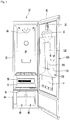
- FIG. 1 is a diagram showing the configuration of a clothes treatment apparatus according to an embodiment of the present invention
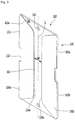
- FIG. 2 is a diagram showing a state in which a press door of a pants crease management apparatus according to an embodiment of the present invention is opened.
- the clothes treatment apparatus 10 includes a cabinet 20.
- the cabinet 20 includes a treatment chamber 25 in which clothes are received to remove wrinkles or odors of clothes through steam or air circulation and a machine room 40 disposed below the treatment chamber 25 and having a plurality of parts for clothes treatment.
- the cabinet 20 includes a partition plate 22 for partitioning the treatment chamber 25 and the machine room 40.
- the treatment chamber 25 may be formed above the partition plate 22 and the machine room 40 may be formed below the partition plate 22.
- the treatment chamber 25 may be defined by a space formed by the inner walls of the cabinet 20.
- the treatment chamber 25 may be defined by a space formed by the upper wall, the upper portions of the left and right walls and the upper portion of the rear wall of the cabinet 20.
- the machine room 40 may be defined by a space formed by the lower wall, the lower portions of the left and right walls and the lower portion of the rear wall of the cabinet 20.
- a clothes hanger 60 for hanging a hanger for hanging clothes is provided inside the cabinet 20.
- the clothes hanger 60 may be disposed on the upper portion of the treatment chamber 25.
- the clothes hanger 60 may be configured to be moved in a plurality of directions by a driving device such as a motor.
- the plurality of directions includes a front-and-back direction, an upper-and-lower direction and a left-and-right direction.
- the clothes treatment apparatus 10 further includes a discharging portion 50 for discharging steam or heated air (hot air) into the treatment chamber 25.
- the discharging portion 50 may be formed in a portion where the rear wall of the cabinet 20 and the rear portion of the partition wall 22 meet.
- the clothes treatment apparatus 10 further includes an inlet 55 for discharging, toward the machine room 40, air in the treatment chamber 25 and, more particularly, air including moisture, contaminant particles and odor particles after treating clothes in the treatment chamber 25.
- the inlet 55 may be formed in the front portion of the partition plate 22.
- the clothes treatment apparatus 10 may include a plurality of tanks 80 and 90 disposed on the front portion of the machine room 40.
- the plurality of tanks 80 and 90 may include a water supply tank 80 for supplying water to a steam generation apparatus (not shown). Water of the water supply tank 80 may be supplied to the steam generation apparatus through a water supply pump (not shown).
- the steam generation apparatus may be provided in the machine room 40.
- the plurality of tanks 80 and 90 may further include a drain tank 90 for collecting and storing condensate water generated in the treatment chamber 25 or condensate water generated in a heat pump device (not shown). Condensate water generated in the heat pump device may flow into the drain tank 90 through a drain pump (not shown).
- the heat pump device may be provided in the machine room 40.
- the water supply tank 80 and the drain tank 90 are exposed at the lower portion of the clothes treatment apparatus 10 when a door is opened and may be detached by a user.
- the user may detach the water supply tank 80 to supply water or detach the drain tank 90 to remove water stored in the drain tank 90.
- the clothes treatment apparatus 10 further includes a door 30 for opening or closing the treatment chamber 25.
- the door 30 may be disposed on the front side of the cabinet 20 and may be rotatably coupled to the cabinet 20.
- a pants crease management apparatus 100 for removing wrinkles of pants may be provided on a rear surface, that is, an inner surface, of the door 30.
- a pants hanger 32 for hanging a hanger 33 for hanging pants is provided above the pants crease management apparatus 100. The user may hang pants on the hanger and then hang the hanger on the pants hanger 32.
- the pants may be hanged on the pants crease management apparatus 100 to be flattened and fixed.
- steam or hot air may be supplied to the pants crease management apparatus 100 such that wrinkles of the pants are removed and a crease may be put in a desired direction.
- the pants crease management apparatus 100 includes a press plate 110 coupled to the rear surface of the door 30 and a press door 150 coupled to the front side of the press plate 110.
- the press plate 110 or the press door 150 may be made of a metal or plastic material.
- the pants P hanged on the pants hanger 32 are placed on the front side of the press plate 110 and the door 150 may be closed in front of the pants P.
- the pants P are pressed between the press plate 110 and the press door 150.
- a crease may be put in the pants P. That is, the pants P is placed in the pants crease management apparatus 100, thereby being ironed.
- the press door 150 includes a door body 151 having a through-hole 153 formed therein.
- the through-hole 153 is formed at a substantially central portion of the door body 151 and steam or hot air present in the treatment chamber 25 may be applied to the pants P hanged on the back side of the press door 150 through the through-hole 153.
- the press door 150 may be rotatably coupled to the door 30.
- the press door 150 includes a hinge 152 coupled to the door 30.
- the hinge 152 may be provided on one side, for example, the left side, of the door body 151.
- a plurality of hinges 152 may be provided.
- the plurality of hinges 152 may be arranged on the left side of the door body 151 to be spaced apart from each other in the upper-and-lower direction.
- the door body 151 includes latches 155 and 156 coupled to the door 30.
- the latches 155 and 156 include a first latch 155 provided on one side of the door body 151 and a second latch 156 provided on the other side of the door body 151.
- the first latch 155 may be provided on the left side of the door body 151 and the second latch 156 may be provided on the right side of the door body 151.
- the first latch 155 may be disposed between the plurality of hinges 152 in the upper-and-lower direction.
- the height of the first latch 155 may be equal to that of the second latch 156.
- the door 30 includes a first latch coupling portion 35 coupled to the first latch 155 and a second latch coupling portion 36 coupled to the second latch 156.
- the pants crease management apparatus 100 further includes a film 130 disposed between the press plate 110 and the press door 150 to press the pants P.
- the film 130 may be made of a flexible material.
- the film 130 may be configured to have a relatively small thickness and to have bending rigidity enough not to be easily bent by pressure, thereby providing pressing force to the pants P.
- the film 130 may be made of a plastic material.
- the film 130 may be made of polycarbonate, polypropylene, or plolyethylene terephthalate (PET).
- the thickness of the film 130 is 0.5 to 1.0 mm and the film may be relatively thin. By making the film 130 relatively thin, the user may easily manipulate the film 130. By pressing force applied from the press plate 110 and the press door 150, it is possible to prevent the film 130 from moving in a direction in which the pants P are wrinkled.
- the door 30 includes a clip 34 supporting the lower portion of the pants P.
- the clip 34 is configured to press the front side of the pants P in a state in which the pants are hanged, there preventing the pants P from fluctuating.
- the film 130 may be located between both portions, that is, the left and right portions, into which legs are inserted, of the pants P.
- the left portion of the pants may be placed on the front surface of the press plate 110 and the film 130 may be closely brought into contact with the front side of the left portion of the pants P.
- the right portion of the pants P is located on the front side of the film 130 and the clip 34 may be fitted into the front lower portion of the right portion of the pants P. That is, the right portion of the pants P may be moved to the back side of the clip 34 to be supported by the clip 34.
- the press door 150 may be located on the front side of the clip 34, thereby pressing the pants P.
- a crease may be put in the pants P and wrinkles may be removed by the pants crease management apparatus 100.
- FIG. 3 is a front perspective view showing the configuration of a press plate and a film according to an embodiment of the present invention
- FIG. 4 is a rear perspective view showing the configuration of the press plate and the film according to the embodiment of the present invention
- FIG. 5 is a perspective view showing a state in which the film according to the embodiment of the present invention moves forward
- FIG. 6 is a cross-sectional view taken along line VI-VI' of FIG. 1 .
- the press plate 110 includes a plate body 111 having a substantially polygonal panel shape.
- the plate body 111 may have a rectangular panel shape.
- the press plate 110 includes a door coupling portion 113 provided in the plate body 111 to be coupled to the door 30.
- a plurality of door coupling portions 113 may be provided on the upper and lower portions of the plate body 111.
- the door coupling portion 113 includes a hole, and a fastening member may penetrate through the hole to be coupled to the door 30.
- the film 130 may be movably provided on the front side of the press plate 110.
- the film 130 may be provided on both sides of the press plate 110.
- the film 130 includes a first film portion 130a coupled to the left portion of the press plate 110 and a second film portion 130b coupled to the right portion of the press plate 110.
- the first film portion 130a and the second film portion 130b may be disposed to be symmetrical with respect to the vertical center line f1 of the press plate 110.
- the vertical center line l1 may be understood as a line passing through the plurality of door coupling portions 113. Since the first and second film portions 130a and 130b have the same shape, the first film portion 130a will be focused upon and the description thereof is applicable to the second film portion 130b.
- the first film portion 130a includes a film body 131 composed of a thin plastic material.
- a film depression 132 in which the first latch coupling portion 35 is located is formed in the film body 131 in the upper-and-lower direction and is recessed rightward from the left end of the film body 131.
- the film depression 132 is formed in the second film portion 130b, and the second latch coupling portion 36 of the door 30 may be located in the film depression 132 of the second film portion 130b.
- the press plate 110 further includes a press depression 112 formed at a position corresponding to the film depression 132.
- the plate depression 112 may be configured to be recessed in both sides of the plate body 111, and the first and second latch coupling portions 35 and 36 may be located in both plate depression 112.
- the first film portion 130a includes film fixing portions 135a and 135b coupled to the press plate 110.
- the film fixing portions 135a and 135b may extend backward from the film body 131 to be coupled to the back surface of the press plate 110. That is, the film body 131 may be located on the front side of the press plate 110, and the film fixing portions 135a and 135b may be coupled to the back surface of the press plate 110. Since the film 130 is made of a plastic material, such a coupling structure is possible.
- Reinforcement ribs 117 for increasing the strength of the press plate 110 is provided on the back surface of the press plate 110.
- a plurality of reinforcement ribs 117 is provided and may extend to cross each other. By the plurality of reinforcement ribs 117, it is possible to prevent the press plate 110 from being bent.
- the film fixing portions 135a and 135b include a first fixing portion 135a provided on the upper portion of the film body 131 and a second fixing portion 135b provided on the lower portion of the film body 131.
- the film depression 132 may be formed between the first and second fixing portions 135a and 135b.
- the press plate 110 further includes a hook 115 coupled to the first and second fixing portions 135a and 135b.
- the hook 115 may be configured to protrude backward from the back surface of the press plate 110 and to be inserted or hooked into or to the first and second fixing portions 135a and 135b.
- the second film portion 130b includes the first and second fixing portions 135a and 135b and the first and second fixing portions 135a and 135b of the second film portion 130b may be coupled to the hook 115 provided on the press plate 110.
- the first and second film portions 130a and 130b may be configured to have a substantially trapezoidal shape. Specifically, the left and right ends of the first and second film portions 130a and 130b may form the lower and upper sides of the trapezoid parallel to each other, and the upper and lower ends of the first and second film portions 130a and 130b may form sides connecting the lower and upper sides of the trapezoid.
- the first and second film portions 130a and 130b may be located to be spaced apart from each other. That is, the first side end 133a forming the right end of the first film portion 130a and the second side end 133b forming the left end of the second film portion 130b may be spaced apart from each other by a first distance w1.
- the user may independently manipulate the first and second film portions 130a and 130b in a state in which the first and second film portions 130a and 130b do not interfere with each other.
- An inclined surface 131a inclined downward toward the first side end 133a is formed in the upper end of the first film portion 130a.
- the inclined surface 131a may extend to be inclined so as to form a set angle ⁇ 1 with respect to the upper end of the press plate 110.
- the set angle ⁇ 1 may be in a range of 30 to 60°.
- the inclined surface 131a may also be formed in the upper end of the second film portion 130b.
- the film body 131 of each of the first film portion 130a and the second film portion 130b may move in a direction forward away from the front surface of the press plate 110.
- the film body 131 provided in each of the first and second film portions 130a and 130b may move forward from the first and second fixing portions 135a and 135b. Accordingly, the user may hang the pants P and then move the film 130 forward such that the film is sandwiched between both portions of the pants P.
- the film 130 may be disposed between both portions, that is, the first side portion P1, into which the left leg is inserted, and the second side portion P2, into which the right leg is inserted, of the pants P. Substantially, it is not easy to accurately align the first side portion P1 and the second side portion P2 in a line in a state in which the first and second side portions are placed in the pants crease management apparatus 100. As shown in FIG. 6 , the first and second side portions are spaced apart from each other by a predetermined distance ⁇ S1 in the left-and-right direction.
- the first side portion P1 is pressed by force F1 applied between the press plate 110 and the film 130, and the second side portion P2 may be pressed by force F2 applied between the film 130 and the press door 150. That is, since pressing force F1+F2 is applied to the pants P, round wrinkles appearing when pressing force is small may be prevented and a crease Pw may be formed. In addition, wrinkles of the other portion of the pants P may be removed.
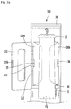
- FIGS. 7a and 7b are diagrams showing a state of operating the pants crease management apparatus according to the embodiment of the present invention. The order of operating the pants crease management apparatus 100 will be described.
- the pants P are hanged on the pants hanger 32 and the first side portion P1 of the pants P is located on the press plate 110.
- the film 130 is sandwiched between the first and second side portions P1 and P2 and the front surface of the first side portion P1 is pressed.
- first pressing force F1 may be applied from the film 130 to the first side portion P1 ( FIG. 7a ).
- the second side portion P2 of the pants P is located on the front side of the film 130 and the lower portion of the second side portion P2 may be fitted into the back side of the clip 34 ( FIG. 7b ).
- the press door 150 presses the second side portion P2 backward, and second pressing force may be applied from the film 130 to the second side portion P2 ( FIG. 7b ).
- the pants crease management apparatus 10 By operation of the pants crease management apparatus 10, it is possible to put a crease in the first and second side portions of the pants P and to remove wrinkles.
- both portions of pants are disposed with a film interposed therebetween and are pressed by the film, it is possible to reduce movement of the pants when a crease is put in the pants.
- the film is formed of plastic resin, for example, polycarbonate, polypropylene or plolyethylene terephthalate (PET), it is possible to press the pants while the film is not easily deformed by heat.
- plastic resin for example, polycarbonate, polypropylene or plolyethylene terephthalate (PET)
- both side ends of the film are spaced apart from each other such that the pants are exposed to the outside of the film, it is possible to easily apply the environment (high-temperature/high-humidity environment such as steam and hot air) of the treatment chamber of the clothes treatment apparatus to the pants.
- the film since the film is hooked to both sides of the press plate, the film may move in a state of being firmly supported by the pants crease management apparatus.
Description
- The present invention relates to a clothes treatment apparatus.
- A clothes treatment apparatus refers to an apparatus for managing clothes such as washing, drying or wrinkle reduction of clothes in the home or at a laundry. For example, the clothes treatment apparatus includes a washing machine for washing clothes, a dryer for drying clothes, a washing and drying machine for performing a washing function and a drying function, a refresher for refreshing clothes, and a steamer for reducing unnecessary wrinkles of clothes.
- A refresher is an apparatus for making the condition of clothes pleasant and fresh, and performs a function for drying clothes, supplying fragrance, preventing static electricity from occurring in clothes, or reducing wrinkles of clothes.
- The steamer is an apparatus for supplying steam to clothes to remove wrinkles of the clothes. The steamer removes wrinkles of clothes without directly applying heat to the clothes like a general iron.
- The clothes treatment apparatus including the functions of the refresher and the steamer may perform a function for removing wrinkles and odors of clothes received therein using steam and hot air.
- The clothes treatment apparatus may include a pants crease management apparatus for putting a crease in pants received therein. Due to the features of the pants, it is difficult to accurately align both portions (a portion into which a left leg is fitted and a portion into which a right leg is fitted) of the pants in the pants crease management apparatus.
- Accordingly, it is necessary to firmly fix the pants in the pants crease management apparatus in a state in which both portions, in which creases need to be put, of the pants are aligned.
- However, in a conventional pants crease management apparatus, both portions of the pants are not firmly fixed and thus are moved by steam or hot air. When a creasing process is performed in this state, creases may be put in a direction undesired by a user, thereby causing wrinkles.
- A clothes treatment apparatus with the features of the preamble of claim 1 is known from
EP 2826911 A1 . - Patent Document
- 1. Publication No. (Publication Date)
10-2017-0084454 (July 20, 2017 - 2. Title of the Invention: Clothes treatment apparatus
- An object of the present invention is to provide a clothes treatment apparatus including a pants crease management apparatus capable of firmly fixing both portions of pants.
- In particular, another object of the present invention is to provide a clothes treatment apparatus capable of easily fixing pants by providing a film for pressing both portions of the pants.
- In addition, another object of the present invention is to provide a clothes treatment apparatus capable of pressing pants while a film is not easily deformed by heat, by optimally setting a material or thickness of the film.
- In addition, another object of the present invention is to provide a clothes treatment apparatus capable of enabling a user to easily operate a film and pants while both portions of the pants are pressed by the film, by improving the structure of the film.
- In addition, another object of the present invention is to provide a clothes treatment apparatus including a film movably provided in a state of being firmly supported by a pants crease management apparatus.
- A clothes treatment apparatus according to an embodiment of the present invention includes a pants crease management apparatus provided on a rear surface of a door, thereby removing wrinkles of pants and putting a crease in the pants.
- The pants crease management apparatus includes a film disposed between a press plate and a press door and sandwiched between both portions of the pants P.
- The film is configured to press both portions of the pants P, thereby easily putting a crease in the pants.
- Since the film is formed of a flexible material and has a relatively small thickness, the film can be easily manipulated and apply excellent pressing force to the pants.
- The film includes a plurality of film portions fixed to both sides of the press plate, thereby easily inserting the plurality of film portions into the pants P.
- The film includes a first film portion fixed to one side of the press plate and a second film portion fixed to the other side of the press plate.
- The film is hooked to the press plate.
- The film includes a film body located on a front side of the press plate and a film fixing portion extending backward from the film body and coupled to a back surface of the press plate.
- The first film portion and the second film portion are disposed to be symmetrical with respect to a vertical center line ℓ1 of the press plate.
- A first side end forming a right end of the first film portion and a second side end forming a left end of the second film portion are spaced apart from each other.
- An inclined surface inclined downward toward the first side end is formed in an upper end of the first film portion, and the inclined surface is inclined from the upper end of the press plate by a set angle θ1.
- An inclined surface inclined downward toward the second side end is formed in an upper end of the second film portion, and the inclined surface is inclined from the upper end of the press plate by a set angle θ1.
- A latch provided on the press door and a latch coupling portion provided on the door and coupled to the latch may be further included.
- The film includes a film depression recessed from one surface of the film, and the film coupling portion is located in the film depression.
- A clothes treatment apparatus according to another embodiment of the present invention includes a press plate, a press door coupled to the press plate and a flexible film movably disposed between the press plate and the press door.
-
-
FIG. 1 is a diagram showing the configuration of a clothes treatment apparatus according to an embodiment of the present invention. -
FIG. 2 is a diagram showing a state in which a press door of a pants crease management apparatus according to an embodiment of the present invention is opened. -
FIG. 3 is a front perspective view showing the configuration of a press plate and a film according to an embodiment of the present invention. -
FIG. 4 is a rear perspective view showing the configuration of the press plate and the film according to the embodiment of the present invention. -
FIG. 5 is a perspective view showing a state in which the film according to the embodiment of the present invention moves forward. -
FIG. 6 is a cross-sectional view taken along line VI-VI' ofFIG. 1 . -
FIGS. 7a and7b are diagrams showing a state of operating the pants crease management apparatus according to the embodiment of the present invention. - Hereinafter, the embodiments of the present invention will be described with reference to the accompanying drawings. It is to be understood, however, that the scope is not limited to the disclosed embodiments, and those skilled in the art may easily suggest other embodiments within the same scope of the idea.
-
FIG. 1 is a diagram showing the configuration of a clothes treatment apparatus according to an embodiment of the present invention, andFIG. 2 is a diagram showing a state in which a press door of a pants crease management apparatus according to an embodiment of the present invention is opened. - Referring to
FIGS. 1 and2 , theclothes treatment apparatus 10 according to the embodiment of the present invention includes acabinet 20. - The
cabinet 20 includes atreatment chamber 25 in which clothes are received to remove wrinkles or odors of clothes through steam or air circulation and amachine room 40 disposed below thetreatment chamber 25 and having a plurality of parts for clothes treatment. - The
cabinet 20 includes apartition plate 22 for partitioning thetreatment chamber 25 and themachine room 40. Thetreatment chamber 25 may be formed above thepartition plate 22 and themachine room 40 may be formed below thepartition plate 22. - The
treatment chamber 25 may be defined by a space formed by the inner walls of thecabinet 20. For example, thetreatment chamber 25 may be defined by a space formed by the upper wall, the upper portions of the left and right walls and the upper portion of the rear wall of thecabinet 20. In addition, themachine room 40 may be defined by a space formed by the lower wall, the lower portions of the left and right walls and the lower portion of the rear wall of thecabinet 20. - A
clothes hanger 60 for hanging a hanger for hanging clothes is provided inside thecabinet 20. Theclothes hanger 60 may be disposed on the upper portion of thetreatment chamber 25. Theclothes hanger 60 may be configured to be moved in a plurality of directions by a driving device such as a motor. For example, the plurality of directions includes a front-and-back direction, an upper-and-lower direction and a left-and-right direction. - The
clothes treatment apparatus 10 further includes a dischargingportion 50 for discharging steam or heated air (hot air) into thetreatment chamber 25. For example, the dischargingportion 50 may be formed in a portion where the rear wall of thecabinet 20 and the rear portion of thepartition wall 22 meet. - The
clothes treatment apparatus 10 further includes an inlet 55 for discharging, toward themachine room 40, air in thetreatment chamber 25 and, more particularly, air including moisture, contaminant particles and odor particles after treating clothes in thetreatment chamber 25. The inlet 55 may be formed in the front portion of thepartition plate 22. - The
clothes treatment apparatus 10 may include a plurality oftanks machine room 40. The plurality oftanks water supply tank 80 for supplying water to a steam generation apparatus (not shown). Water of thewater supply tank 80 may be supplied to the steam generation apparatus through a water supply pump (not shown). The steam generation apparatus may be provided in themachine room 40. - The plurality of
tanks drain tank 90 for collecting and storing condensate water generated in thetreatment chamber 25 or condensate water generated in a heat pump device (not shown). Condensate water generated in the heat pump device may flow into thedrain tank 90 through a drain pump (not shown). The heat pump device may be provided in themachine room 40. - The
water supply tank 80 and thedrain tank 90 are exposed at the lower portion of theclothes treatment apparatus 10 when a door is opened and may be detached by a user. The user may detach thewater supply tank 80 to supply water or detach thedrain tank 90 to remove water stored in thedrain tank 90. - The
clothes treatment apparatus 10 further includes adoor 30 for opening or closing thetreatment chamber 25. For example, thedoor 30 may be disposed on the front side of thecabinet 20 and may be rotatably coupled to thecabinet 20. - A pants
crease management apparatus 100 for removing wrinkles of pants may be provided on a rear surface, that is, an inner surface, of thedoor 30. A pantshanger 32 for hanging ahanger 33 for hanging pants is provided above the pantscrease management apparatus 100. The user may hang pants on the hanger and then hang the hanger on thepants hanger 32. - The pants may be hanged on the pants
crease management apparatus 100 to be flattened and fixed. During operation of theclothes treatment apparatus 10, steam or hot air may be supplied to the pantscrease management apparatus 100 such that wrinkles of the pants are removed and a crease may be put in a desired direction. - The pants
crease management apparatus 100 includes apress plate 110 coupled to the rear surface of thedoor 30 and apress door 150 coupled to the front side of thepress plate 110. Thepress plate 110 or thepress door 150 may be made of a metal or plastic material. - In
FIG. 2 , the pants P hanged on thepants hanger 32 are placed on the front side of thepress plate 110 and thedoor 150 may be closed in front of the pants P. The pants P are pressed between thepress plate 110 and thepress door 150. In this process, a crease may be put in the pants P. That is, the pants P is placed in the pantscrease management apparatus 100, thereby being ironed. - The
press door 150 includes adoor body 151 having a through-hole 153 formed therein. The through-hole 153 is formed at a substantially central portion of thedoor body 151 and steam or hot air present in thetreatment chamber 25 may be applied to the pants P hanged on the back side of thepress door 150 through the through-hole 153. - The
press door 150 may be rotatably coupled to thedoor 30. Specifically, thepress door 150 includes ahinge 152 coupled to thedoor 30. Thehinge 152 may be provided on one side, for example, the left side, of thedoor body 151. A plurality ofhinges 152 may be provided. The plurality ofhinges 152 may be arranged on the left side of thedoor body 151 to be spaced apart from each other in the upper-and-lower direction. - The
door body 151 includeslatches door 30. Thelatches first latch 155 provided on one side of thedoor body 151 and asecond latch 156 provided on the other side of thedoor body 151. For example, thefirst latch 155 may be provided on the left side of thedoor body 151 and thesecond latch 156 may be provided on the right side of thedoor body 151. - The
first latch 155 may be disposed between the plurality ofhinges 152 in the upper-and-lower direction. The height of thefirst latch 155 may be equal to that of thesecond latch 156. - The
door 30 includes a firstlatch coupling portion 35 coupled to thefirst latch 155 and a secondlatch coupling portion 36 coupled to thesecond latch 156. By coupling thelatches latch coupling portions press door 150 may not move when theclothes treatment apparatus 10 operates. When thepress door 150 is closed, the pants P may be easily pressed. - The pants
crease management apparatus 100 further includes afilm 130 disposed between thepress plate 110 and thepress door 150 to press the pants P. Thefilm 130 may be made of a flexible material. - The
film 130 may be configured to have a relatively small thickness and to have bending rigidity enough not to be easily bent by pressure, thereby providing pressing force to the pants P. - Specifically, the
film 130 may be made of a plastic material. For example, thefilm 130 may be made of polycarbonate, polypropylene, or plolyethylene terephthalate (PET). - The thickness of the
film 130 is 0.5 to 1.0 mm and the film may be relatively thin. By making thefilm 130 relatively thin, the user may easily manipulate thefilm 130. By pressing force applied from thepress plate 110 and thepress door 150, it is possible to prevent thefilm 130 from moving in a direction in which the pants P are wrinkled. - The
door 30 includes aclip 34 supporting the lower portion of the pants P. Theclip 34 is configured to press the front side of the pants P in a state in which the pants are hanged, there preventing the pants P from fluctuating. - The
film 130 may be located between both portions, that is, the left and right portions, into which legs are inserted, of the pants P. For example, inFIG. 2 , the left portion of the pants may be placed on the front surface of thepress plate 110 and thefilm 130 may be closely brought into contact with the front side of the left portion of the pants P. - The right portion of the pants P is located on the front side of the
film 130 and theclip 34 may be fitted into the front lower portion of the right portion of the pants P. That is, the right portion of the pants P may be moved to the back side of theclip 34 to be supported by theclip 34. In addition, thepress door 150 may be located on the front side of theclip 34, thereby pressing the pants P. - By this arrangement, a crease may be put in the pants P and wrinkles may be removed by the pants
crease management apparatus 100. -
FIG. 3 is a front perspective view showing the configuration of a press plate and a film according to an embodiment of the present invention,FIG. 4 is a rear perspective view showing the configuration of the press plate and the film according to the embodiment of the present invention,FIG. 5 is a perspective view showing a state in which the film according to the embodiment of the present invention moves forward, andFIG. 6 is a cross-sectional view taken along line VI-VI' ofFIG. 1 . - Referring to
FIGS. 3 to 6 , thepress plate 110 according to the embodiment of the present invention includes aplate body 111 having a substantially polygonal panel shape. For example, theplate body 111 may have a rectangular panel shape. - The
press plate 110 includes adoor coupling portion 113 provided in theplate body 111 to be coupled to thedoor 30. A plurality ofdoor coupling portions 113 may be provided on the upper and lower portions of theplate body 111. Thedoor coupling portion 113 includes a hole, and a fastening member may penetrate through the hole to be coupled to thedoor 30. - The
film 130 may be movably provided on the front side of thepress plate 110. Thefilm 130 may be provided on both sides of thepress plate 110. Specifically, thefilm 130 includes afirst film portion 130a coupled to the left portion of thepress plate 110 and asecond film portion 130b coupled to the right portion of thepress plate 110. - The
first film portion 130a and thesecond film portion 130b may be disposed to be symmetrical with respect to the vertical center line f1 of thepress plate 110. For example, the vertical center line ℓ1 may be understood as a line passing through the plurality ofdoor coupling portions 113. Since the first andsecond film portions first film portion 130a will be focused upon and the description thereof is applicable to thesecond film portion 130b. - The
first film portion 130a includes afilm body 131 composed of a thin plastic material. In thefilm body 131, afilm depression 132 in which the firstlatch coupling portion 35 is located is formed. Thefilm depression 132 is formed in the left center of thefilm body 131 in the upper-and-lower direction and is recessed rightward from the left end of thefilm body 131. By this configuration, when thefirst film portion 130a rotates forward about the left end thereof, thefilm body 131 may be prevented from interfering with the firstlatch coupling portion 35. - The
film depression 132 is formed in thesecond film portion 130b, and the secondlatch coupling portion 36 of thedoor 30 may be located in thefilm depression 132 of thesecond film portion 130b. - The
press plate 110 further includes apress depression 112 formed at a position corresponding to thefilm depression 132. Theplate depression 112 may be configured to be recessed in both sides of theplate body 111, and the first and secondlatch coupling portions plate depression 112. - The
first film portion 130a includesfilm fixing portions press plate 110. Thefilm fixing portions film body 131 to be coupled to the back surface of thepress plate 110. That is, thefilm body 131 may be located on the front side of thepress plate 110, and thefilm fixing portions press plate 110. Since thefilm 130 is made of a plastic material, such a coupling structure is possible. -
Reinforcement ribs 117 for increasing the strength of thepress plate 110 is provided on the back surface of thepress plate 110. A plurality ofreinforcement ribs 117 is provided and may extend to cross each other. By the plurality ofreinforcement ribs 117, it is possible to prevent thepress plate 110 from being bent. - The
film fixing portions first fixing portion 135a provided on the upper portion of thefilm body 131 and asecond fixing portion 135b provided on the lower portion of thefilm body 131. Thefilm depression 132 may be formed between the first andsecond fixing portions - The
press plate 110 further includes ahook 115 coupled to the first andsecond fixing portions hook 115 may be configured to protrude backward from the back surface of thepress plate 110 and to be inserted or hooked into or to the first andsecond fixing portions - Similarly, the
second film portion 130b includes the first andsecond fixing portions second fixing portions second film portion 130b may be coupled to thehook 115 provided on thepress plate 110. - The first and
second film portions second film portions second film portions - The first and
second film portions first side end 133a forming the right end of thefirst film portion 130a and thesecond side end 133b forming the left end of thesecond film portion 130b may be spaced apart from each other by a first distance w1. By this configuration, the user may independently manipulate the first andsecond film portions second film portions - An
inclined surface 131a inclined downward toward thefirst side end 133a is formed in the upper end of thefirst film portion 130a. Theinclined surface 131a may extend to be inclined so as to form a set angle θ1 with respect to the upper end of thepress plate 110. For example, the set angle θ1 may be in a range of 30 to 60°. By this configuration, the user may easily grip and manipulate theinclined surface 131a of thefirst film portion 130a. - The
inclined surface 131a may also be formed in the upper end of thesecond film portion 130b. - Referring to
FIG. 5 , thefilm body 131 of each of thefirst film portion 130a and thesecond film portion 130b may move in a direction forward away from the front surface of thepress plate 110. - That is, by the material characteristics of the
film 130, thefilm body 131 provided in each of the first andsecond film portions second fixing portions film 130 forward such that the film is sandwiched between both portions of the pants P. - Referring to
FIG. 6 , thefilm 130 may be disposed between both portions, that is, the first side portion P1, into which the left leg is inserted, and the second side portion P2, into which the right leg is inserted, of the pants P. Substantially, it is not easy to accurately align the first side portion P1 and the second side portion P2 in a line in a state in which the first and second side portions are placed in the pantscrease management apparatus 100. As shown inFIG. 6 , the first and second side portions are spaced apart from each other by a predetermined distance ΔS1 in the left-and-right direction. - In a state in which the
press door 150 is closed, the first side portion P1 is pressed by force F1 applied between thepress plate 110 and thefilm 130, and the second side portion P2 may be pressed by force F2 applied between thefilm 130 and thepress door 150. That is, since pressing force F1+F2 is applied to the pants P, round wrinkles appearing when pressing force is small may be prevented and a crease Pw may be formed. In addition, wrinkles of the other portion of the pants P may be removed. -
FIGS. 7a and7b are diagrams showing a state of operating the pants crease management apparatus according to the embodiment of the present invention. The order of operating the pantscrease management apparatus 100 will be described. - The pants P are hanged on the
pants hanger 32 and the first side portion P1 of the pants P is located on thepress plate 110. In addition, thefilm 130 is sandwiched between the first and second side portions P1 and P2 and the front surface of the first side portion P1 is pressed. By this operation, first pressing force F1 may be applied from thefilm 130 to the first side portion P1 (FIG. 7a ). - The second side portion P2 of the pants P is located on the front side of the
film 130 and the lower portion of the second side portion P2 may be fitted into the back side of the clip 34 (FIG. 7b ). When thepress door 150 is closed, thepress door 150 presses the second side portion P2 backward, and second pressing force may be applied from thefilm 130 to the second side portion P2 (FIG. 7b ). - By operation of the pants
crease management apparatus 10, it is possible to put a crease in the first and second side portions of the pants P and to remove wrinkles. - According to the present invention, since both portions of pants are disposed with a film interposed therebetween and are pressed by the film, it is possible to reduce movement of the pants when a crease is put in the pants.
- In addition, since the film is formed of plastic resin, for example, polycarbonate, polypropylene or plolyethylene terephthalate (PET), it is possible to press the pants while the film is not easily deformed by heat.
- In addition, since a plurality of films is movably provided on both sides of the press plate, it is possible to easily press both portions of the pants, in which a crease is put.
- In addition, since both side ends of the film are spaced apart from each other such that the pants are exposed to the outside of the film, it is possible to easily apply the environment (high-temperature/high-humidity environment such as steam and hot air) of the treatment chamber of the clothes treatment apparatus to the pants.
- In addition, since the upper end of the film is inclined downward, it is possible to easily dispose the pants on both sides of the film.
- In addition, since the film is hooked to both sides of the press plate, the film may move in a state of being firmly supported by the pants crease management apparatus.
Claims (15)
- A clothes treatment apparatus (10) comprising:a case (20) having formed therein a treatment chamber (25), into which clothes are put;a door (30) coupled to the case to open or close the treatment chamber (25); anda pants crease management apparatus (100) provided on a rear surface of the door (30),wherein the pants crease management apparatus (100) includes:a press plate (110) coupled to the rear surface of the door (30) such that pants (P) are placed thereon; characterised in that the clothes treatment apparatus further comprisesa press door (150) openably provided on the press plate(110); anda film (130) disposed between the press plate (110) and the press door (150), the film (130) being sandwiched between both side portions of the pants (P).
- The clothes treatment apparatus (10) of claim 1, wherein the film (130) is formed of a flexible material.
- The clothes treatment apparatus (10) of claim 1 or 2,
wherein the film (130) is formed of a plastic material, and
wherein the plastic material includes polycarbonate, polypropylene or polyethylene terephthalate PET. - The clothes treatment apparatus (10) of any one of claims 1 to 3, wherein a thickness of the film (130) is in a range of 0.5 to 1.0 mm.
- The clothes treatment apparatus (10) of any one of claims 1 to 4, wherein the film includes:a first film portion (130a) fixed to a first side of the press plate (110); anda second film portion (130b) fixed to a second side of the press plate (110).
- The clothes treatment apparatus (10) of claim 5, wherein the first film portion (130a) or the second film portion (130b) is hooked to the press plate (110).
- The clothes treatment apparatus (10) of claim 5 or 6, wherein the first film portion (130a) and the second film portion (130b) are disposed to be symmetrical with respect to a vertical center line (ℓ1) of the press plate (110).
- The clothes treatment apparatus (10) of any one of claims 5 to 7,
wherein the first film portion (130a) is fixed to a left portion of the press plate (110) and the second film portion (130b) is fixed to a right portion of the press plate (110), and
wherein a first side end (133a) forming a right end of the first film portion (130a) and a second side end (133b) forming a left end of the second film portion (130b) are spaced apart from each other. - The clothes treatment apparatus (10) of any one of claims 5 to 8,
wherein an upper end of the first film portion (130a) is provided with an inclined surface (131a) inclined downward toward the first side end (133a), and
wherein the inclined surface (131a) is inclined from the upper end of the press plate (110) by a predetermined angle (θ1). - The clothes treatment apparatus (10) of claim 9,
wherein an upper end of the second film portion (130b) is provided with an inclined surface (131b) inclined downward toward the second side end (133b), and
wherein the inclined surface (131b) is inclined from the upper end of the press plate (110) by the predetermined angle (θ1). - The clothes treatment apparatus (10) of claim 9 or 10, wherein the predetermined angle (θ1) is in a range of 30 to 60°.
- The clothes treatment apparatus (10) of any one of claims 1 to 11, further comprising a hinge (152) configured to provide a rotation center of the press door (150),
wherein the press door (150) is coupled to the door (30) to rotate with respect to the hinge (152). - The clothes treatment apparatus (10) of claim 12, further comprising:a latch (155, 156) provided on the press door (150); anda latch coupling portion (35, 36) provided on the door (30), the latch coupling portion (35, 36) being coupled to the latch (155,156).
- The clothes treatment apparatus (10) of claim 12 or 13,
wherein the film (130) includes a film depression (132) recessed from one surface of the film (130), and
wherein the film coupling portion (35) is located in the film depression (132). - The clothes treatment apparatus (10) of any one of claims 1 to 14, wherein the film (130) includes:a film body (131) located on a front side of the press plate (110); anda film fixing portion (135a, 135b) extending backward from the film body (131) and coupled to a back surface of the press plate (110).
Priority Applications (2)
| Application Number | Priority Date | Filing Date | Title |
|---|---|---|---|
| EP20184937.9A EP3754094B1 (en) | 2018-02-22 | 2019-02-13 | Clothes treatment apparatus |
| EP23179448.8A EP4234801A3 (en) | 2018-02-22 | 2019-02-13 | Clothes treatment apparatus |
Applications Claiming Priority (1)
| Application Number | Priority Date | Filing Date | Title |
|---|---|---|---|
| KR1020180021194A KR102620273B1 (en) | 2018-02-22 | 2018-02-22 | Fabric managing apparatus |
Related Child Applications (3)
| Application Number | Title | Priority Date | Filing Date |
|---|---|---|---|
| EP23179448.8A Division EP4234801A3 (en) | 2018-02-22 | 2019-02-13 | Clothes treatment apparatus |
| EP20184937.9A Division EP3754094B1 (en) | 2018-02-22 | 2019-02-13 | Clothes treatment apparatus |
| EP20184937.9A Division-Into EP3754094B1 (en) | 2018-02-22 | 2019-02-13 | Clothes treatment apparatus |
Publications (2)
| Publication Number | Publication Date |
|---|---|
| EP3530801A1 EP3530801A1 (en) | 2019-08-28 |
| EP3530801B1 true EP3530801B1 (en) | 2020-08-26 |
Family
ID=65433555
Family Applications (3)
| Application Number | Title | Priority Date | Filing Date |
|---|---|---|---|
| EP23179448.8A Pending EP4234801A3 (en) | 2018-02-22 | 2019-02-13 | Clothes treatment apparatus |
| EP20184937.9A Active EP3754094B1 (en) | 2018-02-22 | 2019-02-13 | Clothes treatment apparatus |
| EP19156873.2A Active EP3530801B1 (en) | 2018-02-22 | 2019-02-13 | Clothes treatment apparatus |
Family Applications Before (2)
| Application Number | Title | Priority Date | Filing Date |
|---|---|---|---|
| EP23179448.8A Pending EP4234801A3 (en) | 2018-02-22 | 2019-02-13 | Clothes treatment apparatus |
| EP20184937.9A Active EP3754094B1 (en) | 2018-02-22 | 2019-02-13 | Clothes treatment apparatus |
Country Status (3)
| Country | Link |
|---|---|
| US (3) | US11060237B2 (en) |
| EP (3) | EP4234801A3 (en) |
| KR (2) | KR102620273B1 (en) |
Families Citing this family (10)
| Publication number | Priority date | Publication date | Assignee | Title |
|---|---|---|---|---|
| KR102620273B1 (en) * | 2018-02-22 | 2023-12-29 | 엘지전자 주식회사 | Fabric managing apparatus |
| RU2021129331A (en) * | 2018-04-03 | 2021-11-12 | ЭлДжи ЭЛЕКТРОНИКС ИНК. | CLOTHING DEVICE |
| KR102627707B1 (en) * | 2018-11-30 | 2024-01-23 | 삼성전자주식회사 | Clothes care apparatus and control method thereof |
| KR20210062398A (en) | 2019-11-21 | 2021-05-31 | 삼성전자주식회사 | Clothes treatment apparatus and cotrol method thereof |
| GB202003558D0 (en) * | 2020-03-11 | 2020-04-29 | Quadron Tech Ltd | Automatic ironing apparatus |
| KR20210136296A (en) * | 2020-05-07 | 2021-11-17 | 엘지전자 주식회사 | Laundry Treatment Apparatus |
| JP1720853S (en) * | 2020-11-12 | 2022-07-28 | Footwear washing and care cabinet | |
| USD1018795S1 (en) * | 2020-11-13 | 2024-03-19 | Lg Electronics Inc. | Footwear care machine |
| USD1011660S1 (en) * | 2021-08-04 | 2024-01-16 | Samsung Electronics Co., Ltd. | Clothing care machine |
| USD1011659S1 (en) * | 2021-08-04 | 2024-01-16 | Samsung Electronics Co., Ltd. | Clothing care machine |
Family Cites Families (24)
| Publication number | Priority date | Publication date | Assignee | Title |
|---|---|---|---|---|
| US1763816A (en) * | 1927-06-16 | 1930-06-17 | American Laundry Mach Co | Clamping mechanism for pressing machines |
| US3117704A (en) * | 1961-03-21 | 1964-01-14 | Jerry N Mcmillan | Apparatus for finishing trousers |
| DE1164970B (en) * | 1961-08-26 | 1964-03-12 | Johann Heinrich Oelkers | Ironing press for pants |
| FR1480150A (en) * | 1965-01-21 | 1967-05-12 | Bowe Bohler & Weber K G Maschi | Device for ironing pants |
| EP0156743A1 (en) * | 1984-03-06 | 1985-10-02 | Patrice Duplessy | Portable and folding trousers press |
| US4694146A (en) * | 1985-10-28 | 1987-09-15 | Demars Robert A | Bracket mounted towel drying cabinet |
| US5305484A (en) * | 1988-01-13 | 1994-04-26 | J.S.F. Holdings (Cork) Limited | Clothes steaming and drying cabinet |
| US5359792A (en) * | 1991-09-10 | 1994-11-01 | Matsushita Electric Industrial Co., Ltd. | Free standing, upright clothes press |
| IT1294958B1 (en) * | 1995-08-01 | 1999-04-23 | Mino Antonio | TROUSERS MACHINE |
| JPH10192599A (en) * | 1997-01-10 | 1998-07-28 | Toshiba Corp | Press for clothes |
| US5970637A (en) * | 1998-05-29 | 1999-10-26 | American Laundry Machinery, Inc. | Automatic shirt pressing apparatus including a vacuum system and associated method |
| JP2001058100A (en) * | 1999-08-20 | 2001-03-06 | Sankosha:Kk | Trouser press finishing device |
| EP1420672B1 (en) * | 2001-08-29 | 2005-12-07 | Exeq S.A. | Compact automatic ironing press for trousers |
| ITMO20060224A1 (en) * | 2006-07-11 | 2008-01-12 | Barbanti Carlo Snc | PERFECT STRAIGHTENING MACHINE, PARTICULARLY FOR IRONING PANTS |
| KR20120091799A (en) * | 2011-02-10 | 2012-08-20 | 엘지전자 주식회사 | Laundry fixing apparatus and laundry treating machine having the same |
| KR101821203B1 (en) * | 2011-10-20 | 2018-01-23 | 엘지전자 주식회사 | Accessary for a clothes dryer |
| KR102099175B1 (en) * | 2013-07-17 | 2020-05-22 | 엘지전자 주식회사 | Laundry Treating Apparatus |
| USD732774S1 (en) * | 2013-09-11 | 2015-06-23 | Lg Electronics Inc. | Door for clothes management apparatus |
| KR102099179B1 (en) * | 2013-12-05 | 2020-04-09 | 엘지전자 주식회사 | Laundry Treating Apparatus |
| KR102154529B1 (en) * | 2014-12-19 | 2020-09-10 | 엘지전자 주식회사 | Apparatus for treating clothes |
| EP3034684B1 (en) * | 2014-12-19 | 2017-10-04 | LG Electronics Inc. | Clothes treatment apparatus |
| KR102506531B1 (en) | 2016-01-12 | 2023-03-06 | 엘지전자 주식회사 | Fabric treating apparatus |
| KR102599103B1 (en) * | 2016-11-11 | 2023-11-06 | 엘지전자 주식회사 | Laundry Treating Apparatus |
| KR102620273B1 (en) * | 2018-02-22 | 2023-12-29 | 엘지전자 주식회사 | Fabric managing apparatus |
-
2018
- 2018-02-22 KR KR1020180021194A patent/KR102620273B1/en active IP Right Grant
-
2019
- 2019-02-13 EP EP23179448.8A patent/EP4234801A3/en active Pending
- 2019-02-13 EP EP20184937.9A patent/EP3754094B1/en active Active
- 2019-02-13 US US16/274,367 patent/US11060237B2/en active Active
- 2019-02-13 EP EP19156873.2A patent/EP3530801B1/en active Active
-
2021
- 2021-06-21 US US17/353,146 patent/US11713537B2/en active Active
-
2023
- 2023-07-24 US US18/225,451 patent/US20230366140A1/en active Pending
- 2023-12-26 KR KR1020230191407A patent/KR20240004181A/en active Search and Examination
Non-Patent Citations (1)
| Title |
|---|
| None * |
Also Published As
| Publication number | Publication date |
|---|---|
| EP4234801A2 (en) | 2023-08-30 |
| KR102620273B1 (en) | 2023-12-29 |
| EP4234801A3 (en) | 2023-10-18 |
| EP3530801A1 (en) | 2019-08-28 |
| US20210310181A1 (en) | 2021-10-07 |
| US11713537B2 (en) | 2023-08-01 |
| US20230366140A1 (en) | 2023-11-16 |
| EP3754094A1 (en) | 2020-12-23 |
| US11060237B2 (en) | 2021-07-13 |
| KR20240004181A (en) | 2024-01-11 |
| KR20190101172A (en) | 2019-08-30 |
| US20190257025A1 (en) | 2019-08-22 |
| EP3754094B1 (en) | 2023-07-19 |
Similar Documents
| Publication | Publication Date | Title |
|---|---|---|
| EP3530801B1 (en) | Clothes treatment apparatus | |
| EP2826911B1 (en) | Laundry treating apparatus | |
| AU2021201099B2 (en) | Laundry treating apparatus | |
| JP2023075295A (en) | Clothing treatment device | |
| EP1146162A2 (en) | Clothes drying and dewrinkling cabinet | |
| US11535976B2 (en) | Laundry treating apparatus | |
| KR20160075032A (en) | Apparatus for treating clothes | |
| KR101988323B1 (en) | Laundry Treating Apparatus | |
| KR20240027649A (en) | A clothes treating apparatus | |
| US20160215440A1 (en) | Clothes refreshing appliance | |
| AU2023208106A1 (en) | Laundry treating apparatus | |
| CN113308867B (en) | Clothes treating apparatus | |
| KR102378141B1 (en) | Laundry Treating Apparatus | |
| KR101405958B1 (en) | Laundry treating apparatus | |
| KR102158701B1 (en) | Laundry Treating Apparatus | |
| KR20200110284A (en) | Laundry Treating Apparatus | |
| KR20200110282A (en) | Laundry Treating Apparatus |
Legal Events
| Date | Code | Title | Description |
|---|---|---|---|
| PUAI | Public reference made under article 153(3) epc to a published international application that has entered the european phase |
Free format text: ORIGINAL CODE: 0009012 |
|
| STAA | Information on the status of an ep patent application or granted ep patent |
Free format text: STATUS: REQUEST FOR EXAMINATION WAS MADE |
|
| 17P | Request for examination filed |
Effective date: 20190313 |
|
| AK | Designated contracting states |
Kind code of ref document: A1 Designated state(s): AL AT BE BG CH CY CZ DE DK EE ES FI FR GB GR HR HU IE IS IT LI LT LU LV MC MK MT NL NO PL PT RO RS SE SI SK SM TR |
|
| AX | Request for extension of the european patent |
Extension state: BA ME |
|
| RBV | Designated contracting states (corrected) |
Designated state(s): AL AT BE BG CH CY CZ DE DK EE ES FI FR GB GR HR HU IE IS IT LI LT LU LV MC MK MT NL NO PL PT RO RS SE SI SK SM TR |
|
| GRAP | Despatch of communication of intention to grant a patent |
Free format text: ORIGINAL CODE: EPIDOSNIGR1 |
|
| STAA | Information on the status of an ep patent application or granted ep patent |
Free format text: STATUS: GRANT OF PATENT IS INTENDED |
|
| RIC1 | Information provided on ipc code assigned before grant |
Ipc: D06F 73/02 20060101ALI20200203BHEP Ipc: D06F 58/10 20060101AFI20200203BHEP |
|
| INTG | Intention to grant announced |
Effective date: 20200310 |
|
| GRAS | Grant fee paid |
Free format text: ORIGINAL CODE: EPIDOSNIGR3 |
|
| GRAA | (expected) grant |
Free format text: ORIGINAL CODE: 0009210 |
|
| STAA | Information on the status of an ep patent application or granted ep patent |
Free format text: STATUS: THE PATENT HAS BEEN GRANTED |
|
| AK | Designated contracting states |
Kind code of ref document: B1 Designated state(s): AL AT BE BG CH CY CZ DE DK EE ES FI FR GB GR HR HU IE IS IT LI LT LU LV MC MK MT NL NO PL PT RO RS SE SI SK SM TR |
|
| REG | Reference to a national code |
Ref country code: GB Ref legal event code: FG4D |
|
| REG | Reference to a national code |
Ref country code: CH Ref legal event code: EP |
|
| REG | Reference to a national code |
Ref country code: AT Ref legal event code: REF Ref document number: 1306467 Country of ref document: AT Kind code of ref document: T Effective date: 20200915 |
|
| REG | Reference to a national code |
Ref country code: IE Ref legal event code: FG4D |
|
| REG | Reference to a national code |
Ref country code: DE Ref legal event code: R096 Ref document number: 602019000523 Country of ref document: DE |
|
| REG | Reference to a national code |
Ref country code: LT Ref legal event code: MG4D |
|
| PG25 | Lapsed in a contracting state [announced via postgrant information from national office to epo] |
Ref country code: FI Free format text: LAPSE BECAUSE OF FAILURE TO SUBMIT A TRANSLATION OF THE DESCRIPTION OR TO PAY THE FEE WITHIN THE PRESCRIBED TIME-LIMIT Effective date: 20200826 Ref country code: GR Free format text: LAPSE BECAUSE OF FAILURE TO SUBMIT A TRANSLATION OF THE DESCRIPTION OR TO PAY THE FEE WITHIN THE PRESCRIBED TIME-LIMIT Effective date: 20201127 Ref country code: PT Free format text: LAPSE BECAUSE OF FAILURE TO SUBMIT A TRANSLATION OF THE DESCRIPTION OR TO PAY THE FEE WITHIN THE PRESCRIBED TIME-LIMIT Effective date: 20201228 Ref country code: NO Free format text: LAPSE BECAUSE OF FAILURE TO SUBMIT A TRANSLATION OF THE DESCRIPTION OR TO PAY THE FEE WITHIN THE PRESCRIBED TIME-LIMIT Effective date: 20201126 Ref country code: BG Free format text: LAPSE BECAUSE OF FAILURE TO SUBMIT A TRANSLATION OF THE DESCRIPTION OR TO PAY THE FEE WITHIN THE PRESCRIBED TIME-LIMIT Effective date: 20201126 Ref country code: SE Free format text: LAPSE BECAUSE OF FAILURE TO SUBMIT A TRANSLATION OF THE DESCRIPTION OR TO PAY THE FEE WITHIN THE PRESCRIBED TIME-LIMIT Effective date: 20200826 Ref country code: HR Free format text: LAPSE BECAUSE OF FAILURE TO SUBMIT A TRANSLATION OF THE DESCRIPTION OR TO PAY THE FEE WITHIN THE PRESCRIBED TIME-LIMIT Effective date: 20200826 Ref country code: LT Free format text: LAPSE BECAUSE OF FAILURE TO SUBMIT A TRANSLATION OF THE DESCRIPTION OR TO PAY THE FEE WITHIN THE PRESCRIBED TIME-LIMIT Effective date: 20200826 |
|
| REG | Reference to a national code |
Ref country code: NL Ref legal event code: MP Effective date: 20200826 |
|
| REG | Reference to a national code |
Ref country code: AT Ref legal event code: MK05 Ref document number: 1306467 Country of ref document: AT Kind code of ref document: T Effective date: 20200826 |
|
| PG25 | Lapsed in a contracting state [announced via postgrant information from national office to epo] |
Ref country code: NL Free format text: LAPSE BECAUSE OF FAILURE TO SUBMIT A TRANSLATION OF THE DESCRIPTION OR TO PAY THE FEE WITHIN THE PRESCRIBED TIME-LIMIT Effective date: 20200826 Ref country code: LV Free format text: LAPSE BECAUSE OF FAILURE TO SUBMIT A TRANSLATION OF THE DESCRIPTION OR TO PAY THE FEE WITHIN THE PRESCRIBED TIME-LIMIT Effective date: 20200826 Ref country code: PL Free format text: LAPSE BECAUSE OF FAILURE TO SUBMIT A TRANSLATION OF THE DESCRIPTION OR TO PAY THE FEE WITHIN THE PRESCRIBED TIME-LIMIT Effective date: 20200826 Ref country code: RS Free format text: LAPSE BECAUSE OF FAILURE TO SUBMIT A TRANSLATION OF THE DESCRIPTION OR TO PAY THE FEE WITHIN THE PRESCRIBED TIME-LIMIT Effective date: 20200826 Ref country code: IS Free format text: LAPSE BECAUSE OF FAILURE TO SUBMIT A TRANSLATION OF THE DESCRIPTION OR TO PAY THE FEE WITHIN THE PRESCRIBED TIME-LIMIT Effective date: 20201226 |
|
| PG25 | Lapsed in a contracting state [announced via postgrant information from national office to epo] |
Ref country code: SM Free format text: LAPSE BECAUSE OF FAILURE TO SUBMIT A TRANSLATION OF THE DESCRIPTION OR TO PAY THE FEE WITHIN THE PRESCRIBED TIME-LIMIT Effective date: 20200826 Ref country code: EE Free format text: LAPSE BECAUSE OF FAILURE TO SUBMIT A TRANSLATION OF THE DESCRIPTION OR TO PAY THE FEE WITHIN THE PRESCRIBED TIME-LIMIT Effective date: 20200826 Ref country code: CZ Free format text: LAPSE BECAUSE OF FAILURE TO SUBMIT A TRANSLATION OF THE DESCRIPTION OR TO PAY THE FEE WITHIN THE PRESCRIBED TIME-LIMIT Effective date: 20200826 Ref country code: DK Free format text: LAPSE BECAUSE OF FAILURE TO SUBMIT A TRANSLATION OF THE DESCRIPTION OR TO PAY THE FEE WITHIN THE PRESCRIBED TIME-LIMIT Effective date: 20200826 Ref country code: RO Free format text: LAPSE BECAUSE OF FAILURE TO SUBMIT A TRANSLATION OF THE DESCRIPTION OR TO PAY THE FEE WITHIN THE PRESCRIBED TIME-LIMIT Effective date: 20200826 |
|
| REG | Reference to a national code |
Ref country code: DE Ref legal event code: R097 Ref document number: 602019000523 Country of ref document: DE |
|
| PG25 | Lapsed in a contracting state [announced via postgrant information from national office to epo] |
Ref country code: AL Free format text: LAPSE BECAUSE OF FAILURE TO SUBMIT A TRANSLATION OF THE DESCRIPTION OR TO PAY THE FEE WITHIN THE PRESCRIBED TIME-LIMIT Effective date: 20200826 Ref country code: AT Free format text: LAPSE BECAUSE OF FAILURE TO SUBMIT A TRANSLATION OF THE DESCRIPTION OR TO PAY THE FEE WITHIN THE PRESCRIBED TIME-LIMIT Effective date: 20200826 Ref country code: ES Free format text: LAPSE BECAUSE OF FAILURE TO SUBMIT A TRANSLATION OF THE DESCRIPTION OR TO PAY THE FEE WITHIN THE PRESCRIBED TIME-LIMIT Effective date: 20200826 |
|
| PG25 | Lapsed in a contracting state [announced via postgrant information from national office to epo] |
Ref country code: SK Free format text: LAPSE BECAUSE OF FAILURE TO SUBMIT A TRANSLATION OF THE DESCRIPTION OR TO PAY THE FEE WITHIN THE PRESCRIBED TIME-LIMIT Effective date: 20200826 |
|
| PLBE | No opposition filed within time limit |
Free format text: ORIGINAL CODE: 0009261 |
|
| STAA | Information on the status of an ep patent application or granted ep patent |
Free format text: STATUS: NO OPPOSITION FILED WITHIN TIME LIMIT |
|
| PG25 | Lapsed in a contracting state [announced via postgrant information from national office to epo] |
Ref country code: IT Free format text: LAPSE BECAUSE OF FAILURE TO SUBMIT A TRANSLATION OF THE DESCRIPTION OR TO PAY THE FEE WITHIN THE PRESCRIBED TIME-LIMIT Effective date: 20200826 |
|
| 26N | No opposition filed |
Effective date: 20210527 |
|
| PG25 | Lapsed in a contracting state [announced via postgrant information from national office to epo] |
Ref country code: SI Free format text: LAPSE BECAUSE OF FAILURE TO SUBMIT A TRANSLATION OF THE DESCRIPTION OR TO PAY THE FEE WITHIN THE PRESCRIBED TIME-LIMIT Effective date: 20200826 |
|
| PG25 | Lapsed in a contracting state [announced via postgrant information from national office to epo] |
Ref country code: MC Free format text: LAPSE BECAUSE OF FAILURE TO SUBMIT A TRANSLATION OF THE DESCRIPTION OR TO PAY THE FEE WITHIN THE PRESCRIBED TIME-LIMIT Effective date: 20200826 |
|
| REG | Reference to a national code |
Ref country code: BE Ref legal event code: MM Effective date: 20210228 |
|
| PG25 | Lapsed in a contracting state [announced via postgrant information from national office to epo] |
Ref country code: LU Free format text: LAPSE BECAUSE OF NON-PAYMENT OF DUE FEES Effective date: 20210213 |
|
| PG25 | Lapsed in a contracting state [announced via postgrant information from national office to epo] |
Ref country code: FR Free format text: LAPSE BECAUSE OF NON-PAYMENT OF DUE FEES Effective date: 20210228 Ref country code: IE Free format text: LAPSE BECAUSE OF NON-PAYMENT OF DUE FEES Effective date: 20210213 |
|
| PG25 | Lapsed in a contracting state [announced via postgrant information from national office to epo] |
Ref country code: BE Free format text: LAPSE BECAUSE OF NON-PAYMENT OF DUE FEES Effective date: 20210228 |
|
| REG | Reference to a national code |
Ref country code: CH Ref legal event code: PL |
|
| PG25 | Lapsed in a contracting state [announced via postgrant information from national office to epo] |
Ref country code: LI Free format text: LAPSE BECAUSE OF NON-PAYMENT OF DUE FEES Effective date: 20220228 Ref country code: CH Free format text: LAPSE BECAUSE OF NON-PAYMENT OF DUE FEES Effective date: 20220228 |
|
| PGFP | Annual fee paid to national office [announced via postgrant information from national office to epo] |
Ref country code: GB Payment date: 20230105 Year of fee payment: 5 Ref country code: DE Payment date: 20230105 Year of fee payment: 5 |
|
| PG25 | Lapsed in a contracting state [announced via postgrant information from national office to epo] |
Ref country code: CY Free format text: LAPSE BECAUSE OF FAILURE TO SUBMIT A TRANSLATION OF THE DESCRIPTION OR TO PAY THE FEE WITHIN THE PRESCRIBED TIME-LIMIT Effective date: 20200826 |
|
| PG25 | Lapsed in a contracting state [announced via postgrant information from national office to epo] |
Ref country code: HU Free format text: LAPSE BECAUSE OF FAILURE TO SUBMIT A TRANSLATION OF THE DESCRIPTION OR TO PAY THE FEE WITHIN THE PRESCRIBED TIME-LIMIT; INVALID AB INITIO Effective date: 20190213 |