EP3530794A1 - Drum washing machine and control method - Google Patents
Drum washing machine and control method Download PDFInfo
- Publication number
- EP3530794A1 EP3530794A1 EP17861245.3A EP17861245A EP3530794A1 EP 3530794 A1 EP3530794 A1 EP 3530794A1 EP 17861245 A EP17861245 A EP 17861245A EP 3530794 A1 EP3530794 A1 EP 3530794A1
- Authority
- EP
- European Patent Office
- Prior art keywords
- drum
- hole
- washing machine
- water intake
- inner drum
- Prior art date
- Legal status (The legal status is an assumption and is not a legal conclusion. Google has not performed a legal analysis and makes no representation as to the accuracy of the status listed.)
- Withdrawn
Links
- 238000005406 washing Methods 0.000 title claims abstract description 95
- 238000000034 method Methods 0.000 title claims description 28
- XLYOFNOQVPJJNP-UHFFFAOYSA-N water Substances O XLYOFNOQVPJJNP-UHFFFAOYSA-N 0.000 claims abstract description 141
- 238000007789 sealing Methods 0.000 claims abstract description 55
- 239000010865 sewage Substances 0.000 claims abstract description 14
- 230000008569 process Effects 0.000 claims description 20
- 238000004891 communication Methods 0.000 claims description 4
- 238000009825 accumulation Methods 0.000 abstract description 8
- 238000011010 flushing procedure Methods 0.000 abstract description 5
- 230000004048 modification Effects 0.000 description 6
- 238000012986 modification Methods 0.000 description 6
- 238000004140 cleaning Methods 0.000 description 4
- 239000012530 fluid Substances 0.000 description 3
- 230000009545 invasion Effects 0.000 description 3
- 238000013459 approach Methods 0.000 description 2
- 239000008399 tap water Substances 0.000 description 2
- 235000020679 tap water Nutrition 0.000 description 2
- 230000000712 assembly Effects 0.000 description 1
- 238000000429 assembly Methods 0.000 description 1
- 230000009286 beneficial effect Effects 0.000 description 1
- 230000008859 change Effects 0.000 description 1
- 239000003795 chemical substances by application Substances 0.000 description 1
- 239000012459 cleaning agent Substances 0.000 description 1
- 238000001514 detection method Methods 0.000 description 1
- 238000010586 diagram Methods 0.000 description 1
- 239000000428 dust Substances 0.000 description 1
- 230000000694 effects Effects 0.000 description 1
- 230000036541 health Effects 0.000 description 1
- 238000010438 heat treatment Methods 0.000 description 1
- 238000012545 processing Methods 0.000 description 1
Images
Classifications
-
- D—TEXTILES; PAPER
- D06—TREATMENT OF TEXTILES OR THE LIKE; LAUNDERING; FLEXIBLE MATERIALS NOT OTHERWISE PROVIDED FOR
- D06F—LAUNDERING, DRYING, IRONING, PRESSING OR FOLDING TEXTILE ARTICLES
- D06F37/00—Details specific to washing machines covered by groups D06F21/00 - D06F25/00
- D06F37/02—Rotary receptacles, e.g. drums
- D06F37/04—Rotary receptacles, e.g. drums adapted for rotation or oscillation about a horizontal or inclined axis
-
- D—TEXTILES; PAPER
- D06—TREATMENT OF TEXTILES OR THE LIKE; LAUNDERING; FLEXIBLE MATERIALS NOT OTHERWISE PROVIDED FOR
- D06F—LAUNDERING, DRYING, IRONING, PRESSING OR FOLDING TEXTILE ARTICLES
- D06F23/00—Washing machines with receptacles, e.g. perforated, having a rotary movement, e.g. oscillatory movement, the receptacle serving both for washing and for centrifugally separating water from the laundry
- D06F23/02—Washing machines with receptacles, e.g. perforated, having a rotary movement, e.g. oscillatory movement, the receptacle serving both for washing and for centrifugally separating water from the laundry and rotating or oscillating about a horizontal axis
-
- D—TEXTILES; PAPER
- D06—TREATMENT OF TEXTILES OR THE LIKE; LAUNDERING; FLEXIBLE MATERIALS NOT OTHERWISE PROVIDED FOR
- D06F—LAUNDERING, DRYING, IRONING, PRESSING OR FOLDING TEXTILE ARTICLES
- D06F35/00—Washing machines, apparatus, or methods not otherwise provided for
- D06F35/005—Methods for washing, rinsing or spin-drying
-
- D—TEXTILES; PAPER
- D06—TREATMENT OF TEXTILES OR THE LIKE; LAUNDERING; FLEXIBLE MATERIALS NOT OTHERWISE PROVIDED FOR
- D06F—LAUNDERING, DRYING, IRONING, PRESSING OR FOLDING TEXTILE ARTICLES
- D06F35/00—Washing machines, apparatus, or methods not otherwise provided for
- D06F35/005—Methods for washing, rinsing or spin-drying
- D06F35/006—Methods for washing, rinsing or spin-drying for washing or rinsing only
-
- D—TEXTILES; PAPER
- D06—TREATMENT OF TEXTILES OR THE LIKE; LAUNDERING; FLEXIBLE MATERIALS NOT OTHERWISE PROVIDED FOR
- D06F—LAUNDERING, DRYING, IRONING, PRESSING OR FOLDING TEXTILE ARTICLES
- D06F35/00—Washing machines, apparatus, or methods not otherwise provided for
- D06F35/005—Methods for washing, rinsing or spin-drying
- D06F35/008—Methods for washing, rinsing or spin-drying for disinfecting the tub or the drum
-
- D—TEXTILES; PAPER
- D06—TREATMENT OF TEXTILES OR THE LIKE; LAUNDERING; FLEXIBLE MATERIALS NOT OTHERWISE PROVIDED FOR
- D06F—LAUNDERING, DRYING, IRONING, PRESSING OR FOLDING TEXTILE ARTICLES
- D06F37/00—Details specific to washing machines covered by groups D06F21/00 - D06F25/00
- D06F37/26—Casings; Tubs
- D06F37/267—Tubs specially adapted for mounting thereto components or devices not provided for in preceding subgroups
-
- D—TEXTILES; PAPER
- D06—TREATMENT OF TEXTILES OR THE LIKE; LAUNDERING; FLEXIBLE MATERIALS NOT OTHERWISE PROVIDED FOR
- D06F—LAUNDERING, DRYING, IRONING, PRESSING OR FOLDING TEXTILE ARTICLES
- D06F39/00—Details of washing machines not specific to a single type of machines covered by groups D06F9/00 - D06F27/00
- D06F39/08—Liquid supply or discharge arrangements
- D06F39/083—Liquid discharge or recirculation arrangements
-
- D—TEXTILES; PAPER
- D06—TREATMENT OF TEXTILES OR THE LIKE; LAUNDERING; FLEXIBLE MATERIALS NOT OTHERWISE PROVIDED FOR
- D06F—LAUNDERING, DRYING, IRONING, PRESSING OR FOLDING TEXTILE ARTICLES
- D06F39/00—Details of washing machines not specific to a single type of machines covered by groups D06F9/00 - D06F27/00
- D06F39/08—Liquid supply or discharge arrangements
- D06F39/088—Liquid supply arrangements
Definitions
- the present disclosure relates to the field of household appliances, and in particular to a drum washing machine and a control method.
- a space between an inner drum and an outer drum of an existing drum washing machine is a sealed region which cannot be directly cleaned. After a period of use of the region, certain dirt will adhere to and be accumulated in the space, and if the dirt is not cleared for a long time, secondary pollution can be caused to clothes in a clothes washing process, which not only results in odor in the washing machine but also brings about the influence on body health due to secondary pollution to washed clothes.
- the following processing approaches are mainly adopted to clean the inner and outer drums of the washing machines: 1, flushing the inner drums by water flow, so as to reduce dirt adhering to the inner drums; 2, cleaning the washing machines periodically by virtue of tank cleaning agents, so as to remove the dirt; 3,providing a hole-free inner drum in a pulsator washing machine so as to avoid dirt, which cannot avoid dust accumulation between inner and outer drums.
- the approaches have the following shortcomings: water flow flushing is not thorough; it is long in consumed time, time-consuming and labor-consuming and it is high in cost in cleaning with agents; and dirt remains in a space, which serves as a drainage channel, between pulsator hole-free drums.
- the disclosure relates to a drum washing machine.
- the drum washing machine comprises a housing, wherein an inner drum and an outer drum are arranged in the housing; a door seal is arranged between the outer drum and the housing; the inner drum is connected to a driving device.
- the inner drum is a hole-free inner drum, and the inner drum is a conical drum that drum bottom is smaller than drum opening in diameter; the drum opening of the inner drum shrinks inwards in an arc-shaped form; a water intake conduit is arranged on the door seal; one end of the water intake conduit is connected to a washing water rapid heating device; the other end of the water intake conduit penetrates through the door seal and extends into the inner drum; and a drainage port and a water pressure detection device are arranged on the outer drum.
- the hole-free inner drum is adopted, a goal of saving washing water can be achieved; drainage holes are formed in the outer drum; however, dirt can still remain between the inner drum and the outer drum at the bottom; and problems still exist.
- the present disclosure provides a cleaning-free drum washing machine.
- water intake and drainage can be achieved through a hole area of an inner drum of the washing machine, and meanwhile, flushing can be implemented conveniently so as to avoid residues;
- a hole-free area of the inner drum cooperates with a sealing assembly to form a sealed region between the inner drum and an outer drum so as to avoid crossed flowing of washing sewage and to avoid dirt accumulation between the inner drum and the outer drum; and with the application of the dirt-avoiding washing mode, cleaning-free of the drum washing machine is achieved.
- the first object of the disclosure is to provide a drum washing machine, including a housing, an outer drum and an inner drum, wherein the inner drum comprises a hole area which is provided with holes and a hole-free area; a sealing assembly is arranged between the inner drum and the outer drum on at least one side of the hole area; and a sealed region is defined by the sealing assembly, the hole-free area of the inner drum and the outer drum.
- the sealing assembly is fixedly arranged on the inner wall of the outer drum and is in dynamic seal with the outer wall of the inner drum.
- a water intake and drainage space is defined by the sealing assembly, the hole area of the inner drum and the outer drum; and the water intake and drainage space is in fluid communication with the interior of the inner drum.
- a water intake pipeline and a drainage pipeline are arranged between the housing and the outer drum; and the water intake pipeline and the drainage pipeline communicate with the water intake and drainage space.
- a water outlet of the water intake pipeline is arranged on the outer drum wall of the water intake and drainage space and corresponds to the part, at the upper part of the inner drum, of the hole area;
- a water inlet of the drainage pipeline is arranged on the outer drum wall of the water intake and drainage space and corresponds to the part, at the lower part of the inner drum, of the hole area; and
- a drainage pump is arranged on the drainage pipeline.
- the hole area is arranged at the side, close to an laundry input port, of the inner drum; the sealing assembly is arranged at the side, away from the laundry input port, of the hole area; and the sealed region is defined by the sealing assembly, the hole-free area of the inner drum and the outer drum.
- the water intake and drainage space is defined by the sealing assembly, a sealing window pad of an observing window of the washing machine, the hole area of the inner drum and the outer drum; and the water intake pipeline and the drainage pipeline of the washing machine communicate with the water intake and drainage space.
- a guiding structure by which water is guided from the hole-free area to the hole area, is arranged on the inner surface of the hole-free area of the inner drum.
- the second object of the disclosure is to provide a control method for the drum washing machine, which at least comprises a washing process, a rinsing process and a dewatering process, wherein during the washing process or the rinsing process of the washing machine, water, which is supplied, enters the hole-free area from the hole area of the inner drum; and during drainage or the dewatering process of the washing machine, water enters the hole area from the hole-free area.
- water is supplied by the washing machine to flush the water intake and drainage space to thoroughly flush away sewage.
- the present disclosure in comparison with the prior art, has the following beneficial effects:
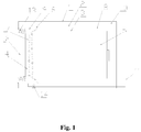
- Fig. 1 is a structural schematic diagram of a drum washing machine of the present disclosure.
- the embodiment provides a cleaning-free drum washing machine, comprising a housing 1, an outer drum 2 and an inner drum 3, wherein the inner drum 3 comprises a hole area 4 which is provided with holes and a hole-free area 5 which is closed; a sealing assembly 6 is arranged between the inner drum on at least one side of the hole area 4 and the outer drum; and a sealed region 8 is defined by the sealing assembly 6, the hole-free area of the inner drum and the outer drum.
- a region between an inner drum and an outer drum can store water and can cause easy accumulation of dirt, and the region cannot be directly cleaned; and the region cannot be thoroughly cleaned by virtue of existing cleaning methods which are time-consuming and labor-consuming.
- the inner drum is locally provided with holes in the drum wall, namely a hole area is defined, and other parts define a closed hole-free area, wherein water intake and drainage can be implemented through holes in the hole area of the inner drum, and the holes can be distributed in one or more circles, so that effective water intake and drainage of the washing machine can be achieved.
- a sealed region between the inner drum and the outer drum is formed, so as to prevent invasion of sewage and to avoid dirt accumulation.
- the sealing assembly is arranged in coordination with the inner drum, so that a region between the hole area and the outer drum and a region between the hole-free area and the outer drum are hermetically separated, and crossed flowing of sewage is prevented.
- the sealing assembly is arranged at one side or two sides of the hole area of the inner drum, so that the sealed region is defined by the sealing assembly, the hole-free area of the inner drum and the outer drum; and the size of the sealed region can be adjusted by setting the positions and number of the sealing assemblies.
- the hole area of the inner drum can be arranged at one side of the inner drum, such as the side close to the laundry input port, and the hole area can also be arranged in the middle of the inner drum; and the position of the sealing assembly is determined in accordance with the position of the hole area.
- the sealing assembly is arranged at the back side of the hole area when the hole area is arranged at the front side of the inner drum, namely the side close to the laundry input port, and the sealed region, which is free from water, is formed between the hole-free area at the middle and back parts of the inner drum and the outer drum.
- the sealing assembly 6 is fixedly arranged on the inner wall of the outer drum 2 and is in dynamic seal with the outer wall of the inner drum 3.
- the sealing assembly can be fixedly arranged on the inner wall of the outer drum in any fixing manner; the sealing assembly is matched with a distance between the inner drum and the outer drum and is in dynamic seal with the outer wall of the inner drum, and sealing can be still achieved under a circumstance that the inner drum is rotated; and in addition, the sealing assembly is convenient to install and is easy to replace.
- the sealing assembly comprises a seal ring and a fixing piece; the seal ring is connected to the inner wall of the outer drum by virtue of the fixing piece; and the fixing piece can be a bolt and the like.
- the seal ring comprises a fixed ring, a connecting part, a dynamic seal ring and a pre-tightening ring.
- the fixed ring is connected to the dynamic seal ring by virtue of the connecting part; the fixed ring, the connecting part and the dynamic seal ring are integrally molded into a whole body; the fixed ring is arranged on the outer circle of the dynamic seal ring and is connected to the inner wall of the outer drum; the inner wall of the dynamic seal ring is in dynamic seal with the outer wall of the inner drum; the pre-tightening ring is arranged on the outer wall of the dynamic seal ring; and the pre-tightening ring is used for implementing pre-tightening of the sealing assembly.
- a water intake and drainage space 9 which is used for implementing water intake and drainage, is defined by the sealing assembly 6, the hole area 4 of the inner drum and the outer drum 2; and the water intake and drainage space 9 is in fluid communication with the interior of the inner drum.
- the sealing assembly is arranged at one side or two sides of the hole area; a water intake and drainage space, which is used for implementing water intake and drainage, can be defined by the sealing assembly, the hole area of the inner drum and the outer drum while the sealed region is formed; and the water intake and drainage space is in fluid communication with the interior of the inner drum through holes of the hole area, so that water intake and drainage of the washing machine can be achieved.
- the sealing assembly can be arranged at the side, away from the laundry input port, of the hole area, so that the water intake and drainage space is defined by a sealing window pad of an observing window, the hole area of the inner drum, the outer drum and the sealing assembly; and the sealed region is defined by the sealing assembly, the hole-free area of the inner drum and the outer drum.
- a water intake pipeline 10 and a drainage pipeline 11 are arranged between the housing 1 and the outer drum 2; and the water intake pipeline 10 and the drainage pipeline 11 communicate with the water intake and drainage space 9.
- the water intake pipeline and the drainage pipeline of the washing machine are arranged between the housing and the outer drum and communicate with the water intake and drainage space which is formed between the inner drum and the outer drum, so that water intake and drainage of the washing machine can be achieved.
- the water intake pipeline and the drainage pipeline can penetrate through the outer drum wall of the water intake and drainage space and be hung in the water intake and drainage space, with openings corresponding to the hole area on the inner drum; openings of the water intake pipeline and the drainage pipeline can also be directly arranged on the outer drum wall on which the water intake and drainage space is formed and correspond to the hole area on the inner drum.
- the water intake and drainage space can be flushed by water which is supplied after drainage; the water intake and drainage space, which is relatively small in volume, is also relatively small in contact area with the inner drum, so that the water intake and drainage space can be thoroughly flushed by water, so as to avoid sewage residues.
- a water outlet of the water intake pipeline 10 is arranged on the outer drum wall of the water intake and drainage space 9 and corresponds to the part, at the upper part of the inner drum, of the hole area 4; and a water inlet of the drainage pipeline 11 is arranged on the outer drum wall of the water intake and drainage space 9 and corresponds to the part, at the lower part of the inner drum, of the hole area 4.
- the water intake pipeline is arranged at the upper end of the washing machine; the water outlet of the water intake pipeline is arranged on the outer drum wall of the water intake and drainage space and corresponds to the part, at the upper part of the inner drum, of the hole area, so that a water flow can enter from the upper end; therefore, clothes can be soaked, and the water intake and drainage space can be flushed by water which is supplied after drainage, so as to remove sewage residues.
- the drainage pipeline is arranged at the lower end of the washing machine; and the water inlet of the drainage pipeline is arranged on the outer drum wall of the water intake and drainage space and corresponds to the part, at the lower part of the inner drum, of the hole area, so as to facilitate collection and discharge of washing water.
- a drainage pump 14 can be arranged on the drainage pipeline, so as to offer power for drainage; or a drainage valve can be arranged, so as to control discharge of water flow.
- the hole area 4 of the inner drum 3 of the embodiment is arranged at the side close to the laundry input port; the sealing assembly 6 is arranged at the side, away from the laundry input port, of the hole area; and the sealed region is defined by the sealing assembly 6, the hole-free area 5 of the inner drum and the outer drum 2.
- the hole area of the inner drum is arranged at the side close to the laundry input port, and other parts define the hole-free area; more preferably, the hole area of the inner drum is arranged at a front flange of the drum body of the drum washing machine; the holes are arranged in one or more circles, so that the sealed region can be defined by the sealing assembly, the hole-free area of the inner drum and the outer drum merely by arranging the sealing assembly at one location at the side, away from the laundry input port, of the hole area. Therefore, a cleaning-free region, which can prevent invasion of sewage, can be formed between a large part of inner drum and the outer drum.
- the water intake and drainage space is defined by the sealing assembly 6, a sealing window pad 13 of an observing window 12 of the washing machine, the hole area 4 of the inner drum and the outer drum 2; and the water intake pipeline 10 and the drainage pipeline 11 of the washing machine communicate with the water intake and drainage space.
- the hole area of the inner drum is arranged at the side close to the laundry input port; preferably, the hole area of the inner drum is arranged at the front flange of the drum body of the drum washing machine; the water intake and drainage space, which is used for implementing water intake and drainage, is defined by a sealing window pad of an observing window of an existing washing machine, the hole area of the inner drum and the sealing assembly at one location. Meanwhile, the water intake pipeline and the drainage pipeline communicate with the water intake and drainage space, so as to implement water intake and drainage.
- a guiding structure by which water is guided from the hole-free area to the hole area, is arranged on the inner surface of the hole-free area of the inner drum.
- a guiding structure such as a guiding groove and the like, is arranged on the hole-free area of the inner drum for guiding water from the hole-free area to the hole area for drainage; and therefore, a drainage effect is enhanced, drainage efficiency is improved and water accumulation is avoided.
- the present disclosure provides a control method of the cleaning-free drum washing machine, wherein the control method at least comprises a washing process, a rinsing process and a dewatering process; during washing process or rinsing process, water, which is supplied, enters the hole-free area 5 from the hole area 4 of the inner drum; and during drainage of the washing machine or drainage of the dewatering process, water enters the hole area 4 from the hole-free area 5.
- water is supplied by the washing machine to flush the water intake and drainage space, so that sewage can be thoroughly flushed away.
- Water intake during washing, the observing window 12 is closed, tap water enters a space between the outer drum and the hole area of the inner drum from the water intake pipeline 10 so as to flush the water intake and drainage space 9, and the water enters the inner drum 3 of the washing machine from the hole area 4 of the inner drum until reaching a proper level; at this moment, no water enters the sealed region 8, and water exists in the water intake and drainage space 9 and the inner drum 3.
- washing and drainage after water intake, the inner drum, which is driven by a motor, is rotated at a certain rotating-stopping ratio so as to conduct washing. After washing, the drainage pump is turned on so as to conduct drainage; and washing water in the inner drum enters the bottom lowest point of the water intake and drainage space through water intake and drainage holes of the hole area 4 and is discharged from the drainage pipeline 11.
- Flushing water is supplied by the washing machine through the water intake pipeline 10 to flush the water intake and drainage space, so as to thoroughly flush away the sewage; and free water is discharged out from the drainage pipeline 11.
- Dewatering the inner drum 3 undergoes dewatering; water is guided to the hole area 4 from the hole-free area 5 of the inner drum through the guiding structure which is arranged on the inner surface of the inner drum 3, the water passes through the lower lowest point of the water intake and drainage space, and enters the drainage pipeline 11 to be discharged.
Landscapes
- Engineering & Computer Science (AREA)
- Textile Engineering (AREA)
- Detail Structures Of Washing Machines And Dryers (AREA)
- Main Body Construction Of Washing Machines And Laundry Dryers (AREA)
- Control Of Washing Machine And Dryer (AREA)
Abstract
Description
- The present disclosure relates to the field of household appliances, and in particular to a drum washing machine and a control method.
- At present, for users, a space between an inner drum and an outer drum of an existing drum washing machine is a sealed region which cannot be directly cleaned. After a period of use of the region, certain dirt will adhere to and be accumulated in the space, and if the dirt is not cleared for a long time, secondary pollution can be caused to clothes in a clothes washing process, which not only results in odor in the washing machine but also brings about the influence on body health due to secondary pollution to washed clothes.
- Currently, the following processing approaches are mainly adopted to clean the inner and outer drums of the washing machines: 1, flushing the inner drums by water flow, so as to reduce dirt adhering to the inner drums; 2, cleaning the washing machines periodically by virtue of tank cleaning agents, so as to remove the dirt; 3,providing a hole-free inner drum in a pulsator washing machine so as to avoid dirt, which cannot avoid dust accumulation between inner and outer drums. However, the approaches have the following shortcomings: water flow flushing is not thorough; it is long in consumed time, time-consuming and labor-consuming and it is high in cost in cleaning with agents; and dirt remains in a space, which serves as a drainage channel, between pulsator hole-free drums.
- As prescribed within Chinese patent of application number
201410215346.3 - In view of this, the present disclosure is provided.
- In order to overcome shortcomings of the prior art, the present disclosure provides a cleaning-free drum washing machine. In the present disclosure, water intake and drainage can be achieved through a hole area of an inner drum of the washing machine, and meanwhile, flushing can be implemented conveniently so as to avoid residues; a hole-free area of the inner drum cooperates with a sealing assembly to form a sealed region between the inner drum and an outer drum so as to avoid crossed flowing of washing sewage and to avoid dirt accumulation between the inner drum and the outer drum; and with the application of the dirt-avoiding washing mode, cleaning-free of the drum washing machine is achieved.
- To solve the technical problem mentioned above, a technical solution as follows is adopted.
- The first object of the disclosure is to provide a drum washing machine, including a housing, an outer drum and an inner drum, wherein the inner drum comprises a hole area which is provided with holes and a hole-free area; a sealing assembly is arranged between the inner drum and the outer drum on at least one side of the hole area; and a sealed region is defined by the sealing assembly, the hole-free area of the inner drum and the outer drum.
- Furthermore, the sealing assembly is fixedly arranged on the inner wall of the outer drum and is in dynamic seal with the outer wall of the inner drum.
- Furthermore, a water intake and drainage space is defined by the sealing assembly, the hole area of the inner drum and the outer drum; and the water intake and drainage space is in fluid communication with the interior of the inner drum.
- Furthermore, a water intake pipeline and a drainage pipeline are arranged between the housing and the outer drum; and the water intake pipeline and the drainage pipeline communicate with the water intake and drainage space.
- Furthermore, a water outlet of the water intake pipeline is arranged on the outer drum wall of the water intake and drainage space and corresponds to the part, at the upper part of the inner drum, of the hole area; a water inlet of the drainage pipeline is arranged on the outer drum wall of the water intake and drainage space and corresponds to the part, at the lower part of the inner drum, of the hole area; and a drainage pump is arranged on the drainage pipeline.
- Furthermore, the hole area is arranged at the side, close to an laundry input port, of the inner drum; the sealing assembly is arranged at the side, away from the laundry input port, of the hole area; and the sealed region is defined by the sealing assembly, the hole-free area of the inner drum and the outer drum.
- Furthermore, the water intake and drainage space is defined by the sealing assembly, a sealing window pad of an observing window of the washing machine, the hole area of the inner drum and the outer drum; and the water intake pipeline and the drainage pipeline of the washing machine communicate with the water intake and drainage space.
- Furthermore, a guiding structure, by which water is guided from the hole-free area to the hole area, is arranged on the inner surface of the hole-free area of the inner drum.
- The second object of the disclosure is to provide a control method for the drum washing machine, which at least comprises a washing process, a rinsing process and a dewatering process, wherein during the washing process or the rinsing process of the washing machine, water, which is supplied, enters the hole-free area from the hole area of the inner drum; and during drainage or the dewatering process of the washing machine, water enters the hole area from the hole-free area.
- Furthermore, after the washing process or rinsing process is completed, water is supplied by the washing machine to flush the water intake and drainage space to thoroughly flush away sewage.
- With the application of the technical solution, the present disclosure, in comparison with the prior art, has the following beneficial effects:
- (1) The inner drum of the washing machine provided by the present disclosure comprises the hole area and the hole-free area, namely the inner drum is merely locally provided with water intake and drainage holes; the hole-free area of the inner drum cooperates with the sealing assembly for effectively separating the inner drum from the outer drum so as to prevent crossed flowing of washing sewage and to avoid dirt accumulation between the inner drum and the outer drum; and therefore, a dirt-avoiding washing mode is achieved.
- (2) Water intake and drainage can be effectively achieved through the hole area of the inner drum of present disclosure; and meanwhile, after drainage of such processes as washing or rinsing, the water intake and drainage space for water intake and drainage can be conveniently flushed, so as to further avoid dirt residues.
- (3) The hole area of the inner drum of the present disclosure is preferably arranged at the front end of the drum body and is close to the laundry input port, so that coordination with a water intake and drainage system of the existing washing machine can be achieved; the inner and outer drums can be separated merely by arranging the sealing assembly at one location; in addition, modification and adding can be implemented on the basis of the existing washing machine; and therefore, the washing machine is low in modification cost and easy to implement.
- The specific embodiments of the disclosure will be further described in detail below in combination with the drawings.
- The drawings, as one part of the present disclosure, are provided for further understanding of the present disclosure; schematic embodiments of the present disclosure and illustrations are used for explaining the present disclosure, but not intended to limit the prevent disclosure. Obviously, the drawings hereinafter are merely some embodiments; and other drawings can be obtained by normal technicians of the field on the basis of the drawings under the precondition of not making creative work.
- In the drawings:
Fig. 1 is a structural schematic diagram of a drum washing machine of the present disclosure. - In the
figure, 1 . housing, 2.outer drum, 3. inner drum, 4. hole area, 5. hole-free area, 6. sealing assembly, 7. water intake and drainage hole, 8. sealed region, 9. water intake and drainage space, 10. water intake pipeline, 11. drainage pipeline, 12. observing window, 13. sealing window pad, and 14. drainage pump. - It is noted that those drawings and text descriptions just explain concept of the present disclosure to technicians of the field by referring to specific embodiments, not aiming at limiting the concept scope of the present disclosure in any forms.
- For clearer understanding of purposes, technical solutions and advantages of the embodiments of the present disclosure, the technical solution in the embodiments is clearly and completely described in the combination with the drawings in the embodiments of the present disclosure; the embodiments hereinafter are used for explaining the present disclosure, not intended to limit the scope of the present disclosure.
- It is noted that in the descriptions of the present disclosure, orientations or positional relations indicated by "up", "down", "front", "rear", "left", "right", "vertical", "inner", "outer" and the like in terms are shown based on the drawings and are only provided for convenient and simplified description of the present disclosure, rather than indicating or implicating that the mentioned device or element must have specific orientations or be constructed or operated in specific orientation, thus being not intended to limit the present disclosure.
- In the descriptions of the present disclosure, it is noted that 'installing', 'connected to' and 'connecting' in the terms are expansive understanding, otherwise clear specifications and limitations, for example, fixed connection, detachable connection or integrated connection, mechanical connection, electrical connection, direct connection or indirect connection through an intermediate. For normal technicians of the field, specific meanings of the terms in the present disclosure can be understood in accordance with specific situations.
- As shown in
Fig. 1 , the embodiment provides a cleaning-free drum washing machine, comprising a housing 1, an outer drum 2 and an inner drum 3, wherein the inner drum 3 comprises a hole area 4 which is provided with holes and a hole-free area 5 which is closed; asealing assembly 6 is arranged between the inner drum on at least one side of the hole area 4 and the outer drum; and a sealed region 8 is defined by thesealing assembly 6, the hole-free area of the inner drum and the outer drum. - In the existing washing machines, a region between an inner drum and an outer drum can store water and can cause easy accumulation of dirt, and the region cannot be directly cleaned; and the region cannot be thoroughly cleaned by virtue of existing cleaning methods which are time-consuming and labor-consuming. While according to the drum washing machine provided by the present disclosure, the inner drum is locally provided with holes in the drum wall, namely a hole area is defined, and other parts define a closed hole-free area, wherein water intake and drainage can be implemented through holes in the hole area of the inner drum, and the holes can be distributed in one or more circles, so that effective water intake and drainage of the washing machine can be achieved. By virtue of the hole-free area of the inner drum, a sealed region between the inner drum and the outer drum is formed, so as to prevent invasion of sewage and to avoid dirt accumulation.
- According to the embodiment, the sealing assembly is arranged in coordination with the inner drum, so that a region between the hole area and the outer drum and a region between the hole-free area and the outer drum are hermetically separated, and crossed flowing of sewage is prevented. The sealing assembly is arranged at one side or two sides of the hole area of the inner drum, so that the sealed region is defined by the sealing assembly, the hole-free area of the inner drum and the outer drum; and the size of the sealed region can be adjusted by setting the positions and number of the sealing assemblies. The hole area of the inner drum can be arranged at one side of the inner drum, such as the side close to the laundry input port, and the hole area can also be arranged in the middle of the inner drum; and the position of the sealing assembly is determined in accordance with the position of the hole area. The sealing assembly is arranged at the back side of the hole area when the hole area is arranged at the front side of the inner drum, namely the side close to the laundry input port, and the sealed region, which is free from water, is formed between the hole-free area at the middle and back parts of the inner drum and the outer drum.
- Furthermore, the sealing
assembly 6 is fixedly arranged on the inner wall of the outer drum 2 and is in dynamic seal with the outer wall of the inner drum 3. - According to the embodiment, the sealing assembly can be fixedly arranged on the inner wall of the outer drum in any fixing manner; the sealing assembly is matched with a distance between the inner drum and the outer drum and is in dynamic seal with the outer wall of the inner drum, and sealing can be still achieved under a circumstance that the inner drum is rotated; and in addition, the sealing assembly is convenient to install and is easy to replace.
- According to the embodiment, the sealing assembly comprises a seal ring and a fixing piece; the seal ring is connected to the inner wall of the outer drum by virtue of the fixing piece; and the fixing piece can be a bolt and the like. The seal ring comprises a fixed ring, a connecting part, a dynamic seal ring and a pre-tightening ring. The fixed ring is connected to the dynamic seal ring by virtue of the connecting part; the fixed ring, the connecting part and the dynamic seal ring are integrally molded into a whole body; the fixed ring is arranged on the outer circle of the dynamic seal ring and is connected to the inner wall of the outer drum; the inner wall of the dynamic seal ring is in dynamic seal with the outer wall of the inner drum; the pre-tightening ring is arranged on the outer wall of the dynamic seal ring; and the pre-tightening ring is used for implementing pre-tightening of the sealing assembly.
- As shown in
Fig. 1 , the embodiment I is further limited; a water intake and drainage space 9, which is used for implementing water intake and drainage, is defined by the sealingassembly 6, the hole area 4 of the inner drum and the outer drum 2; and the water intake and drainage space 9 is in fluid communication with the interior of the inner drum. - The sealing assembly is arranged at one side or two sides of the hole area; a water intake and drainage space, which is used for implementing water intake and drainage, can be defined by the sealing assembly, the hole area of the inner drum and the outer drum while the sealed region is formed; and the water intake and drainage space is in fluid communication with the interior of the inner drum through holes of the hole area, so that water intake and drainage of the washing machine can be achieved. When the hole area is arranged at the side close to the laundry input port, the sealing assembly can be arranged at the side, away from the laundry input port, of the hole area, so that the water intake and drainage space is defined by a sealing window pad of an observing window, the hole area of the inner drum, the outer drum and the sealing assembly; and the sealed region is defined by the sealing assembly, the hole-free area of the inner drum and the outer drum.
- Furthermore, a
water intake pipeline 10 and adrainage pipeline 11 are arranged between the housing 1 and the outer drum 2; and thewater intake pipeline 10 and thedrainage pipeline 11 communicate with the water intake and drainage space 9. - The water intake pipeline and the drainage pipeline of the washing machine are arranged between the housing and the outer drum and communicate with the water intake and drainage space which is formed between the inner drum and the outer drum, so that water intake and drainage of the washing machine can be achieved. The water intake pipeline and the drainage pipeline can penetrate through the outer drum wall of the water intake and drainage space and be hung in the water intake and drainage space, with openings corresponding to the hole area on the inner drum; openings of the water intake pipeline and the drainage pipeline can also be directly arranged on the outer drum wall on which the water intake and drainage space is formed and correspond to the hole area on the inner drum. During washing or rinsing, the water intake and drainage space can be flushed by water which is supplied after drainage; the water intake and drainage space, which is relatively small in volume, is also relatively small in contact area with the inner drum, so that the water intake and drainage space can be thoroughly flushed by water, so as to avoid sewage residues.
- Furthermore, a water outlet of the
water intake pipeline 10 is arranged on the outer drum wall of the water intake and drainage space 9 and corresponds to the part, at the upper part of the inner drum, of the hole area 4; and a water inlet of thedrainage pipeline 11 is arranged on the outer drum wall of the water intake and drainage space 9 and corresponds to the part, at the lower part of the inner drum, of the hole area 4. - The water intake pipeline is arranged at the upper end of the washing machine; the water outlet of the water intake pipeline is arranged on the outer drum wall of the water intake and drainage space and corresponds to the part, at the upper part of the inner drum, of the hole area, so that a water flow can enter from the upper end; therefore, clothes can be soaked, and the water intake and drainage space can be flushed by water which is supplied after drainage, so as to remove sewage residues. The drainage pipeline is arranged at the lower end of the washing machine; and the water inlet of the drainage pipeline is arranged on the outer drum wall of the water intake and drainage space and corresponds to the part, at the lower part of the inner drum, of the hole area, so as to facilitate collection and discharge of washing water.
- A
drainage pump 14 can be arranged on the drainage pipeline, so as to offer power for drainage; or a drainage valve can be arranged, so as to control discharge of water flow. - As shown in
Fig. 1 , the hole area 4 of the inner drum 3 of the embodiment is arranged at the side close to the laundry input port; the sealingassembly 6 is arranged at the side, away from the laundry input port, of the hole area; and the sealed region is defined by the sealingassembly 6, the hole-free area 5 of the inner drum and the outer drum 2. - The hole area of the inner drum is arranged at the side close to the laundry input port, and other parts define the hole-free area; more preferably, the hole area of the inner drum is arranged at a front flange of the drum body of the drum washing machine; the holes are arranged in one or more circles, so that the sealed region can be defined by the sealing assembly, the hole-free area of the inner drum and the outer drum merely by arranging the sealing assembly at one location at the side, away from the laundry input port, of the hole area. Therefore, a cleaning-free region, which can prevent invasion of sewage, can be formed between a large part of inner drum and the outer drum.
- Furthermore, the water intake and drainage space is defined by the sealing
assembly 6, a sealingwindow pad 13 of an observing window 12 of the washing machine, the hole area 4 of the inner drum and the outer drum 2; and thewater intake pipeline 10 and thedrainage pipeline 11 of the washing machine communicate with the water intake and drainage space. - The hole area of the inner drum is arranged at the side close to the laundry input port; preferably, the hole area of the inner drum is arranged at the front flange of the drum body of the drum washing machine; the water intake and drainage space, which is used for implementing water intake and drainage, is defined by a sealing window pad of an observing window of an existing washing machine, the hole area of the inner drum and the sealing assembly at one location. Meanwhile, the water intake pipeline and the drainage pipeline communicate with the water intake and drainage space, so as to implement water intake and drainage. Therefore, coordination with the water intake and drainage system of the existing washing machine can be achieved, and the inner and outer drums can be separated by virtue of the sealing assembly at one location; and modification and adding can be implemented on the basis of the existing clothes washing machine; therefore, the drum washing machine is low in modification cost and easy to implement.
- According to the embodiment, a guiding structure, by which water is guided from the hole-free area to the hole area, is arranged on the inner surface of the hole-free area of the inner drum.
- A guiding structure, such as a guiding groove and the like, is arranged on the hole-free area of the inner drum for guiding water from the hole-free area to the hole area for drainage; and therefore, a drainage effect is enhanced, drainage efficiency is improved and water accumulation is avoided.
- According to the embodiment, the present disclosure provides a control method of the cleaning-free drum washing machine, wherein the control method at least comprises a washing process, a rinsing process and a dewatering process; during washing process or rinsing process, water, which is supplied, enters the hole-free area 5 from the hole area 4 of the inner drum; and during drainage of the washing machine or drainage of the dewatering process, water enters the hole area 4 from the hole-free area 5.
- When the washing process or the rinsing process is started, tap water enters the water intake and drainage space between the outer drum and the hole area of the inner drum from the water intake pipeline, and the water flows into the inner drum from the hole area and enters the hole-free area. When drainage is implemented or the dewatering process is started, water in the inner drum enters the hole area from the hole-free area, or the water, guided by the guiding structure, enters the hole area from the hole-free area, enters the water intake and drainage space at the bottom from the hole area and is discharged from the drainage pipeline. Therefore, effective water intake and drainage of the washing machine can be achieved; meanwhile, invasion of the sewage can be prevented by the sealed region between the large part of inner drum and the outer drum, so that dirt accumulation can be prevented; and cleaning can be avoided.
- Furthermore, after the washing process or the rinsing process is completed, water is supplied by the washing machine to flush the water intake and drainage space, so that sewage can be thoroughly flushed away.
- After drainage of the washing or rinsing process, water is supplied by the washing machine once again so as to flush the water intake and drainage space between the inner drum and the outer drum; and therefore, the residual sewage can be further flushed away and residues can be prevented.
- Washing process is as follows.
- Water intake: during washing, the observing window 12 is closed, tap water enters a space between the outer drum and the hole area of the inner drum from the
water intake pipeline 10 so as to flush the water intake and drainage space 9, and the water enters the inner drum 3 of the washing machine from the hole area 4 of the inner drum until reaching a proper level; at this moment, no water enters the sealed region 8, and water exists in the water intake and drainage space 9 and the inner drum 3. - Washing and drainage: after water intake, the inner drum, which is driven by a motor, is rotated at a certain rotating-stopping ratio so as to conduct washing. After washing, the drainage pump is turned on so as to conduct drainage; and washing water in the inner drum enters the bottom lowest point of the water intake and drainage space through water intake and drainage holes of the hole area 4 and is discharged from the
drainage pipeline 11. - Flushing: water is supplied by the washing machine through the
water intake pipeline 10 to flush the water intake and drainage space, so as to thoroughly flush away the sewage; and free water is discharged out from thedrainage pipeline 11. - Dewatering: the inner drum 3 undergoes dewatering; water is guided to the hole area 4 from the hole-free area 5 of the inner drum through the guiding structure which is arranged on the inner surface of the inner drum 3, the water passes through the lower lowest point of the water intake and drainage space, and enters the
drainage pipeline 11 to be discharged. - Then, the process is repeated until rinsing and washing are completed.
- Obviously, the above-mentioned embodiments are merely preferred embodiments of the disclosure, but not intended to limit the disclosure in any form. Those of ordinary skill in the art can make some changes or modifications to the above-mentioned technical contents into the equivalent embodiments in equivalent variation without departing from the scope of the technical solution of the present disclosure, and contents not departing from the technical solution of the present disclosure and subjected to any simple change, equivalent variation and modification of the above embodiments in accordance with the technical essence of the present disclosure should still fall into the scope of the present disclosure.
Claims (10)
- A drum washing machine, comprising a housing, an outer drum and an inner drum, wherein
the inner drum comprises a hole area provided with holes and a hole-free area;
a sealing assembly is arranged between the inner drum and the outer drum on at least one side of the hole area;
and a sealed region is defined by the sealing assembly, the hole-free area of the inner drum and the outer drum. - The drum washing machine according to claim 1, wherein the sealing assembly is fixedly arranged on an inner wall of the outer drum and is in a dynamic seal with an outer wall of the inner drum.
- The drum washing machine according to claim 1 or 2, wherein a water intake and drainage space is defined by the sealing assembly, the hole area of the inner drum and the outer drum; and
the water intake and drainage space is in communication with an interior of the inner drum. - The drum washing machine according to claim 3, wherein a water intake pipeline and a drainage pipeline are arranged between the housing and the outer drum; and
the water intake pipeline and the drainage pipeline are communicated with the water intake and drainage space. - The drum washing machine according to claim 4, wherein a water outlet of the water intake pipeline is arranged on a wall of the outer drum defining the water intake and drainage space and corresponds to the hole area at an upper part of the inner drum; and
a water inlet of the drainage pipeline is arranged on the wall of the outer drum defining the water intake and drainage space and corresponds to the hole area at a lower part of the inner drum. - The drum washing machine according to claim 1, wherein the hole area of the inner drum is arranged at a side close to an laundry input port;
the sealing assembly is arranged at a side, away from the laundry input port, of the hole area; and
the sealed region is defined by the sealing assembly, the hole-free area of the inner drum and the outer drum. - The drum washing machine according to claim 6, wherein a water intake and drainage space is defined by the sealing assembly, a sealing window pad of an observing window of the washing machine, the hole area of the inner drum and the outer drum; and
the water intake pipeline and the drainage pipeline of the washing machine are communicated with the water intake and drainage space. - The drum washing machine according to any one of claims 1-7, wherein a guiding structure for guiding water from the hole-free area to the hole area, is arranged on an inner surface of the hole-free area of the inner drum.
- A control method of the drum washing machine according to any one of claims 1-8, at least comprising a washing process, a rinsing process and a dewatering process, wherein
during the washing process or the rinsing process of the washing machine, water supplied enters the hole-free area from the hole area of the inner drum; and
during a drainage or the dewatering process of the washing machine, water enters the hole area from the hole-free area. - The control method according to claim 9, wherein after the washing process or rinsing process, water is supplied by the washing machine to flush the water intake and drainage space to thoroughly flush away sewage.
Applications Claiming Priority (2)
| Application Number | Priority Date | Filing Date | Title |
|---|---|---|---|
| CN201610919645.4A CN107974795B (en) | 2016-10-21 | 2016-10-21 | A kind of drum washing machine and control method |
| PCT/CN2017/105611 WO2018072625A1 (en) | 2016-10-21 | 2017-10-11 | Drum washing machine and control method |
Publications (2)
| Publication Number | Publication Date |
|---|---|
| EP3530794A1 true EP3530794A1 (en) | 2019-08-28 |
| EP3530794A4 EP3530794A4 (en) | 2020-06-24 |
Family
ID=62004604
Family Applications (1)
| Application Number | Title | Priority Date | Filing Date |
|---|---|---|---|
| EP17861245.3A Withdrawn EP3530794A4 (en) | 2016-10-21 | 2017-10-11 | DRUM WASHING MACHINE AND CONTROL METHOD |
Country Status (5)
| Country | Link |
|---|---|
| US (1) | US20190264362A1 (en) |
| EP (1) | EP3530794A4 (en) |
| JP (1) | JP2019536512A (en) |
| CN (1) | CN107974795B (en) |
| WO (1) | WO2018072625A1 (en) |
Families Citing this family (17)
| Publication number | Priority date | Publication date | Assignee | Title |
|---|---|---|---|---|
| CN110685113A (en) * | 2018-07-05 | 2020-01-14 | 黄军贤 | Self-cleaning technology of full-automatic drum washing machine |
| CN110952269A (en) * | 2018-09-27 | 2020-04-03 | 青岛海尔滚筒洗衣机有限公司 | Drum washing machine |
| CN111394944A (en) * | 2019-01-02 | 2020-07-10 | 青岛海尔洗衣机有限公司 | Wall-mounted washing machine |
| CN109652947B (en) * | 2019-01-09 | 2021-06-15 | Tcl家用电器(合肥)有限公司 | Drum Assembly and Duplex Washing Machine |
| WO2020256649A1 (en) * | 2019-06-18 | 2020-12-24 | Tulga Simsek | Washing machine motor systems on the drum |
| EP3987111A1 (en) * | 2019-06-18 | 2022-04-27 | Texdreme Arastirma Gelistirme Anonim Sirketi | Indirect heating directly from drum surface |
| EP3987105A1 (en) | 2019-06-18 | 2022-04-27 | Texdreme Arastirma Gelistirme Anonim Sirketi | Washing machine water-free zones of the drum |
| WO2020256651A1 (en) * | 2019-06-18 | 2020-12-24 | Tulga Simsek | Washing machine mechanical balance system with liquid container weights |
| WO2020256655A1 (en) * | 2019-06-18 | 2020-12-24 | Tulga Simsek | Water tub free washing machine |
| WO2020256654A1 (en) * | 2019-06-18 | 2020-12-24 | Tulga Simsek | Washing machine electrical systems on the drum |
| EP3987109A1 (en) * | 2019-06-18 | 2022-04-27 | Texdreme Arastirma Gelistirme Anonim Sirketi | Washing machine mechanical balance system with metal weights |
| WO2020256658A1 (en) * | 2019-06-18 | 2020-12-24 | Tulga Simsek | Washing machine blocking water drain from drum perforations |
| CN112195620B (en) * | 2019-06-19 | 2022-09-23 | 重庆海尔滚筒洗衣机有限公司 | Drum washing machine and control method thereof |
| CN110948741A (en) * | 2019-12-11 | 2020-04-03 | 马阳阳 | Horizontal environmental protection belt cleaning device of old and useless plastic film |
| CN113123078B (en) * | 2020-01-15 | 2023-12-22 | 博西华电器(江苏)有限公司 | Support of washing machine and washing machine |
| WO2023184642A1 (en) * | 2022-03-31 | 2023-10-05 | 无锡小天鹅电器有限公司 | Inner cylinder of clothes treatment device and clothes treatment device |
| CN118223244B (en) * | 2023-10-24 | 2026-01-06 | 无锡美芝电器有限公司 | A garment processing device and its control method and apparatus |
Family Cites Families (15)
| Publication number | Priority date | Publication date | Assignee | Title |
|---|---|---|---|---|
| IT1225855B (en) * | 1988-12-13 | 1990-12-07 | Zanussi A Spa Industrie | Manufacturing process for tubs for washing machines |
| JPH0956977A (en) * | 1995-08-30 | 1997-03-04 | Sharp Corp | Electric washing machine |
| GB2364716A (en) * | 2000-07-12 | 2002-02-06 | Notetry Ltd | Washing machine with water retentive drum |
| US7421865B2 (en) * | 2003-12-18 | 2008-09-09 | Lg Electronics Inc. | Washing machine with drying function and method of controlling the same |
| CN101643994A (en) * | 2009-02-25 | 2010-02-10 | 任文涛 | Self-cleaning device of full-automatic washing machine |
| CN201952646U (en) * | 2011-02-25 | 2011-08-31 | 青岛开世密封工业有限公司 | Washing machine window pad with article storage tank |
| JP2013141508A (en) * | 2012-01-10 | 2013-07-22 | Sharp Corp | Washing machine |
| KR101555758B1 (en) * | 2013-12-20 | 2015-09-25 | 동부대우전자 주식회사 | Washing machine |
| CN104005201B (en) * | 2014-05-21 | 2016-09-14 | 惠而浦(中国)股份有限公司 | Drum washing machine |
| CN204715076U (en) * | 2015-04-09 | 2015-10-21 | 山东小鸭集团家电有限公司 | A kind of washing machine inner tub |
| CN105568616B (en) * | 2016-02-22 | 2018-02-27 | 海信(山东)冰箱有限公司 | A kind of non-porous interior barrel washing machine |
| JP6349334B2 (en) * | 2016-02-26 | 2018-06-27 | 日立アプライアンス株式会社 | Drum washing machine |
| CN107447425B (en) * | 2016-05-31 | 2020-02-07 | 青岛海尔滚筒洗衣机有限公司 | Roller washing machine and cleaning method thereof |
| CN105862318B (en) * | 2016-06-02 | 2017-11-10 | 深圳创新设计研究院有限公司 | Roller washing machine |
| CN105951346B (en) * | 2016-07-08 | 2018-04-13 | 深圳创新设计研究院有限公司 | Roller washing machine |
-
2016
- 2016-10-21 CN CN201610919645.4A patent/CN107974795B/en active Active
-
2017
- 2017-10-11 US US16/343,551 patent/US20190264362A1/en not_active Abandoned
- 2017-10-11 WO PCT/CN2017/105611 patent/WO2018072625A1/en not_active Ceased
- 2017-10-11 JP JP2019520877A patent/JP2019536512A/en active Pending
- 2017-10-11 EP EP17861245.3A patent/EP3530794A4/en not_active Withdrawn
Also Published As
| Publication number | Publication date |
|---|---|
| CN107974795B (en) | 2020-10-13 |
| EP3530794A4 (en) | 2020-06-24 |
| JP2019536512A (en) | 2019-12-19 |
| CN107974795A (en) | 2018-05-01 |
| US20190264362A1 (en) | 2019-08-29 |
| WO2018072625A1 (en) | 2018-04-26 |
Similar Documents
| Publication | Publication Date | Title |
|---|---|---|
| US20190264362A1 (en) | Drum washing machine and control method | |
| CN109957924B (en) | Sewage filtering and recycling device, washing machine and control method | |
| CN105463791B (en) | A kind of washing machine cycles water filtering judgment of clogging processing method | |
| CN104746315B (en) | Washing machine inner tub, washing machine and washing machine line consider filter method to be worth doing | |
| US20180202092A1 (en) | Flocculation washing machine and control method thereof | |
| CN115613306A (en) | Washing machine | |
| CN117248358A (en) | A washing machine and its control method | |
| WO2019114505A1 (en) | Washer capable of automatically adding detergent using negative pressure and laundry washing method thereof | |
| JP6635318B2 (en) | Self-circulating coagulation washing machine and control method | |
| US20240337059A1 (en) | Washing machine and control method thereof | |
| CN112111909B (en) | Drum washing machine | |
| CN210684225U (en) | Washing and steam washing control system of drum washing machine | |
| CN115613302A (en) | Washing machine and control method thereof | |
| CN110592895A (en) | Washing machine drainage system with lint collection | |
| CN108951013B (en) | Thread scrap filtering device and washing machine | |
| CN107227583A (en) | The control method and its device of a kind of washing machine | |
| CN221663228U (en) | Drum washing machine | |
| CN112411120A (en) | A washing machine and control method | |
| CN115613307A (en) | Filter equipment and washing machine | |
| CN219538188U (en) | Sewage tank and floor washing machine | |
| CN115787258B (en) | A washing machine and its control method | |
| CN204601750U (en) | Collect sewage identifying processing clearing machine | |
| CN214655840U (en) | Internal circulation pipeline of energy-saving washing machine | |
| CN209941332U (en) | Washing machine drainage separator | |
| CN216378807U (en) | Washing machine compatible with up-down drainage |
Legal Events
| Date | Code | Title | Description |
|---|---|---|---|
| STAA | Information on the status of an ep patent application or granted ep patent |
Free format text: STATUS: THE INTERNATIONAL PUBLICATION HAS BEEN MADE |
|
| PUAI | Public reference made under article 153(3) epc to a published international application that has entered the european phase |
Free format text: ORIGINAL CODE: 0009012 |
|
| STAA | Information on the status of an ep patent application or granted ep patent |
Free format text: STATUS: REQUEST FOR EXAMINATION WAS MADE |
|
| 17P | Request for examination filed |
Effective date: 20190423 |
|
| AK | Designated contracting states |
Kind code of ref document: A1 Designated state(s): AL AT BE BG CH CY CZ DE DK EE ES FI FR GB GR HR HU IE IS IT LI LT LU LV MC MK MT NL NO PL PT RO RS SE SI SK SM TR |
|
| AX | Request for extension of the european patent |
Extension state: BA ME |
|
| DAV | Request for validation of the european patent (deleted) | ||
| DAX | Request for extension of the european patent (deleted) | ||
| A4 | Supplementary search report drawn up and despatched |
Effective date: 20200526 |
|
| RIC1 | Information provided on ipc code assigned before grant |
Ipc: D06F 37/04 20060101AFI20200518BHEP Ipc: D06F 35/00 20060101ALN20200518BHEP Ipc: D06F 37/26 20060101ALN20200518BHEP Ipc: D06F 39/08 20060101ALN20200518BHEP |
|
| STAA | Information on the status of an ep patent application or granted ep patent |
Free format text: STATUS: THE APPLICATION IS DEEMED TO BE WITHDRAWN |
|
| 18D | Application deemed to be withdrawn |
Effective date: 20210112 |