EP3530778B1 - System and method for recycling fibers from textiles waste - Google Patents
System and method for recycling fibers from textiles waste Download PDFInfo
- Publication number
- EP3530778B1 EP3530778B1 EP19151585.7A EP19151585A EP3530778B1 EP 3530778 B1 EP3530778 B1 EP 3530778B1 EP 19151585 A EP19151585 A EP 19151585A EP 3530778 B1 EP3530778 B1 EP 3530778B1
- Authority
- EP
- European Patent Office
- Prior art keywords
- sanitization
- waste
- color detection
- container
- processing device
- Prior art date
- Legal status (The legal status is an assumption and is not a legal conclusion. Google has not performed a legal analysis and makes no representation as to the accuracy of the status listed.)
- Active
Links
Images

Classifications
-
- D—TEXTILES; PAPER
- D01—NATURAL OR MAN-MADE THREADS OR FIBRES; SPINNING
- D01G—PRELIMINARY TREATMENT OF FIBRES, e.g. FOR SPINNING
- D01G31/00—Warning or safety devices, e.g. automatic fault detectors, stop motions
- D01G31/003—Detection and removal of impurities
-
- B—PERFORMING OPERATIONS; TRANSPORTING
- B09—DISPOSAL OF SOLID WASTE; RECLAMATION OF CONTAMINATED SOIL
- B09B—DISPOSAL OF SOLID WASTE NOT OTHERWISE PROVIDED FOR
- B09B3/00—Destroying solid waste or transforming solid waste into something useful or harmless
-
- D—TEXTILES; PAPER
- D01—NATURAL OR MAN-MADE THREADS OR FIBRES; SPINNING
- D01G—PRELIMINARY TREATMENT OF FIBRES, e.g. FOR SPINNING
- D01G11/00—Disintegrating fibre-containing articles to obtain fibres for re-use
-
- A—HUMAN NECESSITIES
- A61—MEDICAL OR VETERINARY SCIENCE; HYGIENE
- A61L—METHODS OR APPARATUS FOR STERILISING MATERIALS OR OBJECTS IN GENERAL; DISINFECTION, STERILISATION OR DEODORISATION OF AIR; CHEMICAL ASPECTS OF BANDAGES, DRESSINGS, ABSORBENT PADS OR SURGICAL ARTICLES; MATERIALS FOR BANDAGES, DRESSINGS, ABSORBENT PADS OR SURGICAL ARTICLES
- A61L2/00—Disinfection or sterilisation of materials or objects, in general; Accessories therefor
- A61L2/02—Disinfection or sterilisation of materials or objects, in general; Accessories therefor using physical processes
- A61L2/08—Radiation
- A61L2/10—Ultraviolet [UV] radiation
-
- A—HUMAN NECESSITIES
- A61—MEDICAL OR VETERINARY SCIENCE; HYGIENE
- A61L—METHODS OR APPARATUS FOR STERILISING MATERIALS OR OBJECTS IN GENERAL; DISINFECTION, STERILISATION OR DEODORISATION OF AIR; CHEMICAL ASPECTS OF BANDAGES, DRESSINGS, ABSORBENT PADS OR SURGICAL ARTICLES; MATERIALS FOR BANDAGES, DRESSINGS, ABSORBENT PADS OR SURGICAL ARTICLES
- A61L2/00—Disinfection or sterilisation of materials or objects, in general; Accessories therefor
- A61L2/16—Disinfection or sterilisation of materials or objects, in general; Accessories therefor using chemical substances
- A61L2/20—Gaseous substances, e.g. vapours
-
- A—HUMAN NECESSITIES
- A61—MEDICAL OR VETERINARY SCIENCE; HYGIENE
- A61L—METHODS OR APPARATUS FOR STERILISING MATERIALS OR OBJECTS IN GENERAL; DISINFECTION, STERILISATION OR DEODORISATION OF AIR; CHEMICAL ASPECTS OF BANDAGES, DRESSINGS, ABSORBENT PADS OR SURGICAL ARTICLES; MATERIALS FOR BANDAGES, DRESSINGS, ABSORBENT PADS OR SURGICAL ARTICLES
- A61L2/00—Disinfection or sterilisation of materials or objects, in general; Accessories therefor
- A61L2/24—Apparatus using programmed or automatic operation
-
- D—TEXTILES; PAPER
- D01—NATURAL OR MAN-MADE THREADS OR FIBRES; SPINNING
- D01G—PRELIMINARY TREATMENT OF FIBRES, e.g. FOR SPINNING
- D01G11/00—Disintegrating fibre-containing articles to obtain fibres for re-use
- D01G11/04—Opening rags to obtain fibres for re-use
-
- D—TEXTILES; PAPER
- D01—NATURAL OR MAN-MADE THREADS OR FIBRES; SPINNING
- D01G—PRELIMINARY TREATMENT OF FIBRES, e.g. FOR SPINNING
- D01G5/00—Separating, e.g. sorting, fibres
-
- D—TEXTILES; PAPER
- D01—NATURAL OR MAN-MADE THREADS OR FIBRES; SPINNING
- D01G—PRELIMINARY TREATMENT OF FIBRES, e.g. FOR SPINNING
- D01G9/00—Opening or cleaning fibres, e.g. scutching cotton
- D01G9/12—Combinations of opening or cleaning machines
-
- D—TEXTILES; PAPER
- D01—NATURAL OR MAN-MADE THREADS OR FIBRES; SPINNING
- D01G—PRELIMINARY TREATMENT OF FIBRES, e.g. FOR SPINNING
- D01G9/00—Opening or cleaning fibres, e.g. scutching cotton
- D01G9/14—Details of machines or apparatus
-
- D—TEXTILES; PAPER
- D06—TREATMENT OF TEXTILES OR THE LIKE; LAUNDERING; FLEXIBLE MATERIALS NOT OTHERWISE PROVIDED FOR
- D06B—TREATING TEXTILE MATERIALS USING LIQUIDS, GASES OR VAPOURS
- D06B1/00—Applying liquids, gases or vapours onto textile materials to effect treatment, e.g. washing, dyeing, bleaching, sizing or impregnating
- D06B1/02—Applying liquids, gases or vapours onto textile materials to effect treatment, e.g. washing, dyeing, bleaching, sizing or impregnating by spraying or projecting
-
- D—TEXTILES; PAPER
- D06—TREATMENT OF TEXTILES OR THE LIKE; LAUNDERING; FLEXIBLE MATERIALS NOT OTHERWISE PROVIDED FOR
- D06H—MARKING, INSPECTING, SEAMING OR SEVERING TEXTILE MATERIALS
- D06H3/00—Inspecting textile materials
- D06H3/08—Inspecting textile materials by photo-electric or television means
-
- A—HUMAN NECESSITIES
- A61—MEDICAL OR VETERINARY SCIENCE; HYGIENE
- A61L—METHODS OR APPARATUS FOR STERILISING MATERIALS OR OBJECTS IN GENERAL; DISINFECTION, STERILISATION OR DEODORISATION OF AIR; CHEMICAL ASPECTS OF BANDAGES, DRESSINGS, ABSORBENT PADS OR SURGICAL ARTICLES; MATERIALS FOR BANDAGES, DRESSINGS, ABSORBENT PADS OR SURGICAL ARTICLES
- A61L2103/00—Materials or objects being the target of disinfection or sterilisation
- A61L2103/50—Textiles, e.g. bedwear or towels
-
- D—TEXTILES; PAPER
- D01—NATURAL OR MAN-MADE THREADS OR FIBRES; SPINNING
- D01G—PRELIMINARY TREATMENT OF FIBRES, e.g. FOR SPINNING
- D01G15/00—Carding machines or accessories; Card clothing; Burr-crushing or removing arrangements associated with carding or other preliminary-treatment machines
- D01G15/76—Stripping or cleaning carding surfaces; Maintaining cleanliness of carding area
- D01G15/82—Arrangements for confining or removing dust, fly or the like
-
- D—TEXTILES; PAPER
- D04—BRAIDING; LACE-MAKING; KNITTING; TRIMMINGS; NON-WOVEN FABRICS
- D04H—MAKING TEXTILE FABRICS, e.g. FROM FIBRES OR FILAMENTARY MATERIAL; FABRICS MADE BY SUCH PROCESSES OR APPARATUS, e.g. FELTS, NON-WOVEN FABRICS; COTTON-WOOL; WADDING ; NON-WOVEN FABRICS FROM STAPLE FIBRES, FILAMENTS OR YARNS, BONDED WITH AT LEAST ONE WEB-LIKE MATERIAL DURING THEIR CONSOLIDATION
- D04H1/00—Non-woven fabrics formed wholly or mainly of staple fibres or like relatively short fibres
- D04H1/40—Non-woven fabrics formed wholly or mainly of staple fibres or like relatively short fibres from fleeces or layers composed of fibres without existing or potential cohesive properties
- D04H1/42—Non-woven fabrics formed wholly or mainly of staple fibres or like relatively short fibres from fleeces or layers composed of fibres without existing or potential cohesive properties characterised by the use of certain kinds of fibres insofar as this use has no preponderant influence on the consolidation of the fleece
- D04H1/4274—Rags; Fabric scraps
-
- Y—GENERAL TAGGING OF NEW TECHNOLOGICAL DEVELOPMENTS; GENERAL TAGGING OF CROSS-SECTIONAL TECHNOLOGIES SPANNING OVER SEVERAL SECTIONS OF THE IPC; TECHNICAL SUBJECTS COVERED BY FORMER USPC CROSS-REFERENCE ART COLLECTIONS [XRACs] AND DIGESTS
- Y02—TECHNOLOGIES OR APPLICATIONS FOR MITIGATION OR ADAPTATION AGAINST CLIMATE CHANGE
- Y02W—CLIMATE CHANGE MITIGATION TECHNOLOGIES RELATED TO WASTEWATER TREATMENT OR WASTE MANAGEMENT
- Y02W30/00—Technologies for solid waste management
- Y02W30/50—Reuse, recycling or recovery technologies
- Y02W30/66—Disintegrating fibre-containing textile articles to obtain fibres for re-use
Definitions
- the present disclosure relates to the field of fiber recycling, and more specifically, to a system and method for recycling fibers from textiles waste.
- CN-A-107 237 011 discloses a production line for regenerating spinning fibre from general domestic waste textiles comprising a disinfecting device, a sorting device, a cutting device, a button removing device, and a carding device.
- the sorting device comprises several robots for distinguishing the waste in various colours and sorting those out.
- a similar production line is described in CN-A-105 665 299 .
- embodiments of the present disclosure provide a system and method for recycling fibers from textiles waste.
- the technical solutions are as follows.
- a system for recycling fibers from textiles waste includes: a first sanitization device; a pre-processing device; a detection device; a color detection device; a fabric sorting device; a storage device; a fiber processing device; and a second sanitization device mounted in the fiber processing device.
- the first sanitization device, the pre-processing device, the detection device, the color detection device, the fabric sorting device, the storage device and the fiber processing device are sequentially connected along a transmission path of the textiles waste.
- a method for recycling fibers from textiles waste by using the above system includes: initially sanitizing the textiles waste with the first sanitization device; manually removing non-fibrous objects from the sanitized textiles waste at the manual process station of the pre-processing device; detecting pieces attached with metal and removing the pieces attached with metal at the detection device; obtaining a color detection result at the color detecting device and transmitting the color detection result to a robot and an air blower at the fabric sorting device; placing, by the robot and the air blower, the sanitized textiles waste into corresponding category containers according to the color detection result; storing the category containers in the storage device; upon receipt of order from the fiber processing device, transporting the category containers to the fiber processing device; and cutting the sanitized textiles waste from the category containers into smaller pieces for fiber processing, and sanitizing the smaller pieces with the second ultraviolet sanitization device.
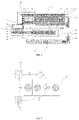
- Fig. 1 is a schematic view of a system for recycling fibers from textiles waste according to an exemplary embodiment.
- the system includes a first sanitization device 100, a pre-processing device 200, a detection device 300, a color detection device 400, a fabric sorting device 500, a storage device 600, a fiber processing device 700 and a second sanitization device 800.
- the first sanitization device 100, the pre-processing device 200, the detection device 300, the color detection device 400, the fabric sorting device 500, the storage device 600 and the fiber processing device 700 are sequentially connected along a transmission path of textiles waste, and the second sanitization device 800 is mounted in the fiber processing device 700.
- the system has two sanitization devices including the first sanitization device 100 and the second sanitization device 800, 90% or more micro-organisms on textiles waste such as used or post-consumer garments can be killed. Further, since the second sanitization device 800 is mounted in the fiber processing device 700, apart from fabric surface, interlayer between fabric surfaces are also sanitized by the first sanitization device 100 and the second sanitization device 800.
- the first sanitization device 100 is a fumigation device.
- the first sanitization device 100 includes an inlet 110, a container 120, a conveyor 130, a fumigation structure 140 and an outlet 150. Referring also to Fig.
- incoming material such as used or post-consumer garments is firstly fed into the container 120 through the inlet 110, then the container 120 loaded with the incoming material is moved by the conveyor 130 to the fumigation structure 140 to perform fumigation operation, and then the container 120 is further moved to the outlet 150 by the conveyor 130, thereby feeding the fumigated material (which has been initially sanitized by the fumigation structure 140 of the first sanitization device 100) to the pre-processing device 200. After that, the empty container 120 is moved by the conveyor 130 back to the inlet 110. In this way, the container 120 is automatically moved in circle by the conveyor 130 as shown in Fig. 2 . Referring to Fig.
- the container 120 is being moved by the conveyor 130 along a path 1->2->3->4->5->6, where 1 represents the inlet 110, 3 represents the fumigation structure 140, 5 represents the outlet 150, and 2, 4 and 6 represent passages, so that the incoming material from the inlet 110 is fumigated in the fumigation structure 140 before being moved to the outlet 150.
- This system allows multiple batches of fumigation to be taken place concurrently.
- Fig. 3 is a schematic enlarged view of the fumigation structure 140 of the first sanitization device 100 shown in Fig. 2 .
- the fumigation structure 140 includes at least one chamber 141, a container cover 143 in each chamber 141, a vacuum line 145, a sanitization gas line 147, a vacuum line valve 149 with a first flexible hose 151 extending through the container cover 143, a sanitization gas line valve 153 with a second flexible hose 155 extending through the container cover 143, a vacuum break valve 157 with a third flexible hose 159 extending through the container cover 143, a pressure gauge 161 mounted in the container cover 143 for detecting pressure in the container 120 when the container 120 is sealed by the container cover 143, and a driving mechanism 163.
- the driving mechanism 163 firstly drives the container cover 143 to move downward (when the fumigation structure 140 is in a position shown in Fig. 3 ) to seal the container 120. Then, the vacuum line valve 149 is turned on, and the sanitization gas line valve 153 and the vacuum break valve 157 are turned off, thereby evacuating the container 120 to a certain vacuum level, e.g., -0.3 barG. After that, the sanitization gas line valve 153 is turned on, and the vacuum line valve 149 and the vacuum break valve 157 are turned off, thereby filling sanitization gas into the container 120 until the pressure in the container 120 is atmospheric pressure and then performing fumigation operation.
- a certain vacuum level e.g., -0.3 barG
- the vacuum line valve 149 is turned on, and the sanitization gas line valve 153 and the vacuum break valve 157 are turned off, thereby evacuating the container 120 to a certain vacuum level, i.e., -0.3 barG.
- the vacuum break valve 157 is turned on, the sanitization gas line valve 153 and the vacuum line valve 149 are turned off, thereby filling air into the container 120 until the pressure in the container 120 is atmospheric pressure.
- the driving mechanism 163 drives the container cover 143 to move upward away from the container 120, and then the fumigated material 900 in the container 120 will be moved to the pre-processing device 200.
- the pre-processing device 200 includes a delivery conveyor 210, a manual processing station 220, a distributor 230, and an indexing conveyor 240.
- the delivery conveyor 210 is adjacent to the output 150 of the first sanitization device 100, so as to receive the fumigated material 900 from the first sanitization device 100.
- non-fibrous objects such as buttons and zips are manually removed, and the fumigated material 900 is transferred from the delivery conveyor 210 to the distributor 230 on the indexing conveyor 240 and then is individually moved towards the detection device 300.
- the detection device 300 such as a metal detection device detects the fumigated material 900 and rejects pieces attached with metal. Then the detected-fumigated material 900 is further individually moved towards the color detection device 400.
- Fig. 4 is a schematic enlarged view of the color detection device 400.
- the color detection device 400 includes a conveyor 410, a conveyor driving motor 420, a motor variable speed driver 430, a light booth 440, a light-booth inlet-output hood 450, a photo sensor 460, a light source 470, a first camera 480 and a second camera 490.
- the conveyor driving motor 420 is connected with the conveyor 410 and is controlled by the motor variable speed driver 430 to drive the conveyor 410 to move along a direction indicated by an arrow shown in Fig. 4 .
- the movement of the conveyor 410 drives the fumigated material 900 to individually move towards the light booth 440.
- the photo sensor 460 may feedback a signal to control the light-booth inlet-output hood 450 to open, thereby allowing the fumigated material 900 to individually move into the light booth 440.
- the light source 470, the first camera 480 and the second camera 490 are disposed in the light booth 440.
- the light source 470 emits light, and the first camera 480 and the second camera 490 receive light reflected by the fumigated material 900, thereby determining color of the fumigated material 900 and then obtaining a color detection result.
- the photo sensor 460 detects the arrival of test subject and triggers camera 480 and 490 to shoot after a certain delay. Positions of the light source 470, the first camera 480 and the second camera 490 are adjusted vertically (when the color detection device 400 is in a position shown in Fig. 4 ), so as to obtain an accurate color detection result.
- the fumigated material 900 is moved out of the light booth 440 and is moved towards the fabric sorting device 500. Meanwhile, the color detection result is transmitted to the fabric sorting device 500.
- the fabric sorting device 500 includes a distributor 510, category containers 520, a robot (not shown) and an air blower (not shown).
- the robot and the air blower receive the color detection result, and then place the fumigated material 900 into corresponding category containers 520 according to the color detection result. Since the fabric sorting device 500 uses the robot and the blower to place sorted fumigated material into category containers 520, thereby eliminating or alleviating the dust problem. Further, the robot of the fabric sorting device 500 receives the color detection result from the color detection device 400 and then automatically places the fumigated material 900 into corresponding category containers 520 according to the color detection result, thus high degree of automation and high accuracy are achieved. When one category container 520 is filled up, the filled category container 520 is transferred by an automated guided vehicle (AGV) 530 along an automated guided vehicle path 540 to the storage device 600.
- AGV automated guided vehicle
- the storage device 600 includes a storage region 610, rows of supporting structures 620 for carrying the category containers 520, a rail 630 between adjacent rows of supporting structures 620, and a cart 640 slidably mounted on the rail 630.
- the cart 640 can automatically store the category containers 520. Upon reception of order from downstream, the cart 640 automatically transports the corresponding category containers 520 to the fiber processing device 700 for production.
- the fiber processing device 700 takes the fumigated material 900 such as color sorted fabrics out of the category containers 520 and cuts them into smaller pieces for fiber processing.
- the fiber processing device 700 includes a feed port 710 and a conveyor 720.
- a dust closure 730 covers the whole fiber processing device 700 except for the feed port 710.
- the fiber processing device 700 may further include a suction nozzle within the dust closure 730 to extract the dust from the operation environment. Since the fumigated material 900 has been color sorted before entering into the fiber processing device 700, subsequent dyeing process and waste water treatment can be eliminated or minimized.
- Fig. 5 is a schematic enlarged view of the fiber processing device 700 with the second sanitization device 800.
- the second sanitization device 800 is an ultraviolet sanitization device which includes UV lighting sources 820.
- the ultraviolet light is an environmentally friendly way to sanitize the fumigated material 900 such as the opened fibers from color sorted fabrics.
- the above description relates to structures of the system for recycling fibers from textiles waste.
- a method for recycling fibers from textiles waste by using the above system for recycling fibers from textiles waste will be described below.
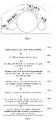
- Fig. 6 is a flow chart showing a method for recycling fibers from textiles waste according to an exemplary embodiment. As shown in Fig. 6 , the method includes the following steps S601-S608.
- the step S601 is to initially sanitize used or post-consumer garments.
- the step S602 is to manually remove non-fibrous objects.
- the step S603 is to detect pieces attached with metal and remove the pieces attached with metal.
- the step S604 is to obtain a color detection result and transmit the color detection result to the robot of the fabric sorting device.
- the step S605 is to place used or post-consumer garments into corresponding category containers 520 according to the color detection result.
- the step S606 is to store the category containers 520 in the storage device.
- the step S607 is to, upon receipt of order from downstream, transport the category containers to the fiber processing device 700 for production.
- the step S608 is to take the used or post-consumer garments such as color sorted fabrics out of the category containers 520 and cut them into smaller pieces for fiber processing, and sanitize the used or post-consumer garments.
- the system and method for recycling fibers from textiles waste according to exemplary embodiments of the present disclosure have following advantages.
- the system includes a first sanitization device 100, which is a sanitization gas fumigation device (Sanitization gas such as Hydrogen Peroxide, Ozone, Ethylene Oxide, etc.) and a second sanitization device 800, which is an ultraviolet sanitization device, 90% or more micro-organisms on textiles waste such as used or post-consumer garments can be killed. Further, since the second sanitization device 800 is mounted in the fiber processing device 700, apart from fabric surface, interlayer between fabric surfaces including the opened fiber structures are also sanitized by the second sanitization device.
- a sanitization gas fumigation device Synitization gas such as Hydrogen Peroxide, Ozone, Ethylene Oxide, etc.
- second sanitization device 800 which is an ultraviolet sanitization device
- the presence of the storage device 600 helps to accumulate the filled category containers 520 so that the filled category containers 520 can be continuously and automatically fed to the fiber processing device 700 to achieve continuous and maximized throughput efficiency.
- the dust closure 730 covers the whole fiber processing device 700 except for the feed port 710, thereby preventing dust or airborne bacteria from spreading to outside of the fiber processing device 700, and then avoiding secondary pollution.
- the fabric sorting device 500 uses the robot and the blower to place sorted material into category containers 520, thereby eliminating or alleviating the dust problem.
- the sliver made from fibers recycled according to the above method by using the above device has adequate physical properties (e.g. good fiber strength and hand feel) for further processing into yarn by spinning, then fabric by knitting or weaving, and then into garments.
Landscapes
- Engineering & Computer Science (AREA)
- Textile Engineering (AREA)
- Health & Medical Sciences (AREA)
- Public Health (AREA)
- Veterinary Medicine (AREA)
- Epidemiology (AREA)
- Life Sciences & Earth Sciences (AREA)
- Animal Behavior & Ethology (AREA)
- General Health & Medical Sciences (AREA)
- Chemical & Material Sciences (AREA)
- Materials Engineering (AREA)
- Chemical Kinetics & Catalysis (AREA)
- General Chemical & Material Sciences (AREA)
- Environmental & Geological Engineering (AREA)
- Processing Of Solid Wastes (AREA)
- Apparatus For Disinfection Or Sterilisation (AREA)
- Sorting Of Articles (AREA)
- Treatment Of Fiber Materials (AREA)
Description
- The present disclosure relates to the field of fiber recycling, and more specifically, to a system and method for recycling fibers from textiles waste.
- Increasing expenses associated with obtaining raw material and constantly increasing consumption of textile products provide a strong economic incentive for developing methods for recycling unused or post-consumer textile material which would otherwise go to waste to be burned or buried. Qualified recycled fibers from the wasted garment/clothing need to be with adequate physical strength and hygienically clean. However, the current methods for recycling unused or post-consumer textile material cannot produce qualified hygienically clean textile fibers from textiles waste such as used or post-consumer garments. Recycled fibers are not pure in color, a dyeing process is thus needed to produce fibers with uniformed color, which means that additional setting of waste water treatment device is needed.
-
CN-A-107 237 011 discloses a production line for regenerating spinning fibre from general domestic waste textiles comprising a disinfecting device, a sorting device, a cutting device, a button removing device, and a carding device. The sorting device comprises several robots for distinguishing the waste in various colours and sorting those out. A similar production line is described inCN-A-105 665 299 . - Further, several steps of the current methods for recycling unused textile material are performed manually, and thus the production efficiency is low.
- In order to overcome the problems existing in the related art, embodiments of the present disclosure provide a system and method for recycling fibers from textiles waste. The technical solutions are as follows.
- According to a first aspect of one embodiment of present disclosure, a system for recycling fibers from textiles waste is provided and includes: a first sanitization device; a pre-processing device; a detection device; a color detection device; a fabric sorting device; a storage device; a fiber processing device; and a second sanitization device mounted in the fiber processing device.
- The first sanitization device, the pre-processing device, the detection device, the color detection device, the fabric sorting device, the storage device and the fiber processing device are sequentially connected along a transmission path of the textiles waste.
- According to a second aspect of one embodiment of present disclosure, a method for recycling fibers from textiles waste by using the above system is provided and includes: initially sanitizing the textiles waste with the first sanitization device; manually removing non-fibrous objects from the sanitized textiles waste at the manual process station of the pre-processing device; detecting pieces attached with metal and removing the pieces attached with metal at the detection device; obtaining a color detection result at the color detecting device and transmitting the color detection result to a robot and an air blower at the fabric sorting device; placing, by the robot and the air blower, the sanitized textiles waste into corresponding category containers according to the color detection result; storing the category containers in the storage device; upon receipt of order from the fiber processing device, transporting the category containers to the fiber processing device; and cutting the sanitized textiles waste from the category containers into smaller pieces for fiber processing, and sanitizing the smaller pieces with the second ultraviolet sanitization device.
- It should be understood that both the foregoing general description and the following detailed description are exemplary and explanatory only and are not restrictive of the disclosure.
- The accompanying drawings, which are incorporated in and constitute a part of this specification, illustrate embodiments consistent with the disclosure and, together with the description, serve to explain the principles of the disclosure.
-
Fig. 1 is a schematic view of a system for recycling fibers from textiles waste according to an exemplary embodiment; -
Fig. 2 is a schematic enlarged view of a first sanitization device which can be applied to the system for recycling fibers from textiles waste shown inFig. 1 according to an exemplary embodiment; -
Fig. 3 is a schematic enlarged view of the fumigation structure of the first sanitization device shown inFig. 2 ; -
Fig. 4 is a schematic enlarged view of a color detection device which can be applied to the system for recycling fibers from textiles waste shown inFig. 1 according to an exemplary embodiment; -
Fig. 5 is a schematic enlarged view of a fiber processing device with a second sanitization device which can be applied to the system for recycling fibers shown inFig. 1 according to an exemplary embodiment; and -
Fig. 6 is a flow chart showing a method for recycling fibers from textiles waste according to an exemplary embodiment. - Reference will now be made in detail to exemplary embodiments, examples of which are illustrated in the accompanying drawings. The following description refers to the accompanying drawings in which the same numbers in different drawings represent the same or similar elements unless otherwise indicated. The implementations set forth in the following description of exemplary embodiments do not represent all implementations consistent with the disclosure. Instead, they are merely examples of devices and methods consistent with aspects related to the disclosure as recited in the appended claims.
-
Fig. 1 is a schematic view of a system for recycling fibers from textiles waste according to an exemplary embodiment. Referring toFig. 1 , the system includes afirst sanitization device 100, apre-processing device 200, adetection device 300, acolor detection device 400, a fabric sorting device 500, a storage device 600, a fiber processing device 700 and asecond sanitization device 800. Thefirst sanitization device 100, thepre-processing device 200, thedetection device 300, thecolor detection device 400, the fabric sorting device 500, the storage device 600 and the fiber processing device 700 are sequentially connected along a transmission path of textiles waste, and thesecond sanitization device 800 is mounted in the fiber processing device 700. Since the system has two sanitization devices including thefirst sanitization device 100 and thesecond sanitization device 800, 90% or more micro-organisms on textiles waste such as used or post-consumer garments can be killed. Further, since thesecond sanitization device 800 is mounted in the fiber processing device 700, apart from fabric surface, interlayer between fabric surfaces are also sanitized by thefirst sanitization device 100 and thesecond sanitization device 800. - Specifically, the
first sanitization device 100 is a fumigation device. In one embodiment as shown inFig. 1 , thefirst sanitization device 100 includes an inlet 110, acontainer 120, aconveyor 130, a fumigation structure 140 and an outlet 150. Referring also toFig. 2 , incoming material such as used or post-consumer garments is firstly fed into thecontainer 120 through the inlet 110, then thecontainer 120 loaded with the incoming material is moved by theconveyor 130 to the fumigation structure 140 to perform fumigation operation, and then thecontainer 120 is further moved to the outlet 150 by theconveyor 130, thereby feeding the fumigated material (which has been initially sanitized by the fumigation structure 140 of the first sanitization device 100) to thepre-processing device 200. After that, theempty container 120 is moved by theconveyor 130 back to the inlet 110. In this way, thecontainer 120 is automatically moved in circle by theconveyor 130 as shown inFig. 2 . Referring toFig. 2 , thecontainer 120 is being moved by theconveyor 130 along a path ①->②->③->④->⑤->⑥, where ① represents the inlet 110, ③ represents the fumigation structure 140, ⑤ represents theoutlet -
Fig. 3 is a schematic enlarged view of the fumigation structure 140 of thefirst sanitization device 100 shown inFig. 2 . Referring toFig. 2 andFig. 3 , the fumigation structure 140 includes at least onechamber 141, acontainer cover 143 in eachchamber 141, a vacuum line 145, a sanitization gas line 147, a vacuum line valve 149 with a first flexible hose 151 extending through thecontainer cover 143, a sanitization gas line valve 153 with a second flexible hose 155 extending through thecontainer cover 143, a vacuum break valve 157 with a third flexible hose 159 extending through thecontainer cover 143, a pressure gauge 161 mounted in thecontainer cover 143 for detecting pressure in thecontainer 120 when thecontainer 120 is sealed by thecontainer cover 143, and a driving mechanism 163. - During the fumigation operation, the driving mechanism 163 firstly drives the
container cover 143 to move downward (when the fumigation structure 140 is in a position shown inFig. 3 ) to seal thecontainer 120. Then, the vacuum line valve 149 is turned on, and the sanitization gas line valve 153 and the vacuum break valve 157 are turned off, thereby evacuating thecontainer 120 to a certain vacuum level, e.g., -0.3 barG. After that, the sanitization gas line valve 153 is turned on, and the vacuum line valve 149 and the vacuum break valve 157 are turned off, thereby filling sanitization gas into thecontainer 120 until the pressure in thecontainer 120 is atmospheric pressure and then performing fumigation operation. Then, the vacuum line valve 149 is turned on, and the sanitization gas line valve 153 and the vacuum break valve 157 are turned off, thereby evacuating thecontainer 120 to a certain vacuum level, i.e., -0.3 barG. After that, the vacuum break valve 157 is turned on, the sanitization gas line valve 153 and the vacuum line valve 149 are turned off, thereby filling air into thecontainer 120 until the pressure in thecontainer 120 is atmospheric pressure. Then, the driving mechanism 163 drives thecontainer cover 143 to move upward away from thecontainer 120, and then the fumigated material 900 in thecontainer 120 will be moved to thepre-processing device 200. - Referring to
Fig. 1 again, thepre-processing device 200 includes adelivery conveyor 210, a manual processing station 220, a distributor 230, and anindexing conveyor 240. Thedelivery conveyor 210 is adjacent to the output 150 of thefirst sanitization device 100, so as to receive the fumigated material 900 from thefirst sanitization device 100. At the manual processing station 220, non-fibrous objects such as buttons and zips are manually removed, and the fumigated material 900 is transferred from thedelivery conveyor 210 to the distributor 230 on the indexingconveyor 240 and then is individually moved towards thedetection device 300. - The
detection device 300 such as a metal detection device detects the fumigated material 900 and rejects pieces attached with metal. Then the detected-fumigated material 900 is further individually moved towards thecolor detection device 400. -
Fig. 4 is a schematic enlarged view of thecolor detection device 400. Thecolor detection device 400 includes aconveyor 410, a conveyor driving motor 420, a motorvariable speed driver 430, a light booth 440, a light-booth inlet-output hood 450, a photo sensor 460, alight source 470, a first camera 480 and a second camera 490. - Specifically, the conveyor driving motor 420 is connected with the
conveyor 410 and is controlled by the motorvariable speed driver 430 to drive theconveyor 410 to move along a direction indicated by an arrow shown inFig. 4 . The movement of theconveyor 410 drives the fumigated material 900 to individually move towards the light booth 440. When the fumigated material 900 is moved to a position detected by the photo sensor 460, the photo sensor 460 may feedback a signal to control the light-booth inlet-output hood 450 to open, thereby allowing the fumigated material 900 to individually move into the light booth 440. Thelight source 470, the first camera 480 and the second camera 490 are disposed in the light booth 440. Thelight source 470 emits light, and the first camera 480 and the second camera 490 receive light reflected by the fumigated material 900, thereby determining color of the fumigated material 900 and then obtaining a color detection result. The photo sensor 460 detects the arrival of test subject and triggers camera 480 and 490 to shoot after a certain delay. Positions of thelight source 470, the first camera 480 and the second camera 490 are adjusted vertically (when thecolor detection device 400 is in a position shown inFig. 4 ), so as to obtain an accurate color detection result. - After the color detection result is obtained, the fumigated material 900 is moved out of the light booth 440 and is moved towards the fabric sorting device 500. Meanwhile, the color detection result is transmitted to the fabric sorting device 500.
- Referring to
Fig. 1 , the fabric sorting device 500 includes a distributor 510, category containers 520, a robot (not shown) and an air blower (not shown). The robot and the air blower receive the color detection result, and then place the fumigated material 900 into corresponding category containers 520 according to the color detection result. Since the fabric sorting device 500 uses the robot and the blower to place sorted fumigated material into category containers 520, thereby eliminating or alleviating the dust problem. Further, the robot of the fabric sorting device 500 receives the color detection result from thecolor detection device 400 and then automatically places the fumigated material 900 into corresponding category containers 520 according to the color detection result, thus high degree of automation and high accuracy are achieved. When one category container 520 is filled up, the filled category container 520 is transferred by an automated guided vehicle (AGV) 530 along an automated guided vehicle path 540 to the storage device 600. - The storage device 600 includes a
storage region 610, rows of supporting structures 620 for carrying the category containers 520, a rail 630 between adjacent rows of supporting structures 620, and a cart 640 slidably mounted on the rail 630. The cart 640 can automatically store the category containers 520. Upon reception of order from downstream, the cart 640 automatically transports the corresponding category containers 520 to the fiber processing device 700 for production. - The fiber processing device 700 takes the fumigated material 900 such as color sorted fabrics out of the category containers 520 and cuts them into smaller pieces for fiber processing. In one embodiment, as shown in
Fig. 1 , the fiber processing device 700 includes a feed port 710 and a conveyor 720. A dust closure 730 covers the whole fiber processing device 700 except for the feed port 710. Further, the fiber processing device 700 may further include a suction nozzle within the dust closure 730 to extract the dust from the operation environment. Since the fumigated material 900 has been color sorted before entering into the fiber processing device 700, subsequent dyeing process and waste water treatment can be eliminated or minimized. -
Fig. 5 is a schematic enlarged view of the fiber processing device 700 with thesecond sanitization device 800. Referring toFig. 1 andFig. 5 , thesecond sanitization device 800 is an ultraviolet sanitization device which includes UV lighting sources 820. The ultraviolet light is an environmentally friendly way to sanitize the fumigated material 900 such as the opened fibers from color sorted fabrics. - The above description relates to structures of the system for recycling fibers from textiles waste. A method for recycling fibers from textiles waste by using the above system for recycling fibers from textiles waste will be described below.
-
Fig. 6 is a flow chart showing a method for recycling fibers from textiles waste according to an exemplary embodiment. As shown inFig. 6 , the method includes the following steps S601-S608. - The step S601 is to initially sanitize used or post-consumer garments.
- The step S602 is to manually remove non-fibrous objects.
- The step S603 is to detect pieces attached with metal and remove the pieces attached with metal.
- The step S604 is to obtain a color detection result and transmit the color detection result to the robot of the fabric sorting device.
- The step S605 is to place used or post-consumer garments into corresponding category containers 520 according to the color detection result.
- The step S606 is to store the category containers 520 in the storage device.
- The step S607 is to, upon receipt of order from downstream, transport the category containers to the fiber processing device 700 for production.
- The step S608 is to take the used or post-consumer garments such as color sorted fabrics out of the category containers 520 and cut them into smaller pieces for fiber processing, and sanitize the used or post-consumer garments.
- The system and method for recycling fibers from textiles waste according to exemplary embodiments of the present disclosure have following advantages.
- Since the system includes a
first sanitization device 100, which is a sanitization gas fumigation device (Sanitization gas such as Hydrogen Peroxide, Ozone, Ethylene Oxide, etc.) and asecond sanitization device 800, which is an ultraviolet sanitization device, 90% or more micro-organisms on textiles waste such as used or post-consumer garments can be killed. Further, since thesecond sanitization device 800 is mounted in the fiber processing device 700, apart from fabric surface, interlayer between fabric surfaces including the opened fiber structures are also sanitized by the second sanitization device. - The presence of the storage device 600 helps to accumulate the filled category containers 520 so that the filled category containers 520 can be continuously and automatically fed to the fiber processing device 700 to achieve continuous and maximized throughput efficiency.
- The dust closure 730 covers the whole fiber processing device 700 except for the feed port 710, thereby preventing dust or airborne bacteria from spreading to outside of the fiber processing device 700, and then avoiding secondary pollution.
- The fabric sorting device 500 uses the robot and the blower to place sorted material into category containers 520, thereby eliminating or alleviating the dust problem.
- The sliver made from fibers recycled according to the above method by using the above device has adequate physical properties (e.g. good fiber strength and hand feel) for further processing into yarn by spinning, then fabric by knitting or weaving, and then into garments.
- It will be appreciated that the present disclosure is not limited to the exact construction that has been described above and illustrated in the accompanying drawings, and that various modifications and changes can be made without departing from the scope thereof.
Claims (11)
- A system for recycling fibers from textiles waste, comprising:a first sanitization device (100), which is a sanitization gas fumigation device for sanitizing the textile waste;a pre-processing device (200) wherein the fumigated textile waste (900) from the first sanitization device (100) is received, and that comprises a manual process station (220) wherein non-fibrous objects are manually removed;a detection device (300), which is configured to detect the fumigated textile waste (900) provided by the first sanitization device (100) and to reject pieces attached with metal;a color detection device (400), which is configured to obtain and transmit a color detection result;a fabric sorting device (500), which includes a distributor (510), category containers (520) and a robot and an air blower,wherein the robot and the air blower are configured to receive the color detection result transmitted by the color detection device (400) and to place the fumigated textile waste (900) into the category containers (520) according to the color detection result;a storage device (600), which is configured to store the category containers (520);a fiber processing device (700), which is configured to take the fumigated textile waste (900) out of the category containers (520) and to cut them into smaller pieces for fibre processing;and a second sanitization device (800), which is an ultraviolet sanitization device (800), mounted in the fiber processing device (700);wherein the first sanitization device (100), the pre-processing device (200), the detection device (300), the color detection device (400), the fabric sorting device (500), the storage device (600) and the fiber processing device (700) are sequentially connected along a transmission path of the textiles waste.
- The system of claim 1, wherein the first sanitization device (100) is a sanitization gas fumigation device using santitization gases selected from the list consisting of hydrogen peroxide, ozone and ethylene oxide.
- The system of claim 2, wherein the first sanitization device (100) includes at least one chamber (141), a container (120) for carrying the textiles waste, a container cover (143) in each chamber, a vacuum line (145), a sanitization gas line (147), a vacuum line valve (149) with a first flexible hose (151) extending through the container cover (143), a sanitization gas line valve (153) with a second flexible hose (155) extending through the container cover (143), a vacuum break valve (157) with a third flexible hose (159) extending through the container cover (143), a pressure gauge (161) mounted in the container cover (143) for detecting pressure in the container (120) when the container (120) is sealed by the container cover (143), and a driving mechanism (163) configured to drive the container cover (143) to seal the container (120) or remove the container cover (143) away from the container (120).
- The system of claim 2, further comprising a dust closure (730) that covers the whole fiber processing device (700).
- The system of claim 4, wherein the fiber processing device (700) further includes a suction nozzle within the dust closure (730).
- The system of claim 1, wherein the color detection device (400) includes:a light booth (440);a conveyor (410) extending through the light booth;a conveyor driving motor (420) connecting with the conveyor;a light-booth inlet-output hood (550);a photo sensor (460) in front of the light-booth inlet-output hood (450) in the transmission path of the textiles waste;a light source (470) disposed in the light booth (440);a first camera (480) disposed in the light booth (440); anda second camera (490) disposed in the light booth (440);wherein the light source (470), the first camera (480) and the second camera (490) cooperate to determining color of the fumigated textile waste (900) and then to obtain the colordetection result.
- The system of claim 6, wherein a vertical position of the light source (470) relative to the light booth (440) is adjustable.
- The system of claim 6, wherein a vertical position of each of the first camera (480) and the second camera (490) relative to the light booth (440) is adjustable.
- The system of claim 6, wherein the color detection device (400) further includes a motor variable speed driver (430).
- The system of claim 1, wherein the storage device (600) includes a storage region (610), rows of supporting structures (620) in the storage region (610) for carrying the category containers (520) of the fabric sorting device (500), a rail (630) between adjacent rows of supporting structures (620), and a cart (640) slidably mounted on the rail (630).
- A method for recycling fibers from textiles waste by using the system of any one of claims 1 to 10, comprising the steps of:initially sanitizing (S601) the textiles waste with the first sanitization device (100);manually removing non-fibrous objects (S602) from the sanitized textiles waste at the manualprocess station (220) of the pre-processing device (200);detecting pieces attached with metal and removing the pieces attached with metal (S603) at the detection device (300);obtaining a color detection result at the color detecting device (400) and transmitting the color detection result to the robot and the air blower (S604) at the fabric sorting device (500); placing (S605), by the robot and the air blower, the sanitized textiles waste into corresponding category containers (520) according to the color detection result;storing (S606) the category containers (520) in the storage device (600); upon receipt of order from the fiber processing device (700), transporting (S607) the category containers (520) to the fiber processing device (700);and cutting (S608) the sanitized textiles waste from the category containers (520) into smaller pieces for fiber processing, and sanitizing the smaller pieces with the second ultraviolet sanitization device (800).
Applications Claiming Priority (1)
| Application Number | Priority Date | Filing Date | Title |
|---|---|---|---|
| US15/877,375 US10458047B2 (en) | 2018-01-22 | 2018-01-22 | System and method for recycling fibers from textiles waste |
Publications (2)
| Publication Number | Publication Date |
|---|---|
| EP3530778A1 EP3530778A1 (en) | 2019-08-28 |
| EP3530778B1 true EP3530778B1 (en) | 2022-04-27 |
Family
ID=65023760
Family Applications (1)
| Application Number | Title | Priority Date | Filing Date |
|---|---|---|---|
| EP19151585.7A Active EP3530778B1 (en) | 2018-01-22 | 2019-01-14 | System and method for recycling fibers from textiles waste |
Country Status (6)
| Country | Link |
|---|---|
| US (1) | US10458047B2 (en) |
| EP (1) | EP3530778B1 (en) |
| JP (1) | JP2019126806A (en) |
| KR (1) | KR102166651B1 (en) |
| CN (2) | CN110064639A (en) |
| TW (1) | TWI683939B (en) |
Families Citing this family (43)
| Publication number | Priority date | Publication date | Assignee | Title |
|---|---|---|---|---|
| US10458047B2 (en) * | 2018-01-22 | 2019-10-29 | Novetex Textiles Limited | System and method for recycling fibers from textiles waste |
| MX2021002716A (en) * | 2018-09-06 | 2021-08-11 | Tompkins Robotics Inc | Parcel and article sorting system and method with destination container removal. |
| CN110191981B (en) * | 2019-03-29 | 2022-05-31 | 香港纺织及成衣研发中心有限公司 | Method and system for garment-to-garment recycling |
| CN111020869A (en) * | 2019-12-27 | 2020-04-17 | 泉州飞鹰无纺布有限责任公司 | Method for preparing flame-retardant non-woven fabric by using waste materials |
| CN111101375B (en) * | 2020-01-03 | 2022-08-23 | 上海韶涵旅游用品制造有限公司 | Method for producing flame-retardant bag by using waste textiles |
| CN111172629B (en) * | 2020-01-21 | 2022-01-21 | 苏州市纤维检验院 | Down feather component and content detection system and down feather quality detection method |
| IT202000015499A1 (en) * | 2020-06-26 | 2021-12-26 | Barbara Biscotti | Use of devices with fan motors for the microbiological sanitization of closed environments |
| CN112442747A (en) * | 2020-11-18 | 2021-03-05 | 颍上鑫鸿纺织科技有限公司 | Method for manufacturing regenerated fiber by using waste textile and regenerated fiber |
| CN112316182B (en) * | 2020-11-24 | 2021-05-28 | 浙江肯特科技股份有限公司 | Waste mask treatment equipment and method |
| CN113668102B (en) * | 2020-12-30 | 2022-08-23 | 苏州多道自动化科技有限公司 | Automatic spinning conveying robot |
| CN113062016B (en) * | 2021-03-12 | 2022-04-15 | 杭州永信纺织有限公司 | Cotton opener |
| KR102501340B1 (en) * | 2021-05-12 | 2023-02-21 | 한국과학기술연구원 | Apparatus for pretreatment of capacitive deionization |
| KR102692291B1 (en) | 2021-11-25 | 2024-08-05 | 허정 | Upcycling system for waste fibers and their operation methods |
| CN114210598B (en) * | 2021-12-14 | 2023-11-28 | 福建永荣锦江股份有限公司 | Chinlon waste silk sorting machine and sorting method thereof |
| US11655397B1 (en) | 2022-06-30 | 2023-05-23 | CreateMe Technologies LLC | Methods of assembling apparel products having cycloalkene adhesives |
| US11712873B1 (en) | 2022-06-30 | 2023-08-01 | CreateMe Technologies LLC | Boronate adhesives for apparel products |
| US11730217B1 (en) | 2022-06-30 | 2023-08-22 | CreateMe Technologies LLC | Methods of disassembling apparel products having cycloalkene adhesives |
| US11752234B1 (en) | 2022-06-30 | 2023-09-12 | CreateMe Technologies LLC | Shape memory adhesives for apparel products |
| US11857013B1 (en) | 2022-06-30 | 2024-01-02 | Createme Technologies Inc. | Methods of assembling apparel products having shape memory adhesives |
| US11730215B1 (en) | 2022-06-30 | 2023-08-22 | CreateMe Technologies LLC | Thioester adhesives for apparel products |
| US11542413B1 (en) | 2022-06-30 | 2023-01-03 | CreateMe Technologies LLC | Methods of disassembling apparel products having imine adhesives |
| US11542412B1 (en) | 2022-06-30 | 2023-01-03 | CreateMe Technologies LLC | Methods of disassembling apparel products having cyclodextrin-azobenzene adhesives |
| US11849791B1 (en) | 2022-06-30 | 2023-12-26 | Createme Technologies Inc. | Methods of assembling apparel products having imine adhesives |
| US11653709B1 (en) | 2022-06-30 | 2023-05-23 | CreateMe Technologies LLC | Methods of disassembling apparel products having disulfide adhesives |
| US11632995B1 (en) | 2022-06-30 | 2023-04-25 | CreateMe Technologies LLC | Methods of assembling apparel products having disulfide adhesives |
| US11634616B1 (en) | 2022-06-30 | 2023-04-25 | CreateMe Technologies LLC | Methods of assembling apparel products having boronate adhesives |
| US11530340B1 (en) | 2022-06-30 | 2022-12-20 | CreateMe Technologies LLC | Cyclodextrin-azobenzene adhesives for apparel products |
| US11692111B1 (en) * | 2022-06-30 | 2023-07-04 | CreateMe Technologies LLC | Methods of disassembling apparel products having shape memory adhesives |
| US11905440B1 (en) | 2022-06-30 | 2024-02-20 | Createme Technologies Inc. | Disulfide adhesives for apparel products |
| US11732159B1 (en) | 2022-06-30 | 2023-08-22 | CreateMe Technologies LLC | Methods of disassembling apparel products having boronate adhesives |
| US11530336B1 (en) | 2022-06-30 | 2022-12-20 | CreateMe Technologies LLC | Methods of assembling apparel products having cyclodextrin-azobenzene adhesives |
| US11713405B1 (en) | 2022-06-30 | 2023-08-01 | CreateMe Technologies LLC | Methods of disassembling apparel products having thioester adhesives |
| US11629272B1 (en) | 2022-06-30 | 2023-04-18 | CreateMe Technologies LLC | Methods of assembling apparel products having thioester adhesives |
| KR20240027240A (en) | 2022-08-23 | 2024-03-04 | 주식회사 플러스앤파트너스 | Manufacturing method of eco-friendly fabric that does not reqire dyeing |
| KR102845209B1 (en) * | 2022-10-07 | 2025-08-13 | 주식회사 엘씨벤쳐스 | Method of recycling waste fiber |
| KR102677624B1 (en) | 2023-02-08 | 2024-06-21 | 이영준 | Manufacturing method for upcycled coating glove using waste fiber, upcycled coating glove manufactured using the same |
| KR102942597B1 (en) | 2023-03-30 | 2026-03-25 | 박진우 | Waste fiber recycled spun yarn, composite yarn including the same and fabric including the same |
| EP4728127A2 (en) * | 2023-06-13 | 2026-04-22 | Looptworks Inc. | Systems for decoloring and recycling pure fibers |
| CN117403353A (en) * | 2023-10-17 | 2024-01-16 | 江苏康溢臣生命科技有限公司 | An opening device for flake production equipment |
| CN118007437B (en) * | 2024-01-24 | 2024-10-11 | 广东润祥精细化学有限公司 | Amino silicone oil softener and preparation method and application thereof |
| DK202430407A1 (en) * | 2024-07-11 | 2026-01-30 | Universal Textile Sorting Aps | Textile recovering system |
| WO2026079473A1 (en) * | 2024-10-09 | 2026-04-16 | 株式会社ワークスタジオ | Method for recycling recovered articles containing fiber waste, resource recycling method generating substantially no waste, method for recycling fiber waste, product, recycled board, thermosetting recycled board, thermoplastic recycled board, moisture-curable recycled board, building material, processed product, and furniture |
| KR20240165897A (en) | 2024-11-06 | 2024-11-25 | 박효은 | Ordering and purchasing system and ordering and purchasing method for daily necessities manufactured through upcycling |
Family Cites Families (25)
| Publication number | Priority date | Publication date | Assignee | Title |
|---|---|---|---|---|
| JPS61234858A (en) * | 1986-03-05 | 1986-10-20 | 株式会社 千代田製作所 | Gas pasturizer |
| JPH0427851A (en) * | 1990-05-23 | 1992-01-30 | Toyobo Co Ltd | Method and apparatus for detecting defect |
| US5471720A (en) * | 1994-01-21 | 1995-12-05 | Burlington Industries, Inc. | Use of at least forty percent recycled denim waste |
| JP3740044B2 (en) * | 2001-09-19 | 2006-01-25 | 株式会社スリーアロー | Storage with sterilizing and deodorizing functions |
| US6637085B2 (en) * | 2001-10-26 | 2003-10-28 | E. I. Du Pont De Nemours And Company | Process for recycling articles containing high-performance fiber |
| KR20030047237A (en) * | 2001-12-08 | 2003-06-18 | 문명곤 | Method for manufacturing a fiber plate utilizing disuse synthetic fibers |
| KR100644099B1 (en) * | 2005-01-05 | 2006-11-10 | 한택환 | Method for manufacturing multipurpose cross-fiber board using waste synthetic fiber |
| KR101158031B1 (en) * | 2009-07-09 | 2012-06-22 | 박중성 | Process for the production of recycled textile goods using the waste fabric material and recycled textile goods make by the same |
| FR2963255B1 (en) * | 2010-07-29 | 2013-10-25 | Cie Continentale Simmons | METHOD FOR RECYCLING FURNITURE, ESPECIALLY SOMMIERS, MATERIAL FLOOR OBTAINED BY SUCH A METHOD, AND ASSOCIATED RECYCLING INSTALLATION |
| US9855682B2 (en) * | 2011-06-10 | 2018-01-02 | Columbia Insurance Company | Methods of recycling synthetic turf, methods of using reclaimed synthetic turf, and products comprising same |
| KR20130137747A (en) * | 2012-06-08 | 2013-12-18 | 이형주 | Method for manufacturing rope from used banner |
| CN102743773B (en) * | 2012-07-19 | 2014-05-21 | 武健 | Ethylene oxide preheating, sterilization and resolution integrated cabinet and sterilizing method |
| CA2933784C (en) | 2014-02-24 | 2020-12-29 | Cnh Industrial Canada, Ltd. | Method to process oilseed flax fiber for use in biocomposite materials |
| KR101513553B1 (en) * | 2014-04-25 | 2015-04-22 | 조선옥 | Manufacturing method of filament using wasted-rope |
| CN204803459U (en) * | 2015-07-08 | 2015-11-25 | 侯林君 | Little metal cleaning device of fibre production facility can be spun in regeneration |
| WO2017011722A1 (en) * | 2015-07-15 | 2017-01-19 | Kimberly-Clark Worldwide, Inc. | Method for clean fiber recovery from contaminated articles |
| CN105562361B (en) * | 2015-12-23 | 2017-12-22 | 西安工程大学 | A kind of autonomous method for sorting of fabric sorting machine people |
| CN105665299A (en) * | 2016-01-25 | 2016-06-15 | 侯林君 | Operation method for automatic sorting unit for waste clothing regeneration spinnable fiber production equipment |
| CN205833650U (en) * | 2016-01-25 | 2016-12-28 | 侯林君 | Waste and old medicated clothing regeneration fiber-spinnable produces the automatic classification sorting unit of equipment |
| JP6505045B2 (en) * | 2016-04-11 | 2019-04-24 | ユニ・チャーム株式会社 | Method of recovering pulp fibers from used absorbent articles |
| CN106000917A (en) * | 2016-07-15 | 2016-10-12 | 安徽东锦资源再生科技有限公司 | Intelligent color sorting device and method for waste fiber products |
| CN106245125B (en) * | 2016-09-12 | 2018-12-11 | 安徽新创智能科技有限公司 | Waste and old clothing environment-friendly high-efficiency regenerative system and regeneration method |
| CN206278768U (en) * | 2016-12-12 | 2017-06-27 | 天津市金宝永来制衣有限公司 | It is a kind of new using the waste and old clothes production special filament yarn winding apparatus of polyster fibre |
| CN107237011B (en) * | 2017-03-09 | 2019-04-30 | 林雁 | General life clothing waste textile regenerated spinnable fiber production line |
| US10458047B2 (en) * | 2018-01-22 | 2019-10-29 | Novetex Textiles Limited | System and method for recycling fibers from textiles waste |
-
2018
- 2018-01-22 US US15/877,375 patent/US10458047B2/en active Active
- 2018-02-07 CN CN201810124897.7A patent/CN110064639A/en active Pending
- 2018-02-07 CN CN201820216886.7U patent/CN208450187U/en active Active
-
2019
- 2019-01-10 KR KR1020190003076A patent/KR102166651B1/en active Active
- 2019-01-14 EP EP19151585.7A patent/EP3530778B1/en active Active
- 2019-01-18 TW TW108101908A patent/TWI683939B/en active
- 2019-01-22 JP JP2019008426A patent/JP2019126806A/en active Pending
Also Published As
| Publication number | Publication date |
|---|---|
| US10458047B2 (en) | 2019-10-29 |
| TWI683939B (en) | 2020-02-01 |
| KR20190089728A (en) | 2019-07-31 |
| TW201932673A (en) | 2019-08-16 |
| CN110064639A (en) | 2019-07-30 |
| US20190226125A1 (en) | 2019-07-25 |
| KR102166651B1 (en) | 2020-10-19 |
| CN208450187U (en) | 2019-02-01 |
| JP2019126806A (en) | 2019-08-01 |
| EP3530778A1 (en) | 2019-08-28 |
Similar Documents
| Publication | Publication Date | Title |
|---|---|---|
| US10458047B2 (en) | System and method for recycling fibers from textiles waste | |
| MX2008012067A (en) | Transporting system for bottles or similar containers, and installation for handling bottles or similar containers. | |
| US11084201B2 (en) | Plant and method for processing plastic preforms with pneumatic conveyor or transport shuttle | |
| CN102820242B (en) | Chip online cleaning and drying equipment | |
| CN107746036A (en) | The full-automatic canning line system of five gallon bottle drummed pure water | |
| SE544165C2 (en) | Waste Sorting Robot | |
| JP2005523858A (en) | Thread suction device | |
| HK40012624B (en) | System and method for recycling fibers from textiles waste | |
| US5626237A (en) | Process for the rapid recognition and filtering out of differently colored foreign bodies in fiber processing lines | |
| HK40012624A (en) | System and method for recycling fibers from textiles waste | |
| US11530496B2 (en) | Spinning machine comprising a plurality of adjacently arranged workstations and a displaceable maintenance unit with a pneumatic working element and method for supplying the pneumatic working element with vacuum | |
| US5749682A (en) | Article collection and distribution system | |
| JP2545998Y2 (en) | Multi-product roving bobbin residual yarn removal device | |
| CN115026000B (en) | Express delivery piece intelligence sorting device that disappears | |
| CN217350692U (en) | Movable vacuumizing cap screwing machine | |
| US4761936A (en) | System for automatically handling roller bottles for cell cultivation | |
| JP3233497U (en) | Weaving line scouring machine with cleaning equipment | |
| CN214289474U (en) | Appearance detection and processing equipment for single-page paper products | |
| US2172509A (en) | Receptacle cleaning machine | |
| CN216397364U (en) | Residual water removing and detecting device of dish washing machine | |
| US3784261A (en) | Article transfer apparatus | |
| CN211825753U (en) | Disposable green articles for use visual inspection system | |
| US3409332A (en) | Apparatus for collecting hosiery | |
| CN110172755A (en) | A kind of cotton cloth processing mixed cotton device | |
| CN107511872B (en) | A kind of cleaning cutoff device of elastic |
Legal Events
| Date | Code | Title | Description |
|---|---|---|---|
| PUAI | Public reference made under article 153(3) epc to a published international application that has entered the european phase |
Free format text: ORIGINAL CODE: 0009012 |
|
| STAA | Information on the status of an ep patent application or granted ep patent |
Free format text: STATUS: REQUEST FOR EXAMINATION WAS MADE |
|
| 17P | Request for examination filed |
Effective date: 20190114 |
|
| AK | Designated contracting states |
Kind code of ref document: A1 Designated state(s): AL AT BE BG CH CY CZ DE DK EE ES FI FR GB GR HR HU IE IS IT LI LT LU LV MC MK MT NL NO PL PT RO RS SE SI SK SM TR |
|
| AX | Request for extension of the european patent |
Extension state: BA ME |
|
| REG | Reference to a national code |
Ref country code: HK Ref legal event code: DE Ref document number: 40012624 Country of ref document: HK |
|
| STAA | Information on the status of an ep patent application or granted ep patent |
Free format text: STATUS: EXAMINATION IS IN PROGRESS |
|
| 17Q | First examination report despatched |
Effective date: 20210826 |
|
| GRAP | Despatch of communication of intention to grant a patent |
Free format text: ORIGINAL CODE: EPIDOSNIGR1 |
|
| STAA | Information on the status of an ep patent application or granted ep patent |
Free format text: STATUS: GRANT OF PATENT IS INTENDED |
|
| INTG | Intention to grant announced |
Effective date: 20220103 |
|
| GRAS | Grant fee paid |
Free format text: ORIGINAL CODE: EPIDOSNIGR3 |
|
| GRAA | (expected) grant |
Free format text: ORIGINAL CODE: 0009210 |
|
| STAA | Information on the status of an ep patent application or granted ep patent |
Free format text: STATUS: THE PATENT HAS BEEN GRANTED |
|
| AK | Designated contracting states |
Kind code of ref document: B1 Designated state(s): AL AT BE BG CH CY CZ DE DK EE ES FI FR GB GR HR HU IE IS IT LI LT LU LV MC MK MT NL NO PL PT RO RS SE SI SK SM TR |
|
| REG | Reference to a national code |
Ref country code: GB Ref legal event code: FG4D |
|
| REG | Reference to a national code |
Ref country code: CH Ref legal event code: EP |
|
| REG | Reference to a national code |
Ref country code: DE Ref legal event code: R096 Ref document number: 602019013999 Country of ref document: DE |
|
| REG | Reference to a national code |
Ref country code: AT Ref legal event code: REF Ref document number: 1486995 Country of ref document: AT Kind code of ref document: T Effective date: 20220515 |
|
| REG | Reference to a national code |
Ref country code: IE Ref legal event code: FG4D |
|
| REG | Reference to a national code |
Ref country code: DE Ref legal event code: R081 Ref document number: 602019013999 Country of ref document: DE Owner name: NOVETEX TEXTILES LIMITED, HK Free format text: FORMER OWNER: NOVETEX TEXTILES LIMITED, KOWLOON, HK |
|
| REG | Reference to a national code |
Ref country code: LT Ref legal event code: MG9D |
|
| REG | Reference to a national code |
Ref country code: NL Ref legal event code: MP Effective date: 20220427 |
|
| REG | Reference to a national code |
Ref country code: AT Ref legal event code: MK05 Ref document number: 1486995 Country of ref document: AT Kind code of ref document: T Effective date: 20220427 |
|
| PG25 | Lapsed in a contracting state [announced via postgrant information from national office to epo] |
Ref country code: NL Free format text: LAPSE BECAUSE OF FAILURE TO SUBMIT A TRANSLATION OF THE DESCRIPTION OR TO PAY THE FEE WITHIN THE PRESCRIBED TIME-LIMIT Effective date: 20220427 |
|
| PG25 | Lapsed in a contracting state [announced via postgrant information from national office to epo] |
Ref country code: SE Free format text: LAPSE BECAUSE OF FAILURE TO SUBMIT A TRANSLATION OF THE DESCRIPTION OR TO PAY THE FEE WITHIN THE PRESCRIBED TIME-LIMIT Effective date: 20220427 Ref country code: PT Free format text: LAPSE BECAUSE OF FAILURE TO SUBMIT A TRANSLATION OF THE DESCRIPTION OR TO PAY THE FEE WITHIN THE PRESCRIBED TIME-LIMIT Effective date: 20220829 Ref country code: NO Free format text: LAPSE BECAUSE OF FAILURE TO SUBMIT A TRANSLATION OF THE DESCRIPTION OR TO PAY THE FEE WITHIN THE PRESCRIBED TIME-LIMIT Effective date: 20220727 Ref country code: LT Free format text: LAPSE BECAUSE OF FAILURE TO SUBMIT A TRANSLATION OF THE DESCRIPTION OR TO PAY THE FEE WITHIN THE PRESCRIBED TIME-LIMIT Effective date: 20220427 Ref country code: HR Free format text: LAPSE BECAUSE OF FAILURE TO SUBMIT A TRANSLATION OF THE DESCRIPTION OR TO PAY THE FEE WITHIN THE PRESCRIBED TIME-LIMIT Effective date: 20220427 Ref country code: GR Free format text: LAPSE BECAUSE OF FAILURE TO SUBMIT A TRANSLATION OF THE DESCRIPTION OR TO PAY THE FEE WITHIN THE PRESCRIBED TIME-LIMIT Effective date: 20220728 Ref country code: FI Free format text: LAPSE BECAUSE OF FAILURE TO SUBMIT A TRANSLATION OF THE DESCRIPTION OR TO PAY THE FEE WITHIN THE PRESCRIBED TIME-LIMIT Effective date: 20220427 Ref country code: ES Free format text: LAPSE BECAUSE OF FAILURE TO SUBMIT A TRANSLATION OF THE DESCRIPTION OR TO PAY THE FEE WITHIN THE PRESCRIBED TIME-LIMIT Effective date: 20220427 Ref country code: BG Free format text: LAPSE BECAUSE OF FAILURE TO SUBMIT A TRANSLATION OF THE DESCRIPTION OR TO PAY THE FEE WITHIN THE PRESCRIBED TIME-LIMIT Effective date: 20220727 Ref country code: AT Free format text: LAPSE BECAUSE OF FAILURE TO SUBMIT A TRANSLATION OF THE DESCRIPTION OR TO PAY THE FEE WITHIN THE PRESCRIBED TIME-LIMIT Effective date: 20220427 |
|
| PG25 | Lapsed in a contracting state [announced via postgrant information from national office to epo] |
Ref country code: RS Free format text: LAPSE BECAUSE OF FAILURE TO SUBMIT A TRANSLATION OF THE DESCRIPTION OR TO PAY THE FEE WITHIN THE PRESCRIBED TIME-LIMIT Effective date: 20220427 Ref country code: PL Free format text: LAPSE BECAUSE OF FAILURE TO SUBMIT A TRANSLATION OF THE DESCRIPTION OR TO PAY THE FEE WITHIN THE PRESCRIBED TIME-LIMIT Effective date: 20220427 Ref country code: LV Free format text: LAPSE BECAUSE OF FAILURE TO SUBMIT A TRANSLATION OF THE DESCRIPTION OR TO PAY THE FEE WITHIN THE PRESCRIBED TIME-LIMIT Effective date: 20220427 Ref country code: IS Free format text: LAPSE BECAUSE OF FAILURE TO SUBMIT A TRANSLATION OF THE DESCRIPTION OR TO PAY THE FEE WITHIN THE PRESCRIBED TIME-LIMIT Effective date: 20220827 |
|
| REG | Reference to a national code |
Ref country code: DE Ref legal event code: R097 Ref document number: 602019013999 Country of ref document: DE |
|
| PG25 | Lapsed in a contracting state [announced via postgrant information from national office to epo] |
Ref country code: SM Free format text: LAPSE BECAUSE OF FAILURE TO SUBMIT A TRANSLATION OF THE DESCRIPTION OR TO PAY THE FEE WITHIN THE PRESCRIBED TIME-LIMIT Effective date: 20220427 Ref country code: SK Free format text: LAPSE BECAUSE OF FAILURE TO SUBMIT A TRANSLATION OF THE DESCRIPTION OR TO PAY THE FEE WITHIN THE PRESCRIBED TIME-LIMIT Effective date: 20220427 Ref country code: RO Free format text: LAPSE BECAUSE OF FAILURE TO SUBMIT A TRANSLATION OF THE DESCRIPTION OR TO PAY THE FEE WITHIN THE PRESCRIBED TIME-LIMIT Effective date: 20220427 Ref country code: EE Free format text: LAPSE BECAUSE OF FAILURE TO SUBMIT A TRANSLATION OF THE DESCRIPTION OR TO PAY THE FEE WITHIN THE PRESCRIBED TIME-LIMIT Effective date: 20220427 Ref country code: DK Free format text: LAPSE BECAUSE OF FAILURE TO SUBMIT A TRANSLATION OF THE DESCRIPTION OR TO PAY THE FEE WITHIN THE PRESCRIBED TIME-LIMIT Effective date: 20220427 Ref country code: CZ Free format text: LAPSE BECAUSE OF FAILURE TO SUBMIT A TRANSLATION OF THE DESCRIPTION OR TO PAY THE FEE WITHIN THE PRESCRIBED TIME-LIMIT Effective date: 20220427 |
|
| PLBE | No opposition filed within time limit |
Free format text: ORIGINAL CODE: 0009261 |
|
| STAA | Information on the status of an ep patent application or granted ep patent |
Free format text: STATUS: NO OPPOSITION FILED WITHIN TIME LIMIT |
|
| PG25 | Lapsed in a contracting state [announced via postgrant information from national office to epo] |
Ref country code: AL Free format text: LAPSE BECAUSE OF FAILURE TO SUBMIT A TRANSLATION OF THE DESCRIPTION OR TO PAY THE FEE WITHIN THE PRESCRIBED TIME-LIMIT Effective date: 20220427 |
|
| 26N | No opposition filed |
Effective date: 20230130 |
|
| PG25 | Lapsed in a contracting state [announced via postgrant information from national office to epo] |
Ref country code: SI Free format text: LAPSE BECAUSE OF FAILURE TO SUBMIT A TRANSLATION OF THE DESCRIPTION OR TO PAY THE FEE WITHIN THE PRESCRIBED TIME-LIMIT Effective date: 20220427 |
|
| P01 | Opt-out of the competence of the unified patent court (upc) registered |
Effective date: 20230529 |
|
| REG | Reference to a national code |
Ref country code: CH Ref legal event code: PL |
|
| PG25 | Lapsed in a contracting state [announced via postgrant information from national office to epo] |
Ref country code: LU Free format text: LAPSE BECAUSE OF NON-PAYMENT OF DUE FEES Effective date: 20230114 |
|
| REG | Reference to a national code |
Ref country code: BE Ref legal event code: MM Effective date: 20230131 |
|
| PG25 | Lapsed in a contracting state [announced via postgrant information from national office to epo] |
Ref country code: LI Free format text: LAPSE BECAUSE OF NON-PAYMENT OF DUE FEES Effective date: 20230131 Ref country code: CH Free format text: LAPSE BECAUSE OF NON-PAYMENT OF DUE FEES Effective date: 20230131 |
|
| PG25 | Lapsed in a contracting state [announced via postgrant information from national office to epo] |
Ref country code: BE Free format text: LAPSE BECAUSE OF NON-PAYMENT OF DUE FEES Effective date: 20230131 |
|
| PG25 | Lapsed in a contracting state [announced via postgrant information from national office to epo] |
Ref country code: IT Free format text: LAPSE BECAUSE OF FAILURE TO SUBMIT A TRANSLATION OF THE DESCRIPTION OR TO PAY THE FEE WITHIN THE PRESCRIBED TIME-LIMIT Effective date: 20220427 Ref country code: IE Free format text: LAPSE BECAUSE OF NON-PAYMENT OF DUE FEES Effective date: 20230114 |
|
| PG25 | Lapsed in a contracting state [announced via postgrant information from national office to epo] |
Ref country code: MC Free format text: LAPSE BECAUSE OF FAILURE TO SUBMIT A TRANSLATION OF THE DESCRIPTION OR TO PAY THE FEE WITHIN THE PRESCRIBED TIME-LIMIT Effective date: 20220427 |
|
| PG25 | Lapsed in a contracting state [announced via postgrant information from national office to epo] |
Ref country code: MC Free format text: LAPSE BECAUSE OF FAILURE TO SUBMIT A TRANSLATION OF THE DESCRIPTION OR TO PAY THE FEE WITHIN THE PRESCRIBED TIME-LIMIT Effective date: 20220427 |
|
| PG25 | Lapsed in a contracting state [announced via postgrant information from national office to epo] |
Ref country code: BG Free format text: LAPSE BECAUSE OF FAILURE TO SUBMIT A TRANSLATION OF THE DESCRIPTION OR TO PAY THE FEE WITHIN THE PRESCRIBED TIME-LIMIT Effective date: 20220427 |
|
| PG25 | Lapsed in a contracting state [announced via postgrant information from national office to epo] |
Ref country code: BG Free format text: LAPSE BECAUSE OF FAILURE TO SUBMIT A TRANSLATION OF THE DESCRIPTION OR TO PAY THE FEE WITHIN THE PRESCRIBED TIME-LIMIT Effective date: 20220427 |
|
| PGFP | Annual fee paid to national office [announced via postgrant information from national office to epo] |
Ref country code: GB Payment date: 20241211 Year of fee payment: 7 |
|
| PGFP | Annual fee paid to national office [announced via postgrant information from national office to epo] |
Ref country code: FR Payment date: 20241223 Year of fee payment: 7 |
|
| PGFP | Annual fee paid to national office [announced via postgrant information from national office to epo] |
Ref country code: DE Payment date: 20241217 Year of fee payment: 7 |
|
| PG25 | Lapsed in a contracting state [announced via postgrant information from national office to epo] |
Ref country code: CY Free format text: LAPSE BECAUSE OF FAILURE TO SUBMIT A TRANSLATION OF THE DESCRIPTION OR TO PAY THE FEE WITHIN THE PRESCRIBED TIME-LIMIT; INVALID AB INITIO Effective date: 20190114 |
|
| PG25 | Lapsed in a contracting state [announced via postgrant information from national office to epo] |
Ref country code: HU Free format text: LAPSE BECAUSE OF FAILURE TO SUBMIT A TRANSLATION OF THE DESCRIPTION OR TO PAY THE FEE WITHIN THE PRESCRIBED TIME-LIMIT; INVALID AB INITIO Effective date: 20190114 |
|
| PG25 | Lapsed in a contracting state [announced via postgrant information from national office to epo] |
Ref country code: TR Free format text: LAPSE BECAUSE OF FAILURE TO SUBMIT A TRANSLATION OF THE DESCRIPTION OR TO PAY THE FEE WITHIN THE PRESCRIBED TIME-LIMIT Effective date: 20220427 |