EP3530542B1 - Expansion device of panels - Google Patents
Expansion device of panels Download PDFInfo
- Publication number
- EP3530542B1 EP3530542B1 EP18159994.5A EP18159994A EP3530542B1 EP 3530542 B1 EP3530542 B1 EP 3530542B1 EP 18159994 A EP18159994 A EP 18159994A EP 3530542 B1 EP3530542 B1 EP 3530542B1
- Authority
- EP
- European Patent Office
- Prior art keywords
- link
- panels
- constituent
- arm member
- members
- Prior art date
- Legal status (The legal status is an assumption and is not a legal conclusion. Google has not performed a legal analysis and makes no representation as to the accuracy of the status listed.)
- Active
Links
Images






Classifications
-
- B—PERFORMING OPERATIONS; TRANSPORTING
- B61—RAILWAYS
- B61D—BODY DETAILS OR KINDS OF RAILWAY VEHICLES
- B61D17/00—Construction details of vehicle bodies
- B61D17/04—Construction details of vehicle bodies with bodies of metal; with composite, e.g. metal and wood body structures
- B61D17/20—Communication passages between coaches; Adaptation of coach ends therefor
- B61D17/22—Communication passages between coaches; Adaptation of coach ends therefor flexible, e.g. bellows
-
- E—FIXED CONSTRUCTIONS
- E04—BUILDING
- E04B—GENERAL BUILDING CONSTRUCTIONS; WALLS, e.g. PARTITIONS; ROOFS; FLOORS; CEILINGS; INSULATION OR OTHER PROTECTION OF BUILDINGS
- E04B2/00—Walls, e.g. partitions, for buildings; Wall construction with regard to insulation; Connections specially adapted to walls
- E04B2/74—Removable non-load-bearing partitions; Partitions with a free upper edge
- E04B2/7407—Removable non-load-bearing partitions; Partitions with a free upper edge assembled using frames with infill panels or coverings only; made-up of panels and a support structure incorporating posts
- E04B2/7416—Removable non-load-bearing partitions; Partitions with a free upper edge assembled using frames with infill panels or coverings only; made-up of panels and a support structure incorporating posts with free upper edge, e.g. for use as office space dividers
- E04B2/7433—Removable non-load-bearing partitions; Partitions with a free upper edge assembled using frames with infill panels or coverings only; made-up of panels and a support structure incorporating posts with free upper edge, e.g. for use as office space dividers with panels and support posts
- E04B2/7438—Removable non-load-bearing partitions; Partitions with a free upper edge assembled using frames with infill panels or coverings only; made-up of panels and a support structure incorporating posts with free upper edge, e.g. for use as office space dividers with panels and support posts with adjustable angular connection of panels to posts
- E04B2/7442—Removable non-load-bearing partitions; Partitions with a free upper edge assembled using frames with infill panels or coverings only; made-up of panels and a support structure incorporating posts with free upper edge, e.g. for use as office space dividers with panels and support posts with adjustable angular connection of panels to posts hinged connections
-
- E—FIXED CONSTRUCTIONS
- E04—BUILDING
- E04B—GENERAL BUILDING CONSTRUCTIONS; WALLS, e.g. PARTITIONS; ROOFS; FLOORS; CEILINGS; INSULATION OR OTHER PROTECTION OF BUILDINGS
- E04B1/00—Constructions in general; Structures which are not restricted either to walls, e.g. partitions, or floors or ceilings or roofs
- E04B1/38—Connections for building structures in general
- E04B1/61—Connections for building structures in general of slab-shaped building elements with each other
- E04B1/6108—Connections for building structures in general of slab-shaped building elements with each other the frontal surfaces of the slabs connected together
- E04B1/612—Connections for building structures in general of slab-shaped building elements with each other the frontal surfaces of the slabs connected together by means between frontal surfaces
- E04B1/6125—Connections for building structures in general of slab-shaped building elements with each other the frontal surfaces of the slabs connected together by means between frontal surfaces with protrusions on the one frontal surface co-operating with recesses in the other frontal surface
- E04B1/6129—Connections for building structures in general of slab-shaped building elements with each other the frontal surfaces of the slabs connected together by means between frontal surfaces with protrusions on the one frontal surface co-operating with recesses in the other frontal surface the connection made by expansion
-
- B—PERFORMING OPERATIONS; TRANSPORTING
- B60—VEHICLES IN GENERAL
- B60D—VEHICLE CONNECTIONS
- B60D5/00—Gangways for coupled vehicles, e.g. of concertina type
-
- B—PERFORMING OPERATIONS; TRANSPORTING
- B61—RAILWAYS
- B61D—BODY DETAILS OR KINDS OF RAILWAY VEHICLES
- B61D17/00—Construction details of vehicle bodies
- B61D17/04—Construction details of vehicle bodies with bodies of metal; with composite, e.g. metal and wood body structures
- B61D17/20—Communication passages between coaches; Adaptation of coach ends therefor
-
- E—FIXED CONSTRUCTIONS
- E04—BUILDING
- E04B—GENERAL BUILDING CONSTRUCTIONS; WALLS, e.g. PARTITIONS; ROOFS; FLOORS; CEILINGS; INSULATION OR OTHER PROTECTION OF BUILDINGS
- E04B1/00—Constructions in general; Structures which are not restricted either to walls, e.g. partitions, or floors or ceilings or roofs
- E04B1/343—Structures characterised by movable, separable, or collapsible parts, e.g. for transport
- E04B1/344—Structures characterised by movable, separable, or collapsible parts, e.g. for transport with hinged parts
- E04B1/3448—Structures characterised by movable, separable, or collapsible parts, e.g. for transport with hinged parts with rotating shell-forming segments
-
- E—FIXED CONSTRUCTIONS
- E04—BUILDING
- E04B—GENERAL BUILDING CONSTRUCTIONS; WALLS, e.g. PARTITIONS; ROOFS; FLOORS; CEILINGS; INSULATION OR OTHER PROTECTION OF BUILDINGS
- E04B1/00—Constructions in general; Structures which are not restricted either to walls, e.g. partitions, or floors or ceilings or roofs
- E04B1/38—Connections for building structures in general
- E04B1/388—Separate connecting elements
-
- E—FIXED CONSTRUCTIONS
- E04—BUILDING
- E04B—GENERAL BUILDING CONSTRUCTIONS; WALLS, e.g. PARTITIONS; ROOFS; FLOORS; CEILINGS; INSULATION OR OTHER PROTECTION OF BUILDINGS
- E04B1/00—Constructions in general; Structures which are not restricted either to walls, e.g. partitions, or floors or ceilings or roofs
- E04B1/38—Connections for building structures in general
- E04B1/61—Connections for building structures in general of slab-shaped building elements with each other
- E04B1/6104—Connections for building structures in general of slab-shaped building elements with each other the overlapping ends of the slabs connected together
-
- G—PHYSICS
- G09—EDUCATION; CRYPTOGRAPHY; DISPLAY; ADVERTISING; SEALS
- G09F—DISPLAYING; ADVERTISING; SIGNS; LABELS OR NAME-PLATES; SEALS
- G09F13/00—Illuminated signs; Luminous advertising
- G09F13/20—Illuminated signs; Luminous advertising with luminescent surfaces or parts
- G09F13/22—Illuminated signs; Luminous advertising with luminescent surfaces or parts electroluminescent
-
- E—FIXED CONSTRUCTIONS
- E04—BUILDING
- E04B—GENERAL BUILDING CONSTRUCTIONS; WALLS, e.g. PARTITIONS; ROOFS; FLOORS; CEILINGS; INSULATION OR OTHER PROTECTION OF BUILDINGS
- E04B1/00—Constructions in general; Structures which are not restricted either to walls, e.g. partitions, or floors or ceilings or roofs
- E04B1/62—Insulation or other protection; Elements or use of specified material therefor
- E04B1/66—Sealings
- E04B1/68—Sealings of joints, e.g. expansion joints
-
- E—FIXED CONSTRUCTIONS
- E04—BUILDING
- E04B—GENERAL BUILDING CONSTRUCTIONS; WALLS, e.g. PARTITIONS; ROOFS; FLOORS; CEILINGS; INSULATION OR OTHER PROTECTION OF BUILDINGS
- E04B1/00—Constructions in general; Structures which are not restricted either to walls, e.g. partitions, or floors or ceilings or roofs
- E04B1/62—Insulation or other protection; Elements or use of specified material therefor
- E04B1/66—Sealings
- E04B1/68—Sealings of joints, e.g. expansion joints
- E04B1/6803—Joint covers
-
- E—FIXED CONSTRUCTIONS
- E04—BUILDING
- E04B—GENERAL BUILDING CONSTRUCTIONS; WALLS, e.g. PARTITIONS; ROOFS; FLOORS; CEILINGS; INSULATION OR OTHER PROTECTION OF BUILDINGS
- E04B1/00—Constructions in general; Structures which are not restricted either to walls, e.g. partitions, or floors or ceilings or roofs
- E04B1/62—Insulation or other protection; Elements or use of specified material therefor
- E04B1/66—Sealings
- E04B1/68—Sealings of joints, e.g. expansion joints
- E04B1/681—Sealings of joints, e.g. expansion joints for free moving parts
Definitions
- the present invention relates to an expansion device of panels.
- An expansion device 101 of panels shown in FIGS. 13 and 14 has been known as a device constituting an inner wall such as a sidewall, an upper wall, or a lower wall of a connecting passage formed inside a hood provided between bodies of rolling stock.
- the document Us 5 515791 A1 discloses such an expansion device.
- the expansion device 101 of panels includes side panels 102, 103 coupled to end surfaces 110a, 111a of bodies 110, 111 that are coupled to each other rotatably around axes 102a, 103a in an up and down direction respectively and a central panel 104 provided on an outer side of the side panels 102, 103 is arranged so as to be positioned in a substantially central portion between the end surfaces 110a, 111a and movable in a direction between the end surfaces 110a, 111a due to a link member 105.
- link member 105 is connected to the outer side of the central panel 104 and also both sides thereof are rotatably connected to axes 1 10b, 111b in the up and down direction provided on the end surfaces 1 10a, 111a of the bodies 110, 111.
- the expansion device 101 of panels constitutes inner walls 114 such as a sidewall, an upper wall, and a lower wall of a connecting passage 113 provided in the bodies 110, 111.
- the length in the direction between the end surfaces 1 10a, 111a of the bodies 110, 111 cannot be made shorter than the length in a state in which inner-side tips of the side panels 102, 103 abut on each other and it is necessary to increase the number of panels to make the length shorter.
- the side panels 102, 103 are rotatably connected to the end surfaces 110a, 111a
- the central panel 104 is connected to the link member 105
- the side panels 102, 103 and the central panel 104 are controlled by different mechanisms and so a problem that it is difficult to increase the number of panels with ease is posed.
- An object of the present invention is to propose an expansion device of panels capable of making shorter the length in a direction of both ends thereof when the length is made the shortest by, compared with an expansion device of panels of the conventional technology, increasing the number of panels.
- the present invention includes a first constituent member configured such that a plurality of panels overlaps and a second constituent member configured such that a plurality of panels overlaps,
- the first link member may include a first main arm member and a second main arm member provided in parallel and may provide a plurality of connecting arm members provided in parallel by rotatably connecting one end of each of the connecting arm members to the second main arm member and the other end thereof to the first main arm member,
- the expansion device of panels may be provided between bodies of rolling stock.
- the present invention includes a first constituent member constructed such that a plurality of panels overlaps and a second constituent member constructed such that a plurality of panels overlaps, in which a first link member that can be expanded and contracted is connected to the first constituent member, a second link member that can be expanded and contracted is connected to the second constituent member, and each of the constituent members can be expanded and contracted by expansion and contraction of each of the link members so that the number of constituent panels can be made larger than that of the conventional technology and also the maximum length between both ends of the expansion device of panels can be made longer and the minimum length thereof can be made shorter.
- first constituent member and the second constituent member can relatively rotate around rotation axes and are removably connected, the first link member and the second link member are connected to both ends of connecting link arm members via a free joint respectively, and the first link member and the second link member can be separated from each other so that even if, for example, an axis in an up and down direction of one body on which the expansion device of panels is mounted and an axis in the up and down direction of the other body are in a distorted positional relation, the expansion device of panels according to the present invention can respond satisfactorily by expanding or contracting.
- the expansion device of panels according to the present invention can suitably be used as constituting at least one of a sidewall, an upper wall, and a lower wall as inner walls of a connecting passage provided between bodies of a vehicle including a plurality of bodies such as rolling stock and a connected bus and in the following embodiments, the description is based on embodiments applied to the sidewall of a connecting passage of rolling stock.
- profile lines are omitted to avoid complication of diagrams.
- FIG. 1 is a top view when an expansion device 1 of panels according to a first embodiment of the present invention is applied as a sidewall 9D of a connecting passage 9C by providing the expansion device 1 between bodies 9A, 9B of rolling stock.
- an A-A direction in FIG. 2 is assumed to be an up and down direction
- a B-B direction to be a direction between end surfaces (horizontal direction) of bodies
- an upper side of FIG. 1 to be an inner side C
- a lower side to be an outer side D.
- the expansion device 1 of panels includes, as shown in FIGS. 1 and 2 , a first constituent member 2 and a second constituent member 3.
- the first constituent member 2 includes, as shown in FIGS. 1 and 2 , three panels of a first panel 4, a second panel 5, and a third panel 6 and these panels are disposed such that at least portions of neighboring panels overlap with each other in the B-B direction (horizontal direction) between end surfaces 9a, 9c of the bodies 9A, 9B.
- the second constituent member 3 includes, as shown in FIGS. 1 and 2 , three panels of a fourth panel 7, a fifth panel 8, and a sixth panel 9 and these panels are disposed such that at least portions of neighboring panels overlap with each other in the B-B direction (horizontal direction) between end surfaces 9a, 9c of the bodies 9A, 9B.
- the first panel 4 is formed such that, as shown in FIGS. 1 to 3 , an inner-side piece 4a and an outer-side piece 4b are formed substantially in parallel by a plate member being bent and also ends on the opposite side of the second panel 5 in the horizontal direction of the inner-side piece 4a and the outer-side piece 4b are connected by a connecting portion 4c so that the cross section thereof is formed in a U-shape and also the second panel 5 side in the horizontal B-B direction and the vertical A-A direction are open. Accordingly, a housing space 4d open on the second panel 5 side and in the vertical A-A direction is formed in the first panel 4. Also, as shown in FIGS. 1 to 3 , a notch 4e that is open only in a front and rear direction and on the second panel 5 side is formed in a vertical portion of the outer-side piece 4b of the first panel 4.
- the second panel 5 is formed such that an inner-side piece 5a and an outer-side piece 5b are formed substantially in parallel by a plate member being bent and also ends on the opposite side of the third panel 6 in the horizontal direction of the inner-side piece 5a and the outer-side piece 5b are connected by a connecting portion 5c so that the cross section thereof is formed in a U-shape and also the third panel 6 side in the horizontal B-B direction and the vertical A-A direction are open. Accordingly, a housing space 5d open on the third panel 6 side and in the vertical A-A direction is formed in the second panel 5. Also, as shown in FIGS. 1 to 3 , a notch 5e that is open only in the front and rear direction and on the third panel 6 side is formed in a vertical portion of the outer-side piece 5b of the second panel 5.
- the second panel 5 is housed, as shown in FIG. 1 , inside the housing space 4d of the first panel 4 in such a way that the third panel 6 side protrudes and also disposed slidably with respect to the first panel 4 in an overlapping direction of panels such as the horizontal B-B direction or the vertical A-A direction.
- the third panel 6 is formed from a plate member, one end thereof in the horizontal B-B direction is connected to the end surface 9a of one body 9A rotatably around a rotation axis 9b in the up and down direction, the other end in the horizontal B-B direction of the third panel 6 is housed inside the housing space 5d of the second panel 5 such that the end surface 9a side protrudes. Also, the third panel 6 is relatively slidably with respect to the second panel 5 in the horizontal B-B direction and the vertical A-A direction.
- the fourth panel 7 is formed, as shown in FIG. 1 , in a structure obtained by horizontally inverting the first panel 4 in the horizontal B-B direction
- the fifth panel 8 is formed in a structure obtained by horizontally inverting the second panel 5 in the horizontal B-B direction
- the sixth panel 9 is formed in a structure obtained by horizontally inverting the third panel 6 in the horizontal B-B direction.
- the fifth panel 8 is housed, as shown in FIG. 1 , inside a housing space 7d of the fourth panel 7 in such a way that the sixth panel 9 side protrudes and also disposed slidably with respect to the fourth panel 7 in the horizontal B-B direction and the vertical A-A direction.
- the other end of the sixth panel 9 is connected to the end surface 9c of the other body 9B rotatably around a rotation axis 9d in the up and down direction and one end in the horizontal B-B direction of the sixth panel 9 is housed inside a housing space 8d of the fifth panel 8 such that the end surface 9c side protrudes.
- the sixth panel 9 is relatively slidably with respect to the fifth panel 8 in an overlapping direction of panels such as the horizontal B-B direction or the vertical A-A direction.
- a columnar member 10 formed like a rectangular column is provided upright, as shown in FIGS. 1 to 3 , between the first constituent member 2 and the second constituent member 3 substantially entirely in the vertical A-A direction.
- the first panel 4 of the first constituent member 2 is perpendicular to the upright direction of the columnar member 10 and also connected rotatably around a rotation axis 11 provided in the horizontal B-B direction.
- the fourth panel 7 of the second constituent member 3 is perpendicular to the upright direction of the columnar member 10 and also connected rotatably around a rotation axis 12 provided in the horizontal B-B direction.
- first constituent member 2 and the second constituent member 3 are perpendicular to the upright direction of the columnar member 10 and also can relatively rotate around the rotation axes 11, 12 provided in the horizontal B-B direction.
- the first constituent member 2 has first link members 14, 14 that can be expanded and contracted connected to an upper portion and a lower portion thereof and the second constituent member 3 has second link members 15, 15 that can be expanded and contracted connected to an upper portion and a lower portion thereof.
- the first link member 14 has, as shown in FIG. 4 , a first main arm member 16 and a second main arm member 17 formed like a long flat plate provided in parallel and the length in the axial direction of the first main arm member 16 is set longer than that in the axial direction of the second main arm member 17.
- a first connecting arm member 18 formed like a long flat plate is connected to the first main arm member 16 rotatably around a rotation axis 19 and, as shown in FIG. 4 , one end 16a of the first main arm member 16 and one end 18a of the first connecting arm member 18 protrude to one side from the rotation axis 19, the other end 16b of the first main arm member 16 and the other end 18b of the first connecting arm member 18 protrude to the other side from the rotation axis 19, and the first main arm member 16 and the first connecting arm member 18 are connected in an X shape. Also, the one end 18a of the first connecting arm member 18 is rotatably connected to the other end 17b of the second main arm member 17.
- One end 20a of a second connecting arm member 20 formed like a long flat plate is connected to one end 17a of the second main arm member 17 rotatably around a rotation axis 21 and the other end 20b thereof is rotatably connected to the one end 16a of the first main arm member 16. Also, the second connecting arm member 20 is provided so as to be parallel to the first connecting arm member 18.
- One end 22a of a third connecting arm member 22 formed like a long flat plate is rotatably connected to the central portion in the axial direction of the second main arm member 17 and the other end 22b thereof is rotatably connected to the central portion between the one end 16a of the first main arm member 16 and the rotation axis 19.
- the third connecting arm member 22 is provided so as to be parallel to the first connecting arm member 18 and the second connecting arm member 20.
- three connecting arm members 18, 20, 22 are provided in parallel between the first main arm member 16 and the second main arm member 17.
- the second connecting arm member 20 may not be provided.
- the first link members 14 constitute a parallel link and can expand a distance L1 between the rotation axis 19 of the first main arm member 16 and the rotation axis 21 of the second main arm member 17, as shown in FIG. 5 , from the state shown in FIG. 4 or contract the distance L1, as shown in FIG. 6 so that the first link member 14 can expand and contract.
- the second link member 15 has a third main arm member 26 and a fourth main arm member 27 formed like a long flat plate provided in parallel and the length in the axial direction of the third main arm member 26 is set substantially the same as that in the axial direction of the fourth main arm member 27.
- One end 28a of a fourth connecting arm member 28 formed like a long flat plate is rotatably connected to one end 27a of a fourth main arm member 27 and the other end 28b thereof is connected to one end 26a of a third main arm member 26 rotatably around a rotation axis 29.
- One end 30a of a fifth connecting arm member 30 formed like a long flat plate is rotatably connected to the other end 26b of the third main arm member 26 and the other end 30b thereof is connected to the other end 27b of the fourth main arm member 27 rotatably around a rotation axis 31. Also, the fifth connecting arm member 30 is provided so as to be parallel to the fourth connecting arm member 28.
- One end 32a of a sixth connecting arm member 32 formed like a long flat plate is rotatably connected to the central portion in the axial direction of the third main arm member 26 and the other end 32b thereof is rotatably connected to the central portion in the axial direction of the fourth main arm member 27.
- the sixth connecting arm member 32 is provided so as to be parallel to the fourth connecting arm member 28 and the fifth connecting arm member 30.
- three connecting arm members 28, 30, 32 are provided in parallel between the third main arm member 26 and the fourth main arm member 27.
- the fifth connecting arm member 30 may not be provided.
- the second link members 15 constitute a parallel link and can expand a distance L2 between the rotation axis 29 of the third main arm member 26 and the rotation axis 31 of the fourth main arm member 27, as shown in FIG. 5 , from the state shown in FIG. 4 or contract the distance L2, as shown in FIG. 6 so that the second link member 15 can expand and contract.
- One end of a first connecting link arm member 34 is connected to the other end 16b of the first main arm member 16 by a free joint capable of rotating in any direction. Also, the central portion in the axial direction of the third main arm member 26 is connected to the other end of the first connecting link arm member 34 by a free joint capable of rotating in any direction.
- One end of a second connecting link arm member 35 is connected to the other end 18b of the first connecting arm member 18 by a free joint capable of rotating in any direction. Also, the central portion in the axial direction of the fourth connecting arm member 28 is connected to the other end of the second connecting link arm member 35 by a free joint capable of rotating in any direction.
- the first connecting link arm member 34 and the second connecting link arm member 35 can each removably be disconnected and connected in the central portion in the axial direction thereof. Also, the expansion device 1 of panels as a whole only requires that three connecting link arm members be provided and one of the first connecting link arm member 34 and the second connecting link arm member 35 of the link members 14, 15 provided in the upper portion and the first connecting link arm member 34 and the second connecting link arm member 35 of the link members 14, 15 provided in the lower portion is not provided. In the present embodiment, as shown in FIG. 2 , the first connecting link arm member 34 is not provided in the link members 14, 15 provided in the lower portion.
- the rotation axis 19 of the first main arm member 16 in the first link member 14 is connected to the first panel 4 via a connecting fitting 36.
- the first link member 14 can rotate clockwise and counterclockwise in FIG. 2 around the rotation axis 19 perpendicular to the upright direction of the first panel 4 and the direction of movement of the members 16, 17, 18, 20, 22 constituting the first link member 14 can be in a parallel positional relation with respect to the outer-side piece 4b of the first panel 4.
- a rotation axis 37 projected so as to be perpendicular to the outer-side piece 5b is disposed in the second panel 5 of the first constituent member 2 so as to be positioned in the notch 4e of the first panel 4 so that, when the first panel 4 slides relative to the second panel 5 in an overlapping direction of panels such as the horizontal B-B direction or the vertical A-A direction, the rotation axis 37 and the first panel 4 will not interfere with each other.
- a connecting hole 22c provided in the central portion in the axial direction of the third connecting arm member 22 is loosely fitted and rotatably connected to the rotation axis 37.
- the rotation axis 37 may be provided in the third connecting arm member 22 to provide the connecting hole 22c in the second panel 5.
- the rotation axis 21 of the second main arm member 17 in the first link member 14 is securely installed on the outer side of an outer-side piece 6b of the third panel 6 in the first constituent member 2 via a connecting fitting 39.
- the panels 4, 5, 6 constituting the first constituent member 2 relatively slide in an overlapping direction of panels (any direction on the paper of FIG. 2 ) such as the horizontal B-B direction or the vertical A-A direction accompanying expansion and contraction of the first link member 14 and rotation around the rotation axis 19 of the first link member 14 so that the first constituent member 2 can expand and contract in any direction of overlapping directions of panels.
- the rotation axis 29 of the third main arm member 26 in the second link member 15 is connected to the fourth panel 7 of the second constituent member 3 via a connecting fitting 41.
- the second link member 15 can rotate clockwise and counterclockwise in FIG. 2 around the rotation axis 29 perpendicular to the upright direction of the fourth panel 7 and the direction of movement of the members 26, 27, 28, 30, 32 constituting the second link member 15 can be in a parallel positional relation with respect to the outer-side piece 7b of the fourth panel 7.
- a rotation axis 43 projected so as to be perpendicular to the outer-side piece 8a is disposed in the fifth panel 8 of the second constituent member 3 so as to be positioned in the notch 7e of the fourth panel 7 so that, when the fifth panel 8 slides relative to the fourth panel 7 in an overlapping direction of panels such as the horizontal B-B direction or the vertical A-A direction, the rotation axis 43 and the fourth panel 7 will not interfere with each other.
- a connecting hole 32c provided in the central portion in the axial direction of the sixth connecting arm member 32 is loosely fitted and rotatably connected to the rotation axis 43.
- the rotation axis 43 may be provided in the sixth connecting arm member 32 to provide the connecting hole 32c in the fifth panel 8.
- the rotation axis 31 of the fifth main arm member 27 in the second link member 15 is securely installed on the outer side of an outer-side piece 9b of the sixth panel 9 via a connecting fitting 45.
- the panels 7, 8, 9 constituting the second constituent member 3 relatively slide in an overlapping direction of panels (any direction on the paper of FIG. 2 ) such as the horizontal B-B direction or the vertical A-A direction accompanying expansion and contraction of the second link member 15 and rotation around the rotation axis 29 of the second link member 15 so that the second constituent member 3 can expand and contract in any direction of overlapping directions of panels.
- the first constituent member 2 and the second constituent member 3 can relatively rotate in a front and rear direction of FIG. 1 around the rotation axes 11, 12, both ends of the first connecting link arm members 34 are connected to each of the first main arm member 16 and the third main arm member 26 via a free joint, and both ends of the second connecting link arm members 35 are connected to each of the first connecting arm member 18 and the fourth connecting arm member 28 via a free joint so that even if the positional relation of an axis in the up and down direction of the one body 9A and an axis in the up and down direction of the other body 9B, the expansion device 1 of panels being mounted between the one body 9A and the other body 9B, is parallel, inclined, distorted, close, or separated, the expansion device 1 of panels can follow and respond to the positional relation.
- the expansion device 1 of panels can respond by the link members 14, 15 being expanded or contracted in the horizontal B-B direction to allow the first constituent member 2 and the second constituent member 3 to expand or contract in the horizontal B-B direction.
- the expansion device 1 of panels can respond by the link members 14, 15 being rotated around the rotation axes 19, 29 to allow panels constituting the first constituent member 2 and the second constituent member 3 to be mutually displaced in the vertical A-A direction.
- the expansion device 1 of panels can respond by only the link members 14, 15 provided in the upper portion or the lower portion being contracted to allow only the upper portion or the lower portion of the first constituent member 2 and the second constituent member 3 to contract in the horizontal B-B direction.
- the expansion device 1 of panels can respond by, for example, the first constituent member 2 and the second constituent member 3 being mutually rotated around the rotation axes 11, 12 and also, as shown in FIG. 7 , the shape of the first link member 14 and that of the second link member 15 being deformed differently and the direction of movement of members constituting the first link member 14 and that of members constituting the second link member 15 being inclined or distorted to allow the movement (deformation) of the first link member 14 and that of the second link member 15 to be linked by the connecting link arm members 34, 35.
- the expansion device 1 of panels can respond regardless of the mutual relative positional relation of the bodies 9A, 9B to which the expansion device 1 of panels is connected.
- the expansion device 1 of panels using six panels 4 to 9, compared with the conventional technology in which three panels 102, 103, 104 are used, the maximum length of the distance between the bodies 9A, 9B can be made longer and the minimum length thereof can be made shorter.
- first constituent member 2 and the second constituent member 3 can easily be separated from each other by separating the central portions in the axial direction of the first connecting link arm member 34 and the second connecting link arm member 35 and disconnecting the columnar member 10 from the first constituent member 2 or the second constituent member 3. Also, the first constituent member 2 and the second constituent member 3 can easily be connected by the reverse operation.
- the first connecting link arm member 34 connects the other end 16b of the first main arm member 16 and the central portion in the axial direction of the third main arm member 26 and the second connecting link arm member 35 connects the other end 18b of the first connecting arm member 18 and the central portion in the axial direction of the fourth connecting arm member 28, but the connecting position of the first connecting link arm member 34 can be set arbitrarily as long as the first main arm member 16 and the third main arm member 26 are connected and the connecting position of the second connecting link arm member 35 can be set arbitrarily as long as the first connecting arm member 18 and the fourth connecting arm member 28 are connected.
- first link members 14 and the second link members 15 can each form a parallel link
- shapes of the first main arm member 16, the third main arm member 26, the first connecting arm member 18, and the fourth connecting arm member 28 are not limited to those described above and can be formed arbitrarily.
- first connecting link arm member 34 and the second connecting link arm member 35 can each separate the first link member 14 and the second link member 15 by removably separating the central portions in the axial direction thereof and in addition, the separation position of the first link member 14 and the second link member 15 can arbitrarily be set.
- the first constituent member 2 and the second constituent member 3 are each constituted using three panels, but the number of constituent panels can be set to any number if the number of panels constituting the first constituent member 2 and that constituting the second constituent member 3 are the same and the number of constituent panels is equal to 2 or greater.
- each of the first constituent member 2 and the second constituent member 3 can be constructed of two panels.
- the first constituent member 2 and that constituting the second constituent member 3 can each be constituted using four panels by increasing the number of connecting arm members provided in parallel with the first connecting arm member 18 between the first main arm member 16 and the second main arm member 17 by one for each of the first constituent member 2 side and the second constituent member 3 side, connecting arm members 50, 51 respectively, and connecting panels 52, 53 having a structure similar to that of the second panel 5 and the fifth panel 8 in the first embodiment to the connecting arm members 50, 51 that have been added.
- the other structure is the same as that of the first embodiment and the description thereof is omitted.
- the columnar member 10 is provided between the first constituent member 2 and the second constituent member 3, but without providing the columnar member 10, the first constituent member 2 and the second constituent member 3 may be mutually rotatably connected by a rotation axis similar to the rotation axes 11, 12 in the central portion in the up and down direction.
- the other structure is the same as that of the first and second embodiments and the description thereof is omitted.
Landscapes
- Engineering & Computer Science (AREA)
- Architecture (AREA)
- Physics & Mathematics (AREA)
- Structural Engineering (AREA)
- Electromagnetism (AREA)
- Civil Engineering (AREA)
- Mechanical Engineering (AREA)
- Wood Science & Technology (AREA)
- Life Sciences & Earth Sciences (AREA)
- Theoretical Computer Science (AREA)
- General Physics & Mathematics (AREA)
- Tents Or Canopies (AREA)
- Manipulator (AREA)
- Pivots And Pivotal Connections (AREA)
- Special Wing (AREA)
- Paper (AREA)
- Dicing (AREA)
Description
- The present invention relates to an expansion device of panels.
- An
expansion device 101 of panels shown inFIGS. 13 and14 has been known as a device constituting an inner wall such as a sidewall, an upper wall, or a lower wall of a connecting passage formed inside a hood provided between bodies of rolling stock. The documentUs 5 515791 A1 discloses such an expansion device. - The
expansion device 101 of panels includesside panels end surfaces bodies axes central panel 104 provided on an outer side of theside panels end surfaces end surfaces link member 105. - Further, the
link member 105 is connected to the outer side of thecentral panel 104 and also both sides thereof are rotatably connected toaxes 1 10b, 111b in the up and down direction provided on theend surfaces 1 10a, 111a of thebodies - Then, the
expansion device 101 of panels constitutesinner walls 114 such as a sidewall, an upper wall, and a lower wall of a connectingpassage 113 provided in thebodies - In the
expansion device 101 of panels in the above conventional technology, the length in the direction between theend surfaces 1 10a, 111a of thebodies side panels side panels end surfaces central panel 104 is connected to thelink member 105, and theside panels central panel 104 are controlled by different mechanisms and so a problem that it is difficult to increase the number of panels with ease is posed. - An object of the present invention is to propose an expansion device of panels capable of making shorter the length in a direction of both ends thereof when the length is made the shortest by, compared with an expansion device of panels of the conventional technology, increasing the number of panels.
- To solve the above problem, the present invention includes a first constituent member configured such that a plurality of panels overlaps and a second constituent member configured such that a plurality of panels overlaps,
- in which a first link member that can be expanded and contracted is connected to the first constituent member, a second link member that can be expanded and contracted is connected to the second constituent member, each of the constituent members can be expanded and contracted by expansion and contraction of each of the link members,
- the first constituent member and the second constituent member can relatively be rotated around rotation axes and also can removably be connected,
- the first link member and the second link member are connected to both ends of connecting link arm members via a free joint respectively, and
- the first link member and the second link member can be separated from each other.
- The first link member may include a first main arm member and a second main arm member provided in parallel and may provide a plurality of connecting arm members provided in parallel by rotatably connecting one end of each of the connecting arm members to the second main arm member and the other end thereof to the first main arm member,
- the second link member may include a third main arm member and a fourth main arm member provided in parallel and may provide a plurality of connecting arm members provided in parallel by rotatably connecting one end of each of the connecting arm members to the fourth main arm member and the other end thereof to the third main arm member,
- a plurality of connecting link arm members may be provided,
- a main arm member in the first link member and a main arm member in the second link member may be connected by one of the connecting link arm members,
- a connecting arm member in the first link member and a connecting arm member in the second link member may be connected by the other of the connecting link arm members,
- panels provided at both ends of the constituent member may be rotatably connected to any main arm members, and
- a panel provided anywhere other than at both ends of the constituent member or one of the connecting arm members may be provided with a rotation axis, to which the other is loosely fitted and connected.
- The expansion device of panels may be provided between bodies of rolling stock.
- The present invention includes a first constituent member constructed such that a plurality of panels overlaps and a second constituent member constructed such that a plurality of panels overlaps, in which a first link member that can be expanded and contracted is connected to the first constituent member, a second link member that can be expanded and contracted is connected to the second constituent member, and each of the constituent members can be expanded and contracted by expansion and contraction of each of the link members so that the number of constituent panels can be made larger than that of the conventional technology and also the maximum length between both ends of the expansion device of panels can be made longer and the minimum length thereof can be made shorter.
- Also, the first constituent member and the second constituent member can relatively rotate around rotation axes and are removably connected, the first link member and the second link member are connected to both ends of connecting link arm members via a free joint respectively, and the first link member and the second link member can be separated from each other so that even if, for example, an axis in an up and down direction of one body on which the expansion device of panels is mounted and an axis in the up and down direction of the other body are in a distorted positional relation, the expansion device of panels according to the present invention can respond satisfactorily by expanding or contracting.
- Other objects, features and advantages of the invention will become apparent from the following description of the embodiments of the invention taken in conjunction with the accompanying drawings.
-
-
FIG. 1 is a top view when an expansion device of panels according to a first embodiment of the present invention is applied as a sidewall of a connecting passage provided between bodies of rolling stock; -
FIG. 2 is a diagram when the expansion device of panels inFIG. 1 is viewed from outside; -
FIG. 3 is an E-E line end view inFIG. 2 ; -
FIG. 4 is a side view of a link member used in the first embodiment of the present invention. -
FIG. 5 is a diagram obtained by expanding in a left and right direction from the state ofFIG. 4 . -
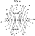
FIG. 6 is a diagram obtained by contracting in the left and right direction from the state ofFIG. 4 ; -
FIG. 7 is a diagram of a state in which an axis in an up and down direction of one body on which the expansion device of panels is mounted and an axis in the up and down direction of the other body are in a distorted positional relation from the state ofFIG. 4 ; -
FIG. 8 is a schematic diagram when an example of the expansion device of panels according to a second embodiment of the present invention is viewed from outside; -
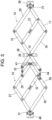
FIG. 9 is a side view of the link member used inFIG. 8 ; -
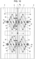
FIG. 10 is a schematic diagram when another example of the expansion device of panels according to the second embodiment of the present invention is viewed from outside; -
FIG. 11 is an end face schematic diagram of an F-F line inFIG. 10 ; -
FIG. 12 is a side view of the link member used inFIG. 10 ; -
FIG. 13 is a cross-sectional view when an expansion device of panels in a conventional technology mounted between bodies is viewed from above; and -
FIG. 14 is a view when the expansion device of panels inFIG. 13 is viewed from outside. - The expansion device of panels according to the present invention can suitably be used as constituting at least one of a sidewall, an upper wall, and a lower wall as inner walls of a connecting passage provided between bodies of a vehicle including a plurality of bodies such as rolling stock and a connected bus and in the following embodiments, the description is based on embodiments applied to the sidewall of a connecting passage of rolling stock. In the diagrams, profile lines are omitted to avoid complication of diagrams.
-
FIG. 1 is a top view when anexpansion device 1 of panels according to a first embodiment of the present invention is applied as asidewall 9D of a connectingpassage 9C by providing theexpansion device 1 betweenbodies FIG. 2 is assumed to be an up and down direction, a B-B direction to be a direction between end surfaces (horizontal direction) of bodies, an upper side ofFIG. 1 to be an inner side C, and a lower side to be an outer side D. - The
expansion device 1 of panels includes, as shown inFIGS. 1 and2 , a firstconstituent member 2 and asecond constituent member 3. - The first
constituent member 2 includes, as shown inFIGS. 1 and2 , three panels of afirst panel 4, asecond panel 5, and athird panel 6 and these panels are disposed such that at least portions of neighboring panels overlap with each other in the B-B direction (horizontal direction) betweenend surfaces bodies second constituent member 3 includes, as shown inFIGS. 1 and2 , three panels of afourth panel 7, afifth panel 8, and asixth panel 9 and these panels are disposed such that at least portions of neighboring panels overlap with each other in the B-B direction (horizontal direction) betweenend surfaces bodies - The
first panel 4 is formed such that, as shown inFIGS. 1 to 3 , an inner-side piece 4a and an outer-side piece 4b are formed substantially in parallel by a plate member being bent and also ends on the opposite side of thesecond panel 5 in the horizontal direction of the inner-side piece 4a and the outer-side piece 4b are connected by a connectingportion 4c so that the cross section thereof is formed in a U-shape and also thesecond panel 5 side in the horizontal B-B direction and the vertical A-A direction are open. Accordingly, ahousing space 4d open on thesecond panel 5 side and in the vertical A-A direction is formed in thefirst panel 4. Also, as shown inFIGS. 1 to 3 , anotch 4e that is open only in a front and rear direction and on thesecond panel 5 side is formed in a vertical portion of the outer-side piece 4b of thefirst panel 4. - The
second panel 5 is formed such that an inner-side piece 5a and an outer-side piece 5b are formed substantially in parallel by a plate member being bent and also ends on the opposite side of thethird panel 6 in the horizontal direction of the inner-side piece 5a and the outer-side piece 5b are connected by a connectingportion 5c so that the cross section thereof is formed in a U-shape and also thethird panel 6 side in the horizontal B-B direction and the vertical A-A direction are open. Accordingly, ahousing space 5d open on thethird panel 6 side and in the vertical A-A direction is formed in thesecond panel 5. Also, as shown inFIGS. 1 to 3 , anotch 5e that is open only in the front and rear direction and on thethird panel 6 side is formed in a vertical portion of the outer-side piece 5b of thesecond panel 5. - The
second panel 5 is housed, as shown inFIG. 1 , inside thehousing space 4d of thefirst panel 4 in such a way that thethird panel 6 side protrudes and also disposed slidably with respect to thefirst panel 4 in an overlapping direction of panels such as the horizontal B-B direction or the vertical A-A direction. - Also, the
third panel 6 is formed from a plate member, one end thereof in the horizontal B-B direction is connected to theend surface 9a of onebody 9A rotatably around arotation axis 9b in the up and down direction, the other end in the horizontal B-B direction of thethird panel 6 is housed inside thehousing space 5d of thesecond panel 5 such that theend surface 9a side protrudes. Also, thethird panel 6 is relatively slidably with respect to thesecond panel 5 in the horizontal B-B direction and the vertical A-A direction. - The
fourth panel 7 is formed, as shown inFIG. 1 , in a structure obtained by horizontally inverting thefirst panel 4 in the horizontal B-B direction, thefifth panel 8 is formed in a structure obtained by horizontally inverting thesecond panel 5 in the horizontal B-B direction, and thesixth panel 9 is formed in a structure obtained by horizontally inverting thethird panel 6 in the horizontal B-B direction. - The
fifth panel 8 is housed, as shown inFIG. 1 , inside a housing space 7d of thefourth panel 7 in such a way that thesixth panel 9 side protrudes and also disposed slidably with respect to thefourth panel 7 in the horizontal B-B direction and the vertical A-A direction. - Also, the other end of the
sixth panel 9 is connected to theend surface 9c of theother body 9B rotatably around arotation axis 9d in the up and down direction and one end in the horizontal B-B direction of thesixth panel 9 is housed inside ahousing space 8d of thefifth panel 8 such that theend surface 9c side protrudes. Also, thesixth panel 9 is relatively slidably with respect to thefifth panel 8 in an overlapping direction of panels such as the horizontal B-B direction or the vertical A-A direction. - A
columnar member 10 formed like a rectangular column is provided upright, as shown inFIGS. 1 to 3 , between the firstconstituent member 2 and the secondconstituent member 3 substantially entirely in the vertical A-A direction. In a central portion in an upright direction of thecolumnar member 10, as shown inFIGS. 1 to 3 , thefirst panel 4 of the firstconstituent member 2 is perpendicular to the upright direction of thecolumnar member 10 and also connected rotatably around arotation axis 11 provided in the horizontal B-B direction. - Also in the central portion in the upright direction of the
columnar member 10, as shown inFIGS. 1 to 3 , thefourth panel 7 of the secondconstituent member 3 is perpendicular to the upright direction of thecolumnar member 10 and also connected rotatably around arotation axis 12 provided in the horizontal B-B direction. - Accordingly, the first
constituent member 2 and the secondconstituent member 3 are perpendicular to the upright direction of thecolumnar member 10 and also can relatively rotate around the rotation axes 11, 12 provided in the horizontal B-B direction. - As shown in
FIG. 2 , the firstconstituent member 2 hasfirst link members constituent member 3 hassecond link members - The
first link member 14 has, as shown inFIG. 4 , a firstmain arm member 16 and a secondmain arm member 17 formed like a long flat plate provided in parallel and the length in the axial direction of the firstmain arm member 16 is set longer than that in the axial direction of the secondmain arm member 17. - A first connecting
arm member 18 formed like a long flat plate is connected to the firstmain arm member 16 rotatably around arotation axis 19 and, as shown inFIG. 4 , oneend 16a of the firstmain arm member 16 and oneend 18a of the first connectingarm member 18 protrude to one side from therotation axis 19, theother end 16b of the firstmain arm member 16 and theother end 18b of the first connectingarm member 18 protrude to the other side from therotation axis 19, and the firstmain arm member 16 and the first connectingarm member 18 are connected in an X shape. Also, the oneend 18a of the first connectingarm member 18 is rotatably connected to theother end 17b of the secondmain arm member 17. - One
end 20a of a second connectingarm member 20 formed like a long flat plate is connected to oneend 17a of the secondmain arm member 17 rotatably around arotation axis 21 and theother end 20b thereof is rotatably connected to the oneend 16a of the firstmain arm member 16. Also, the second connectingarm member 20 is provided so as to be parallel to the first connectingarm member 18. - One
end 22a of a third connectingarm member 22 formed like a long flat plate is rotatably connected to the central portion in the axial direction of the secondmain arm member 17 and theother end 22b thereof is rotatably connected to the central portion between the oneend 16a of the firstmain arm member 16 and therotation axis 19. The thirdconnecting arm member 22 is provided so as to be parallel to the first connectingarm member 18 and the second connectingarm member 20. - That is, three connecting
arm members main arm member 16 and the secondmain arm member 17. Incidentally, the second connectingarm member 20 may not be provided. - With the above configuration, the
first link members 14 constitute a parallel link and can expand a distance L1 between therotation axis 19 of the firstmain arm member 16 and therotation axis 21 of the secondmain arm member 17, as shown inFIG. 5 , from the state shown inFIG. 4 or contract the distance L1, as shown inFIG. 6 so that thefirst link member 14 can expand and contract. - The
second link member 15 has a thirdmain arm member 26 and a fourthmain arm member 27 formed like a long flat plate provided in parallel and the length in the axial direction of the thirdmain arm member 26 is set substantially the same as that in the axial direction of the fourthmain arm member 27. - One
end 28a of a fourth connectingarm member 28 formed like a long flat plate is rotatably connected to oneend 27a of a fourthmain arm member 27 and theother end 28b thereof is connected to oneend 26a of a thirdmain arm member 26 rotatably around arotation axis 29. - One
end 30a of a fifth connectingarm member 30 formed like a long flat plate is rotatably connected to theother end 26b of the thirdmain arm member 26 and theother end 30b thereof is connected to theother end 27b of the fourthmain arm member 27 rotatably around arotation axis 31. Also, the fifth connectingarm member 30 is provided so as to be parallel to the fourth connectingarm member 28. - One
end 32a of a sixth connectingarm member 32 formed like a long flat plate is rotatably connected to the central portion in the axial direction of the thirdmain arm member 26 and theother end 32b thereof is rotatably connected to the central portion in the axial direction of the fourthmain arm member 27. The sixth connectingarm member 32 is provided so as to be parallel to the fourth connectingarm member 28 and the fifth connectingarm member 30. - That is, three connecting
arm members main arm member 26 and the fourthmain arm member 27. Incidentally, the fifth connectingarm member 30 may not be provided. - With the above configuration, the
second link members 15 constitute a parallel link and can expand a distance L2 between therotation axis 29 of the thirdmain arm member 26 and therotation axis 31 of the fourthmain arm member 27, as shown inFIG. 5 , from the state shown inFIG. 4 or contract the distance L2, as shown inFIG. 6 so that thesecond link member 15 can expand and contract. - One end of a first connecting
link arm member 34 is connected to theother end 16b of the firstmain arm member 16 by a free joint capable of rotating in any direction. Also, the central portion in the axial direction of the thirdmain arm member 26 is connected to the other end of the first connectinglink arm member 34 by a free joint capable of rotating in any direction. - One end of a second connecting
link arm member 35 is connected to theother end 18b of the first connectingarm member 18 by a free joint capable of rotating in any direction. Also, the central portion in the axial direction of the fourth connectingarm member 28 is connected to the other end of the second connectinglink arm member 35 by a free joint capable of rotating in any direction. - The first connecting
link arm member 34 and the second connectinglink arm member 35 can each removably be disconnected and connected in the central portion in the axial direction thereof. Also, theexpansion device 1 of panels as a whole only requires that three connecting link arm members be provided and one of the first connectinglink arm member 34 and the second connectinglink arm member 35 of thelink members link arm member 34 and the second connectinglink arm member 35 of thelink members FIG. 2 , the first connectinglink arm member 34 is not provided in thelink members - The
rotation axis 19 of the firstmain arm member 16 in thefirst link member 14 is connected to thefirst panel 4 via a connectingfitting 36. - Accordingly, the
first link member 14 can rotate clockwise and counterclockwise inFIG. 2 around therotation axis 19 perpendicular to the upright direction of thefirst panel 4 and the direction of movement of themembers first link member 14 can be in a parallel positional relation with respect to the outer-side piece 4b of thefirst panel 4. - A
rotation axis 37 projected so as to be perpendicular to the outer-side piece 5b is disposed in thesecond panel 5 of the firstconstituent member 2 so as to be positioned in thenotch 4e of thefirst panel 4 so that, when thefirst panel 4 slides relative to thesecond panel 5 in an overlapping direction of panels such as the horizontal B-B direction or the vertical A-A direction, therotation axis 37 and thefirst panel 4 will not interfere with each other. - A connecting
hole 22c provided in the central portion in the axial direction of the third connectingarm member 22 is loosely fitted and rotatably connected to therotation axis 37. Incidentally, therotation axis 37 may be provided in the third connectingarm member 22 to provide the connectinghole 22c in thesecond panel 5. - The
rotation axis 21 of the secondmain arm member 17 in thefirst link member 14 is securely installed on the outer side of an outer-side piece 6b of thethird panel 6 in the firstconstituent member 2 via a connectingfitting 39. - With the above configuration, the
panels constituent member 2 relatively slide in an overlapping direction of panels (any direction on the paper ofFIG. 2 ) such as the horizontal B-B direction or the vertical A-A direction accompanying expansion and contraction of thefirst link member 14 and rotation around therotation axis 19 of thefirst link member 14 so that the firstconstituent member 2 can expand and contract in any direction of overlapping directions of panels. - The
rotation axis 29 of the thirdmain arm member 26 in thesecond link member 15 is connected to thefourth panel 7 of the secondconstituent member 3 via a connectingfitting 41. - Accordingly, the
second link member 15 can rotate clockwise and counterclockwise inFIG. 2 around therotation axis 29 perpendicular to the upright direction of thefourth panel 7 and the direction of movement of themembers second link member 15 can be in a parallel positional relation with respect to the outer-side piece 7b of thefourth panel 7. - A
rotation axis 43 projected so as to be perpendicular to the outer-side piece 8a is disposed in thefifth panel 8 of the secondconstituent member 3 so as to be positioned in thenotch 7e of thefourth panel 7 so that, when thefifth panel 8 slides relative to thefourth panel 7 in an overlapping direction of panels such as the horizontal B-B direction or the vertical A-A direction, therotation axis 43 and thefourth panel 7 will not interfere with each other. - A connecting
hole 32c provided in the central portion in the axial direction of the sixth connectingarm member 32 is loosely fitted and rotatably connected to therotation axis 43. Incidentally, therotation axis 43 may be provided in the sixth connectingarm member 32 to provide the connectinghole 32c in thefifth panel 8. - The
rotation axis 31 of the fifthmain arm member 27 in thesecond link member 15 is securely installed on the outer side of an outer-side piece 9b of thesixth panel 9 via a connectingfitting 45. - With the above configuration, the
panels constituent member 3 relatively slide in an overlapping direction of panels (any direction on the paper ofFIG. 2 ) such as the horizontal B-B direction or the vertical A-A direction accompanying expansion and contraction of thesecond link member 15 and rotation around therotation axis 29 of thesecond link member 15 so that the secondconstituent member 3 can expand and contract in any direction of overlapping directions of panels. - The first
constituent member 2 and the secondconstituent member 3 can relatively rotate in a front and rear direction ofFIG. 1 around the rotation axes 11, 12, both ends of the first connectinglink arm members 34 are connected to each of the firstmain arm member 16 and the thirdmain arm member 26 via a free joint, and both ends of the second connectinglink arm members 35 are connected to each of the first connectingarm member 18 and the fourth connectingarm member 28 via a free joint so that even if the positional relation of an axis in the up and down direction of the onebody 9A and an axis in the up and down direction of theother body 9B, theexpansion device 1 of panels being mounted between the onebody 9A and theother body 9B, is parallel, inclined, distorted, close, or separated, theexpansion device 1 of panels can follow and respond to the positional relation. - If the axis in the up and down direction of the one
body 9A and the axis in the up and down direction of theother body 9B change from, for example, a parallel state to a separated state or a close state, theexpansion device 1 of panels can respond by thelink members constituent member 2 and the secondconstituent member 3 to expand or contract in the horizontal B-B direction. - If the axis in the up and down direction of the one
body 9A and the axis in the up and down direction of theother body 9B change from a parallel state to a vertically shifted state, theexpansion device 1 of panels can respond by thelink members constituent member 2 and the secondconstituent member 3 to be mutually displaced in the vertical A-A direction. - If the axis in the up and down direction of the one
body 9A and the axis in the up and down direction of theother body 9B change from a parallel state to a state in which only an upper portion or a lower portion is close, theexpansion device 1 of panels can respond by only thelink members constituent member 2 and the secondconstituent member 3 to contract in the horizontal B-B direction. - If the axis in the up and down direction of the one
body 9A and the axis in the up and down direction of theother body 9B change from a parallel state to a distorted state, theexpansion device 1 of panels can respond by, for example, the firstconstituent member 2 and the secondconstituent member 3 being mutually rotated around the rotation axes 11, 12 and also, as shown inFIG. 7 , the shape of thefirst link member 14 and that of thesecond link member 15 being deformed differently and the direction of movement of members constituting thefirst link member 14 and that of members constituting thesecond link member 15 being inclined or distorted to allow the movement (deformation) of thefirst link member 14 and that of thesecond link member 15 to be linked by the connectinglink arm members - Thus, the
expansion device 1 of panels can respond regardless of the mutual relative positional relation of thebodies expansion device 1 of panels is connected. - Also, by constituting the
expansion device 1 of panels using sixpanels 4 to 9, compared with the conventional technology in which threepanels bodies - Also, the first
constituent member 2 and the secondconstituent member 3 can easily be separated from each other by separating the central portions in the axial direction of the first connectinglink arm member 34 and the second connectinglink arm member 35 and disconnecting thecolumnar member 10 from the firstconstituent member 2 or the secondconstituent member 3. Also, the firstconstituent member 2 and the secondconstituent member 3 can easily be connected by the reverse operation. - In the above embodiment, the first connecting
link arm member 34 connects theother end 16b of the firstmain arm member 16 and the central portion in the axial direction of the thirdmain arm member 26 and the second connectinglink arm member 35 connects theother end 18b of the first connectingarm member 18 and the central portion in the axial direction of the fourth connectingarm member 28, but the connecting position of the first connectinglink arm member 34 can be set arbitrarily as long as the firstmain arm member 16 and the thirdmain arm member 26 are connected and the connecting position of the second connectinglink arm member 35 can be set arbitrarily as long as the first connectingarm member 18 and the fourth connectingarm member 28 are connected. Further, if thefirst link members 14 and thesecond link members 15 can each form a parallel link, shapes of the firstmain arm member 16, the thirdmain arm member 26, the first connectingarm member 18, and the fourth connectingarm member 28 are not limited to those described above and can be formed arbitrarily. - Also, in the above embodiment, the first connecting
link arm member 34 and the second connectinglink arm member 35 can each separate thefirst link member 14 and thesecond link member 15 by removably separating the central portions in the axial direction thereof and in addition, the separation position of thefirst link member 14 and thesecond link member 15 can arbitrarily be set. - In the first embodiment, the first
constituent member 2 and the secondconstituent member 3 are each constituted using three panels, but the number of constituent panels can be set to any number if the number of panels constituting the firstconstituent member 2 and that constituting the secondconstituent member 3 are the same and the number of constituent panels is equal to 2 or greater. - For example, by removing, as shown in
FIGS. 8 and9 , the first connectingarm member 18, the third connectingarm member 22, thesecond panel 5, and thefifth panel 8 from the configuration of the first embodiment, each of the firstconstituent member 2 and the secondconstituent member 3 can be constructed of two panels. - Also, as shown in
FIGS. 10 to 12 , the firstconstituent member 2 and that constituting the secondconstituent member 3 can each be constituted using four panels by increasing the number of connecting arm members provided in parallel with the first connectingarm member 18 between the firstmain arm member 16 and the secondmain arm member 17 by one for each of the firstconstituent member 2 side and the secondconstituent member 3 side, connectingarm members panels second panel 5 and thefifth panel 8 in the first embodiment to the connectingarm members - The other structure is the same as that of the first embodiment and the description thereof is omitted.
- Also in the second embodiment, the same effect as that of the first embodiment is achieved.
- In the first and second embodiments, the
columnar member 10 is provided between the firstconstituent member 2 and the secondconstituent member 3, but without providing thecolumnar member 10, the firstconstituent member 2 and the secondconstituent member 3 may be mutually rotatably connected by a rotation axis similar to the rotation axes 11, 12 in the central portion in the up and down direction. - The other structure is the same as that of the first and second embodiments and the description thereof is omitted.
- Also in the third embodiment, the same effect as that of the first and second embodiments is achieved.
- It should be further understood by those skilled in the art that although the foregoing description has been made on embodiments of the invention, the invention is not limited thereto and various changes and modifications may be made without departing from the scope of the appended claims.
Claims (3)
- An expansion device (1) of panels constituting an inner wall of a connecting passage formed inside a hood provided between bodies of rolling stock comprising:a first constituent member (2) constructed by a plurality of panels; anda second constituent member (3) constructed by a plurality of panels being different from the plurality of panels constructing the first constituent member (2),wherein a number of panels constituting the first constituent member (2) and a number of panels constituting the second constituent member (3) are the same and the number of constituent panels is equal to 2 or greater,wherein adjacent panels of the first constituent member (2) are partly overlapped each other, adjacent panels of the second constituent member (3) are partly overlapped each other,a first link member (14) that can be expanded and contracted is connected to the first constituent member (2), a second link member (15) that can be expanded and contracted is connected to the second constituent member (3), each of the constituent members (2, 3) can be expanded and contracted by expansion and contraction of each of the link members (14, 15),characterized in thatthe first constituent member (2) and the second constituent member (3) can relatively be rotated around rotation axes (11, 12) provided in the expansion and contraction direction of the link members (14, 15) and also can removably be connected,the first link member (14) and the second link member (15) are connected to both ends of connecting link arm members (34, 35) via a free joint respectively, andthe first link member (14) and the second link member (15) can be separated from each other.
- The expansion device (1) of panels according to claim 1, whereinthe first link member (14) includes a first main arm member (16) and a second main arm member (17) provided in parallel and provides a plurality of connecting arm members provided in parallel by rotatably connecting one end of each of the connecting arm members to the second main arm member (17) and the other end thereof to the first main arm member (16), the second link member (15) includes a third main arm member (26) and a fourth main arm member (27) provided in parallel and provides a plurality of connecting arm members provided in parallel by rotatably connecting one end of each of the connecting arm members to the fourth main arm member (27) and the other end thereof to the third main arm member (26),a plurality of the connecting link arm members (34, 35) is provided,a main arm member in the first link member (14) and a main arm member in the second link member (15) are connected by one of the connecting link arm members (34, 35),a connecting arm member in the first link member (14) and a connecting arm member in the second link member (15) are connected by the other of the connecting link arm members (34, 35),panels provided at both ends of the constituent members (2, 3) are rotatably connected to any main arm members, anda panel provided anywhere other than at both ends of the constituent members (2, 3) or one of the connecting arm members is provided with a rotation axis, to which the other is loosely fitted and connected.
- The expansion device (1) of panels according to claim 1 or 2, wherein the expansion device (1) of panels is provided between bodies (9A, 9B) of rolling stock.
Applications Claiming Priority (1)
| Application Number | Priority Date | Filing Date | Title |
|---|---|---|---|
| JP2018033190A JP6467537B1 (en) | 2018-02-27 | 2018-02-27 | Panel telescopic device |
Publications (3)
| Publication Number | Publication Date |
|---|---|
| EP3530542A1 EP3530542A1 (en) | 2019-08-28 |
| EP3530542B1 true EP3530542B1 (en) | 2023-06-07 |
| EP3530542C0 EP3530542C0 (en) | 2023-06-07 |
Family
ID=61569105
Family Applications (1)
| Application Number | Title | Priority Date | Filing Date |
|---|---|---|---|
| EP18159994.5A Active EP3530542B1 (en) | 2018-02-27 | 2018-03-05 | Expansion device of panels |
Country Status (7)
| Country | Link |
|---|---|
| US (1) | US10472818B2 (en) |
| EP (1) | EP3530542B1 (en) |
| JP (1) | JP6467537B1 (en) |
| KR (1) | KR102084525B1 (en) |
| CN (1) | CN110194190B (en) |
| ES (1) | ES2948191T3 (en) |
| TW (1) | TWI665115B (en) |
Families Citing this family (4)
| Publication number | Priority date | Publication date | Assignee | Title |
|---|---|---|---|---|
| DE102021102703A1 (en) * | 2021-02-05 | 2022-08-11 | Mageba Services & Technology Ag | structure |
| KR20230113672A (en) | 2022-01-22 | 2023-08-01 | 아주자동차대학 산학협력단 | Safety Accident Avoidance System and Method Thereof |
| US20240183149A1 (en) * | 2022-12-02 | 2024-06-06 | Mm Systems, Corp. | Expansion Joint with Cover Plate |
| KR102658909B1 (en) * | 2023-08-28 | 2024-04-18 | 국립한국교통대학교산학협력단 | Drag Reduction Device for Connecting Parts of Railway Vehicles |
Citations (1)
| Publication number | Priority date | Publication date | Assignee | Title |
|---|---|---|---|---|
| US5515791A (en) * | 1993-05-08 | 1996-05-14 | Hubner Gummi - Und Kunststoff Gmbh | Inside lining of a passage, with bellows, between two vehicles |
Family Cites Families (23)
| Publication number | Priority date | Publication date | Assignee | Title |
|---|---|---|---|---|
| US4517779A (en) * | 1983-02-09 | 1985-05-21 | Metalines, Inc. | Fire resistant expansion joint cover |
| JPH0326048Y2 (en) * | 1987-05-27 | 1991-06-05 | ||
| JPH0433185Y2 (en) * | 1988-07-19 | 1992-08-10 | ||
| JPH0451085Y2 (en) * | 1988-07-19 | 1992-12-02 | ||
| JPH079724Y2 (en) * | 1990-06-28 | 1995-03-08 | 株式会社成田製作所 | Wall structure in the passage between connected vehicles |
| DE9211520U1 (en) | 1992-05-08 | 1993-09-09 | Bwg Butzbacher Weichenbau Gmbh, 35510 Butzbach | Expansion joint for a track part |
| CH687379A5 (en) | 1993-09-03 | 1996-11-29 | Sig Schweiz Industrieges | The gangway device between two coupled vehicles. |
| JP2760939B2 (en) * | 1993-12-22 | 1998-06-04 | 東日本旅客鉄道株式会社 | Connected hood device for railway vehicles |
| DE29500795U1 (en) | 1995-01-19 | 1995-03-16 | Hübner Gummi- und Kunststoff GmbH, 34123 Kassel | Transitional bridge |
| JP3904409B2 (en) * | 2001-05-25 | 2007-04-11 | 株式会社成田製作所 | Railcar panel equipment |
| US6283040B1 (en) | 2001-08-14 | 2001-09-04 | Henry B. Lewin | Adjustable height rail car |
| US20050066600A1 (en) * | 2003-09-25 | 2005-03-31 | Paul Moulton | Expansion joint system |
| JP4188852B2 (en) * | 2004-01-28 | 2008-12-03 | 株式会社成田製作所 | Railcar panel equipment |
| MX2012003202A (en) * | 2009-09-25 | 2012-05-29 | Vsl Int Ag | Method and structure for damping movement in buildings. |
| CN102267467B (en) | 2011-05-04 | 2014-04-23 | 青岛欧特美股份有限公司 | One-piece side wall protecting plate |
| US9533693B2 (en) | 2011-12-13 | 2017-01-03 | Ego International B.V. | Gangway floor for a gangway between a first car of a multi-car vehicle and a second car of said vehicle |
| ES2524142T3 (en) * | 2012-08-22 | 2014-12-04 | HÜBNER GmbH & Co. KG | Walkway or passage with a bridge and a tunnel-shaped rotating or rotating bellows between two vehicles connected by means of an articulated connection |
| DE102012107901B3 (en) * | 2012-08-28 | 2013-09-19 | Migua Fugensysteme Gmbh & Co. Kg | Joint profile for a movement joint |
| US9321469B2 (en) | 2013-03-15 | 2016-04-26 | QuEST Rail LLC | System and method for expanded monitoring and control of railroad wayside interlocking systems |
| US20150101505A1 (en) * | 2013-10-10 | 2015-04-16 | Irwin Tsai | Apparatus for Covering a Connection Between Railcars |
| CN104627191A (en) * | 2014-10-15 | 2015-05-20 | 马忠国 | All-terrain universal flexible integral fender |
| CN204341060U (en) | 2014-12-30 | 2015-05-20 | 青岛卓展机电科技有限公司 | A kind of novel windscreen top board structure |
| PL3287305T3 (en) | 2016-08-23 | 2021-01-25 | HÜBNER GmbH & Co. KG | Scissor-type stand and transition with scissor-type stand |
-
2018
- 2018-02-27 JP JP2018033190A patent/JP6467537B1/en active Active
- 2018-03-01 US US15/909,182 patent/US10472818B2/en active Active
- 2018-03-02 TW TW107106967A patent/TWI665115B/en active
- 2018-03-05 KR KR1020180025540A patent/KR102084525B1/en active Active
- 2018-03-05 EP EP18159994.5A patent/EP3530542B1/en active Active
- 2018-03-05 ES ES18159994T patent/ES2948191T3/en active Active
- 2018-03-27 CN CN201810257354.2A patent/CN110194190B/en active Active
Patent Citations (1)
| Publication number | Priority date | Publication date | Assignee | Title |
|---|---|---|---|---|
| US5515791A (en) * | 1993-05-08 | 1996-05-14 | Hubner Gummi - Und Kunststoff Gmbh | Inside lining of a passage, with bellows, between two vehicles |
Also Published As
| Publication number | Publication date |
|---|---|
| US10472818B2 (en) | 2019-11-12 |
| JP6467537B1 (en) | 2019-02-13 |
| EP3530542A1 (en) | 2019-08-28 |
| CN110194190B (en) | 2021-07-06 |
| US20190264439A1 (en) | 2019-08-29 |
| KR20190102941A (en) | 2019-09-04 |
| KR102084525B1 (en) | 2020-03-04 |
| TWI665115B (en) | 2019-07-11 |
| ES2948191T3 (en) | 2023-09-01 |
| EP3530542C0 (en) | 2023-06-07 |
| TW201936428A (en) | 2019-09-16 |
| CN110194190A (en) | 2019-09-03 |
| JP2019147466A (en) | 2019-09-05 |
Similar Documents
| Publication | Publication Date | Title |
|---|---|---|
| EP3530542B1 (en) | Expansion device of panels | |
| EP3530496B1 (en) | Expansion device of panels | |
| EP4060287B1 (en) | Three-axis mems gyroscope | |
| US2793028A (en) | Cross-spring flexure pivot | |
| JPH04210829A (en) | Honeycomb structural body | |
| CN102202960A (en) | Framework structure of vehicle | |
| US11167807B2 (en) | Connection structure of vehicle body | |
| EP3865633A1 (en) | Expandable structure | |
| US20210061100A1 (en) | Vehicle-mounted display device and automobile having same | |
| US10222821B1 (en) | Torsion device and torsion washer | |
| JP2015229361A (en) | Vehicle front pillar | |
| JP7405879B2 (en) | cowl top structure | |
| US20250160545A1 (en) | Robot and method of controlling the same | |
| CN107202050B (en) | A equipment cabinet for connecting diversion roof beam of fixed plate and having this diversion roof beam | |
| US20030132696A1 (en) | Funnel for cathode ray tube | |
| JP5535382B1 (en) | Exterior wall corner structure | |
| Lorentz | Examples | |
| CN112833084A (en) | Large-stroke compliant hinge and compliant parallel mechanism for planar composite structure space | |
| JPH0616369Y2 (en) | Plastic housing panels | |
| JPS6274772A (en) | A-type strut for automobiles and its manufacturing method | |
| TW201620817A (en) | Micro-electro-mechanical system device |
Legal Events
| Date | Code | Title | Description |
|---|---|---|---|
| PUAI | Public reference made under article 153(3) epc to a published international application that has entered the european phase |
Free format text: ORIGINAL CODE: 0009012 |
|
| STAA | Information on the status of an ep patent application or granted ep patent |
Free format text: STATUS: THE APPLICATION HAS BEEN PUBLISHED |
|
| AK | Designated contracting states |
Kind code of ref document: A1 Designated state(s): AL AT BE BG CH CY CZ DE DK EE ES FI FR GB GR HR HU IE IS IT LI LT LU LV MC MK MT NL NO PL PT RO RS SE SI SK SM TR |
|
| AX | Request for extension of the european patent |
Extension state: BA ME |
|
| STAA | Information on the status of an ep patent application or granted ep patent |
Free format text: STATUS: REQUEST FOR EXAMINATION WAS MADE |
|
| 17P | Request for examination filed |
Effective date: 20200228 |
|
| RBV | Designated contracting states (corrected) |
Designated state(s): AL AT BE BG CH CY CZ DE DK EE ES FI FR GB GR HR HU IE IS IT LI LT LU LV MC MK MT NL NO PL PT RO RS SE SI SK SM TR |
|
| STAA | Information on the status of an ep patent application or granted ep patent |
Free format text: STATUS: EXAMINATION IS IN PROGRESS |
|
| 17Q | First examination report despatched |
Effective date: 20201215 |
|
| GRAP | Despatch of communication of intention to grant a patent |
Free format text: ORIGINAL CODE: EPIDOSNIGR1 |
|
| STAA | Information on the status of an ep patent application or granted ep patent |
Free format text: STATUS: GRANT OF PATENT IS INTENDED |
|
| INTG | Intention to grant announced |
Effective date: 20221117 |
|
| RAP3 | Party data changed (applicant data changed or rights of an application transferred) |
Owner name: GRANDTECH FUJIMOTO CO., LTD Owner name: TOKYO METROPOLITAN PUBLIC UNIVERSITY CORPORATION Owner name: NARITA MFG., LTD. |
|
| GRAS | Grant fee paid |
Free format text: ORIGINAL CODE: EPIDOSNIGR3 |
|
| GRAA | (expected) grant |
Free format text: ORIGINAL CODE: 0009210 |
|
| STAA | Information on the status of an ep patent application or granted ep patent |
Free format text: STATUS: THE PATENT HAS BEEN GRANTED |
|
| AK | Designated contracting states |
Kind code of ref document: B1 Designated state(s): AL AT BE BG CH CY CZ DE DK EE ES FI FR GB GR HR HU IE IS IT LI LT LU LV MC MK MT NL NO PL PT RO RS SE SI SK SM TR |
|
| REG | Reference to a national code |
Ref country code: GB Ref legal event code: FG4D |
|
| REG | Reference to a national code |
Ref country code: CH Ref legal event code: EP Ref country code: AT Ref legal event code: REF Ref document number: 1574133 Country of ref document: AT Kind code of ref document: T Effective date: 20230615 |
|
| REG | Reference to a national code |
Ref country code: DE Ref legal event code: R096 Ref document number: 602018050667 Country of ref document: DE |
|
| U01 | Request for unitary effect filed |
Effective date: 20230607 |
|
| U07 | Unitary effect registered |
Designated state(s): AT BE BG DE DK EE FI FR IT LT LU LV MT NL PT SE SI Effective date: 20230612 |
|
| REG | Reference to a national code |
Ref country code: ES Ref legal event code: FG2A Ref document number: 2948191 Country of ref document: ES Kind code of ref document: T3 Effective date: 20230901 |
|
| REG | Reference to a national code |
Ref country code: LT Ref legal event code: MG9D |
|
| PG25 | Lapsed in a contracting state [announced via postgrant information from national office to epo] |
Ref country code: NO Free format text: LAPSE BECAUSE OF FAILURE TO SUBMIT A TRANSLATION OF THE DESCRIPTION OR TO PAY THE FEE WITHIN THE PRESCRIBED TIME-LIMIT Effective date: 20230907 |
|
| PG25 | Lapsed in a contracting state [announced via postgrant information from national office to epo] |
Ref country code: RS Free format text: LAPSE BECAUSE OF FAILURE TO SUBMIT A TRANSLATION OF THE DESCRIPTION OR TO PAY THE FEE WITHIN THE PRESCRIBED TIME-LIMIT Effective date: 20230607 Ref country code: HR Free format text: LAPSE BECAUSE OF FAILURE TO SUBMIT A TRANSLATION OF THE DESCRIPTION OR TO PAY THE FEE WITHIN THE PRESCRIBED TIME-LIMIT Effective date: 20230607 |
|
| PG25 | Lapsed in a contracting state [announced via postgrant information from national office to epo] |
Ref country code: SK Free format text: LAPSE BECAUSE OF FAILURE TO SUBMIT A TRANSLATION OF THE DESCRIPTION OR TO PAY THE FEE WITHIN THE PRESCRIBED TIME-LIMIT Effective date: 20230607 |
|
| PG25 | Lapsed in a contracting state [announced via postgrant information from national office to epo] |
Ref country code: IS Free format text: LAPSE BECAUSE OF FAILURE TO SUBMIT A TRANSLATION OF THE DESCRIPTION OR TO PAY THE FEE WITHIN THE PRESCRIBED TIME-LIMIT Effective date: 20231007 |
|
| PG25 | Lapsed in a contracting state [announced via postgrant information from national office to epo] |
Ref country code: SM Free format text: LAPSE BECAUSE OF FAILURE TO SUBMIT A TRANSLATION OF THE DESCRIPTION OR TO PAY THE FEE WITHIN THE PRESCRIBED TIME-LIMIT Effective date: 20230607 Ref country code: SK Free format text: LAPSE BECAUSE OF FAILURE TO SUBMIT A TRANSLATION OF THE DESCRIPTION OR TO PAY THE FEE WITHIN THE PRESCRIBED TIME-LIMIT Effective date: 20230607 Ref country code: RO Free format text: LAPSE BECAUSE OF FAILURE TO SUBMIT A TRANSLATION OF THE DESCRIPTION OR TO PAY THE FEE WITHIN THE PRESCRIBED TIME-LIMIT Effective date: 20230607 Ref country code: IS Free format text: LAPSE BECAUSE OF FAILURE TO SUBMIT A TRANSLATION OF THE DESCRIPTION OR TO PAY THE FEE WITHIN THE PRESCRIBED TIME-LIMIT Effective date: 20231007 Ref country code: CZ Free format text: LAPSE BECAUSE OF FAILURE TO SUBMIT A TRANSLATION OF THE DESCRIPTION OR TO PAY THE FEE WITHIN THE PRESCRIBED TIME-LIMIT Effective date: 20230607 |
|
| PG25 | Lapsed in a contracting state [announced via postgrant information from national office to epo] |
Ref country code: PL Free format text: LAPSE BECAUSE OF FAILURE TO SUBMIT A TRANSLATION OF THE DESCRIPTION OR TO PAY THE FEE WITHIN THE PRESCRIBED TIME-LIMIT Effective date: 20230607 |
|
| REG | Reference to a national code |
Ref country code: DE Ref legal event code: R097 Ref document number: 602018050667 Country of ref document: DE |
|
| PLBE | No opposition filed within time limit |
Free format text: ORIGINAL CODE: 0009261 |
|
| STAA | Information on the status of an ep patent application or granted ep patent |
Free format text: STATUS: NO OPPOSITION FILED WITHIN TIME LIMIT |
|
| U20 | Renewal fee for the european patent with unitary effect paid |
Year of fee payment: 7 Effective date: 20240325 |
|
| 26N | No opposition filed |
Effective date: 20240308 |
|
| REG | Reference to a national code |
Ref country code: CH Ref legal event code: PL |
|
| PG25 | Lapsed in a contracting state [announced via postgrant information from national office to epo] |
Ref country code: MC Free format text: LAPSE BECAUSE OF FAILURE TO SUBMIT A TRANSLATION OF THE DESCRIPTION OR TO PAY THE FEE WITHIN THE PRESCRIBED TIME-LIMIT Effective date: 20230607 |
|
| PG25 | Lapsed in a contracting state [announced via postgrant information from national office to epo] |
Ref country code: MC Free format text: LAPSE BECAUSE OF FAILURE TO SUBMIT A TRANSLATION OF THE DESCRIPTION OR TO PAY THE FEE WITHIN THE PRESCRIBED TIME-LIMIT Effective date: 20230607 |
|
| PG25 | Lapsed in a contracting state [announced via postgrant information from national office to epo] |
Ref country code: IE Free format text: LAPSE BECAUSE OF NON-PAYMENT OF DUE FEES Effective date: 20240305 |
|
| PG25 | Lapsed in a contracting state [announced via postgrant information from national office to epo] |
Ref country code: IE Free format text: LAPSE BECAUSE OF NON-PAYMENT OF DUE FEES Effective date: 20240305 Ref country code: CH Free format text: LAPSE BECAUSE OF NON-PAYMENT OF DUE FEES Effective date: 20240331 |
|
| U20 | Renewal fee for the european patent with unitary effect paid |
Year of fee payment: 8 Effective date: 20250325 |
|
| PGFP | Annual fee paid to national office [announced via postgrant information from national office to epo] |
Ref country code: ES Payment date: 20250401 Year of fee payment: 8 |
|
| PG25 | Lapsed in a contracting state [announced via postgrant information from national office to epo] |
Ref country code: CY Free format text: LAPSE BECAUSE OF FAILURE TO SUBMIT A TRANSLATION OF THE DESCRIPTION OR TO PAY THE FEE WITHIN THE PRESCRIBED TIME-LIMIT; INVALID AB INITIO Effective date: 20180305 |
|
| PG25 | Lapsed in a contracting state [announced via postgrant information from national office to epo] |
Ref country code: HU Free format text: LAPSE BECAUSE OF FAILURE TO SUBMIT A TRANSLATION OF THE DESCRIPTION OR TO PAY THE FEE WITHIN THE PRESCRIBED TIME-LIMIT; INVALID AB INITIO Effective date: 20180305 |
|
| PG25 | Lapsed in a contracting state [announced via postgrant information from national office to epo] |
Ref country code: GR Free format text: LAPSE BECAUSE OF FAILURE TO SUBMIT A TRANSLATION OF THE DESCRIPTION OR TO PAY THE FEE WITHIN THE PRESCRIBED TIME-LIMIT; INVALID AB INITIO Effective date: 20180305 |
|
| PG25 | Lapsed in a contracting state [announced via postgrant information from national office to epo] |
Ref country code: TR Free format text: LAPSE BECAUSE OF FAILURE TO SUBMIT A TRANSLATION OF THE DESCRIPTION OR TO PAY THE FEE WITHIN THE PRESCRIBED TIME-LIMIT Effective date: 20230607 |
|
| PGFP | Annual fee paid to national office [announced via postgrant information from national office to epo] |
Ref country code: GB Payment date: 20260324 Year of fee payment: 9 |
|
| U20 | Renewal fee for the european patent with unitary effect paid |
Year of fee payment: 9 Effective date: 20260326 |