EP3530531A1 - Bremsüberwachung - Google Patents
Bremsüberwachung Download PDFInfo
- Publication number
- EP3530531A1 EP3530531A1 EP19156791.6A EP19156791A EP3530531A1 EP 3530531 A1 EP3530531 A1 EP 3530531A1 EP 19156791 A EP19156791 A EP 19156791A EP 3530531 A1 EP3530531 A1 EP 3530531A1
- Authority
- EP
- European Patent Office
- Prior art keywords
- thermal oxidation
- brake
- oxidation state
- predicted
- predicted future
- Prior art date
- Legal status (The legal status is an assumption and is not a legal conclusion. Google has not performed a legal analysis and makes no representation as to the accuracy of the status listed.)
- Granted
Links
- 238000012544 monitoring process Methods 0.000 title description 11
- 238000007254 oxidation reaction Methods 0.000 claims abstract description 324
- 230000003647 oxidation Effects 0.000 claims abstract description 322
- 238000000034 method Methods 0.000 claims abstract description 96
- CREMABGTGYGIQB-UHFFFAOYSA-N carbon carbon Chemical compound C.C CREMABGTGYGIQB-UHFFFAOYSA-N 0.000 description 13
- 230000008859 change Effects 0.000 description 10
- 239000011203 carbon fibre reinforced carbon Substances 0.000 description 9
- 238000003860 storage Methods 0.000 description 9
- 230000004913 activation Effects 0.000 description 8
- 239000002131 composite material Substances 0.000 description 8
- 238000010586 diagram Methods 0.000 description 8
- 238000005259 measurement Methods 0.000 description 8
- OKTJSMMVPCPJKN-UHFFFAOYSA-N Carbon Chemical compound [C] OKTJSMMVPCPJKN-UHFFFAOYSA-N 0.000 description 6
- 229910052799 carbon Inorganic materials 0.000 description 5
- 230000006870 function Effects 0.000 description 5
- 230000009467 reduction Effects 0.000 description 5
- CURLTUGMZLYLDI-UHFFFAOYSA-N Carbon dioxide Chemical compound O=C=O CURLTUGMZLYLDI-UHFFFAOYSA-N 0.000 description 4
- 238000006243 chemical reaction Methods 0.000 description 4
- 230000000704 physical effect Effects 0.000 description 4
- QVGXLLKOCUKJST-UHFFFAOYSA-N atomic oxygen Chemical compound [O] QVGXLLKOCUKJST-UHFFFAOYSA-N 0.000 description 3
- 238000009529 body temperature measurement Methods 0.000 description 3
- 125000004432 carbon atom Chemical group C* 0.000 description 3
- 238000009434 installation Methods 0.000 description 3
- 229910052760 oxygen Inorganic materials 0.000 description 3
- 239000001301 oxygen Substances 0.000 description 3
- 230000008569 process Effects 0.000 description 3
- UGFAIRIUMAVXCW-UHFFFAOYSA-N Carbon monoxide Chemical compound [O+]#[C-] UGFAIRIUMAVXCW-UHFFFAOYSA-N 0.000 description 2
- 238000013459 approach Methods 0.000 description 2
- 238000000429 assembly Methods 0.000 description 2
- 230000000712 assembly Effects 0.000 description 2
- 229910002092 carbon dioxide Inorganic materials 0.000 description 2
- 239000001569 carbon dioxide Substances 0.000 description 2
- 229910002091 carbon monoxide Inorganic materials 0.000 description 2
- 239000000919 ceramic Substances 0.000 description 2
- 238000007689 inspection Methods 0.000 description 2
- 230000001788 irregular Effects 0.000 description 2
- 238000012986 modification Methods 0.000 description 2
- 230000004048 modification Effects 0.000 description 2
- 238000010897 surface acoustic wave method Methods 0.000 description 2
- 229920000049 Carbon (fiber) Polymers 0.000 description 1
- 230000009471 action Effects 0.000 description 1
- 239000004917 carbon fiber Substances 0.000 description 1
- 238000000576 coating method Methods 0.000 description 1
- 239000000356 contaminant Substances 0.000 description 1
- 230000001934 delay Effects 0.000 description 1
- 238000011161 development Methods 0.000 description 1
- 230000007613 environmental effect Effects 0.000 description 1
- 238000002474 experimental method Methods 0.000 description 1
- 230000010006 flight Effects 0.000 description 1
- 239000002783 friction material Substances 0.000 description 1
- 239000007789 gas Substances 0.000 description 1
- 229910002804 graphite Inorganic materials 0.000 description 1
- 239000010439 graphite Substances 0.000 description 1
- 230000033001 locomotion Effects 0.000 description 1
- 238000005461 lubrication Methods 0.000 description 1
- 238000012423 maintenance Methods 0.000 description 1
- 238000004519 manufacturing process Methods 0.000 description 1
- 239000000463 material Substances 0.000 description 1
- 239000011159 matrix material Substances 0.000 description 1
- 238000012545 processing Methods 0.000 description 1
- 230000000007 visual effect Effects 0.000 description 1
- 238000011179 visual inspection Methods 0.000 description 1
Images


Classifications
-
- B—PERFORMING OPERATIONS; TRANSPORTING
- B60—VEHICLES IN GENERAL
- B60T—VEHICLE BRAKE CONTROL SYSTEMS OR PARTS THEREOF; BRAKE CONTROL SYSTEMS OR PARTS THEREOF, IN GENERAL; ARRANGEMENT OF BRAKING ELEMENTS ON VEHICLES IN GENERAL; PORTABLE DEVICES FOR PREVENTING UNWANTED MOVEMENT OF VEHICLES; VEHICLE MODIFICATIONS TO FACILITATE COOLING OF BRAKES
- B60T17/00—Component parts, details, or accessories of power brake systems not covered by groups B60T8/00, B60T13/00 or B60T15/00, or presenting other characteristic features
- B60T17/18—Safety devices; Monitoring
- B60T17/22—Devices for monitoring or checking brake systems; Signal devices
- B60T17/221—Procedure or apparatus for checking or keeping in a correct functioning condition of brake systems
-
- B—PERFORMING OPERATIONS; TRANSPORTING
- B60—VEHICLES IN GENERAL
- B60T—VEHICLE BRAKE CONTROL SYSTEMS OR PARTS THEREOF; BRAKE CONTROL SYSTEMS OR PARTS THEREOF, IN GENERAL; ARRANGEMENT OF BRAKING ELEMENTS ON VEHICLES IN GENERAL; PORTABLE DEVICES FOR PREVENTING UNWANTED MOVEMENT OF VEHICLES; VEHICLE MODIFICATIONS TO FACILITATE COOLING OF BRAKES
- B60T17/00—Component parts, details, or accessories of power brake systems not covered by groups B60T8/00, B60T13/00 or B60T15/00, or presenting other characteristic features
- B60T17/18—Safety devices; Monitoring
- B60T17/22—Devices for monitoring or checking brake systems; Signal devices
-
- B—PERFORMING OPERATIONS; TRANSPORTING
- B60—VEHICLES IN GENERAL
- B60T—VEHICLE BRAKE CONTROL SYSTEMS OR PARTS THEREOF; BRAKE CONTROL SYSTEMS OR PARTS THEREOF, IN GENERAL; ARRANGEMENT OF BRAKING ELEMENTS ON VEHICLES IN GENERAL; PORTABLE DEVICES FOR PREVENTING UNWANTED MOVEMENT OF VEHICLES; VEHICLE MODIFICATIONS TO FACILITATE COOLING OF BRAKES
- B60T8/00—Arrangements for adjusting wheel-braking force to meet varying vehicular or ground-surface conditions, e.g. limiting or varying distribution of braking force
- B60T8/17—Using electrical or electronic regulation means to control braking
- B60T8/1701—Braking or traction control means specially adapted for particular types of vehicles
- B60T8/1703—Braking or traction control means specially adapted for particular types of vehicles for aircrafts
-
- B—PERFORMING OPERATIONS; TRANSPORTING
- B60—VEHICLES IN GENERAL
- B60T—VEHICLE BRAKE CONTROL SYSTEMS OR PARTS THEREOF; BRAKE CONTROL SYSTEMS OR PARTS THEREOF, IN GENERAL; ARRANGEMENT OF BRAKING ELEMENTS ON VEHICLES IN GENERAL; PORTABLE DEVICES FOR PREVENTING UNWANTED MOVEMENT OF VEHICLES; VEHICLE MODIFICATIONS TO FACILITATE COOLING OF BRAKES
- B60T8/00—Arrangements for adjusting wheel-braking force to meet varying vehicular or ground-surface conditions, e.g. limiting or varying distribution of braking force
- B60T8/17—Using electrical or electronic regulation means to control braking
- B60T8/171—Detecting parameters used in the regulation; Measuring values used in the regulation
-
- B—PERFORMING OPERATIONS; TRANSPORTING
- B60—VEHICLES IN GENERAL
- B60T—VEHICLE BRAKE CONTROL SYSTEMS OR PARTS THEREOF; BRAKE CONTROL SYSTEMS OR PARTS THEREOF, IN GENERAL; ARRANGEMENT OF BRAKING ELEMENTS ON VEHICLES IN GENERAL; PORTABLE DEVICES FOR PREVENTING UNWANTED MOVEMENT OF VEHICLES; VEHICLE MODIFICATIONS TO FACILITATE COOLING OF BRAKES
- B60T8/00—Arrangements for adjusting wheel-braking force to meet varying vehicular or ground-surface conditions, e.g. limiting or varying distribution of braking force
- B60T8/32—Arrangements for adjusting wheel-braking force to meet varying vehicular or ground-surface conditions, e.g. limiting or varying distribution of braking force responsive to a speed condition, e.g. acceleration or deceleration
- B60T8/321—Arrangements for adjusting wheel-braking force to meet varying vehicular or ground-surface conditions, e.g. limiting or varying distribution of braking force responsive to a speed condition, e.g. acceleration or deceleration deceleration
- B60T8/325—Systems specially adapted for aircraft
-
- B—PERFORMING OPERATIONS; TRANSPORTING
- B60—VEHICLES IN GENERAL
- B60T—VEHICLE BRAKE CONTROL SYSTEMS OR PARTS THEREOF; BRAKE CONTROL SYSTEMS OR PARTS THEREOF, IN GENERAL; ARRANGEMENT OF BRAKING ELEMENTS ON VEHICLES IN GENERAL; PORTABLE DEVICES FOR PREVENTING UNWANTED MOVEMENT OF VEHICLES; VEHICLE MODIFICATIONS TO FACILITATE COOLING OF BRAKES
- B60T8/00—Arrangements for adjusting wheel-braking force to meet varying vehicular or ground-surface conditions, e.g. limiting or varying distribution of braking force
- B60T8/32—Arrangements for adjusting wheel-braking force to meet varying vehicular or ground-surface conditions, e.g. limiting or varying distribution of braking force responsive to a speed condition, e.g. acceleration or deceleration
- B60T8/58—Arrangements for adjusting wheel-braking force to meet varying vehicular or ground-surface conditions, e.g. limiting or varying distribution of braking force responsive to a speed condition, e.g. acceleration or deceleration responsive to speed and another condition or to plural speed conditions
-
- B—PERFORMING OPERATIONS; TRANSPORTING
- B64—AIRCRAFT; AVIATION; COSMONAUTICS
- B64C—AEROPLANES; HELICOPTERS
- B64C25/00—Alighting gear
- B64C25/32—Alighting gear characterised by elements which contact the ground or similar surface
- B64C25/42—Arrangement or adaptation of brakes
-
- B—PERFORMING OPERATIONS; TRANSPORTING
- B64—AIRCRAFT; AVIATION; COSMONAUTICS
- B64C—AEROPLANES; HELICOPTERS
- B64C25/00—Alighting gear
- B64C25/32—Alighting gear characterised by elements which contact the ground or similar surface
- B64C25/42—Arrangement or adaptation of brakes
- B64C25/426—Braking devices providing an automatic sequence of braking
-
- B—PERFORMING OPERATIONS; TRANSPORTING
- B64—AIRCRAFT; AVIATION; COSMONAUTICS
- B64F—GROUND OR AIRCRAFT-CARRIER-DECK INSTALLATIONS SPECIALLY ADAPTED FOR USE IN CONNECTION WITH AIRCRAFT; DESIGNING, MANUFACTURING, ASSEMBLING, CLEANING, MAINTAINING OR REPAIRING AIRCRAFT, NOT OTHERWISE PROVIDED FOR; HANDLING, TRANSPORTING, TESTING OR INSPECTING AIRCRAFT COMPONENTS, NOT OTHERWISE PROVIDED FOR
- B64F5/00—Designing, manufacturing, assembling, cleaning, maintaining or repairing aircraft, not otherwise provided for; Handling, transporting, testing or inspecting aircraft components, not otherwise provided for
- B64F5/60—Testing or inspecting aircraft components or systems
-
- F—MECHANICAL ENGINEERING; LIGHTING; HEATING; WEAPONS; BLASTING
- F16—ENGINEERING ELEMENTS AND UNITS; GENERAL MEASURES FOR PRODUCING AND MAINTAINING EFFECTIVE FUNCTIONING OF MACHINES OR INSTALLATIONS; THERMAL INSULATION IN GENERAL
- F16D—COUPLINGS FOR TRANSMITTING ROTATION; CLUTCHES; BRAKES
- F16D55/00—Brakes with substantially-radial braking surfaces pressed together in axial direction, e.g. disc brakes
- F16D55/24—Brakes with substantially-radial braking surfaces pressed together in axial direction, e.g. disc brakes with a plurality of axially-movable discs, lamellae, or pads, pressed from one side towards an axially-located member
- F16D55/26—Brakes with substantially-radial braking surfaces pressed together in axial direction, e.g. disc brakes with a plurality of axially-movable discs, lamellae, or pads, pressed from one side towards an axially-located member without self-tightening action
- F16D55/36—Brakes with a plurality of rotating discs all lying side by side
-
- F—MECHANICAL ENGINEERING; LIGHTING; HEATING; WEAPONS; BLASTING
- F16—ENGINEERING ELEMENTS AND UNITS; GENERAL MEASURES FOR PRODUCING AND MAINTAINING EFFECTIVE FUNCTIONING OF MACHINES OR INSTALLATIONS; THERMAL INSULATION IN GENERAL
- F16D—COUPLINGS FOR TRANSMITTING ROTATION; CLUTCHES; BRAKES
- F16D66/00—Arrangements for monitoring working conditions, e.g. wear, temperature
- F16D66/02—Apparatus for indicating wear
- F16D66/021—Apparatus for indicating wear using electrical detection or indication means
-
- B—PERFORMING OPERATIONS; TRANSPORTING
- B60—VEHICLES IN GENERAL
- B60T—VEHICLE BRAKE CONTROL SYSTEMS OR PARTS THEREOF; BRAKE CONTROL SYSTEMS OR PARTS THEREOF, IN GENERAL; ARRANGEMENT OF BRAKING ELEMENTS ON VEHICLES IN GENERAL; PORTABLE DEVICES FOR PREVENTING UNWANTED MOVEMENT OF VEHICLES; VEHICLE MODIFICATIONS TO FACILITATE COOLING OF BRAKES
- B60T13/00—Transmitting braking action from initiating means to ultimate brake actuator with power assistance or drive; Brake systems incorporating such transmitting means, e.g. air-pressure brake systems
- B60T13/10—Transmitting braking action from initiating means to ultimate brake actuator with power assistance or drive; Brake systems incorporating such transmitting means, e.g. air-pressure brake systems with fluid assistance, drive, or release
- B60T13/66—Electrical control in fluid-pressure brake systems
- B60T13/662—Electrical control in fluid-pressure brake systems characterised by specified functions of the control system components
-
- B—PERFORMING OPERATIONS; TRANSPORTING
- B60—VEHICLES IN GENERAL
- B60T—VEHICLE BRAKE CONTROL SYSTEMS OR PARTS THEREOF; BRAKE CONTROL SYSTEMS OR PARTS THEREOF, IN GENERAL; ARRANGEMENT OF BRAKING ELEMENTS ON VEHICLES IN GENERAL; PORTABLE DEVICES FOR PREVENTING UNWANTED MOVEMENT OF VEHICLES; VEHICLE MODIFICATIONS TO FACILITATE COOLING OF BRAKES
- B60T2270/00—Further aspects of brake control systems not otherwise provided for
- B60T2270/40—Failsafe aspects of brake control systems
- B60T2270/406—Test-mode; Self-diagnosis
-
- F—MECHANICAL ENGINEERING; LIGHTING; HEATING; WEAPONS; BLASTING
- F16—ENGINEERING ELEMENTS AND UNITS; GENERAL MEASURES FOR PRODUCING AND MAINTAINING EFFECTIVE FUNCTIONING OF MACHINES OR INSTALLATIONS; THERMAL INSULATION IN GENERAL
- F16D—COUPLINGS FOR TRANSMITTING ROTATION; CLUTCHES; BRAKES
- F16D66/00—Arrangements for monitoring working conditions, e.g. wear, temperature
- F16D2066/001—Temperature
-
- F—MECHANICAL ENGINEERING; LIGHTING; HEATING; WEAPONS; BLASTING
- F16—ENGINEERING ELEMENTS AND UNITS; GENERAL MEASURES FOR PRODUCING AND MAINTAINING EFFECTIVE FUNCTIONING OF MACHINES OR INSTALLATIONS; THERMAL INSULATION IN GENERAL
- F16D—COUPLINGS FOR TRANSMITTING ROTATION; CLUTCHES; BRAKES
- F16D66/00—Arrangements for monitoring working conditions, e.g. wear, temperature
- F16D2066/006—Arrangements for monitoring working conditions, e.g. wear, temperature without direct measurement of the quantity monitored, e.g. wear or temperature calculated form force and duration of braking
-
- F—MECHANICAL ENGINEERING; LIGHTING; HEATING; WEAPONS; BLASTING
- F16—ENGINEERING ELEMENTS AND UNITS; GENERAL MEASURES FOR PRODUCING AND MAINTAINING EFFECTIVE FUNCTIONING OF MACHINES OR INSTALLATIONS; THERMAL INSULATION IN GENERAL
- F16D—COUPLINGS FOR TRANSMITTING ROTATION; CLUTCHES; BRAKES
- F16D2200/00—Materials; Production methods therefor
- F16D2200/0034—Materials; Production methods therefor non-metallic
- F16D2200/0052—Carbon
Definitions
- the present invention relates to determining thermal oxidation of a brake of an aircraft landing gear.
- Aircraft landing gear brakes are normally inspected when the aircraft is stationary on the ground between flights. Specifically, an amount of brake wear and thermal oxidation of the brakes may be checked and a service thereon or replacement thereof may be performed or scheduled based on the checks.
- a first aspect of the present invention provides an apparatus for determining a thermal oxidation state of a brake of an aircraft landing gear, the apparatus comprising: a processor configured to determine a thermal oxidation state of a brake after a braking event, using a thermal oxidation model based on an initial thermal oxidation state before the braking event and a temperature profile of the brake with respect to time.
- the initial thermal oxidation state is updated using the determined thermal oxidation state after the braking event; and the processor is configured to determine the thermal oxidation state after a subsequent braking event based on the updated initial thermal oxidation state.
- using the determined thermal oxidation state after the braking event may mean updating the initial thermal oxidation state to be equal to or substantially equal to the determined thermal oxidation state after the braking event.
- the initial thermal oxidation state may be made equal to a function of the determined thermal oxidation state after the braking event (for instance, by multiplying the determined thermal oxidation state by a factor of 1.05, in order to include a 5% margin - other factors and margins may be employed instead).
- the temperature profile of the brake is for a use cycle of the aircraft, and the processor is configured to determine respective updated thermal oxidation states after each braking event within the use cycle of the aircraft.
- the processor is configured to determine an amount of brake wear caused by the braking event, using a brake wear model based on an amount of energy absorbed by the brake due to the braking event and a density parameter of the brake.
- the processor is configured to determine the density parameter of the brake based on the initial thermal oxidation state before the braking event.
- the processor is configured to: (i) predict a future thermal oxidation state and a future brake wear amount after a predicted future use cycle; and (ii) if one of a thermal oxidation threshold and a brake wear threshold is reached, determine a number of good future use cycles, otherwise repeat (i) and (ii) for the next predicted future use cycle, wherein: each predicted future use cycle comprises a plurality of braking events; and for each predicted future use cycle, the predictions are based on a respective predicted temperature profile of the brake, a current thermal oxidation state, predicted amounts of energy absorbed by the brake during respective braking events, and respective predicted density parameters of the brake for respective braking events.
- the processor is configured to predict a future brake wear amount after a second plurality of predicted future use cycles, wherein the second plurality of future use cycles is a number of cycles after which a brake wear threshold is substantial reached; each predicted future use cycle comprises a plurality of braking events; and for each predicted future use cycle, the predictions are based on predicted amounts of energy absorbed by the brake during respective braking events, and respective predicted density parameters of the brake for respective braking events.
- the processor is configured to predict a future thermal oxidation state after a first plurality of predicted future use cycles, wherein the first plurality of future use cycles is a number of cycles after which a thermal oxidation threshold is reached; each predicted future use cycle comprises a plurality of braking events; and for each predicted future use cycle, the predictions are based on a respective predicted temperature profile of the brake and a current thermal oxidation state.
- the processor is configured to determine the thermal oxidation state after the braking event, using the thermal oxidation model based on a high temperature interval, the initial thermal oxidation state and a thermal oxidation rate parameter.
- the processor is configured to: compare the temperature profile to a set of temperature criteria; and if one or more criteria from the set of temperature criteria are met: identify a high temperature event corresponding to the braking event based on the comparison; and determine the interval of time taken by the high temperature event as the high temperature interval.
- the processor is configured to determine a high temperature event value for the high temperature interval; and determine an oxidation rate parameter based on the determined temperature value and physical characteristic information of the brake.
- the processor is configured to select the thermal oxidation model based on the initial thermal oxidation state.
- a second aspect of the present invention provides a method for determining a thermal oxidation state of a brake of an aircraft landing gear, the method comprising: inputting a temperature profile of a brake with respect to time and an initial thermal oxidation state of the brake before a braking event; and determining a thermal oxidation state of the brake after the braking event, using a thermal oxidation model based on the initial thermal oxidation state and the temperature profile.
- the method according to the second aspect comprises: updating the initial thermal oxidation state using the determined thermal oxidation state after the braking event; and determining the thermal oxidation state after a subsequent braking event based on the updated initial thermal oxidation state.
- using the determined thermal oxidation state after the braking event may mean updating the initial thermal oxidation state to be equal to or substantially equal to the determined thermal oxidation state after the braking event.
- the initial thermal oxidation state may be made equal to a function of the determined thermal oxidation state after the braking event (for instance, by multiplying the determined thermal oxidation state by a factor of 1.05, in order to include a 5% margin in the calculation - other factors and margins may be employed instead).
- the method according to the second aspect comprises determining an amount of brake wear caused by the braking event, using a brake wear model based on an amount of energy absorbed by the brake due to the braking event and a density parameter of the brake.
- the method according to the second aspect comprises: (i) predicting a future thermal oxidation state and a future brake wear amount after a predicted future use cycle; (ii) if one of a thermal oxidation threshold and a brake wear threshold is reached, determining a number of good future use cycles, otherwise repeating (i) and (ii) for the next predicted future use cycle, wherein: each predicted future use cycle comprises a plurality of braking events; and for each predicted future use cycle, the predictions are based on a respective predicted temperature profile of the brake, a current thermal oxidation state, predicted amounts of energy absorbed by the brake during respective braking events, and respective predicted density parameters of the brake for respective braking events.
- a third aspect of the present invention provides an apparatus for determining a thermal oxidation level of a brake of an aircraft landing gear, the apparatus comprising: a processor configured to determine an updated thermal oxidation level of a brake after a braking event, based on an initial thermal oxidation level before the braking event and temperature data as a function of time of the brake, using a model of the evolution of the thermal oxidation of the brake.
- FIG. 1 is a simplified schematic view of an aircraft 100.
- the aircraft 100 comprises a plurality of landing gear assemblies 102. Each landing gear assembly 102 comprises brake assemblies for providing braking when the aircraft 100 is on the ground.
- the aircraft 100 comprises a computing system 104 which may, for example, comprise one or more processors and one or more computer readable storage media.
- the aircraft 100 may also comprise instruments 106, such as measuring instruments for measuring characteristics or parameters related to the aircraft, and instruments for measuring environmental characteristics.
- the aircraft 100 may also comprise indicating devices 108 for providing various indications relating to the aircraft, examples of which indications will be described herein.
- the indicating devices may include screens which display text and/or graphics, dials, light indicators, sound indicators which emit sound to provide an indications, and the like.
- FIG. 2 is a simplified schematic view of an aircraft brake assembly 200 of a landing gear assembly 102.
- the brake assembly 200 comprises a plurality of brake discs 202 including a pressure plate 204, a reaction plate 206, and a number of rotors and stators such as the rotor 208 and the stator 210.
- the brake discs 202 include a plurality of rotors and stators, and the brake assembly 200 is therefore a multiple disc brake.
- the brake assembly 200 may not be a multiple-disc brake.
- the brake assembly 200 is shown associated with a wheel 214 of the landing gear assembly 102. It will be understood that the type of brake used in an aircraft landing gear depends on the characteristics of the aircraft in question, such as size, carrying capacity and the like, and there may be more than one wheel associated with any one landing gear assembly.
- Any one or more of the rotors, stators, pressure plate 204 and the reaction plate 206 may be composed of Carbon-Carbon (CC) composites.
- a brake including brake discs composed of CC composites may be referred to as a carbon brake.
- the brake discs 202 may be composed of a graphite matrix reinforced by carbon fibers.
- the methods disclosed herein may be applied to any type of brake that uses CC composites or carbon ceramics as a friction material to brake. Examples include race car brakes (e.g. Formula 1 car brakes), other high performance car brakes.
- the methods disclosed herein may also be applied to other industrial applications using CC composites or carbon ceramics, for example, applications where lubrication of components is more relevant than friction.
- a temperature sensor 212 may be provided.
- the temperature sensor 212 may be provided to be in thermal contact with the brake disc that is likely to, or is known to, reach the highest temperatures during braking.
- the temperature sensor 212 is provided on the stator 210.
- the temperature sensor 212 may be any type of temperature sensor suitable for use in an aircraft brake assembly.
- the temperature sensor 212 is able to function properly at the temperature ranges likely to be reached by the brake discs 202.
- the temperature sensor 212 may be a thermocouple, a surface acoustic wave (SAW) sensor, an eddy current sensor, a resistance thermal sensor, a strain gauge, or the like.
- SAW surface acoustic wave
- the temperature sensor 212 may measure the temperature of the stator 210 at given measurement intervals during a period of time when use of the brake assembly 200 is expected, for example.
- the lengths of the given measurement intervals may vary, for example.
- the given measurement intervals may be regular, irregular or regular for one period of time and irregular for another period of time.
- the temperature sensor 212 may measure the temperature such that a profile of the temperature of the stator 210 is captured with respect to time.
- the temperature sensor 212 measures the temperature of the stator 210 at given measurement intervals such that temperature information as a function of time is captured.
- a processor of the computing system 104 may control the operation of the temperature sensor 212 based on instructions stored in a computer readable storage medium of the computing system 104. Temperature measurements captured by the temperature sensor 212 may be stored in a storage medium of the computing system 104, for example, along with associated time data.
- thermal oxidation of the brake discs 202 may occur. More specifically, thermal oxidation of the brake discs 202 may occur during braking applications as a result of the brake discs 202 reaching high temperatures for significant periods of time.
- a measure of thermal oxidation may, for example, be the proportion of the brake mass lost due to thermal oxidation.
- oxygen reacts with the carbon of the brake discs 202 causing carbon atoms to be removed from the brake discs 202 as carbon dioxide and/or carbon monoxide is produced. Therefore the thermal oxidation state of a brake (which may also be referred to as the thermal oxidation level) can be expressed as an amount of mass lost due to thermal oxidation.
- Thermal oxidation of the CC composite of the brake discs 202 may, for example, take place at temperatures above 400°C.
- wear of the brake discs 202 may occur due to friction during braking.
- the brake assembly 200 or its components may require servicing or replacement.
- various aspects of aircraft brakes are inspected by ground crew when an aircraft such as aircraft 100 is on the ground. The ground crew may from visual inspection alone determine whether or not the brake assembly 200 is in a condition suitable for further use or whether a service or replacement is required.
- the aircraft 100 to which the brake assembly 200 belongs may be "grounded" until a service or replacement is performed.
- the term "grounded” means that the aircraft 100 is not permitted to fly, for example, while carrying passengers. Such inspections by ground crew ensure safe operation of the aircraft 100.
- Figure 3 summarizes a method 300, according to an embodiment of the present invention, of determining a thermal oxidation state of a brake, such as the brake assembly 200, of an aircraft landing gear assembly 102.
- the method 300 involves determining a thermal oxidation state of the brake assembly 200 after a braking event, using a thermal oxidation model based on an initial thermal oxidation state (which may also be referred to as the initial thermal oxidation level) before the braking event and a temperature profile of the brake with respect to time.
- the determined thermal oxidation state of the brake assembly 200 after the braking event may be referred to as an updated thermal oxidation state. This is because the thermal oxidation state of the brake assembly 200 after the braking event takes account of the change in the initial thermal oxidation state due to the braking event.
- the braking event is an event relating to the application of the brake assembly 200.
- a braking event may comprise one or more applications of the brake assembly 200 to slow or stop the aircraft 100.
- the braking event may be a part of a time during which the brake assembly 200 is continuously being applied. Any time the brake assembly 200 is applied, the temperature of the brake assembly 200 may rise. This is because when brake assembly 200 is applied to reduce the speed of the aircraft 100, some of the kinetic energy of the aircraft 100 is absorbed into the brake assembly 200 as heat causing its temperature to rise. Therefore, whether or not the brake assembly 200 has been applied can be determined based on temperature variations of the brake assembly 200.
- the temperature profile and the initial thermal oxidation state of the brake assembly 200 are input.
- the temperature profile indicates a variation of temperature with time.
- the input temperature profile may, for example, relate to a use cycle of the aircraft 100.
- the temperature profile may be for an entire use cycle of the aircraft 100, e.g. the time from when the aircraft 100 is at a departure gate before a flight to when the aircraft 100 is at an arrival gate after a flight.
- the temperature profile may indicate the variation of temperature over time for all braking events that take place during a cycle. In other examples, the temperature profile may not be for an entire use cycle of the aircraft 100.
- the temperature profile may be over a single braking event, or a part of a cycle with many braking events.
- a number of temperature profiles belonging to a particular use cycle may be used to determine the thermal oxidation state of the brake assembly 200 after that use cycle.
- the temperature profile may, for example, relate to a use cycle that has occurred.
- the temperature profile may include actual data from the temperature sensor 212 of the aircraft 100 during a previous use cycle.
- the temperature profile relates to real data.
- the temperature profile may be a predicted temperature profile of a predicted future use cycle of the aircraft 100.
- a braking event may be a predicted future braking event.
- the initial thermal oxidation state of brake assembly 200 is the thermal oxidation state of the brake assembly 200 before the braking event for which the updated thermal oxidation state is being determined.
- the initial oxidation state may indicate no oxidation.
- the initial oxidation state for a newly installed brake assembly 200 may be set at installation by aircraft maintenance personnel and may either indicate no oxidation or some oxidation as assessed by the person(s) performing the installation.
- the initial oxidation state may be the oxidation state calculated at a previous instance of method 300 being performed.
- a brake or a brake component which is not new may be installed on aircraft 100. If the temperature profile information for all previous braking events involving that brake or brake component is available, the thermal oxidation state at installation may be determined using the available temperature profile information using method 300, or by other methods disclosed herein.
- a thermal oxidation state after the braking event is determined using a thermal oxidation model.
- a thermal oxidation model is applied based on the input temperature profile and the initial thermal oxidation state of the brake assembly 200.
- a thermal oxidation model indicates how the thermal oxidation state is expected to change with time for various temperatures starting from the initial thermal oxidation state.
- a thermal oxidation model is a model of the evolution of the thermal oxidation of the brake. Which thermal oxidation model is used may depend, for example, on the initial thermal oxidation state. The details and selection of appropriate thermal oxidation models is described further below.
- the method 300 may be performed live during a use cycle of the aircraft 100.
- the temperature profile used may be from the temperature data acquired thus far by the temperature sensor 212, for example.
- the initial thermal oxidation state may be set to the updated thermal oxidation state. In this way, the initial thermal oxidation state is kept up to date with all previous braking events. In examples where the temperature profile relates to more than one braking event, the method 300 may be performed again in order to determine an updated thermal oxidation state after a subsequent braking event. Updating the initial thermal oxidation state in this manner may ensure that the initial thermal oxidation state being used for a subsequent braking event accounts for all the previous braking events.
- the method 300 may be performed to determine respective updated thermal oxidation states after each braking event within that use cycle. It will be understood that this process may be carried out sequentially in relation to the chronology of the braking events. This is so that the determination of the updated thermal oxidation state for each of the braking events is done from a starting point (an initial thermal oxidation state) which takes account of all previous braking events.
- the updated thermal oxidation state after a braking event may, for example, be determined based on a high temperature interval, the initial thermal oxidation state and a thermal oxidation rate parameter, using an appropriate thermal oxidation model.
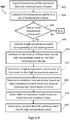
- Figure 4 is a flow diagram of a method 400 showing acts that may be performed as part of method 300.
- the method 400 involves more specific examples of the block 304 of the method 300.
- Block 402 is identical to block 302 of the method 300, in that a temperature profile of the brake with respect to time and the initial thermal oxidation state of the brake assembly 200 are input.
- the temperature profile is compared to a set of temperature criteria.
- the set of temperature criteria may include a set of temperature thresholds.
- the set of temperature criteria may include a first temperature threshold of 400°C and a second temperature threshold of 750°C. In other examples, different temperature thresholds may be used depending on the physical properties of the brake assembly 200.
- the comparison of the temperature profile may, for example, take place sequentially in time order of the temperature data contained in the temperature profile. For example, a temperature value may be compared to the set of temperature thresholds, and subsequently, the next temperature value in time may be compared to the set of temperature thresholds.
- a braking event is, for example, an application of the brake assembly 200.
- a high temperature event is an event during which the temperature of the brake assembly exceeds at least one of the temperature thresholds as a result of a braking event. For example, if during a braking event (i.e.
- the temperature of the brake assembly 200 remains below all temperature thresholds, then no high temperature events occurred during that braking event.
- the temperature of the brake assembly exceeds a temperature threshold, the part of the braking event for which that temperature threshold is exceeded may be referred to as a high temperature event. If more than one temperature threshold is exceeded, a high temperature event may be the part of the braking event for which the highest temperature threshold is exceeded.
- the temperature thresholds may be set based on temperatures above which a significant amount of thermal oxidation is expected to occur. Therefore, the method 400 ends if none of the temperature thresholds are exceeded. This is because, in this example, no braking events causing a sufficiently high temperature for thermal oxidation have occurred. In such examples, the updated thermal oxidation state after the braking event may simply be set to the initial thermal oxidation state before the braking event in question.
- a high temperature event corresponding to the braking event in question is identified.
- a high temperature event corresponds to the part of the temperature profile which is above the highest of the exceeded temperature thresholds. This is because the part of the temperature profile which is above the highest of the exceeded thresholds corresponds to the part of the braking event for which the highest temperature threshold is exceeded.
- Figure 5 is a graph illustrating a part of an example temperature profile. In the graph of Figure 5 , the vertical axis represents temperature of the brake assembly 200, and the horizontal axis represents time.
- profile part 502 indicates that the temperature of the brake assembly 200 exceeds a first temperature threshold 504 and a second temperature threshold 506.
- the high temperature event is identified as the part of the profile 502 above the second temperature threshold 506 as the second temperature threshold 506 is the highest temperature threshold which is exceeded.
- the amount of thermal oxidation which occurs above the second temperature threshold 506 may be significantly greater for a given interval of time compared to the thermal oxidation above the first temperature threshold 504 but below the second temperature threshold 506. Therefore, in this example, the parts of the temperature profile below the second temperature threshold 506 are not taken into account. In other examples, for example when the method 400 is used for live oxidation state monitoring as described further below, the parts of the temperature profile between the two temperature thresholds may be taken into account. It should be appreciated that the graph of Figure 5 is merely an illustration of an example for explanatory purposes.
- the interval of time taken by the high temperature event is determined to be the high temperature interval.
- the updated thermal oxidation state may be determined based on (among other factors) the high temperature interval.
- the high temperature interval is determined to be the time interval 508.
- a high temperature event value of the brake assembly 200 is determined for the high temperature interval.
- the high temperature event value is a value of temperature ascribed to the high temperature event.
- the high temperature event value is the average temperature during the high temperature interval. Alternatives to the high temperature event value being the average temperature are described below in the context of live oxidation monitoring.
- an oxidation rate parameter is calculated based on the high temperature event value and physical characteristic information of the brake.
- Equation 1 k ( T ) is the thermal oxidation rate, A is a pre-exponential constant, E A is the activation energy of the carbon atoms of the CC composite components of brake assembly 200, R is the universal gas constant and T is the temperature.
- the temperature T in Equation 1 is set to the high temperature event value for the purpose of block 414.
- the thermal oxidation rate k ( T ) is the oxidation parameter determined at block 414.
- the values of activation energy E A , and the pre-exponential constant A may depend on the physical properties of the CC composite components of brake assembly 200 (in this example, the brake discs 202).
- the values of these parameters may depend on the density, porosity, manufacturing process, contaminants present in the CC composite structures, the surface finish of the components and surface coatings of the brake assembly 200.
- the values of the activation energy E A , and the pre-exponential constant A may also vary depending on the high temperature event value and the initial thermal oxidation state. Therefore, in order to determine the oxidation parameter, appropriate values of activation energy E A , and the pre-exponential constant A may be selected based on the physical properties of the brake assembly 200, the high temperature event value and the initial thermal oxidation state before the braking event in question.
- the activation energy E A may be related inversely to temperature.
- the activation energy E A may become lower at a temperature at which oxygen molecules are able to penetrate past the surface of the brake discs 202 and oxidation of carbon deeper in the brake discs 202 can take place.
- the appropriate values of activation energy E A , and the pre-exponential constant A may, for example, be determined experimentally for different initial thermal oxidation amounts, temperatures and physical properties of the brake being considered before the method 400 is implemented.
- Figure 6 is a graph of an example of the evolution with time of thermal oxidation of the brake discs of a brake assembly 200 for a specific temperature.
- the vertical axis of the graph in Figure 6 represents a measure of the thermal oxidation indicated by the thermal oxidation state Ox.
- the thermal oxidation state Ox may be the proportion of mass of the brake assembly 200 lost due to thermal oxidation of the brake discs 202.
- the evolution curve 602 shows how the proportion of mass lost due to thermal oxidation advances with time at the specific temperature. It should be noted that a different evolution curve would indicate the variation of the thermal oxidation state Ox over time for a different temperature value.
- the thermal oxidation state Ox advances with time differently below a thermal oxidation state level 604, than it does above the thermal oxidation state level 604.
- the thermal oxidation state Ox i.e. mass lost due to thermal oxidation
- the thermal oxidation state Ox is shown to increase non-linearly with time below oxidation state level 604 and substantially linearly with time above oxidation state level 604, in this example.
- the thermal oxidation state increases at an accelerated rate with time until thermal oxidation state level 604 is reached. After thermal oxidation state level 604 is reached, the rate of change of thermal oxidation state Ox with time remains generally constant.
- thermal oxidation state level 604 may be considered as a first thermal oxidation zone, namely Zone 1, and the part of the graph of Figure 6 above thermal oxidation state level 604 may be considered as a second thermal oxidation zone, namely Zone 2, for example.
- different values of the activation energy E A , and the pre-exponential constant A may be used depending on which thermal oxidation zone the brake assembly 200 is in as indicated by the initial thermal oxidation state.
- a thermal oxidation model is selected based on the initial thermal oxidation state before the braking event.
- the thermal oxidation model describes the evolution of the thermal oxidation state Ox of the brake assembly 200 for different values of temperature.
- a thermal oxidation model which describes the evolution of the thermal oxidation state Ox in Zone 1 may be selected when the initial thermal oxidation state is in Zone 1.
- a thermal oxidation model which describes the evolution of the thermal oxidation state Ox in Zone 2 may be selected when the initial thermal oxidation state is in Zone 2.
- a first thermal oxidation model, Model 1 may be selected for Zone 1
- a second thermal oxidation model, Model 2 may be selected for Zone 2.
- Model 1 for Zone 1 describing the non-linear change of thermal oxidation state Ox with time
- Model 2 for Zone 2 describing the linear change of thermal oxidation state Ox with time
- Ox 1 ⁇ 1 ⁇ k T ⁇ t eq 1 ⁇ n / 1 ⁇ n 1
- Ox k T ⁇ t eq
- Equation 2 and Equation 3 above k ( T ) is the thermal oxidation rate as defined by Equation 1.
- the parameter t eq is the equivalent time, which is the time it would take, at temperature T, to reach the thermal oxidation state Ox.
- the parameter n is referred to as the equation order and depends on the properties of the CC composite used in the brake assembly 200. The parameter n may, for example be experimentally determined for a brake using a particular CC composite.
- thermal oxidation models to those described by Equations 2 and 3 may be used.
- a single thermal oxidation model may be used which describes the evolution of the thermal oxidation state Ox for all thermal oxidation states Ox that are relevant to the brake assembly 200.
- more than two thermal oxidation models may be used for respective ranges of thermal oxidation states Ox.
- the method 400 may be modified appropriately in order to use such alternative thermal oxidation models. For example, a different set of inputs may be applied to the thermal oxidation model, as appropriate, than are described in this specific example of the method 400.
- block 416 may be performed at any stage of the method 400 once block 402 has been performed, because block 416 requires the initial thermal oxidation state.
- the updated thermal oxidation state for the high temperature event is determined using the selected thermal oxidation model based on the high temperature interval, the initial thermal oxidation state and the determined thermal oxidation rate parameter. For example, the time it would take to reach the initial thermal oxidation state from zero at the high temperature value is determined and the high temperature interval is added to this time in order to determine the value of t eq to be used in the selected thermal oxidation model. Inputting the thus determined value of t eq , as well as the thermal oxidation parameter into the equation selected from Equations 2 and 3 above results in, as an output, the updated thermal oxidation state of the brake assembly 200 after the high temperature event.
- the updated thermal oxidation state may be set to the new initial thermal oxidation state for a subsequent use of the method 400 for a subsequent high temperature event in the temperature profile.
- any part of the temperature profile above at least one temperature threshold may be identified as a high temperature event. It will be understood that such modifications may allow the thermal oxidation state of the brake assembly 200 to be updated as high temperature events corresponding to braking events are taking place.
- high temperature events may be identified based on the time between subsequent temperature measurements taken by the temperature sensor 212.
- the interval 510 may be the interval of time between subsequent temperature measurements taken by the temperature sensor 212.
- the predicted temperature profiles may, for example, take into account the future flight schedule of the aircraft 100.
- the aircraft 100 may be expected to land at an airport with a short runway requiring high energy (i.e. high temperature) braking upon landing for some of its predicted future use cycles.
- the predicted temperature profiles may indicate high energy braking upon landing. It will be appreciated that various other factors may be taken into account when predicting temperature profiles such as taxiing time at various phases of a predicted future use cycle, waiting time between a taxiing phase and the preceding landing phase, and the like.
- the first plurality of predicted future use cycles may be a number of predicted future cycles after which the predicted future thermal oxidation state reaches a thermal oxidation threshold.
- the prediction of the future thermal oxidation state may stop after a cycle in which the thermal oxidation threshold is reached.
- the prediction of the future thermal oxidation state may stop as soon as the thermal oxidation threshold is reached.
- the thermal oxidation threshold may be an oxidation state at which servicing or replacement of the brake assembly 200 or a component of the brake assembly 200 is required.
- the brake assembly 200 may require a service if its mass is reduced by between 4% and 6.5%, for instance 5.7%, where the selected percentage threshold may vary depending, for instance, on the original, manufactured disc density.
- the first plurality of predicted future use cycles is the number of cycles it takes for the proportion of mass lost due to thermal oxidation to reach or exceed, for instance, 5.7% (i.e. being within the range 4% to 6.5%).
- an indication may be given as to how many use cycles can take place before the brake assembly 200 or a component of the brake assembly 200 requires servicing or replacement due to thermal oxidation.
- the thermal oxidation threshold is strictly reached or exceeded during the last of the first plurality of future cycles
- the number of cycles before a service or replacement is required due to thermal oxidation may be predicted as one fewer than the number of cycles in the first plurality.
- the prediction of the future thermal oxidation state stops when the thermal oxidation threshold is expected to be reached in the next cycle after the first plurality
- the first plurality is taken as the number of cycles before a service or replacement due to thermal oxidation is required.
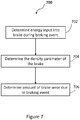
- the energy input into the brake assembly 200 during the braking event is determined.
- the energy input into the brake assembly 200 may, for example, be determined based on the characteristics of the aircraft 100 during the braking event, such as a mass of the aircraft 100, the velocity of the aircraft 100 during the braking event, etc.
- the energy absorbed by the brake assembly 200 can be calculated based on such characteristics of the aircraft 100 by determining the kinetic energy of the aircraft 100. For example, a given proportion of the kinetic energy of the aircraft 100 may be absorbed by the brake assembly 200 to reduce the kinetic energy of the aircraft 100.
- the energy input into the brake assembly 200 may be determined based on measurements acquired by the instruments 106 of the aircraft 100.
- an amount of brake wear caused by the braking event is determined, using a brake wear model based on the energy absorbed by the brake assembly 200 and the density parameter from block 704. For example, the mass of the brake assembly 200 lost due to wear during the wear event is determined using the brake wear model of Equation 4 below.
- m wear W + X + E brake + Y + E brake 2 + Z ⁇ E brake 3 1 ⁇ Ox
- Equation 4 above m wear is the mass lost due to wear during the braking event
- E brake is the energy absorbed by the brake assembly 200
- W , X , Y and Z are constants.
- the constants W , X , Y and Z may, for example, be determined by experiment beforehand, and may vary depending on the properties of the brake assembly 200.
- the brake wear amount for a braking event may be determined as a reduction in length L of the brake assembly 200 based on the reduction of mass due to brake wear during that braking event.
- the initial thermal oxidation rate is used to determine the density parameter in some examples.
- the initial thermal oxidation state may be used for the determination of block 706. This is because brake wear occurs on a much shorter timescale than thermal oxidation.
- the amount of brake wear determined for a braking event may be added to the amount of brake wear from all previous braking events of the brake assembly 200 in order to determine the total brake wear amount.
- the method 700 may, for example, be performed live during a time when braking events are taking place, or for a use cycle which has already occurred using the relevant data from that use cycle.
- the method 700 may also be used in order to predict a future brake wear amount for the brake assembly 200 after a second plurality of predicted future use cycles of the aircraft 100.
- the second plurality of predicted future use cycles may be a number of cycles after which a brake wear threshold is reached.
- Each predicted future use cycle may include a respective plurality of braking events.
- the method 700 may be performed for each braking event in the second plurality of predicted future use cycles. The wear amount from each of those braking events may be added up to predict the future brake wear amount for the second plurality of predicted future use cycles.
- the predictions may be based on predicted amounts of energy absorbed by the brake during respective braking events, and respective predicted density parameters of the brake for respective braking events.
- braking events may be identified and energy absorbed by brake assembly 200 for those braking events determined based on the predicted temperature profiles.
- predicted amounts of absorbed energy may be based on data from previous cycles. If the brake assembly 200 is new, or enough previous data is not available, the predicted amounts of energy may be predetermined.
- the method 700 may be used in combination with the method 300 or 400.
- the up to date initial thermal oxidation state just before each predicted braking event e.g. a predicted future braking event
- the mass of the brake assembly 200, and therefore the density parameter may be determined using the initial thermal oxidation before the future braking event in question.
- the second plurality of predicted future use cycles may be a number of predicted future cycles after which the predicted future brake wear amount reaches a brake wear threshold.
- the prediction of the future brake wear amount may stop after a cycle in which the brake wear threshold is reached.
- the prediction of the future brake wear amount may stop as soon as the total brake wear amount reaches the brake wear threshold.
- the brake wear threshold may be a total amount of brake wear at which servicing or replacement of the brake assembly 200 or a component of the brake assembly 200 is required.
- a brake assembly such as the brake assembly 200 of Figure 2 may require a service if its length L has been reduced by, say, 22% to 24%, depending, for example, on the kind of discs and original, manufactured density thereof.
- a reduction in length of around 50mm may trigger servicing or replacement.
- the second plurality of predicted future use cycles is the number of cycles it takes for the total brake wear amount to reach or exceed, for instance 50mm (again, for an original disc having a length L of around 221mm).
- the prediction of the future brake wear amount may stop at the end of a predicted future use cycle during which the total brake wear amount approaches close to the brake wear threshold such that the total brake wear amount can be expected to reach the brake wear threshold during the next predicted future use cycle.
- the brake wear threshold may be considered reached within the second plurality of predicted future use cycles. This is because, in reality, an aircraft 100 with the brake assembly 200 expected to reach the brake wear threshold in a strict sense in the very next cycle would not be permitted to fly and a service or replacement relating to the brake assembly 200 may take place at that point.
- an indication may be given as to how many use cycles can take place before the brake assembly 200 or a component of the brake assembly 200 requires servicing or replacement due to brake wear.
- the brake wear threshold is strictly reached or exceeded during the last of the second plurality of future cycles
- the number of cycles before a service or replacement is required due to brake wear may be predicted as one less than the number of cycles in the second plurality.
- the prediction of the future brake wear amount stops when the brake wear threshold is expected to be reached in the next cycle after the second plurality
- the second plurality is taken as the number of cycles before a service or replacement due to brake wear is required.
- Figure 8 is a flow diagram of a method 800 for determining a number of good future use cycles until one of the thermal oxidation threshold and the brake wear threshold is reached.
- the number of good future use cycles is the remaining number of future use cycles before one of the thermal oxidation threshold or the brake wear threshold is reached.
- the method 800 may be performed for a number of predicted future use cycles until the first of the thresholds is reached.
- the method 800 involves predicting a future thermal oxidation state and a future brake wear amount after a predicted future use cycle and, if one of the thermal oxidation threshold and the brake wear threshold is reached, determining a number of good future use cycles before either of the thresholds is reached. If one of the thresholds is not reached, the predictions are performed for the next predicted future use cycle.
- each predicted future use cycle includes a plurality of braking event.
- the predictions are based on a respective predicted temperature profile of the brake, a current thermal oxidation state, predicted amounts of energy absorbed by the brake during respective braking events, and respective predicted density parameters of the brake for respective braking events.
- the number of good future use cycles is a number of cycles after which servicing or replacement of the brake assembly 200 or a component of the brake assembly 200 is required. It will be appreciated that service or replacement in relation to the brake assembly 200 may be carried out when one of the thermal oxidation threshold or the brake wear threshold is first reached. Which threshold is reached first may, for example, depend on the way the aircraft 100 is handled during use and its flight schedule. For example, if the aircraft 100's schedule involves flying to mostly airports with long runways, short taxiing routes, etc., the brake wear threshold may be reached first. This is because, in such examples, the temperature of the brake assembly 200 may not often exceed any of the temperature thresholds relating to thermal oxidation. On the other hand, the aircraft 100 may often experience high energy braking (e.g. due to short runways) causing temperatures above the thresholds related to thermal oxidation. In such examples the thermal oxidation threshold may be reached first.
- high energy braking e.g. due to short runways
- a future thermal oxidation state after a predicted future use cycle is predicted.
- the prediction of the future thermal oxidation state is performed as described above, for example, using an appropriate thermal oxidation model based on a predicted temperature profile of the predicted future use cycle in question.
- a future brake wear amount after the same predicted future use cycle is predicted. The prediction is performed as described above in the context of method 700.
- the method 800 it is determined whether the thermal oxidation threshold and/or the brake wear threshold is reached. For example, if the thermal oxidation threshold is reached, the method 800 proceeds to block 808 at which a number of good future use cycles, before either of the thermal oxidation threshold or the brake wear threshold is reached, is determined, and the method 800 ends. For example, if the thermal oxidation threshold is strictly reached or exceeded after a given number of predicted future use cycles, the number of good future use cycles is one less than that given number. For example, if the thermal oxidation threshold is expected to be reached in the very next predicted future use cycle, the number of good future use cycles is determined as the number of predicted future use cycles for which the method 800 has been performed thus far.
- the method proceeds to block 808 where a number of good future use cycles is determined, and the method 800 ends. For example, if the brake wear threshold is strictly reached or exceeded after a given number of predicted future use cycles, the number of good future use cycles is one less than that given number. For example, if the brake wear threshold is expected to be reached in the very next predicted future use cycle, the number of good future use cycles is determined as the number of predicted future use cycles for which method 800 has been performed thus far.
- predictions relating to the future thermal oxidation state and/or the future brake wear state may be performed by a processor of the computing system 104.
- the methods may be performed, for example, using data from the instruments 106.
- temperature data as measured by the temperature sensor 212 may be used.
- the future temperature profiles and/or other predicted data may be predicted by a processor of the computing system 104.
- the data for prediction may be determined on a computing system not on board the aircraft 100, and may be stored in a computer readable storage medium of the computing system 104.
- An indicating device 108 of the aircraft 100 may be used to provide the pilots and/or ground crew indications relating to the thermal oxidation state, brake wear amount, a number of cycles before the thermal oxidation threshold is reached, a number of cycles before the brake wear threshold is reached and/or a number of good future use cycles.
- indications may allow the ground crew to assess aspects of the brake assembly 200 more quickly than visual or other physical inspection alone.
- Such indications may also allow appropriate scheduling of services and replacements in relation to the brake assembly 200. This may prevent delays due to grounding of the aircraft 100 at a time when a service or replacement is not scheduled because ground crew determine an issue with the brake assembly 200 which could not have been known without predictions relating to thermal oxidation and/or brake wear.
- Indications regarding thermal oxidation and/or brake wear to the pilot(s) may assist, for example, in the pilots indicating to ground crew when a service or replacement in relation to the brake assembly 200 may be required. Indications of the state of the brake assembly 200 for a previous cycle may also assist the pilot(s) of the aircraft 100 in assessing their brake application behaviour. For example, the indications may show that a particular change in braking behaviour may lead to less thermal oxidation per cycle and a greater number of good future use cycles. For example, this may occur in the case where the thermal oxidation threshold is predicted to be reached first.
- indications in relation to the thermal oxidation and/or brake wear of the brake assembly 200 may allow the pilot(s) to adjust brake application behaviour substantially in real time in order to preserve the brake assembly 200. For example, the pilot(s) may not start taxiing the aircraft 100 immediately after a landing with high energy braking, if permitted to do so, such that the temperature of the brake assembly 200 does not remain above a temperature threshold relating to thermal oxidation.
- One or more of the above described methods may be performed by a computing apparatus such as computing apparatus 900 shown in Figure 9 , for example.
- the computing apparatus 900 may be external to the aircraft 100.
- Computing apparatus 900 may comprise a processor 902 and a computer readable storage medium 904.
- the processor 902 may be configured to execute instructions stored on the storage medium 904.
- the storage medium 904 may store instructions for performing all or part of any of the above described methods.
- Data such as temperature profile information, may be provided to the computing apparatus 900 for performing the methods disclosed herein.
- live monitoring data from the aircraft may be transmitted to the computing apparatus 900.
- any of the above methods may be performed by computing apparatus 900 and the resulting indications reported to personnel responsible for the care and/or use of the aircraft 100.
- All or part of the instructions for performing the above described methods may be generated and/or the methods may be performed using any suitable software or combination of software.
- "MATLAB" may be used to generate all or part of the instructions for a processor such as processor 902 or a processor of computing system 104 to carry out any of the above methods.
- other software packages may be used.
- any suitable programming language, development environment, software package, or the like may be used.
- Other examples of programming languages include PYTHON, C++, C, JAVASCRIPT, FORTRAN etc.
Applications Claiming Priority (1)
| Application Number | Priority Date | Filing Date | Title |
|---|---|---|---|
| GB1803203.7A GB2571359A (en) | 2018-02-27 | 2018-02-27 | Brake monitoring |
Publications (2)
| Publication Number | Publication Date |
|---|---|
| EP3530531A1 true EP3530531A1 (de) | 2019-08-28 |
| EP3530531B1 EP3530531B1 (de) | 2021-06-30 |
Family
ID=61903195
Family Applications (6)
| Application Number | Title | Priority Date | Filing Date |
|---|---|---|---|
| EP19156791.6A Active EP3530531B1 (de) | 2018-02-27 | 2019-02-12 | Bremsüberwachung |
| EP23196672.2A Pending EP4324709A3 (de) | 2018-02-27 | 2019-02-27 | Flugzeugbremsung |
| EP19159656.8A Active EP3530529B1 (de) | 2018-02-27 | 2019-02-27 | Fahrzeugbremsung |
| EP19159658.4A Active EP3530533B1 (de) | 2018-02-27 | 2019-02-27 | Flugzeugbremsung |
| EP19159657.6A Active EP3530532B1 (de) | 2018-02-27 | 2019-02-27 | Bremssteuerung |
| EP21201967.3A Active EP3957528B1 (de) | 2018-02-27 | 2019-02-27 | Flugzeugbremsung |
Family Applications After (5)
| Application Number | Title | Priority Date | Filing Date |
|---|---|---|---|
| EP23196672.2A Pending EP4324709A3 (de) | 2018-02-27 | 2019-02-27 | Flugzeugbremsung |
| EP19159656.8A Active EP3530529B1 (de) | 2018-02-27 | 2019-02-27 | Fahrzeugbremsung |
| EP19159658.4A Active EP3530533B1 (de) | 2018-02-27 | 2019-02-27 | Flugzeugbremsung |
| EP19159657.6A Active EP3530532B1 (de) | 2018-02-27 | 2019-02-27 | Bremssteuerung |
| EP21201967.3A Active EP3957528B1 (de) | 2018-02-27 | 2019-02-27 | Flugzeugbremsung |
Country Status (4)
| Country | Link |
|---|---|
| US (5) | US11603086B2 (de) |
| EP (6) | EP3530531B1 (de) |
| CN (4) | CN110194279A (de) |
| GB (4) | GB2571359A (de) |
Families Citing this family (18)
| Publication number | Priority date | Publication date | Assignee | Title |
|---|---|---|---|---|
| GB2576937A (en) * | 2018-09-07 | 2020-03-11 | Airbus Operations Ltd | Controlling aircraft wheel brakes |
| GB2583706A (en) * | 2019-04-23 | 2020-11-11 | Airbus Operations Ltd | Aircraft braking system |
| GB2583486A (en) | 2019-04-29 | 2020-11-04 | Airbus Operations Ltd | Brake characteristics |
| GB2587608A (en) * | 2019-09-23 | 2021-04-07 | Airbus Operations Ltd | Predicting the life of consumable components |
| CN110905951B (zh) * | 2019-12-10 | 2021-11-26 | 深圳鼎然信息科技有限公司 | 动态实时监测汽车刹车片磨损的方法、装置、设备及介质 |
| EP3862737A1 (de) | 2020-02-05 | 2021-08-11 | Goodrich Corporation | Modellbasierte flugzeugbremstemperaturschätzung |
| EP3862238B1 (de) * | 2020-02-05 | 2023-06-07 | Goodrich Corporation | Direkte und indirekte verfahren zur abschätzung des bremsenverschleisses bei flugzeugen |
| US11400900B2 (en) | 2020-03-03 | 2022-08-02 | Hamilton Sundstrand Corporation | Selective friction brake allocation during taxi |
| GB2593709A (en) * | 2020-03-30 | 2021-10-06 | Airbus Operations Ltd | Brake mass parameter |
| FI129996B (fi) * | 2020-06-03 | 2022-12-15 | Ponsse Oyj | Työkoneen jarrulaite |
| CN111874262A (zh) * | 2020-07-08 | 2020-11-03 | 西安航空制动科技有限公司 | 一种飞机机轮刹车盘磨损检测系统 |
| US11396285B2 (en) * | 2020-07-09 | 2022-07-26 | Goodrich Corporation | Systems and methods for measuring brake wear |
| EP3936396A1 (de) | 2020-07-10 | 2022-01-12 | Goodrich Corporation | Bremskühlungsregelung |
| EP4067687A1 (de) * | 2021-03-31 | 2022-10-05 | Collins Aerospace Ireland, Limited | Bremsenverschleissstiftarchitektur |
| GB2613410A (en) * | 2021-11-30 | 2023-06-07 | Airbus Operations Ltd | Holder for component of temperature sensing system |
| US11970263B2 (en) | 2022-02-10 | 2024-04-30 | Goodrich Corporation | Hybrid brake systems and methods for load cell calibration |
| CN114838071B (zh) * | 2022-04-26 | 2024-05-03 | 浙江成峰实业有限公司 | 一种刹车片磨损在线监测及刹车片寿命估算方法 |
| WO2024054746A1 (en) * | 2022-09-07 | 2024-03-14 | Cummins Inc. | Vehicle braking management systems and methods |
Citations (3)
| Publication number | Priority date | Publication date | Assignee | Title |
|---|---|---|---|---|
| US20150025735A1 (en) * | 2013-07-16 | 2015-01-22 | Honeywell International Inc. | Aircraft brake health monitoring system and method |
| EP2988120A1 (de) * | 2014-08-22 | 2016-02-24 | Honeywell International Inc. | Leitfähigkeitssensor für flugzeugkomponenten |
| WO2017062590A1 (en) * | 2015-10-07 | 2017-04-13 | Meggitt Aircraft Braking Systems Corporation | Aircraft brake and tire condition diagnosis and prognosis |
Family Cites Families (40)
| Publication number | Priority date | Publication date | Assignee | Title |
|---|---|---|---|---|
| FR2305775A1 (fr) * | 1975-03-24 | 1976-10-22 | Aerospatiale | Procede et dispositif de commande de freins a disques |
| CA1323061C (en) * | 1988-02-16 | 1993-10-12 | Ian Leonard Stimson | Aircraft braking systems |
| US4986610A (en) * | 1989-02-21 | 1991-01-22 | Aircraft Braking Systems Corporation | Brake system with brake selection means |
| US6604708B1 (en) | 1989-12-26 | 2003-08-12 | The Boeing Company | Carbon brake wear for aircraft |
| FR2672350A1 (fr) * | 1991-02-06 | 1992-08-07 | Messier Bugatti | Dispositif de freinage controle d'un train de roues en particulier un train de roues d'avion. |
| EP0686106B1 (de) | 1993-03-06 | 1998-11-18 | Dunlop Limited | Ein sequenzieller selektiver betrieb von flugzeugbremsen |
| US5390990A (en) | 1993-11-24 | 1995-02-21 | Hydro-Aire Division Of Crane Company | Brake energy balancing system for multiple brake units |
| GB9418476D0 (en) * | 1994-09-14 | 1994-11-02 | Dunlop Ltd | Sequential selective operation of aircraft brakes |
| US6530625B2 (en) * | 1999-08-27 | 2003-03-11 | Alliedsignal Inc. | Electrically actuated brake with vibration damping |
| AU7858201A (en) * | 2000-08-04 | 2002-02-18 | Dunlop Aerospace Ltd | Brake condition monitoring |
| US6659233B2 (en) | 2001-12-04 | 2003-12-09 | Hydro-Aire, Inc. | System and method for aircraft braking system usage monitoring |
| US6882920B2 (en) * | 2003-04-29 | 2005-04-19 | Goodrich Corporation | Brake control system |
| US6851649B1 (en) | 2003-08-14 | 2005-02-08 | The Boeing Company | Methods and systems for controlling wheel brakes on aircraft and other vehicles |
| GB0322910D0 (en) | 2003-09-30 | 2003-11-05 | Meritor Heavy Vehicle Braking | Brake caliper and brake pad |
| US20060108867A1 (en) | 2004-09-17 | 2006-05-25 | Mihai Ralea | Electromechanical braking system with electrical energy back-up and regenerative energy management |
| GB0500304D0 (en) * | 2005-01-08 | 2005-02-16 | Dunlop Aerospace Ltd | Electrically actuated aircraft brakes |
| US7552627B2 (en) * | 2006-05-01 | 2009-06-30 | Goodrich Corporation | Brake wear measurement apparatus and method |
| US7717527B1 (en) | 2006-09-15 | 2010-05-18 | The Boeing Company | Alleviation of aircraft landing gear loading using a brake control scheme |
| US8634971B2 (en) * | 2009-05-05 | 2014-01-21 | Goodrich Corporation | Brake wear control system |
| US9096204B2 (en) * | 2012-12-12 | 2015-08-04 | Goodrich Corporation | System and method for determining an adaptive turnaround threshold |
| FR3000004B1 (fr) * | 2012-12-21 | 2016-12-23 | Messier Bugatti Dowty | Procede de gestion du freinage d'un aeronef. |
| US9404806B2 (en) * | 2013-03-14 | 2016-08-02 | The Boeing Company | Methods and apparatus to monitor components of an aircraft landing system |
| FR3003919B1 (fr) | 2013-03-27 | 2015-04-10 | Messier Bugatti Dowty | Procede de gestion de la duree de vie d'une pile de disques (egalement appelee puits de chaleur) d'un frein d'aeronef |
| GB201315012D0 (en) * | 2013-08-22 | 2013-10-02 | Airbus Uk Ltd | Aircraft autonomous pushback |
| US9139293B2 (en) | 2014-01-22 | 2015-09-22 | The Boeing Company | Optimized real-time antiskid control initialization for travel surfaces as a function of wheel spinup |
| US9482301B2 (en) | 2015-03-25 | 2016-11-01 | Honeywell International Inc. | Brake disc stack wear measurement |
| US9815443B2 (en) | 2015-04-30 | 2017-11-14 | The Boeing Company | Brake selection system and methods |
| EP3307619A1 (de) * | 2015-06-11 | 2018-04-18 | Engineered Arresting Systems Corporation | Flugzeugradbremsleistungskommunikationssysteme und -verfahren |
| GB2540183A (en) | 2015-07-08 | 2017-01-11 | Airbus Operations Ltd | Braking control system for an aircraft |
| DE102015226831A1 (de) | 2015-12-30 | 2017-07-06 | Siemens Aktiengesellschaft | Fahrzeug mit einer Bremseinrichtung |
| GB2549736A (en) * | 2016-04-26 | 2017-11-01 | Airbus Operations Ltd | Predicting brake cooling periods |
| US9846978B1 (en) * | 2016-06-15 | 2017-12-19 | Ford Global Technologies, Llc | Remaining useful life estimation of vehicle component |
| US10466142B2 (en) | 2016-07-13 | 2019-11-05 | Hitachi, Ltd. | Equipment control based on failure determination |
| GB2554097A (en) * | 2016-09-20 | 2018-03-28 | Airbus Operations Ltd | Brake wear reduction apparatus |
| PE20161553Z (es) * | 2016-11-09 | 2017-01-07 | Cheesman Kurt Franz Meinel | Sistema autonomo de enfriamiento de frenos para aeronaves |
| EP3339119A1 (de) * | 2016-12-22 | 2018-06-27 | Haldex Brake Products Aktiebolag | Elektrisches bremssystem für ein fahrzeug |
| GB2559329A (en) | 2017-01-26 | 2018-08-08 | Airbus Operations Ltd | Fault detection based on brake torque and temperature |
| GB2563630A (en) | 2017-06-21 | 2018-12-26 | Airbus Operations Ltd | Controlling vehicle brakes |
| US10495169B2 (en) * | 2017-07-17 | 2019-12-03 | GM Global Technology Operations LLC | Brake rotor prognosis |
| US10486674B2 (en) | 2017-09-01 | 2019-11-26 | GM Global Technology Operations LLC | Brake pad life prognosis system for regenerative braking vehicles |
-
2018
- 2018-02-27 GB GB1803203.7A patent/GB2571359A/en not_active Withdrawn
- 2018-07-06 GB GB1811179.9A patent/GB2571375A/en not_active Withdrawn
- 2018-07-06 GB GB1811178.1A patent/GB2571374A/en not_active Withdrawn
- 2018-10-29 GB GB1817600.8A patent/GB2571397A/en not_active Withdrawn
-
2019
- 2019-02-12 EP EP19156791.6A patent/EP3530531B1/de active Active
- 2019-02-25 CN CN201910137774.1A patent/CN110194279A/zh active Pending
- 2019-02-26 US US16/286,341 patent/US11603086B2/en active Active
- 2019-02-26 US US16/286,028 patent/US20190263374A1/en not_active Abandoned
- 2019-02-26 US US16/285,815 patent/US20190263373A1/en not_active Abandoned
- 2019-02-26 US US16/285,950 patent/US11814024B2/en active Active
- 2019-02-27 CN CN201910146575.7A patent/CN110194262A/zh active Pending
- 2019-02-27 EP EP23196672.2A patent/EP4324709A3/de active Pending
- 2019-02-27 EP EP19159656.8A patent/EP3530529B1/de active Active
- 2019-02-27 CN CN201910146514.0A patent/CN110194281A/zh active Pending
- 2019-02-27 EP EP19159658.4A patent/EP3530533B1/de active Active
- 2019-02-27 EP EP19159657.6A patent/EP3530532B1/de active Active
- 2019-02-27 CN CN201910146135.1A patent/CN110194280A/zh active Pending
- 2019-02-27 EP EP21201967.3A patent/EP3957528B1/de active Active
-
2021
- 2021-09-13 US US17/473,846 patent/US20210402973A1/en not_active Abandoned
Patent Citations (3)
| Publication number | Priority date | Publication date | Assignee | Title |
|---|---|---|---|---|
| US20150025735A1 (en) * | 2013-07-16 | 2015-01-22 | Honeywell International Inc. | Aircraft brake health monitoring system and method |
| EP2988120A1 (de) * | 2014-08-22 | 2016-02-24 | Honeywell International Inc. | Leitfähigkeitssensor für flugzeugkomponenten |
| WO2017062590A1 (en) * | 2015-10-07 | 2017-04-13 | Meggitt Aircraft Braking Systems Corporation | Aircraft brake and tire condition diagnosis and prognosis |
Also Published As
| Publication number | Publication date |
|---|---|
| US20190263373A1 (en) | 2019-08-29 |
| US11603086B2 (en) | 2023-03-14 |
| GB2571375A (en) | 2019-08-28 |
| CN110194280A (zh) | 2019-09-03 |
| EP4324709A3 (de) | 2024-03-06 |
| US20190263374A1 (en) | 2019-08-29 |
| US20190263375A1 (en) | 2019-08-29 |
| EP3530533B1 (de) | 2021-10-13 |
| GB201803203D0 (en) | 2018-04-11 |
| US11814024B2 (en) | 2023-11-14 |
| EP3957528B1 (de) | 2023-09-13 |
| EP3530531B1 (de) | 2021-06-30 |
| EP3957528A1 (de) | 2022-02-23 |
| EP3530532B1 (de) | 2021-03-31 |
| CN110194281A (zh) | 2019-09-03 |
| GB201811178D0 (en) | 2018-08-29 |
| GB201817600D0 (en) | 2018-12-12 |
| GB201811179D0 (en) | 2018-08-29 |
| EP4324709A2 (de) | 2024-02-21 |
| CN110194279A (zh) | 2019-09-03 |
| GB2571359A (en) | 2019-08-28 |
| GB2571397A (en) | 2019-08-28 |
| EP3530532A1 (de) | 2019-08-28 |
| US20190263510A1 (en) | 2019-08-29 |
| EP3530533A2 (de) | 2019-08-28 |
| EP3530529A1 (de) | 2019-08-28 |
| EP3530529B1 (de) | 2021-05-26 |
| GB2571374A (en) | 2019-08-28 |
| CN110194262A (zh) | 2019-09-03 |
| US20210402973A1 (en) | 2021-12-30 |
| EP3530533A3 (de) | 2019-12-18 |
Similar Documents
| Publication | Publication Date | Title |
|---|---|---|
| EP3530531B1 (de) | Bremsüberwachung | |
| US11623621B2 (en) | Brake characteristics | |
| EP3091410B1 (de) | Verfahren und system zur datenanalyse | |
| EP3543118B1 (de) | Fahrwerkstemperaturmerkmal | |
| US20150286215A1 (en) | Methods and apparatus to predict landing system operating parameters | |
| EP3892503B1 (de) | Bremsmassenparameter | |
| Wanhill et al. | Fracture mechanics in aircraft failure analysis: Uses and limitations | |
| Antolick et al. | Application of Advanced Vibration Techniques for Enhancing Bearing Diagnostics on a HUMS-Equipped Fleet | |
| Reis et al. | Methodology for fatigue life assessment of the structural integrity of fighter aircraft | |
| Gillet et al. | Fatigue Crack Growth Approach for Fleet Monitoring | |
| Li et al. | Research on the Scatter of Structural Load-Time History in a Fleet | |
| Zijp | Remaining useful life estimation framework for maintenance improvement of a helicopter main rotor shaft using fracture mechanics | |
| Tinga et al. | Usage-and Condition-Based Maintenance | |
| Ignatovich et al. | Probability distribution of the lengths of fatigue cracks in riveted joints of an aircraft | |
| Mariani et al. | Effectiveness of structural usage monitoring (SUM) and transmission usage monitoring (TUM) in military and civil applications | |
| Giglio et al. | Effect of Flight Spectrum Loads on the Damage Tolerance Evaluation of a Helicopter Frame |
Legal Events
| Date | Code | Title | Description |
|---|---|---|---|
| PUAI | Public reference made under article 153(3) epc to a published international application that has entered the european phase |
Free format text: ORIGINAL CODE: 0009012 |
|
| STAA | Information on the status of an ep patent application or granted ep patent |
Free format text: STATUS: THE APPLICATION HAS BEEN PUBLISHED |
|
| AK | Designated contracting states |
Kind code of ref document: A1 Designated state(s): AL AT BE BG CH CY CZ DE DK EE ES FI FR GB GR HR HU IE IS IT LI LT LU LV MC MK MT NL NO PL PT RO RS SE SI SK SM TR |
|
| AX | Request for extension of the european patent |
Extension state: BA ME |
|
| STAA | Information on the status of an ep patent application or granted ep patent |
Free format text: STATUS: REQUEST FOR EXAMINATION WAS MADE |
|
| 17P | Request for examination filed |
Effective date: 20200228 |
|
| RBV | Designated contracting states (corrected) |
Designated state(s): AL AT BE BG CH CY CZ DE DK EE ES FI FR GB GR HR HU IE IS IT LI LT LU LV MC MK MT NL NO PL PT RO RS SE SI SK SM TR |
|
| RIC1 | Information provided on ipc code assigned before grant |
Ipc: B60T 17/22 20060101AFI20200403BHEP |
|
| GRAP | Despatch of communication of intention to grant a patent |
Free format text: ORIGINAL CODE: EPIDOSNIGR1 |
|
| STAA | Information on the status of an ep patent application or granted ep patent |
Free format text: STATUS: GRANT OF PATENT IS INTENDED |
|
| INTG | Intention to grant announced |
Effective date: 20200624 |
|
| GRAJ | Information related to disapproval of communication of intention to grant by the applicant or resumption of examination proceedings by the epo deleted |
Free format text: ORIGINAL CODE: EPIDOSDIGR1 |
|
| STAA | Information on the status of an ep patent application or granted ep patent |
Free format text: STATUS: REQUEST FOR EXAMINATION WAS MADE |
|
| INTC | Intention to grant announced (deleted) | ||
| GRAP | Despatch of communication of intention to grant a patent |
Free format text: ORIGINAL CODE: EPIDOSNIGR1 |
|
| STAA | Information on the status of an ep patent application or granted ep patent |
Free format text: STATUS: GRANT OF PATENT IS INTENDED |
|
| INTG | Intention to grant announced |
Effective date: 20210122 |
|
| GRAS | Grant fee paid |
Free format text: ORIGINAL CODE: EPIDOSNIGR3 |
|
| GRAA | (expected) grant |
Free format text: ORIGINAL CODE: 0009210 |
|
| STAA | Information on the status of an ep patent application or granted ep patent |
Free format text: STATUS: THE PATENT HAS BEEN GRANTED |
|
| AK | Designated contracting states |
Kind code of ref document: B1 Designated state(s): AL AT BE BG CH CY CZ DE DK EE ES FI FR GB GR HR HU IE IS IT LI LT LU LV MC MK MT NL NO PL PT RO RS SE SI SK SM TR |
|
| REG | Reference to a national code |
Ref country code: CH Ref legal event code: EP |
|
| REG | Reference to a national code |
Ref country code: AT Ref legal event code: REF Ref document number: 1406103 Country of ref document: AT Kind code of ref document: T Effective date: 20210715 |
|
| REG | Reference to a national code |
Ref country code: DE Ref legal event code: R096 Ref document number: 602019005623 Country of ref document: DE |
|
| REG | Reference to a national code |
Ref country code: IE Ref legal event code: FG4D |
|
| REG | Reference to a national code |
Ref country code: LT Ref legal event code: MG9D |
|
| PG25 | Lapsed in a contracting state [announced via postgrant information from national office to epo] |
Ref country code: FI Free format text: LAPSE BECAUSE OF FAILURE TO SUBMIT A TRANSLATION OF THE DESCRIPTION OR TO PAY THE FEE WITHIN THE PRESCRIBED TIME-LIMIT Effective date: 20210630 Ref country code: HR Free format text: LAPSE BECAUSE OF FAILURE TO SUBMIT A TRANSLATION OF THE DESCRIPTION OR TO PAY THE FEE WITHIN THE PRESCRIBED TIME-LIMIT Effective date: 20210630 Ref country code: BG Free format text: LAPSE BECAUSE OF FAILURE TO SUBMIT A TRANSLATION OF THE DESCRIPTION OR TO PAY THE FEE WITHIN THE PRESCRIBED TIME-LIMIT Effective date: 20210930 |
|
| REG | Reference to a national code |
Ref country code: NL Ref legal event code: MP Effective date: 20210630 |
|
| REG | Reference to a national code |
Ref country code: AT Ref legal event code: MK05 Ref document number: 1406103 Country of ref document: AT Kind code of ref document: T Effective date: 20210630 |
|
| PG25 | Lapsed in a contracting state [announced via postgrant information from national office to epo] |
Ref country code: GR Free format text: LAPSE BECAUSE OF FAILURE TO SUBMIT A TRANSLATION OF THE DESCRIPTION OR TO PAY THE FEE WITHIN THE PRESCRIBED TIME-LIMIT Effective date: 20211001 Ref country code: NO Free format text: LAPSE BECAUSE OF FAILURE TO SUBMIT A TRANSLATION OF THE DESCRIPTION OR TO PAY THE FEE WITHIN THE PRESCRIBED TIME-LIMIT Effective date: 20210930 Ref country code: LV Free format text: LAPSE BECAUSE OF FAILURE TO SUBMIT A TRANSLATION OF THE DESCRIPTION OR TO PAY THE FEE WITHIN THE PRESCRIBED TIME-LIMIT Effective date: 20210630 Ref country code: SE Free format text: LAPSE BECAUSE OF FAILURE TO SUBMIT A TRANSLATION OF THE DESCRIPTION OR TO PAY THE FEE WITHIN THE PRESCRIBED TIME-LIMIT Effective date: 20210630 Ref country code: RS Free format text: LAPSE BECAUSE OF FAILURE TO SUBMIT A TRANSLATION OF THE DESCRIPTION OR TO PAY THE FEE WITHIN THE PRESCRIBED TIME-LIMIT Effective date: 20210630 |
|
| PG25 | Lapsed in a contracting state [announced via postgrant information from national office to epo] |
Ref country code: SK Free format text: LAPSE BECAUSE OF FAILURE TO SUBMIT A TRANSLATION OF THE DESCRIPTION OR TO PAY THE FEE WITHIN THE PRESCRIBED TIME-LIMIT Effective date: 20210630 Ref country code: ES Free format text: LAPSE BECAUSE OF FAILURE TO SUBMIT A TRANSLATION OF THE DESCRIPTION OR TO PAY THE FEE WITHIN THE PRESCRIBED TIME-LIMIT Effective date: 20210630 Ref country code: EE Free format text: LAPSE BECAUSE OF FAILURE TO SUBMIT A TRANSLATION OF THE DESCRIPTION OR TO PAY THE FEE WITHIN THE PRESCRIBED TIME-LIMIT Effective date: 20210630 Ref country code: NL Free format text: LAPSE BECAUSE OF FAILURE TO SUBMIT A TRANSLATION OF THE DESCRIPTION OR TO PAY THE FEE WITHIN THE PRESCRIBED TIME-LIMIT Effective date: 20210630 Ref country code: PT Free format text: LAPSE BECAUSE OF FAILURE TO SUBMIT A TRANSLATION OF THE DESCRIPTION OR TO PAY THE FEE WITHIN THE PRESCRIBED TIME-LIMIT Effective date: 20211102 Ref country code: RO Free format text: LAPSE BECAUSE OF FAILURE TO SUBMIT A TRANSLATION OF THE DESCRIPTION OR TO PAY THE FEE WITHIN THE PRESCRIBED TIME-LIMIT Effective date: 20210630 Ref country code: SM Free format text: LAPSE BECAUSE OF FAILURE TO SUBMIT A TRANSLATION OF THE DESCRIPTION OR TO PAY THE FEE WITHIN THE PRESCRIBED TIME-LIMIT Effective date: 20210630 Ref country code: AT Free format text: LAPSE BECAUSE OF FAILURE TO SUBMIT A TRANSLATION OF THE DESCRIPTION OR TO PAY THE FEE WITHIN THE PRESCRIBED TIME-LIMIT Effective date: 20210630 Ref country code: CZ Free format text: LAPSE BECAUSE OF FAILURE TO SUBMIT A TRANSLATION OF THE DESCRIPTION OR TO PAY THE FEE WITHIN THE PRESCRIBED TIME-LIMIT Effective date: 20210630 |
|
| PG25 | Lapsed in a contracting state [announced via postgrant information from national office to epo] |
Ref country code: PL Free format text: LAPSE BECAUSE OF FAILURE TO SUBMIT A TRANSLATION OF THE DESCRIPTION OR TO PAY THE FEE WITHIN THE PRESCRIBED TIME-LIMIT Effective date: 20210630 |
|
| REG | Reference to a national code |
Ref country code: DE Ref legal event code: R097 Ref document number: 602019005623 Country of ref document: DE |
|
| PG25 | Lapsed in a contracting state [announced via postgrant information from national office to epo] |
Ref country code: DK Free format text: LAPSE BECAUSE OF FAILURE TO SUBMIT A TRANSLATION OF THE DESCRIPTION OR TO PAY THE FEE WITHIN THE PRESCRIBED TIME-LIMIT Effective date: 20210630 |
|
| PLBE | No opposition filed within time limit |
Free format text: ORIGINAL CODE: 0009261 |
|
| STAA | Information on the status of an ep patent application or granted ep patent |
Free format text: STATUS: NO OPPOSITION FILED WITHIN TIME LIMIT |
|
| PG25 | Lapsed in a contracting state [announced via postgrant information from national office to epo] |
Ref country code: AL Free format text: LAPSE BECAUSE OF FAILURE TO SUBMIT A TRANSLATION OF THE DESCRIPTION OR TO PAY THE FEE WITHIN THE PRESCRIBED TIME-LIMIT Effective date: 20210630 |
|
| 26N | No opposition filed |
Effective date: 20220331 |
|
| PG25 | Lapsed in a contracting state [announced via postgrant information from national office to epo] |
Ref country code: IT Free format text: LAPSE BECAUSE OF FAILURE TO SUBMIT A TRANSLATION OF THE DESCRIPTION OR TO PAY THE FEE WITHIN THE PRESCRIBED TIME-LIMIT Effective date: 20210630 |
|
| PG25 | Lapsed in a contracting state [announced via postgrant information from national office to epo] |
Ref country code: MC Free format text: LAPSE BECAUSE OF FAILURE TO SUBMIT A TRANSLATION OF THE DESCRIPTION OR TO PAY THE FEE WITHIN THE PRESCRIBED TIME-LIMIT Effective date: 20210630 |
|
| REG | Reference to a national code |
Ref country code: CH Ref legal event code: PL |
|
| REG | Reference to a national code |
Ref country code: BE Ref legal event code: MM Effective date: 20220228 |
|
| PG25 | Lapsed in a contracting state [announced via postgrant information from national office to epo] |
Ref country code: LU Free format text: LAPSE BECAUSE OF NON-PAYMENT OF DUE FEES Effective date: 20220212 |
|
| PG25 | Lapsed in a contracting state [announced via postgrant information from national office to epo] |
Ref country code: LI Free format text: LAPSE BECAUSE OF NON-PAYMENT OF DUE FEES Effective date: 20220228 Ref country code: IE Free format text: LAPSE BECAUSE OF NON-PAYMENT OF DUE FEES Effective date: 20220212 Ref country code: CH Free format text: LAPSE BECAUSE OF NON-PAYMENT OF DUE FEES Effective date: 20220228 |
|
| PG25 | Lapsed in a contracting state [announced via postgrant information from national office to epo] |
Ref country code: BE Free format text: LAPSE BECAUSE OF NON-PAYMENT OF DUE FEES Effective date: 20220228 |
|
| PG25 | Lapsed in a contracting state [announced via postgrant information from national office to epo] |
Ref country code: LT Free format text: LAPSE BECAUSE OF FAILURE TO SUBMIT A TRANSLATION OF THE DESCRIPTION OR TO PAY THE FEE WITHIN THE PRESCRIBED TIME-LIMIT Effective date: 20210630 |
|
| PGFP | Annual fee paid to national office [announced via postgrant information from national office to epo] |
Ref country code: FR Payment date: 20230221 Year of fee payment: 5 |
|
| PGFP | Annual fee paid to national office [announced via postgrant information from national office to epo] |
Ref country code: GB Payment date: 20230221 Year of fee payment: 5 Ref country code: DE Payment date: 20230216 Year of fee payment: 5 |
|
| PG25 | Lapsed in a contracting state [announced via postgrant information from national office to epo] |
Ref country code: MK Free format text: LAPSE BECAUSE OF FAILURE TO SUBMIT A TRANSLATION OF THE DESCRIPTION OR TO PAY THE FEE WITHIN THE PRESCRIBED TIME-LIMIT Effective date: 20210630 Ref country code: CY Free format text: LAPSE BECAUSE OF FAILURE TO SUBMIT A TRANSLATION OF THE DESCRIPTION OR TO PAY THE FEE WITHIN THE PRESCRIBED TIME-LIMIT Effective date: 20210630 |
|
| PGFP | Annual fee paid to national office [announced via postgrant information from national office to epo] |
Ref country code: DE Payment date: 20240219 Year of fee payment: 6 Ref country code: GB Payment date: 20240219 Year of fee payment: 6 |