EP3530430A1 - Blow molding device and method for manufacturing synthetic resin container using same - Google Patents
Blow molding device and method for manufacturing synthetic resin container using same Download PDFInfo
- Publication number
- EP3530430A1 EP3530430A1 EP17862119.9A EP17862119A EP3530430A1 EP 3530430 A1 EP3530430 A1 EP 3530430A1 EP 17862119 A EP17862119 A EP 17862119A EP 3530430 A1 EP3530430 A1 EP 3530430A1
- Authority
- EP
- European Patent Office
- Prior art keywords
- blow molding
- preform
- bottom mold
- stretch rod
- mold
- Prior art date
- Legal status (The legal status is an assumption and is not a legal conclusion. Google has not performed a legal analysis and makes no representation as to the accuracy of the status listed.)
- Withdrawn
Links
- 238000000071 blow moulding Methods 0.000 title claims abstract description 78
- 229920003002 synthetic resin Polymers 0.000 title claims abstract description 19
- 239000000057 synthetic resin Substances 0.000 title claims abstract description 19
- 238000000034 method Methods 0.000 title claims description 21
- 238000004519 manufacturing process Methods 0.000 title claims description 20
- 230000003028 elevating effect Effects 0.000 claims description 4
- 238000000465 moulding Methods 0.000 claims description 4
- -1 polyethylene terephthalate Polymers 0.000 description 5
- 238000007664 blowing Methods 0.000 description 4
- 230000004048 modification Effects 0.000 description 4
- 238000012986 modification Methods 0.000 description 4
- 238000001816 cooling Methods 0.000 description 3
- 229920000139 polyethylene terephthalate Polymers 0.000 description 3
- 239000005020 polyethylene terephthalate Substances 0.000 description 3
- 229920005989 resin Polymers 0.000 description 3
- 239000011347 resin Substances 0.000 description 3
- 229920005992 thermoplastic resin Polymers 0.000 description 3
- 239000004278 EU approved seasoning Substances 0.000 description 2
- 235000013361 beverage Nutrition 0.000 description 2
- 235000011194 food seasoning agent Nutrition 0.000 description 2
- 239000000203 mixture Substances 0.000 description 2
- 229920000728 polyester Polymers 0.000 description 2
- 229920001169 thermoplastic Polymers 0.000 description 2
- 239000004416 thermosoftening plastic Substances 0.000 description 2
- LLLVZDVNHNWSDS-UHFFFAOYSA-N 4-methylidene-3,5-dioxabicyclo[5.2.2]undeca-1(9),7,10-triene-2,6-dione Chemical compound C1(C2=CC=C(C(=O)OC(=C)O1)C=C2)=O LLLVZDVNHNWSDS-UHFFFAOYSA-N 0.000 description 1
- 238000000748 compression moulding Methods 0.000 description 1
- 229920001577 copolymer Polymers 0.000 description 1
- 230000000694 effects Effects 0.000 description 1
- 238000001746 injection moulding Methods 0.000 description 1
- 229920003207 poly(ethylene-2,6-naphthalate) Polymers 0.000 description 1
- 229920000747 poly(lactic acid) Polymers 0.000 description 1
- 229920001707 polybutylene terephthalate Polymers 0.000 description 1
- 239000011112 polyethylene naphthalate Substances 0.000 description 1
- 239000004626 polylactic acid Substances 0.000 description 1
- 239000000243 solution Substances 0.000 description 1
- 239000000126 substance Substances 0.000 description 1
Images


Classifications
-
- B—PERFORMING OPERATIONS; TRANSPORTING
- B29—WORKING OF PLASTICS; WORKING OF SUBSTANCES IN A PLASTIC STATE IN GENERAL
- B29C—SHAPING OR JOINING OF PLASTICS; SHAPING OF MATERIAL IN A PLASTIC STATE, NOT OTHERWISE PROVIDED FOR; AFTER-TREATMENT OF THE SHAPED PRODUCTS, e.g. REPAIRING
- B29C49/00—Blow-moulding, i.e. blowing a preform or parison to a desired shape within a mould; Apparatus therefor
- B29C49/08—Biaxial stretching during blow-moulding
- B29C49/10—Biaxial stretching during blow-moulding using mechanical means for prestretching
- B29C49/12—Stretching rods
-
- B—PERFORMING OPERATIONS; TRANSPORTING
- B29—WORKING OF PLASTICS; WORKING OF SUBSTANCES IN A PLASTIC STATE IN GENERAL
- B29C—SHAPING OR JOINING OF PLASTICS; SHAPING OF MATERIAL IN A PLASTIC STATE, NOT OTHERWISE PROVIDED FOR; AFTER-TREATMENT OF THE SHAPED PRODUCTS, e.g. REPAIRING
- B29C49/00—Blow-moulding, i.e. blowing a preform or parison to a desired shape within a mould; Apparatus therefor
- B29C49/08—Biaxial stretching during blow-moulding
- B29C49/10—Biaxial stretching during blow-moulding using mechanical means for prestretching
- B29C49/14—Clamps
-
- B—PERFORMING OPERATIONS; TRANSPORTING
- B29—WORKING OF PLASTICS; WORKING OF SUBSTANCES IN A PLASTIC STATE IN GENERAL
- B29C—SHAPING OR JOINING OF PLASTICS; SHAPING OF MATERIAL IN A PLASTIC STATE, NOT OTHERWISE PROVIDED FOR; AFTER-TREATMENT OF THE SHAPED PRODUCTS, e.g. REPAIRING
- B29C49/00—Blow-moulding, i.e. blowing a preform or parison to a desired shape within a mould; Apparatus therefor
- B29C49/42—Component parts, details or accessories; Auxiliary operations
- B29C49/78—Measuring, controlling or regulating
-
- B—PERFORMING OPERATIONS; TRANSPORTING
- B29—WORKING OF PLASTICS; WORKING OF SUBSTANCES IN A PLASTIC STATE IN GENERAL
- B29C—SHAPING OR JOINING OF PLASTICS; SHAPING OF MATERIAL IN A PLASTIC STATE, NOT OTHERWISE PROVIDED FOR; AFTER-TREATMENT OF THE SHAPED PRODUCTS, e.g. REPAIRING
- B29C49/00—Blow-moulding, i.e. blowing a preform or parison to a desired shape within a mould; Apparatus therefor
- B29C49/42—Component parts, details or accessories; Auxiliary operations
- B29C49/48—Moulds
- B29C49/4802—Moulds with means for locally compressing part(s) of the parison in the main blowing cavity
- B29C2049/4807—Moulds with means for locally compressing part(s) of the parison in the main blowing cavity by movable mould parts in the mould halves
- B29C2049/481—Moulds with means for locally compressing part(s) of the parison in the main blowing cavity by movable mould parts in the mould halves the movable mould parts moving outwardly, e.g. the mould size being increased due to the movement of the movable mould parts
-
- B—PERFORMING OPERATIONS; TRANSPORTING
- B29—WORKING OF PLASTICS; WORKING OF SUBSTANCES IN A PLASTIC STATE IN GENERAL
- B29C—SHAPING OR JOINING OF PLASTICS; SHAPING OF MATERIAL IN A PLASTIC STATE, NOT OTHERWISE PROVIDED FOR; AFTER-TREATMENT OF THE SHAPED PRODUCTS, e.g. REPAIRING
- B29C49/00—Blow-moulding, i.e. blowing a preform or parison to a desired shape within a mould; Apparatus therefor
- B29C49/42—Component parts, details or accessories; Auxiliary operations
- B29C49/48—Moulds
- B29C2049/4879—Moulds characterised by mould configurations
- B29C2049/4892—Mould halves consisting of an independent main and bottom part
-
- B—PERFORMING OPERATIONS; TRANSPORTING
- B29—WORKING OF PLASTICS; WORKING OF SUBSTANCES IN A PLASTIC STATE IN GENERAL
- B29C—SHAPING OR JOINING OF PLASTICS; SHAPING OF MATERIAL IN A PLASTIC STATE, NOT OTHERWISE PROVIDED FOR; AFTER-TREATMENT OF THE SHAPED PRODUCTS, e.g. REPAIRING
- B29C49/00—Blow-moulding, i.e. blowing a preform or parison to a desired shape within a mould; Apparatus therefor
- B29C49/42—Component parts, details or accessories; Auxiliary operations
- B29C49/78—Measuring, controlling or regulating
- B29C49/783—Measuring, controlling or regulating blowing pressure
- B29C2049/7834—Pressure increase speed, e.g. dependent on stretch or position
-
- B—PERFORMING OPERATIONS; TRANSPORTING
- B29—WORKING OF PLASTICS; WORKING OF SUBSTANCES IN A PLASTIC STATE IN GENERAL
- B29C—SHAPING OR JOINING OF PLASTICS; SHAPING OF MATERIAL IN A PLASTIC STATE, NOT OTHERWISE PROVIDED FOR; AFTER-TREATMENT OF THE SHAPED PRODUCTS, e.g. REPAIRING
- B29C49/00—Blow-moulding, i.e. blowing a preform or parison to a desired shape within a mould; Apparatus therefor
- B29C49/42—Component parts, details or accessories; Auxiliary operations
- B29C49/78—Measuring, controlling or regulating
- B29C2049/7879—Stretching, e.g. stretch rod
-
- B—PERFORMING OPERATIONS; TRANSPORTING
- B29—WORKING OF PLASTICS; WORKING OF SUBSTANCES IN A PLASTIC STATE IN GENERAL
- B29C—SHAPING OR JOINING OF PLASTICS; SHAPING OF MATERIAL IN A PLASTIC STATE, NOT OTHERWISE PROVIDED FOR; AFTER-TREATMENT OF THE SHAPED PRODUCTS, e.g. REPAIRING
- B29C2949/00—Indexing scheme relating to blow-moulding
- B29C2949/07—Preforms or parisons characterised by their configuration
- B29C2949/0715—Preforms or parisons characterised by their configuration the preform having one end closed
-
- B—PERFORMING OPERATIONS; TRANSPORTING
- B29—WORKING OF PLASTICS; WORKING OF SUBSTANCES IN A PLASTIC STATE IN GENERAL
- B29C—SHAPING OR JOINING OF PLASTICS; SHAPING OF MATERIAL IN A PLASTIC STATE, NOT OTHERWISE PROVIDED FOR; AFTER-TREATMENT OF THE SHAPED PRODUCTS, e.g. REPAIRING
- B29C49/00—Blow-moulding, i.e. blowing a preform or parison to a desired shape within a mould; Apparatus therefor
- B29C49/02—Combined blow-moulding and manufacture of the preform or the parison
- B29C49/04—Extrusion blow-moulding
- B29C49/04118—Means for supporting the extruded parison
-
- B—PERFORMING OPERATIONS; TRANSPORTING
- B29—WORKING OF PLASTICS; WORKING OF SUBSTANCES IN A PLASTIC STATE IN GENERAL
- B29C—SHAPING OR JOINING OF PLASTICS; SHAPING OF MATERIAL IN A PLASTIC STATE, NOT OTHERWISE PROVIDED FOR; AFTER-TREATMENT OF THE SHAPED PRODUCTS, e.g. REPAIRING
- B29C49/00—Blow-moulding, i.e. blowing a preform or parison to a desired shape within a mould; Apparatus therefor
- B29C49/02—Combined blow-moulding and manufacture of the preform or the parison
- B29C49/06—Injection blow-moulding
-
- B—PERFORMING OPERATIONS; TRANSPORTING
- B29—WORKING OF PLASTICS; WORKING OF SUBSTANCES IN A PLASTIC STATE IN GENERAL
- B29C—SHAPING OR JOINING OF PLASTICS; SHAPING OF MATERIAL IN A PLASTIC STATE, NOT OTHERWISE PROVIDED FOR; AFTER-TREATMENT OF THE SHAPED PRODUCTS, e.g. REPAIRING
- B29C49/00—Blow-moulding, i.e. blowing a preform or parison to a desired shape within a mould; Apparatus therefor
- B29C49/08—Biaxial stretching during blow-moulding
- B29C49/087—Means for providing controlled or limited stretch ratio
-
- B—PERFORMING OPERATIONS; TRANSPORTING
- B29—WORKING OF PLASTICS; WORKING OF SUBSTANCES IN A PLASTIC STATE IN GENERAL
- B29C—SHAPING OR JOINING OF PLASTICS; SHAPING OF MATERIAL IN A PLASTIC STATE, NOT OTHERWISE PROVIDED FOR; AFTER-TREATMENT OF THE SHAPED PRODUCTS, e.g. REPAIRING
- B29C49/00—Blow-moulding, i.e. blowing a preform or parison to a desired shape within a mould; Apparatus therefor
- B29C49/42—Component parts, details or accessories; Auxiliary operations
- B29C49/4273—Auxiliary operations after the blow-moulding operation not otherwise provided for
- B29C49/4283—Deforming the finished article
-
- B—PERFORMING OPERATIONS; TRANSPORTING
- B29—WORKING OF PLASTICS; WORKING OF SUBSTANCES IN A PLASTIC STATE IN GENERAL
- B29C—SHAPING OR JOINING OF PLASTICS; SHAPING OF MATERIAL IN A PLASTIC STATE, NOT OTHERWISE PROVIDED FOR; AFTER-TREATMENT OF THE SHAPED PRODUCTS, e.g. REPAIRING
- B29C49/00—Blow-moulding, i.e. blowing a preform or parison to a desired shape within a mould; Apparatus therefor
- B29C49/42—Component parts, details or accessories; Auxiliary operations
- B29C49/48—Moulds
- B29C49/54—Moulds for undercut articles
- B29C49/541—Moulds for undercut articles having a recessed undersurface
Definitions
- the invention relates to a blow molding device including an elevatable bottom mold, and a method for manufacturing a synthetic resin container using the blow molding device.
- a synthetic resin container formed by producing a bottomed tubular preform from a thermoplastic resin such as polyethylene terephthalate and then molding the preform into a bottle shape by biaxial stretch-blow molding, for example, has been used as a container for various beverages, various seasonings, and the like in a wide range of fields.
- Patent Literature 1 proposes a method for manufacturing a synthetic-resin-made bottle using a blow molding device including an elevatable bottom mold, in which a preform is stretched while a bottom mold is lowered, and then a bottom-push up step of pushing up the bottom side of the stretched preform by elevating the bottom mold is performed to form the final shape.
- the container can be formed thinner, and the bottom of the container can absorb pressure reduction.
- Patent Literature 1 Japanese Patent Laid-Open No. 2008-254244
- the invention has been made in view of the foregoing circumstances, and aims to provide a blow molding device and a method for manufacturing a synthetic resin container using the blow molding device, the blow molding device capable of suppressing deviation of the stretching direction of a preform from the axial direction while avoiding interference between a bottom mold and a stretch rod when a synthetic resin container is blow molded by use of the blow molding device including an elevatable bottom mold.
- the blow molding device of the invention is a blow molding device that molds a bottomed tubular preform into a predetermined container shape by blow molding, the blow molding device including: a body mold formed of an openable split mold; a bottom mold incorporated on the bottom side of the body mold to be elevatable between a first blow molding position and a second blow molding position; a stretch rod configured to stretch the preform in the axial direction; and a push rod installed in a center part of the bottom mold on the same axis as the stretch rod and vertically movable in the axial direction, in which: the movement of the stretch rod is controlled such that when the downwardly moving stretch rod reaches a bottommost point while stretching the preform, the stretch rod stops at a position avoiding interference with the bottom mold in the second blow molding position; and the movement of the push rod is controlled such that the push rod protruding from the bottom mold moves downward and retracts into the bottom mold while supporting the stretching preform separated from the stopped stretch rod.
- a method for manufacturing a synthetic resin container of the invention is a method for manufacturing a synthetic resin container using the above blow molding device, the method including the steps of: when blow molding is performed on the preform set in the blow molding device in which the body mold is closed with the bottom mold lowered to the first blow molding position, further stretching, while supporting with the push rod, the stretching preform separated from the stretch rod stopped at a bottommost point; and when the bottom side of the stretched preform reaches the bottom mold in the first blow molding position, elevating the bottom mold to the second blow molding position to push back and invert the bottom side of the stretched preform, thereby forming the stretched preform according to an inner shape of the body mold and the bottom mold and molding the preform into a predetermined container shape.
- the stretch rod by stopping the stretch rod in a position avoiding interference with the bottom mold, interference between the bottom mold and the stretch rod can be avoided. Moreover, by supporting the stretching preform separated from the stopped stretch rod by the push rod, deviation of the stretching direction of the preform from the axial direction can be suppressed.
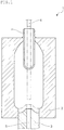
- Figure 1 shows an outline of a blow molding device of the invention as one embodiment.
- a blow molding device 1 shown in Figure 1 is intended to mold a bottomed tubular preform P into a predetermined container shape by blow molding.
- the blow molding device 1 includes a body mold 2 formed of an openable split mold, a bottom mold 3 incorporated on the bottom side of the body mold 2 to be elevatable between a first blow molding position and a second blow molding position, a stretch rod 4 that stretches the preform P in the axial direction, and a push rod 5 installed in a center part of the bottom mold 3 on the same axis as the stretch rod 4 and vertically movable in the axial direction.
- the stretch rod 4 included in the blow molding device 1 is configured to be vertically movable in the axial direction by an unillustrated drive unit.
- the movement of the stretch rod 4 is controlled such that when the downwardly moving stretch rod 4 reaches a bottommost point while stretching the preform P, the stretch rod 4 stops at a position avoiding interference with the bottom mold 3 in the second blow molding position as indicated by the chain double-dashed line in Figure 1 .
- the movement of the stretch rod 4 is controlled such that the stretch rod 4 is positioned above the bottom mold 3 and does not interfere with the bottom mold 3 when the bottom mold 3 is elevated to the second blow molding position.
- the push rod 5 included in the blow molding device 1 is configured to be vertically movable on the same axis as the stretch rod 4 by an unillustrated drive unit. The movement of the push rod 5 is controlled such that the push rod 5 protruding from the bottom mold 3 moves downward and retracts into the bottom mold 3 while supporting the stretching preform P separated from the stopped stretch rod 4.
- the upper and lower, right and left, and horizontal and vertical directions of the blow molding device 1 defined herein are directions defined in the state shown in Figure 1 where the bottom mold 3 side is the lower side.
- a method for manufacturing a synthetic resin container of the invention can be carried out appropriately by using the blow molding device 1 described above.
- the method an example of producing a synthetic resin container by using the blow molding device 1 will be described while giving further detail on the blow molding device 1.
- the preform P is made of thermoplastic resin, and is molded into the bottomed tubular shape in Figure 2 (a) by injection molding or compression molding, for example.
- the vicinity of an opening of the preform P is formed so as to serve as a mouth part of the container as it is.
- the thermoplastic resin include thermoplastic polyester such as polyethylene terephthalate, polybutylene terephthalate, polyethylene naphthalate, polylactic acid, and a copolymer of these substances, and a mixture of these resins or a mixture with other resins. While ethylene terephthalate-based thermoplastic polyester such as polyethylene terephthalate is particularly preferable, the embodiment is not limited thereto.
- the push rod 5 is moved upward and protruded from the bottom mold 3 (see Figure 2 (b) ). At this time, the protrusion length of the push rod 5 may be set appropriately depending on the stop position of the stretch rod 4.
- the movement of the stretch rod 4 is controlled such that the stretch rod 4 stops at a bottommost point which is a position where interference with the bottom mold 3 in the second blow molding position is avoided.
- the push rod 5 is controlled to wait while protruding by a predetermined protrusion length from the bottom mold 3, so that the tip end of the push rod 5 comes close to the tip end of the stretch rod 4 when the stretch rod 4 stops at the bottommost point.
- the stretch rod 4 is moved downward and blow molding is started by blowing air into the preform P from an unillustrated blow air supply unit.
- the preform P is stretched not only in the axial direction (vertical direction) by the stretch rod 4, but also in the circumferential direction (lateral direction) by blow air (see Figure 2 (c) and (d) ).
- the preform P can be stretched uniformly by appropriately adjusting the lowering speed of the stretch rod 4 and the blow air pressure.
- the preform P stretching while being supported by the stretch rod 4 can stretch without its stretching direction deviating from the axial direction, when the stretch rod 4 stops at the bottommost point, the stretching preform P loses the support by the stretch rod 4. If the stretching preform P having lost the support by the stretch rod 4 is further stretched in this state, the stretching direction of preform P may deviate from the axial direction. Deviation of the stretching direction from the axial direction causing the center of bottom of the preform P to stretch toward a position other than the center of the bottom mold 3 is undesirable from the viewpoint of uniform stretching of the preform P.
- the push rod 5 is controlled to wait while protruding by a predetermined protrusion length from the bottom mold 3, so that the push rod 5 can receive the stretching preform P having lost the support by the stretch rod 4. Then, the movement of the push rod 5 is controlled such that after the stop of the stretch rod 4, the push rod 5 moves downward and retracts into the bottom mold 3 while supporting the stretching preform P separated from the stopped stretch rod 4 (see Figure 3 (e) and (f) ).
- the push rod 5 allows the stretching preform P to continue stretching until it reaches the bottom mold 3 in the first blow molding position, while suppressing deviation of the stretching direction of the stretching preform P from the axial direction.
- the stretch rod 4 stays at a position avoiding interference with the bottom mold 3 in the second blow molding position, so that the bottom mold 3 and the stretch rod 4 do not interfere with each other.
- troubles such as scratches on the bottom of the molded container M and damaging of the mold member due to the interference between the bottom mold 3 and the stretch rod 4 can be avoided.
- aftertreatment such as a cooling treatment is performed by blowing cooling air from unillustrated blowing nozzles provided in the stretch rod 4 (see Figure 3 (h) ). Then, as shown in Figure 4 , the stretch rod 4 is moved upward, the body mold 2 and the bottom mold 3 are opened, and the container M molded into a predetermined container shape is removed.
- stop position of the stretch rod 4 is appropriately adjusted also in consideration of preventing the stretch rod 4 from hindering the cooling treatment at this time.
- the stretch rod 4 is stopped in a position avoiding interference with the bottom mold 3, so that interference between the bottom mold 3 and the stretch rod 4 can be avoided.
- the movement of the push rod 5 is controlled such that after the stop of the stretch rod 4, the push rod 5 waiting while protruding by a predetermined protrusion length from the bottom mold 3 moves downward and retracts into the bottom mold 3 while supporting the stretching preform P separated from the stopped stretch rod 4.
- the movement of the push rod 5 may be controlled in the following manner.
- FIG 5 is an explanatory view showing a manufacturing process of a modification of the embodiment.
- a preform P is set in a blow molding device 1 (see Figure 5 (a) )
- a push rod 5 is moved upward to protrude from a bottom mold 3.
- the push rod 5 is moved upward until the tip end of the push rod 5 comes into contact with or comes close to the bottom of the preform P (see Figure 5 (b) ).
- the stretch rod 4 is moved downward and blow molding is started by blowing air into the preform P from an unillustrated blow air supply unit.
- the resulting axial and circumferential stretching of the preform P is the same as the aforementioned embodiment (see Figure 5 (c) and (d) ).
- the movement of the push rod 5 is controlled such that the push rod 5 protruding from the bottom mold 3 sandwiches the bottom side of the preform P together with the stretch rod 4, and moves downward in synchronization with the stretch rod 4.
- deviation of the stretching direction of the preform P from the axial direction can be suppressed more securely.
- the movement of the push rod 5 is controlled such that after the stop of the stretch rod 4, the push rod 5 moves downward and retracts into the bottom mold 3 while supporting the stretching preform P separated from the stopped stretch rod 4, as in the case of the aforementioned embodiment. Since the following processes can also be carried out in the same manner as in the aforementioned embodiment, redundant descriptions are omitted.
- the blow molding device of the invention may be configured in any way, as long as the blow molding device includes: the body mold 2 formed of an openable split mold; the bottom mold 3 incorporated on the bottom side of the body mold 2 to be elevatable between the first blow molding position and the second blow molding position; the stretch rod 4 configured to stretch the preform P in the axial direction; and the push rod 5 installed in a center part of the bottom mold 3 on the same axis as the stretch rod 4 and vertically movable in the axial direction, the movement of the stretch rod 4 being controlled such that when the downwardly moving stretch rod 4 reaches the bottommost point while stretching the preform P, the stretch rod 4 stops at a position avoiding interference with the bottom mold 3 in the second blow molding position, and the movement of the push rod 5 being controlled such that the push rod 5 protruding from the bottom mold 3 moves downward and retracts into the bottom mold 3 while supporting the stretching preform P separated from the stopped stretch rod 4. Matters other than these may be appropriately changed without being limited to the aforementioned embodiments, and matters described
- the method for manufacturing a synthetic resin container of the invention may include any steps, as long as the method includes the steps of: when blow molding is performed on the preform P set in the blow molding device 1 in which the body mold 2 is closed with the bottom mold 3 lowered to the first blow molding position, further stretching, while supporting with the push rod 5, the stretching preform P separated from the stretch rod 4 stopped at the bottommost point; and when the bottom side of the stretched preform P reaches the bottom mold 3 in the first blow molding position, elevating the bottom mold 3 to the second blow molding position to push back and invert the bottom side of the stretched preform P, thereby forming the stretched preform P according to an inner shape of the body mold 2 and the bottom mold 3 and molding the preform P into a predetermined container shape. Matters other than these may be appropriately changed without being limited to the aforementioned embodiments, and matters described in the aforementioned embodiments may be appropriately selected and combined.
- the invention may be used as a technique of manufacturing a synthetic resin container for various beverages, various seasonings, and the like.
Landscapes
- Engineering & Computer Science (AREA)
- Manufacturing & Machinery (AREA)
- Mechanical Engineering (AREA)
- Blow-Moulding Or Thermoforming Of Plastics Or The Like (AREA)
Abstract
Description
- The invention relates to a blow molding device including an elevatable bottom mold, and a method for manufacturing a synthetic resin container using the blow molding device.
- Conventionally, a synthetic resin container formed by producing a bottomed tubular preform from a thermoplastic resin such as polyethylene terephthalate and then molding the preform into a bottle shape by biaxial stretch-blow molding, for example, has been used as a container for various beverages, various seasonings, and the like in a wide range of fields.
- Attempts have been made to form this type of synthetic resin container as thin as possible, so that weight can be reduced and the required amount of resin can be reduced to cut down on costs. For example,
Patent Literature 1 proposes a method for manufacturing a synthetic-resin-made bottle using a blow molding device including an elevatable bottom mold, in which a preform is stretched while a bottom mold is lowered, and then a bottom-push up step of pushing up the bottom side of the stretched preform by elevating the bottom mold is performed to form the final shape. According to such a method, the container can be formed thinner, and the bottom of the container can absorb pressure reduction. - Patent Literature 1: Japanese Patent Laid-Open No.
2008-254244 - When a preform is molded into a predetermined container shape by blow molding, the preform is normally stretched in the axial direction by a stretch rod. At this time, to prevent deviation of the stretching direction of the preform from the axial direction, the preform needs to be supported by a stretch rod while stretching, until the preform is immediately in front of the bottom mold (see
Figure 3(a) of Patent Literature 1). Accordingly, when the bottom mold is elevated, the stretch rod needs to be elevated together with the bottom mold. If the bottom mold and the stretch rod interfere with each other at this time, the bottom of the molded container may be scratched, or the mold member may be damaged. - The invention has been made in view of the foregoing circumstances, and aims to provide a blow molding device and a method for manufacturing a synthetic resin container using the blow molding device, the blow molding device capable of suppressing deviation of the stretching direction of a preform from the axial direction while avoiding interference between a bottom mold and a stretch rod when a synthetic resin container is blow molded by use of the blow molding device including an elevatable bottom mold.
- The blow molding device of the invention is a blow molding device that molds a bottomed tubular preform into a predetermined container shape by blow molding, the blow molding device including: a body mold formed of an openable split mold; a bottom mold incorporated on the bottom side of the body mold to be elevatable between a first blow molding position and a second blow molding position; a stretch rod configured to stretch the preform in the axial direction; and a push rod installed in a center part of the bottom mold on the same axis as the stretch rod and vertically movable in the axial direction, in which: the movement of the stretch rod is controlled such that when the downwardly moving stretch rod reaches a bottommost point while stretching the preform, the stretch rod stops at a position avoiding interference with the bottom mold in the second blow molding position; and the movement of the push rod is controlled such that the push rod protruding from the bottom mold moves downward and retracts into the bottom mold while supporting the stretching preform separated from the stopped stretch rod.
- A method for manufacturing a synthetic resin container of the invention is a method for manufacturing a synthetic resin container using the above blow molding device, the method including the steps of: when blow molding is performed on the preform set in the blow molding device in which the body mold is closed with the bottom mold lowered to the first blow molding position, further stretching, while supporting with the push rod, the stretching preform separated from the stretch rod stopped at a bottommost point; and when the bottom side of the stretched preform reaches the bottom mold in the first blow molding position, elevating the bottom mold to the second blow molding position to push back and invert the bottom side of the stretched preform, thereby forming the stretched preform according to an inner shape of the body mold and the bottom mold and molding the preform into a predetermined container shape.
- According to the invention, by stopping the stretch rod in a position avoiding interference with the bottom mold, interference between the bottom mold and the stretch rod can be avoided. Moreover, by supporting the stretching preform separated from the stopped stretch rod by the push rod, deviation of the stretching direction of the preform from the axial direction can be suppressed.
-
-
Figure 1 is an explanatory view showing an outline of a blow molding device of an embodiment of the invention. -
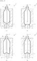
Figure 2 is an explanatory view showing a manufacturing process of a method for manufacturing a synthetic resin container of the embodiment of the invention. -
Figure 3 is an explanatory view showing a manufacturing process of the method for manufacturing a synthetic resin container of the embodiment of the invention. -
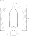
Figure 4 is an explanatory view showing a manufacturing process of the method for manufacturing a synthetic resin container of the embodiment of the invention. -
Figure 5 is an explanatory view showing a manufacturing process of a modification of the method for manufacturing a synthetic resin container of the embodiment of the invention. - Hereinbelow, a preferred embodiment of the invention will be described with reference to the drawings.
-
Figure 1 shows an outline of a blow molding device of the invention as one embodiment. Ablow molding device 1 shown inFigure 1 is intended to mold a bottomed tubular preform P into a predetermined container shape by blow molding. Theblow molding device 1 includes abody mold 2 formed of an openable split mold, abottom mold 3 incorporated on the bottom side of thebody mold 2 to be elevatable between a first blow molding position and a second blow molding position, astretch rod 4 that stretches the preform P in the axial direction, and apush rod 5 installed in a center part of thebottom mold 3 on the same axis as thestretch rod 4 and vertically movable in the axial direction. - Note that in
Figure 1 , a state where thebottom mold 3 is elevated to the second blow molding position is indicated by a chain double-dashed line. - The
stretch rod 4 included in theblow molding device 1 is configured to be vertically movable in the axial direction by an unillustrated drive unit. The movement of thestretch rod 4 is controlled such that when the downwardly movingstretch rod 4 reaches a bottommost point while stretching the preform P, thestretch rod 4 stops at a position avoiding interference with thebottom mold 3 in the second blow molding position as indicated by the chain double-dashed line inFigure 1 . In other words, the movement of thestretch rod 4 is controlled such that thestretch rod 4 is positioned above thebottom mold 3 and does not interfere with thebottom mold 3 when thebottom mold 3 is elevated to the second blow molding position. - The
push rod 5 included in theblow molding device 1 is configured to be vertically movable on the same axis as thestretch rod 4 by an unillustrated drive unit. The movement of thepush rod 5 is controlled such that thepush rod 5 protruding from thebottom mold 3 moves downward and retracts into thebottom mold 3 while supporting the stretching preform P separated from the stoppedstretch rod 4. - The upper and lower, right and left, and horizontal and vertical directions of the
blow molding device 1 defined herein are directions defined in the state shown inFigure 1 where thebottom mold 3 side is the lower side. - A method for manufacturing a synthetic resin container of the invention can be carried out appropriately by using the
blow molding device 1 described above. As one embodiment of the method, an example of producing a synthetic resin container by using theblow molding device 1 will be described while giving further detail on theblow molding device 1. - In the embodiment, first, as shown in
Figure 2 (a) , while thebottom mold 3 is lowered to the first blow molding position, thebody mold 2 is closed, and the heated and softened preform P ready to be blow molded is set in theblow molding device 1. - The preform P is made of thermoplastic resin, and is molded into the bottomed tubular shape in
Figure 2 (a) by injection molding or compression molding, for example. In the example ofFigure 2 (a) , the vicinity of an opening of the preform P is formed so as to serve as a mouth part of the container as it is. Examples of the thermoplastic resin include thermoplastic polyester such as polyethylene terephthalate, polybutylene terephthalate, polyethylene naphthalate, polylactic acid, and a copolymer of these substances, and a mixture of these resins or a mixture with other resins. While ethylene terephthalate-based thermoplastic polyester such as polyethylene terephthalate is particularly preferable, the embodiment is not limited thereto. - After the preform P is set in the
blow molding device 1, thepush rod 5 is moved upward and protruded from the bottom mold 3 (seeFigure 2 (b) ). At this time, the protrusion length of thepush rod 5 may be set appropriately depending on the stop position of thestretch rod 4. - As described earlier, the movement of the
stretch rod 4 is controlled such that thestretch rod 4 stops at a bottommost point which is a position where interference with thebottom mold 3 in the second blow molding position is avoided. When thepush rod 5 is protruded from thebottom mold 3, in the embodiment, thepush rod 5 is controlled to wait while protruding by a predetermined protrusion length from thebottom mold 3, so that the tip end of thepush rod 5 comes close to the tip end of thestretch rod 4 when thestretch rod 4 stops at the bottommost point. - Then, concurrently with or before or after an upward movement of the
push rod 5, thestretch rod 4 is moved downward and blow molding is started by blowing air into the preform P from an unillustrated blow air supply unit. Thus, the preform P is stretched not only in the axial direction (vertical direction) by thestretch rod 4, but also in the circumferential direction (lateral direction) by blow air (seeFigure 2 (c) and (d) ). - During this period, the preform P can be stretched uniformly by appropriately adjusting the lowering speed of the
stretch rod 4 and the blow air pressure. Moreover, although the preform P stretching while being supported by thestretch rod 4 can stretch without its stretching direction deviating from the axial direction, when thestretch rod 4 stops at the bottommost point, the stretching preform P loses the support by thestretch rod 4. If the stretching preform P having lost the support by thestretch rod 4 is further stretched in this state, the stretching direction of preform P may deviate from the axial direction. Deviation of the stretching direction from the axial direction causing the center of bottom of the preform P to stretch toward a position other than the center of thebottom mold 3 is undesirable from the viewpoint of uniform stretching of the preform P. - Hence, in the embodiment, the
push rod 5 is controlled to wait while protruding by a predetermined protrusion length from thebottom mold 3, so that thepush rod 5 can receive the stretching preform P having lost the support by thestretch rod 4. Then, the movement of thepush rod 5 is controlled such that after the stop of thestretch rod 4, thepush rod 5 moves downward and retracts into thebottom mold 3 while supporting the stretching preform P separated from the stopped stretch rod 4 (seeFigure 3 (e) and (f) ). - Accordingly, even after the stop of the
stretch rod 4, thepush rod 5 allows the stretching preform P to continue stretching until it reaches thebottom mold 3 in the first blow molding position, while suppressing deviation of the stretching direction of the stretching preform P from the axial direction. - Note that the speed of downward movement of the
push rod 5 during this period is appropriately adjusted so as to push the stretching preform P without hindering the stretching thereof, as a matter of course. - When the bottom side of the stretched preform P reaches the
bottom mold 3 in the first blow molding position, thebottom mold 3 is elevated to the second blow molding position by an unillustrated drive unit to push back and invert the bottom side of the stretched preform P, whereby the stretched preform P is formed according to the inner shape of thebody mold 2 and thebottom mold 3, and the stretched preform P is molded into a predetermined container shape (seeFigure 3 (g) ). Thus, it is possible to mold a container M sufficiently stretched and thinned on the container bottom side. - During this period, the
stretch rod 4 stays at a position avoiding interference with thebottom mold 3 in the second blow molding position, so that thebottom mold 3 and thestretch rod 4 do not interfere with each other. As a result, troubles such as scratches on the bottom of the molded container M and damaging of the mold member due to the interference between thebottom mold 3 and thestretch rod 4 can be avoided. - Thereafter, aftertreatment such as a cooling treatment is performed by blowing cooling air from unillustrated blowing nozzles provided in the stretch rod 4 (see
Figure 3 (h) ). Then, as shown inFigure 4 , thestretch rod 4 is moved upward, thebody mold 2 and thebottom mold 3 are opened, and the container M molded into a predetermined container shape is removed. - Note that the stop position of the
stretch rod 4 is appropriately adjusted also in consideration of preventing thestretch rod 4 from hindering the cooling treatment at this time. - As has been described, according to the embodiment, the
stretch rod 4 is stopped in a position avoiding interference with thebottom mold 3, so that interference between thebottom mold 3 and thestretch rod 4 can be avoided. Additionally, the movement of thepush rod 5 is controlled such that after the stop of thestretch rod 4, thepush rod 5 waiting while protruding by a predetermined protrusion length from thebottom mold 3 moves downward and retracts into thebottom mold 3 while supporting the stretching preform P separated from the stoppedstretch rod 4. Hence, deviation of the stretching direction of the preform P from the axial direction can be suppressed. In order to more surely suppress deviation of the stretching direction of the preform P from the axial direction, the movement of thepush rod 5 may be controlled in the following manner. -
Figure 5 is an explanatory view showing a manufacturing process of a modification of the embodiment. In the modification shown inFigure 5 , as in the aforementioned embodiment, after a preform P is set in a blow molding device 1 (seeFigure 5 (a) ), apush rod 5 is moved upward to protrude from abottom mold 3. At this time, thepush rod 5 is moved upward until the tip end of thepush rod 5 comes into contact with or comes close to the bottom of the preform P (seeFigure 5 (b) ). - Then, concurrently with or slightly after the upward movement of the
push rod 5, thestretch rod 4 is moved downward and blow molding is started by blowing air into the preform P from an unillustrated blow air supply unit. The resulting axial and circumferential stretching of the preform P is the same as the aforementioned embodiment (seeFigure 5 (c) and (d) ). During this period, the movement of thepush rod 5 is controlled such that thepush rod 5 protruding from thebottom mold 3 sandwiches the bottom side of the preform P together with thestretch rod 4, and moves downward in synchronization with thestretch rod 4. As a result, deviation of the stretching direction of the preform P from the axial direction can be suppressed more securely. - Then, the movement of the
push rod 5 is controlled such that after the stop of thestretch rod 4, thepush rod 5 moves downward and retracts into thebottom mold 3 while supporting the stretching preform P separated from the stoppedstretch rod 4, as in the case of the aforementioned embodiment. Since the following processes can also be carried out in the same manner as in the aforementioned embodiment, redundant descriptions are omitted. - While preferred embodiments of the invention have been described, the invention is not limited only to the embodiments, and various modifications can be made within the scope of the invention, as a matter of course.
- That is, the blow molding device of the invention may be configured in any way, as long as the blow molding device includes: the
body mold 2 formed of an openable split mold; thebottom mold 3 incorporated on the bottom side of thebody mold 2 to be elevatable between the first blow molding position and the second blow molding position; thestretch rod 4 configured to stretch the preform P in the axial direction; and thepush rod 5 installed in a center part of thebottom mold 3 on the same axis as thestretch rod 4 and vertically movable in the axial direction, the movement of thestretch rod 4 being controlled such that when the downwardly movingstretch rod 4 reaches the bottommost point while stretching the preform P, thestretch rod 4 stops at a position avoiding interference with thebottom mold 3 in the second blow molding position, and the movement of thepush rod 5 being controlled such that thepush rod 5 protruding from thebottom mold 3 moves downward and retracts into thebottom mold 3 while supporting the stretching preform P separated from the stoppedstretch rod 4. Matters other than these may be appropriately changed without being limited to the aforementioned embodiments, and matters described in the aforementioned embodiments may be appropriately selected and combined. - The method for manufacturing a synthetic resin container of the invention may include any steps, as long as the method includes the steps of: when blow molding is performed on the preform P set in the
blow molding device 1 in which thebody mold 2 is closed with thebottom mold 3 lowered to the first blow molding position, further stretching, while supporting with thepush rod 5, the stretching preform P separated from thestretch rod 4 stopped at the bottommost point; and when the bottom side of the stretched preform P reaches thebottom mold 3 in the first blow molding position, elevating thebottom mold 3 to the second blow molding position to push back and invert the bottom side of the stretched preform P, thereby forming the stretched preform P according to an inner shape of thebody mold 2 and thebottom mold 3 and molding the preform P into a predetermined container shape. Matters other than these may be appropriately changed without being limited to the aforementioned embodiments, and matters described in the aforementioned embodiments may be appropriately selected and combined. - The entire contents of the literature described in this specification and the Japanese patent application specification underlying the present Paris priority are incorporated herein.
- The invention may be used as a technique of manufacturing a synthetic resin container for various beverages, various seasonings, and the like.
-
- 1
- blow molding device
- 2
- body mold
- 3
- bottom mold
- 4
- stretch rod
- 5
- push rod
- P
- preform
- M
- container
Claims (4)
- A blow molding device that molds a bottomed tubular preform into a predetermined container shape by blow molding, the blow molding device comprising:a body mold formed of an openable split mold;a bottom mold incorporated on the bottom side of the body mold to be elevatable between a first blow molding position and a second blow molding position;a stretch rod configured to stretch the preform in the axial direction; anda push rod installed in a center part of the bottom mold on the same axis as the stretch rod and vertically movable in the axial direction, wherein:the movement of the stretch rod is controlled such that when the downwardly moving stretch rod reaches a bottommost point while stretching the preform, the stretch rod stops at a position avoiding interference with the bottom mold in the second blow molding position; andthe movement of the push rod is controlled such that the push rod protruding from the bottom mold moves downward and retracts into the bottom mold while supporting the stretching preform separated from the stopped stretch rod.
- The blow molding device according to claim 1, wherein
the movement of the push rod is controlled such that after the stop of the stretch rod, the push rod waiting while protruding by a predetermined protrusion length from the bottom mold moves downward and retracts into the bottom mold while supporting the stretching preform separated from the stopped stretch rod. - The blow molding device according to claim 1, wherein
the movement of the push rod is controlled such that the push rod protruding from the bottom mold sandwiches the bottom side of the preform together with the stretch rod and moves downward in synchronization with the stretch rod, and then after the stop of the stretch rod, the push rod moves downward and retracts into the bottom mold while supporting the stretching preform separated from the stopped stretch rod. - A method for manufacturing a synthetic resin container using the blow molding device according to any one of claims 1 to 3, the method comprising the steps of:when blow molding is performed on the preform set in the blow molding device in which the body mold is closed with the bottom mold lowered to the first blow molding position,further stretching, while supporting with the push rod, the stretching preform separated from the stretch rod stopped at a bottommost point; andwhen the bottom side of the stretched preform reaches the bottom mold in the first blow molding position, elevating the bottom mold to the second blow molding position to push back and invert the bottom side of the stretched preform, thereby forming the stretched preform according to an inner shape of the body mold and the bottom mold and molding the preform into a predetermined container shape.
Applications Claiming Priority (2)
| Application Number | Priority Date | Filing Date | Title |
|---|---|---|---|
| JP2016204396A JP2018065277A (en) | 2016-10-18 | 2016-10-18 | Blow molding device, and method for producing container made of synthetic resin using the same |
| PCT/JP2017/036975 WO2018074315A1 (en) | 2016-10-18 | 2017-10-12 | Blow molding device and method for manufacturing synthetic resin container using same |
Publications (2)
| Publication Number | Publication Date |
|---|---|
| EP3530430A1 true EP3530430A1 (en) | 2019-08-28 |
| EP3530430A4 EP3530430A4 (en) | 2020-05-27 |
Family
ID=62018579
Family Applications (1)
| Application Number | Title | Priority Date | Filing Date |
|---|---|---|---|
| EP17862119.9A Withdrawn EP3530430A4 (en) | 2016-10-18 | 2017-10-12 | BLOW MOLDING DEVICE AND METHOD FOR MANUFACTURING SYNTHETIC RESIN CONTAINER USING THE SAME |
Country Status (3)
| Country | Link |
|---|---|
| EP (1) | EP3530430A4 (en) |
| JP (1) | JP2018065277A (en) |
| WO (1) | WO2018074315A1 (en) |
Families Citing this family (4)
| Publication number | Priority date | Publication date | Assignee | Title |
|---|---|---|---|---|
| CN109454855B (en) * | 2018-12-30 | 2024-04-02 | 广东星联精密机械有限公司 | Axial bidirectional positioning stretching hollow blow molding mold |
| JP7776722B2 (en) * | 2021-02-25 | 2025-11-27 | キョーラク株式会社 | Double container and its manufacturing method |
| CN116214894B (en) * | 2023-03-29 | 2026-04-10 | 安徽银泰塑业有限公司 | A blow molding die for producing medical medicine bottles |
| JP7672757B1 (en) | 2024-09-05 | 2025-05-08 | 株式会社青木固研究所 | Method for molding hollow molded body, stretch rod and injection stretch blow molding machine used therein |
Family Cites Families (8)
| Publication number | Priority date | Publication date | Assignee | Title |
|---|---|---|---|---|
| JPS57210829A (en) * | 1981-06-22 | 1982-12-24 | Katashi Aoki | Molding of synthetic resin made bottle by biaxial stretch blow molding |
| JP4336425B2 (en) * | 1999-09-22 | 2009-09-30 | 北海製罐株式会社 | Blow molding method |
| JP2002067131A (en) * | 2000-08-30 | 2002-03-05 | Aoki Technical Laboratory Inc | Stretch blow molding method and blow mold |
| JP5140847B2 (en) * | 2007-04-02 | 2013-02-13 | 北海製罐株式会社 | Method for producing synthetic resin bottles |
| JP5453896B2 (en) * | 2009-04-23 | 2014-03-26 | 東洋製罐株式会社 | Stretch blow molding method and apparatus |
| JP5524688B2 (en) * | 2010-04-13 | 2014-06-18 | 北海製罐株式会社 | Blow molding method for synthetic resin bottles |
| AU2012217945B2 (en) * | 2011-02-15 | 2017-05-11 | Discma Ag | Reverse stretch rod for machine hygiene and processing |
| JP6079288B2 (en) * | 2013-02-15 | 2017-02-15 | 東洋製罐株式会社 | Method for producing a synthetic resin container |
-
2016
- 2016-10-18 JP JP2016204396A patent/JP2018065277A/en active Pending
-
2017
- 2017-10-12 WO PCT/JP2017/036975 patent/WO2018074315A1/en not_active Ceased
- 2017-10-12 EP EP17862119.9A patent/EP3530430A4/en not_active Withdrawn
Also Published As
| Publication number | Publication date |
|---|---|
| EP3530430A4 (en) | 2020-05-27 |
| JP2018065277A (en) | 2018-04-26 |
| WO2018074315A1 (en) | 2018-04-26 |
Similar Documents
| Publication | Publication Date | Title |
|---|---|---|
| JP6033779B2 (en) | Stretch rod system for fluid or hydraulic blow molding | |
| KR102264966B1 (en) | Injection molding mold of injection stretch blow molding machine, molding method of preform, molding method of preform, and container, and container | |
| US8962114B2 (en) | Compression molded preform for forming invertible base hot-fill container, and systems and methods thereof | |
| US12576574B2 (en) | Resin container manufacturing method | |
| US11472091B2 (en) | Two step blow molding unit, apparatus and method | |
| CN113453869B (en) | Method for manufacturing eccentric container and mold for temperature adjustment | |
| AU2011302329B2 (en) | Hydroblow preform design | |
| WO2018074315A1 (en) | Blow molding device and method for manufacturing synthetic resin container using same | |
| US11571847B2 (en) | Hollow article molding method and molding apparatus and hollow article | |
| JP6727760B2 (en) | Hollow container manufacturing method and blow molding apparatus | |
| JPH01133714A (en) | Manufacturing device for thermally fixed stretched plastic vessel | |
| JP2017177744A (en) | Container manufacturing method with liquid blow molding | |
| CN115666896A (en) | Method for manufacturing resin wide-mouth container, manufacturing device and resin wide-mouth container | |
| US9902103B2 (en) | Injection stretch blow molding method and apparatus for producing internally threaded containers | |
| EP4640406A1 (en) | Preform, method for producing resin container, and device for producing resin container | |
| JPH07205997A (en) | Method and apparatus for molding synthetic resin container with handle | |
| US12304131B2 (en) | Manufacturing method and manufacturing apparatus for delamination container | |
| CN114643693A (en) | Method and apparatus for blow molding containers comprising a movable bottom | |
| JP4748475B2 (en) | Injection molding preform | |
| JP6777960B1 (en) | Injection molding, preform molding method, and hollow body manufacturing method | |
| JP7106535B2 (en) | Injection mold and injection molding method for hollow article | |
| JPH06226830A (en) | Releasing method for preform | |
| KR102292713B1 (en) | Resin container manufacturing device and resin container manufacturing method using the same | |
| JP2001088201A (en) | Method and apparatus for forming container with handle, container with handle and preform with handle |
Legal Events
| Date | Code | Title | Description |
|---|---|---|---|
| STAA | Information on the status of an ep patent application or granted ep patent |
Free format text: STATUS: THE INTERNATIONAL PUBLICATION HAS BEEN MADE |
|
| PUAI | Public reference made under article 153(3) epc to a published international application that has entered the european phase |
Free format text: ORIGINAL CODE: 0009012 |
|
| STAA | Information on the status of an ep patent application or granted ep patent |
Free format text: STATUS: REQUEST FOR EXAMINATION WAS MADE |
|
| 17P | Request for examination filed |
Effective date: 20190415 |
|
| AK | Designated contracting states |
Kind code of ref document: A1 Designated state(s): AL AT BE BG CH CY CZ DE DK EE ES FI FR GB GR HR HU IE IS IT LI LT LU LV MC MK MT NL NO PL PT RO RS SE SI SK SM TR |
|
| AX | Request for extension of the european patent |
Extension state: BA ME |
|
| DAV | Request for validation of the european patent (deleted) | ||
| DAX | Request for extension of the european patent (deleted) | ||
| A4 | Supplementary search report drawn up and despatched |
Effective date: 20200424 |
|
| RIC1 | Information provided on ipc code assigned before grant |
Ipc: B29C 49/14 20060101AFI20200420BHEP Ipc: B29C 49/54 20060101ALN20200420BHEP Ipc: B29C 49/78 20060101ALI20200420BHEP Ipc: B29C 49/48 20060101ALN20200420BHEP Ipc: B29C 49/12 20060101ALI20200420BHEP Ipc: B29C 49/06 20060101ALN20200420BHEP |
|
| STAA | Information on the status of an ep patent application or granted ep patent |
Free format text: STATUS: THE APPLICATION HAS BEEN WITHDRAWN |
|
| 18W | Application withdrawn |
Effective date: 20201030 |