EP3530405A1 - Air extraction device, lubrication device, and air extraction method - Google Patents
Air extraction device, lubrication device, and air extraction method Download PDFInfo
- Publication number
- EP3530405A1 EP3530405A1 EP17890840.6A EP17890840A EP3530405A1 EP 3530405 A1 EP3530405 A1 EP 3530405A1 EP 17890840 A EP17890840 A EP 17890840A EP 3530405 A1 EP3530405 A1 EP 3530405A1
- Authority
- EP
- European Patent Office
- Prior art keywords
- lubricant
- conduit
- air
- supply conduit
- supply
- Prior art date
- Legal status (The legal status is an assumption and is not a legal conclusion. Google has not performed a legal analysis and makes no representation as to the accuracy of the status listed.)
- Granted
Links
Images


Classifications
-
- B—PERFORMING OPERATIONS; TRANSPORTING
- B01—PHYSICAL OR CHEMICAL PROCESSES OR APPARATUS IN GENERAL
- B01D—SEPARATION
- B01D19/00—Degasification of liquids
- B01D19/0005—Degasification of liquids with one or more auxiliary substances
-
- B—PERFORMING OPERATIONS; TRANSPORTING
- B23—MACHINE TOOLS; METAL-WORKING NOT OTHERWISE PROVIDED FOR
- B23Q—DETAILS, COMPONENTS, OR ACCESSORIES FOR MACHINE TOOLS, e.g. ARRANGEMENTS FOR COPYING OR CONTROLLING; MACHINE TOOLS IN GENERAL CHARACTERISED BY THE CONSTRUCTION OF PARTICULAR DETAILS OR COMPONENTS; COMBINATIONS OR ASSOCIATIONS OF METAL-WORKING MACHINES, NOT DIRECTED TO A PARTICULAR RESULT
- B23Q11/00—Accessories fitted to machine tools for keeping tools or parts of the machine in good working condition or for cooling work; Safety devices specially combined with or arranged in, or specially adapted for use in connection with, machine tools
- B23Q11/10—Arrangements for cooling or lubricating tools or work
- B23Q11/1015—Arrangements for cooling or lubricating tools or work by supplying a cutting liquid through the spindle
-
- B—PERFORMING OPERATIONS; TRANSPORTING
- B01—PHYSICAL OR CHEMICAL PROCESSES OR APPARATUS IN GENERAL
- B01D—SEPARATION
- B01D19/00—Degasification of liquids
- B01D19/0031—Degasification of liquids by filtration
-
- B—PERFORMING OPERATIONS; TRANSPORTING
- B01—PHYSICAL OR CHEMICAL PROCESSES OR APPARATUS IN GENERAL
- B01D—SEPARATION
- B01D19/00—Degasification of liquids
- B01D19/0042—Degasification of liquids modifying the liquid flow
-
- B—PERFORMING OPERATIONS; TRANSPORTING
- B01—PHYSICAL OR CHEMICAL PROCESSES OR APPARATUS IN GENERAL
- B01D—SEPARATION
- B01D19/00—Degasification of liquids
- B01D19/0063—Regulation, control including valves and floats
-
- B—PERFORMING OPERATIONS; TRANSPORTING
- B01—PHYSICAL OR CHEMICAL PROCESSES OR APPARATUS IN GENERAL
- B01F—MIXING, e.g. DISSOLVING, EMULSIFYING OR DISPERSING
- B01F23/00—Mixing according to the phases to be mixed, e.g. dispersing or emulsifying
- B01F23/20—Mixing gases with liquids
- B01F23/29—Mixing systems, i.e. flow charts or diagrams
-
- B—PERFORMING OPERATIONS; TRANSPORTING
- B01—PHYSICAL OR CHEMICAL PROCESSES OR APPARATUS IN GENERAL
- B01F—MIXING, e.g. DISSOLVING, EMULSIFYING OR DISPERSING
- B01F25/00—Flow mixers; Mixers for falling materials, e.g. solid particles
- B01F25/105—Mixing heads, i.e. compact mixing units or modules, using mixing valves for feeding and mixing at least two components
- B01F25/1051—Mixing heads, i.e. compact mixing units or modules, using mixing valves for feeding and mixing at least two components of the mixing valve type
-
- B—PERFORMING OPERATIONS; TRANSPORTING
- B23—MACHINE TOOLS; METAL-WORKING NOT OTHERWISE PROVIDED FOR
- B23Q—DETAILS, COMPONENTS, OR ACCESSORIES FOR MACHINE TOOLS, e.g. ARRANGEMENTS FOR COPYING OR CONTROLLING; MACHINE TOOLS IN GENERAL CHARACTERISED BY THE CONSTRUCTION OF PARTICULAR DETAILS OR COMPONENTS; COMBINATIONS OR ASSOCIATIONS OF METAL-WORKING MACHINES, NOT DIRECTED TO A PARTICULAR RESULT
- B23Q11/00—Accessories fitted to machine tools for keeping tools or parts of the machine in good working condition or for cooling work; Safety devices specially combined with or arranged in, or specially adapted for use in connection with, machine tools
- B23Q11/10—Arrangements for cooling or lubricating tools or work
- B23Q11/1038—Arrangements for cooling or lubricating tools or work using cutting liquids with special characteristics, e.g. flow rate, quality
-
- B—PERFORMING OPERATIONS; TRANSPORTING
- B23—MACHINE TOOLS; METAL-WORKING NOT OTHERWISE PROVIDED FOR
- B23Q—DETAILS, COMPONENTS, OR ACCESSORIES FOR MACHINE TOOLS, e.g. ARRANGEMENTS FOR COPYING OR CONTROLLING; MACHINE TOOLS IN GENERAL CHARACTERISED BY THE CONSTRUCTION OF PARTICULAR DETAILS OR COMPONENTS; COMBINATIONS OR ASSOCIATIONS OF METAL-WORKING MACHINES, NOT DIRECTED TO A PARTICULAR RESULT
- B23Q11/00—Accessories fitted to machine tools for keeping tools or parts of the machine in good working condition or for cooling work; Safety devices specially combined with or arranged in, or specially adapted for use in connection with, machine tools
- B23Q11/10—Arrangements for cooling or lubricating tools or work
- B23Q11/1038—Arrangements for cooling or lubricating tools or work using cutting liquids with special characteristics, e.g. flow rate, quality
- B23Q11/1046—Arrangements for cooling or lubricating tools or work using cutting liquids with special characteristics, e.g. flow rate, quality using a minimal quantity of lubricant
-
- B—PERFORMING OPERATIONS; TRANSPORTING
- B23—MACHINE TOOLS; METAL-WORKING NOT OTHERWISE PROVIDED FOR
- B23Q—DETAILS, COMPONENTS, OR ACCESSORIES FOR MACHINE TOOLS, e.g. ARRANGEMENTS FOR COPYING OR CONTROLLING; MACHINE TOOLS IN GENERAL CHARACTERISED BY THE CONSTRUCTION OF PARTICULAR DETAILS OR COMPONENTS; COMBINATIONS OR ASSOCIATIONS OF METAL-WORKING MACHINES, NOT DIRECTED TO A PARTICULAR RESULT
- B23Q11/00—Accessories fitted to machine tools for keeping tools or parts of the machine in good working condition or for cooling work; Safety devices specially combined with or arranged in, or specially adapted for use in connection with, machine tools
- B23Q11/10—Arrangements for cooling or lubricating tools or work
- B23Q11/1069—Filtration systems specially adapted for cutting liquids
-
- B—PERFORMING OPERATIONS; TRANSPORTING
- B23—MACHINE TOOLS; METAL-WORKING NOT OTHERWISE PROVIDED FOR
- B23Q—DETAILS, COMPONENTS, OR ACCESSORIES FOR MACHINE TOOLS, e.g. ARRANGEMENTS FOR COPYING OR CONTROLLING; MACHINE TOOLS IN GENERAL CHARACTERISED BY THE CONSTRUCTION OF PARTICULAR DETAILS OR COMPONENTS; COMBINATIONS OR ASSOCIATIONS OF METAL-WORKING MACHINES, NOT DIRECTED TO A PARTICULAR RESULT
- B23Q11/00—Accessories fitted to machine tools for keeping tools or parts of the machine in good working condition or for cooling work; Safety devices specially combined with or arranged in, or specially adapted for use in connection with, machine tools
- B23Q11/12—Arrangements for cooling or lubricating parts of the machine
- B23Q11/121—Arrangements for cooling or lubricating parts of the machine with lubricating effect for reducing friction
- B23Q11/122—Lubricant supply devices
-
- F—MECHANICAL ENGINEERING; LIGHTING; HEATING; WEAPONS; BLASTING
- F16—ENGINEERING ELEMENTS AND UNITS; GENERAL MEASURES FOR PRODUCING AND MAINTAINING EFFECTIVE FUNCTIONING OF MACHINES OR INSTALLATIONS; THERMAL INSULATION IN GENERAL
- F16N—LUBRICATING
- F16N39/00—Arrangements for conditioning of lubricants in the lubricating system
- F16N39/002—Arrangements for conditioning of lubricants in the lubricating system by deaeration
-
- F—MECHANICAL ENGINEERING; LIGHTING; HEATING; WEAPONS; BLASTING
- F16—ENGINEERING ELEMENTS AND UNITS; GENERAL MEASURES FOR PRODUCING AND MAINTAINING EFFECTIVE FUNCTIONING OF MACHINES OR INSTALLATIONS; THERMAL INSULATION IN GENERAL
- F16N—LUBRICATING
- F16N39/00—Arrangements for conditioning of lubricants in the lubricating system
- F16N39/06—Arrangements for conditioning of lubricants in the lubricating system by filtration
-
- F—MECHANICAL ENGINEERING; LIGHTING; HEATING; WEAPONS; BLASTING
- F16—ENGINEERING ELEMENTS AND UNITS; GENERAL MEASURES FOR PRODUCING AND MAINTAINING EFFECTIVE FUNCTIONING OF MACHINES OR INSTALLATIONS; THERMAL INSULATION IN GENERAL
- F16N—LUBRICATING
- F16N7/00—Arrangements for supplying oil or unspecified lubricant from a stationary reservoir or the equivalent in or on the machine or member to be lubricated
-
- F—MECHANICAL ENGINEERING; LIGHTING; HEATING; WEAPONS; BLASTING
- F16—ENGINEERING ELEMENTS AND UNITS; GENERAL MEASURES FOR PRODUCING AND MAINTAINING EFFECTIVE FUNCTIONING OF MACHINES OR INSTALLATIONS; THERMAL INSULATION IN GENERAL
- F16N—LUBRICATING
- F16N7/00—Arrangements for supplying oil or unspecified lubricant from a stationary reservoir or the equivalent in or on the machine or member to be lubricated
- F16N7/30—Arrangements for supplying oil or unspecified lubricant from a stationary reservoir or the equivalent in or on the machine or member to be lubricated the oil being fed or carried along by another fluid
- F16N7/32—Mist lubrication
-
- B—PERFORMING OPERATIONS; TRANSPORTING
- B01—PHYSICAL OR CHEMICAL PROCESSES OR APPARATUS IN GENERAL
- B01F—MIXING, e.g. DISSOLVING, EMULSIFYING OR DISPERSING
- B01F2101/00—Mixing characterised by the nature of the mixed materials or by the application field
- B01F2101/39—Mixing of ingredients for grease or lubricating compositions
-
- Y—GENERAL TAGGING OF NEW TECHNOLOGICAL DEVELOPMENTS; GENERAL TAGGING OF CROSS-SECTIONAL TECHNOLOGIES SPANNING OVER SEVERAL SECTIONS OF THE IPC; TECHNICAL SUBJECTS COVERED BY FORMER USPC CROSS-REFERENCE ART COLLECTIONS [XRACs] AND DIGESTS
- Y02—TECHNOLOGIES OR APPLICATIONS FOR MITIGATION OR ADAPTATION AGAINST CLIMATE CHANGE
- Y02P—CLIMATE CHANGE MITIGATION TECHNOLOGIES IN THE PRODUCTION OR PROCESSING OF GOODS
- Y02P70/00—Climate change mitigation technologies in the production process for final industrial or consumer products
- Y02P70/10—Greenhouse gas [GHG] capture, material saving, heat recovery or other energy efficient measures, e.g. motor control, characterised by manufacturing processes, e.g. for rolling metal or metal working
Definitions
- the present invention relates to an air bleeder, a lubricator, and a method for bleeding air. More particularly, the present invention relates to a technique of removing air through a lubricant supply conduit, through which lubricant is supplied to a mixing valve.
- a lubricator known in the art sends a fluid mixture of the lubricant and air to a lubrication target portion to reduce frictional resistance at the lubrication target portion.
- the lubricant and air are mixed in a mixing valve.
- the mixing valve receives lubricant through a lubricant supply conduit and receives air through an air supply conduit.
- the received lubricant and air are mixed together in the mixing valve, and the resulting fluid mixture is sent from the mixing valve toward the lubrication target portion.
- a related technique is disclosed in patent document 1, which recites a mixing valve that simplifies air bleeding work to significantly shorten the time necessary for the air bleeding work.
- the mixing valve recited in patent document 1 includes: a valve that is openable and closable by an intermittent oil feeding operation of a pump; an opening pin configured to keep the valve in open state; and an air bleeding button with which the opening pin is operated.
- the air bleeding button is pressed.
- oil intermittently sent under pressure from the pump continuously passes through the mixing valve and is discharged out of the mixing valve together with air bubbles in the mixing valve.
- Patent document 1 JP 2001-304489A
- an object of the present invention to provide: an air bleeder that reduces a burden on a worker and eliminates a waste of lubricant; a lubricator that is provided with the air bleeder; and a method for bleeding air.
- an air bleeder configured to remove air out of a lubricant supply conduit.
- the air bleeder includes: the lubricant supply conduit through which a lubricant is supplied to a mixing valve located in a machine tool; a lubricant tank in which the lubricant is stored; a branching portion located along the lubricant supply conduit; a return conduit connecting the branching portion and the lubricant tank to each other.
- the lubricant supply conduit includes: a first supply conduit connecting the lubricant tank and the branching portion to each other; and a second supply conduit connecting the branching portion and the mixing valve to each other. At the branching portion, an upper-stream end of the return conduit is located above an upper-stream end of the second supply conduit.
- a lubricator includes: the above-described air bleeder; the mixing valve configured to mix the lubricant and air together; an air supply conduit through which the air is supplied to the mixing valve; a fluid mixture supply conduit which is located between the mixing valve and a lubrication target portion of the machine tool and through which a fluid mixture of the lubricant and the air is supplied to the lubrication target portion.
- a method according to the present invention for bleeding air is a method for bleeding air using the above-described air bleeder.
- the method for bleeding air includes: opening the return conduit to form a circulation conduit including the lubricant tank, the first supply conduit, the branching portion, and the return conduit; and causing the lubricant to circulate through the circulation conduit with a flow of the lubricant in the second supply conduit stopped by the mixing valve.
- the present invention provides: an air bleeder that reduces a burden on a worker and eliminates a waste of lubricant; a lubricator that is provided with the air bleeder; and a method for bleeding air.
- Embodiments of the present invention will be described by referring to an air bleeder 1, a lubricator 100, which is provided with the air bleeder 1, and a method for bleeding air, with reference to the drawings. It is noted that in the following description of the embodiments, identical reference numerals are used to denote identical portions, members, or components having identical functions, and redundant description of identical portions, members, or components will be omitted.
- FIG. 1 schematically illustrates the air bleeder 1 according to the first embodiment.
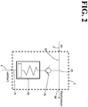
- FIG. 2 schematically illustrates an exemplary internal structure of a mixing valve 2.
- the air bleeder 1 is an air bleeder that removes contaminated air out of a lubricant supply conduit 5, which supplies lubricant A to the mixing valve 2, which is located in a machine tool.
- the air bleeder 1 includes a lubricant tank 4, the lubricant supply conduit 5, a branching portion 61, and a return conduit 64. It is noted that as illustrated in FIG. 1 , the air bleeder 1 may include a switch valve 67 and/or a lubricant supply pump 71.
- the mixing valve 2 mixes the lubricant A and air together.
- a known mixing valve may be employed.
- the mixing valve 2 includes: a lubricant conduit 21, which is connected to the lubricant supply conduit 5; an air conduit 22, which is connected to an air supply conduit 3; a metering valve 23; and a check valve 24.
- the metering valve 23 of the mixing valve 2 is supplied the lubricant A through the lubricant supply conduit 5 and the lubricant conduit 21.
- the metering valve 23 intermittently ejects a predetermined amount of the lubricant A.
- the metering valve 23 does not turn into open state unless the pressure of the lubricant conduit 21 exceeds a predetermined threshold. That is, the metering valve 23 is kept in closed state while the lubricant supply pump 71 is not operating.
- the air conduit 22 is continuously supplied air from the air supply conduit 3.
- the air supplied from the air conduit 22 and the predetermined amount of the lubricant A intermittently supplied from the metering valve 23 are mixed (subjected to mixing) together at a mixture region 25.
- the air and the lubricant A are mixed together into a fluid mixture, which is discharged through a discharge orifice 26 of the mixing valve 2.
- the air supply conduit 3 is a conduit through which air is supplied to the mixing valve 2.
- the air supply conduit 3 connects an air supply source 31, such as a compressor, and the mixing valve 2 to each other.
- a filter 35 which removes foreign matter contaminating air, may be provided along the air supply conduit 3.
- the lubricant tank 4 is where the lubricant A is stored.
- the supply of the lubricant A from the lubricant tank 4 to the lubricant supply conduit 5 is implemented using the lubricant supply pump 71.
- the lubricant supply pump 71 is located along the lubricant supply conduit 5 (more specifically, a first supply conduit 51, described later).
- the lubricant supply pump 71 is driven by a motor M.
- An example of the motor M is an electric motor.
- the lubricant supply conduit 5 is a conduit through which the lubricant A is supplied to the mixing valve 2.
- the lubricant supply conduit 5 includes the first supply conduit 51 and a second supply conduit 52.
- the first supply conduit 51 is an upper-stream conduit that connects the lubricant tank 4 and the branching portion 61 to each other.
- the second supply conduit 52 is a lower-stream conduit that connects the branching portion 61 and the mixing valve 2 to each other.
- the term "upper-stream” refers to the upstream side of the direction in which the lubricant A flows
- the term “lower-stream” refers to the downstream side of the direction in which the lubricant A flows.
- the first supply conduit 51 may be a single conduit (flexible conduit or rigid conduit) or may be a combination of a plurality of conduits (flexible conduits or rigid conduits) connected to each other.
- the second supply conduit 52 may be a single conduit (flexible conduit or rigid conduit) or may be a combination of a plurality of conduits (flexible conduits or rigid conduits) connected to each other.
- the branching portion 61 is a branching portion located along the lubricant supply conduit 5.
- the branching portion 61 causes the first supply conduit 51 to branch at least into the second supply conduit 52 and the return conduit 64.
- the switch valve 67 described later, is in closed state (which keeps the return conduit 64 in closed state)
- the lubricant A supplied from the lubricant tank 4 is supplied to the mixing valve 2 through the first supply conduit 51 and the second supply conduit 52.
- the switch valve 67 described later, is in open state (which keeps the return conduit 64 in open state)
- the lubricant A supplied from the lubricant tank 4 returns to the lubricant tank 4 through the first supply conduit 51 and the return conduit 64.
- the return conduit 64 is a conduit that connects the branching portion 61 and the lubricant tank 4 to each other.
- the return conduit 64 may be a single conduit (flexible conduit or rigid conduit) or may be a combination of a plurality of conduits (flexible conduits or rigid conduits) connected to each other.
- the lubricant tank 4, the first supply conduit 51, the branching portion 61, and the return conduit 64 form a circulation conduit CF.
- the switch valve 67 is a valve that opens and closes the return conduit 64.
- the switch valve 67 is an openable and closable valve located along the return conduit 64.
- the openable and closable valve (the switch valve 67) is in closed state, the return conduit 64 is closed.
- the openable and closable valve (the switch valve 67) is in open state, the return conduit 64 is open.
- the switch valve 67 may be located at the branching portion 61.
- a multi-directional valve such as a three-way valve may be employed.
- the multi-directional valve for example, three-way valve
- the multi-directional valve closes the return conduit 64.
- the multi-directional valve for example, three-way valve
- the multi-directional valve for example, three-way valve
- the switch valve 67 is preferably located along the return conduit 64, instead of at the branching portion 61.
- the switch valve 67 is located along the return conduit 64, even if air is trapped in the switch valve 67 itself, there is no or minimal possibility of the trapped air flowing toward the mixing valve 2.
- the switch valve 67 may be omitted. In this case, it is possible to open and close the return conduit 64 using a tool (such as a clip) separate from the air bleeder 1.
- the upper-stream end, 64a, of the return conduit 64 at the branching portion 61 is located above the upper-stream end, 52a, of the second supply conduit 52 at the branching portion 61.
- This configuration ensures that even if air enters the first supply conduit 51, the contaminated air moves to the return conduit 64, which is located above the second supply conduit 52, at the branching portion 61. Thus, the contaminated air is prevented from reaching the mixing valve 2 through the second supply conduit 52.
- air may possibly enter the first supply conduit 51 if the mixing valve 2 is kept in not-operating state for maintenance or replacement of the components (such as the lubricant tank 4) connected to the first supply conduit 51, which is located on the upper-stream side of the mixing valve, or if the lubricant supply pump 71 is kept in un-driven state for a long period of time.
- the air that has entered the first supply conduit 51 moves to the return conduit 64, which is located above the second supply conduit 52, at the branching portion 61.
- the contaminated air is prevented from reaching the mixing valve 2 through the second supply conduit 52.
- a lower-stream end portion 64b of the return conduit 64 is connected to the lubricant tank 4. This configuration causes the air that has entered the first supply conduit 51 to be sent to the lubricant tank 4 through the return conduit 64. In this manner, the air is removed out of the first supply conduit 51 (and the circulation conduit CF).
- the removal of the air is implemented by, for example, driving the lubricant supply pump 71 with the return conduit 64 in open state (for example, with the closed state of the return conduit 64 released by the switch valve 67).
- the return conduit 64 is in open state, the internal pressure of the second supply conduit 52 does not exceed the operating pressure of the mixing valve 2 (more specifically, the operating pressure of the metering valve 23), even if the lubricant supply pump 71 is driven. That is, even if the lubricant supply pump 71 is driven, the mixing valve 2 prevents the movement of the lubricant A, ensuring that the air-contaminated lubricant A does not move through the second supply conduit 52.
- the mixing valve 2 serves as a closed-state valve during the operation of removing the contaminated air that has entered the first supply conduit 51.
- This configuration reliably prevents the air-contaminated lubricant A from moving from the branching portion 61 toward the second supply conduit 52 during the operation of removing the contaminated air.
- the worker in performing the operation of removing contaminated air, the worker may release the closed state of the return conduit 64, and then drive the lubricant supply pump 71. Also in the example illustrated in FIG. 1 , in the operation of removing the contaminated air, the lubricant A returns to the lubricant tank 4, instead of being discharged out of the air bleeder 1. This configuration eliminates a waste of the lubricant A and prevents the environment of the air bleeder 1 and the mixing valve 2 from being contaminated by the lubricant A.
- the upper-stream end 64a of the return conduit 64 is connected to an upper portion of the branching portion 61, and an upper-stream end portion 641 of the return conduit 64 extends upward from the branching portion 61.
- the upper-stream end portion 641 of the return conduit 64 serves as a buffer space to receive air. For example, assume that air remains in the first supply conduit 51 due to an insufficient operation of removing contaminated air. In this case, if the return conduit 64 is closed and the lubricant supply pump 71 is driven, the lubricant A flows through the first supply conduit 51 and the second supply conduit 52.
- the air bleeder 1 Assume that the air bleeder 1 according to the first embodiment is not employed and that work of removing air that has entered the lubricant supply conduit is performed by operating the mixing valve.
- the amount of lubricant sent from the mixing valve toward a lubrication target portion per unit time is small. Therefore, when the work of removing contaminated air out of the lubricant supply conduit is performed while the mixing valve is kept operating, the work takes a long period of time.
- it is necessary to reliably remove air that has entered the lubricant conduit of the mixing valve it is necessary to perform, at least 10 times, the work of adjusting the mixing valve into different postures and supplying oil to the lubricant conduit at each posture.
- the mixing valve in order to remove air completely out of the mixing valve itself, it is necessary to confirm that no air bubbles are coming out of a plug of the mixing valve. Thus, the air bleeding work requires some level of proficiency. Further, there needs to be a worker dedicated to adjusting the posture of the mixing valve and another worker dedicated to activating and stopping the pump. Additionally, the lubricant in the lubricant supply conduit is discharged out of the mixing valve, which is a waste of the lubricant. Further, it is possible for the discharged lubricant to contaminate the environment of the mixing valve.
- machine tools are huge structures fixed in factories, and bodies of machine tools cannot be easily moved to change positions for daily inspection or periodic maintenance.
- the worker needs to remove a maintenance cover or a similar object on a fixed machine tool, approach a maintenance target portion, and work on the maintenance target portion.
- a mixing valve that supplies lubricant to a lubrication target portion of a machine tool is located inside the machine tool or above the machine tool. Therefore, the work of removing air out of the lubricant supply conduit by operating the mixing valve involves work inside the machine tool or above the machine tool.
- the air bleeding work using the mixing valve is quite a burden on the worker from a work environment standpoint.
- the air bleeder advantageously takes the burden off the worker who maintains and manages a machine tool.
- the air bleeder 1 may include a foreign matter removal filter 74, which is located along the first supply conduit 51.
- the air bleeder 1 includes the foreign matter removal filter 74, foreign matter is prevented from entering the mixing valve 2.
- foreign matter is prevented from entering the fluid mixture ejected from the mixing valve 2.
- This configuration prevents foreign matter otherwise contained in the fluid mixture from damaging the supply target of the lubricant A (that is, lubrication target portion).
- the foreign matter removal filter 74's function of preventing foreign matter contamination can be maintained.
- air may possibly enter the first supply conduit 51.
- the branching portion 61 is located on the lower-stream side of the foreign matter removal filter 74, and, at the branching portion 61, the upper-stream end 64a of the return conduit 64 is located above the upper-stream end 52a of the second supply conduit 52.
- a first foreign matter removal filter 74a (more specifically, line filter) is located along the first supply conduit 51 (more specifically, at an intermediate portion of the first supply conduit 51).
- the first foreign matter removal filter 74a prevents foreign matter that has entered the first supply conduit 51 from reaching the mixing valve 2 through the second supply conduit 52.
- the first foreign matter removal filter 74a is positioned on the lower-stream side of the lubricant supply pump 71.
- This configuration enables the first foreign matter removal filter 74a to remove not only the foreign matter contained in the lubricant A but also foreign matter generated as a result of operation of the lubricant supply pump 71 (an example of such foreign matter is a removed part of the outer layer of the lubricant supply pump 71, a removed part of the outer layer of the first supply conduit 51, or a removed part of the outer layer of a second foreign matter removal filter 74b, described later).
- the first foreign matter removal filter 74a is located outside the lubricant tank 4. With this configuration, the work of replacing the first foreign matter removal filter 74a or a part of the first foreign matter removal filter 74a is comparatively easy.
- the second foreign matter removal filter 74b (more specifically, suction filter) is located at the base end of the first supply conduit 51.
- the second foreign matter removal filter 74b prevents foreign matter contained in the lubricant tank 4 from entering the first supply conduit 51.
- the second foreign matter removal filter 74b is located in the lubricant tank 4. With this configuration, the second foreign matter removal filter 74b is difficult to replace as compared with the first foreign matter removal filter 74a. Because of this difficulty, the second foreign matter removal filter 74b may, in some cases, be left un-replaced for a long period of time. In this case, a part of the outer layer of the second foreign matter removal filter 74b may be removed, resulting in foreign matter.
- the second foreign matter removal filter 74b is preferably such a filter that partial removal of the outer layer is difficult to occur (an example of such filter is a wire-mesh type filter).
- the second foreign matter removal filter 74b may be rougher than the first foreign matter removal filter 74a. In this case, the second foreign matter removal filter 74b removes comparatively large-size foreign matter. This prevents clogging of the first foreign matter removal filter 74a and reduces the frequency of replacement of the first foreign matter removal filter 74a.
- first foreign matter removal filter 74a may be omitted.
- the lubricant tank 4 includes a lubricant inlet orifice 41 and a lid member 42, which closes the lubricant inlet orifice 41.
- the lubricant inlet orifice 41 may be provided with an inlet orifice filter 43 (for example, a filter that removes impurities having particle diameters of 400 ⁇ m or greater), which prevents foreign matter from entering the lubricant tank 4 through the lubricant inlet orifice 41.
- the second foreign matter removal filter 74b is integral to the lubricant supply pump 71. This configuration enables the second foreign matter removal filter 74b and the lubricant supply pump 71 to be handled as a single unit that can be more easily removed from the lubricant tank 4 for maintenance purposes.
- the upper-stream end of the first supply conduit 51 is connected to the lubricant tank 4, and the lower-stream end of the first supply conduit 51 is connected to the branching portion 61.
- the first supply conduit 51 may be made of a resin material or a metal material. Also, the first supply conduit 51 may be a flexible conduit or a rigid conduit, or may have a rigid part forming an inner conduit. Alternatively, the first supply conduit 51 may be a combination of the foregoing.
- a lower-stream end portion 511 of the first supply conduit 51 is an upward conduit forming an upward flow toward the branching portion 61. Since the lower-stream end portion 511 is an upward conduit, contaminated air is prone to move upward at the branching portion 61. This makes removal of contaminated air more reliable through the return conduit 64. It is noted that the upward conduit may be a vertically upward conduit or an inclined upward conduit.
- the upper-stream end 64a of the return conduit 64 is connected to the branching portion 61, and the lower-stream end portion 64b of the return conduit 64 is connected to the lubricant tank 4.
- the return conduit 64 may be made of a resin material or a metal material. Also, the return conduit 64 may be a flexible conduit or a rigid conduit, or may have a rigid part forming an inner conduit. Alternatively, the return conduit 64 may be a combination of the foregoing.
- the upper-stream end portion 641 of the return conduit 64 is an upward conduit forming an upward flow from the branching portion 61. Since the upper-stream end portion 641 is an upward conduit, contaminated air that has entered the upper-stream end portion 641 through the branching portion 61 is prevented from returning to the branching portion 61. It is noted that the upward conduit may be a vertically upward conduit or an inclined upward conduit.
- the angle between the lower-stream end portion 511 and the upper-stream end portion 641 is preferably an obtuse angle, more preferably 120 degrees or greater, further more preferably 150 degrees or greater, and still further more preferably 180 degrees or greater.
- the switch valve 67 which opens and closes the return conduit, may be a manual valve, an electric valve, or an electromagnetic valve.
- the switch valve 67 includes a handle 671.
- the switch valve 67 is an electric valve or an electromagnetic valve, the switch valve 67 includes a driver 672.
- the driver 672 is connected to a controller (not illustrated in FIG. 1 ) in a signal-transmittable manner.
- the upper-stream end 52a of the second supply conduit 52 is connected to the branching portion 61, and the lower-stream end of the second supply conduit 52 is connected to the mixing valve 2.
- the second supply conduit 52 may be made of a resin material or a metal material.
- the second supply conduit 52 may be a flexible conduit or a rigid conduit, or may have a rigid part forming an inner conduit.
- the second supply conduit 52 may be a combination of the foregoing. It is noted, however, that from the viewpoint of greater degree of freedom of arrangement of the lubricant tank 4 and other components, the second supply conduit 52 is preferably a flexible conduit.
- the branching portion 61 may be a manifold-type branching portion.
- This manifold-type branching portion includes a lubricant reservoir. To the lubricant reservoir, the first supply conduit 51, the second supply conduit 52, and the return conduit 64 are connected.
- the branching portion 61 may be a piping joint.
- the first supply conduit 51, the second supply conduit 52, and the return conduit 64 are connected to each other via the piping joint, and the piping joint serves as the branching portion 61.
- the lubricant tank 4, the lubricant supply pump 71, the foreign matter removal filter 74, the branching portion 61, the first supply conduit 51, the return conduit 64, and the switch valve 67 may form a single transportable unit.
- the second embodiment is an embodiment related to a lubricator 100.
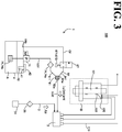
- FIG. 3 schematically illustrates the lubricator 100 according to the second embodiment.
- the lubricator 100 according to the second embodiment includes: the air bleeder 1 according to the first embodiment; a mixing valve 2; an air supply conduit 3; and fluid mixture supply conduits 110, which supplies a fluid mixture of lubricant A and air to lubrication target portions 120.
- the air bleeder 1 according to the second embodiment is similar to the air bleeder 1 according to the first embodiment. In light of this, redundant description of configurations of the air bleeders 1 will be omitted.
- the fluid mixture supply conduits 110 is located between the mixing valve 2 and the lubrication target portions 120, which are located in a machine tool B.
- the number of the fluid mixture supply conduits 110 may be one, two, or four or more.
- examples of the machine tool B include a machining center, a lathe, and a combined machine.
- the lubrication target portions 120 are bearings 122 of a spindle 121 of the machine tool B.
- the lubrication target portions 120 may be at other than the spindle 121 insofar as the lubrication target portions 120 are where a fluid mixture of the lubricant A and air is supplied.
- air may possibly enter the first supply conduit 51 during maintenance or replacement of the components located on the upper-stream side of the branching portion 61 (such as the lubricant tank 4, the foreign matter removal filter 74, and the lubricant supply pump 71).
- the lubricator 100 according to the second embodiment includes the air bleeder 1 according to the first embodiment, contaminated air is easily removed out of the first supply conduit 51.
- the lubricator 100 according to the second embodiment includes the foreign matter removal filter 74 on the first supply conduit 51, foreign matter that has entered the first supply conduit 51 is removed.
- the second embodiment provides advantageous effects similar to the advantageous effects of the first embodiment.
- the mixing valve 2's function of supplying a predetermined amount of the lubricant A is undermined.
- the mixing valve 2 and the lubrication target portions 120 of the machine tool B are connected to each other via the fluid mixture supply conduits 110.
- the spindle 121 may fail. If the spindle 121 of the machine tool fails, large-scale repair work is necessitated.
- the second embodiment even if air enters the first supply conduit 51 during maintenance or replacement of the components located on the upper-stream side of the branching portion 61 (such as the lubricant tank 4, the foreign matter removal filter 74, and the lubricant supply pump 71), the contaminated air is easily removed out of the lubricant supply conduit 5 (more specifically, the first supply conduit 51). Therefore, in the second embodiment, the function of supplying a predetermined amount of the lubricant A is not undermined, and the reduction in the frictional resistance of the bearings 122 is not insufficient. Also, the risk of a failed spindle 121 is reduced. In the second embodiment, the air bleeding work of removing contaminated air out of the first supply conduit 51 can be easily performed.
- the air bleeding work is expected to be performed more frequently after maintenance work (for example, the work of replacing the foreign matter removal filter 74 or a part of the foreign matter removal filter 74) and maintenance work of the foreign matter removal filter 74.
- maintenance work for example, the work of replacing the foreign matter removal filter 74 or a part of the foreign matter removal filter 74
- maintenance work for example, the work of replacing the foreign matter removal filter 74 or a part of the foreign matter removal filter 74
- the length of each of the fluid mixture supply conduits 110 which connect the mixing valve 2 and the lubrication target portions 120 to each other, needs to be set at a moderate length. If the length of each fluid mixture supply conduit 110 is too small, the lubricant A may be insufficiently dispersed in the air in the fluid mixture supply conduit 110. If the length of each fluid mixture supply conduit 110 is too large, there occurs a large time lag between the start of operation of the mixing valve 2 and the timing at which the fluid mixture is ejected to the lubrication target portions 120.
- the mixing valve 2 is, in many cases, located above the machine tool B or inside the machine tool B.
- the mixing valve 2 in removing air that has entered the lubricant supply conduit, it was necessary to change the mixing valve into different postures and perform air bleeding work at each posture. This caused a greatly burdensome work environment for the worker who performed the air bleeding work.
- the work of removing air that has entered the lubricant supply conduit can be performed around the machine tool B. This makes the work environment of the worker who performs the air bleeding work a better work environment.
- the length of the second supply conduit 52 which connects the branching portion 61 and the mixing valve 2 to each other, is preferably greater than the length of the first supply conduit 51, which connects the lubricant tank 4 and the branching portion 61 to each other.
- This is from the viewpoint of securing a sufficiently long distance between the mixing valve 2, which is located, for example, above the machine tool B or inside the machine tool B, and the foreign matter removal filter 74 and other components located around the machine tool B, and the viewpoint of arranging the branching portion 61, the foreign matter removal filter 74, the switch valve 67, and the lubricant tank 4 in a compact manner.
- the length of the lubricant supply conduit 5 (more specifically, the length of the second supply conduit 52) is preferably greater than the length of each fluid mixture supply conduit 110. This is from the viewpoint of securing a sufficiently long distance between the mixing valve 2, which is located, for example, above the machine tool B or inside the machine tool B, and the foreign matter removal filter 74 and other components located around the machine tool B.
- the lubricant tank 4, the foreign matter removal filter 74, and the switch valve 67 (and the handle 671 of the switch valve 67) are located, for example, at positions around the machine tool B and at a height within reach of the hand of the worker. This is from considerations including accessibility for the worker.
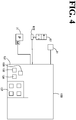
- FIG. 4 schematically illustrates a part of the lubricator 100 including the controller 130, the lubricant supply pump 71, the switch valve 67, and the air supply source 31.
- the controller 130 controls operation of the lubricant supply pump 71, operation of the switch valve 67, and operation of the air supply source 31.
- the controller 130 and the lubricant supply pump 71 are connected to each other in a control-signal transmittable manner.
- This connection may be a wired connection or a wireless connection.
- the controller 130 and the switch valve 67 are connected to each other in a control-signal transmittable manner.
- This connection may be a wired connection or a wireless connection.
- the controller 130 and the air supply source 31 are connected to each other in a control-signal transmittable manner.
- This connection may be a wired connection or a wireless connection.
- the air supply source 31, which is controlled by the controller 130 is an openable and closable valve located on the air supply conduit 3.
- the controller 130 includes a drive switch 132 for the lubricant supply pump 71 and an operation switch 134 for the switch valve 67.
- the controller 130 may include an operation switch 135 for the air supply source 31.
- the drive switch 132 for the lubricant supply pump 71, the operation switch 134 for the switch valve 67, and the operation switch 135 for the air supply source 31 are located on an operation panel 131 of the controller 130.
- the air bleeding work of bleeding air out of the first supply conduit 51 can be performed by merely operating the drive switch 132 and the operation switch 134, which are located in the controller 130 (more specifically, on the operation panel 131). This configuration reduces the work burden on the worker.
- the operation panel 131 may include an operation switch 137 for the machine tool.
- the operation switch 137 for the machine tool, the drive switch 132, the operation switch 134, and the operation switch 135 are located adjacent to each other. In this case, the worker is able to, without moving, check that the machine tool B has stopped driving and perform the air bleeding work of bleeding air out of the first supply conduit 51.
- the operation panel 131 may be an operation panel dedicated to the lubricator 100.
- the drive switch 132 may be directly mounted on the lubricant supply pump 71
- the operation switch 134 may be directly mounted on the switch valve 67
- the operation switch 135 may be directly mounted on the air supply source 31.
- FIG. 5 is a flowchart of an exemplary method according to the third embodiment for bleeding air.
- FIG. 6 is a flowchart of an exemplary method according to the third embodiment for bleeding air.
- the method according to the third embodiment for bleeding air is a method for bleeding air using the air bleeder 1 according to the first embodiment or the lubricator 100 according to the second embodiment.
- the method for bleeding air includes a circulation conduit forming step and an air bleeding step.
- the switch valve 67 and related components open the return conduit 64.
- the lubricant tank 4 the first supply conduit 51, the branching portion 61, and the return conduit 64 form the circulation conduit CF.
- the lubricant A is caused to circulate through the circulation conduit CF.
- the lubricant A containing contaminated air is caused to return to the lubricant tank 4. In this manner, the contaminated air is removed out of the first supply conduit 51.
- the air bleeding step is performed with the flow of the lubricant A through the second supply conduit 52 being stopped by the mixing valve 2. More specifically, when the return conduit 64 is in open state, the internal pressure of the second supply conduit 52 does not exceed the operating pressure of the mixing valve 2 (more specifically, the operating pressure of the metering valve 23). This ensures that the mixing valve 2 does not accept the lubricant A from the second supply conduit 52.
- air is removed out of the first supply conduit 51 merely by operating the switch valve 67 and related components to turn the return conduit 64 into open state and then causing the lubricant A to circulate through the circulation conduit CF.
- This configuration reduces the work burden on the worker who performs the air bleeding work.
- the above configuration also shortens the work time.
- step ST1 supply of the lubricant A and air to the mixing valve 2 is stopped.
- the supply of the lubricant A is stopped by, for example, stopping the operation of the lubricant supply pump 71 and stopping the operation of the air supply source 31.
- the operation of the lubricant supply pump 71 may be stopped by operating the drive switch 132 on the operation panel 131.
- the supply of air may be stopped by operating the operation switch 135 on the operation panel 131.
- the switch valve 67 opens the return conduit 64.
- the second step ST2 corresponds to the above-described circulation conduit forming step.
- the second step ST2 may be performed by operating the operation switch 134 on the operation panel 131.
- the switch valve 67 is an openable and closable valve
- the switch valve 67's operation of opening the return conduit 64 corresponds to the switch valve 67's turning into open state.
- the switch valve 67 is a multi-directional valve (for example, three-way valve)
- the switch valve 67's operation of opening the return conduit 64 corresponds to such an operation that the switch valve 67, which is a multi-directional valve, turns the first supply conduit 51 and the return conduit 64 into mutually connected state.
- the lubricant supply pump 71 is driven. Upon driving of the lubricant supply pump 71, the lubricant A is caused to circulate through the circulation conduit CF. That is, the third step ST3 corresponds to the above-described air bleeding step.
- the third step ST3 may be performed by operating the drive switch 132 on the operation panel 131. After the air bleeding step ends, the driving of the lubricant supply pump 71 is stopped.
- the switch valve 67 closes the return conduit 64.
- the fourth step ST4 may be performed by operating the operation switch 134 on the operation panel 131.
- the switch valve 67's operation of closing the return conduit 64 corresponds to the switch valve 67's turning into closed state.
- the switch valve 67 is a multi-directional valve (for example, three-way valve)
- the switch valve 67's operation of closing the return conduit 64 corresponds to such an operation that the switch valve 67, which is a multi-directional valve, turns the first supply conduit 51 and the second supply conduit 52 into mutually connected state.
- the lubricator 100 is able to perform the operation of supplying lubricant to the lubrication target portions 120.
- the supply of the lubricant A and air to the mixing valve 2 is caused to start, causing a fluid mixture containing the lubricant A to be supplied from the mixing valve 2 to the lubrication target portions 120.
- the supply of the lubricant A to the lubrication target portions 120 is performed by, for example, starting the operation of the lubricant supply pump 71 and starting the operation of the air supply source 31.
- the operation of the lubricant supply pump 71 may be caused to start by operating the drive switch 132.
- the supply of air may be caused to start by operating the operation switch 135.
- the air bleeding work is performed simply by operating the switch valve 67 and/or the lubricant supply pump 71.
- This configuration reduces the work burden on the worker who performs the air bleeding work.
- the above configuration also shortens the work time.
- the operation switch 134, with which the switch valve 67 is driven, and the drive switch 132, with which the lubricant supply pump 71 is driven are located adjacent to each other (for example, when the operation switch 134 and the drive switch 132 are located on the operation panel 131), the worker is able to perform the air bleeding work without moving.
Landscapes
- Engineering & Computer Science (AREA)
- General Engineering & Computer Science (AREA)
- Mechanical Engineering (AREA)
- Chemical & Material Sciences (AREA)
- Chemical Kinetics & Catalysis (AREA)
- Fluid Mechanics (AREA)
- Physics & Mathematics (AREA)
- Combustion & Propulsion (AREA)
- Oil, Petroleum & Natural Gas (AREA)
- Nozzles (AREA)
- Auxiliary Devices For Machine Tools (AREA)
- Rolling Contact Bearings (AREA)
- Fluid-Pressure Circuits (AREA)
Abstract
Description
- The present invention relates to an air bleeder, a lubricator, and a method for bleeding air. More particularly, the present invention relates to a technique of removing air through a lubricant supply conduit, through which lubricant is supplied to a mixing valve.
- A lubricator known in the art sends a fluid mixture of the lubricant and air to a lubrication target portion to reduce frictional resistance at the lubrication target portion. The lubricant and air are mixed in a mixing valve. The mixing valve receives lubricant through a lubricant supply conduit and receives air through an air supply conduit. The received lubricant and air are mixed together in the mixing valve, and the resulting fluid mixture is sent from the mixing valve toward the lubrication target portion.
- A related technique is disclosed in
patent document 1, which recites a mixing valve that simplifies air bleeding work to significantly shorten the time necessary for the air bleeding work. The mixing valve recited inpatent document 1 includes: a valve that is openable and closable by an intermittent oil feeding operation of a pump; an opening pin configured to keep the valve in open state; and an air bleeding button with which the opening pin is operated. For the air bleeding work to be performed, the air bleeding button is pressed. When the air bleeding button is pressed, oil intermittently sent under pressure from the pump continuously passes through the mixing valve and is discharged out of the mixing valve together with air bubbles in the mixing valve. - Patent document 1:
JP 2001-304489A - If air enters the lubricant supply conduit, through which lubricant is supplied to the mixing valve, it is necessary to remove air out of the lubricant supply conduit and/or the mixing valve. Assume that a machine tool is equipped with the mixing valve recited in
patent document 1. In this case, it is necessary to handle the mixing valve to perform air bleeding work on the lubricant supply conduit, which may be located inside the machine tool or above the machine tool, for example. This work is quite a burden on the worker. Additionally, the air bleeding work causes the oil in the lubricant supply conduit to be discharged out of the mixing valve together with air bubbles, which is a waste of oil. - In light of the circumstances, it is an object of the present invention to provide: an air bleeder that reduces a burden on a worker and eliminates a waste of lubricant; a lubricator that is provided with the air bleeder; and a method for bleeding air.
- In order to accomplish the above-described object, an air bleeder according to the present invention is configured to remove air out of a lubricant supply conduit. The air bleeder includes: the lubricant supply conduit through which a lubricant is supplied to a mixing valve located in a machine tool; a lubricant tank in which the lubricant is stored; a branching portion located along the lubricant supply conduit; a return conduit connecting the branching portion and the lubricant tank to each other. The lubricant supply conduit includes: a first supply conduit connecting the lubricant tank and the branching portion to each other; and a second supply conduit connecting the branching portion and the mixing valve to each other. At the branching portion, an upper-stream end of the return conduit is located above an upper-stream end of the second supply conduit.
- A lubricator according to the present invention includes: the above-described air bleeder; the mixing valve configured to mix the lubricant and air together; an air supply conduit through which the air is supplied to the mixing valve; a fluid mixture supply conduit which is located between the mixing valve and a lubrication target portion of the machine tool and through which a fluid mixture of the lubricant and the air is supplied to the lubrication target portion.
- A method according to the present invention for bleeding air is a method for bleeding air using the above-described air bleeder. The method for bleeding air includes: opening the return conduit to form a circulation conduit including the lubricant tank, the first supply conduit, the branching portion, and the return conduit; and causing the lubricant to circulate through the circulation conduit with a flow of the lubricant in the second supply conduit stopped by the mixing valve.
- The present invention provides: an air bleeder that reduces a burden on a worker and eliminates a waste of lubricant; a lubricator that is provided with the air bleeder; and a method for bleeding air.
-
-
FIG. 1 schematically illustrates an air bleeder according to a first embodiment. -
FIG. 2 schematically illustrates an exemplary internal structure of a mixing valve. -
FIG. 3 schematically illustrates a lubricator according to a second embodiment. -
FIG. 4 schematically illustrates a part of the lubricator including a controller, a lubricant supply pump, and a switch valve. -
FIG. 5 is a flowchart of an exemplary method according to a third embodiment for bleeding air. -
FIG. 6 is a flowchart of an exemplary method according to the third embodiment for bleeding air. - Embodiments of the present invention will be described by referring to an
air bleeder 1, alubricator 100, which is provided with theair bleeder 1, and a method for bleeding air, with reference to the drawings. It is noted that in the following description of the embodiments, identical reference numerals are used to denote identical portions, members, or components having identical functions, and redundant description of identical portions, members, or components will be omitted. - By referring to
FIGs. 1 and2 , theair bleeder 1 according to the first embodiment will be described.FIG. 1 schematically illustrates theair bleeder 1 according to the first embodiment.FIG. 2 schematically illustrates an exemplary internal structure of amixing valve 2. - The
air bleeder 1 is an air bleeder that removes contaminated air out of alubricant supply conduit 5, which supplies lubricant A to themixing valve 2, which is located in a machine tool. - The
air bleeder 1 includes alubricant tank 4, thelubricant supply conduit 5, a branchingportion 61, and areturn conduit 64. It is noted that as illustrated inFIG. 1 , theair bleeder 1 may include aswitch valve 67 and/or alubricant supply pump 71. - The
mixing valve 2 mixes the lubricant A and air together. As themixing valve 2, a known mixing valve may be employed. In the example illustrated inFIG. 2 , themixing valve 2 includes: alubricant conduit 21, which is connected to thelubricant supply conduit 5; an air conduit 22, which is connected to anair supply conduit 3; ametering valve 23; and acheck valve 24. - The
metering valve 23 of themixing valve 2 is supplied the lubricant A through thelubricant supply conduit 5 and thelubricant conduit 21. Upon supply of the lubricant A, themetering valve 23 intermittently ejects a predetermined amount of the lubricant A. Themetering valve 23 does not turn into open state unless the pressure of thelubricant conduit 21 exceeds a predetermined threshold. That is, themetering valve 23 is kept in closed state while thelubricant supply pump 71 is not operating. - The air conduit 22 is continuously supplied air from the
air supply conduit 3. The air supplied from the air conduit 22 and the predetermined amount of the lubricant A intermittently supplied from themetering valve 23 are mixed (subjected to mixing) together at amixture region 25. The air and the lubricant A are mixed together into a fluid mixture, which is discharged through adischarge orifice 26 of themixing valve 2. - It is noted that since the
check valve 24 is located between themetering valve 23 and themixture region 25, the air or the fluid mixture is prevented from moving beyond thecheck valve 24 and flowing into themetering valve 23. - Referring to
FIG. 1 , theair supply conduit 3 is a conduit through which air is supplied to themixing valve 2. Theair supply conduit 3 connects anair supply source 31, such as a compressor, and themixing valve 2 to each other. Afilter 35, which removes foreign matter contaminating air, may be provided along theair supply conduit 3. - The
lubricant tank 4 is where the lubricant A is stored. In the example illustrated inFIG. 1 , the supply of the lubricant A from thelubricant tank 4 to thelubricant supply conduit 5 is implemented using thelubricant supply pump 71. In the example illustrated inFIG. 1 , thelubricant supply pump 71 is located along the lubricant supply conduit 5 (more specifically, a first supply conduit 51, described later). Thelubricant supply pump 71 is driven by a motor M. An example of the motor M is an electric motor. - The
lubricant supply conduit 5 is a conduit through which the lubricant A is supplied to the mixingvalve 2. Thelubricant supply conduit 5 includes the first supply conduit 51 and a second supply conduit 52. The first supply conduit 51 is an upper-stream conduit that connects thelubricant tank 4 and the branchingportion 61 to each other. The second supply conduit 52 is a lower-stream conduit that connects the branchingportion 61 and the mixingvalve 2 to each other. As used herein, the term "upper-stream" refers to the upstream side of the direction in which the lubricant A flows, and the term "lower-stream" refers to the downstream side of the direction in which the lubricant A flows. The first supply conduit 51 may be a single conduit (flexible conduit or rigid conduit) or may be a combination of a plurality of conduits (flexible conduits or rigid conduits) connected to each other. Similarly, the second supply conduit 52 may be a single conduit (flexible conduit or rigid conduit) or may be a combination of a plurality of conduits (flexible conduits or rigid conduits) connected to each other. - The branching
portion 61 is a branching portion located along thelubricant supply conduit 5. The branchingportion 61 causes the first supply conduit 51 to branch at least into the second supply conduit 52 and thereturn conduit 64. When theswitch valve 67, described later, is in closed state (which keeps thereturn conduit 64 in closed state), the lubricant A supplied from thelubricant tank 4 is supplied to the mixingvalve 2 through the first supply conduit 51 and the second supply conduit 52. When theswitch valve 67, described later, is in open state (which keeps thereturn conduit 64 in open state), the lubricant A supplied from thelubricant tank 4 returns to thelubricant tank 4 through the first supply conduit 51 and thereturn conduit 64. - The
return conduit 64 is a conduit that connects the branchingportion 61 and thelubricant tank 4 to each other. Thereturn conduit 64 may be a single conduit (flexible conduit or rigid conduit) or may be a combination of a plurality of conduits (flexible conduits or rigid conduits) connected to each other. In the example illustrated inFIG. 1 , thelubricant tank 4, the first supply conduit 51, the branchingportion 61, and thereturn conduit 64 form a circulation conduit CF. - The
switch valve 67 is a valve that opens and closes thereturn conduit 64. In the example illustrated inFIG. 1 , theswitch valve 67 is an openable and closable valve located along thereturn conduit 64. When the openable and closable valve (the switch valve 67) is in closed state, thereturn conduit 64 is closed. When the openable and closable valve (the switch valve 67) is in open state, thereturn conduit 64 is open. - Alternatively, the
switch valve 67 may be located at the branchingportion 61. In this case, as theswitch valve 67, a multi-directional valve such as a three-way valve may be employed. When the multi-directional valve (for example, three-way valve) makes a fluid connection between the first supply conduit 51 and the second supply conduit 52, the multi-directional valve (for example, three-way valve) closes thereturn conduit 64. When the multi-directional valve (for example, three-way valve) makes a fluid connection between the first supply conduit 51 and thereturn conduit 64, the multi-directional valve (for example, three-way valve) closes the second supply conduit 52. - It is noted that from the viewpoint of improving reliability in air bleeding, the
switch valve 67 is preferably located along thereturn conduit 64, instead of at the branchingportion 61. When theswitch valve 67 is located along thereturn conduit 64, even if air is trapped in theswitch valve 67 itself, there is no or minimal possibility of the trapped air flowing toward the mixingvalve 2. - In the first embodiment, the
switch valve 67 may be omitted. In this case, it is possible to open and close thereturn conduit 64 using a tool (such as a clip) separate from theair bleeder 1. - In the first embodiment, with the
air bleeder 1 installed in an operable arrangement, the upper-stream end, 64a, of thereturn conduit 64 at the branchingportion 61 is located above the upper-stream end, 52a, of the second supply conduit 52 at the branchingportion 61. This configuration ensures that even if air enters the first supply conduit 51, the contaminated air moves to thereturn conduit 64, which is located above the second supply conduit 52, at the branchingportion 61. Thus, the contaminated air is prevented from reaching the mixingvalve 2 through the second supply conduit 52. - More specifically, air may possibly enter the first supply conduit 51 if the mixing
valve 2 is kept in not-operating state for maintenance or replacement of the components (such as the lubricant tank 4) connected to the first supply conduit 51, which is located on the upper-stream side of the mixing valve, or if thelubricant supply pump 71 is kept in un-driven state for a long period of time. However, the air that has entered the first supply conduit 51 (contaminated air) moves to thereturn conduit 64, which is located above the second supply conduit 52, at the branchingportion 61. Thus, the contaminated air is prevented from reaching the mixingvalve 2 through the second supply conduit 52. - Also in the first embodiment, a lower-
stream end portion 64b of thereturn conduit 64 is connected to thelubricant tank 4. This configuration causes the air that has entered the first supply conduit 51 to be sent to thelubricant tank 4 through thereturn conduit 64. In this manner, the air is removed out of the first supply conduit 51 (and the circulation conduit CF). - The removal of the air is implemented by, for example, driving the
lubricant supply pump 71 with thereturn conduit 64 in open state (for example, with the closed state of thereturn conduit 64 released by the switch valve 67). When thereturn conduit 64 is in open state, the internal pressure of the second supply conduit 52 does not exceed the operating pressure of the mixing valve 2 (more specifically, the operating pressure of the metering valve 23), even if thelubricant supply pump 71 is driven. That is, even if thelubricant supply pump 71 is driven, the mixingvalve 2 prevents the movement of the lubricant A, ensuring that the air-contaminated lubricant A does not move through the second supply conduit 52. In other words, in the first embodiment, the mixingvalve 2 serves as a closed-state valve during the operation of removing the contaminated air that has entered the first supply conduit 51. This configuration reliably prevents the air-contaminated lubricant A from moving from the branchingportion 61 toward the second supply conduit 52 during the operation of removing the contaminated air. - In the example illustrated in
FIG. 1 , in performing the operation of removing contaminated air, the worker may release the closed state of thereturn conduit 64, and then drive thelubricant supply pump 71. Also in the example illustrated inFIG. 1 , in the operation of removing the contaminated air, the lubricant A returns to thelubricant tank 4, instead of being discharged out of theair bleeder 1. This configuration eliminates a waste of the lubricant A and prevents the environment of theair bleeder 1 and the mixingvalve 2 from being contaminated by the lubricant A. - Also in the example illustrated in
FIG. 1 , the upper-stream end 64a of thereturn conduit 64 is connected to an upper portion of the branchingportion 61, and an upper-stream end portion 641 of thereturn conduit 64 extends upward from the branchingportion 61. With this configuration, in the example illustrated inFIG. 1 , the upper-stream end portion 641 of thereturn conduit 64 serves as a buffer space to receive air. For example, assume that air remains in the first supply conduit 51 due to an insufficient operation of removing contaminated air. In this case, if thereturn conduit 64 is closed and thelubricant supply pump 71 is driven, the lubricant A flows through the first supply conduit 51 and the second supply conduit 52. However, (part or all of) the air that has entered the branchingportion 61 moves upward through the branchingportion 61 and is held at the upper-stream end portion 641 (buffer space) of thereturn conduit 64. This configuration prevents the contaminated air from moving toward the mixingvalve 2, even if the operation of removing the contaminated air is insufficient. - Assume that the
air bleeder 1 according to the first embodiment is not employed and that work of removing air that has entered the lubricant supply conduit is performed by operating the mixing valve. The amount of lubricant sent from the mixing valve toward a lubrication target portion per unit time is small. Therefore, when the work of removing contaminated air out of the lubricant supply conduit is performed while the mixing valve is kept operating, the work takes a long period of time. Also, in order to remove air through the lubricant conduit located in the mixing valve, it is necessary to adjust the mixing valve into different postures and perform air bleeding work at each posture. Additionally, in order to reliably remove air that has entered the lubricant conduit of the mixing valve, it is necessary to perform, at least 10 times, the work of adjusting the mixing valve into different postures and supplying oil to the lubricant conduit at each posture. - Additionally, in order to remove air completely out of the mixing valve itself, it is necessary to confirm that no air bubbles are coming out of a plug of the mixing valve. Thus, the air bleeding work requires some level of proficiency. Further, there needs to be a worker dedicated to adjusting the posture of the mixing valve and another worker dedicated to activating and stopping the pump. Additionally, the lubricant in the lubricant supply conduit is discharged out of the mixing valve, which is a waste of the lubricant. Further, it is possible for the discharged lubricant to contaminate the environment of the mixing valve.
- Additionally, machine tools are huge structures fixed in factories, and bodies of machine tools cannot be easily moved to change positions for daily inspection or periodic maintenance. In view of the circumstances, the worker needs to remove a maintenance cover or a similar object on a fixed machine tool, approach a maintenance target portion, and work on the maintenance target portion. In particular, a mixing valve that supplies lubricant to a lubrication target portion of a machine tool is located inside the machine tool or above the machine tool. Therefore, the work of removing air out of the lubricant supply conduit by operating the mixing valve involves work inside the machine tool or above the machine tool. Thus, the air bleeding work using the mixing valve is quite a burden on the worker from a work environment standpoint.
- Contrarily, in the first embodiment, before the air that has entered the lubricant supply conduit reaches the mixing valve through the lubricant supply conduit, the contaminated air is removed. This configuration prevents air from entering the mixing valve, eliminating the need for the work of removing air out of the mixing valve or reducing the frequency of the work. Thus, using the air bleeder according to the first embodiment advantageously takes the burden off the worker who maintains and manages a machine tool.
- In the first embodiment, the
air bleeder 1 may include a foreign matter removal filter 74, which is located along the first supply conduit 51. When theair bleeder 1 includes the foreign matter removal filter 74, foreign matter is prevented from entering the mixingvalve 2. As a result, foreign matter is prevented from entering the fluid mixture ejected from the mixingvalve 2. This configuration prevents foreign matter otherwise contained in the fluid mixture from damaging the supply target of the lubricant A (that is, lubrication target portion). - Also, by cleaning or replacing the foreign matter removal filter 74 or a part of the foreign matter removal filter 74 (for example, filter element), the foreign matter removal filter 74's function of preventing foreign matter contamination can be maintained. In this respect, if the foreign matter removal filter 74 or a part of the foreign matter removal filter 74 is replaced, air may possibly enter the first supply conduit 51. In the first embodiment, however, the branching
portion 61 is located on the lower-stream side of the foreign matter removal filter 74, and, at the branchingportion 61, the upper-stream end 64a of thereturn conduit 64 is located above the upper-stream end 52a of the second supply conduit 52. With this configuration, if the operation of removing the contaminated air is performed (that is, if thelubricant supply pump 71 is driven with thereturn conduit 64 in open state) after the foreign matter removal filter 74 has been replaced, the contaminated air is removed out of the first supply conduit 51. - In the example illustrated in
FIG. 1 , a first foreign matter removal filter 74a (more specifically, line filter) is located along the first supply conduit 51 (more specifically, at an intermediate portion of the first supply conduit 51). The first foreign matter removal filter 74a prevents foreign matter that has entered the first supply conduit 51 from reaching the mixingvalve 2 through the second supply conduit 52. The first foreign matter removal filter 74a is positioned on the lower-stream side of thelubricant supply pump 71. This configuration enables the first foreign matter removal filter 74a to remove not only the foreign matter contained in the lubricant A but also foreign matter generated as a result of operation of the lubricant supply pump 71 (an example of such foreign matter is a removed part of the outer layer of thelubricant supply pump 71, a removed part of the outer layer of the first supply conduit 51, or a removed part of the outer layer of a second foreign matter removal filter 74b, described later). - In the example illustrated in
FIG. 1 , the first foreign matter removal filter 74a is located outside thelubricant tank 4. With this configuration, the work of replacing the first foreign matter removal filter 74a or a part of the first foreign matter removal filter 74a is comparatively easy. - In the example illustrated in
FIG. 1 , the second foreign matter removal filter 74b (more specifically, suction filter) is located at the base end of the first supply conduit 51. - The second foreign matter removal filter 74b prevents foreign matter contained in the
lubricant tank 4 from entering the first supply conduit 51. The second foreign matter removal filter 74b is located in thelubricant tank 4. With this configuration, the second foreign matter removal filter 74b is difficult to replace as compared with the first foreign matter removal filter 74a. Because of this difficulty, the second foreign matter removal filter 74b may, in some cases, be left un-replaced for a long period of time. In this case, a part of the outer layer of the second foreign matter removal filter 74b may be removed, resulting in foreign matter. In order to minimize the possibility of generation of foreign matter resulting from partial removal of the outer layer of the second foreign matter removal filter 74b, the second foreign matter removal filter 74b is preferably such a filter that partial removal of the outer layer is difficult to occur (an example of such filter is a wire-mesh type filter). The second foreign matter removal filter 74b may be rougher than the first foreign matter removal filter 74a. In this case, the second foreign matter removal filter 74b removes comparatively large-size foreign matter. This prevents clogging of the first foreign matter removal filter 74a and reduces the frequency of replacement of the first foreign matter removal filter 74a. - It is noted that in the first embodiment, either the first foreign matter removal filter 74a or the second foreign matter removal filter 74b may be omitted.
- A configuration of the
air bleeder 1 according to the first embodiment will be described in more detail. - In the example illustrated in
FIG. 1 , thelubricant tank 4 includes alubricant inlet orifice 41 and alid member 42, which closes thelubricant inlet orifice 41. Thelubricant inlet orifice 41 may be provided with an inlet orifice filter 43 (for example, a filter that removes impurities having particle diameters of 400 µm or greater), which prevents foreign matter from entering thelubricant tank 4 through thelubricant inlet orifice 41. - In the example illustrated in
FIG. 1 , the second foreign matter removal filter 74b is integral to thelubricant supply pump 71. This configuration enables the second foreign matter removal filter 74b and thelubricant supply pump 71 to be handled as a single unit that can be more easily removed from thelubricant tank 4 for maintenance purposes. - The upper-stream end of the first supply conduit 51 is connected to the
lubricant tank 4, and the lower-stream end of the first supply conduit 51 is connected to the branchingportion 61. The first supply conduit 51 may be made of a resin material or a metal material. Also, the first supply conduit 51 may be a flexible conduit or a rigid conduit, or may have a rigid part forming an inner conduit. Alternatively, the first supply conduit 51 may be a combination of the foregoing. - In the example illustrated in
FIG. 1 , a lower-stream end portion 511 of the first supply conduit 51 is an upward conduit forming an upward flow toward the branchingportion 61. Since the lower-stream end portion 511 is an upward conduit, contaminated air is prone to move upward at the branchingportion 61. This makes removal of contaminated air more reliable through thereturn conduit 64. It is noted that the upward conduit may be a vertically upward conduit or an inclined upward conduit. - The upper-
stream end 64a of thereturn conduit 64 is connected to the branchingportion 61, and the lower-stream end portion 64b of thereturn conduit 64 is connected to thelubricant tank 4. Thereturn conduit 64 may be made of a resin material or a metal material. Also, thereturn conduit 64 may be a flexible conduit or a rigid conduit, or may have a rigid part forming an inner conduit. Alternatively, thereturn conduit 64 may be a combination of the foregoing. - In the example illustrated in
FIG. 1 , the upper-stream end portion 641 of thereturn conduit 64 is an upward conduit forming an upward flow from the branchingportion 61. Since the upper-stream end portion 641 is an upward conduit, contaminated air that has entered the upper-stream end portion 641 through the branchingportion 61 is prevented from returning to the branchingportion 61. It is noted that the upward conduit may be a vertically upward conduit or an inclined upward conduit. - From the viewpoint of smoothness in guiding the contaminated air contained in the lower-
stream end portion 511 of the first supply conduit 51 to the upper-stream end portion 641 of thereturn conduit 64, the angle between the lower-stream end portion 511 and the upper-stream end portion 641 is preferably an obtuse angle, more preferably 120 degrees or greater, further more preferably 150 degrees or greater, and still further more preferably 180 degrees or greater. - The
switch valve 67, which opens and closes the return conduit, may be a manual valve, an electric valve, or an electromagnetic valve. When theswitch valve 67 is a manual valve, theswitch valve 67 includes ahandle 671. When theswitch valve 67 is an electric valve or an electromagnetic valve, theswitch valve 67 includes adriver 672. Thedriver 672 is connected to a controller (not illustrated inFIG. 1 ) in a signal-transmittable manner. - The upper-
stream end 52a of the second supply conduit 52 is connected to the branchingportion 61, and the lower-stream end of the second supply conduit 52 is connected to the mixingvalve 2. The second supply conduit 52 may be made of a resin material or a metal material. Also, the second supply conduit 52 may be a flexible conduit or a rigid conduit, or may have a rigid part forming an inner conduit. Alternatively, the second supply conduit 52 may be a combination of the foregoing. It is noted, however, that from the viewpoint of greater degree of freedom of arrangement of thelubricant tank 4 and other components, the second supply conduit 52 is preferably a flexible conduit. - The branching
portion 61 may be a manifold-type branching portion. This manifold-type branching portion includes a lubricant reservoir. To the lubricant reservoir, the first supply conduit 51, the second supply conduit 52, and thereturn conduit 64 are connected. - Alternatively, the branching
portion 61 may be a piping joint. In this case, the first supply conduit 51, the second supply conduit 52, and thereturn conduit 64 are connected to each other via the piping joint, and the piping joint serves as the branchingportion 61. - The
lubricant tank 4, thelubricant supply pump 71, the foreign matter removal filter 74, the branchingportion 61, the first supply conduit 51, thereturn conduit 64, and theswitch valve 67 may form a single transportable unit. - By referring to
FIG. 3 , a second embodiment will be described. The second embodiment is an embodiment related to alubricator 100.FIG. 3 schematically illustrates thelubricator 100 according to the second embodiment. - The
lubricator 100 according to the second embodiment includes: theair bleeder 1 according to the first embodiment; a mixingvalve 2; anair supply conduit 3; and fluidmixture supply conduits 110, which supplies a fluid mixture of lubricant A and air tolubrication target portions 120. Theair bleeder 1 according to the second embodiment is similar to theair bleeder 1 according to the first embodiment. In light of this, redundant description of configurations of theair bleeders 1 will be omitted. - The fluid
mixture supply conduits 110 is located between the mixingvalve 2 and thelubrication target portions 120, which are located in a machine tool B. In the example illustrated inFIG. 3 , there are three fluidmixture supply conduits 110 connecting the mixingvalve 2 and thelubrication target portions 120 to each other. The number of the fluidmixture supply conduits 110, however, may be one, two, or four or more. It is noted that examples of the machine tool B include a machining center, a lathe, and a combined machine. Also in the example illustrated inFIG. 3 , thelubrication target portions 120 arebearings 122 of aspindle 121 of the machine tool B. Thelubrication target portions 120, however, may be at other than thespindle 121 insofar as thelubrication target portions 120 are where a fluid mixture of the lubricant A and air is supplied. - In the second embodiment, air may possibly enter the first supply conduit 51 during maintenance or replacement of the components located on the upper-stream side of the branching portion 61 (such as the
lubricant tank 4, the foreign matter removal filter 74, and the lubricant supply pump 71). However, since thelubricator 100 according to the second embodiment includes theair bleeder 1 according to the first embodiment, contaminated air is easily removed out of the first supply conduit 51. Also, when thelubricator 100 according to the second embodiment includes the foreign matter removal filter 74 on the first supply conduit 51, foreign matter that has entered the first supply conduit 51 is removed. Thus, the second embodiment provides advantageous effects similar to the advantageous effects of the first embodiment. - Also, if air enters the lubricant conduit of the mixing
valve 2, the mixingvalve 2's function of supplying a predetermined amount of the lubricant A is undermined. In the example illustrated inFIG. 3 , the mixingvalve 2 and thelubrication target portions 120 of the machine tool B are connected to each other via the fluidmixture supply conduits 110. With this configuration, if the function of supplying a predetermined amount of the lubricant A is undermined, the amount of the lubricant A sent to thebearings 122 is unstable. This results in an insufficient reduction in the frictional resistance of thebearings 122, causing, in some cases, a seizure on thebearings 122. As a result, thespindle 121 may fail. If thespindle 121 of the machine tool fails, large-scale repair work is necessitated. - Contrarily, in the second embodiment, even if air enters the first supply conduit 51 during maintenance or replacement of the components located on the upper-stream side of the branching portion 61 (such as the
lubricant tank 4, the foreign matter removal filter 74, and the lubricant supply pump 71), the contaminated air is easily removed out of the lubricant supply conduit 5 (more specifically, the first supply conduit 51). Therefore, in the second embodiment, the function of supplying a predetermined amount of the lubricant A is not undermined, and the reduction in the frictional resistance of thebearings 122 is not insufficient. Also, the risk of a failedspindle 121 is reduced. In the second embodiment, the air bleeding work of removing contaminated air out of the first supply conduit 51 can be easily performed. Therefore, the air bleeding work is expected to be performed more frequently after maintenance work (for example, the work of replacing the foreign matter removal filter 74 or a part of the foreign matter removal filter 74) and maintenance work of the foreign matter removal filter 74. As a result, the oil flowing in thelubricant supply conduit 5 is maintained in optimal state, and thus thelubrication target portions 120 and the machine tool B are maintained in optimal state. - Generally, the length of each of the fluid
mixture supply conduits 110, which connect the mixingvalve 2 and thelubrication target portions 120 to each other, needs to be set at a moderate length. If the length of each fluidmixture supply conduit 110 is too small, the lubricant A may be insufficiently dispersed in the air in the fluidmixture supply conduit 110. If the length of each fluidmixture supply conduit 110 is too large, there occurs a large time lag between the start of operation of the mixingvalve 2 and the timing at which the fluid mixture is ejected to thelubrication target portions 120. - In view of the circumstances, the mixing
valve 2 is, in many cases, located above the machine tool B or inside the machine tool B. Conventionally, in removing air that has entered the lubricant supply conduit, it was necessary to change the mixing valve into different postures and perform air bleeding work at each posture. This caused a greatly burdensome work environment for the worker who performed the air bleeding work. Contrarily, in the second embodiment, the work of removing air that has entered the lubricant supply conduit can be performed around the machine tool B. This makes the work environment of the worker who performs the air bleeding work a better work environment. - It is noted that the length of the second supply conduit 52, which connects the branching
portion 61 and the mixingvalve 2 to each other, is preferably greater than the length of the first supply conduit 51, which connects thelubricant tank 4 and the branchingportion 61 to each other. This is from the viewpoint of securing a sufficiently long distance between the mixingvalve 2, which is located, for example, above the machine tool B or inside the machine tool B, and the foreign matter removal filter 74 and other components located around the machine tool B, and the viewpoint of arranging the branchingportion 61, the foreign matter removal filter 74, theswitch valve 67, and thelubricant tank 4 in a compact manner. - When the machine tool is a large-size machine, the length of the lubricant supply conduit 5 (more specifically, the length of the second supply conduit 52) is preferably greater than the length of each fluid
mixture supply conduit 110. This is from the viewpoint of securing a sufficiently long distance between the mixingvalve 2, which is located, for example, above the machine tool B or inside the machine tool B, and the foreign matter removal filter 74 and other components located around the machine tool B. - It is noted that the
lubricant tank 4, the foreign matter removal filter 74, and the switch valve 67 (and thehandle 671 of the switch valve 67) are located, for example, at positions around the machine tool B and at a height within reach of the hand of the worker. This is from considerations including accessibility for the worker. - Next, by referring to
FIG. 4 , description will be made with regard to an example of acontroller 130, which controls thelubricator 100 according to the second embodiment.FIG. 4 schematically illustrates a part of thelubricator 100 including thecontroller 130, thelubricant supply pump 71, theswitch valve 67, and theair supply source 31. - The
controller 130 controls operation of thelubricant supply pump 71, operation of theswitch valve 67, and operation of theair supply source 31. - The
controller 130 and the lubricant supply pump 71 (more specifically, the motor M) are connected to each other in a control-signal transmittable manner. This connection may be a wired connection or a wireless connection. Thecontroller 130 and the switch valve 67 (more specifically, thedriver 672 of the switch valve) are connected to each other in a control-signal transmittable manner. This connection may be a wired connection or a wireless connection. Similarly, thecontroller 130 and theair supply source 31 are connected to each other in a control-signal transmittable manner. This connection may be a wired connection or a wireless connection. It is noted that theair supply source 31, which is controlled by thecontroller 130, is an openable and closable valve located on theair supply conduit 3. - The
controller 130 includes adrive switch 132 for thelubricant supply pump 71 and anoperation switch 134 for theswitch valve 67. Thecontroller 130 may include anoperation switch 135 for theair supply source 31. Thedrive switch 132 for thelubricant supply pump 71, theoperation switch 134 for theswitch valve 67, and theoperation switch 135 for theair supply source 31 are located on anoperation panel 131 of thecontroller 130. - In the example illustrated in
FIG. 4 , the air bleeding work of bleeding air out of the first supply conduit 51 can be performed by merely operating thedrive switch 132 and theoperation switch 134, which are located in the controller 130 (more specifically, on the operation panel 131). This configuration reduces the work burden on the worker. - It is noted that the
operation panel 131 may include anoperation switch 137 for the machine tool. In other words, theoperation switch 137 for the machine tool, thedrive switch 132, theoperation switch 134, and theoperation switch 135 are located adjacent to each other. In this case, the worker is able to, without moving, check that the machine tool B has stopped driving and perform the air bleeding work of bleeding air out of the first supply conduit 51. - Alternatively, the
operation panel 131 may be an operation panel dedicated to thelubricator 100. Also alternatively, thedrive switch 132 may be directly mounted on thelubricant supply pump 71, theoperation switch 134 may be directly mounted on theswitch valve 67, and theoperation switch 135 may be directly mounted on theair supply source 31. - Next, by referring to
FIGs. 1 to 6 , a third embodiment will be described. The third embodiment is an embodiment associated with a method for bleeding air.FIG. 5 is a flowchart of an exemplary method according to the third embodiment for bleeding air.FIG. 6 is a flowchart of an exemplary method according to the third embodiment for bleeding air. - The method according to the third embodiment for bleeding air is a method for bleeding air using the
air bleeder 1 according to the first embodiment or thelubricator 100 according to the second embodiment. - By referring to
FIGs. 1 and5 , a summary of the method according to the third embodiment for bleeding air will be described. The method for bleeding air includes a circulation conduit forming step and an air bleeding step. - In the circulation conduit forming step, the
switch valve 67 and related components open thereturn conduit 64. Upon opening of thereturn conduit 64, thelubricant tank 4, the first supply conduit 51, the branchingportion 61, and thereturn conduit 64 form the circulation conduit CF. - In the air bleeding step, the lubricant A is caused to circulate through the circulation conduit CF. By the circulating lubricant A, the lubricant A containing contaminated air is caused to return to the
lubricant tank 4. In this manner, the contaminated air is removed out of the first supply conduit 51. - It is noted that the air bleeding step is performed with the flow of the lubricant A through the second supply conduit 52 being stopped by the mixing
valve 2. More specifically, when thereturn conduit 64 is in open state, the internal pressure of the second supply conduit 52 does not exceed the operating pressure of the mixing valve 2 (more specifically, the operating pressure of the metering valve 23). This ensures that the mixingvalve 2 does not accept the lubricant A from the second supply conduit 52. - In the third embodiment, since the air bleeding step is performed with the flow of the lubricant A through the second supply conduit 52 being stopped, contaminated air does not flow toward the second supply conduit 52 in the air bleeding step.
- Also in the third embodiment, air is removed out of the first supply conduit 51 merely by operating the
switch valve 67 and related components to turn thereturn conduit 64 into open state and then causing the lubricant A to circulate through the circulation conduit CF. This configuration reduces the work burden on the worker who performs the air bleeding work. The above configuration also shortens the work time. - By referring to
FIGs. 3 ,4 , and6 , the method according to the third embodiment for bleeding air will be described in more detail. - At first step ST1, supply of the lubricant A and air to the mixing
valve 2 is stopped. The supply of the lubricant A is stopped by, for example, stopping the operation of thelubricant supply pump 71 and stopping the operation of theair supply source 31. The operation of thelubricant supply pump 71 may be stopped by operating thedrive switch 132 on theoperation panel 131. The supply of air may be stopped by operating theoperation switch 135 on theoperation panel 131. - At second step ST2, the
switch valve 67 opens thereturn conduit 64. The second step ST2 corresponds to the above-described circulation conduit forming step. The second step ST2 may be performed by operating theoperation switch 134 on theoperation panel 131. When theswitch valve 67 is an openable and closable valve, theswitch valve 67's operation of opening thereturn conduit 64 corresponds to theswitch valve 67's turning into open state. When theswitch valve 67 is a multi-directional valve (for example, three-way valve), theswitch valve 67's operation of opening thereturn conduit 64 corresponds to such an operation that theswitch valve 67, which is a multi-directional valve, turns the first supply conduit 51 and thereturn conduit 64 into mutually connected state. - At third step ST3, the
lubricant supply pump 71 is driven. Upon driving of thelubricant supply pump 71, the lubricant A is caused to circulate through the circulation conduit CF. That is, the third step ST3 corresponds to the above-described air bleeding step. The third step ST3 may be performed by operating thedrive switch 132 on theoperation panel 131. After the air bleeding step ends, the driving of thelubricant supply pump 71 is stopped. - At fourth step ST4, the
switch valve 67 closes thereturn conduit 64. The fourth step ST4 may be performed by operating theoperation switch 134 on theoperation panel 131. When theswitch valve 67 is an openable and closable valve, theswitch valve 67's operation of closing thereturn conduit 64 corresponds to theswitch valve 67's turning into closed state. When theswitch valve 67 is a multi-directional valve (for example, three-way valve), theswitch valve 67's operation of closing thereturn conduit 64 corresponds to such an operation that theswitch valve 67, which is a multi-directional valve, turns the first supply conduit 51 and the second supply conduit 52 into mutually connected state. - After the fourth step ST4, the
lubricator 100 is able to perform the operation of supplying lubricant to thelubrication target portions 120. Specifically, after the fourth step ST4, the supply of the lubricant A and air to the mixingvalve 2 is caused to start, causing a fluid mixture containing the lubricant A to be supplied from the mixingvalve 2 to thelubrication target portions 120. The supply of the lubricant A to thelubrication target portions 120 is performed by, for example, starting the operation of thelubricant supply pump 71 and starting the operation of theair supply source 31. The operation of thelubricant supply pump 71 may be caused to start by operating thedrive switch 132. The supply of air may be caused to start by operating theoperation switch 135. - Thus, in the third embodiment, the air bleeding work is performed simply by operating the
switch valve 67 and/or thelubricant supply pump 71. This configuration reduces the work burden on the worker who performs the air bleeding work. The above configuration also shortens the work time. Also, when theoperation switch 134, with which theswitch valve 67 is driven, and thedrive switch 132, with which thelubricant supply pump 71 is driven, are located adjacent to each other (for example, when theoperation switch 134 and thedrive switch 132 are located on the operation panel 131), the worker is able to perform the air bleeding work without moving. - It is noted that the present invention will not be limited to the above-described embodiments. Within the scope of the present invention, the above-described embodiments can be freely combined, and/or components in the embodiments can be modified or omitted.
-
- 1:
- air bleeder
- 2:
- mixing valve
- 3:
- air supply conduit
- 4:
- lubricant tank
- 5:
- lubricant supply conduit
- 21:
- lubricant conduit
- 22:
- air conduit
- 23:
- metering valve
- 24:
- check valve
- 25:
- mixture region
- 26:
- discharge orifice
- 31:
- air supply source
- 35:
- filter
- 41:
- lubricant injection orifice
- 42:
- lid member
- 43:
- injection orifice filter
- 51:
- first supply conduit
- 52:
- second supply conduit
- 52a:
- upper-stream end
- 61:
- branching portion
- 62:
- driver
- 64:
- return conduit
- 64a:
- upper-stream end
- 64b:
- lower-stream end portion
- 67:
- switch valve
- 71:
- lubricant supply pump
- 74:
- foreign matter removal filter
- 74a:
- first foreign matter removal filter
- 74b:
- second foreign matter removal filter
- 100:
- lubricator
- 110:
- fluid mixture supply conduit
- 120:
- lubrication target portion
- 121:
- spindle
- 122:
- bearing
- 130:
- controller
- 131:
- operation panel
- 132:
- drive switch
- 134:
- operation switch
- 135:
- operation switch
- 137:
- operation switch
- 511:
- lower-stream end portion
- 641:
- upper-stream end portion
- 671:
- handle
- 672:
- driver
- A:
- lubricant
- B:
- machine tool
- CF:
- circulation conduit
- M:
- motor
Claims (8)
- An air bleeder configured to remove air out of a lubricant supply conduit, the air bleeder comprising:the lubricant supply conduit through which a lubricant is supplied to a mixing valve located in a machine tool;a lubricant tank in which the lubricant is stored;a branching portion located along the lubricant supply conduit; anda return conduit connecting the branching portion and the lubricant tank to each other,wherein the lubricant supply conduit comprisesa first supply conduit connecting the lubricant tank and the branching portion to each other, anda second supply conduit connecting the branching portion and the mixing valve to each other, andwherein at the branching portion, an upper-stream end of the return conduit is located above an upper-stream end of the second supply conduit.
- The air bleeder according to claim 1, wherein a lower-stream end portion of the first supply conduit comprises an upward conduit forming an upward flow toward the branching portion.
- The air bleeder according to claim 1 or 2, further comprising a switch valve configured to open and close the return conduit.
- The air bleeder according to any one of claims 1 to 3, further comprising a foreign matter removal filter located along the first supply conduit.
- A lubricator comprising:the air bleeder according to any one of claims 1 to 4;the mixing valve configured to mix the lubricant and air together;an air supply conduit through which the air is supplied to the mixing valve; anda fluid mixture supply conduit which is located between the mixing valve and a lubrication target portion of the machine tool and through which a fluid mixture of the lubricant and the air is supplied to the lubrication target portion.
- The lubricator according to claim 5, wherein the second supply conduit, which connects the branching portion and the mixing valve to each other, has a length greater than a length of the first supply conduit, which connects the lubricant tank and the branching portion to each other.
- The lubricator according to claim 5 or 6, further comprising:a lubricant supply pump configured to supply the lubricant from the lubricant tank to the first supply conduit; anda controller configured to control an operation of at least the lubricant supply pump, the controller comprising a drive switch that is for the lubricant supply pump and that is located on an operation panel of the controller.
- A method for bleeding air using the air bleeder according to any one of claims 1 to 4, the method comprising:opening the return conduit to form a circulation conduit comprising the lubricant tank, the first supply conduit, the branching portion, and the return conduit; andcausing the lubricant to circulate through the circulation conduit with a flow of the lubricant in the second supply conduit stopped by the mixing valve.
Applications Claiming Priority (1)
| Application Number | Priority Date | Filing Date | Title |
|---|---|---|---|
| PCT/JP2017/046863 WO2019130464A1 (en) | 2017-12-27 | 2017-12-27 | Air extraction device, lubrication device, and air extraction method |
Publications (3)
| Publication Number | Publication Date |
|---|---|
| EP3530405A4 EP3530405A4 (en) | 2019-08-28 |
| EP3530405A1 true EP3530405A1 (en) | 2019-08-28 |
| EP3530405B1 EP3530405B1 (en) | 2020-04-29 |
Family
ID=62186711
Family Applications (1)
| Application Number | Title | Priority Date | Filing Date |
|---|---|---|---|
| EP17890840.6A Active EP3530405B1 (en) | 2017-12-27 | 2017-12-27 | Air extraction device, lubrication device, and air extraction method |
Country Status (5)
| Country | Link |
|---|---|
| US (1) | US11555580B2 (en) |
| EP (1) | EP3530405B1 (en) |
| JP (1) | JP6328869B1 (en) |
| CN (1) | CN108778617B (en) |
| WO (1) | WO2019130464A1 (en) |
Families Citing this family (3)
| Publication number | Priority date | Publication date | Assignee | Title |
|---|---|---|---|---|
| JP7239966B2 (en) * | 2018-07-09 | 2023-03-15 | リューベ株式会社 | Lubrication pump device |
| CN111773965A (en) * | 2020-08-21 | 2020-10-16 | 江苏省健尔康医用敷料有限公司 | Production device of medical lubricant |
| DE102021208683B3 (en) * | 2021-08-10 | 2023-01-19 | Zf Friedrichshafen Ag | Method of repairing a transmission assembly |
Family Cites Families (16)
| Publication number | Priority date | Publication date | Assignee | Title |
|---|---|---|---|---|
| US3670850A (en) * | 1969-10-27 | 1972-06-20 | Judson S Swearingen | Removal of dispersed gas from lubricating fluids |
| US3618709A (en) * | 1969-11-06 | 1971-11-09 | Unimist Inc | Pressurized lubrication system |
| US4039305A (en) * | 1976-11-17 | 1977-08-02 | Caterpillar Tractor Co. | Apparatus for removing gas from a liquid system |
| JPH03186696A (en) * | 1989-12-14 | 1991-08-14 | Fuji Electric Co Ltd | Oil piping for rotary machine |
| GB9027478D0 (en) * | 1990-12-19 | 1991-02-06 | Davy Mckee Sheffield | Air/oil mixture as a lubricant |
| GB9220991D0 (en) * | 1992-10-06 | 1992-11-18 | Dowty Defence | Lubrication system |
| JP3616113B2 (en) * | 1992-12-28 | 2005-02-02 | 日本精工株式会社 | Lubricating oil supply device and abnormality detection method for lubricating oil supply device |
| JPH08261393A (en) * | 1995-03-24 | 1996-10-11 | Toshiba Corp | Sealing oil supply device for rotating electric machine |
| JPH09324606A (en) * | 1996-06-04 | 1997-12-16 | Fuji Electric Co Ltd | Oil purifier for lubricating oil equipment |
| JP2001304489A (en) * | 2000-04-25 | 2001-10-31 | Fuoogeru Japan Kk | Mixing valve with simplified air bleeding operation and with bleeding time shortened largely |
| JP4451551B2 (en) * | 2000-08-02 | 2010-04-14 | 株式会社コスメック | Cylinder device |
| JP2007146962A (en) * | 2005-11-28 | 2007-06-14 | Fanuc Ltd | Grease feeding system |
| JP5389584B2 (en) * | 2009-09-24 | 2014-01-15 | 富士重工業株式会社 | Rotary cutting device |
| DE102010015715A1 (en) * | 2010-04-21 | 2011-10-27 | Schaeffler Technologies Gmbh & Co. Kg | Oil supplying device for cam shaft adjustable system of combustion engine, has pump for pumping oil from oil reservoir over piping system, and vent valve arranged in piping system and in flow direction of oil |
| CN105881094A (en) * | 2016-06-13 | 2016-08-24 | 镇江市富德数控机床科技有限公司 | Oil-gas lubrication mechanism for numerically controlled machine tool |
| CN108555685B (en) * | 2018-07-02 | 2020-04-07 | 青岛理工大学 | CNC milling machine multi-degree-of-freedom micro-lubrication intelligent nozzle system |
-
2017
- 2017-12-27 CN CN201780010762.1A patent/CN108778617B/en active Active
- 2017-12-27 EP EP17890840.6A patent/EP3530405B1/en active Active
- 2017-12-27 JP JP2018511299A patent/JP6328869B1/en active Active
- 2017-12-27 WO PCT/JP2017/046863 patent/WO2019130464A1/en not_active Ceased
-
2018
- 2018-11-15 US US16/191,439 patent/US11555580B2/en active Active
Also Published As
| Publication number | Publication date |
|---|---|
| JPWO2019130464A1 (en) | 2020-01-16 |
| WO2019130464A1 (en) | 2019-07-04 |
| EP3530405A4 (en) | 2019-08-28 |
| US20190195426A1 (en) | 2019-06-27 |
| US11555580B2 (en) | 2023-01-17 |
| JP6328869B1 (en) | 2018-05-23 |
| EP3530405B1 (en) | 2020-04-29 |
| CN108778617A (en) | 2018-11-09 |
| CN108778617B (en) | 2019-05-03 |
Similar Documents
| Publication | Publication Date | Title |
|---|---|---|
| US11555580B2 (en) | Air bleeder and method for bleeding air | |
| US20140338765A1 (en) | Coolant supply apparatus | |
| US20220282648A1 (en) | System and apparatus for processing fluids present in devices having hydraulic systems | |
| KR101856154B1 (en) | Apparatus For Shutting Off Cooling Water Of Welding Gun | |
| JP6630826B2 (en) | Grease exchange method and grease suction device | |
| AU2015348489A1 (en) | Cone valve | |
| KR20170091605A (en) | Dispersion device and dispersion method | |
| KR101514219B1 (en) | Apparatus For Shutting Off Cooling Water Of Welding Gun | |
| KR102001170B1 (en) | Liquid supply device | |
| KR101538078B1 (en) | Fluid Jet Apparatus Having Jet Hose Having Fluid Mixing Part | |
| JP6497770B2 (en) | Oil mist collection structure | |
| US20150362001A1 (en) | Coolant suction device and machine tool | |
| KR101329290B1 (en) | Cutting machine | |
| KR20190088014A (en) | Check valve | |
| KR101513230B1 (en) | Fluid Jet Apparatus Having Jet Hose Having Plural Flow Path | |
| CN107755124B (en) | A kind of spraying system and its implementation | |
| CN210549921U (en) | Micro-lubricating cooling device | |
| CN104440369A (en) | Purging device of oil casing coupling threading machine | |
| JP2010240783A (en) | Coolant recovery device | |
| JP4204356B2 (en) | Mist coolant device | |
| CN104875074B (en) | Lathe | |
| US12390778B2 (en) | Lubricated mixing device for reaction plastics and method for generating reaction plastics | |
| US20170209947A1 (en) | Wire guide assembly | |
| US8479662B2 (en) | Rail vehicle having a vehicle door seal | |
| US7735521B2 (en) | Valve arrangement, particularly for spray damping units for printing machines |
Legal Events
| Date | Code | Title | Description |
|---|---|---|---|
| STAA | Information on the status of an ep patent application or granted ep patent |
Free format text: STATUS: UNKNOWN |
|
| STAA | Information on the status of an ep patent application or granted ep patent |
Free format text: STATUS: THE INTERNATIONAL PUBLICATION HAS BEEN MADE |
|
| PUAI | Public reference made under article 153(3) epc to a published international application that has entered the european phase |
Free format text: ORIGINAL CODE: 0009012 |
|
| STAA | Information on the status of an ep patent application or granted ep patent |
Free format text: STATUS: REQUEST FOR EXAMINATION WAS MADE |
|
| 17P | Request for examination filed |
Effective date: 20180717 |
|
| A4 | Supplementary search report drawn up and despatched |
Effective date: 20190124 |
|
| AK | Designated contracting states |
Kind code of ref document: A1 Designated state(s): AL AT BE BG CH CY CZ DE DK EE ES FI FR GB GR HR HU IE IS IT LI LT LU LV MC MK MT NL NO PL PT RO RS SE SI SK SM TR |
|
| AX | Request for extension of the european patent |
Extension state: BA ME |
|
| GRAP | Despatch of communication of intention to grant a patent |
Free format text: ORIGINAL CODE: EPIDOSNIGR1 |
|
| STAA | Information on the status of an ep patent application or granted ep patent |
Free format text: STATUS: GRANT OF PATENT IS INTENDED |
|
| DAV | Request for validation of the european patent (deleted) | ||
| DAX | Request for extension of the european patent (deleted) | ||
| INTG | Intention to grant announced |
Effective date: 20191115 |
|
| GRAS | Grant fee paid |
Free format text: ORIGINAL CODE: EPIDOSNIGR3 |
|
| GRAA | (expected) grant |
Free format text: ORIGINAL CODE: 0009210 |
|
| STAA | Information on the status of an ep patent application or granted ep patent |
Free format text: STATUS: THE PATENT HAS BEEN GRANTED |
|
| AK | Designated contracting states |
Kind code of ref document: B1 Designated state(s): AL AT BE BG CH CY CZ DE DK EE ES FI FR GB GR HR HU IE IS IT LI LT LU LV MC MK MT NL NO PL PT RO RS SE SI SK SM TR |
|
| REG | Reference to a national code |
Ref country code: GB Ref legal event code: FG4D |
|
| REG | Reference to a national code |
Ref country code: CH Ref legal event code: EP |
|
| REG | Reference to a national code |
Ref country code: DE Ref legal event code: R096 Ref document number: 602017015891 Country of ref document: DE |
|
| REG | Reference to a national code |
Ref country code: AT Ref legal event code: REF Ref document number: 1262581 Country of ref document: AT Kind code of ref document: T Effective date: 20200515 |
|
| REG | Reference to a national code |
Ref country code: IE Ref legal event code: FG4D |
|
| REG | Reference to a national code |
Ref country code: NL Ref legal event code: MP Effective date: 20200429 |
|
| REG | Reference to a national code |
Ref country code: LT Ref legal event code: MG4D |
|
| PG25 | Lapsed in a contracting state [announced via postgrant information from national office to epo] |
Ref country code: SE Free format text: LAPSE BECAUSE OF FAILURE TO SUBMIT A TRANSLATION OF THE DESCRIPTION OR TO PAY THE FEE WITHIN THE PRESCRIBED TIME-LIMIT Effective date: 20200429 Ref country code: IS Free format text: LAPSE BECAUSE OF FAILURE TO SUBMIT A TRANSLATION OF THE DESCRIPTION OR TO PAY THE FEE WITHIN THE PRESCRIBED TIME-LIMIT Effective date: 20200829 Ref country code: FI Free format text: LAPSE BECAUSE OF FAILURE TO SUBMIT A TRANSLATION OF THE DESCRIPTION OR TO PAY THE FEE WITHIN THE PRESCRIBED TIME-LIMIT Effective date: 20200429 Ref country code: NO Free format text: LAPSE BECAUSE OF FAILURE TO SUBMIT A TRANSLATION OF THE DESCRIPTION OR TO PAY THE FEE WITHIN THE PRESCRIBED TIME-LIMIT Effective date: 20200729 Ref country code: LT Free format text: LAPSE BECAUSE OF FAILURE TO SUBMIT A TRANSLATION OF THE DESCRIPTION OR TO PAY THE FEE WITHIN THE PRESCRIBED TIME-LIMIT Effective date: 20200429 Ref country code: GR Free format text: LAPSE BECAUSE OF FAILURE TO SUBMIT A TRANSLATION OF THE DESCRIPTION OR TO PAY THE FEE WITHIN THE PRESCRIBED TIME-LIMIT Effective date: 20200730 Ref country code: PT Free format text: LAPSE BECAUSE OF FAILURE TO SUBMIT A TRANSLATION OF THE DESCRIPTION OR TO PAY THE FEE WITHIN THE PRESCRIBED TIME-LIMIT Effective date: 20200831 |
|
| REG | Reference to a national code |
Ref country code: AT Ref legal event code: MK05 Ref document number: 1262581 Country of ref document: AT Kind code of ref document: T Effective date: 20200429 |
|
| PG25 | Lapsed in a contracting state [announced via postgrant information from national office to epo] |
Ref country code: RS Free format text: LAPSE BECAUSE OF FAILURE TO SUBMIT A TRANSLATION OF THE DESCRIPTION OR TO PAY THE FEE WITHIN THE PRESCRIBED TIME-LIMIT Effective date: 20200429 Ref country code: HR Free format text: LAPSE BECAUSE OF FAILURE TO SUBMIT A TRANSLATION OF THE DESCRIPTION OR TO PAY THE FEE WITHIN THE PRESCRIBED TIME-LIMIT Effective date: 20200429 Ref country code: LV Free format text: LAPSE BECAUSE OF FAILURE TO SUBMIT A TRANSLATION OF THE DESCRIPTION OR TO PAY THE FEE WITHIN THE PRESCRIBED TIME-LIMIT Effective date: 20200429 Ref country code: BG Free format text: LAPSE BECAUSE OF FAILURE TO SUBMIT A TRANSLATION OF THE DESCRIPTION OR TO PAY THE FEE WITHIN THE PRESCRIBED TIME-LIMIT Effective date: 20200729 |
|
| PG25 | Lapsed in a contracting state [announced via postgrant information from national office to epo] |
Ref country code: NL Free format text: LAPSE BECAUSE OF FAILURE TO SUBMIT A TRANSLATION OF THE DESCRIPTION OR TO PAY THE FEE WITHIN THE PRESCRIBED TIME-LIMIT Effective date: 20200429 Ref country code: AL Free format text: LAPSE BECAUSE OF FAILURE TO SUBMIT A TRANSLATION OF THE DESCRIPTION OR TO PAY THE FEE WITHIN THE PRESCRIBED TIME-LIMIT Effective date: 20200429 |
|
| PG25 | Lapsed in a contracting state [announced via postgrant information from national office to epo] |
Ref country code: RO Free format text: LAPSE BECAUSE OF FAILURE TO SUBMIT A TRANSLATION OF THE DESCRIPTION OR TO PAY THE FEE WITHIN THE PRESCRIBED TIME-LIMIT Effective date: 20200429 Ref country code: ES Free format text: LAPSE BECAUSE OF FAILURE TO SUBMIT A TRANSLATION OF THE DESCRIPTION OR TO PAY THE FEE WITHIN THE PRESCRIBED TIME-LIMIT Effective date: 20200429 Ref country code: SM Free format text: LAPSE BECAUSE OF FAILURE TO SUBMIT A TRANSLATION OF THE DESCRIPTION OR TO PAY THE FEE WITHIN THE PRESCRIBED TIME-LIMIT Effective date: 20200429 Ref country code: EE Free format text: LAPSE BECAUSE OF FAILURE TO SUBMIT A TRANSLATION OF THE DESCRIPTION OR TO PAY THE FEE WITHIN THE PRESCRIBED TIME-LIMIT Effective date: 20200429 Ref country code: AT Free format text: LAPSE BECAUSE OF FAILURE TO SUBMIT A TRANSLATION OF THE DESCRIPTION OR TO PAY THE FEE WITHIN THE PRESCRIBED TIME-LIMIT Effective date: 20200429 Ref country code: DK Free format text: LAPSE BECAUSE OF FAILURE TO SUBMIT A TRANSLATION OF THE DESCRIPTION OR TO PAY THE FEE WITHIN THE PRESCRIBED TIME-LIMIT Effective date: 20200429 Ref country code: CZ Free format text: LAPSE BECAUSE OF FAILURE TO SUBMIT A TRANSLATION OF THE DESCRIPTION OR TO PAY THE FEE WITHIN THE PRESCRIBED TIME-LIMIT Effective date: 20200429 |
|
| REG | Reference to a national code |
Ref country code: DE Ref legal event code: R097 Ref document number: 602017015891 Country of ref document: DE |
|
| PG25 | Lapsed in a contracting state [announced via postgrant information from national office to epo] |
Ref country code: PL Free format text: LAPSE BECAUSE OF FAILURE TO SUBMIT A TRANSLATION OF THE DESCRIPTION OR TO PAY THE FEE WITHIN THE PRESCRIBED TIME-LIMIT Effective date: 20200429 Ref country code: SK Free format text: LAPSE BECAUSE OF FAILURE TO SUBMIT A TRANSLATION OF THE DESCRIPTION OR TO PAY THE FEE WITHIN THE PRESCRIBED TIME-LIMIT Effective date: 20200429 |
|
| PLBE | No opposition filed within time limit |
Free format text: ORIGINAL CODE: 0009261 |
|
| STAA | Information on the status of an ep patent application or granted ep patent |
Free format text: STATUS: NO OPPOSITION FILED WITHIN TIME LIMIT |
|
| 26N | No opposition filed |
Effective date: 20210201 |
|
| REG | Reference to a national code |
Ref country code: CH Ref legal event code: PL |
|
| PG25 | Lapsed in a contracting state [announced via postgrant information from national office to epo] |
Ref country code: MC Free format text: LAPSE BECAUSE OF FAILURE TO SUBMIT A TRANSLATION OF THE DESCRIPTION OR TO PAY THE FEE WITHIN THE PRESCRIBED TIME-LIMIT Effective date: 20200429 |
|
| REG | Reference to a national code |
Ref country code: BE Ref legal event code: MM Effective date: 20201231 |
|
| PG25 | Lapsed in a contracting state [announced via postgrant information from national office to epo] |
Ref country code: LU Free format text: LAPSE BECAUSE OF NON-PAYMENT OF DUE FEES Effective date: 20201227 Ref country code: IE Free format text: LAPSE BECAUSE OF NON-PAYMENT OF DUE FEES Effective date: 20201227 |
|
| PG25 | Lapsed in a contracting state [announced via postgrant information from national office to epo] |
Ref country code: LI Free format text: LAPSE BECAUSE OF NON-PAYMENT OF DUE FEES Effective date: 20201231 Ref country code: CH Free format text: LAPSE BECAUSE OF NON-PAYMENT OF DUE FEES Effective date: 20201231 |
|
| PG25 | Lapsed in a contracting state [announced via postgrant information from national office to epo] |
Ref country code: TR Free format text: LAPSE BECAUSE OF FAILURE TO SUBMIT A TRANSLATION OF THE DESCRIPTION OR TO PAY THE FEE WITHIN THE PRESCRIBED TIME-LIMIT Effective date: 20200429 Ref country code: MT Free format text: LAPSE BECAUSE OF FAILURE TO SUBMIT A TRANSLATION OF THE DESCRIPTION OR TO PAY THE FEE WITHIN THE PRESCRIBED TIME-LIMIT Effective date: 20200429 Ref country code: CY Free format text: LAPSE BECAUSE OF FAILURE TO SUBMIT A TRANSLATION OF THE DESCRIPTION OR TO PAY THE FEE WITHIN THE PRESCRIBED TIME-LIMIT Effective date: 20200429 |
|
| PG25 | Lapsed in a contracting state [announced via postgrant information from national office to epo] |
Ref country code: MK Free format text: LAPSE BECAUSE OF FAILURE TO SUBMIT A TRANSLATION OF THE DESCRIPTION OR TO PAY THE FEE WITHIN THE PRESCRIBED TIME-LIMIT Effective date: 20200429 |
|
| PG25 | Lapsed in a contracting state [announced via postgrant information from national office to epo] |
Ref country code: BE Free format text: LAPSE BECAUSE OF NON-PAYMENT OF DUE FEES Effective date: 20201231 |
|
| PG25 | Lapsed in a contracting state [announced via postgrant information from national office to epo] |
Ref country code: SI Free format text: LAPSE BECAUSE OF FAILURE TO SUBMIT A TRANSLATION OF THE DESCRIPTION OR TO PAY THE FEE WITHIN THE PRESCRIBED TIME-LIMIT Effective date: 20200429 |
|
| PGFP | Annual fee paid to national office [announced via postgrant information from national office to epo] |
Ref country code: DE Payment date: 20251104 Year of fee payment: 9 |
|
| PGFP | Annual fee paid to national office [announced via postgrant information from national office to epo] |
Ref country code: GB Payment date: 20251114 Year of fee payment: 9 |
|
| PGFP | Annual fee paid to national office [announced via postgrant information from national office to epo] |
Ref country code: IT Payment date: 20251121 Year of fee payment: 9 |
|
| PGFP | Annual fee paid to national office [announced via postgrant information from national office to epo] |
Ref country code: FR Payment date: 20251110 Year of fee payment: 9 |