EP3530396A1 - Wire feeding device and arc welding device - Google Patents
Wire feeding device and arc welding device Download PDFInfo
- Publication number
- EP3530396A1 EP3530396A1 EP17861991.2A EP17861991A EP3530396A1 EP 3530396 A1 EP3530396 A1 EP 3530396A1 EP 17861991 A EP17861991 A EP 17861991A EP 3530396 A1 EP3530396 A1 EP 3530396A1
- Authority
- EP
- European Patent Office
- Prior art keywords
- feeding
- wire
- speed
- welding
- welding wire
- Prior art date
- Legal status (The legal status is an assumption and is not a legal conclusion. Google has not performed a legal analysis and makes no representation as to the accuracy of the status listed.)
- Granted
Links
Images





Classifications
-
- B—PERFORMING OPERATIONS; TRANSPORTING
- B23—MACHINE TOOLS; METAL-WORKING NOT OTHERWISE PROVIDED FOR
- B23K—SOLDERING OR UNSOLDERING; WELDING; CLADDING OR PLATING BY SOLDERING OR WELDING; CUTTING BY APPLYING HEAT LOCALLY, e.g. FLAME CUTTING; WORKING BY LASER BEAM
- B23K9/00—Arc welding or cutting
- B23K9/12—Automatic feeding or moving of electrodes or work for spot or seam welding or cutting
- B23K9/133—Means for feeding electrodes, e.g. drums, rolls, motors
- B23K9/1336—Driving means
-
- B—PERFORMING OPERATIONS; TRANSPORTING
- B23—MACHINE TOOLS; METAL-WORKING NOT OTHERWISE PROVIDED FOR
- B23K—SOLDERING OR UNSOLDERING; WELDING; CLADDING OR PLATING BY SOLDERING OR WELDING; CUTTING BY APPLYING HEAT LOCALLY, e.g. FLAME CUTTING; WORKING BY LASER BEAM
- B23K9/00—Arc welding or cutting
- B23K9/10—Other electric circuits therefor; Protective circuits; Remote controls
- B23K9/1006—Power supply
- B23K9/1075—Parallel power supply, i.e. multiple power supplies or multiple inverters supplying a single arc or welding current
-
- B—PERFORMING OPERATIONS; TRANSPORTING
- B23—MACHINE TOOLS; METAL-WORKING NOT OTHERWISE PROVIDED FOR
- B23K—SOLDERING OR UNSOLDERING; WELDING; CLADDING OR PLATING BY SOLDERING OR WELDING; CUTTING BY APPLYING HEAT LOCALLY, e.g. FLAME CUTTING; WORKING BY LASER BEAM
- B23K9/00—Arc welding or cutting
- B23K9/12—Automatic feeding or moving of electrodes or work for spot or seam welding or cutting
-
- B—PERFORMING OPERATIONS; TRANSPORTING
- B23—MACHINE TOOLS; METAL-WORKING NOT OTHERWISE PROVIDED FOR
- B23K—SOLDERING OR UNSOLDERING; WELDING; CLADDING OR PLATING BY SOLDERING OR WELDING; CUTTING BY APPLYING HEAT LOCALLY, e.g. FLAME CUTTING; WORKING BY LASER BEAM
- B23K9/00—Arc welding or cutting
- B23K9/12—Automatic feeding or moving of electrodes or work for spot or seam welding or cutting
- B23K9/124—Circuits or methods for feeding welding wire
- B23K9/125—Feeding of electrodes
-
- B—PERFORMING OPERATIONS; TRANSPORTING
- B23—MACHINE TOOLS; METAL-WORKING NOT OTHERWISE PROVIDED FOR
- B23K—SOLDERING OR UNSOLDERING; WELDING; CLADDING OR PLATING BY SOLDERING OR WELDING; CUTTING BY APPLYING HEAT LOCALLY, e.g. FLAME CUTTING; WORKING BY LASER BEAM
- B23K9/00—Arc welding or cutting
- B23K9/12—Automatic feeding or moving of electrodes or work for spot or seam welding or cutting
- B23K9/133—Means for feeding electrodes, e.g. drums, rolls, motors
Definitions
- the present invention relates to a wire feeding device that feeds welding wire to a welding torch, and an arc welding device.
- An arc welding system of a consumable electrode type is provided with: a wire feeding device that feeds welding wire from a wire feeding source to a welding torch; and a power supply device.
- the wire feeding device of a push-pull type is provided with a push feeder that pushes out welding wire from a wire feeding source such as a wire reel, pack wire or the like to a welding torch, and a pull feeder that is located at an arm or the like of a welding robot and that pulls in the welding wire pushed out by the push feeder to feed it to the welding torch.
- a push feeder is torque-controlled
- the pull feeder is speed-controlled (Patent Document 1, for example).
- Patent Document 1 Japanese Patent Application Laid-Open Publication No. 2006-907
- the present invention has been made in view of the circumstances described above, and aims to provide a wire feeding device and an arc welding device capable of stably feeding welding wire to a welding torch at a required speed.
- a wire feeding device configured to feed welding wire from a wire feeding source to a welding torch is provided with: an intermediate wire feeding source that is disposed between the wire feeding source and the welding torch and is configured to temporarily store the welding wire fed from the wire feeding source and to feed the stored welding wire to the welding torch; a first feeding part that feeds the welding wire at the wire feeding source to the intermediate wire feeding source; a second feeding part that feeds the welding wire stored in the intermediate wire feeding source to the welding torch; and a feed control unit that controls speed of feeding the welding wire by each of the first feeding part and the second feeding part.
- the wire feeding device since speed control is performed for wire feeding by both the first feeding part and the second feeding part, basically no problem of delay in following is caused in the feeding speed of the first feeding part with respect to the second feeding speed, thereby achieving high response to wire feeding. Since the intermediate wire feeding source is provided between the first feeding part and the second feeding part, it is not necessary to highly precisely synchronize the first feeding part with the second feeding part, and the welding wire may stably be fed to the welding torch at a required speed. Furthermore, the wire feeding device according to an aspect of the present invention requires no torque adjustment which is required in torque control.
- the feed control unit controls the speed of feeding by each of the first feeding part and the second feeding part so that the feeding speed of welding wire is substantially equal to each other.
- the welding wire may stably be fed to the welding torch at the feeding speed.
- the wire feeding device includes a detection unit that detects the stored amount of welding wire stored in the intermediate wire feeding source, and the feed control unit corrects the feeding speed of welding wire fed by the first feeding part so that a predetermined amount of welding wire is stored in the intermediate wire feeding source based on the detection result obtained by the detection unit.
- the feeding speed of welding wire fed by the first feeding part is corrected so that a predetermined amount of welding wire is stored in the intermediate wire feeding source. Even if a difference is generated in the feeding speed of welding wire between the first feeding part and the second feeding part, the predetermined amount of welding wire is secured in the intermediate wire feeding source 41, and the welding wire may stably be fed to the welding torch.
- the predetermined amount has an upper limit and a lower limit
- the feed control unit corrects the feeding speed of welding wire fed by the first feeding part so as to decrease the feeding speed in accordance with a difference between the stored amount and the upper limit
- the feeding speed of wire fed by the first feeding part is corrected so as to increase the feeding speed in accordance with the difference between the stored amount and the lower limit
- the welding wire of an amount in a range from a predetermined lower limit to an upper limit is secured in the intermediate wire feeding source. If the stored amount of welding wire is larger than the upper limit, the feeding speed of the first feeding part is decreased so as to reduce the stored amount. If, on the other hand, the stored amount of welding wire is smaller than the lower limit, the feeding speed of the first feeding part is increased so as to increase the stored amount.
- the feed control unit corrects the feeding speed of welding wire fed by the first feeding part so as to decrease the feeding speed if the change rate of the stored amount is a positive value in the case where the stored amount detected by the detection unit is in a range from the lower limit to the upper limit, and corrects the feeding speed of welding wire fed by the first feeding part so as to increase the feeding speed if the change rate of the stored amount is a negative value.
- the stored amount of welding wire is stabilized at the current stored amount. This may prevent variation in the amount of welding wire stored in the intermediate wire feeding source, which thus can stabilize the stored state of welding wire in the intermediate wire feeding source, and can stably supply the welding wire to the welding torch.
- the arc welding device comprises: the wire feeding device as described above; and a power supply device that supplies welding current to the welding wire to be fed to a base material by the wire feeding device, and generates arc between a tip end of the welding wire and a portion to be welded, to weld the base material.
- welding wire may stably be fed to a welding torch at a required speed to perform arc welding for the base material.
- the power supply device includes the first power supply and the second power supply that are connected in parallel
- the feed control unit includes a first control unit that is located at the first power supply and that controls the speed of feeding by the first feeding part
- a second control unit that is located at the second power supply and that controls the speed of feeding by the second feeding part.
- the second power supply includes a transmission unit that transmits speed information indicating the feeding speed of welding wire fed by the second feeding part to the first power supply
- the first power supply includes a reception unit that receives speed information transmitted from the second power supply
- the first control unit controls the speed of feeding by the first feeding part based on the speed information received by the reception unit.
- the power supply device includes at least two power supplies that are connected in parallel, that is, the first power supply and the second power supply.
- the first control unit located at the first power supply controls the speed for the first feeding part
- the second control unit located at the second power supply controls the speed for the second feeding part.
- the second power supply transmits speed information indicating the feeding speed of welding wire fed by the second feeding part to the first power supply
- the first power supply receives speed information transmitted from the second power supply.
- the first control unit controls the speed of feeding by the first feeding part based on the speed information. Accordingly, even in the configuration where each of the power supplies is provided with only one port for outputting a command for speed to the feeding parts, the feeding speed of welding wire by both the first feeding part and the second feeding part may be controlled.
- welding wire may stably be fed to a welding torch at a required speed.
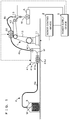
- FIG. 1 is a schematic diagram illustrating a configuration example of an arc welding system according to Embodiment 1.
- An arc welding system according to the present embodiment is a gas shield arc welding machine of a consumable electrode type that includes a welding robot 1, a robot control device 2, a wire feeding source 3, a wire feeding device 4 and a power supply device 5.
- the welding robot 1 automatically performs arc welding of a base material A.
- the welding robot 1 includes a base 11 fixed to an appropriate position on a floor surface. To the base 11, multiple arms 12 are rotatably connected via a shaft (not illustrated). A welding torch 13 is held at the tip end of the arm 12 connected to the distal end side. A motor is provided at the connecting portion of the arms 12, to rotate the arms 12 around the shaft by the rotary drive force of the motor. The rotation of the motor is controlled by the robot control device 2.
- the robot control device 2 may move the welding torch 13 with respect to the base material A in the upper, lower, front, back, left and right directions by rotating the arms 12.
- an encoder is located that outputs a signal indicating a rotated position of each arm 12 to the robot control device 2, which recognizes the position of the welding torch 13 based on the signal output from the encoder.
- the welding torch 13 is made of conductive material such as copper alloy, and has a cylindrical contact chip which guides welding wire W to the base material A to be welded while supplying welding current required to generate arc.
- the contact chip makes contact with welding wire W penetrating into the contact chip, and supplies welding current to the welding wire W.
- the welding torch 13 has a nozzle having a hollow cylindrical shape surrounding the contact chip for spraying shield gas to the base material A through an opening at the tip end.
- the shield gas is to prevent oxidation of the base material A melted by the arc as well as the welding wire W.
- the shield gas is, for example, carbon dioxide gas, mixed gas containing carbon dioxide gas and argon gas, or inert gas such as argon.
- the wire feeding source 3 stores the welding wire W so as to veer out the welding wire W to the welding torch 13.
- the welding wire W is, for example, solid wire having a diameter of 0.8mm to 1.6mm, and functions as a consumable electrode.
- the wire feeding source 3 is a pack wire stored into a pail pack while being wound in a helical manner, or a reel wire wound around a wire reel.
- the wire feeding device 4 is provided with an intermediate wire feeding source 41 that is disposed between the wire feeding source 3 and the welding torch 13 and is configured to temporarily store the welding wire W fed from the wire feeding source 3 and to feed the stored welding wire W to the welding torch 13.
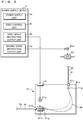
- FIG. 2 is a schematic diagram illustrating a configuration example of an intermediate wire feeding source 41 and a power supply device 5 according to Embodiment 1.
- the intermediate wire feeding source 41 is to absorb the difference in the wire feeding speed between different parts in the feed path, and also to reduce the feeding load of the welding wire W on the welding torch 13 side.
- the intermediate wire feeding source 41 has a hollow substantially-rectangular-parallelepiped housing 41a that stores the welding wire W.
- An inlet part 41b through which the welding wire W fed from the wire feeding source 3 is formed on a side surface of the housing 41a, and an outlet part 41c through which the welding wire W stored inside the housing 41a is sent out are formed on an upper surface of the housing 41a.
- the welding wire W pulled into the housing 41a is stored in a state of being bent in an arc between the inlet part 41b and the outlet part 41c.
- the wire feeding source 3 and the inlet part 41b of the intermediate wire feeding source 41 are connected via the first conduit cable 4a through which the welding wire W passes.
- a first feeding part 41d that pulls out the welding wire W from the wire feeding source 3 and pushes the welding wire W into the housing 41a through the inlet part 41b is provided.
- the first feeding part 41d has a pair of rollers that are opposed to each other at positions where the rollers can hold the welding wire W introduced through the inlet part 41b between them. At least one of the rollers is rotary driven by a first motor 41e which is capable of controlling the speed.
- the first feeding part 41d may feed the welding wire W at a speed of 30-100 meters per minute, for example.
- the intermediate wire feeding source 41 is provided with an input port 41f through which a speed instruction signal output from the power supply device 5 is input, and the first motor 41e rotates a roller at a speed according to the speed instruction signal input to the input port 41f.
- the first motor 41e detects the rotation speed of the roller by an encoder (not illustrated), for example, and operates so as to rotate the roller at a rotation speed according to the speed instruction signal.
- the welding wire W pulled into the housing 41a from the first conduit cable 4a through the inlet part 41b is curved into an arbitrary shape, and a predetermined amount of welding wire W is stored into the housing 41a.
- the welding wire W is stored while being curved into an arc.
- a member for guiding the welding wire W may be provided inside the housing 41a so that the welding wire W is stored in a predetermined spatial area without being entangled.
- a guide roller 41g for example, is located at each of the inlet part 41b and the outlet part 41c inside the housing 41a.
- the guide roller 41g on the inlet part 41b side is disposed at the outlet side of the first feeding part 41d and has a pair of rollers that are opposed to each other at positions where the rollers can hold the welding wire W between them and guide it from the inlet part 41b into the housing 41a.
- the guide roller 41g on the outlet part 41c side has a pair of rollers opposed to each other at positions where the rollers can hold the welding wire W between them and guide it from an inside of the housing 41a to the outlet part 41c.
- the guide roller 41g may be configured to be rotary driven by a motor which rotates in synchronization with the first motor 41e, or be passively rotated.
- the wire feeding device 4 is provided with a second feeding part 42 that pulls out the welding wire W from the intermediate wire feeding source 41 and feeds the pulled-out welding wire W to the welding torch 13.
- the second feeding part 42 is located, for example, at the arm 12 of the welding robot 1, as illustrated in FIG. 1 .
- the second feeding part 42 is connected to the outlet part 41c of the intermediate wire feeding source 41 by a second conduit cable 4b through which the welding wire W passes, and is connected to the welding torch 13 by a third conduit cable 4c.
- the intermediate wire feeding source 41 is aligned with and in the vicinity of the welding robot 1.
- the second feeding part 42 has a pair of rollers that are opposed to each other at positions where the welding wire W may be held between them, and the rollers are rotated so as to pull out the welding wire W from the intermediate wire feeding source 41 and feeds the pulled-out welding wire W to the welding torch 13. At least one of the rollers is rotary driven by a second motor 42a which is capable of controlling the speed.
- the second feeding part 42 may feed the welding wire W at a speed of 30-100 meters per minute, for example.
- the second feeding part 42 rotates the rollers based on a speed instruction signal output from the power supply device 5.
- the second motor 42a detects the rotation speed of the roller by an encoder (not illustrated), for example, and operates so as to rotate the roller at a rotation speed according to the speed instruction signal.
- the power supply device 5 is connected to the contact chip of the welding torch 13 and the base material A via the power supply cable, and includes a power supply unit 5a that supplies welding current, a feed control unit 5b that controls the feeding speed of the welding wire W, a first speed instruction output unit 5c and a second speed instruction output unit 5d that output speed instruction signals respectively to the first feeding part 41d and the second feeding part 42.
- the power supply unit 5a is an insulating switching power supply, which performs AC/DC conversion on the alternating current into required direct current, and supplies the converted direct current to the load. More specifically, the power supply unit 5a includes a power supply circuit that outputs PWM-controlled direct current, a signal processing unit that controls the operation of the power supply circuit, a voltage detection unit, a current detection unit, and so forth.
- the voltage detection unit detects voltage applied to the welding torch 13 and the base material A, and outputs a voltage value signal indicating the detected voltage value to the signal processing unit.
- the current detection unit detects, for example, welding current supplied from the power supply device 5 to the welding wire W via the welding torch 13 and flows through the arc, and outputs a current value signal indicating the detected current value to the signal processing unit.
- the signal processing unit outputs a signal for PWM-controlling the power supply circuit to the power supply circuit, based on a voltage value signal, a current value signal, a set value for the welding condition and the like.
- the power supply circuit includes, for example, an AC-DC converter performing AC-DC conversion on commercial alternate current, an inverter circuit converting direct current subjected to AC-DC conversion into required alternate current by switching, and a rectification circuit rectifying the alternate current obtained by conversion.
- the power supply circuit performs PWM control on the inverter circuit in accordance with the signal output from the signal processing unit, and outputs predetermined welding current and voltage to the welding wire W. For example, welding voltage that varies periodically is applied between the base material A and the welding wire W, and the welding current flows.
- the power supply device 5 is configured to receive an output instruction signal from the robot control device 2 via a control communication line. The power supply unit 5a starts supplying welding current to the power supply circuit using the output instruction signal as a trigger.
- the feed control unit 5b causes the first speed instruction output unit 5c and the second speed instruction output unit 5d to output speed instruction signals indicating the feeding speed according to welding conditions to the first feeding part 41d and the second feeding part 42, respectively.
- the speed instruction signal output to the first feeding part 41d is substantially equal to the speed instruction signal output to the second feeding part 42, and the first feeding part 41d and the second feeding part 42 feed the welding wire W at substantially the same speed.
- the speed instruction signals to be output to the first feeding part 41d and the second feeding part 42 are not necessarily identical to each other, since a difference exists in the diameters of the rollers constituting the first feeding part 41d and the second feeding part 42.
- Substantially equal speed instruction signals include signals that are different from each other within such a range that no problem of slipping, buckling or the like of the welding wire W occurs and that the welding wire W of a predetermined amount is stored in the intermediate wire feeding source 41.
- the feed control unit 5b of the power supply device 5 outputs substantially equal speed instruction signals according to welding conditions to the first feeding part 41d and the second feeding part 42, to control the speed of feeding the welding wire W by the first feeding part 41d and the second feeding part 42.
- the first feeding part 41d and the second feeding part 42 rotate the rollers in accordance with speed control signals output from the power supply device 5, and feed the welding wire W at a required speed.
- the welding wire W is stored into the intermediate wire feeding source 41 in a state of being bent in an arc between the inlet part 41b and the outlet part 41c. Therefore, compared to the case where the welding wire W is largely bent such as in a loop to be stored into the housing 41a, the feeding load may be reduced. Also, compared to the case where the welding wire W is stored in a loop, the internal structure of the housing 41a may be simplified.
- the difference in the feeding speed may be suppressed to the minimum, and thus the housing 41a may be reduced in size.
- the welding wire W may stably be fed from the intermediate wire feeding source 41 to the welding torch 13.
- the welding wire W may stably be fed to the welding torch 13.
- Embodiment 1 described the example where the first feeding part 41d is located inside the housing 41a of the intermediate wire feeding source 41, the first feeding part 41d and the intermediate wire feeding source 41 may be formed as separate units.
- the position of the separate first feeding part 41d is not necessarily limited, and may be at the wire feeding source 3.
- the position of the intermediate wire feeding source 41 is not particularly limited but may alternatively be at the arm 12 of the welding robot 1.
- Embodiment 2 As an arc welding device and a wire feeding device 204 according to Embodiment 2 are different from those in Embodiment 1 in the details of the intermediate wire feeding source 241 and the feed control method, the difference will mainly be described below. Since the other configurations and effects are similar to those in Embodiment 1, corresponding parts are denoted by similar reference codes and detailed description thereof will not be repeated.
- FIG. 3 is a schematic diagram illustrating a configuration example of an intermediate wire feeding source 241 and a power supply device 205 according to Embodiment 2.
- the intermediate wire feeding source 241 according to Embodiment 2 includes a housing 41a which is similar to that in Embodiment 1, and is provided with an inlet part 41b, an outlet part 41c, a first feeding part 41d, a first motor 41e, an input port 41f and a guide roller 41g.
- the intermediate wire feeding source 241 is provided with an stored amount detection unit 241h that detects the stored amount of welding wire W.
- the stored amount detection unit 241h is provided with a bar member 241i with one end rotatably fixed thereto. At the other end of the bar member 241i, a pair of curvature detection rollers 241j that pinch the bent portion of the welding wire W are rotatably supported. If the stored amount of the welding wire W is increased or decreased, the curvature of the welding wire W stored inside the housing 41a changes as illustrated by the two-dot chain lines in FIG. 3 , and the bar member 241i pivots around the one end described above.
- the stored amount detection unit 241h is a rotary position sensor that detects the rotary position of the bar member 241i, and by detecting the rotary position of the bar member 241i, the stored amount detection unit 241h can detect the stored amount of welding wire W, and outputs a detection signal indicating the stored amount to the power supply device 205 via the output port 241k.
- the stored amount detection unit 241h provided with the rotary position sensor is a mere example, and the stored amount of welding wire W may be optically detected with the use of an infrared sensor or the like. Moreover, a limit switch which is in contact with the stored welding wire W and is turned on or off in accordance with the stored amount of the welding wire W may also be used to configure the stored amount detection unit 241h.
- the power supply device 205 is provided with a power supply unit 5a, a feed control unit 5b, a first speed instruction output unit 5c, a second speed instruction output unit 5d, and is further provided with a signal input unit 205e to which a detection signal output from the intermediate wire feeding source 241 is input.
- the power supply device 205 corrects the feeding speed indicated by a speed instruction for the first feeding part 41d based on the detection signal input to the signal input unit 205e, and outputs the corrected speed instruction signal to the first feeding part 41d.
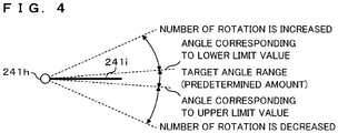
- FIG. 4 is a schematic view illustrating a method of correcting feeding speed
- FIG. 5 is a graph illustrating the relationship between the rotation angle of the bar member 241i detected by the stored amount detection unit 241h and a correction amount for feeding speed.
- the horizontal axis indicates the rotation angle of the bar member 241i
- the vertical axis indicates the correction amount of speed instructions.
- the rotation angle of the bar member 241i is increased or decreased according to the stored amount of welding wire W in the intermediate wire feeding source 241.
- the rotation angle of the bar member 241i is smaller when the stored amount of welding wire W is increased (clockwise rotation in FIGS. 3 and 4 ), and is larger when the stored amount of welding wire W is decreased (counterclockwise rotation in FIGS. 3 and 4 ).
- a predetermined amount of welding wire W is stored in the intermediate wire feeding source 241.
- the predetermined amount corresponds to the amount of welding wire W to be stored in the intermediate wire feeding source 241, and has a lower limit and an upper limit. That is, the predetermined amount has a certain width.
- the target angle range illustrated in FIG. 4 is a rotation angle of the bar member 241i corresponding to the predetermined amount.
- the rotation angle of the bar member 241i corresponding to the upper limit is -5 degrees, for example, and the rotation angle of the bar member 241i corresponding to the lower limit is 5 degrees.
- the feed control unit 5b increases the speed of feeding by the first feeding part 41d if the stored amount of welding wire W is smaller than the lower limit, e.g., if the rotation angle of the bar member 241i is 5 degrees or larger. That is, the number of rotation by the roller of the first feeding part 41d is increased. More specifically, the feed control unit 5b calculates a correction amount (%) proportional to the difference between the rotation angle of the bar member 241i detected by the store amount detection unit 241h and an angle corresponding to the lower limit. The feed control unit 5b then corrects the feeding speed of the first feeding part 41d by adding a value obtained by multiplying the feeding speed before correction, i.e. the feeding speed of the second feeding part 42, by the correction amount (%) to the feeding speed. The feed control unit 5b outputs a speed instruction signal indicating the feeding speed after correction to the first feeding part 41d.
- the feed control unit 5b decreases the feeding speed of the first feeding part 41d if the stored amount of welding wire W is larger than the upper limit, e.g., if the rotation angle of the bar member 241i is -5 degrees or smaller. That is, the number of rotation by the roller of the first feeding part 41d is decreased. More specifically, the feed control unit 5b calculates a correction amount (%) proportional to the difference between the rotation angle of the bar member 241i detected by the store amount detection unit 241h and an angle corresponding to the lower limit. The feed control unit 5b then corrects the feeding speed of the first feeding part 41d by multiplying the feeding speed before correction, i.e. the feeding speed of the second feeding part 42, by a negative correction amount (%), and adding the value obtained by the multiplication to the feeding speed. The feed control unit 5b outputs a speed instruction signal indicating the feeding speed after correction to the first feeding part 41d.
- the feed control unit 5b If the stored amount of welding wire W is in the range from the lower limit to the upper limit, i.e. if the rotation angle of bar member 241i is within the target angle range, the feed control unit 5b does not correct the feeding speed according to the rotation angle. In other words, the feed control unit 5b performs no deviation control based on the difference between the rotation angle of the bar member 241i and a target angle, e.g., 0 degrees.
- FIG. 6 is a graph illustrating the relationship between a change rate of the rotation angle of a bar member 241i detected by the stored amount detection unit 241h and a correction amount for feeding speed.
- the horizontal axis indicates the change rate of the rotation angle of the bar member 241i
- the vertical axis indicates the correction amount of speed instructions. If the stored amount of welding wire W in the intermediate wire feeding source 241 is in the range of a predetermined amount, the feed control unit 5b corrects the feeding speed of welding wire W fed by the first feeding part 41d in accordance with the change rate of the stored amount. More specifically, the correction amount proportional to the change rate of the rotation angle of the bar member 241i is calculated.
- the feed control unit 5b then corrects the feeding speed of the first feeding part 41d by adding a value obtained by multiplying the feeding speed before correction, i.e. the feeding speed of the first feeding part 41d, by the correction amount (%) to the feeding speed.
- the feed control unit 5b outputs a speed instruction signal indicating the feeding speed after correction to the first feeding part 41d.
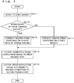
- FIG. 7 is a flowchart illustrating a processing procedure performed by the feed control unit 5b according to Embodiment 2.
- the feed control unit 5b causes the stored amount detection unit 241h to detect the stored amount of welding wire W (step S211), and determines whether or not the stored amount is within the range of a predetermined amount (step S212). If it is determined that the stored amount is in the range of a predetermined amount (YES at step S212), the feed control unit 5b corrects the feeding speed according to welding conditions depending on the change rate of the stored amount as illustrated in FIG. 6 (step S213).
- the feed control unit 5b corrects the feeding speed according to welding conditions depending on the difference between the upper limit or lower limit of the predetermined amount and the stored amount, as illustrated in FIG. 5 (step S214).
- the feed control unit 5b that has finished the processing of step S213 or S214 outputs a speed instruction signal indicating the corrected feeding speed to the first feeding part 41d via the first speed instruction output unit 5c (step S215).
- the feed control unit 5b outputs a speed instruction signal indicating the feeding speed according to the welding conditions to the second feeding part 42 via the second speed instruction output unit 5d (step S216).
- the feed control unit 5b proportionally controls the feeding speed of welding wire W fed by the first feeding part 41d, and if it is within the range of the predetermined amount, differential control may be performed on the feeding speed of welding wire W fed by the first feeding part 41d.
- the storage amount of welding wire W stored in the housing 41a is monitored so that a predetermined amount of welding wire W is stored in the intermediate wire feeding source 241, which enables stable feeding of the welding wire W from the intermediate wire feeding source 241 to the welding torch 13.
- the stored amount of welding wire W in the intermediate wire feeding source 241 is out of the predetermined range, proportional control is performed on the feeding speed of welding wire W fed by the first feeding part 41d. That is, if the stored amount of welding wire W is larger than the upper limit, the stored amount is reduced by correcting the feeding speed of the first feeding part 41d to be lower. If, on the other hand, the stored amount of welding wire W is smaller than the lower limit, the stored amount is increased by correcting the feeding speed of the first feeding part 41d to be higher.
- the predetermined amount of welding wire W is secured in the intermediate wire feeding source 241, and the welding wire W may stably be fed to the welding torch 13.
- some latitude is allowed as to the predetermined amount to be stored in the intermediate wire feeding source 241, which can prevent the feeding speed of welding wire W fed by the first feeding part 41d from unnecessarily varying. In other words, the storage state of the welding wire W in the intermediate wire feeding source 241 may be stabilized.
- the stored amount of welding wire W in the intermediate wire feeding source 241 is in the predetermined range, differential control is performed on the feeding speed of welding wire W fed by the first feeding part 41d.
- the speed of feeding by the first feeding part 41d is controlled so that the stored amount is not changed from the current value, which can stabilize the storage state of the welding wire W in the intermediate wire feeding source 241.
- Embodiment 3 As the arc welding device and the wire feeding device 304 according to Embodiment 3 are different from those in Embodiment 2 in the configuration of the power supply device 305, the difference will mainly be described below. Since the other configurations and effects are similar to those in Embodiments 1 and 2, corresponding parts are denoted by similar reference codes and detailed description thereof will not be repeated.
- FIG. 8 is a schematic diagram illustrating a configuration example of an arc welding system according to Embodiment 3.
- the power supply device 305 according to Embodiment 3 includes a first power supply 351 and a second power supply 352 that are connected in parallel to a common load concerning arc welding, to feed electricity to the load, and is able to output large current.
- the first power supply 351 and the second power supply 352 are connected with each other by a communication line.
- the second power supply 352 transmits PWM control information to the first power supply 351 through a communication line, to function as a master power supply that controls the outputs of the first and second power supplies 351 and 352.
- the first power supply 351 receives the PWM control information transmitted from the second power supply 352, and functions as a slave power supply that controls the output based on the received PWM control information.
- the second power supply 352 includes a second power supply unit 352a, a second control unit 352b, a second speed instruction output unit 352c, a second signal input/output unit 352d, and a second communication unit 352e.
- the second power supply unit 352a, the second control unit 352b and the second speed instruction output unit 352c are configured similarly to those in the power supply device 5 described in Embodiment 2.
- the second control unit 352b causes the second speed instruction output unit 352c to output speed instruction signals to the second feeding part 42, to control the speed of feeding the welding wire W by the second feeding part 42.
- the second signal input/output unit 352d is a terminal connected to an external device, and receives input/output of signals. To the terminal, an operation device for operating an arc welding device is connected, for example.
- the second communication unit 352e is a communication circuit for transmitting and receiving various information to/from the first power supply 351.
- the second communication unit 352e transmits and receives information according to the host control interface (HCI) communication protocol, for example.
- HCI host control interface
- the second power supply 352 which employs a master power mode as the operation mode transmits through the second communication unit 352e the speed information of the second feeding part 42 and the PWM control information calculated at the second power supply unit 352a of its own device to the first power supply 351 operating in the slave mode.
- the first power supply 351 is configured similarly to the second power supply 352, and includes a first power supply unit 351a, a first control unit 351b, a first speed instruction output unit 351c, a first signal input/output unit 351d and a first communication unit 351e.
- the first power supply 351 receives, by the first communication unit 351e, the speed information and PWM control information transmitted from the second power supply 352 operating in the master power mode.
- the first power supply unit 351a outputs welding current based on the received PWM control information.
- An stored amount detection unit 241h is connected to the first signal input/output unit 351d, and a signal indicating the result of detection performed by the stored amount detection unit 241h is input to the first signal input/output unit 351d.
- the first signal input/output unit 351d is configured similarly to the second signal input/output unit 352d.
- an external device e.g., an operation device for operating the arc welding device, may be connected to the first signal input/output unit 351d.
- the first control unit 351b corrects the speed information received at the first communication unit 351e based on the signals input to the first signal input/output unit 351d, and outputs speed instruction signals indicating the corrected speed information from the first speed instruction output unit 351c to the first feeding part 41d.
- the method of correcting the feeding speed of the first feeding part 41d is as described in Embodiment 2, and the first control unit 351b causes the first speed instruction output unit 351c to output speed instruction signals to the first feeding part 41d, to control the speed of feeding the welding wire W by the first feeding part 41d.
- FIG. 9 is a flowchart illustrating a processing procedure for the first control unit 351b and the second control unit 352b according to Embodiment 3.
- the second control unit 352b of the second power supply 352 outputs speed instruction signals indicating the feeding speed in accordance with the welding conditions to the second feeding part 42 through the second speed instruction output unit 352c, to control the speed of feeding by the second feeding part 42 (step S311).
- the second control unit 352b transmits the speed information indicating the feeding speed of the second feeding part 42 to the first power supply 351 through the second communication unit 352e (step S312).
- the first control unit 351b of the first power supply 351 receives, by the first communication unit 351e, the speed information transmitted from the second power supply 352 (step S313). Subsequently, the first control unit 351b causes the stored amount detection unit 241h to detect the stored amount of welding wire W (step S314), and determines whether or not the stored amount is within the range of the predetermined amount (step S315). If it is determined that the stored amount is in the range of the predetermined amount (YES at step S315), the first control unit 351b corrects the feeding speed indicated by the received speed information in accordance with the change rate of the stored amount as illustrated in FIG. 6 (step S316).
- the first control unit 351b corrects the feeding speed indicated by the received speed information in accordance with the difference between the stored amount and the upper limit or lower limit of the predetermined amount, as illustrated in FIG. 5 (step S317).
- the first control unit 351b that has finished the processing of step S316 or S317 outputs speed instruction signals indicating the corrected feeding speed to the first feeding part 41d via the first speed instruction output unit 351c (step S318).
- the wire feeding device 304 and arc welding device according to Embodiment 3 configured as described above, even in the configuration where each of the first power supply 351 and the second power supply 352 is provided with only one port for outputting a speed instruction to the first feeding part 41d or the second feeding part 42, i.e. the first speed instruction output unit 351c or the second speed instruction output unit 352c, the feeding speed of welding wire W by both the first feeding part 41d and the second feeding part 42 may be controlled.
- Embodiment 3 described the configuration where the first power supply 351 and the second power supply 352 respectively control the speed for the first feeding part 41d and the second feeding part 42
- three or more power supplies may be connected in parallel.
- additional sets of intermediate wire feeding sources and the first feeding parts may be provided, and multiple power supplies may control the speed of feeding the welding wire W by multiple first feeding parts and second feeding parts.
- Embodiment 3 described the configuration where the first power supply 351 serving as a slave power supply controls the feeding by the first feeding part 41d and the configuration where the second power supply 352 serving as a master power supply controls the feeding by the second feeding part 42, it is, to the contrary, also possible for the second power supply 352 of the master power supply to control the feeding of the first feeding part 41d, and for the first power supply 351 of the slave power supply to control the feeding of the second feeding part 42.
- Embodiment 4 As an arc welding device and a wire feeding device 404 according to Embodiment 4 are different from those in Embodiment 1 in that the wire feeding source 3 is further provided with a third feeding part 443, the difference will mainly be described below. Since the other configurations and effects are similar to those in Embodiment 1, corresponding parts are denoted by similar reference codes and detailed description thereof will not be repeated.
- FIG. 10 is a schematic diagram illustrating a configuration example of an arc welding system according to Embodiment 4.
- the wire feeding device 404 according to Embodiment 4 is provided with a third feeding part 443 that pulls out the welding wire W from the wire feeding source 3 and pushes it out to the intermediate wire feeding source 41.
- the third feeding part 443 is provided with, for example, a roller on which torque control is performed, and the feeding of welding wire W fed by the third feeding part 443 is controlled by the power supply device 5.
- the third feeding part 443 allows for stable feeding of welding wire W to the welding torch 13.
Landscapes
- Engineering & Computer Science (AREA)
- Physics & Mathematics (AREA)
- Plasma & Fusion (AREA)
- Mechanical Engineering (AREA)
- Arc Welding Control (AREA)
- Arc Welding In General (AREA)
Abstract
Description
- The present invention relates to a wire feeding device that feeds welding wire to a welding torch, and an arc welding device.
- An arc welding system of a consumable electrode type is provided with: a wire feeding device that feeds welding wire from a wire feeding source to a welding torch; and a power supply device. The wire feeding device of a push-pull type is provided with a push feeder that pushes out welding wire from a wire feeding source such as a wire reel, pack wire or the like to a welding torch, and a pull feeder that is located at an arm or the like of a welding robot and that pulls in the welding wire pushed out by the push feeder to feed it to the welding torch. Generally, the push feeder is torque-controlled, whereas the pull feeder is speed-controlled (Patent Document 1, for example).
- [Patent Document 1] Japanese Patent Application Laid-Open Publication No.
2006-907 - In Japanese Patent Application Laid-Open Publication No.
2006-907 - The present invention has been made in view of the circumstances described above, and aims to provide a wire feeding device and an arc welding device capable of stably feeding welding wire to a welding torch at a required speed.
- A wire feeding device according to an aspect of the present invention configured to feed welding wire from a wire feeding source to a welding torch is provided with: an intermediate wire feeding source that is disposed between the wire feeding source and the welding torch and is configured to temporarily store the welding wire fed from the wire feeding source and to feed the stored welding wire to the welding torch; a first feeding part that feeds the welding wire at the wire feeding source to the intermediate wire feeding source; a second feeding part that feeds the welding wire stored in the intermediate wire feeding source to the welding torch; and a feed control unit that controls speed of feeding the welding wire by each of the first feeding part and the second feeding part.
- According to an aspect of the present invention, since speed control is performed for wire feeding by both the first feeding part and the second feeding part, basically no problem of delay in following is caused in the feeding speed of the first feeding part with respect to the second feeding speed, thereby achieving high response to wire feeding. Since the intermediate wire feeding source is provided between the first feeding part and the second feeding part, it is not necessary to highly precisely synchronize the first feeding part with the second feeding part, and the welding wire may stably be fed to the welding torch at a required speed. Furthermore, the wire feeding device according to an aspect of the present invention requires no torque adjustment which is required in torque control.
- In the wire feeding device according to an aspect of the present invention, the feed control unit controls the speed of feeding by each of the first feeding part and the second feeding part so that the feeding speed of welding wire is substantially equal to each other.
- According to an aspect of the present invention, as the feeding speed of welding wire fed by the first feeding part and the second feeding part is substantially equal to each other, the welding wire may stably be fed to the welding torch at the feeding speed.
- The wire feeding device according to an aspect of the present invention includes a detection unit that detects the stored amount of welding wire stored in the intermediate wire feeding source, and the feed control unit corrects the feeding speed of welding wire fed by the first feeding part so that a predetermined amount of welding wire is stored in the intermediate wire feeding source based on the detection result obtained by the detection unit.
- According to an aspect of the present invention, the feeding speed of welding wire fed by the first feeding part is corrected so that a predetermined amount of welding wire is stored in the intermediate wire feeding source. Even if a difference is generated in the feeding speed of welding wire between the first feeding part and the second feeding part, the predetermined amount of welding wire is secured in the intermediate
wire feeding source 41, and the welding wire may stably be fed to the welding torch. - In the wire feeding device according to an aspect of the present invention, the predetermined amount has an upper limit and a lower limit, and if the stored amount detected by the detection unit is larger than the upper limit, the feed control unit corrects the feeding speed of welding wire fed by the first feeding part so as to decrease the feeding speed in accordance with a difference between the stored amount and the upper limit, whereas if the stored amount detected by the detection unit is smaller than the lower limit, the feeding speed of wire fed by the first feeding part is corrected so as to increase the feeding speed in accordance with the difference between the stored amount and the lower limit.
- According to an aspect of the present invention, the welding wire of an amount in a range from a predetermined lower limit to an upper limit is secured in the intermediate wire feeding source. If the stored amount of welding wire is larger than the upper limit, the feeding speed of the first feeding part is decreased so as to reduce the stored amount. If, on the other hand, the stored amount of welding wire is smaller than the lower limit, the feeding speed of the first feeding part is increased so as to increase the stored amount.
- In the wire feeding device according to an aspect of the present invention, the feed control unit corrects the feeding speed of welding wire fed by the first feeding part so as to decrease the feeding speed if the change rate of the stored amount is a positive value in the case where the stored amount detected by the detection unit is in a range from the lower limit to the upper limit, and corrects the feeding speed of welding wire fed by the first feeding part so as to increase the feeding speed if the change rate of the stored amount is a negative value.
- According to an aspect of the present invention, in the case where the welding wire of an amount in a range from a predetermined lower limit to an upper limit is in the intermediate wire feeding source, the stored amount of welding wire is stabilized at the current stored amount. This may prevent variation in the amount of welding wire stored in the intermediate wire feeding source, which thus can stabilize the stored state of welding wire in the intermediate wire feeding source, and can stably supply the welding wire to the welding torch.
- The arc welding device according to an aspect of the present invention comprises: the wire feeding device as described above; and a power supply device that supplies welding current to the welding wire to be fed to a base material by the wire feeding device, and generates arc between a tip end of the welding wire and a portion to be welded, to weld the base material.
- According to an aspect of the present invention, welding wire may stably be fed to a welding torch at a required speed to perform arc welding for the base material.
- In the arc welding device according to an aspect of the present invention, the power supply device includes the first power supply and the second power supply that are connected in parallel, the feed control unit includes a first control unit that is located at the first power supply and that controls the speed of feeding by the first feeding part, and a second control unit that is located at the second power supply and that controls the speed of feeding by the second feeding part. The second power supply includes a transmission unit that transmits speed information indicating the feeding speed of welding wire fed by the second feeding part to the first power supply, the first power supply includes a reception unit that receives speed information transmitted from the second power supply, and the first control unit controls the speed of feeding by the first feeding part based on the speed information received by the reception unit.
- According an aspect of the present invention, the power supply device includes at least two power supplies that are connected in parallel, that is, the first power supply and the second power supply. The first control unit located at the first power supply controls the speed for the first feeding part, whereas the second control unit located at the second power supply controls the speed for the second feeding part. The second power supply transmits speed information indicating the feeding speed of welding wire fed by the second feeding part to the first power supply, and the first power supply receives speed information transmitted from the second power supply. The first control unit controls the speed of feeding by the first feeding part based on the speed information. Accordingly, even in the configuration where each of the power supplies is provided with only one port for outputting a command for speed to the feeding parts, the feeding speed of welding wire by both the first feeding part and the second feeding part may be controlled.
- According to an aspect of the present invention, welding wire may stably be fed to a welding torch at a required speed.
-
-
FIG. 1 is a schematic diagram illustrating a configuration example of an arc welding system according to Embodiment 1; -
FIG. 2 is a schematic diagram illustrating a configuration example of an intermediate wire feeding source and a power supply device according to Embodiment 1; -
FIG. 3 is a schematic diagram illustrating a configuration example of an intermediate wire feeding source and a power supply device according toEmbodiment 2; -
FIG. 4 is a schematic diagram illustrating a correction method for feeding speed; -
FIG. 5 is a graph illustrating the relationship between a rotation angle of a bar member detected by the stored amount detection unit and a correction amount for feeding speed; -
FIG. 6 is a graph illustrating the relationship between a change rate of the rotation angle of a bar member detected by the stored amount detection unit and a correction amount for feeding speed; -
FIG. 7 is a flowchart illustrating a processing procedure performed by a feed control unit according toEmbodiment 2; -
FIG. 8 is a schematic diagram illustrating a configuration example of an arc welding system according toEmbodiment 3; -
FIG. 9 is a flowchart illustrating a processing procedure for the first control unit and the second control unit according toEmbodiment 3; and -
FIG. 10 is a schematic diagram illustrating a configuration example of an arc welding system according toEmbodiment 4. - The present invention will be described below in detail with reference to the drawings illustrating the embodiments thereof. At least some parts of the embodiments described below may arbitrarily be combined together.
-
FIG. 1 is a schematic diagram illustrating a configuration example of an arc welding system according to Embodiment 1. An arc welding system according to the present embodiment is a gas shield arc welding machine of a consumable electrode type that includes a welding robot 1, arobot control device 2, awire feeding source 3, awire feeding device 4 and apower supply device 5. - The welding robot 1 automatically performs arc welding of a base material A. The welding robot 1 includes a
base 11 fixed to an appropriate position on a floor surface. To thebase 11,multiple arms 12 are rotatably connected via a shaft (not illustrated). Awelding torch 13 is held at the tip end of thearm 12 connected to the distal end side. A motor is provided at the connecting portion of thearms 12, to rotate thearms 12 around the shaft by the rotary drive force of the motor. The rotation of the motor is controlled by therobot control device 2. Therobot control device 2 may move thewelding torch 13 with respect to the base material A in the upper, lower, front, back, left and right directions by rotating thearms 12. Moreover, at the connecting portion of thearms 12, an encoder is located that outputs a signal indicating a rotated position of eacharm 12 to therobot control device 2, which recognizes the position of thewelding torch 13 based on the signal output from the encoder. - The
welding torch 13 is made of conductive material such as copper alloy, and has a cylindrical contact chip which guides welding wire W to the base material A to be welded while supplying welding current required to generate arc. The contact chip makes contact with welding wire W penetrating into the contact chip, and supplies welding current to the welding wire W. Moreover, thewelding torch 13 has a nozzle having a hollow cylindrical shape surrounding the contact chip for spraying shield gas to the base material A through an opening at the tip end. The shield gas is to prevent oxidation of the base material A melted by the arc as well as the welding wire W. The shield gas is, for example, carbon dioxide gas, mixed gas containing carbon dioxide gas and argon gas, or inert gas such as argon. - The
wire feeding source 3 stores the welding wire W so as to veer out the welding wire W to thewelding torch 13. The welding wire W is, for example, solid wire having a diameter of 0.8mm to 1.6mm, and functions as a consumable electrode. Thewire feeding source 3 is a pack wire stored into a pail pack while being wound in a helical manner, or a reel wire wound around a wire reel. - The
wire feeding device 4 is provided with an intermediatewire feeding source 41 that is disposed between thewire feeding source 3 and thewelding torch 13 and is configured to temporarily store the welding wire W fed from thewire feeding source 3 and to feed the stored welding wire W to thewelding torch 13. -
FIG. 2 is a schematic diagram illustrating a configuration example of an intermediatewire feeding source 41 and apower supply device 5 according to Embodiment 1. The intermediatewire feeding source 41 is to absorb the difference in the wire feeding speed between different parts in the feed path, and also to reduce the feeding load of the welding wire W on thewelding torch 13 side. The intermediatewire feeding source 41 has a hollow substantially-rectangular-parallelepiped housing 41a that stores the welding wire W.An inlet part 41b through which the welding wire W fed from thewire feeding source 3 is formed on a side surface of thehousing 41a, and anoutlet part 41c through which the welding wire W stored inside thehousing 41a is sent out are formed on an upper surface of thehousing 41a. The welding wire W pulled into thehousing 41a is stored in a state of being bent in an arc between theinlet part 41b and theoutlet part 41c. - The
wire feeding source 3 and theinlet part 41b of the intermediatewire feeding source 41 are connected via thefirst conduit cable 4a through which the welding wire W passes. At theinlet part 41b inside thehousing 41a, afirst feeding part 41d that pulls out the welding wire W from thewire feeding source 3 and pushes the welding wire W into thehousing 41a through theinlet part 41b is provided. Thefirst feeding part 41d has a pair of rollers that are opposed to each other at positions where the rollers can hold the welding wire W introduced through theinlet part 41b between them. At least one of the rollers is rotary driven by afirst motor 41e which is capable of controlling the speed. - The
first feeding part 41d may feed the welding wire W at a speed of 30-100 meters per minute, for example. The intermediatewire feeding source 41 is provided with aninput port 41f through which a speed instruction signal output from thepower supply device 5 is input, and thefirst motor 41e rotates a roller at a speed according to the speed instruction signal input to theinput port 41f. Thefirst motor 41e detects the rotation speed of the roller by an encoder (not illustrated), for example, and operates so as to rotate the roller at a rotation speed according to the speed instruction signal. - The welding wire W pulled into the
housing 41a from thefirst conduit cable 4a through theinlet part 41b is curved into an arbitrary shape, and a predetermined amount of welding wire W is stored into thehousing 41a. In the example illustrated inFIG. 2 , the welding wire W is stored while being curved into an arc. A member for guiding the welding wire W may be provided inside thehousing 41a so that the welding wire W is stored in a predetermined spatial area without being entangled. Aguide roller 41g, for example, is located at each of theinlet part 41b and theoutlet part 41c inside thehousing 41a. More specifically, theguide roller 41g on theinlet part 41b side is disposed at the outlet side of thefirst feeding part 41d and has a pair of rollers that are opposed to each other at positions where the rollers can hold the welding wire W between them and guide it from theinlet part 41b into thehousing 41a. Theguide roller 41g on theoutlet part 41c side has a pair of rollers opposed to each other at positions where the rollers can hold the welding wire W between them and guide it from an inside of thehousing 41a to theoutlet part 41c. It is noted that theguide roller 41g may be configured to be rotary driven by a motor which rotates in synchronization with thefirst motor 41e, or be passively rotated. - Moreover, the
wire feeding device 4 is provided with asecond feeding part 42 that pulls out the welding wire W from the intermediatewire feeding source 41 and feeds the pulled-out welding wire W to thewelding torch 13. Thesecond feeding part 42 is located, for example, at thearm 12 of the welding robot 1, as illustrated inFIG. 1 . Thesecond feeding part 42 is connected to theoutlet part 41c of the intermediatewire feeding source 41 by asecond conduit cable 4b through which the welding wire W passes, and is connected to thewelding torch 13 by athird conduit cable 4c. The intermediatewire feeding source 41 is aligned with and in the vicinity of the welding robot 1. Thesecond feeding part 42 has a pair of rollers that are opposed to each other at positions where the welding wire W may be held between them, and the rollers are rotated so as to pull out the welding wire W from the intermediatewire feeding source 41 and feeds the pulled-out welding wire W to thewelding torch 13. At least one of the rollers is rotary driven by asecond motor 42a which is capable of controlling the speed. Thesecond feeding part 42 may feed the welding wire W at a speed of 30-100 meters per minute, for example. Thesecond feeding part 42 rotates the rollers based on a speed instruction signal output from thepower supply device 5. Thesecond motor 42a detects the rotation speed of the roller by an encoder (not illustrated), for example, and operates so as to rotate the roller at a rotation speed according to the speed instruction signal. - The
power supply device 5 is connected to the contact chip of thewelding torch 13 and the base material A via the power supply cable, and includes apower supply unit 5a that supplies welding current, afeed control unit 5b that controls the feeding speed of the welding wire W, a first speedinstruction output unit 5c and a second speedinstruction output unit 5d that output speed instruction signals respectively to thefirst feeding part 41d and thesecond feeding part 42. - The
power supply unit 5a is an insulating switching power supply, which performs AC/DC conversion on the alternating current into required direct current, and supplies the converted direct current to the load. More specifically, thepower supply unit 5a includes a power supply circuit that outputs PWM-controlled direct current, a signal processing unit that controls the operation of the power supply circuit, a voltage detection unit, a current detection unit, and so forth. The voltage detection unit detects voltage applied to thewelding torch 13 and the base material A, and outputs a voltage value signal indicating the detected voltage value to the signal processing unit. The current detection unit detects, for example, welding current supplied from thepower supply device 5 to the welding wire W via thewelding torch 13 and flows through the arc, and outputs a current value signal indicating the detected current value to the signal processing unit. The signal processing unit outputs a signal for PWM-controlling the power supply circuit to the power supply circuit, based on a voltage value signal, a current value signal, a set value for the welding condition and the like. The power supply circuit includes, for example, an AC-DC converter performing AC-DC conversion on commercial alternate current, an inverter circuit converting direct current subjected to AC-DC conversion into required alternate current by switching, and a rectification circuit rectifying the alternate current obtained by conversion. The power supply circuit performs PWM control on the inverter circuit in accordance with the signal output from the signal processing unit, and outputs predetermined welding current and voltage to the welding wire W. For example, welding voltage that varies periodically is applied between the base material A and the welding wire W, and the welding current flows. Thepower supply device 5 is configured to receive an output instruction signal from therobot control device 2 via a control communication line. Thepower supply unit 5a starts supplying welding current to the power supply circuit using the output instruction signal as a trigger. - When the
power supply unit 5a starts supplying the welding current, thefeed control unit 5b causes the first speedinstruction output unit 5c and the second speedinstruction output unit 5d to output speed instruction signals indicating the feeding speed according to welding conditions to thefirst feeding part 41d and thesecond feeding part 42, respectively. The speed instruction signal output to thefirst feeding part 41d is substantially equal to the speed instruction signal output to thesecond feeding part 42, and thefirst feeding part 41d and thesecond feeding part 42 feed the welding wire W at substantially the same speed. It is noted that the speed instruction signals to be output to thefirst feeding part 41d and thesecond feeding part 42 are not necessarily identical to each other, since a difference exists in the diameters of the rollers constituting thefirst feeding part 41d and thesecond feeding part 42. Substantially equal speed instruction signals include signals that are different from each other within such a range that no problem of slipping, buckling or the like of the welding wire W occurs and that the welding wire W of a predetermined amount is stored in the intermediatewire feeding source 41. - As described above, in the
wire feeding device 4 and arc welding device according to Embodiment 1, thefeed control unit 5b of thepower supply device 5 outputs substantially equal speed instruction signals according to welding conditions to thefirst feeding part 41d and thesecond feeding part 42, to control the speed of feeding the welding wire W by thefirst feeding part 41d and thesecond feeding part 42. Thefirst feeding part 41d and thesecond feeding part 42 rotate the rollers in accordance with speed control signals output from thepower supply device 5, and feed the welding wire W at a required speed. - This can prevent a delay in following the feeding speed, which may be a problem of torque control, from occurring, and achieve a high response performance in wire feeding. Since the intermediate
wire feeding source 41 is provided, it is not necessary to highly precisely synchronize the welding wire W fed by thefirst feeding part 41d and thesecond feeding part 42, and still the welding wire W may stably be fed to thewelding torch 13 at a required speed. - Furthermore, the welding wire W is stored into the intermediate
wire feeding source 41 in a state of being bent in an arc between theinlet part 41b and theoutlet part 41c. Therefore, compared to the case where the welding wire W is largely bent such as in a loop to be stored into thehousing 41a, the feeding load may be reduced. Also, compared to the case where the welding wire W is stored in a loop, the internal structure of thehousing 41a may be simplified. - Furthermore, as the
first feeding part 41d and thesecond feeding part 42 are speed-controlled, the difference in the feeding speed may be suppressed to the minimum, and thus thehousing 41a may be reduced in size. - In addition, even in the case where the feeding load of the welding wire W between the
wire supply source 3 and the intermediatewire feeding source 41 is large, the welding wire W may stably be fed from the intermediatewire feeding source 41 to thewelding torch 13. For example, even in the case where thewire feeding source 3 is located at a position distant from the welding robot 1 and thus thefirst conduit cable 4a is long, the welding wire W may stably be fed to thewelding torch 13. - While Embodiment 1 described the example where the
first feeding part 41d is located inside thehousing 41a of the intermediatewire feeding source 41, thefirst feeding part 41d and the intermediatewire feeding source 41 may be formed as separate units. The position of the separatefirst feeding part 41d is not necessarily limited, and may be at thewire feeding source 3. - While the example where the intermediate
wire feeding source 41 is arranged side by side with the welding robot 1 was described, the position of the intermediatewire feeding source 41 is not particularly limited but may alternatively be at thearm 12 of the welding robot 1. - While the present embodiment described a configuration including a set of intermediate
wire feeding source 41 and first feedingpart 41d in thewire feeding device 4, multiple sets of intermediatewire feeding sources 41 andfirst feeding parts 41d may be included. - As an arc welding device and a
wire feeding device 204 according toEmbodiment 2 are different from those in Embodiment 1 in the details of the intermediatewire feeding source 241 and the feed control method, the difference will mainly be described below. Since the other configurations and effects are similar to those in Embodiment 1, corresponding parts are denoted by similar reference codes and detailed description thereof will not be repeated. -
FIG. 3 is a schematic diagram illustrating a configuration example of an intermediatewire feeding source 241 and apower supply device 205 according toEmbodiment 2. The intermediatewire feeding source 241 according toEmbodiment 2 includes ahousing 41a which is similar to that in Embodiment 1, and is provided with aninlet part 41b, anoutlet part 41c, afirst feeding part 41d, afirst motor 41e, aninput port 41f and aguide roller 41g. - Furthermore, the intermediate
wire feeding source 241 is provided with an storedamount detection unit 241h that detects the stored amount of welding wire W. The storedamount detection unit 241h is provided with abar member 241i with one end rotatably fixed thereto. At the other end of thebar member 241i, a pair ofcurvature detection rollers 241j that pinch the bent portion of the welding wire W are rotatably supported. If the stored amount of the welding wire W is increased or decreased, the curvature of the welding wire W stored inside thehousing 41a changes as illustrated by the two-dot chain lines inFIG. 3 , and thebar member 241i pivots around the one end described above. The storedamount detection unit 241h is a rotary position sensor that detects the rotary position of thebar member 241i, and by detecting the rotary position of thebar member 241i, the storedamount detection unit 241h can detect the stored amount of welding wire W, and outputs a detection signal indicating the stored amount to thepower supply device 205 via theoutput port 241k. - It is noted that the stored
amount detection unit 241h provided with the rotary position sensor is a mere example, and the stored amount of welding wire W may be optically detected with the use of an infrared sensor or the like. Moreover, a limit switch which is in contact with the stored welding wire W and is turned on or off in accordance with the stored amount of the welding wire W may also be used to configure the storedamount detection unit 241h. - Similarly to the
power supply device 5 according to Embodiment 1, thepower supply device 205 is provided with apower supply unit 5a, afeed control unit 5b, a first speedinstruction output unit 5c, a second speedinstruction output unit 5d, and is further provided with asignal input unit 205e to which a detection signal output from the intermediatewire feeding source 241 is input. Thepower supply device 205 corrects the feeding speed indicated by a speed instruction for thefirst feeding part 41d based on the detection signal input to thesignal input unit 205e, and outputs the corrected speed instruction signal to thefirst feeding part 41d. -
FIG. 4 is a schematic view illustrating a method of correcting feeding speed, andFIG. 5 is a graph illustrating the relationship between the rotation angle of thebar member 241i detected by the storedamount detection unit 241h and a correction amount for feeding speed. In the graph illustrated inFIG. 5 , the horizontal axis indicates the rotation angle of thebar member 241i, whereas the vertical axis indicates the correction amount of speed instructions. - As illustrated in
FIG. 4 , the rotation angle of thebar member 241i is increased or decreased according to the stored amount of welding wire W in the intermediatewire feeding source 241. The rotation angle of thebar member 241i is smaller when the stored amount of welding wire W is increased (clockwise rotation inFIGS. 3 and4 ), and is larger when the stored amount of welding wire W is decreased (counterclockwise rotation inFIGS. 3 and4 ). A predetermined amount of welding wire W is stored in the intermediatewire feeding source 241. The predetermined amount corresponds to the amount of welding wire W to be stored in the intermediatewire feeding source 241, and has a lower limit and an upper limit. That is, the predetermined amount has a certain width. It is assumed that the rotation angle of thebar member 241i obtained when the stored amount of welding wire W corresponds to an intermediate value between the upper limit and the lower limit is 0 degrees. The target angle range illustrated inFIG. 4 is a rotation angle of thebar member 241i corresponding to the predetermined amount. The rotation angle of thebar member 241i corresponding to the upper limit is -5 degrees, for example, and the rotation angle of thebar member 241i corresponding to the lower limit is 5 degrees. - The
feed control unit 5b increases the speed of feeding by thefirst feeding part 41d if the stored amount of welding wire W is smaller than the lower limit, e.g., if the rotation angle of thebar member 241i is 5 degrees or larger. That is, the number of rotation by the roller of thefirst feeding part 41d is increased. More specifically, thefeed control unit 5b calculates a correction amount (%) proportional to the difference between the rotation angle of thebar member 241i detected by the storeamount detection unit 241h and an angle corresponding to the lower limit. Thefeed control unit 5b then corrects the feeding speed of thefirst feeding part 41d by adding a value obtained by multiplying the feeding speed before correction, i.e. the feeding speed of thesecond feeding part 42, by the correction amount (%) to the feeding speed. Thefeed control unit 5b outputs a speed instruction signal indicating the feeding speed after correction to thefirst feeding part 41d. - Likewise, the
feed control unit 5b decreases the feeding speed of thefirst feeding part 41d if the stored amount of welding wire W is larger than the upper limit, e.g., if the rotation angle of thebar member 241i is -5 degrees or smaller. That is, the number of rotation by the roller of thefirst feeding part 41d is decreased. More specifically, thefeed control unit 5b calculates a correction amount (%) proportional to the difference between the rotation angle of thebar member 241i detected by the storeamount detection unit 241h and an angle corresponding to the lower limit. Thefeed control unit 5b then corrects the feeding speed of thefirst feeding part 41d by multiplying the feeding speed before correction, i.e. the feeding speed of thesecond feeding part 42, by a negative correction amount (%), and adding the value obtained by the multiplication to the feeding speed. Thefeed control unit 5b outputs a speed instruction signal indicating the feeding speed after correction to thefirst feeding part 41d. - If the stored amount of welding wire W is in the range from the lower limit to the upper limit, i.e. if the rotation angle of
bar member 241i is within the target angle range, thefeed control unit 5b does not correct the feeding speed according to the rotation angle. In other words, thefeed control unit 5b performs no deviation control based on the difference between the rotation angle of thebar member 241i and a target angle, e.g., 0 degrees. -
FIG. 6 is a graph illustrating the relationship between a change rate of the rotation angle of abar member 241i detected by the storedamount detection unit 241h and a correction amount for feeding speed. In the graph illustrated inFIG. 6 , the horizontal axis indicates the change rate of the rotation angle of thebar member 241i, whereas the vertical axis indicates the correction amount of speed instructions. If the stored amount of welding wire W in the intermediatewire feeding source 241 is in the range of a predetermined amount, thefeed control unit 5b corrects the feeding speed of welding wire W fed by thefirst feeding part 41d in accordance with the change rate of the stored amount. More specifically, the correction amount proportional to the change rate of the rotation angle of thebar member 241i is calculated. Thefeed control unit 5b then corrects the feeding speed of thefirst feeding part 41d by adding a value obtained by multiplying the feeding speed before correction, i.e. the feeding speed of thefirst feeding part 41d, by the correction amount (%) to the feeding speed. Thefeed control unit 5b outputs a speed instruction signal indicating the feeding speed after correction to thefirst feeding part 41d. - A speed control procedure will now be described.
-
FIG. 7 is a flowchart illustrating a processing procedure performed by thefeed control unit 5b according toEmbodiment 2. First, thefeed control unit 5b causes the storedamount detection unit 241h to detect the stored amount of welding wire W (step S211), and determines whether or not the stored amount is within the range of a predetermined amount (step S212). If it is determined that the stored amount is in the range of a predetermined amount (YES at step S212), thefeed control unit 5b corrects the feeding speed according to welding conditions depending on the change rate of the stored amount as illustrated inFIG. 6 (step S213). If it is determined that the stored amount is out of the range of the predetermined amount (NO at step S212), thefeed control unit 5b corrects the feeding speed according to welding conditions depending on the difference between the upper limit or lower limit of the predetermined amount and the stored amount, as illustrated inFIG. 5 (step S214). Thefeed control unit 5b that has finished the processing of step S213 or S214 outputs a speed instruction signal indicating the corrected feeding speed to thefirst feeding part 41d via the first speedinstruction output unit 5c (step S215). Subsequently, thefeed control unit 5b outputs a speed instruction signal indicating the feeding speed according to the welding conditions to thesecond feeding part 42 via the second speedinstruction output unit 5d (step S216). - As described above, if the stored amount of welding wire W in the intermediate
wire feeding source 241 is out of the range of the predetermined amount, thefeed control unit 5b proportionally controls the feeding speed of welding wire W fed by thefirst feeding part 41d, and if it is within the range of the predetermined amount, differential control may be performed on the feeding speed of welding wire W fed by thefirst feeding part 41d. - According to the
wire feeding device 204 and the arc welding device according toEmbodiment 2 that are configured as described above, the storage amount of welding wire W stored in thehousing 41a is monitored so that a predetermined amount of welding wire W is stored in the intermediatewire feeding source 241, which enables stable feeding of the welding wire W from the intermediatewire feeding source 241 to thewelding torch 13. - More specifically, if the stored amount of welding wire W in the intermediate
wire feeding source 241 is out of the predetermined range, proportional control is performed on the feeding speed of welding wire W fed by thefirst feeding part 41d. That is, if the stored amount of welding wire W is larger than the upper limit, the stored amount is reduced by correcting the feeding speed of thefirst feeding part 41d to be lower. If, on the other hand, the stored amount of welding wire W is smaller than the lower limit, the stored amount is increased by correcting the feeding speed of thefirst feeding part 41d to be higher. Even if a difference is generated in the feeding speed for welding wire W between thefirst feeding part 41d and thesecond feeding part 42, the predetermined amount of welding wire W is secured in the intermediatewire feeding source 241, and the welding wire W may stably be fed to thewelding torch 13. - Furthermore, some latitude is allowed as to the predetermined amount to be stored in the intermediate
wire feeding source 241, which can prevent the feeding speed of welding wire W fed by thefirst feeding part 41d from unnecessarily varying. In other words, the storage state of the welding wire W in the intermediatewire feeding source 241 may be stabilized. - Furthermore, if the stored amount of welding wire W in the intermediate
wire feeding source 241 is in the predetermined range, differential control is performed on the feeding speed of welding wire W fed by thefirst feeding part 41d. Thus, if the amount of welding wire W stored in the intermediatewire feeding source 241 is in the predetermined range, the speed of feeding by thefirst feeding part 41d is controlled so that the stored amount is not changed from the current value, which can stabilize the storage state of the welding wire W in the intermediatewire feeding source 241. - As the arc welding device and the
wire feeding device 304 according toEmbodiment 3 are different from those inEmbodiment 2 in the configuration of thepower supply device 305, the difference will mainly be described below. Since the other configurations and effects are similar to those inEmbodiments 1 and 2, corresponding parts are denoted by similar reference codes and detailed description thereof will not be repeated. -
FIG. 8 is a schematic diagram illustrating a configuration example of an arc welding system according toEmbodiment 3. Thepower supply device 305 according toEmbodiment 3 includes afirst power supply 351 and asecond power supply 352 that are connected in parallel to a common load concerning arc welding, to feed electricity to the load, and is able to output large current. Thefirst power supply 351 and thesecond power supply 352 are connected with each other by a communication line. - The
second power supply 352 transmits PWM control information to thefirst power supply 351 through a communication line, to function as a master power supply that controls the outputs of the first andsecond power supplies first power supply 351 receives the PWM control information transmitted from thesecond power supply 352, and functions as a slave power supply that controls the output based on the received PWM control information. - The
second power supply 352 includes a secondpower supply unit 352a, asecond control unit 352b, a second speedinstruction output unit 352c, a second signal input/output unit 352d, and asecond communication unit 352e. The secondpower supply unit 352a, thesecond control unit 352b and the second speedinstruction output unit 352c are configured similarly to those in thepower supply device 5 described inEmbodiment 2. Thesecond control unit 352b causes the second speedinstruction output unit 352c to output speed instruction signals to thesecond feeding part 42, to control the speed of feeding the welding wire W by thesecond feeding part 42. - The second signal input/
output unit 352d is a terminal connected to an external device, and receives input/output of signals. To the terminal, an operation device for operating an arc welding device is connected, for example. - The
second communication unit 352e is a communication circuit for transmitting and receiving various information to/from thefirst power supply 351. Thesecond communication unit 352e transmits and receives information according to the host control interface (HCI) communication protocol, for example. - The
second power supply 352 which employs a master power mode as the operation mode transmits through thesecond communication unit 352e the speed information of thesecond feeding part 42 and the PWM control information calculated at the secondpower supply unit 352a of its own device to thefirst power supply 351 operating in the slave mode. - The
first power supply 351 is configured similarly to thesecond power supply 352, and includes a firstpower supply unit 351a, afirst control unit 351b, a first speedinstruction output unit 351c, a first signal input/output unit 351d and afirst communication unit 351e. Thefirst power supply 351 receives, by thefirst communication unit 351e, the speed information and PWM control information transmitted from thesecond power supply 352 operating in the master power mode. The firstpower supply unit 351a outputs welding current based on the received PWM control information. - An stored
amount detection unit 241h is connected to the first signal input/output unit 351d, and a signal indicating the result of detection performed by the storedamount detection unit 241h is input to the first signal input/output unit 351d. The first signal input/output unit 351d is configured similarly to the second signal input/output unit 352d. In the case where thefirst power supply 351 is used as a master power supply, an external device, e.g., an operation device for operating the arc welding device, may be connected to the first signal input/output unit 351d. - The
first control unit 351b corrects the speed information received at thefirst communication unit 351e based on the signals input to the first signal input/output unit 351d, and outputs speed instruction signals indicating the corrected speed information from the first speedinstruction output unit 351c to thefirst feeding part 41d. The method of correcting the feeding speed of thefirst feeding part 41d is as described inEmbodiment 2, and thefirst control unit 351b causes the first speedinstruction output unit 351c to output speed instruction signals to thefirst feeding part 41d, to control the speed of feeding the welding wire W by thefirst feeding part 41d. - A speed control procedure will now be described.
-
FIG. 9 is a flowchart illustrating a processing procedure for thefirst control unit 351b and thesecond control unit 352b according toEmbodiment 3. First, thesecond control unit 352b of thesecond power supply 352 outputs speed instruction signals indicating the feeding speed in accordance with the welding conditions to thesecond feeding part 42 through the second speedinstruction output unit 352c, to control the speed of feeding by the second feeding part 42 (step S311). Subsequently, thesecond control unit 352b transmits the speed information indicating the feeding speed of thesecond feeding part 42 to thefirst power supply 351 through thesecond communication unit 352e (step S312). - The
first control unit 351b of thefirst power supply 351 receives, by thefirst communication unit 351e, the speed information transmitted from the second power supply 352 (step S313). Subsequently, thefirst control unit 351b causes the storedamount detection unit 241h to detect the stored amount of welding wire W (step S314), and determines whether or not the stored amount is within the range of the predetermined amount (step S315). If it is determined that the stored amount is in the range of the predetermined amount (YES at step S315), thefirst control unit 351b corrects the feeding speed indicated by the received speed information in accordance with the change rate of the stored amount as illustrated inFIG. 6 (step S316). If it is determined that the stored amount is out of the range of the predetermined amount (NO at step S315), thefirst control unit 351b corrects the feeding speed indicated by the received speed information in accordance with the difference between the stored amount and the upper limit or lower limit of the predetermined amount, as illustrated inFIG. 5 (step S317). Thefirst control unit 351b that has finished the processing of step S316 or S317 outputs speed instruction signals indicating the corrected feeding speed to thefirst feeding part 41d via the first speedinstruction output unit 351c (step S318). - According to the
wire feeding device 304 and arc welding device according toEmbodiment 3 configured as described above, even in the configuration where each of thefirst power supply 351 and thesecond power supply 352 is provided with only one port for outputting a speed instruction to thefirst feeding part 41d or thesecond feeding part 42, i.e. the first speedinstruction output unit 351c or the second speedinstruction output unit 352c, the feeding speed of welding wire W by both thefirst feeding part 41d and thesecond feeding part 42 may be controlled. - While
Embodiment 3 described the configuration where thefirst power supply 351 and thesecond power supply 352 respectively control the speed for thefirst feeding part 41d and thesecond feeding part 42, three or more power supplies may be connected in parallel. In such a case, additional sets of intermediate wire feeding sources and the first feeding parts may be provided, and multiple power supplies may control the speed of feeding the welding wire W by multiple first feeding parts and second feeding parts. - While
Embodiment 3 described the configuration where thefirst power supply 351 serving as a slave power supply controls the feeding by thefirst feeding part 41d and the configuration where thesecond power supply 352 serving as a master power supply controls the feeding by thesecond feeding part 42, it is, to the contrary, also possible for thesecond power supply 352 of the master power supply to control the feeding of thefirst feeding part 41d, and for thefirst power supply 351 of the slave power supply to control the feeding of thesecond feeding part 42. - As an arc welding device and a
wire feeding device 404 according toEmbodiment 4 are different from those in Embodiment 1 in that thewire feeding source 3 is further provided with athird feeding part 443, the difference will mainly be described below. Since the other configurations and effects are similar to those in Embodiment 1, corresponding parts are denoted by similar reference codes and detailed description thereof will not be repeated. -
FIG. 10 is a schematic diagram illustrating a configuration example of an arc welding system according toEmbodiment 4. Thewire feeding device 404 according toEmbodiment 4 is provided with athird feeding part 443 that pulls out the welding wire W from thewire feeding source 3 and pushes it out to the intermediatewire feeding source 41. Thethird feeding part 443 is provided with, for example, a roller on which torque control is performed, and the feeding of welding wire W fed by thethird feeding part 443 is controlled by thepower supply device 5. - According to
Embodiment 4, thethird feeding part 443 allows for stable feeding of welding wire W to thewelding torch 13. - It should be understood that the embodiments disclosed herein are illustrative and non-restrictive in every respect. Since the scope of the present invention is defined by the appended claims rather than by the description preceding them, all changes that fall within metes and bounds of the claims, or equivalence of such metes and bounds thereof are therefore intended to be embraced by the claims.
-
- 1
- welding robot
- 2
- robot control device
- 3
- wire feeding source
- 4, 204, 304, 404
- wire feeding device
- 4a
- first conduit cable
- 4b
- second conduit cable
- 4c
- third conduit cable
- 5, 205,
- 305 power supply device
- 5a
- power supply unit
- 5b
- feed control unit
- 5c, 351c
- first speed instruction output unit
- 5d, 352c
- second speed instruction output unit
- 11
- base
- 12
- arm
- 13
- welding torch
- 41, 241
- intermediate wire feeding source
- 41a
- housing
- 41b
- inlet part
- 41c
- outlet part
- 41d
- first feeding part
- 41e
- first motor
- 41f
- input port
- 41g
- guide roller
- 42
- second feeding part
- 42a
- second motor
- 205e
- signal input unit
- 241h
- stored amount detection unit
- 241i
- bar member
- 241j
- curvature detection roller
- 241k
- output port
- 351
- first power supply
- 351a
- first power supply unit
- 351b
- first control unit
- 351d
- first signal input/output unit
- 351e
- first communication unit
- 352
- second power supply
- 352a
- second power supply unit
- 352b
- second control unit
- 352d
- second signal input/output unit
- 352e
- second communication unit
- 443
- third feeding part
- A
- base material
- W
- welding wire
Claims (7)
- A wire feeding device that feeds welding wire from a wire feeding source to a welding torch, comprising:an intermediate wire feeding source that is disposed between the wire feeding source and the welding torch and is configured to temporarily store the welding wire fed from the wire feeding source and to feed the stored welding wire to the welding torch;a first feeding part that feeds the welding wire of the wire feeding source to the intermediate wire feeding source;a second feeding part that feeds the welding wire stored in the intermediate wire feeding source to the welding torch; anda feed control unit that controls feeding speed of welding wire fed by each of the first feeding part and the second feeding part.
- The wire feeding device according to claim 1, wherein
the feed control unit controls the speed of feeding by each of the first feeding part and the second feeding part so that the feeding speed of welding wire by the first and second feeding parts is equal to each other. - The wire feeding device according to claim 1 or 2, comprising a detection unit that detects an amount of welding wire stored in the intermediate wire feeding source,
wherein the feed control unit corrects speed of feeding welding wire fed by the first feeding part such that a predetermined amount of welding wire is stored in the intermediate wire feeding source, based on a detection result obtained by the detection unit. - The wire feeding device according to claim 3, wherein
the predetermined amount has an upper limit and a lower limit, and
the feed control unit corrects feeding speed of welding wire fed by the first feeding part so as to decrease the feeding speed in accordance with a difference between an stored amount detected by the detection unit and the upper limit if the stored amount is larger than the upper limit, and corrects the feeding speed of welding wire fed by the first feeding part so as to increase the feeding speed in accordance with the difference between the stored amount detected by the detection unit and the lower limit if the stored amount is smaller than the lower limit. - The wire feeding device according to claim 4, wherein
in a case where the stored amount detected by the detection unit is in a range from the lower limit to the upper limit,
the feed control unit corrects the feeding speed of welding wire fed by the first feeding part so as to decrease the feeding speed if a change rate of the stored amount is a positive value and corrects the feeding speed of welding wire fed by the first feeding part so as to increase the feeding speed if the change rate of the stored amount is a negative value. - An arc welding device of a consumable electrode type that generates arc between a tip end of welding wire and a portion to be welded to weld a base material, comprising:the wire feeding device according to any one of claims 1 to 5, anda power supply device that supplies welding current to welding wire to be fed to a base material by the wire feeding device.
- The arc welding device according to claim 6,
wherein the power supply device includes a first power supply and a second power supply that are connected in parallel,
wherein the feed control unit includes
a first control unit that is located at the first power supply and that controls speed of feeding by the first feeding part, and
a second control unit that is located at the second power supply and that controls speed of feeding by the second feeding part,
wherein the second power supply includes a transmission unit that transmits speed information indicating the feeding speed of welding wire fed by the second feeding part to the first power supply,
wherein the first power supply includes a reception unit that receives speed information transmitted from the second power supply, and
wherein the first control unit controls the speed of feeding by the first feeding part based on the speed information received by the reception unit.
Applications Claiming Priority (2)
| Application Number | Priority Date | Filing Date | Title |
|---|---|---|---|
| JP2016204658 | 2016-10-18 | ||
| PCT/JP2017/036490 WO2018074267A1 (en) | 2016-10-18 | 2017-10-06 | Wire feeding device and arc welding device |
Publications (3)
| Publication Number | Publication Date |
|---|---|
| EP3530396A1 true EP3530396A1 (en) | 2019-08-28 |
| EP3530396A4 EP3530396A4 (en) | 2020-07-15 |
| EP3530396B1 EP3530396B1 (en) | 2023-06-21 |
Family
ID=62019476
Family Applications (1)
| Application Number | Title | Priority Date | Filing Date |
|---|---|---|---|
| EP17861991.2A Active EP3530396B1 (en) | 2016-10-18 | 2017-10-06 | Wire feeding device and arc welding device |
Country Status (5)
| Country | Link |
|---|---|
| US (1) | US11504793B2 (en) |
| EP (1) | EP3530396B1 (en) |
| JP (1) | JP7008030B2 (en) |
| CN (1) | CN109803783A (en) |
| WO (1) | WO2018074267A1 (en) |
Families Citing this family (4)
| Publication number | Priority date | Publication date | Assignee | Title |
|---|---|---|---|---|
| US11370052B2 (en) * | 2016-03-11 | 2022-06-28 | Daihen Corporation | Arc welding system and wire feeding device |
| JP7342324B2 (en) * | 2019-09-25 | 2023-09-12 | 株式会社ダイヘン | Feeding control device, wire feeding system, and welding system |
| DE102020119503A1 (en) | 2020-07-23 | 2022-01-27 | Kuka Deutschland Gmbh | Wire feed device and method |
| JP1726514S (en) * | 2022-06-30 | 2022-10-04 | Welding wire feeder |
Family Cites Families (28)
| Publication number | Priority date | Publication date | Assignee | Title |
|---|---|---|---|---|
| JPS5577980A (en) | 1978-12-06 | 1980-06-12 | Toyota Motor Corp | Welding wire feeder of consumable electrode type arc welding machine |
| JPS5577981A (en) * | 1978-12-07 | 1980-06-12 | Toyota Motor Corp | Quality control method of consumable electrode type arc welding |
| JPS60184470A (en) * | 1984-03-02 | 1985-09-19 | Mitsubishi Electric Corp | Consumable electrode type arc welding machine |
| DE4320405C2 (en) | 1993-06-21 | 1997-08-14 | Fraunhofer Ges Forschung | Device for slip-free conveying of wire |
| JPH106057A (en) | 1996-06-19 | 1998-01-13 | Sumitomo Heavy Ind Ltd | Filler feeding device |
| JPH1190627A (en) | 1997-09-25 | 1999-04-06 | Daihen Corp | Power unit for ac arc machining |
| AT411032B (en) * | 1999-11-19 | 2003-09-25 | Fronius Schweissmasch Prod | METHOD AND DEVICE FOR MONITORING A CONVEYOR |
| JP3812381B2 (en) | 2001-07-30 | 2006-08-23 | 松下電器産業株式会社 | Welding wire feeder |
| US7102099B2 (en) | 2002-07-23 | 2006-09-05 | Illinois Tool Works Inc. | Method and apparatus for feeding wire to a welding arc |
| US6969823B2 (en) | 2002-07-23 | 2005-11-29 | Illinois Tool Works Inc. | Method and apparatus for controlling a welding system |
| AT413661B (en) | 2003-05-28 | 2006-04-15 | Fronius Int Gmbh | BUFFER DEVICE FOR A WELDING WIRE AND WELDING SYSTEM |
| AT412765B (en) | 2003-07-03 | 2005-07-25 | Fronius Int Gmbh | TORCH |
| US7105773B2 (en) | 2004-01-12 | 2006-09-12 | Lincoln Global, Inc. | Electric arc welder |
| AT413659B (en) | 2004-01-26 | 2006-04-15 | Fronius Int Gmbh | WELDING WIRE STORAGE DEVICE |
| JP4229007B2 (en) | 2004-06-18 | 2009-02-25 | パナソニック株式会社 | Push-pull type welding wire feeder |
| JP2006326679A (en) | 2005-04-26 | 2006-12-07 | Yaskawa Electric Corp | Robot welding control device |
| US9095929B2 (en) * | 2006-07-14 | 2015-08-04 | Lincoln Global, Inc. | Dual fillet welding methods and systems |
| JP2010052021A (en) | 2008-08-29 | 2010-03-11 | Daihen Corp | Buffer forming mechanism for wire, wire feeding device and welding/thermal spraying robot |
| JP2010207876A (en) | 2009-03-11 | 2010-09-24 | Panasonic Corp | Thin wire feeder |
| CN101786195A (en) * | 2010-03-25 | 2010-07-28 | 杭州凯尔达电焊机有限公司 | Pushing-pulling synchronous wire feeding device and control method |
| JP5950177B2 (en) * | 2011-08-05 | 2016-07-13 | 富士電機株式会社 | Parallel inverter device |
| DE112013003613T5 (en) | 2012-07-20 | 2015-05-28 | Lincoln Global, Inc. | Method and system for starting and stopping a hot wire system |
| JP6155151B2 (en) * | 2013-09-20 | 2017-06-28 | 株式会社ダイヘン | Wire feeding device |
| CN204018991U (en) | 2014-07-21 | 2014-12-17 | 福建威而特汽车动力部件有限公司 | Welding warning device for automatic welder(welding machine) |
| US20170165779A1 (en) | 2015-12-14 | 2017-06-15 | Hobart Brothers Company | Smart hub for a welding electrode feeder |
| US11370052B2 (en) | 2016-03-11 | 2022-06-28 | Daihen Corporation | Arc welding system and wire feeding device |
| CN106735769A (en) | 2016-12-20 | 2017-05-31 | 唐山松下产业机器有限公司 | The testing agency and welder of welding wire usage amount and surplus |
| JP6992226B2 (en) * | 2018-04-12 | 2022-01-13 | 株式会社ダイヘン | Wire feeding system and welding system |
-
2017
- 2017-10-06 CN CN201780062719.XA patent/CN109803783A/en active Pending
- 2017-10-06 JP JP2018546256A patent/JP7008030B2/en active Active
- 2017-10-06 WO PCT/JP2017/036490 patent/WO2018074267A1/en not_active Ceased
- 2017-10-06 EP EP17861991.2A patent/EP3530396B1/en active Active
- 2017-10-06 US US16/340,489 patent/US11504793B2/en active Active
Also Published As
| Publication number | Publication date |
|---|---|
| JP7008030B2 (en) | 2022-01-25 |
| JPWO2018074267A1 (en) | 2019-08-08 |
| EP3530396B1 (en) | 2023-06-21 |
| CN109803783A (en) | 2019-05-24 |
| EP3530396A4 (en) | 2020-07-15 |
| US20190247947A1 (en) | 2019-08-15 |
| US11504793B2 (en) | 2022-11-22 |
| WO2018074267A1 (en) | 2018-04-26 |
Similar Documents
| Publication | Publication Date | Title |
|---|---|---|
| EP3517239B1 (en) | Wire feeding device, arc welding device and wire feeding method | |
| EP3530396B1 (en) | Wire feeding device and arc welding device | |
| CA2790583C (en) | Push-pull welding wire feeding systems | |
| KR102237436B1 (en) | Arc welding system and wire feeding device | |
| US10350696B2 (en) | Wire feed system and method of controlling feed of welding wire | |
| US20220193808A1 (en) | Welding system utilizing a distributed power bus | |
| US20110220628A1 (en) | Wire feed motor control systems and methods | |
| CN102770228A (en) | Welding system with torque motor wire drive using calibration data | |
| JP7342324B2 (en) | Feeding control device, wire feeding system, and welding system | |
| JP2019155444A (en) | Wire feeding system, and welding system | |
| CN113732451A (en) | Welding method and system, electronic device, and storage medium | |
| WO2017134971A1 (en) | Power source system and power source apparatus |
Legal Events
| Date | Code | Title | Description |
|---|---|---|---|
| STAA | Information on the status of an ep patent application or granted ep patent |
Free format text: STATUS: THE INTERNATIONAL PUBLICATION HAS BEEN MADE |
|
| PUAI | Public reference made under article 153(3) epc to a published international application that has entered the european phase |
Free format text: ORIGINAL CODE: 0009012 |
|
| STAA | Information on the status of an ep patent application or granted ep patent |
Free format text: STATUS: REQUEST FOR EXAMINATION WAS MADE |
|
| 17P | Request for examination filed |
Effective date: 20190429 |
|
| AK | Designated contracting states |
Kind code of ref document: A1 Designated state(s): AL AT BE BG CH CY CZ DE DK EE ES FI FR GB GR HR HU IE IS IT LI LT LU LV MC MK MT NL NO PL PT RO RS SE SI SK SM TR |
|
| AX | Request for extension of the european patent |
Extension state: BA ME |
|
| DAV | Request for validation of the european patent (deleted) | ||
| DAX | Request for extension of the european patent (deleted) | ||
| REG | Reference to a national code |
Ref country code: DE Ref legal event code: R079 Free format text: PREVIOUS MAIN CLASS: B23K0009120000 Ipc: B23K0009133000 Ref country code: DE Ref legal event code: R079 Ref document number: 602017070522 Country of ref document: DE Free format text: PREVIOUS MAIN CLASS: B23K0009120000 Ipc: B23K0009133000 |
|
| A4 | Supplementary search report drawn up and despatched |
Effective date: 20200615 |
|
| RIC1 | Information provided on ipc code assigned before grant |
Ipc: B23K 9/12 20060101ALI20200608BHEP Ipc: B23K 9/10 20060101ALI20200608BHEP Ipc: B23K 9/133 20060101AFI20200608BHEP |
|
| GRAP | Despatch of communication of intention to grant a patent |
Free format text: ORIGINAL CODE: EPIDOSNIGR1 |
|
| STAA | Information on the status of an ep patent application or granted ep patent |
Free format text: STATUS: GRANT OF PATENT IS INTENDED |
|
| INTG | Intention to grant announced |
Effective date: 20230315 |
|
| GRAS | Grant fee paid |
Free format text: ORIGINAL CODE: EPIDOSNIGR3 |
|
| GRAA | (expected) grant |
Free format text: ORIGINAL CODE: 0009210 |
|
| STAA | Information on the status of an ep patent application or granted ep patent |
Free format text: STATUS: THE PATENT HAS BEEN GRANTED |
|
| RAP3 | Party data changed (applicant data changed or rights of an application transferred) |
Owner name: DAIHEN CORPORATION |
|
| AK | Designated contracting states |
Kind code of ref document: B1 Designated state(s): AL AT BE BG CH CY CZ DE DK EE ES FI FR GB GR HR HU IE IS IT LI LT LU LV MC MK MT NL NO PL PT RO RS SE SI SK SM TR |
|
| REG | Reference to a national code |
Ref country code: CH Ref legal event code: EP |
|
| REG | Reference to a national code |
Ref country code: DE Ref legal event code: R096 Ref document number: 602017070522 Country of ref document: DE |
|
| REG | Reference to a national code |
Ref country code: AT Ref legal event code: REF Ref document number: 1580550 Country of ref document: AT Kind code of ref document: T Effective date: 20230715 |
|
| REG | Reference to a national code |
Ref country code: IE Ref legal event code: FG4D |
|
| REG | Reference to a national code |
Ref country code: LT Ref legal event code: MG9D |
|
| REG | Reference to a national code |
Ref country code: NL Ref legal event code: MP Effective date: 20230621 |
|
| PG25 | Lapsed in a contracting state [announced via postgrant information from national office to epo] |
Ref country code: SE Free format text: LAPSE BECAUSE OF FAILURE TO SUBMIT A TRANSLATION OF THE DESCRIPTION OR TO PAY THE FEE WITHIN THE PRESCRIBED TIME-LIMIT Effective date: 20230621 Ref country code: NO Free format text: LAPSE BECAUSE OF FAILURE TO SUBMIT A TRANSLATION OF THE DESCRIPTION OR TO PAY THE FEE WITHIN THE PRESCRIBED TIME-LIMIT Effective date: 20230921 |
|
| REG | Reference to a national code |
Ref country code: AT Ref legal event code: MK05 Ref document number: 1580550 Country of ref document: AT Kind code of ref document: T Effective date: 20230621 |
|
| PG25 | Lapsed in a contracting state [announced via postgrant information from national office to epo] |
Ref country code: RS Free format text: LAPSE BECAUSE OF FAILURE TO SUBMIT A TRANSLATION OF THE DESCRIPTION OR TO PAY THE FEE WITHIN THE PRESCRIBED TIME-LIMIT Effective date: 20230621 Ref country code: NL Free format text: LAPSE BECAUSE OF FAILURE TO SUBMIT A TRANSLATION OF THE DESCRIPTION OR TO PAY THE FEE WITHIN THE PRESCRIBED TIME-LIMIT Effective date: 20230621 Ref country code: LV Free format text: LAPSE BECAUSE OF FAILURE TO SUBMIT A TRANSLATION OF THE DESCRIPTION OR TO PAY THE FEE WITHIN THE PRESCRIBED TIME-LIMIT Effective date: 20230621 Ref country code: LT Free format text: LAPSE BECAUSE OF FAILURE TO SUBMIT A TRANSLATION OF THE DESCRIPTION OR TO PAY THE FEE WITHIN THE PRESCRIBED TIME-LIMIT Effective date: 20230621 Ref country code: HR Free format text: LAPSE BECAUSE OF FAILURE TO SUBMIT A TRANSLATION OF THE DESCRIPTION OR TO PAY THE FEE WITHIN THE PRESCRIBED TIME-LIMIT Effective date: 20230621 Ref country code: GR Free format text: LAPSE BECAUSE OF FAILURE TO SUBMIT A TRANSLATION OF THE DESCRIPTION OR TO PAY THE FEE WITHIN THE PRESCRIBED TIME-LIMIT Effective date: 20230922 |
|
| PG25 | Lapsed in a contracting state [announced via postgrant information from national office to epo] |
Ref country code: FI Free format text: LAPSE BECAUSE OF FAILURE TO SUBMIT A TRANSLATION OF THE DESCRIPTION OR TO PAY THE FEE WITHIN THE PRESCRIBED TIME-LIMIT Effective date: 20230621 |
|
| PG25 | Lapsed in a contracting state [announced via postgrant information from national office to epo] |
Ref country code: SK Free format text: LAPSE BECAUSE OF FAILURE TO SUBMIT A TRANSLATION OF THE DESCRIPTION OR TO PAY THE FEE WITHIN THE PRESCRIBED TIME-LIMIT Effective date: 20230621 |
|
| PG25 | Lapsed in a contracting state [announced via postgrant information from national office to epo] |
Ref country code: ES Free format text: LAPSE BECAUSE OF FAILURE TO SUBMIT A TRANSLATION OF THE DESCRIPTION OR TO PAY THE FEE WITHIN THE PRESCRIBED TIME-LIMIT Effective date: 20230621 |
|
| PG25 | Lapsed in a contracting state [announced via postgrant information from national office to epo] |
Ref country code: IS Free format text: LAPSE BECAUSE OF FAILURE TO SUBMIT A TRANSLATION OF THE DESCRIPTION OR TO PAY THE FEE WITHIN THE PRESCRIBED TIME-LIMIT Effective date: 20231021 |
|
| PG25 | Lapsed in a contracting state [announced via postgrant information from national office to epo] |
Ref country code: SM Free format text: LAPSE BECAUSE OF FAILURE TO SUBMIT A TRANSLATION OF THE DESCRIPTION OR TO PAY THE FEE WITHIN THE PRESCRIBED TIME-LIMIT Effective date: 20230621 Ref country code: SK Free format text: LAPSE BECAUSE OF FAILURE TO SUBMIT A TRANSLATION OF THE DESCRIPTION OR TO PAY THE FEE WITHIN THE PRESCRIBED TIME-LIMIT Effective date: 20230621 Ref country code: RO Free format text: LAPSE BECAUSE OF FAILURE TO SUBMIT A TRANSLATION OF THE DESCRIPTION OR TO PAY THE FEE WITHIN THE PRESCRIBED TIME-LIMIT Effective date: 20230621 Ref country code: PT Free format text: LAPSE BECAUSE OF FAILURE TO SUBMIT A TRANSLATION OF THE DESCRIPTION OR TO PAY THE FEE WITHIN THE PRESCRIBED TIME-LIMIT Effective date: 20231023 Ref country code: IS Free format text: LAPSE BECAUSE OF FAILURE TO SUBMIT A TRANSLATION OF THE DESCRIPTION OR TO PAY THE FEE WITHIN THE PRESCRIBED TIME-LIMIT Effective date: 20231021 Ref country code: ES Free format text: LAPSE BECAUSE OF FAILURE TO SUBMIT A TRANSLATION OF THE DESCRIPTION OR TO PAY THE FEE WITHIN THE PRESCRIBED TIME-LIMIT Effective date: 20230621 Ref country code: EE Free format text: LAPSE BECAUSE OF FAILURE TO SUBMIT A TRANSLATION OF THE DESCRIPTION OR TO PAY THE FEE WITHIN THE PRESCRIBED TIME-LIMIT Effective date: 20230621 Ref country code: CZ Free format text: LAPSE BECAUSE OF FAILURE TO SUBMIT A TRANSLATION OF THE DESCRIPTION OR TO PAY THE FEE WITHIN THE PRESCRIBED TIME-LIMIT Effective date: 20230621 Ref country code: AT Free format text: LAPSE BECAUSE OF FAILURE TO SUBMIT A TRANSLATION OF THE DESCRIPTION OR TO PAY THE FEE WITHIN THE PRESCRIBED TIME-LIMIT Effective date: 20230621 |
|
| PG25 | Lapsed in a contracting state [announced via postgrant information from national office to epo] |
Ref country code: PL Free format text: LAPSE BECAUSE OF FAILURE TO SUBMIT A TRANSLATION OF THE DESCRIPTION OR TO PAY THE FEE WITHIN THE PRESCRIBED TIME-LIMIT Effective date: 20230621 |
|
| REG | Reference to a national code |
Ref country code: DE Ref legal event code: R097 Ref document number: 602017070522 Country of ref document: DE |
|
| PLBE | No opposition filed within time limit |
Free format text: ORIGINAL CODE: 0009261 |
|
| STAA | Information on the status of an ep patent application or granted ep patent |
Free format text: STATUS: NO OPPOSITION FILED WITHIN TIME LIMIT |
|
| PG25 | Lapsed in a contracting state [announced via postgrant information from national office to epo] |
Ref country code: DK Free format text: LAPSE BECAUSE OF FAILURE TO SUBMIT A TRANSLATION OF THE DESCRIPTION OR TO PAY THE FEE WITHIN THE PRESCRIBED TIME-LIMIT Effective date: 20230621 |
|
| PG25 | Lapsed in a contracting state [announced via postgrant information from national office to epo] |
Ref country code: SI Free format text: LAPSE BECAUSE OF FAILURE TO SUBMIT A TRANSLATION OF THE DESCRIPTION OR TO PAY THE FEE WITHIN THE PRESCRIBED TIME-LIMIT Effective date: 20230621 |
|
| 26N | No opposition filed |
Effective date: 20240322 |
|
| PG25 | Lapsed in a contracting state [announced via postgrant information from national office to epo] |
Ref country code: SI Free format text: LAPSE BECAUSE OF FAILURE TO SUBMIT A TRANSLATION OF THE DESCRIPTION OR TO PAY THE FEE WITHIN THE PRESCRIBED TIME-LIMIT Effective date: 20230621 Ref country code: IT Free format text: LAPSE BECAUSE OF FAILURE TO SUBMIT A TRANSLATION OF THE DESCRIPTION OR TO PAY THE FEE WITHIN THE PRESCRIBED TIME-LIMIT Effective date: 20230621 Ref country code: MC Free format text: LAPSE BECAUSE OF FAILURE TO SUBMIT A TRANSLATION OF THE DESCRIPTION OR TO PAY THE FEE WITHIN THE PRESCRIBED TIME-LIMIT Effective date: 20230621 |
|
| REG | Reference to a national code |
Ref country code: CH Ref legal event code: PL |
|
| REG | Reference to a national code |
Ref country code: BE Ref legal event code: MM Effective date: 20231031 |
|
| PG25 | Lapsed in a contracting state [announced via postgrant information from national office to epo] |
Ref country code: LU Free format text: LAPSE BECAUSE OF NON-PAYMENT OF DUE FEES Effective date: 20231006 |
|
| GBPC | Gb: european patent ceased through non-payment of renewal fee |
Effective date: 20231006 |
|
| PG25 | Lapsed in a contracting state [announced via postgrant information from national office to epo] |
Ref country code: LU Free format text: LAPSE BECAUSE OF NON-PAYMENT OF DUE FEES Effective date: 20231006 |
|
| PG25 | Lapsed in a contracting state [announced via postgrant information from national office to epo] |
Ref country code: GB Free format text: LAPSE BECAUSE OF NON-PAYMENT OF DUE FEES Effective date: 20231006 |
|
| PG25 | Lapsed in a contracting state [announced via postgrant information from national office to epo] |
Ref country code: CH Free format text: LAPSE BECAUSE OF NON-PAYMENT OF DUE FEES Effective date: 20231031 |
|
| PG25 | Lapsed in a contracting state [announced via postgrant information from national office to epo] |
Ref country code: GB Free format text: LAPSE BECAUSE OF NON-PAYMENT OF DUE FEES Effective date: 20231006 Ref country code: FR Free format text: LAPSE BECAUSE OF NON-PAYMENT OF DUE FEES Effective date: 20231031 Ref country code: CH Free format text: LAPSE BECAUSE OF NON-PAYMENT OF DUE FEES Effective date: 20231031 |
|
| PG25 | Lapsed in a contracting state [announced via postgrant information from national office to epo] |
Ref country code: BE Free format text: LAPSE BECAUSE OF NON-PAYMENT OF DUE FEES Effective date: 20231031 |
|
| PG25 | Lapsed in a contracting state [announced via postgrant information from national office to epo] |
Ref country code: IE Free format text: LAPSE BECAUSE OF NON-PAYMENT OF DUE FEES Effective date: 20231006 |
|
| PG25 | Lapsed in a contracting state [announced via postgrant information from national office to epo] |
Ref country code: IE Free format text: LAPSE BECAUSE OF NON-PAYMENT OF DUE FEES Effective date: 20231006 |
|
| PG25 | Lapsed in a contracting state [announced via postgrant information from national office to epo] |
Ref country code: BG Free format text: LAPSE BECAUSE OF FAILURE TO SUBMIT A TRANSLATION OF THE DESCRIPTION OR TO PAY THE FEE WITHIN THE PRESCRIBED TIME-LIMIT Effective date: 20230621 |
|
| PG25 | Lapsed in a contracting state [announced via postgrant information from national office to epo] |
Ref country code: BG Free format text: LAPSE BECAUSE OF FAILURE TO SUBMIT A TRANSLATION OF THE DESCRIPTION OR TO PAY THE FEE WITHIN THE PRESCRIBED TIME-LIMIT Effective date: 20230621 |
|
| PG25 | Lapsed in a contracting state [announced via postgrant information from national office to epo] |
Ref country code: CY Free format text: LAPSE BECAUSE OF FAILURE TO SUBMIT A TRANSLATION OF THE DESCRIPTION OR TO PAY THE FEE WITHIN THE PRESCRIBED TIME-LIMIT; INVALID AB INITIO Effective date: 20171006 |
|
| PG25 | Lapsed in a contracting state [announced via postgrant information from national office to epo] |
Ref country code: HU Free format text: LAPSE BECAUSE OF FAILURE TO SUBMIT A TRANSLATION OF THE DESCRIPTION OR TO PAY THE FEE WITHIN THE PRESCRIBED TIME-LIMIT; INVALID AB INITIO Effective date: 20171006 |
|
| PG25 | Lapsed in a contracting state [announced via postgrant information from national office to epo] |
Ref country code: TR Free format text: LAPSE BECAUSE OF FAILURE TO SUBMIT A TRANSLATION OF THE DESCRIPTION OR TO PAY THE FEE WITHIN THE PRESCRIBED TIME-LIMIT Effective date: 20230621 |
|
| PGFP | Annual fee paid to national office [announced via postgrant information from national office to epo] |
Ref country code: DE Payment date: 20250902 Year of fee payment: 9 |