EP3530340B1 - Process and apparatus for the removal of acid components from a synthesis gas containing metal carbonyles - Google Patents
Process and apparatus for the removal of acid components from a synthesis gas containing metal carbonyles Download PDFInfo
- Publication number
- EP3530340B1 EP3530340B1 EP18400005.7A EP18400005A EP3530340B1 EP 3530340 B1 EP3530340 B1 EP 3530340B1 EP 18400005 A EP18400005 A EP 18400005A EP 3530340 B1 EP3530340 B1 EP 3530340B1
- Authority
- EP
- European Patent Office
- Prior art keywords
- water
- methanol
- stream
- separating column
- gas components
- Prior art date
- Legal status (The legal status is an assumption and is not a legal conclusion. Google has not performed a legal analysis and makes no representation as to the accuracy of the status listed.)
- Active
Links
Images
Classifications
-
- C—CHEMISTRY; METALLURGY
- C01—INORGANIC CHEMISTRY
- C01B—NON-METALLIC ELEMENTS; COMPOUNDS THEREOF; METALLOIDS OR COMPOUNDS THEREOF NOT COVERED BY SUBCLASS C01C
- C01B3/00—Hydrogen; Gaseous mixtures containing hydrogen; Separation of hydrogen from mixtures containing it; Purification of hydrogen
- C01B3/50—Separation of hydrogen or hydrogen containing gases from gaseous mixtures, e.g. purification
- C01B3/52—Separation of hydrogen or hydrogen containing gases from gaseous mixtures, e.g. purification by contacting with liquids; Regeneration of used liquids
-
- B—PERFORMING OPERATIONS; TRANSPORTING
- B01—PHYSICAL OR CHEMICAL PROCESSES OR APPARATUS IN GENERAL
- B01D—SEPARATION
- B01D3/00—Distillation or related exchange processes in which liquids are contacted with gaseous media, e.g. stripping
- B01D3/14—Fractional distillation or use of a fractionation or rectification column
-
- B—PERFORMING OPERATIONS; TRANSPORTING
- B01—PHYSICAL OR CHEMICAL PROCESSES OR APPARATUS IN GENERAL
- B01D—SEPARATION
- B01D53/00—Separation of gases or vapours; Recovering vapours of volatile solvents from gases; Chemical or biological purification of waste gases, e.g. engine exhaust gases, smoke, fumes, flue gases, aerosols
- B01D53/14—Separation of gases or vapours; Recovering vapours of volatile solvents from gases; Chemical or biological purification of waste gases, e.g. engine exhaust gases, smoke, fumes, flue gases, aerosols by absorption
- B01D53/1425—Regeneration of liquid absorbents
-
- B—PERFORMING OPERATIONS; TRANSPORTING
- B01—PHYSICAL OR CHEMICAL PROCESSES OR APPARATUS IN GENERAL
- B01D—SEPARATION
- B01D53/00—Separation of gases or vapours; Recovering vapours of volatile solvents from gases; Chemical or biological purification of waste gases, e.g. engine exhaust gases, smoke, fumes, flue gases, aerosols
- B01D53/14—Separation of gases or vapours; Recovering vapours of volatile solvents from gases; Chemical or biological purification of waste gases, e.g. engine exhaust gases, smoke, fumes, flue gases, aerosols by absorption
- B01D53/1456—Removing acid components
- B01D53/1462—Removing mixtures of hydrogen sulfide and carbon dioxide
-
- C—CHEMISTRY; METALLURGY
- C10—PETROLEUM, GAS OR COKE INDUSTRIES; TECHNICAL GASES CONTAINING CARBON MONOXIDE; FUELS; LUBRICANTS; PEAT
- C10K—PURIFYING OR MODIFYING THE CHEMICAL COMPOSITION OF COMBUSTIBLE GASES CONTAINING CARBON MONOXIDE
- C10K1/00—Purifying combustible gases containing carbon monoxide
- C10K1/08—Purifying combustible gases containing carbon monoxide by washing with liquids; Reviving the used wash liquors
- C10K1/10—Purifying combustible gases containing carbon monoxide by washing with liquids; Reviving the used wash liquors with aqueous liquids
- C10K1/12—Purifying combustible gases containing carbon monoxide by washing with liquids; Reviving the used wash liquors with aqueous liquids alkaline-reacting including the revival of the used wash liquors
- C10K1/14—Purifying combustible gases containing carbon monoxide by washing with liquids; Reviving the used wash liquors with aqueous liquids alkaline-reacting including the revival of the used wash liquors organic
-
- C—CHEMISTRY; METALLURGY
- C10—PETROLEUM, GAS OR COKE INDUSTRIES; TECHNICAL GASES CONTAINING CARBON MONOXIDE; FUELS; LUBRICANTS; PEAT
- C10K—PURIFYING OR MODIFYING THE CHEMICAL COMPOSITION OF COMBUSTIBLE GASES CONTAINING CARBON MONOXIDE
- C10K1/00—Purifying combustible gases containing carbon monoxide
- C10K1/08—Purifying combustible gases containing carbon monoxide by washing with liquids; Reviving the used wash liquors
- C10K1/16—Purifying combustible gases containing carbon monoxide by washing with liquids; Reviving the used wash liquors with non-aqueous liquids
-
- B—PERFORMING OPERATIONS; TRANSPORTING
- B01—PHYSICAL OR CHEMICAL PROCESSES OR APPARATUS IN GENERAL
- B01D—SEPARATION
- B01D2252/00—Absorbents, i.e. solvents and liquid materials for gas absorption
- B01D2252/20—Organic absorbents
- B01D2252/202—Alcohols or their derivatives
- B01D2252/2021—Methanol
-
- C—CHEMISTRY; METALLURGY
- C01—INORGANIC CHEMISTRY
- C01B—NON-METALLIC ELEMENTS; COMPOUNDS THEREOF; METALLOIDS OR COMPOUNDS THEREOF NOT COVERED BY SUBCLASS C01C
- C01B2203/00—Integrated processes for the production of hydrogen or synthesis gas
- C01B2203/04—Integrated processes for the production of hydrogen or synthesis gas containing a purification step for the hydrogen or the synthesis gas
- C01B2203/0415—Purification by absorption in liquids
-
- C—CHEMISTRY; METALLURGY
- C01—INORGANIC CHEMISTRY
- C01B—NON-METALLIC ELEMENTS; COMPOUNDS THEREOF; METALLOIDS OR COMPOUNDS THEREOF NOT COVERED BY SUBCLASS C01C
- C01B2203/00—Integrated processes for the production of hydrogen or synthesis gas
- C01B2203/04—Integrated processes for the production of hydrogen or synthesis gas containing a purification step for the hydrogen or the synthesis gas
- C01B2203/0465—Composition of the impurity
- C01B2203/0475—Composition of the impurity the impurity being carbon dioxide
-
- C—CHEMISTRY; METALLURGY
- C01—INORGANIC CHEMISTRY
- C01B—NON-METALLIC ELEMENTS; COMPOUNDS THEREOF; METALLOIDS OR COMPOUNDS THEREOF NOT COVERED BY SUBCLASS C01C
- C01B2203/00—Integrated processes for the production of hydrogen or synthesis gas
- C01B2203/04—Integrated processes for the production of hydrogen or synthesis gas containing a purification step for the hydrogen or the synthesis gas
- C01B2203/0465—Composition of the impurity
- C01B2203/048—Composition of the impurity the impurity being an organic compound
-
- C—CHEMISTRY; METALLURGY
- C01—INORGANIC CHEMISTRY
- C01B—NON-METALLIC ELEMENTS; COMPOUNDS THEREOF; METALLOIDS OR COMPOUNDS THEREOF NOT COVERED BY SUBCLASS C01C
- C01B2203/00—Integrated processes for the production of hydrogen or synthesis gas
- C01B2203/04—Integrated processes for the production of hydrogen or synthesis gas containing a purification step for the hydrogen or the synthesis gas
- C01B2203/0465—Composition of the impurity
- C01B2203/0485—Composition of the impurity the impurity being a sulfur compound
-
- C—CHEMISTRY; METALLURGY
- C01—INORGANIC CHEMISTRY
- C01B—NON-METALLIC ELEMENTS; COMPOUNDS THEREOF; METALLOIDS OR COMPOUNDS THEREOF NOT COVERED BY SUBCLASS C01C
- C01B2203/00—Integrated processes for the production of hydrogen or synthesis gas
- C01B2203/04—Integrated processes for the production of hydrogen or synthesis gas containing a purification step for the hydrogen or the synthesis gas
- C01B2203/0465—Composition of the impurity
- C01B2203/0495—Composition of the impurity the impurity being water
-
- Y—GENERAL TAGGING OF NEW TECHNOLOGICAL DEVELOPMENTS; GENERAL TAGGING OF CROSS-SECTIONAL TECHNOLOGIES SPANNING OVER SEVERAL SECTIONS OF THE IPC; TECHNICAL SUBJECTS COVERED BY FORMER USPC CROSS-REFERENCE ART COLLECTIONS [XRACs] AND DIGESTS
- Y02—TECHNOLOGIES OR APPLICATIONS FOR MITIGATION OR ADAPTATION AGAINST CLIMATE CHANGE
- Y02P—CLIMATE CHANGE MITIGATION TECHNOLOGIES IN THE PRODUCTION OR PROCESSING OF GOODS
- Y02P30/00—Technologies relating to oil refining and petrochemical industry
-
- Y—GENERAL TAGGING OF NEW TECHNOLOGICAL DEVELOPMENTS; GENERAL TAGGING OF CROSS-SECTIONAL TECHNOLOGIES SPANNING OVER SEVERAL SECTIONS OF THE IPC; TECHNICAL SUBJECTS COVERED BY FORMER USPC CROSS-REFERENCE ART COLLECTIONS [XRACs] AND DIGESTS
- Y02—TECHNOLOGIES OR APPLICATIONS FOR MITIGATION OR ADAPTATION AGAINST CLIMATE CHANGE
- Y02P—CLIMATE CHANGE MITIGATION TECHNOLOGIES IN THE PRODUCTION OR PROCESSING OF GOODS
- Y02P70/00—Climate change mitigation technologies in the production process for final industrial or consumer products
- Y02P70/10—Greenhouse gas [GHG] capture, material saving, heat recovery or other energy efficient measures, e.g. motor control, characterised by manufacturing processes, e.g. for rolling metal or metal working
Definitions
- the invention relates to a method for separating undesired, in particular acidic gas constituents, for example carbon dioxide and hydrogen sulfide, from a crude synthesis gas containing metal carbonyls by scrubbing the gas with a washing agent.
- the invention also relates to a system for carrying out such a method.
- Processes for the separation of undesirable accompanying substances from technical raw gases by means of physical or chemical absorption or gas scrubbing are well known from the prior art.
- Such processes can remove unwanted, acidic components from raw synthesis gases generated by gasification or reforming of carbonaceous feedstocks, for example carbon dioxide (CO 2 ) and hydrogen sulfide (H 2 S), but also other components such as carbonyl sulfide (COS) and hydrogen cyanide (HCN) the desired synthesis gas components hydrogen (H 2 ) and carbon monoxide (CO) can be safely removed down to the trace level.
- COS carbonyl sulfide
- HN hydrogen cyanide
- a well-known one and a frequently used method is the Rectisol method, which is described in Ullmann's Encyclopedia of Industrial Chemistry, 6th ed. Vol. 15, p.
- 399 ff is basically described.
- the above-mentioned undesired interfering components are absorbed by cold methanol, i.e. methanol that has been cooled significantly below ambient temperature as an absorbent or scrubbing agent, with an intensive mass transfer between the raw gas and the absorbent or scrubbing agent taking place in an absorber column, also known as a scrubbing column .
- the solubility of the undesired gas constituents increases drastically as the temperature of the methanol falls and the pressure increases, while it remains practically constant for hydrogen and carbon monoxide.
- Methanol also has the advantage of still having a low viscosity and thus good mass and heat transfer properties even at temperatures down to -75 ° C.
- the methanol used as detergent and loaded with the interfering components is circulated in the Rectisol process via regeneration devices.
- the regeneration devices the loaded methanol is physically freed from the absorbed gases.
- CO 2 is removed from the loaded methanol washing agent by pressure release (so-called flash regeneration) and / or stripping with a gas, for example nitrogen.
- the sulphurous gases, COS and H 2 S are driven off by heating (so-called hot regeneration).
- the aim is to produce a CO 2 -free COS / H 2 S gas, as its further processing is economically interesting is adversely affected by mixing with CO 2 .
- the Rectisol process a distinction is made between the standard process and the selective Rectisol process.
- the associated gases COS / H 2 S and the CO 2 are separated from the raw synthesis gas together in an absorption step.
- the sulfur-containing accompanying gases COS / H 2 S and the CO 2 are each in separate, sequential absorption steps separated from the raw synthesis gas.
- This selective absorption is made possible by suitable setting of the process parameters, in particular the quantitative ratio of detergent and gas to be absorbed.
- the advantage of selective absorption is that most of the COS / H 2 S and CO 2 gas are kept separate during absorption and only the smaller part has to be separated during the regeneration of the methanol. This also enables the sulfur contained to be recovered with the aid of downstream processes such as the Claus process.
- the detergent regenerated by hot regeneration has the highest purity and is therefore used for fine washing or fine absorption of already pre-cleaned synthesis gas; it thus represents the final scrubbing stage before the purified synthesis gas leaves the absorber column as pure synthesis gas, usually at its upper end.
- the detergent regenerated by flash regeneration has a somewhat lower purity and, in particular, is still partially loaded with carbon dioxide. This detergent is used in what is known as the CO 2 main wash, which, from the perspective of the synthesis gas flowing through the absorber column, is arranged upstream of the delicates, that is usually below the delicates stage.
- a water-containing methanol stream is obtained as the bottom product of the hot regeneration, which is fed to a methanol-water separation column and separated there by distillation.
- the overhead product of this distillation is a stream of methanol which has been depleted in water and is returned to the process.
- the water obtained as the bottom product is discharged from the process.
- a method for purifying synthesis gas containing metal carbonyls by scrubbing at low temperatures with methanol and subsequent regeneration of the methanol by letting down the pressure, evacuating, expelling and heating with additional treatment in a prereactor is described in the German patent DE 26 10 582 described in more detail.
- This process is intended to prevent deposits of insoluble heavy metal compounds, in particular of metal sulfides formed from the metal carbonyls, in the regeneration columns of gas scrubbing and thus to extend their operating times.
- some metal carbonyls not converted in the prereactor, carbonyls dissolved in the prewash methanol and metal carbonyls degassed in the prereactor still get into the synthesis gas provided for further chemical reactions.
- the scrubbing solution be introduced into a precipitation vessel before it is introduced into the methanol-water column, in which the colloidal metal sulfides formed from the metal carbonyls agglomerate by heating to form larger particles, which are then separated from the separation column together with the bottom product will.
- the disadvantage here is the increased outlay on equipment for the required precipitation tank.
- the operating costs increase because the required precipitation conditions, e.g. B. Temperature and residence time in the precipitation tank must be set.
- Another disadvantage is the increased space requirement within the gas scrubbing system associated with the installation of a precipitation container.
- the object of the invention is therefore to provide a method which avoids the mentioned disadvantages of the methods known from the prior art and in which in particular the metal sulfides are either removed or converted into a form that no longer causes caking in the various parts of the device and the Column trays leads.
- An addition of water directly into the feed line to the methanol-water separator is understood to mean the absence of mixing, buffer, precipitation or other containers which are used to bring the added water into contact with the water-containing methanol before entering the separating column .
- a methanol-rich or water-rich environment is understood to mean a liquid phase in which the respective component predominates and in particular has a higher concentration than the other component.
- a containing methanol and water The substance system would therefore be described as rich in methanol if the molar proportion of methanol is greater than that of water.
- Fluid connection between two areas is understood to mean any type of connection which enables a fluid, for example the liquid detergent, to flow from one of the two B to the other, regardless of any interposed areas, components. Fittings or fixtures.
- the invention is based on the knowledge that metal sulfide particles behave differently in a methanol-rich environment and a water-rich environment.
- the metal sulfide particles In an environment rich in methanol, the metal sulfide particles remain predominantly dispersed, so they have little tendency to sedment, but have a tendency to adhere to surfaces.
- a water-rich environment there is preferably an agglomeration of small metal sulfide particles to form larger aggregates, which precipitate and have little or no tendency to adhesion. Surprisingly, this effect can be used directly in the methanol-water6 separation column. without the need to connect a precipitation container upstream.
- a preferred embodiment of the process according to the invention is characterized in that in process steps e) or f) the addition of water takes place in such a way that the residence time of the mixture obtained in the feed line before it is introduced into the metharole-water separating kettle is sufficient to allow a Conversion of the metal sulfides of at least 50%, preferably at least 90%. most preferably to effect at least 95% from a methanol-rich environment to a water-rich environment.
- the metal sulfide particles are transferred from the methanol-rich environment to a water-rich environment, the behavior of the metal sulfide particles set out above is observed that the more pronounced the more complete the conversion of the metal sulfides, the more pronounced it occurs.
- the degree of conversion increases, the residual content of metal sulfide particles in the methanol-rich environment decreases and thus also the risk of caking in tests of the methanol-water column.
- the amount of water added by direct injection into the methanol-water separation column at at least one point is between 3 and 50%, preferably between 5 and 15% of the feed amount of the methanol-water separation column, i.e. the amount added of the methanol-water mixture to be separated. Investigations show that if this minimum injection amount is observed, a particularly effective separation of the metal sulfide particles together with the water-containing bottom product of the methanol-water separation column is possible.
- the metal sulfides are discharged from the process with the water-containing bottom product of the methanol-water separation column.
- This is possible because despite the increased tendency of small metal sulfide particles to agglomerate to form larger aggregates in the water-rich environment, surprisingly, there is no formation of very large metal sulfide aggregates that can no longer be discharged from the column bottom. Rather, the metal sulfide particles can easily be discharged from the process together with the water-containing bottom product of the methanol-water trapping column using conventional conveying devices, for example pumps.
- At least one water-containing stream selected from the following group is used for adding water in process step e) or f): water from a CO 2 exhaust gas scrubber, bottom product of the methanol-water separation column, fresh water, demineralized water. All of these water-containing streams are suitable for producing the agglomeration behavior of the metal sulfide particles described above. This applies to the respective water-containing streams alone or in a mixture with other water-containing streams from the group mentioned.
- the water stream used for adding water in process step e) or f) has a temperature between 10 and 1140.degree. C., preferably between 60 and 120.degree. Investigations show that within the specified temperature ranges a particularly effective separation of the metal sulfide particles together with the water-containing bottom product of the methanol-water separation column is possible.
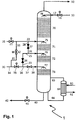
- Fig. 1 shows schematically a methanol-water separating column 1 within the detergent work-up of a plant operating according to the Rectisol process for scrubbing raw synthesis gas with cryogenic methanol.
- Regenerated methanol washing agent from the hot methanol regeneration (not shown in the figure) is fed via line 10, control valve 11 and line 12 to the separating column and this is applied to the upper part of the column near the top of the column via liquid distributor 78.
- a methanol-water mixture likewise originating from the hot methanol regeneration, is fed to the separating column 1 via line 20, control valve 21 and line 22 and this mixture is applied in the middle region of the column via liquid distributor 75.
- the separating column 1 is equipped with structured packing segments 70, 71, 72, 73, with the aid of which the vapor-liquid equilibrium of the components involved is established.
- the separating column could also be equipped with trays or packed beds; this has no significant influence on the functioning of the invention.
- the energy supply required for the distillative separation of the methanol-water mixture is ensured via reboiler 60, in which part of the bottom product brought in via line 66 evaporates and the steam or the heated vapor-liquid mixture is returned via line 65 to the separation column.
- the reboiler is heated by means of steam which is fed to the reboiler via line 61.
- the resulting condensate is discharged via line 62.
- water-depleted methanol vapor is drawn off from the top of the separating column and returned to the hot methanol regeneration.
- the water-enriched bottom product is discharged via line 40, control valve 41 and line 42.
- the bottom product is fed to a work-up (not shown in the figure) or removed from the process.
- demineralized water is now also supplied via line 30.
- this comes from a gas scrubber, with the help of which traces of methanol were removed from the CO 2 stream discharged from the Rectisol system before it was released into the atmosphere.
- the demineralized water is discharged via line 34, control valve 35, line 36, shut-off valve 37 and line 38 to the separating column 1 and this is given up via liquid value regulator 77.
- the entire water flow brought in via line 30 can also be passed via line 31, control valve 32 and line 33 to the methanol-water mixture brought in via line 20 and merged with this in line 22.
- the water flow or partial flow then enters the separating coke, together with the methanol-water mixture, via liquid distributor 75.
- shut-off valves 24, 27 , 37 By opening or closing the shut-off valves 24, 27 , 37, a partial flow can also be introduced into the separating column via the line path 30, 34, 36) 23, 25 and liquid distributor 76. It is also possible to supply water via the conduit 26, 28, 22. In order to enable further regulation or better distribution of the water to the liquid distributor, one or more shut-off valves can also be replaced by control valves.
- the selection of the water addition points via the liquid distributors 75, 76, 77 depends in particular on which parts of the separating column are particularly severely affected by deposits or caking of metal sulfide particles. This is based on appropriate operating experience or can be determined through appropriate tests without adding water.
- the invention provides a gas scrubbing process for separating acidic gas constituents from synthesis gas containing metal carbonyls, which makes it possible to safely discharge the metal sulfide particles formed from the metal carbonyls via the column bottom of the methanol-water separation column without caking or caking in the column and without the need for additional equipment such as precipitation tanks.
Description
Die Erfindung betrifft ein Verfahren zur Abtrennung unerwünschter, insbesondere acider Gasbestandteile, beispielsweise Kohlendioxid und Schwefelwasserstoff, aus einem Metallcarbonyle enthaltendem Rohsynthesegas durch Gaswäsche mit einem Waschmittel. Die Erfindung betrifft ferner eine Anlage zur Durchführung eines solchen Verfahrens.The invention relates to a method for separating undesired, in particular acidic gas constituents, for example carbon dioxide and hydrogen sulfide, from a crude synthesis gas containing metal carbonyls by scrubbing the gas with a washing agent. The invention also relates to a system for carrying out such a method.
Verfahren zur Abtrennung von unerwünschten Begleitstoffen aus technischen Rohgasen mittels physikalischer oder chemischer Absorption oder Gaswäsche sind aus dem Stand der Technik wohlbekannt. So können mit solchen Verfahren unerwünschte, acide Bestandteile aus durch Vergasung oder Reformierung von kohlenstoffhaltigen Einsatzstoffen erzeugten Rohsynthesegasen, beispielsweise Kohlendioxid (CO2) und Schwefelwasserstoff (H2S), aber auch weitere Bestandteile wie Carbonylsulfid (COS) und Cyanwasserstoff (HCN), von den erwünschten Synthesegasbestandteilen Wasserstoff (H2) und Kohlenmonoxid (CO) sicher bis in den Spurenbereich entfernt werden. Ein bekanntes und häufig angewendetes Verfahren ist das Rectisol-Verfahren, das in
Das als Waschmittel verwendete, mit den Störkomponenten beladene Methanol wird im Rectisol-Verfahren über Regenerierungsvorrichtungen im Kreis gefahren. In den Regenerierungsvorrichtungen wird das beladene Methanol von den absorbierten Gasen auf physikalischem Wege befreit. Dabei wird in einem ersten Regenerierungsschritt CO2 durch Druckentspannung (sogenannte Flashregenerierung) und/oder Strippen mit einem Gas, beispielsweise Stickstoff, aus dem beladenen Methanol-Waschmittel entfernt. In einem weiteren oder alternativen Regenerierungsschritt werden die schwefelhaltigen Gase, COS und H2S, durch Erhitzen abgetrieben (sogenannte Heissregenerierung), Häufig wird angestrebt, ein möglichst CO2-freies COS/H2S-Gas zu erzeugen, da dessen wirtschaftlich interessante Weiterverarbeitung durch eine Vermischung mit CO2 beeinträchtigt wird.The methanol used as detergent and loaded with the interfering components is circulated in the Rectisol process via regeneration devices. In the regeneration devices, the loaded methanol is physically freed from the absorbed gases. In this case, in a first regeneration step, CO 2 is removed from the loaded methanol washing agent by pressure release (so-called flash regeneration) and / or stripping with a gas, for example nitrogen. In a further or alternative regeneration step, the sulphurous gases, COS and H 2 S, are driven off by heating (so-called hot regeneration). Often, the aim is to produce a CO 2 -free COS / H 2 S gas, as its further processing is economically interesting is adversely affected by mixing with CO 2 .
Beim Rectisol-Verfahren wird zwischen dem Standardverfahren und dem selektiven Rectisol-Verfahren unterschieden. Bei dem Standard-Rectisol-Verfahren werden die Begleitgase COS/H2S und das CO2 gemeinsam in einem Absorptionsschritt aus dem Rohsynthesegas abgetrennt. Dagegen werden bei dem sogenannten selektiven Rectisol-Verfahren die schwefelhaltigen Begleitgase COS/H2S und das CO2 jeweils in separaten, nacheinander ablaufenden Absorptionsschritten aus dem Rohsynthesegas abgetrennt. Diese selektive Absorption wird durch geeignete Einstellung der Verfahrensparameter, insbesondere des Mengenverhältnisses von Waschmittel und zu absorbierendem Gas, ermöglicht. Der Vorteil der selektiven Absorption liegt darin, dass das COS/H2S- und das CO2-Gas schon bei der Absorption zum größten Teil getrennt gehalten werden und nur der kleinere Teil bei der Regenerierung des Methanols getrennt werden muss. Auf diese Weise wird zudem die Gewinnung des enthaltenen Schwefels mit Hilfe von nachgeschalteten Verfahren wie beispielsweise dem Claus-Verfahren ermöglicht.In the Rectisol process, a distinction is made between the standard process and the selective Rectisol process. In the standard Rectisol process, the associated gases COS / H 2 S and the CO 2 are separated from the raw synthesis gas together in an absorption step. In contrast, in the so-called selective Rectisol process, the sulfur-containing accompanying gases COS / H 2 S and the CO 2 are each in separate, sequential absorption steps separated from the raw synthesis gas. This selective absorption is made possible by suitable setting of the process parameters, in particular the quantitative ratio of detergent and gas to be absorbed. The advantage of selective absorption is that most of the COS / H 2 S and CO 2 gas are kept separate during absorption and only the smaller part has to be separated during the regeneration of the methanol. This also enables the sulfur contained to be recovered with the aid of downstream processes such as the Claus process.
Nach Durchlaufen von zumeist mehreren Regenerierungsschritten werden mehrere Teilströme des von den Störkomponenten befreite Waschmittels, beim Rectisol-Verfahren also klassischerweise das Methanol, zu der Absorberkolonne zurückgeführt. Das durch Heissregenerierung regenerierte Waschmittel weist dabei die höchste Reinheit auf und wird daher zur Feinwäsche bzw. Feinabsorption von bereits vorgereinigtem Synthesegas verwendet; es stellt somit die abschließende Waschstufe dar, bevor das gereinigte Synthesegas als Reinsynthesegas die Absorberkolonne üblicherweise an deren oberem Ende verlässt. Das durch Flashregenerierung regenerierte Waschmittel weist eine etwas geringere Reinheit auf und ist insbesondere noch mit Kohlendioxid teilbeladen. Dieses Waschmittel wird in der sogenannten CO2-Hauptwäsche eingesetzt, die aus der Perspektive des die Absorberkolonne durchlaufenden Synthesegases stromaufwärts der Feinwäsche angeordnet ist, üblicherweise also unterhalb der Feinwäschestufe.After passing through mostly several regeneration steps, several substreams of the detergent freed from the interfering components, in the Rectisol process that is traditionally the methanol, are returned to the absorber column. The detergent regenerated by hot regeneration has the highest purity and is therefore used for fine washing or fine absorption of already pre-cleaned synthesis gas; it thus represents the final scrubbing stage before the purified synthesis gas leaves the absorber column as pure synthesis gas, usually at its upper end. The detergent regenerated by flash regeneration has a somewhat lower purity and, in particular, is still partially loaded with carbon dioxide. This detergent is used in what is known as the CO 2 main wash, which, from the perspective of the synthesis gas flowing through the absorber column, is arranged upstream of the delicates, that is usually below the delicates stage.
Als Sumpfprodukt der Heissregenerierung wird ein wasserhaltiger Methanolstrom erhalten, der zu einer Methanol-Wasser-Trennkolonne geführt und dort destillativ aufgetrennt wird. Als Kopfprodukt dieser Destillation wir ein Methanolstrom erhalten, der an Wasser abgereichert ist und in das Verfahren zurückgeführt wird. Das als Sumpfprodukt erhaltene Wasser wird aus dem Verfahren ausgeleitet.A water-containing methanol stream is obtained as the bottom product of the hot regeneration, which is fed to a methanol-water separation column and separated there by distillation. The overhead product of this distillation is a stream of methanol which has been depleted in water and is returned to the process. The water obtained as the bottom product is discharged from the process.
Es ist bekannt, dass bei der Herstellung von Synthesegas aus schwermetallhaltigen Brennstoffen Metallcarbonyle entstehen, die den Einsatz von Synthesegas bei einer Vielzahl von chemischen Synthesen beeinträchtigen. Aus diesen Metallcarbonylen entstehen innerhalb des Rectisol-Verfahrens in Gegenwart von H2S feindisperse bzw. kolloidale Metallsulfide, die an ihnen zugänglichen Oberflächen anbacken, was in kurzer Zeit zu Verlegungen oder Verstopfungen der betroffenen Anlagenteile führt. Besonders in der Heissregenerierung bestehen aufgrund der dort herrschenden Temperaturen und der Anwesenheit von H2S günstige Bedingungen zum Zersetzen der im Methanol gelösten Metallcarbonyle und der nachfolgenden Bildung der entsprechenden Metallsulfide.It is known that in the production of synthesis gas from fuels containing heavy metals, metal carbonyls are formed which impair the use of synthesis gas in a large number of chemical syntheses. In the Rectisol process in the presence of H 2 S, these metal carbonyls are converted into finely dispersed or colloidal metal sulfides, which stick to the surfaces accessible to them, which in a short time leads to relocations or blockages of the affected parts of the plant. In hot regeneration in particular, the temperatures prevailing there and the presence of H 2 S give rise to favorable conditions for decomposing the metal carbonyls dissolved in the methanol and the subsequent formation of the corresponding metal sulfides.
Ein Verfahren zum Reinigen von Metallcarbonyle enthaltendem Synthesegas durch eine Tieftemperaturgaswäsche mit Methanol und anschließende Regenerierung des Methanols durch Entspannen, Evakuieren, Austreiben und Erhitzen mit zusätzlicher Behandlung in einem Vorreaktor ist in der deutschen Patentschrift
Ein weiteres Verfahren zur Entfernung von Metallcarbonylverbindungen im Rahmen des Reinigens von Synthesegasen durch Tieftemperaturgaswäsche ist aus der deutschen Offenlegungsschrift
Die Entfernung der aus den Metallcarbonylen, d. h. vor allem aus dem Eisenpentacarbonyl Fe(CO)5 und dem Nickeltetracarbonyl Ni(CO)4 entstehenden, feindispersen oder kolloidalen Metallsulfiden ist deshalb bei der Rectisol-Gaswäsche ein dringliches Problem, um ihre Ablagerungen in der Trennkolonne und anderen Anlagenteilen zu verhindern. Für die meisten der gefährdeten Anlagenteile sind inzwischen schon Lösungen erarbeitet worden, die eine Reinigung während der planmäßigen Stillstände ermöglichen. Die Lösungen zur Beherrschung von Ablagerungen von kolloidalen Metallsulfiden auf den Böden der Methanol-Wasser-Kolonne sind bislang noch verbesserungsfähig.The removal of the finely dispersed or colloidal metal sulfides formed from the metal carbonyls, i.e. above all from the iron pentacarbonyl Fe (CO) 5 and the nickel tetracarbonyl Ni (CO) 4 , is therefore an urgent problem in Rectisol gas scrubbing in order to remove their deposits in the separating column and to prevent other parts of the system. For most of the endangered parts of the plant, solutions have already been developed that enable cleaning during scheduled shutdowns. The solutions for controlling deposits of colloidal metal sulphides on the bottoms of the methanol-water column can still be improved.
In der deutschen Patentschrift
Aufgabe der Erfindung ist es daher, ein Verfahren anzugeben, das die genannten Nachteile der aus dem Stand der Technik bekannten Verfahren vermeidet und bei dem insbesondere die Metallsulfide entweder beseitigt oder in eine Form überführt werden, die nicht mehr zu Anbackungen in den verschiedenen Geräteteilen und den Kolonnenböden führt.The object of the invention is therefore to provide a method which avoids the mentioned disadvantages of the methods known from the prior art and in which in particular the metal sulfides are either removed or converted into a form that no longer causes caking in the various parts of the device and the Column trays leads.
Diese Aufgabe wird durch ein Verfahren mit den Merkmalen des Anspruchs 1 gelöst. Weitere, insbesondere bevorzugte Ausgestaltungen des erfindungsgemäßen Verfahrens finden sich in den Unteransprüchen, Die Erfindung betrifft ferner eine Anlage zur Durchführung eines solchen Verfahrens (Anspruch 10).This object is achieved by a method with the features of
Unter einer Zugabe von Wasser direkt in die Zuleitung zu der Methanol-Wasser-Trennkohnne wird die Abwesenheit von Misch-, Puffer-, Fällungs- öder sonstig gen Behältern verstanden, die dem Inkontaktbringen des zugegebenen Wassers mit dem wasserhaltigen Methanol vor Eintritt in die Trennkolonne dienen.An addition of water directly into the feed line to the methanol-water separator is understood to mean the absence of mixing, buffer, precipitation or other containers which are used to bring the added water into contact with the water-containing methanol before entering the separating column .
Unter einer methanolreichen oder wasserreichen Umgebung wird eine flössige Phase verstanden, in der die jeweilige Komponente überwiegt und insbesondere eine höhere Konzentration aufweist als die andere Komponente. Ein Methanol und Wasser enthaltendes. Stoffsystem würde demnach als methanolreich bezeichnet, wenn der Stoffmengenanteil an Methanol größer ist als derjenige von Wasser.A methanol-rich or water-rich environment is understood to mean a liquid phase in which the respective component predominates and in particular has a higher concentration than the other component. A containing methanol and water. The substance system would therefore be described as rich in methanol if the molar proportion of methanol is greater than that of water.
Der Fachmann ist in der Lage, den Grad der Überführung der Metafisulfide von einer methanolreichen oder wasserreichen Umgebung durch Probenahme und Routinemessungen zu messen. Entsprechende Analysenverfahren sind aus dem Stand der Technik bekannt.The person skilled in the art is able to measure the degree of transfer of the metafisulfides from a methanol-rich or water-rich environment by sampling and routine measurements. Appropriate analytical methods are known from the prior art.
Unter Fluidverbindung zwischen zwei Bereichen wird jegliche Art von Verbindung verstanden, die es ermöglicht, dass ein Fluid, beispielsweise das flüssige Waschmittel, von dem einen zu dem anderen der beiden B strömen kann, unbeachtlich etwaiger zwischengeschalteter Bereiche, Bauteile. Armaturen oder Vorrichtungen.Fluid connection between two areas is understood to mean any type of connection which enables a fluid, for example the liquid detergent, to flow from one of the two B to the other, regardless of any interposed areas, components. Fittings or fixtures.
Etwaige Druckangaben in der Einheit bar(a) beziehen sich auf den Absolutdruck in bar, absolut, sofern nicht im Einzelfall anders angegeben.Any pressure specifications in the unit bar (a) refer to the absolute pressure in bar, absolute, unless otherwise stated in the individual case.
Der Erfindung liegt die Erkenntnis zugrunde, dass Metallsulfidpartikel in methanolreicher Umgebung und wasserreicher Umgebung ein unterschieldliches Verhalten aufweisen. In methanolreicher Umgebung bleiben die Metallsulfidpartikel überwiegend dispergiert, weisen also nur wenig Sedmentationsneigung auf, aber besitzen eine Neigung zur Adhäsion an Oberflächen. In wasserreicher Umgebung erfolgt dagegen bevorzugt eine Agglomeration kleiner Metallsulfidpartikel zu größeren Aggregaten, die ausfallen und keine oder nur eine geringere Adhäsionsneigung aufweisen. Überraschenderweise kann dieser Effekt direkt in der Methanol-Wasser6-Trennkolonne ausgenutzt werden. ohne das ein Vorschalten eines Fällungsbehälters erforderlich ist.The invention is based on the knowledge that metal sulfide particles behave differently in a methanol-rich environment and a water-rich environment. In In an environment rich in methanol, the metal sulfide particles remain predominantly dispersed, so they have little tendency to sedment, but have a tendency to adhere to surfaces. In a water-rich environment, on the other hand, there is preferably an agglomeration of small metal sulfide particles to form larger aggregates, which precipitate and have little or no tendency to adhesion. Surprisingly, this effect can be used directly in the methanol-water6 separation column. without the need to connect a precipitation container upstream.
Eine bevorzugte Ausgestaltung des erfindungsgemäßen Verfahrens ist dadurch gekennzeichnet, dass bei den Verfahrensschritten e) oder f) die Zugabe von Wasser in der Weise erfolgt, dass die Verweilzeit der erhaltenen Mischung in der Zuleitung vor Einleiten in die Metharrol-Wasser-Trennkokanne ausreicht, um eine Oberführung der Metallsulfide von mindestens 50 %, bevorzugt mindestens 90 %. meist bevorzugt mindestens 95 % von einer methanolreichen Umgebung in eine wasserreiche Umgebung zu bewirken. Bei der Überführung der Metallsulfidpartikel von der methanolrichen Umgebung in eine wasserreiche Umgebung wird das oben dargelegte Verhalten der Metallsulfidpartikel beobachtet dass umso ausgeprägter auftritt, je vollständiger die Überführung der Metallsulfide verläuft. Entsprechend sinkt mit zunehmendem Überführungsgrad der Restgehalt an Metallsulfidpartikeln in der methanolreichen Umgebung und somit auch die Gefahr der Bildung von Anbackungen in Testen der Methanol-Wasser-Kolonne.A preferred embodiment of the process according to the invention is characterized in that in process steps e) or f) the addition of water takes place in such a way that the residence time of the mixture obtained in the feed line before it is introduced into the metharole-water separating kettle is sufficient to allow a Conversion of the metal sulfides of at least 50%, preferably at least 90%. most preferably to effect at least 95% from a methanol-rich environment to a water-rich environment. When the metal sulfide particles are transferred from the methanol-rich environment to a water-rich environment, the behavior of the metal sulfide particles set out above is observed that the more pronounced the more complete the conversion of the metal sulfides, the more pronounced it occurs. Correspondingly, as the degree of conversion increases, the residual content of metal sulfide particles in the methanol-rich environment decreases and thus also the risk of caking in tests of the methanol-water column.
Als besonders vorteilhaft hat es sich herausgestellt wenn sich beim Verfahrensschritt e) oder f)
die Zugabestelle des Wassers in die Zuleitung des an aciden Gasbestandteilen abgereicherten, Wasser und Metallsulfide enthaltenden Methanol-Teilstroms so angeordnet wird, dass eine Verweilzeit von mindestens 5 s, vorzugsweise mindestens 10 s vor Eintritt in die Methanol-Wasser-Trennkolonne eingehalten wird, wobei die Strömungsgeschwindigkeit des Methanol-Wasser-Gemischs in der Zuleitung zwischen 0,5 und 2,0 m/s, bevorzugt zwischen 1,0 und 1,5 m/s beträgt. Untersuchungen zeigen, dass bei Berücksichtigung dieser Kriterien eine besonders effektive Abtrennung der Metallsulfidpartikel gemeinsam mit dem wasserhaltigen Sumpfprodukt der Methanol-Wasser-Trennkolonne möglich ist.It has been found to be particularly advantageous if in process step e) or f)
the point of addition of the water into the feed line of the methanol substream, which is depleted in acidic gas constituents and containing water and metal sulfides, is arranged such that a residence time of at least 5 s, preferably at least 10 s, is maintained before entry into the methanol-water separation column, the The flow rate of the methanol-water mixture in the feed line is between 0.5 and 2.0 m / s, preferably between 1.0 and 1.5 m / s. Research shows that when taken into account these criteria allow a particularly effective separation of the metal sulfide particles together with the water-containing bottom product of the methanol-water separation column.
In der Praxis ergibt es sich, dass bei einer Anordnung der Zugabestelle des Wassers in die Zuleitung mindestens 5 m stromaufwärts der Methanol-Wasser-Trennkolonne zumeist eine gute Durchmischung erhalten wird.In practice, it is found that if the point of addition of the water is arranged in the feed line at least 5 m upstream of the methanol-water separation column, thorough mixing is usually obtained.
In bevorzugter Verfahrenausgestaltung beträgt beim Verfahrensschritt f) die durch direktes Einspritzen in die Methanol-Wasser-Trennkolonne an mindestens einer Stelle zugegebene Wassetmenge zwischen 3 und 50 %, bevorzugt zwischen 5 und 15 % dar Feedmenge der Methanol-Wasser-Trennkolonne, also der zugeführten Menge des aufzutrennenden Methanol-Wasser-Gemischs. Untersuchungen zeigen, dass bei Einhalten dieser Mindestinjektionsmenge eine besonders effektive Abtrennung der Metallsulfidpartikel gemeinsam mit dem wasserhaltigen Sumpfprodukt der Methanol-Wasser-Trennkolonne möglich ist.In a preferred embodiment of the method, the amount of water added by direct injection into the methanol-water separation column at at least one point is between 3 and 50%, preferably between 5 and 15% of the feed amount of the methanol-water separation column, i.e. the amount added of the methanol-water mixture to be separated. Investigations show that if this minimum injection amount is observed, a particularly effective separation of the metal sulfide particles together with the water-containing bottom product of the methanol-water separation column is possible.
Aus Betriebserfahrungen geht hervor, dass unter üblichen Betriebsbedingungen der Methanol-Wasser-Trennkolonne bei einem Einspritzen von mindestens 100 l/h Wasser pro Injektionspunkt die Bildung von Anbackungen bzw. Ablagerungen durch Metallsulfide sicher verhindert wird.Operating experience shows that under normal operating conditions of the methanol-water separation column, with an injection of at least 100 l / h of water per injection point, the formation of caking or deposits due to metal sulfides is reliably prevented.
In einem weiteren Aspekt des erfindungsgemäßen Verfahrens werden die Metallsulfide mit dem wasserhaltigen Sumpfprodukt der Methanol-Wasser-Trennkolonne aus dem Verfahren ausgeleitet. Dies ist mögich, da es trotz der erhöhten Agglomerationsnigung kleiner Metallsulfidpartikel zu größeren Aggregaten in der wasserreichen Umgebung überraschenderweise nicht zur Bildung sehr großer, nicht mehr aus dem Kolonnensumpf ausleitbarer Metallsulfidaggregate kommt. Vielmehr können die Metallsulfidpartikel problemlos gemeinsam mit dem wasserhaltigen Sumpfprodukt der Methanol-Wasser-Trannkolonne mit üblichen Fördervorrichtungen, beispielsweise Pumpen, aus dem Verfahren ausgeleitet werden.In a further aspect of the process according to the invention, the metal sulfides are discharged from the process with the water-containing bottom product of the methanol-water separation column. This is possible because despite the increased tendency of small metal sulfide particles to agglomerate to form larger aggregates in the water-rich environment, surprisingly, there is no formation of very large metal sulfide aggregates that can no longer be discharged from the column bottom. Rather, the metal sulfide particles can easily be discharged from the process together with the water-containing bottom product of the methanol-water trapping column using conventional conveying devices, for example pumps.
Eine weitere, bevorzugte Verfahrensausgestaltung ist dadurch gekennzeichnet. dass für die Wasserzugabe in Verfahrensschritt e) oder f) mindestens ein wasserhaltiger Strom ausgewählt aus der folgenden Gruppe verwendet wird: Wasser aus einem CO2-Abgaswäscher, Sumpfprodukt der Methanol-Wasser-Trennkolonne, Frischwasser, demineralisiertes Wasser. Alle diese wasserhaltigen Ströme sind geeignet, um das oben beschriebene Agglomerationsverhalten der Metallsulfidpartikel hervorzurufen. Dies gilt für die jeweiligen wasserhaltigen Ströme allein oder in Mischung mit anderen wasserhaltigen Ströme aus der genannten Gruppe.Another preferred embodiment of the method is characterized. that at least one water-containing stream selected from the following group is used for adding water in process step e) or f): water from a CO 2 exhaust gas scrubber, bottom product of the methanol-water separation column, fresh water, demineralized water. All of these water-containing streams are suitable for producing the agglomeration behavior of the metal sulfide particles described above. This applies to the respective water-containing streams alone or in a mixture with other water-containing streams from the group mentioned.
In weiterer bevorzugter Verfahrensausgestaltung weist der für die Wasserzugabe in Verfahrensschritt e) oder f) verwendete Wasserstrom eine Temperatur zwischen 10 und 1140 °C, bevorzugt zwischen 60 und 120 °C auf. Untersuchungen zeigen, dass innerhalb der genannten Temperaturbereiche eine besonders effektive Abtrennung der Metallsulfidpartikel gemeinsam mit dem wasserhaltigen Sumpfprodukt der Methanol-Wasser-Trennkölonne möglich ist.In a further preferred embodiment of the process, the water stream used for adding water in process step e) or f) has a temperature between 10 and 1140.degree. C., preferably between 60 and 120.degree. Investigations show that within the specified temperature ranges a particularly effective separation of the metal sulfide particles together with the water-containing bottom product of the methanol-water separation column is possible.
Weitere Merkmale, Vorteile und Anwendungsmöglichkeiten der Erfindung ergeben sich auch aus der nachfolgenden Beschreibung eines Ausführungs- und Zahlenbeispiels und der Zeichnung.Further features, advantages and possible applications of the invention can also be found in the following description of an exemplary embodiment and numerical example and the drawing.
- Fig. 1Fig. 1
- eine schematische Darstellung einer beispielhaften Ausgestaltung des erfindungsgemäßen Verfahrens bzw. der erfindungsgemäßen Anlage.a schematic representation of an exemplary embodiment of the method according to the invention or the system according to the invention.
Über Leitung 10, Regelventil 11 und Leitung 12 wird regeneriertes Methanol-Waschmittel aus der Methanol-Heissregenerierung (in der Figur bildlich nicht dargestellt) zu der Trennkolonne geführt und dieser in deren oberen Teil in der Nähe des Kolonnenkopfs über Flüssigkeitsverteiler 78 aufgegeben. Ferner zu wird der Trennkolonne 1 über Leitung 20, Regelventil 21 und Leitung 22 ein ebenfalls aus der Methanol-Heissregenerierung stammendes Methanol-Wasser-Gemisch herangeführt und dieser im mittleren Kolonnenbereich über Flüssigkeitsverteiler 75 aufgegeben.Regenerated methanol washing agent from the hot methanol regeneration (not shown in the figure) is fed via
Die Trennkolonne 1 ist im vorliegenden Ausführungsbeispiel mit strukturierten Packungssegmenten 70, 71, 72, 73 ausgestattet, mit deren Hilfe die Einstellung des Dampf-Flüssigkeits-Gleichgewichts der beteiligten Komponenten erfolgt. Alternativ könnte die Trennkolonne auch mit Böden oder Füllkörperschüttungen ausgestattet werden; dies hat keinen wesentlichen Einfluss auf die Funktionsweise der Erfindung. Die für die destillative Auftrennung des Methanol-Wasser-Gemischs erforderliche Energiezufuhr wird über Aufkocher 60 gewährleistet, in dem ein Teil des über Leitung 66 herangeführten Sumpfprodukts verdampft und der Dampf bzw. das erhitzte Dampf-Flüssigkeitsgemisch über Leitung 65 zu der Trennkolonne zurückgeführt wird. Die Beheizung des Aufkochers erfolgt mittels Wasserdampf, der über Leitung 61 dem Aufkocher aufgegeben wird. Das dabei anfallende Kondensat wird über Leitung 62 abgeführt.In the present exemplary embodiment, the separating
Über Leitung 50 wird vom Kopf der Trennkolonne an Wasser abgereicherter Methanoldampf abgezogen und zu der Methanol-Heissregenerierung zurückgeführt. Das Ausleiten des an Wasser angereicherten Sumpfprodukts erfolgt über Leitung 40, Regelventil 41 und Leitung 42. Das Sumpfprodukt wird einer in der Figur nicht bildlich dargestellten Aufarbeitung zugeführt oder aus dem Verfahren entfernt.Via
Erfindungsgemäß wird nun zusätzlich über Leitung 30 demineralisiertes Wasser herangeführt. Dieses stammt im vorliegenden Beispiel aus einem Gaswäscher, mit dessen Hilfe Methanolspuren aus dem aus der Rectisol-Anlage ausgeführten CO2-Strom vor dessen Abgabe an die Atmosphäre entfernt wurden, Das deminerallslerte Wasser wird über Leitung 34, Regelventil 35, Leitung 36, Absperrventil 37 und Leitung 38 zu der Trennkolonne 1 geführt und dieser über Flüssigkeitswerteiller 77 aufgegeben.According to the invention, demineralized water is now also supplied via
Zusätzlich wird ein Teilstrom des über Leitung 30 herangef¨hrten Wasserstroms über Leitung 31, Regelventil 32 und Leitung 33 zu dem über Leitung 20 hefangeführten Methanol-Wasser-Gemisch geletel und mit diesem in Leitung 22 zusammengeführtIn addition, a partial flow of the water flow brought in via
Auch kann der gesamte über Leitung 30 herangeführte Wasserstrom über Leitung 31, Regelventil 32 und Leitung 33 zu dem über Leitung 20 herangeführten Methanol-Wasser-Gemisch geleitet und mit diesem in Leitung 22 zusammengeführt werden.The entire water flow brought in via
Der Wasserstrom oder Teilstrom tritt dann gef meinsam mit dem Methanol-Wasser-Gemi=h über Flüssigkeitsverteiler 75 in die Trennkokonne ein.The water flow or partial flow then enters the separating coke, together with the methanol-water mixture, via
Ferner kann durch entsprechendes Öffnen bzw. Schießen der Absperrventile 24, 27i 37 auch ein Teistrom über den Leitungweg 30. 34. 36) 23, 25 und Flüssigkeitsverteiler 76 in die Trennkolonne eingebracht werden. Auch die Wasserzufuhr über den Leitungsweg 26, 28, 22 ist möglich. Um eine fernere Regulier rung bzw, bessere Verteilung des Wassers auf die Flüssigkeitsverteiler zu enrmöglichen, können ein oder mehrere Absperrventile auch durch Regelventile ersetzt werden.Furthermore, by opening or closing the shut-off
Die Auswahl der Wasserzugabestellen über die Flüssigkeitsverteiler 75, 76, 77 wind insbesondere davon abhängen, weiche Teile der Trennkolonne besonders stark durch Ablagerungen oder Anbackungen von Metallsulfidpartikeln betroffen sind. Dies basiert auf entsprechender Betriebserfahrung oder kann durch entsprechende Versuche ohne Wasserrugabe ermittelt werden.The selection of the water addition points via the
Mit der Erfindung wird ein Gaswaschverfahren zur Abtrennung acider Gasbestandteile aus Metallcarbonyle enthaltendem Synthesegas zur Verfügung gestellt, das es ermöglicht, die aus den Metallcarbonylen entstehenden Metallsulfidpartikel sicher über den Kolonnensumpf der Methanol-Wasser-Trennkolonne auszuleiten, ohne dass es in dieser zu Anbackungen oder Verlegungen kommt und ohne dass zusätzliche Ausrüstungsteile wie beispielsweise Fällungsbehälter benötigt werden.The invention provides a gas scrubbing process for separating acidic gas constituents from synthesis gas containing metal carbonyls, which makes it possible to safely discharge the metal sulfide particles formed from the metal carbonyls via the column bottom of the methanol-water separation column without caking or caking in the column and without the need for additional equipment such as precipitation tanks.
- 11
- TrennkolonneSeparation column
- 1010
- Leitungmanagement
- 1111
- RegelventilControl valve
- 1212
- Leitungmanagement
- 2020th
- Leitungmanagement
- 2121st
- RegelventilControl valve
- 2222nd
- Leitungmanagement
- 2323
- Leitungmanagement
- 2424
- AbsperrventilShut-off valve
- 2525th
- Leitungmanagement
- 2626th
- Leitungmanagement
- 2727
- AbsperrventilShut-off valve
- 2828
- Leitungmanagement
- 3030th
- Leitungmanagement
- 3131
- Leitungmanagement
- 3232
- RegelventilControl valve
- 3333
- Leitungmanagement
- 3434
- Leitungmanagement
- 3535
- RegelventilControl valve
- 3636
- Leitungmanagement
- 3737
- AbsperrventilShut-off valve
- 3838
- Leitungmanagement
- 4040
- Leitungmanagement
- 4141
- RegelventilControl valve
- 4242
- Leitungmanagement
- 5050
- Leitungmanagement
- 6060
- AufkocherReboiler
- 6161
- Leitungmanagement
- 6262
- Leitungmanagement
- 6565
- Leitungmanagement
- 6666
- Leitungmanagement
- 7070
- strukturierte Packungstructured packing
- 7171
- strukturierte Packungstructured packing
- 7272
- strukturierte Packungstructured packing
- 7373
- strukturierte Packungstructured packing
- 7575
- FlüssigkeitsverteilerLiquid distributor
- 7676
- FlüssigkeitsverteilerLiquid distributor
- 7777
- FlüssigkeitsverteilerLiquid distributor
- 7878
- FlüssigkeitsverteilerLiquid distributor
Claims (10)
- Process for removal of carbon dioxide (CO2) and hydrogen sulfide (H2S) from a crude synthesis gas containing CO2, H2S, water and metal carbonyls, with methanol as scrubbing medium, comprising the following steps:a) feeding the crude synthesis gas to an absorption device,b) bringing the crude synthesis gas into contact with a cold methanol part-stream and with at least one further methanol part-stream returned from downstream process steps in the absorption device, wherein a product gas stream depleted of acidic gas components, water and metal carbonyls is obtained and is discharged from the process, and wherein a methanol part-stream laden with acidic gas components, water and metal carbonyls is obtained,c) regenerating the laden methanol part-stream in multiple stages by pressure reduction (flashing) and/or temperature increase (hot regeneration), wherein at least one regenerated methanol part-stream is obtained which is returned to process step b), wherein furthermore one or more gas streams containing carbon dioxide and/or hydrogen sulfide are obtained and are discharged from the process, and wherein a methanol part-stream depleted of acidic gas components and containing water and metal sulfides is obtained,d) introducing the methanol part-stream depleted of acidic gas components and containing water and metal sulfides into a methanol/water separating column, separating the said part-stream by distillation in the methanol/water separating column into a methanol-containing top product, which is at least partially returned to process step b) and/or step c), and into a water-containing bottom product, which is discharged from the process, characterised in thate) water is added directly into the feed line of the methanol part-stream depleted of acidic gas components and containing water and metal sulfides before the introduction of the part-stream into the methanol/water separating column, or in thatf) water is added directly into the feed line of the methanol part-stream depleted of acidic gas components and containing water and metal sulfides before the introduction of the part-stream into the methanol/water separating column, and water is injected directly into the methanol/water separating column at at least one point, wherein an addition of water directly into the feed line to the methanol/water separating column is understood as the absence of containers for mixing, buffering, precipitation or other purposes which serve to bring the added water into contact with the water-containing methanol before entry into the separating column.
- Process according to claim 1, characterised in that in process step e) or f) the addition of water takes place in such a way that the residence time of the obtained mixture in the feed line before introduction into the methanol/water separating column is sufficient to cause a transfer of at least 50%, preferably at least 90%, most preferably at least 95% of the metal sulfides from a methanol-rich environment into a water-rich environment.
- Process according to claim 1 or 2, characterised in that in process step e) the point where the water is added into the feed line of the methanol part-stream depleted of acidic gas components and containing water and metal sulfides is arranged so that a residence time of at least 5 s, preferably at least 10 s before entry into the methanol/water separating column is maintained, wherein the flow velocity of the methanol/water mixture in the feed line is between 0.5 and 2.0 m/s, preferably between 1.0 and 1.5 m/s.
- Process according to claim 3, characterised in that in process step e) the point where the water is added into the feed line of the methanol part-stream depleted of acidic gas components and containing water and metal sulfides is located at least 5 m upstream of the methanol/water separating column.
- Process according to any of the preceding claims, characterised in that in process step f) the quantity of water added by direct injection into the methanol/water separating column at at least one point is between 3 and 50 %, preferably between 5 and 15 % of the feed quantity of the methanol/water separating column.
- Process according to claim 5, characterised in that at least 100 l/h water are injected per injection point.
- Process according to any of the preceding claims, characterised in that the metal sulfides are discharged from the process with the water-containing bottom product of the methanol/water separating column.
- Process according to any of the preceding claims, characterised in that for the addition of water in process step e) or f) at least one water-containing stream selected from the following group is used: water from a CO2 flue gas scrubber, bottom product from the methanol/water separating column, fresh water, demineralised water.
- Process according to any of the preceding claims, characterised in that the water stream used for the addition of water in process step e) or f) has a temperature between 10 and 140°C, preferably between 60 and 120°C.
- Apparatus for removal of carbon dioxide (CO2) and hydrogen sulfide (H2S) from a crude synthesis gas containing CO2, H2S, water and metal carbonyls with methanol as scrubbing medium, comprising the following components and assemblies in fluidic communication with one another:a) means for feeding the crude synthesis gas to an absorption device,b) an absorption device, means for feeding the crude synthesis gas, a cold methanol part-stream and at least one further methanol part-stream returned from downstream process steps to the absorption device, means for discharging a product gas stream which is depleted of acidic gas components, water and metal carbonyls and a methanol part-stream which is laden with acidic gas components, water and metal carbonyls,c) one or more devices for multi-stage regeneration of the laden methanol part-stream by pressure reduction (flashing) and/or temperature increase (hot regeneration), means for feeding the laden methanol part-stream to the regeneration devices, means for returning at least one regenerated methanol part-stream to the absorption device, means for discharging one or more gas streams containing carbon dioxide and/or hydrogen sulfide from the regeneration devices, means for discharging a methanol part-stream from the regeneration devices, which part-stream is depleted of acidic gas components and contains water and metal sulfides,d) a methanol/water separating column, means for introducing the methanol part-stream depleted of acidic gas components and containing water and metal sulfides into the methanol/water separating column, means for discharging and returning a methanol-containing top product to the absorption device and/or to the regeneration devices, means for discharging a water-containing bottom product, characterised in that furthermore means are comprised whiche) allow an addition of water directly into the feed line of the methanol/water part-stream depleted of acidic gas components and containing water and metal sulfides before the introduction of the part-stream into the methanol/water separating column, or whichf) allow an addition of water directly into the feed line of the methanol part-stream depleted of acidic gas components and containing water and metal sulfides before introduction of the part-stream into the methanol/water separating column, and injection of water directly into the methanol/water separating column at at least one point, wherein an addition of water directly into the feed line to the methanol/water separating column is understood as the absence of containers for mixing, buffering, precipitation or other purposes which serve to bring the added water into contact with the water-containing methanol before entry into the separating column.
Priority Applications (5)
| Application Number | Priority Date | Filing Date | Title |
|---|---|---|---|
| EP18400005.7A EP3530340B1 (en) | 2018-02-27 | 2018-02-27 | Process and apparatus for the removal of acid components from a synthesis gas containing metal carbonyles |
| PL18400005T PL3530340T3 (en) | 2018-02-27 | 2018-02-27 | Process and apparatus for the removal of acid components from a synthesis gas containing metal carbonyles |
| CN201980006843.3A CN111511456B (en) | 2018-02-27 | 2019-02-22 | Method and apparatus for removing acid gas components from synthesis gas containing metal carbonyl compounds |
| US16/975,739 US20200407221A1 (en) | 2018-02-27 | 2019-02-22 | Process and plant for removal of acidic gas constituents from synthesis gas containing metal carbonyls |
| PCT/EP2019/025052 WO2019166128A1 (en) | 2018-02-27 | 2019-02-22 | Process and plant for removal of acidic gas constituents from synthesis gas containing metal carbonyls |
Applications Claiming Priority (1)
| Application Number | Priority Date | Filing Date | Title |
|---|---|---|---|
| EP18400005.7A EP3530340B1 (en) | 2018-02-27 | 2018-02-27 | Process and apparatus for the removal of acid components from a synthesis gas containing metal carbonyles |
Publications (2)
| Publication Number | Publication Date |
|---|---|
| EP3530340A1 EP3530340A1 (en) | 2019-08-28 |
| EP3530340B1 true EP3530340B1 (en) | 2020-12-23 |
Family
ID=62486539
Family Applications (1)
| Application Number | Title | Priority Date | Filing Date |
|---|---|---|---|
| EP18400005.7A Active EP3530340B1 (en) | 2018-02-27 | 2018-02-27 | Process and apparatus for the removal of acid components from a synthesis gas containing metal carbonyles |
Country Status (5)
| Country | Link |
|---|---|
| US (1) | US20200407221A1 (en) |
| EP (1) | EP3530340B1 (en) |
| CN (1) | CN111511456B (en) |
| PL (1) | PL3530340T3 (en) |
| WO (1) | WO2019166128A1 (en) |
Families Citing this family (2)
| Publication number | Priority date | Publication date | Assignee | Title |
|---|---|---|---|---|
| EP3583997B1 (en) * | 2018-06-18 | 2022-09-28 | L'air Liquide, Société Anonyme Pour L'Étude Et L'exploitation Des Procédés Georges Claude | Method and system for the production of synthesis gas |
| CN116440675A (en) * | 2023-05-25 | 2023-07-18 | 贵州沿河西南水泥有限公司 | Cement decomposing furnace flue gas desulfurization device |
Family Cites Families (7)
| Publication number | Priority date | Publication date | Assignee | Title |
|---|---|---|---|---|
| DE2610582A1 (en) | 1976-03-13 | 1977-09-15 | Bios Dental Geraete Gmbh | Dispenser for powdery substances used in dentistry - has collecting container on balance stopping when selected weight is reached |
| DE2759124C2 (en) * | 1977-12-30 | 1983-10-20 | Linde Ag, 6200 Wiesbaden | Process for preventing the corrosion of iron apparatus parts |
| DE4336790C2 (en) | 1993-10-28 | 1995-08-17 | Ruhr Oel Gmbh | Process for cleaning compressed gases |
| DE19716310A1 (en) * | 1997-04-18 | 1998-10-22 | Metallgesellschaft Ag | Process for the regeneration of a loaded scrubbing liquid which comes from a plant for the desulfurization of a gas mixture containing hydrogen and carbon oxides |
| DE10336677B4 (en) * | 2003-08-09 | 2007-10-31 | Lurgi Ag | Process and apparatus for cleaning industrial gases |
| DE102007056625B3 (en) * | 2007-11-23 | 2008-09-04 | Lurgi Gmbh | Method for treating a process gas stream containing carbon dioxide during the production of pure synthesis gas from crude comprises compressing contaminated carbon dioxide and removing the impurities by stripping |
| CN101874967B (en) * | 2009-12-18 | 2012-07-04 | 中国五环工程有限公司 | Process for removing acid gas with low-temperature methanol solution |
-
2018
- 2018-02-27 EP EP18400005.7A patent/EP3530340B1/en active Active
- 2018-02-27 PL PL18400005T patent/PL3530340T3/en unknown
-
2019
- 2019-02-22 US US16/975,739 patent/US20200407221A1/en active Pending
- 2019-02-22 CN CN201980006843.3A patent/CN111511456B/en active Active
- 2019-02-22 WO PCT/EP2019/025052 patent/WO2019166128A1/en active Application Filing
Non-Patent Citations (1)
| Title |
|---|
| None * |
Also Published As
| Publication number | Publication date |
|---|---|
| US20200407221A1 (en) | 2020-12-31 |
| CN111511456A (en) | 2020-08-07 |
| EP3530340A1 (en) | 2019-08-28 |
| CN111511456B (en) | 2022-08-26 |
| WO2019166128A1 (en) | 2019-09-06 |
| PL3530340T3 (en) | 2021-05-31 |
Similar Documents
| Publication | Publication Date | Title |
|---|---|---|
| EP0054783B1 (en) | Process and apparatus for separating hydrogen sulphide and carbon dioxide from a gas mixture | |
| DE2548700C2 (en) | Process and device for hydrogen purification with simultaneous production of carbon dioxide | |
| DE102006014302A1 (en) | Process and apparatus for regenerating the loaded detergent in a physical gas scrubber | |
| DE102015005203A1 (en) | Process and apparatus for decomposing synthesis gases | |
| WO1998047602A1 (en) | Method for regenerating a loaded wash liquid from a gas desulfurization facility | |
| EP3530340B1 (en) | Process and apparatus for the removal of acid components from a synthesis gas containing metal carbonyles | |
| EP3789102B1 (en) | Method and installation for separating additives from a crude synthesis gas stream and for producing a sulfur-free naphtha product | |
| WO2008064761A1 (en) | Method and device for separating metal carbonyls from synthesis gas | |
| DE102014118345A1 (en) | Process and installation for the purification of raw synthesis gas | |
| EP2951273B1 (en) | Method for generating fuel for a gas turbine | |
| EP3501622B1 (en) | Absorber column and method for purifying raw synthesis gas | |
| DE1667433B2 (en) | Process for the production of hydrogen sulfide | |
| DE102014018844A1 (en) | Process and apparatus for detergent regeneration in a physical gas scrubber | |
| EP3616775A1 (en) | Method and device for the separation of metal carbonyls from raw synthesis gas | |
| EP3583996A1 (en) | Process and equipment for the production of syngas compositions | |
| DE3242277A1 (en) | METHOD FOR DESULFURING GASES WITH AN AMINE-BASED WASH SOLUTION | |
| DE102006049602A1 (en) | Procedure for washing agent regeneration in a physical gas washing, by separating materials of first type through cold stripping in an enrichment stripping column and separating materials of second type through subsequent hot regeneration | |
| EP3212740B1 (en) | Reduction of naphthalene in coke oven gas | |
| EP2214804A1 (en) | Method and device for regenerating the loaded detergent in a physical gas scrubber | |
| EP3616774A1 (en) | Method and device for the removal of metal carbonyls from a gas mixture | |
| EP1506806B1 (en) | Process and plant for regeneration of gas washing liquids | |
| WO2016066553A1 (en) | Column with absorption, scrubbing and cooling region and method for purifying a gas | |
| EP3401001A1 (en) | Method and assembly for the separation of extraneous gases from a raw synthesis gas | |
| EP3583994A1 (en) | System for the production of synthesis gas with truboexpanders | |
| DE2137183A1 (en) | Absorption process |
Legal Events
| Date | Code | Title | Description |
|---|---|---|---|
| PUAI | Public reference made under article 153(3) epc to a published international application that has entered the european phase |
Free format text: ORIGINAL CODE: 0009012 |
|
| STAA | Information on the status of an ep patent application or granted ep patent |
Free format text: STATUS: THE APPLICATION HAS BEEN PUBLISHED |
|
| AK | Designated contracting states |
Kind code of ref document: A1 Designated state(s): AL AT BE BG CH CY CZ DE DK EE ES FI FR GB GR HR HU IE IS IT LI LT LU LV MC MK MT NL NO PL PT RO RS SE SI SK SM TR |
|
| AX | Request for extension of the european patent |
Extension state: BA ME |
|
| STAA | Information on the status of an ep patent application or granted ep patent |
Free format text: STATUS: REQUEST FOR EXAMINATION WAS MADE |
|
| 17P | Request for examination filed |
Effective date: 20200228 |
|
| RBV | Designated contracting states (corrected) |
Designated state(s): AL AT BE BG CH CY CZ DE DK EE ES FI FR GB GR HR HU IE IS IT LI LT LU LV MC MK MT NL NO PL PT RO RS SE SI SK SM TR |
|
| STAA | Information on the status of an ep patent application or granted ep patent |
Free format text: STATUS: EXAMINATION IS IN PROGRESS |
|
| 17Q | First examination report despatched |
Effective date: 20200714 |
|
| GRAP | Despatch of communication of intention to grant a patent |
Free format text: ORIGINAL CODE: EPIDOSNIGR1 |
|
| STAA | Information on the status of an ep patent application or granted ep patent |
Free format text: STATUS: GRANT OF PATENT IS INTENDED |
|
| RIC1 | Information provided on ipc code assigned before grant |
Ipc: C10K 1/14 20060101ALI20200916BHEP Ipc: B01D 53/14 20060101AFI20200916BHEP Ipc: C10K 1/26 20060101ALI20200916BHEP Ipc: B01D 11/02 20060101ALI20200916BHEP Ipc: B01D 3/14 20060101ALI20200916BHEP Ipc: C10K 1/00 20060101ALI20200916BHEP Ipc: C10K 1/16 20060101ALI20200916BHEP Ipc: C01B 3/52 20060101ALI20200916BHEP Ipc: C10K 1/08 20060101ALI20200916BHEP |
|
| INTG | Intention to grant announced |
Effective date: 20201009 |
|
| GRAS | Grant fee paid |
Free format text: ORIGINAL CODE: EPIDOSNIGR3 |
|
| GRAA | (expected) grant |
Free format text: ORIGINAL CODE: 0009210 |
|
| STAA | Information on the status of an ep patent application or granted ep patent |
Free format text: STATUS: THE PATENT HAS BEEN GRANTED |
|
| AK | Designated contracting states |
Kind code of ref document: B1 Designated state(s): AL AT BE BG CH CY CZ DE DK EE ES FI FR GB GR HR HU IE IS IT LI LT LU LV MC MK MT NL NO PL PT RO RS SE SI SK SM TR |
|
| REG | Reference to a national code |
Ref country code: GB Ref legal event code: FG4D Free format text: NOT ENGLISH |
|
| REG | Reference to a national code |
Ref country code: DE Ref legal event code: R096 Ref document number: 502018003395 Country of ref document: DE |
|
| REG | Reference to a national code |
Ref country code: AT Ref legal event code: REF Ref document number: 1347179 Country of ref document: AT Kind code of ref document: T Effective date: 20210115 |
|
| REG | Reference to a national code |
Ref country code: IE Ref legal event code: FG4D Free format text: LANGUAGE OF EP DOCUMENT: GERMAN |
|
| REG | Reference to a national code |
Ref country code: NL Ref legal event code: FP |
|
| PG25 | Lapsed in a contracting state [announced via postgrant information from national office to epo] |
Ref country code: NO Free format text: LAPSE BECAUSE OF FAILURE TO SUBMIT A TRANSLATION OF THE DESCRIPTION OR TO PAY THE FEE WITHIN THE PRESCRIBED TIME-LIMIT Effective date: 20210323 Ref country code: GR Free format text: LAPSE BECAUSE OF FAILURE TO SUBMIT A TRANSLATION OF THE DESCRIPTION OR TO PAY THE FEE WITHIN THE PRESCRIBED TIME-LIMIT Effective date: 20210324 Ref country code: RS Free format text: LAPSE BECAUSE OF FAILURE TO SUBMIT A TRANSLATION OF THE DESCRIPTION OR TO PAY THE FEE WITHIN THE PRESCRIBED TIME-LIMIT Effective date: 20201223 Ref country code: FI Free format text: LAPSE BECAUSE OF FAILURE TO SUBMIT A TRANSLATION OF THE DESCRIPTION OR TO PAY THE FEE WITHIN THE PRESCRIBED TIME-LIMIT Effective date: 20201223 |
|
| PG25 | Lapsed in a contracting state [announced via postgrant information from national office to epo] |
Ref country code: BG Free format text: LAPSE BECAUSE OF FAILURE TO SUBMIT A TRANSLATION OF THE DESCRIPTION OR TO PAY THE FEE WITHIN THE PRESCRIBED TIME-LIMIT Effective date: 20210323 Ref country code: SE Free format text: LAPSE BECAUSE OF FAILURE TO SUBMIT A TRANSLATION OF THE DESCRIPTION OR TO PAY THE FEE WITHIN THE PRESCRIBED TIME-LIMIT Effective date: 20201223 Ref country code: LV Free format text: LAPSE BECAUSE OF FAILURE TO SUBMIT A TRANSLATION OF THE DESCRIPTION OR TO PAY THE FEE WITHIN THE PRESCRIBED TIME-LIMIT Effective date: 20201223 |
|
| PG25 | Lapsed in a contracting state [announced via postgrant information from national office to epo] |
Ref country code: HR Free format text: LAPSE BECAUSE OF FAILURE TO SUBMIT A TRANSLATION OF THE DESCRIPTION OR TO PAY THE FEE WITHIN THE PRESCRIBED TIME-LIMIT Effective date: 20201223 |
|
| REG | Reference to a national code |
Ref country code: LT Ref legal event code: MG9D |
|
| PG25 | Lapsed in a contracting state [announced via postgrant information from national office to epo] |
Ref country code: PT Free format text: LAPSE BECAUSE OF FAILURE TO SUBMIT A TRANSLATION OF THE DESCRIPTION OR TO PAY THE FEE WITHIN THE PRESCRIBED TIME-LIMIT Effective date: 20210423 Ref country code: RO Free format text: LAPSE BECAUSE OF FAILURE TO SUBMIT A TRANSLATION OF THE DESCRIPTION OR TO PAY THE FEE WITHIN THE PRESCRIBED TIME-LIMIT Effective date: 20201223 Ref country code: LT Free format text: LAPSE BECAUSE OF FAILURE TO SUBMIT A TRANSLATION OF THE DESCRIPTION OR TO PAY THE FEE WITHIN THE PRESCRIBED TIME-LIMIT Effective date: 20201223 Ref country code: SM Free format text: LAPSE BECAUSE OF FAILURE TO SUBMIT A TRANSLATION OF THE DESCRIPTION OR TO PAY THE FEE WITHIN THE PRESCRIBED TIME-LIMIT Effective date: 20201223 Ref country code: SK Free format text: LAPSE BECAUSE OF FAILURE TO SUBMIT A TRANSLATION OF THE DESCRIPTION OR TO PAY THE FEE WITHIN THE PRESCRIBED TIME-LIMIT Effective date: 20201223 Ref country code: CZ Free format text: LAPSE BECAUSE OF FAILURE TO SUBMIT A TRANSLATION OF THE DESCRIPTION OR TO PAY THE FEE WITHIN THE PRESCRIBED TIME-LIMIT Effective date: 20201223 Ref country code: EE Free format text: LAPSE BECAUSE OF FAILURE TO SUBMIT A TRANSLATION OF THE DESCRIPTION OR TO PAY THE FEE WITHIN THE PRESCRIBED TIME-LIMIT Effective date: 20201223 |
|
| REG | Reference to a national code |
Ref country code: DE Ref legal event code: R097 Ref document number: 502018003395 Country of ref document: DE |
|
| PG25 | Lapsed in a contracting state [announced via postgrant information from national office to epo] |
Ref country code: MC Free format text: LAPSE BECAUSE OF FAILURE TO SUBMIT A TRANSLATION OF THE DESCRIPTION OR TO PAY THE FEE WITHIN THE PRESCRIBED TIME-LIMIT Effective date: 20201223 Ref country code: IS Free format text: LAPSE BECAUSE OF FAILURE TO SUBMIT A TRANSLATION OF THE DESCRIPTION OR TO PAY THE FEE WITHIN THE PRESCRIBED TIME-LIMIT Effective date: 20210423 |
|
| PG25 | Lapsed in a contracting state [announced via postgrant information from national office to epo] |
Ref country code: CH Free format text: LAPSE BECAUSE OF NON-PAYMENT OF DUE FEES Effective date: 20210228 Ref country code: AL Free format text: LAPSE BECAUSE OF FAILURE TO SUBMIT A TRANSLATION OF THE DESCRIPTION OR TO PAY THE FEE WITHIN THE PRESCRIBED TIME-LIMIT Effective date: 20201223 Ref country code: IT Free format text: LAPSE BECAUSE OF FAILURE TO SUBMIT A TRANSLATION OF THE DESCRIPTION OR TO PAY THE FEE WITHIN THE PRESCRIBED TIME-LIMIT Effective date: 20201223 Ref country code: LU Free format text: LAPSE BECAUSE OF NON-PAYMENT OF DUE FEES Effective date: 20210227 Ref country code: LI Free format text: LAPSE BECAUSE OF NON-PAYMENT OF DUE FEES Effective date: 20210228 |
|
| PLBE | No opposition filed within time limit |
Free format text: ORIGINAL CODE: 0009261 |
|
| STAA | Information on the status of an ep patent application or granted ep patent |
Free format text: STATUS: NO OPPOSITION FILED WITHIN TIME LIMIT |
|
| PG25 | Lapsed in a contracting state [announced via postgrant information from national office to epo] |
Ref country code: DK Free format text: LAPSE BECAUSE OF FAILURE TO SUBMIT A TRANSLATION OF THE DESCRIPTION OR TO PAY THE FEE WITHIN THE PRESCRIBED TIME-LIMIT Effective date: 20201223 |
|
| 26N | No opposition filed |
Effective date: 20210924 |
|
| PG25 | Lapsed in a contracting state [announced via postgrant information from national office to epo] |
Ref country code: FR Free format text: LAPSE BECAUSE OF NON-PAYMENT OF DUE FEES Effective date: 20210228 Ref country code: ES Free format text: LAPSE BECAUSE OF FAILURE TO SUBMIT A TRANSLATION OF THE DESCRIPTION OR TO PAY THE FEE WITHIN THE PRESCRIBED TIME-LIMIT Effective date: 20201223 Ref country code: IE Free format text: LAPSE BECAUSE OF NON-PAYMENT OF DUE FEES Effective date: 20210227 |
|
| PG25 | Lapsed in a contracting state [announced via postgrant information from national office to epo] |
Ref country code: SI Free format text: LAPSE BECAUSE OF FAILURE TO SUBMIT A TRANSLATION OF THE DESCRIPTION OR TO PAY THE FEE WITHIN THE PRESCRIBED TIME-LIMIT Effective date: 20201223 |
|
| PG25 | Lapsed in a contracting state [announced via postgrant information from national office to epo] |
Ref country code: IS Free format text: LAPSE BECAUSE OF FAILURE TO SUBMIT A TRANSLATION OF THE DESCRIPTION OR TO PAY THE FEE WITHIN THE PRESCRIBED TIME-LIMIT Effective date: 20210423 |
|
| PGFP | Annual fee paid to national office [announced via postgrant information from national office to epo] |
Ref country code: NL Payment date: 20230216 Year of fee payment: 6 |
|
| PGFP | Annual fee paid to national office [announced via postgrant information from national office to epo] |
Ref country code: PL Payment date: 20230220 Year of fee payment: 6 Ref country code: GB Payment date: 20230221 Year of fee payment: 6 Ref country code: DE Payment date: 20230216 Year of fee payment: 6 Ref country code: BE Payment date: 20230216 Year of fee payment: 6 |
|
| P01 | Opt-out of the competence of the unified patent court (upc) registered |
Effective date: 20230518 |
|
| PG25 | Lapsed in a contracting state [announced via postgrant information from national office to epo] |
Ref country code: CY Free format text: LAPSE BECAUSE OF FAILURE TO SUBMIT A TRANSLATION OF THE DESCRIPTION OR TO PAY THE FEE WITHIN THE PRESCRIBED TIME-LIMIT Effective date: 20201223 |
|
| PG25 | Lapsed in a contracting state [announced via postgrant information from national office to epo] |
Ref country code: HU Free format text: LAPSE BECAUSE OF FAILURE TO SUBMIT A TRANSLATION OF THE DESCRIPTION OR TO PAY THE FEE WITHIN THE PRESCRIBED TIME-LIMIT; INVALID AB INITIO Effective date: 20180227 |