EP3530156A1 - System, method and capsules for producing sparkling drinks - Google Patents
System, method and capsules for producing sparkling drinks Download PDFInfo
- Publication number
- EP3530156A1 EP3530156A1 EP19162029.3A EP19162029A EP3530156A1 EP 3530156 A1 EP3530156 A1 EP 3530156A1 EP 19162029 A EP19162029 A EP 19162029A EP 3530156 A1 EP3530156 A1 EP 3530156A1
- Authority
- EP
- European Patent Office
- Prior art keywords
- pressure
- gas
- chamber
- liquid
- container
- Prior art date
- Legal status (The legal status is an assumption and is not a legal conclusion. Google has not performed a legal analysis and makes no representation as to the accuracy of the status listed.)
- Withdrawn
Links
- 238000000034 method Methods 0.000 title claims abstract description 47
- 239000002775 capsule Substances 0.000 title description 17
- CURLTUGMZLYLDI-UHFFFAOYSA-N Carbon dioxide Chemical compound O=C=O CURLTUGMZLYLDI-UHFFFAOYSA-N 0.000 claims abstract description 146
- 239000001569 carbon dioxide Substances 0.000 claims abstract description 110
- 229910002092 carbon dioxide Inorganic materials 0.000 claims abstract description 110
- 239000007788 liquid Substances 0.000 claims abstract description 65
- 238000010438 heat treatment Methods 0.000 claims abstract description 54
- UIIMBOGNXHQVGW-UHFFFAOYSA-M Sodium bicarbonate Chemical compound [Na+].OC([O-])=O UIIMBOGNXHQVGW-UHFFFAOYSA-M 0.000 claims abstract description 52
- 238000004519 manufacturing process Methods 0.000 claims abstract description 49
- 229910000030 sodium bicarbonate Inorganic materials 0.000 claims abstract description 26
- 235000017557 sodium bicarbonate Nutrition 0.000 claims abstract description 26
- 230000006698 induction Effects 0.000 claims abstract description 11
- 239000000126 substance Substances 0.000 claims description 16
- 239000007921 spray Substances 0.000 claims description 7
- 238000007789 sealing Methods 0.000 claims description 4
- 230000003213 activating effect Effects 0.000 claims description 3
- 239000000843 powder Substances 0.000 abstract description 19
- 239000000463 material Substances 0.000 abstract description 12
- 239000000243 solution Substances 0.000 abstract description 12
- 230000007246 mechanism Effects 0.000 abstract description 10
- 238000000354 decomposition reaction Methods 0.000 abstract description 8
- 239000007787 solid Substances 0.000 abstract description 7
- 239000000725 suspension Substances 0.000 abstract description 7
- 239000000839 emulsion Substances 0.000 abstract description 6
- 239000012530 fluid Substances 0.000 description 27
- 239000012876 carrier material Substances 0.000 description 24
- XLYOFNOQVPJJNP-UHFFFAOYSA-N water Substances O XLYOFNOQVPJJNP-UHFFFAOYSA-N 0.000 description 22
- 229910001868 water Inorganic materials 0.000 description 21
- 239000000654 additive Substances 0.000 description 12
- 238000006243 chemical reaction Methods 0.000 description 10
- 239000003153 chemical reaction reagent Substances 0.000 description 9
- 230000008569 process Effects 0.000 description 8
- 239000010457 zeolite Substances 0.000 description 8
- 229910021536 Zeolite Inorganic materials 0.000 description 7
- 230000000996 additive effect Effects 0.000 description 7
- HNPSIPDUKPIQMN-UHFFFAOYSA-N dioxosilane;oxo(oxoalumanyloxy)alumane Chemical compound O=[Si]=O.O=[Al]O[Al]=O HNPSIPDUKPIQMN-UHFFFAOYSA-N 0.000 description 7
- 239000000203 mixture Substances 0.000 description 7
- CWYNVVGOOAEACU-UHFFFAOYSA-N Fe2+ Chemical compound [Fe+2] CWYNVVGOOAEACU-UHFFFAOYSA-N 0.000 description 6
- 238000001354 calcination Methods 0.000 description 6
- XEEYBQQBJWHFJM-UHFFFAOYSA-N Iron Chemical compound [Fe] XEEYBQQBJWHFJM-UHFFFAOYSA-N 0.000 description 4
- CDBYLPFSWZWCQE-UHFFFAOYSA-L Sodium Carbonate Chemical compound [Na+].[Na+].[O-]C([O-])=O CDBYLPFSWZWCQE-UHFFFAOYSA-L 0.000 description 4
- 239000010692 aromatic oil Substances 0.000 description 4
- 238000001816 cooling Methods 0.000 description 4
- 230000006870 function Effects 0.000 description 4
- ODINCKMPIJJUCX-UHFFFAOYSA-N Calcium oxide Chemical compound [Ca]=O ODINCKMPIJJUCX-UHFFFAOYSA-N 0.000 description 3
- 230000004913 activation Effects 0.000 description 3
- 235000013361 beverage Nutrition 0.000 description 3
- 238000009835 boiling Methods 0.000 description 3
- -1 carbon dioxide compound Chemical class 0.000 description 3
- 235000014171 carbonated beverage Nutrition 0.000 description 3
- KRKNYBCHXYNGOX-UHFFFAOYSA-N citric acid Chemical compound OC(=O)CC(O)(C(O)=O)CC(O)=O KRKNYBCHXYNGOX-UHFFFAOYSA-N 0.000 description 3
- 239000008157 edible vegetable oil Substances 0.000 description 3
- 238000002474 experimental method Methods 0.000 description 3
- 235000013355 food flavoring agent Nutrition 0.000 description 3
- 238000002360 preparation method Methods 0.000 description 3
- 239000002470 thermal conductor Substances 0.000 description 3
- 229910000640 Fe alloy Inorganic materials 0.000 description 2
- 235000019738 Limestone Nutrition 0.000 description 2
- UIIMBOGNXHQVGW-DEQYMQKBSA-M Sodium bicarbonate-14C Chemical compound [Na+].O[14C]([O-])=O UIIMBOGNXHQVGW-DEQYMQKBSA-M 0.000 description 2
- 239000011149 active material Substances 0.000 description 2
- 239000011324 bead Substances 0.000 description 2
- JYYOBHFYCIDXHH-UHFFFAOYSA-N carbonic acid;hydrate Chemical compound O.OC(O)=O JYYOBHFYCIDXHH-UHFFFAOYSA-N 0.000 description 2
- 239000006028 limestone Substances 0.000 description 2
- 229910052751 metal Inorganic materials 0.000 description 2
- 239000002184 metal Substances 0.000 description 2
- 238000004806 packaging method and process Methods 0.000 description 2
- 239000002245 particle Substances 0.000 description 2
- 230000035699 permeability Effects 0.000 description 2
- 150000003839 salts Chemical class 0.000 description 2
- 239000002904 solvent Substances 0.000 description 2
- 239000000758 substrate Substances 0.000 description 2
- 238000005979 thermal decomposition reaction Methods 0.000 description 2
- 230000007704 transition Effects 0.000 description 2
- 238000005303 weighing Methods 0.000 description 2
- OKTJSMMVPCPJKN-UHFFFAOYSA-N Carbon Chemical compound [C] OKTJSMMVPCPJKN-UHFFFAOYSA-N 0.000 description 1
- BVKZGUZCCUSVTD-UHFFFAOYSA-L Carbonate Chemical compound [O-]C([O-])=O BVKZGUZCCUSVTD-UHFFFAOYSA-L 0.000 description 1
- 239000012042 active reagent Substances 0.000 description 1
- 229910001570 bauxite Inorganic materials 0.000 description 1
- 230000009286 beneficial effect Effects 0.000 description 1
- 230000008901 benefit Effects 0.000 description 1
- 230000015572 biosynthetic process Effects 0.000 description 1
- 239000000292 calcium oxide Substances 0.000 description 1
- 229910052799 carbon Inorganic materials 0.000 description 1
- 150000004649 carbonic acid derivatives Chemical class 0.000 description 1
- 150000001875 compounds Chemical class 0.000 description 1
- 239000008232 de-aerated water Substances 0.000 description 1
- 239000006185 dispersion Substances 0.000 description 1
- 230000000694 effects Effects 0.000 description 1
- 239000000796 flavoring agent Substances 0.000 description 1
- 235000019634 flavors Nutrition 0.000 description 1
- 235000011389 fruit/vegetable juice Nutrition 0.000 description 1
- 239000010440 gypsum Substances 0.000 description 1
- 229910052602 gypsum Inorganic materials 0.000 description 1
- 230000006872 improvement Effects 0.000 description 1
- 229910052500 inorganic mineral Inorganic materials 0.000 description 1
- 230000003993 interaction Effects 0.000 description 1
- 229910052742 iron Inorganic materials 0.000 description 1
- 235000010755 mineral Nutrition 0.000 description 1
- 239000011707 mineral Substances 0.000 description 1
- 238000002156 mixing Methods 0.000 description 1
- 239000003921 oil Substances 0.000 description 1
- 230000008520 organization Effects 0.000 description 1
- 239000002006 petroleum coke Substances 0.000 description 1
- 239000002243 precursor Substances 0.000 description 1
- 238000005086 pumping Methods 0.000 description 1
- 230000001105 regulatory effect Effects 0.000 description 1
- 230000004044 response Effects 0.000 description 1
- 239000011734 sodium Substances 0.000 description 1
- 229910000029 sodium carbonate Inorganic materials 0.000 description 1
- 238000003786 synthesis reaction Methods 0.000 description 1
- 235000020357 syrup Nutrition 0.000 description 1
- 239000006188 syrup Substances 0.000 description 1
Images


Classifications
-
- B—PERFORMING OPERATIONS; TRANSPORTING
- B01—PHYSICAL OR CHEMICAL PROCESSES OR APPARATUS IN GENERAL
- B01F—MIXING, e.g. DISSOLVING, EMULSIFYING OR DISPERSING
- B01F23/00—Mixing according to the phases to be mixed, e.g. dispersing or emulsifying
- B01F23/20—Mixing gases with liquids
- B01F23/23—Mixing gases with liquids by introducing gases into liquid media, e.g. for producing aerated liquids
- B01F23/236—Mixing gases with liquids by introducing gases into liquid media, e.g. for producing aerated liquids specially adapted for aerating or carbonating beverages
-
- A—HUMAN NECESSITIES
- A23—FOODS OR FOODSTUFFS; TREATMENT THEREOF, NOT COVERED BY OTHER CLASSES
- A23L—FOODS, FOODSTUFFS, OR NON-ALCOHOLIC BEVERAGES, NOT COVERED BY SUBCLASSES A21D OR A23B-A23J; THEIR PREPARATION OR TREATMENT, e.g. COOKING, MODIFICATION OF NUTRITIVE QUALITIES, PHYSICAL TREATMENT; PRESERVATION OF FOODS OR FOODSTUFFS, IN GENERAL
- A23L2/00—Non-alcoholic beverages; Dry compositions or concentrates therefor; Their preparation
- A23L2/52—Adding ingredients
- A23L2/54—Mixing with gases
-
- A—HUMAN NECESSITIES
- A47—FURNITURE; DOMESTIC ARTICLES OR APPLIANCES; COFFEE MILLS; SPICE MILLS; SUCTION CLEANERS IN GENERAL
- A47J—KITCHEN EQUIPMENT; COFFEE MILLS; SPICE MILLS; APPARATUS FOR MAKING BEVERAGES
- A47J31/00—Apparatus for making beverages
- A47J31/40—Beverage-making apparatus with dispensing means for adding a measured quantity of ingredients, e.g. coffee, water, sugar, cocoa, milk, tea
- A47J31/407—Beverage-making apparatus with dispensing means for adding a measured quantity of ingredients, e.g. coffee, water, sugar, cocoa, milk, tea with ingredient-containing cartridges; Cartridge-perforating means
-
- A—HUMAN NECESSITIES
- A47—FURNITURE; DOMESTIC ARTICLES OR APPLIANCES; COFFEE MILLS; SPICE MILLS; SUCTION CLEANERS IN GENERAL
- A47J—KITCHEN EQUIPMENT; COFFEE MILLS; SPICE MILLS; APPARATUS FOR MAKING BEVERAGES
- A47J31/00—Apparatus for making beverages
- A47J31/44—Parts or details or accessories of beverage-making apparatus
-
- B—PERFORMING OPERATIONS; TRANSPORTING
- B01—PHYSICAL OR CHEMICAL PROCESSES OR APPARATUS IN GENERAL
- B01F—MIXING, e.g. DISSOLVING, EMULSIFYING OR DISPERSING
- B01F23/00—Mixing according to the phases to be mixed, e.g. dispersing or emulsifying
- B01F23/20—Mixing gases with liquids
- B01F23/23—Mixing gases with liquids by introducing gases into liquid media, e.g. for producing aerated liquids
- B01F23/237—Mixing gases with liquids by introducing gases into liquid media, e.g. for producing aerated liquids characterised by the physical or chemical properties of gases or vapours introduced in the liquid media
- B01F23/2376—Mixing gases with liquids by introducing gases into liquid media, e.g. for producing aerated liquids characterised by the physical or chemical properties of gases or vapours introduced in the liquid media characterised by the gas being introduced
- B01F23/23762—Carbon dioxide
- B01F23/237621—Carbon dioxide in beverages
-
- B—PERFORMING OPERATIONS; TRANSPORTING
- B65—CONVEYING; PACKING; STORING; HANDLING THIN OR FILAMENTARY MATERIAL
- B65D—CONTAINERS FOR STORAGE OR TRANSPORT OF ARTICLES OR MATERIALS, e.g. BAGS, BARRELS, BOTTLES, BOXES, CANS, CARTONS, CRATES, DRUMS, JARS, TANKS, HOPPERS, FORWARDING CONTAINERS; ACCESSORIES, CLOSURES, OR FITTINGS THEREFOR; PACKAGING ELEMENTS; PACKAGES
- B65D85/00—Containers, packaging elements or packages, specially adapted for particular articles or materials
- B65D85/70—Containers, packaging elements or packages, specially adapted for particular articles or materials for materials not otherwise provided for
- B65D85/804—Disposable containers or packages with contents which are mixed, infused or dissolved in situ, i.e. without having been previously removed from the package
-
- A—HUMAN NECESSITIES
- A23—FOODS OR FOODSTUFFS; TREATMENT THEREOF, NOT COVERED BY OTHER CLASSES
- A23V—INDEXING SCHEME RELATING TO FOODS, FOODSTUFFS OR NON-ALCOHOLIC BEVERAGES AND LACTIC OR PROPIONIC ACID BACTERIA USED IN FOODSTUFFS OR FOOD PREPARATION
- A23V2002/00—Food compositions, function of food ingredients or processes for food or foodstuffs
-
- A—HUMAN NECESSITIES
- A47—FURNITURE; DOMESTIC ARTICLES OR APPLIANCES; COFFEE MILLS; SPICE MILLS; SUCTION CLEANERS IN GENERAL
- A47J—KITCHEN EQUIPMENT; COFFEE MILLS; SPICE MILLS; APPARATUS FOR MAKING BEVERAGES
- A47J31/00—Apparatus for making beverages
- A47J31/44—Parts or details or accessories of beverage-making apparatus
- A47J31/4403—Constructional details
-
- B—PERFORMING OPERATIONS; TRANSPORTING
- B01—PHYSICAL OR CHEMICAL PROCESSES OR APPARATUS IN GENERAL
- B01F—MIXING, e.g. DISSOLVING, EMULSIFYING OR DISPERSING
- B01F2101/00—Mixing characterised by the nature of the mixed materials or by the application field
- B01F2101/06—Mixing of food ingredients
- B01F2101/14—Mixing of ingredients for non-alcoholic beverages; Dissolving sugar in water
Definitions
- Sparkling drinks are manufactured by dissolving carbon dioxide in liquid, typically by pressurizing the liquid with carbon dioxide. When pressure of the sparkling drink is low, bubbles of carbon dioxide may be formed and come out of the solution.
- Carbon dioxide is typically provided as pressurized gas in pressurized tanks or cartridges.
- Carbonated water may be made by rechargeable soda siphon, or a disposable carbon dioxide cartridge.
- the soda siphon may be filled with chilled water and carbon dioxide may be added under pressure. Sparkling drinks produced this way tend to be only slightly gassy.
- carbonators or carbonation machines may be used. Carbonators range from home scale machines such as SodastreamTM to large scale carbonators. Carbonators pump water into a pressurized chamber where it is combined with CO 2 from pressurized tanks. The pressurized, carbonated water may be mixed with flavorings, typically in the form of syrups.
- pressurized CO 2 tanks are expensive to manufacture and require careful handling. Transportation of the pressurized CO 2 tanks is complicated due to their high weight and high pressure. Also, it is not allowed to send pressurized CO 2 tanks by air in plains. In addition, refill of a pressurized CO 2 tank requires that the tank will be taken to a service site, which is a burden.
- CO 2 may also be provided by chemical reaction of, for example, sodium bicarbonate and citric acid.
- this method is impractical since the chemical reaction results in other materials such as salts that may influence and degrade the taste of the drink. Separating the liquid from the salt is complicated and renders this approach impractical.
- US Patent No. 5,182,084 to Plester discloses a portable carbonator which includes a built-in CO 2 supply system operated on disposable gas generating cartridges. CO 2 is generated by a chemical reaction between reagents which carbonates and/or propels the water.
- the system disclosed in US 5,182,084 is meant to maintain a constant gaseous pressure whenever carbonated water is drawn.
- the carbonator disclosed in US 5,182,084 is very complicated, involves a lot of mechanical elements, stationary and movable (dynamic), as depicted for example in Fig. 4 .
- US Patent No. 5,350,587 to Plester discloses a CO 2 gas generator which chemically generates the gas from a chemical reaction between two reagents contained within a common container.
- the generator aims to automatically provide gas so as to maintain the gas headspace pressure in constant reference to a reference pressure. While claiming to provide a device that is easy to use by non-professional users based on disposable gas generator units, in practice the device according to this patent, as may be seen for example in Figs. 3A - 3L , involves highly complicated mechanical elements including containers within containers, mechanical valves made to control the disposing of the gas and the releasing of the reagents, etc.
- US Patent No. 4,636,337 to Gupta discloses device and method for dispensing gas CO 2 to carbonate water.
- the device and method employ gas generator using two chemically active reagents in the presence of water.
- the device teaches a bleed to maintain the pressure in the headspace at sufficiently high levels while allowing continuous flow of CO 2 through the carbonated liquid.
- US Patent No. 5,192,513 to Stumphauzer discloses device and method for rapid carbonation of water using chemical reaction taking place in one pressure vessel, transferring the CO 2 to a second pressure vessel.
- One object of the disclosed device and method is to provide a simple, inexpensive and efficient process for rapidly generating CO 2 and carbonating water.
- the apparatus as disclosed for example in Fig. 1 , is very complicated and includes a large number of parts, which drives it away from being simple.
- US Patent No. 5,021,219 to Rudick discloses device and method for self regulating CO 2 gas generator for carbonating liquids.
- the gas generator consists of two liquid chambers for containing to liquid reagents that when chemically adjoined react and produce the gas.
- the devices disclosed are complicated, include large number of parts and do not operate with disposable reagent packages.
- GB Patent No. 323102 to Blaxter discloses carbonating apparatus pumping carbonated water together with carbon dioxide to a carbonating vessel which is also supplied with de-aerated water pumped into that vessel and to a mixing pump that provide the water and the carbon dioxide to a carbonating vessel.
- WO 94/10860 to Stumphauzer discloses device and method for rapid carbonation of liquids.
- the device consists of two vessels connected together in which gas is produced using carbon dioxide compound and water that when chemically reacting with the compound produces gas.
- the device is very bulky and involves large number of parts (valves, seals, springs, conduits and the like).
- US Patent Publication No. 2011/226343 to Novak et al. discloses system method and cartridge for carbonating a precursor liquid to form a beverage.
- the system and method disclosed by Novak et al. requires charging Zeolite with carbon dioxide by exposing the zeolite to a temperature of 550°C for a period of 5 hours in a furnace and then immediately transferring the zeolite beads to a sealed metal container, flooding the container with carbon dioxide and pressurizing the container to 5-32 psig for 1 hour.
- the zeolite beads are charged with carbon dioxide which may be released when exposed to water or other fluids as well as water vapor and humidity. Accordingly, the charged zeolite must be packed in a humidity free facility and in a humidity resistant packaging.
- the above charging process makes the preparation of a cartridge for the preparation of a carbonated beverage relatively expensive.
- Another disadvantage of the above system and method is the charged zeolite is highly sensitive to humidity and any interaction with humidity or fluids activates the release of carbon dioxide from the cartridge.
- the shelf life of such cartridges is limited and requires handling with care to avoid mechanical damage to the sealed packaging of the zeolite in the cartridge.
- a device for providing carbon dioxide gas comprising a pressure-sealed pressure chamber adapted to be filled with substance that includes carbon dioxide, a gas conduit connected at its proximal end to said chamber to provide said gas from said chamber, heat energy unit to provide energy to heat said substance in said chamber and a safety pressure outlet to relief pressure from said chamber when said pressure exceeds predefined pressure level, wherein said chamber comprising a base element and a cap element, said base element and said cap element are adapted to keep pressure inside said chamber in closed position and to open and allow inserting and removing substance when in opened position.
- the method may further comprise activating circulating means to pump liquid from said bottle and to spray it back into the bottle.
- the method may be characterized so that the providing of heat is done by energizing electrical heater located around said chamber, by using a microwave based heating element, or by providing induction heating energy to the substance.
- a method for producing sparkling drinks comprising providing pressure chamber and a pressure-sealable bottle-feeding pipe connectable to a bottle, attaching a bottle filled with liquid to the pressure-sealed bottle-feeding pipe in a pressure sealed manner, placing substance that includes carbon dioxide in the chamber, pressure sealing the chamber and providing heat to the substrate.
- the device may further comprise container cap disposed so that the conduit passes via the cap in a pressure-sealed manner, and the cap is disposed in a distance from the distal end of the conduit so as to ensure that when a container filled with liquid is adapted to and secured said container cap said distal end of said conduit is submerged in said liquid.
- the device may further comprise circulating means comprising that comprise circulating pump, inlet conduit connected to said pump at its inlet port and made to have its free end submerged in said liquid in said container when said container is attached to said device and filled with liquid and outlet conduit connected to said pump at its outlet port and made to spray liquid received from said pump in the headspace of said container.
- circulating means comprising that comprise circulating pump, inlet conduit connected to said pump at its inlet port and made to have its free end submerged in said liquid in said container when said container is attached to said device and filled with liquid and outlet conduit connected to said pump at its outlet port and made to spray liquid received from said pump in the headspace of said container.
- a capsule for producing gas in a device for providing carbon dioxide gas comprising sodium bicarbonate in one of solid, powder, wet powder, solution, emulsion and suspension form.
- the capsule may further comprise at least one additive form the list comprising: taste additive, flavor additive, and color additive.
- the additive(s) may be in either solid state or fluid state.
- the capsule may comprise, additionally or alternatively, chips of ferrous or other material with high magnetic permeability.
- the capsule may be encapsulated in a thin envelope of non-ferrous material, where the envelope has one or more punctures made in its wall to allow releasing of gas produced in the envelope.
- the envelope may have more than one compartment. At least one of the compartments may comprise a carbon dioxide carrier material in a solid or powder form and at least one additional compartment may comprise a fluid to wet the carbon dioxide carrier material prior to heating the envelope in order to initiate the gas release from the carbon dioxide carrier material.
- the terms “plurality” and “a plurality” as used herein may include, for example, “multiple” or “two or more”.
- the terms “plurality” or “a plurality” may be used throughout the specification to describe two or more components, devices, elements, units, parameters, or the like. Unless explicitly stated, the method embodiments described herein are not constrained to a particular order or sequence. Additionally, some of the described method embodiments or elements thereof can occur or be performed at the same point in time.
- Heating of compositions to a temperature that is higher than the thermal decomposition temperature of that composition, in order to decomposite it is well known.
- heating compositions to a temperature that is higher than the phase transition temperature, in order to cause the composition to undergo phase transition is well known.
- heating a composition that includes CO 2 to a temperature that is higher than the thermal decomposition temperature may decomposite it and thus may cause the decomposed material to release CO 2 .
- calcination, or calcination reaction such a process that is known as calcination reaction.
- the chemical reaction is expressed: CaCO 3 ⁇ CaO + CO 2 ( g ) That is, the calcination process decomposed the lime stone to lime (calcium oxide) and carbon dioxide.
- Well known examples of calcination processes are meant to remove certain undesired components from the composition.
- One example is decomposition of hydrated minerals, as in the calcination of bauxite and gypsum, to remove crystalline water.
- Another example is the decomposition of volatile matter contained in raw petroleum coke and yet another example is the removal of ammonium ions in the synthesis of zeolites.
- pressurized CO 2 containers are typically less complicated then the use of carbonating devices based on chemical reaction of pairs of reagents, however handling the containers of the pressurized CO 2 is typically inconvenient and - with non-disposable containers there is the burden of carrying the filled containers from the store and the empty ones back there.
- the inventor of the invention embodiments of which are described herein below has discovered that the amount of CO 2 that may be released from a relatively small amount of sodium bicarbonate during calcination process is relatively very large. For example, from a tablet of sodium bicarbonate weighing 35 grams, when calcinated at temperatures of about 60-200 degrees centigrade CO 2 is released in an amount that is enough to carbonate water or similar liquid in the amount of 1.5 liter having carbonation level of about 2 to 4 volumes, and temperature of 2 to 15 degrees. This ratio of CO 2 production is very high compared to other known methods. This allows producing, at the desire of a user, amount of CO 2 that is enough for a 1 liter container from a sodium bicarbonate tablet weighing about 25g.
- NaHCO3 sodium bicarbonate
- CO 2 carrier Carbon dioxide
- sparkling drinks also referred to as carbonated drinks
- sodium bicarbonate gradually decomposes into sodium carbonate, water and carbon dioxide.
- the conversion is fast at 200 °C.
- heating 8 grams of sodium bicarbonate at 180 degrees Celsius may produce 1.5 liters of CO 2 gas.
- 3 to 4 liters of gas are needed for each 2 liters of liquid. Therefore, heating of about 16 - 35 grams of sodium bicarbonate may produce enough gas for 2 liters of sparkling drink.
- the use of wet powder, suspension or solution of CO 2 carrier may allow the production of similar amounts of CO 2 gas, at the same production rate, while heating the solution, suspension or wet powder to a lower temperature compared to production from dry powder.
- CO 2 carrier such as sodium bicarbonate
- heating 25 grams of dry sodium bicarbonate powder to a temperature of 180°C will yield 2 liters of CO 2 gas in approximately 100-130 seconds.
- Using the same amount of sodium bicarbonate in a solution form will produce the same volume of CO 2 gas, in similar rate, when heated to a temperature lower than 180°C. It would be appreciated that heating the solution to higher temperatures will provide a higher gas production rate.
- heating sodium bicarbonate to a temperature of over 200°C may cause the sodium bicarbonate particles to be sealed and the CO 2 may then be trapped within the particles of the powder.
- the solvent used for the solution or suspension or the fluid used to wet the powder may be water, edible oil or aromatic oils.
- the fluid used as a solvent or to wet the powder may be a flavored fluid.
- System 10 may comprise CO 2 production unit 20 which is connected via gas conduit 23 and through gas disposing plug 24 to gas disposing port 23A.
- Gas production unit 20 may comprise a gas production base element 20B, gas production cap element 20A, heat energy supply unit 20C and pressure safety valve 20D.
- Base element 20B and cap element 20A are designed to form a pressure tight chamber 21 having two outlets.
- First outlet is the connection to gas conduit 23. This outlet is used for providing pressurized CO 2 when system 10 in use for carbonating.
- a second outlet is possible via safety valve 20D, when the pressure inside chamber 21 is higher than a predefined value.
- Gas conduit 23 may have, close to its distal end, gas disposing plug 24 that may be adapted to tightly and securely attach a container, such as liquid container 100, and gas disposing port 23A adapted to be submerged in the liquid in container 100, in order to provide CO 2 to it.
- Chamber 21 is designed to accommodate certain amount of CO 2 carrier material, for example in the form of a tablet (or capsule), such as tablet 15.
- CO 2 carrier material such as sodium bicarbonate and is tightly closed
- the carrier material may be heated by heat energy supply unit 20C when energized by electrical energy.
- heat energy supply unit 20C may be released and when its pressure climbs high enough (higher than the idle pressure in conduit 23 and container 100) CO 2 starts flowing into container 100 and carbonation of the liquid in container 100 begins.
- the rate of CO 2 production and supply may be controlled, for example, by the control of the temperature of the decomposition.
- system 200 may include high pressure chamber 204 comprising chamber cap element 204A and chamber base element 204B.
- Pressure chamber 204 is connectable to liquid container (or bottle) 201 through pressure-sealed bottle-feeding pipe 202.
- Pipe 202 may connect to chamber 204 at one end and to bottle 201, through pipe outlet 202B, at the other end.
- Pipe outlet 202B may be inserted to bottle 1, and bottle cap 202A may be assembled onto pipe 202 to enable sealing the connection of pipe 202 to bottle 201.
- CO 2 carrier material unit 205 may be placed in chamber 204 before its cap element 204A and base element 204B are tightly closed to each other.
- System 200 may also include heating device 207 for heating pressure chamber 204 and its carrier material unit 205 contained in it.
- CO 2 carrier material unit 205 inside pressure chamber 204 is heated, and CO 2 gas is released into pressure chamber 204.
- the released gas may flow from pressure chamber 204 into bottle 201 through pipe 202, bottle cap 202A and pipe outlet 202B.
- bottle cap 202A and pipe outlet 202B forming the connection of system 200 to bottle 201 should sustain the pressure levels of system 200 and be pressure-sealed at these pressure levels, and so should be pressure chamber 204, bottle 201, and pipe 202.
- the boiling point of a substance is the temperature at which the vapor pressure of the liquid equals the pressure surrounding the liquid and the liquid changes into a vapor.
- raising the pressure surrounding the liquid will result in raising the temperature in which the fluid reaches the boiling point. That is, a liquid at high surrounding pressure has a higher boiling point than when that liquid is at atmospheric pressure.
- CO 2 carrier material may be placed within CO 2 carrier material unit 205 inside pressure chamber 204 and may be wet prior to heating.
- the fluid serves as a thermal conductor as long as the fluid that wets the CO 2 carrier material remains in a liquid state. Since pressure chamber 204 is pressure sealed, heating of CO 2 carrier material in pressure chamber 204 raises the pressure in the chamber 204, and thus raises the temperature in which the fluid in chamber 204 vapors.
- the fluid preserves its thermal conducting characteristics at higher temperatures than under atmospheric pressure and thus remains effective as a thermal conductor during the heating process of the CO 2 carrier material to temperatures of over 100°C.
- heating device 207 may be an induction heating device. According to other embodiments heating device 207 may be a microwave heater.
- System 200 may include a temperature regulator 206 that may include a temperature sensor to measure the temperature inside chamber 204 and provide feedback to heating device 207 so as to regulate the temperature to be, for example, between 150 to 400 degrees Celsius. It would be appreciated that when CO 2 carrier material in unit 205 is in a wet form lower temperatures may be required. Furthermore, as noted above, when carrier material is sodium bicarbonate, heating to a temperature of over 200 degrees Celsius is not beneficial.
- CO 2 carrier material unit 205 may be provided in any suitable form such as powder (either dry or wet), tablet, capsule etc. CO 2 carrier material unit 205 may be mixed or otherwise provided with various other flavoring materials that may be released as gas and mix with the drink.
- a tablet may include a layer of sodium bicarbonate and a plurality of layers of additives.
- Fig. 3 is a schematic illustration of system 300 for providing gas for the production of sparkling drinks according to embodiments of the present invention.
- System 300 may be very much similar to system 200 of Fig. 2 , however it may further comprise a fan 303 to cool the gas flowing in pipe 320 which may be, for example, spiral shaped to enable more efficient cooling of the produced gas.
- System 400 may comprise CO 2 production unit 20 which is connected via gas conduit 23 and through gas disposing plug 24 to gas disposing port 23A.
- Gas production unit 20 may comprise a gas production base element 20B, gas production cap element 20A, heat energy supply unit 20C and pressure safety valve 20D.
- Base element 20B and cap element 20A are designed to form a pressure tight chamber 21 having two outlets.
- First outlet is the connection to gas conduit 23. This outlet is used for providing pressurized CO 2 when system 400 is in use for carbonating.
- a second outlet is enabled via safety valve 20D, when the pressure inside chamber 21 is higher than a predefined value.
- Gas conduit 23 may have, close to its distal end, gas disposing plug 24 that may be adapted to tightly attach a container, such as liquid container 100, and gas disposing port 23A adapted to be submerged in the liquid in container 100, in order to provide CO 2 to it.
- Chamber 21 may be designed and may function similarly to chamber 21 described with respect to Fig. 1 .
- gas production unit 20 may further have an inlet (not shown) for introducing fluid from a source (such as liquid container 100), external to gas production unit 20, into pressure tight chamber 21, to wet a CO2 carrier material placed within chamber 21 in solid or dry powder form.
- a source such as liquid container 100
- the inlet into chamber 21 may further comprise a unidirectional valve (not shown) to prevent gas produced in chamber 21 to exit through the unidirectional valve.
- fluid introduced into chamber 21 may be water. According to other embodiments the fluid introduced into chamber 21 may be water with additives, such as flavor and/or color additives. In yet additional embodiments of the present invention, fluid introduced into chamber 21 may be edible oil and/or aromatic oil. According to other embodiments, the fluid may be an emulsion of water and oil such as aromatic oil. It would be appreciated that other fluids may be used.
- System 400 may further comprise circulation means 40, such as a pump, that is adapted to pump liquid from container 100 via conduit 40A, the distal end of which is adapted to be submerged in the liquid in container 100 and to return that liquid via conduit 40B into container 100.
- circulation means 40 such as a pump
- conduits 40A and 40B may pass via disposing plug 24, however other embodiments may be utilized.
- conduits 40A and 40B may pass through a heat exchanger (not shown) to cool down the fluid in conduits 40A and 40B to a desired temperature.
- the end of conduit 40B that is distal from circulation means 40 may be in a distance from plug 24 that will ensure that it will remain out of the liquid in container 100 when container 100 is substantially in upright position.
- the liquid that is returned via conduit 40B may be sprayed into the headspace of container 100, for example by forming the distal end of conduit 40B to provide liquid in the form of a spray.
- Circulation caused by the operation of circulation means 40 may improve (i.e. expend the amount of CO 2 gas dissolved in the container) and speed up the dissolving of CO 2 in the liquid.
- circulation means 40 may be activated continuously or periodically during the production of gas by gas production unit 20 to enable dissolving of larger amounts of gas in the liquid.
- An acidity indicator that was placed in container 100 indicated repeating raise of acidity of the liquid in container 100 as the activation of circulation means continued, which indicates that the amount of CO 2 gas in container 100 grew with the activation of circulation means 40. It would be appreciated that any other system and method known in the art for dissolving CO 2 gas in the liquid in container 100 may be used.
- FIG. 5 is schematic illustration of system 500 for providing gas for the production of sparkling drinks according to embodiments of the present invention.
- Chamber 20, conduit 23, plug 24 and gas disposing port 23A are built and may function very much like their respective elements in the embodiment of Fig. 1 .
- System 500 may further comprise pressure control unit 30, comprising pressure transmitter/gauge reading 30A, pressure control unit 30B and heat control line 30C.
- the pressure of the produced gas may be measured in the gas conduit 23 or in similar location.
- the gas pressure indication may be provided by pressure control unit 30B.
- Pressure control unit may be acting as a simple ON/OFF unit that may turn off heat energy supply unit 20C when the measured gas pressure exceeds a first predefined value and resume heating when that pressure falls below a second predefined pressure value.
- control unit 30B may perform more complicated control functions, such a combination of one or more of proportional, derivative and integral (PID) of the difference between the measured pressure and a reference value.
- Other control functions may also be utilized, to achieve faster response, more accurate resulting pressure, and the like.
- Heat may be transferred to tablets, according to embodiments of the present invention, in one or more from a list various heating methods.
- Figs. 6A and 6B are cross section side views of two different forms of gas production units 620 and 630, respectively, made across the middle of the gas production units, and to Figs. 6C, 6D and 6E, 6F which are optional top views of same, according to two embodiments of the present invention.
- Gas production units 620 and 630 are designed to transfer heat to respective tablets 650 and 652 in heat conduction mechanism. Heat is produced in heat energy supply unit 620C, 630C, which may be formed as heat generators (e.g.
- the inner bottom face of base unit 520B, 630B is made with heat fins protruding from the bottom towards the inside of chamber 620, 630 respectively.
- These protrusions form heat fins 622, 632 respectively which in views perpendicular to the plane of view of Figs. 6A, 6B may have the form as depicted in Figs. 6C/6D or Figs. 6E/6F respectively, in which the protruding fins are described by the thick black lines.
- Tablets 650, 652 will then be formed respectively with recesses to fit loosely to their respective fins 622, 632. Further improvement in the heat transfer may be achieved by using CO 2 carrier material in a wet form, such as sodium bicarbonate solution or wet powder. As detailed above with reference to Fig. 4 , according to some embodiments, CO2 carrier material in tablets 650, 652 may be in a dry form and may be wet prior to heating by a fluid introduced into gas production units 620 and 630 via a fluid inlet (not shown).
- Heat may be produced, according to embodiments of the present invention, inside the tablet in the gas production unit, using induction heating mechanism.
- Fig. 7 is a cross section view of gas production unit 720 made across the middle of the gas production unit, according to embodiments of the present invention.
- heat energy supply unit 720C of gas generating unit 720 is formed as an induction AC electromagnetic generator, as is known in the art for induction heating.
- Tablet 750 includes, spread substantially evenly inside it, iron or ferrous alloys chips. According to some embodiments these chips may be made of other material having high magnetic permeability.
- the electromagnetic energy invokes heating of the iron/ferrous chips inside tablet 750, which in turn heats the active material of the tablet.
- Tablets made for use with induction heating may comprise certain amount of ferrous chips calculated to provide enough heating within defined period of time.
- the heat generating material may be carbon chips.
- the size, spherical density and the level of unity of dispersion of the chips in the tablet may be selected to achieve the required level of heating and the time required for that heating.
- tablets for the production of CO 2 gas may further comprise taste additives, flavor additives, color additives, and the like.
- Heating chamber units 720A and 720B may be made of non-ferrous metals which will minimize its heating when electromagnetic energy is activated.
- Figs. 8A and 8B are flowchart illustrations of methods for providing gas, such as CO 2 , for the production of, for example, sparkling drinks, according to embodiments of the present invention.
- a system including a pressure chamber and a pressure-sealed bottle-feeding pipe connectable to a bottle is provided.
- the bottle is filled with liquid and is attached to the system in a pressure sealed manner.
- CO 2 carrier such as sodium bicarbonate or other substance that includes carbon dioxide is placed in the pressure chamber.
- the pressure chamber is pressure sealed and in block 850 the pressure chamber is heated.
- fluid may be introduced into the pressure chamber from an external fluid source, such as from the bottle.
- the fluid introduced into the chamber may wet the CO 2 carrier in the pressure chamber and may serve as a thermal conductor.
- the CO 2 gas that is released from the carrier flows through the pipe into the bottle.
- Optionally circulating means may be activated to pump liquid from the container and spray them back to the headspace in the container. The gas is then dissolved in the liquid found in the bottle in block 870 to create sparkling drink.
- introducing fluid into the pressure chamber may precede the heating of the CO2 carrier within the pressure chamber.
Landscapes
- Engineering & Computer Science (AREA)
- Food Science & Technology (AREA)
- Chemical & Material Sciences (AREA)
- Polymers & Plastics (AREA)
- Health & Medical Sciences (AREA)
- Nutrition Science (AREA)
- Life Sciences & Earth Sciences (AREA)
- Chemical Kinetics & Catalysis (AREA)
- Mechanical Engineering (AREA)
- Non-Alcoholic Beverages (AREA)
- Feeding, Discharge, Calcimining, Fusing, And Gas-Generation Devices (AREA)
- General Preparation And Processing Of Foods (AREA)
- Cosmetics (AREA)
- Seeds, Soups, And Other Foods (AREA)
- Accessories For Mixers (AREA)
- Fats And Perfumes (AREA)
Abstract
Description
- Sparkling drinks are manufactured by dissolving carbon dioxide in liquid, typically by pressurizing the liquid with carbon dioxide. When pressure of the sparkling drink is low, bubbles of carbon dioxide may be formed and come out of the solution.
- Carbon dioxide is typically provided as pressurized gas in pressurized tanks or cartridges. For example, Carbonated water may be made by rechargeable soda siphon, or a disposable carbon dioxide cartridge. The soda siphon may be filled with chilled water and carbon dioxide may be added under pressure. Sparkling drinks produced this way tend to be only slightly gassy.
- Alternatively, carbonators or carbonation machines may be used. Carbonators range from home scale machines such as Sodastream™ to large scale carbonators. Carbonators pump water into a pressurized chamber where it is combined with CO2 from pressurized tanks. The pressurized, carbonated water may be mixed with flavorings, typically in the form of syrups.
- However, pressurized CO2 tanks are expensive to manufacture and require careful handling. Transportation of the pressurized CO2 tanks is complicated due to their high weight and high pressure. Also, it is not allowed to send pressurized CO2 tanks by air in plains. In addition, refill of a pressurized CO2 tank requires that the tank will be taken to a service site, which is a burden.
- CO2 may also be provided by chemical reaction of, for example, sodium bicarbonate and citric acid. However, this method is impractical since the chemical reaction results in other materials such as salts that may influence and degrade the taste of the drink. Separating the liquid from the salt is complicated and renders this approach impractical.
-
US Patent No. 5,182,084 to Plester discloses a portable carbonator which includes a built-in CO2 supply system operated on disposable gas generating cartridges. CO2 is generated by a chemical reaction between reagents which carbonates and/or propels the water. The system disclosed inUS 5,182,084 is meant to maintain a constant gaseous pressure whenever carbonated water is drawn. The carbonator disclosed inUS 5,182,084 is very complicated, involves a lot of mechanical elements, stationary and movable (dynamic), as depicted for example inFig. 4 . -
US Patent No. 5,350,587 to Plester discloses a CO2 gas generator which chemically generates the gas from a chemical reaction between two reagents contained within a common container. The generator aims to automatically provide gas so as to maintain the gas headspace pressure in constant reference to a reference pressure. While claiming to provide a device that is easy to use by non-professional users based on disposable gas generator units, in practice the device according to this patent, as may be seen for example inFigs. 3A - 3L , involves highly complicated mechanical elements including containers within containers, mechanical valves made to control the disposing of the gas and the releasing of the reagents, etc. -
US Patent No. 4,636,337 to Gupta discloses device and method for dispensing gas CO2 to carbonate water. The device and method employ gas generator using two chemically active reagents in the presence of water. The device teaches a bleed to maintain the pressure in the headspace at sufficiently high levels while allowing continuous flow of CO2 through the carbonated liquid. -
US Patent No. 5,192,513 to Stumphauzer discloses device and method for rapid carbonation of water using chemical reaction taking place in one pressure vessel, transferring the CO2 to a second pressure vessel. One object of the disclosed device and method is to provide a simple, inexpensive and efficient process for rapidly generating CO2 and carbonating water. However the apparatus, as disclosed for example inFig. 1 , is very complicated and includes a large number of parts, which drives it away from being simple. -
US Patent No. 5,021,219 to Rudick discloses device and method for self regulating CO2 gas generator for carbonating liquids. The gas generator consists of two liquid chambers for containing to liquid reagents that when chemically adjoined react and produce the gas. Here also the devices disclosed are complicated, include large number of parts and do not operate with disposable reagent packages. -
GB Patent No. 323102 to Blaxter - International Patent Application Publication No.
WO 94/10860 to Stumphauzer - International Patent Application Publication No.
WO 2011/094677 to Novak discloses system, method and cartridge for carbonating liquid. Carbon dioxide may be provided in a cartridge used to generate CO2 gas to be dissolved into the liquid. -
US Patent Publication No. 2011/226343 to Novak et al. discloses system method and cartridge for carbonating a precursor liquid to form a beverage. The system and method disclosed by Novak et al. requires charging Zeolite with carbon dioxide by exposing the zeolite to a temperature of 550°C for a period of 5 hours in a furnace and then immediately transferring the zeolite beads to a sealed metal container, flooding the container with carbon dioxide and pressurizing the container to 5-32 psig for 1 hour. During this process the zeolite beads are charged with carbon dioxide which may be released when exposed to water or other fluids as well as water vapor and humidity. Accordingly, the charged zeolite must be packed in a humidity free facility and in a humidity resistant packaging. It may be appreciated that the above charging process makes the preparation of a cartridge for the preparation of a carbonated beverage relatively expensive. Another disadvantage of the above system and method is the charged zeolite is highly sensitive to humidity and any interaction with humidity or fluids activates the release of carbon dioxide from the cartridge. Thus, the shelf life of such cartridges is limited and requires handling with care to avoid mechanical damage to the sealed packaging of the zeolite in the cartridge. - A device for providing carbon dioxide gas is disclosed, the device comprising a pressure-sealed pressure chamber adapted to be filled with substance that includes carbon dioxide, a gas conduit connected at its proximal end to said chamber to provide said gas from said chamber, heat energy unit to provide energy to heat said substance in said chamber and a safety pressure outlet to relief pressure from said chamber when said pressure exceeds predefined pressure level, wherein said chamber comprising a base element and a cap element, said base element and said cap element are adapted to keep pressure inside said chamber in closed position and to open and allow inserting and removing substance when in opened position. The method may further comprise activating circulating means to pump liquid from said bottle and to spray it back into the bottle. The method may be characterized so that the providing of heat is done by energizing electrical heater located around said chamber, by using a microwave based heating element, or by providing induction heating energy to the substance.
- Also is disclosed a method for producing sparkling drinks, the method comprising providing pressure chamber and a pressure-sealable bottle-feeding pipe connectable to a bottle, attaching a bottle filled with liquid to the pressure-sealed bottle-feeding pipe in a pressure sealed manner, placing substance that includes carbon dioxide in the chamber, pressure sealing the chamber and providing heat to the substrate. The device may further comprise container cap disposed so that the conduit passes via the cap in a pressure-sealed manner, and the cap is disposed in a distance from the distal end of the conduit so as to ensure that when a container filled with liquid is adapted to and secured said container cap said distal end of said conduit is submerged in said liquid. The device may further comprise circulating means comprising that comprise circulating pump, inlet conduit connected to said pump at its inlet port and made to have its free end submerged in said liquid in said container when said container is attached to said device and filled with liquid and outlet conduit connected to said pump at its outlet port and made to spray liquid received from said pump in the headspace of said container.
- Further is disclosed a capsule for producing gas in a device for providing carbon dioxide gas, the capsule comprising sodium bicarbonate in one of solid, powder, wet powder, solution, emulsion and suspension form. The capsule may further comprise at least one additive form the list comprising: taste additive, flavor additive, and color additive. The additive(s) may be in either solid state or fluid state. The capsule may comprise, additionally or alternatively, chips of ferrous or other material with high magnetic permeability. The capsule may be encapsulated in a thin envelope of non-ferrous material, where the envelope has one or more punctures made in its wall to allow releasing of gas produced in the envelope. The envelope may have more than one compartment. At least one of the compartments may comprise a carbon dioxide carrier material in a solid or powder form and at least one additional compartment may comprise a fluid to wet the carbon dioxide carrier material prior to heating the envelope in order to initiate the gas release from the carbon dioxide carrier material.
- The subject matter regarded as the invention is particularly pointed out and distinctly claimed in the concluding portion of the specification. The invention, however, both as to organization and method of operation, together with objects, features, and advantages thereof, may best be understood by reference to the following detailed description when read with the accompanying drawings in which:
-
Fig. 1 is a schematic illustration of a carbonating system, according to embodiments of the present invention; -
Fig. 2 is a schematic illustration of a system for providing pressurized gas for the production of sparkling drinks according to embodiments of the present invention; -
Fig. 3 is a schematic illustration of a system for providing gas for the production of sparkling drinks according to embodiments of the present invention; -
Fig. 4 is schematic illustration of a system for providing gas for the production of sparkling drinks according to embodiments of the present invention; -
Fig. 5 is schematic illustration of a system for providing gas for the production of sparkling drinks according to embodiments of the present invention; -
Figs. 6A and 6B are cross section views of two forms of gas production units made across the middle of the gas production units, according to two embodiments of the present invention; -
Fig. 7 is a cross section view of a gas production unit made across the middle of the gas production unit, according to embodiments of the present invention; and -
Figs. 8A and8B are flowchart illustrations of methods for providing gas, such as CO2, for the production of, for example, sparkling drinks, according to embodiments of the present invention. - It will be appreciated that for simplicity and clarity of illustration, elements shown in the figures have not necessarily been drawn to scale. For example, the dimensions of some of the elements may be exaggerated relative to other elements for clarity. Further, where considered appropriate, reference numerals may be repeated among the figures to indicate corresponding or analogous elements.
- In the following detailed description, numerous specific details are set forth in order to provide a thorough understanding of the invention. However, it will be understood by those skilled in the art that the present invention may be practiced without these specific details. In other instances, well-known methods, procedures, and components have not been described in detail so as not to obscure the present invention.
- Although embodiments of the present invention are not limited in this regard, the terms "plurality" and "a plurality" as used herein may include, for example, "multiple" or "two or more". The terms "plurality" or "a plurality" may be used throughout the specification to describe two or more components, devices, elements, units, parameters, or the like. Unless explicitly stated, the method embodiments described herein are not constrained to a particular order or sequence. Additionally, some of the described method embodiments or elements thereof can occur or be performed at the same point in time.
- Heating of compositions to a temperature that is higher than the thermal decomposition temperature of that composition, in order to decomposite it is well known. Similarly heating compositions to a temperature that is higher than the phase transition temperature, in order to cause the composition to undergo phase transition is well known. For example, heating a composition that includes CO2 to a temperature that is higher than the thermal decomposition temperature may decomposite it and thus may cause the decomposed material to release CO2. IIn many cases such a process that is known as calcination, or calcination reaction. For example, when limestone is calcinated the chemical reaction is expressed:
CaCO 3 → CaO + CO 2(g)
That is, the calcination process decomposed the lime stone to lime (calcium oxide) and carbon dioxide. Well known examples of calcination processes, mostly held in large (industrial) scales are meant to remove certain undesired components from the composition. One example is decomposition of hydrated minerals, as in the calcination of bauxite and gypsum, to remove crystalline water. Another example is the decomposition of volatile matter contained in raw petroleum coke and yet another example is the removal of ammonium ions in the synthesis of zeolites. - Many devices and methods for carbonating liquids are known. Some require complicated and bulky apparatuses and multi stage methods, even for the production of carbonated beverage for personal use. Several known devices and methods disclose the use of pairs of reagents that when chemically activated release carbon dioxide that may be used for the carbonation of the liquid, to create gaseous beverage. Other devices and methods make use of pre-pressurized CO2 that is contained in high pressure containers from which the pressurized CO2 may be released into a container holding the beverage in order to carbonate it. Use of pairs of reagents for the production of CO2 requires means for keeping the reagents apart from each other until the chemical reaction takes place and in many devices known in the art complicated and bulky carbonating apparatuses are required in order to control the process of the carbonation. Use of pressurized CO2 containers is typically less complicated then the use of carbonating devices based on chemical reaction of pairs of reagents, however handling the containers of the pressurized CO2 is typically inconvenient and - with non-disposable containers there is the burden of carrying the filled containers from the store and the empty ones back there.
- The inventor of the invention embodiments of which are described herein below has discovered that the amount of CO2 that may be released from a relatively small amount of sodium bicarbonate during calcination process is relatively very large. For example, from a tablet of sodium bicarbonate weighing 35 grams, when calcinated at temperatures of about 60-200 degrees centigrade CO2 is released in an amount that is enough to carbonate water or similar liquid in the amount of 1.5 liter having carbonation level of about 2 to 4 volumes, and temperature of 2 to 15 degrees. This ratio of CO2 production is very high compared to other known methods. This allows producing, at the desire of a user, amount of CO2 that is enough for a 1 liter container from a sodium bicarbonate tablet weighing about 25g.
- Heating of materials such as sodium bicarbonate (NaHCO3) or other substances that include Carbon dioxide (CO2), herein after referred to as CO2 carrier, may release CO2 gas. For example, when heating sodium bicarbonate in solid form in a closed vessel to temperature higher than the decomposition temperature the following applies:
2NaHCO 3(s) ↔ Na2CO 3(s) + H 2 O(g) + CO 2 (g)
The same applies, with the required changes, to sodium bicarbonate in other states and forms, such as in dry or wet powder or in solution or emulsion state. - According to embodiments of the present invention, sparkling drinks, also referred to as carbonated drinks, may be produced by heating CO2 carrier and by dissolving the released CO2 gas in water or other liquid such as juice or wine.
- At temperatures above 70 °C (degrees Celsius) sodium bicarbonate gradually decomposes into sodium carbonate, water and carbon dioxide. The conversion is fast at 200 °C. For example, heating 8 grams of sodium bicarbonate at 180 degrees Celsius may produce 1.5 liters of CO2 gas. To reach high carbonation level of commercial sparkling drinks, 3 to 4 liters of gas are needed for each 2 liters of liquid. Therefore, heating of about 16 - 35 grams of sodium bicarbonate may produce enough gas for 2 liters of sparkling drink.
- According to experiments conducted by the inventor of the present invention, the use of wet powder, suspension or solution of CO2 carrier, such as sodium bicarbonate, may allow the production of similar amounts of CO2 gas, at the same production rate, while heating the solution, suspension or wet powder to a lower temperature compared to production from dry powder. For example, heating 25 grams of dry sodium bicarbonate powder to a temperature of 180°C will yield 2 liters of CO2 gas in approximately 100-130 seconds. Using the same amount of sodium bicarbonate in a solution form will produce the same volume of CO2 gas, in similar rate, when heated to a temperature lower than 180°C. It would be appreciated that heating the solution to higher temperatures will provide a higher gas production rate. It should be noted, however, that heating sodium bicarbonate to a temperature of over 200°C (degrees Celsius) may cause the sodium bicarbonate particles to be sealed and the CO2 may then be trapped within the particles of the powder.
- According to embodiments of the present invention, when using a CO2 carrier in a solution, a suspension, an emulsion or a wet powder state, the solvent used for the solution or suspension or the fluid used to wet the powder may be water, edible oil or aromatic oils. Alternatively or additionally, the fluid used as a solvent or to wet the powder may be a flavored fluid.
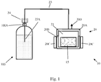
- Reference is made now to
Fig. 1 , which is a schematic illustration of carbonatingsystem 10, according to embodiments of the present invention.System 10 may comprise CO2 production unit 20 which is connected viagas conduit 23 and throughgas disposing plug 24 togas disposing port 23A.Gas production unit 20 may comprise a gasproduction base element 20B, gasproduction cap element 20A, heatenergy supply unit 20C andpressure safety valve 20D.Base element 20B andcap element 20A are designed to form a pressuretight chamber 21 having two outlets. First outlet is the connection togas conduit 23. This outlet is used for providing pressurized CO2 whensystem 10 in use for carbonating. A second outlet is possible viasafety valve 20D, when the pressure insidechamber 21 is higher than a predefined value.Gas conduit 23 may have, close to its distal end,gas disposing plug 24 that may be adapted to tightly and securely attach a container, such asliquid container 100, andgas disposing port 23A adapted to be submerged in the liquid incontainer 100, in order to provide CO2 to it.Chamber 21 is designed to accommodate certain amount of CO2 carrier material, for example in the form of a tablet (or capsule), such as tablet 15.Whenchamber 21 contains CO2 carrier material, such as sodium bicarbonate and is tightly closed, the carrier material may be heated by heatenergy supply unit 20C when energized by electrical energy. When the temperature ofcarrier material 15 reaches decomposition values heatenergy supply unit 20C may be released and when its pressure climbs high enough (higher than the idle pressure inconduit 23 and container 100) CO2 starts flowing intocontainer 100 and carbonation of the liquid incontainer 100 begins. The rate of CO2 production and supply may be controlled, for example, by the control of the temperature of the decomposition. - Reference is made to
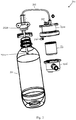
Fig. 2 which is a schematic illustration ofsystem 200 for providing pressurized gas for the production of sparkling drinks according to embodiments of the present invention. According to embodiments of the present invention,system 200 may include high pressure chamber 204 comprising chamber cap element 204A andchamber base element 204B. Pressure chamber 204 is connectable to liquid container (or bottle) 201 through pressure-sealed bottle-feedingpipe 202.Pipe 202 may connect to chamber 204 at one end and to bottle 201, throughpipe outlet 202B, at the other end.Pipe outlet 202B may be inserted to bottle 1, andbottle cap 202A may be assembled ontopipe 202 to enable sealing the connection ofpipe 202 to bottle 201. CO2carrier material unit 205 may be placed in chamber 204 before its cap element 204A andbase element 204B are tightly closed to each other.System 200 may also includeheating device 207 for heating pressure chamber 204 and itscarrier material unit 205 contained in it. When pressure chamber 204 is closed and heated, CO2carrier material unit 205 inside pressure chamber 204 is heated, and CO2 gas is released into pressure chamber 204. The released gas may flow from pressure chamber 204 intobottle 201 throughpipe 202,bottle cap 202A andpipe outlet 202B. When atwork system 200 may be under pressure of 20 - 150 psi, or higher. Hencebottle cap 202A andpipe outlet 202B forming the connection ofsystem 200 to bottle 201 should sustain the pressure levels ofsystem 200 and be pressure-sealed at these pressure levels, and so should be pressure chamber 204,bottle 201, andpipe 202. - As is well known in the art, the boiling point of a substance is the temperature at which the vapor pressure of the liquid equals the pressure surrounding the liquid and the liquid changes into a vapor. Thus, raising the pressure surrounding the liquid will result in raising the temperature in which the fluid reaches the boiling point. That is, a liquid at high surrounding pressure has a higher boiling point than when that liquid is at atmospheric pressure.
- According to some embodiments of the present invention, CO2 carrier material may be placed within CO2
carrier material unit 205 inside pressure chamber 204 and may be wet prior to heating. When heating CO2 carrier material in wet form, the fluid serves as a thermal conductor as long as the fluid that wets the CO2 carrier material remains in a liquid state. Since pressure chamber 204 is pressure sealed, heating of CO2 carrier material in pressure chamber 204 raises the pressure in the chamber 204, and thus raises the temperature in which the fluid in chamber 204 vapors. Thus, the fluid preserves its thermal conducting characteristics at higher temperatures than under atmospheric pressure and thus remains effective as a thermal conductor during the heating process of the CO2 carrier material to temperatures of over 100°C. - According to some embodiments of the present invention,
heating device 207 may be an induction heating device. According to otherembodiments heating device 207 may be a microwave heater. -
System 200 may include atemperature regulator 206 that may include a temperature sensor to measure the temperature inside chamber 204 and provide feedback toheating device 207 so as to regulate the temperature to be, for example, between 150 to 400 degrees Celsius. It would be appreciated that when CO2 carrier material inunit 205 is in a wet form lower temperatures may be required. Furthermore, as noted above, when carrier material is sodium bicarbonate, heating to a temperature of over 200 degrees Celsius is not beneficial. - CO2
carrier material unit 205 may be provided in any suitable form such as powder (either dry or wet), tablet, capsule etc. CO2carrier material unit 205 may be mixed or otherwise provided with various other flavoring materials that may be released as gas and mix with the drink. For example, a tablet may include a layer of sodium bicarbonate and a plurality of layers of additives. - Reference is now made to
Fig. 3 which is a schematic illustration ofsystem 300 for providing gas for the production of sparkling drinks according to embodiments of the present invention.System 300 may be very much similar tosystem 200 ofFig. 2 , however it may further comprise afan 303 to cool the gas flowing inpipe 320 which may be, for example, spiral shaped to enable more efficient cooling of the produced gas. - Reference is made now to
Fig. 4 , which is schematic illustration ofsystem 400 for providing gas for the production of sparkling drinks according to embodiments of the present invention.System 400 may comprise CO2 production unit 20 which is connected viagas conduit 23 and throughgas disposing plug 24 togas disposing port 23A.Gas production unit 20 may comprise a gasproduction base element 20B, gasproduction cap element 20A, heatenergy supply unit 20C andpressure safety valve 20D.Base element 20B andcap element 20A are designed to form a pressuretight chamber 21 having two outlets. First outlet is the connection togas conduit 23. This outlet is used for providing pressurized CO2 whensystem 400 is in use for carbonating. A second outlet is enabled viasafety valve 20D, when the pressure insidechamber 21 is higher than a predefined value.Gas conduit 23 may have, close to its distal end,gas disposing plug 24 that may be adapted to tightly attach a container, such asliquid container 100, andgas disposing port 23A adapted to be submerged in the liquid incontainer 100, in order to provide CO2 to it.Chamber 21 may be designed and may function similarly tochamber 21 described with respect toFig. 1 . - According to one embodiment of the present invention,
gas production unit 20 may further have an inlet (not shown) for introducing fluid from a source (such as liquid container 100), external togas production unit 20, into pressuretight chamber 21, to wet a CO2 carrier material placed withinchamber 21 in solid or dry powder form. It would be appreciated by those skilled in the art that the inlet intochamber 21 may further comprise a unidirectional valve (not shown) to prevent gas produced inchamber 21 to exit through the unidirectional valve. - According to some embodiments, fluid introduced into
chamber 21 may be water. According to other embodiments the fluid introduced intochamber 21 may be water with additives, such as flavor and/or color additives. In yet additional embodiments of the present invention, fluid introduced intochamber 21 may be edible oil and/or aromatic oil. According to other embodiments, the fluid may be an emulsion of water and oil such as aromatic oil. It would be appreciated that other fluids may be used. -
System 400 may further comprise circulation means 40, such as a pump, that is adapted to pump liquid fromcontainer 100 viaconduit 40A, the distal end of which is adapted to be submerged in the liquid incontainer 100 and to return that liquid viaconduit 40B intocontainer 100. According to oneembodiment conduits plug 24, however other embodiments may be utilized. According to another or additional embodiment,conduits conduits conduit 40B that is distal from circulation means 40 may be in a distance fromplug 24 that will ensure that it will remain out of the liquid incontainer 100 whencontainer 100 is substantially in upright position. The liquid that is returned viaconduit 40B may be sprayed into the headspace ofcontainer 100, for example by forming the distal end ofconduit 40B to provide liquid in the form of a spray. Circulation caused by the operation of circulation means 40 may improve (i.e. expend the amount of CO2 gas dissolved in the container) and speed up the dissolving of CO2 in the liquid. The inventor of the invention described in this application has discovered that whensystem 400 is in pressure equilibrium with the pressure insidecontainer 100, after certain amount of gas was dissolved, the activation of circulation means 40 so that carbonated liquid is pumped fromcontainer 100 and sprayed back to its headspace enhances the rate of dissolving the gas in the liquid so that the pressure insidecontainer 100 drops, due to the additional gas that was dissolved in the liquid and therefore the pressure produced by CO2 production unit 20 is now higher than thatinside container 100, and therefore additional amount of gas is provided tocontainer 100. Thus, circulation means 40 may be activated continuously or periodically during the production of gas bygas production unit 20 to enable dissolving of larger amounts of gas in the liquid. An acidity indicator that was placed incontainer 100 indicated repeating raise of acidity of the liquid incontainer 100 as the activation of circulation means continued, which indicates that the amount of CO2 gas incontainer 100 grew with the activation of circulation means 40. It would be appreciated that any other system and method known in the art for dissolving CO2 gas in the liquid incontainer 100 may be used. - Reference is made now to
Fig. 5 , which is schematic illustration ofsystem 500 for providing gas for the production of sparkling drinks according to embodiments of the present invention.Chamber 20,conduit 23, plug 24 andgas disposing port 23A are built and may function very much like their respective elements in the embodiment ofFig. 1 .System 500 may further comprise pressure control unit 30, comprising pressure transmitter/gauge reading 30A,pressure control unit 30B andheat control line 30C. The pressure of the produced gas may be measured in thegas conduit 23 or in similar location. The gas pressure indication may be provided bypressure control unit 30B. Pressure control unit may be acting as a simple ON/OFF unit that may turn off heatenergy supply unit 20C when the measured gas pressure exceeds a first predefined value and resume heating when that pressure falls below a second predefined pressure value. In other embodiments controlunit 30B may perform more complicated control functions, such a combination of one or more of proportional, derivative and integral (PID) of the difference between the measured pressure and a reference value. Other control functions may also be utilized, to achieve faster response, more accurate resulting pressure, and the like. It will be apparent to one skilled in the art that the amount of heat transferred to the active material, such astablet 15 ofFigs. 1 ,4 and5 ortablet 205 ofFigs 2 and3 , has an effect on the total amount and rate of release of produced gas, so that when the amount of heat providedcauses tablet 15 ortablet 205 to reach temperature that is higher than the decomposition temperature gas will begin to release and temperature higher than that will increase the rate of release. - Heat may be transferred to tablets, according to embodiments of the present invention, in one or more from a list various heating methods. Reference is made now to
Figs. 6A and 6B , which are cross section side views of two different forms ofgas production units Figs. 6C, 6D and 6E, 6F which are optional top views of same, according to two embodiments of the present invention.Gas production units respective tablets energy supply unit tablets chamber base unit tablets base unit 520B, 630B is made with heat fins protruding from the bottom towards the inside ofchamber heat fins Figs. 6A, 6B may have the form as depicted inFigs. 6C/6D or Figs. 6E/6F respectively, in which the protruding fins are described by the thick black lines.Tablets respective fins Fig. 4 , according to some embodiments, CO2 carrier material intablets gas production units - Heat may be produced, according to embodiments of the present invention, inside the tablet in the gas production unit, using induction heating mechanism. Reference is made now to
Fig. 7 , which is a cross section view ofgas production unit 720 made across the middle of the gas production unit, according to embodiments of the present invention. In this embodiment heatenergy supply unit 720C ofgas generating unit 720 is formed as an induction AC electromagnetic generator, as is known in the art for induction heating.Tablet 750 includes, spread substantially evenly inside it, iron or ferrous alloys chips. According to some embodiments these chips may be made of other material having high magnetic permeability. When heatenergy supply unit 720C is energized the electromagnetic energy invokes heating of the iron/ferrous chips insidetablet 750, which in turn heats the active material of the tablet. In experiments carried out by the inventor of the current invention it was observed that power supplied to heatenergy supply unit 720C was equal to power supplied to heater working in heat conduction mechanism yet the heating of the tablet having same amount of sodium bicarbonate resulted heating to same temperature within time that was shorter compared with heat conduction mechanism, and the amount of produced CO2 gas was larger compared than the gas produced using heat conduction mechanism. - Tablets made for use with induction heating may comprise certain amount of ferrous chips calculated to provide enough heating within defined period of time. According to another embodiment the heat generating material may be carbon chips. The size, spherical density and the level of unity of dispersion of the chips in the tablet may be selected to achieve the required level of heating and the time required for that heating. According to some embodiments tablets for the production of CO2 gas may further comprise taste additives, flavor additives, color additives, and the like.
- In experiments carried out by the inventor of the present invention he discovered that when heating the tablet using induction mechanism the rate of decomposition of the tablet and the rate of gas production may be kept same as in conduction heating with lower temperatures of the heating chamber.
-
Heating chamber units - Reference is now made to
Figs. 8A and8B , which are flowchart illustrations of methods for providing gas, such as CO2, for the production of, for example, sparkling drinks, according to embodiments of the present invention. In block 810 a system including a pressure chamber and a pressure-sealed bottle-feeding pipe connectable to a bottle is provided. Inblock 820 the bottle is filled with liquid and is attached to the system in a pressure sealed manner. Inblock 830 CO2 carrier such as sodium bicarbonate or other substance that includes carbon dioxide is placed in the pressure chamber. Inblock 840 the pressure chamber is pressure sealed and inblock 850 the pressure chamber is heated. As may be seen inblock 845 inFig. 8B , according to some embodiments of the present invention, after the pressure chamber is pressure sealed, fluid may be introduced into the pressure chamber from an external fluid source, such as from the bottle. The fluid introduced into the chamber, may wet the CO2 carrier in the pressure chamber and may serve as a thermal conductor. Inblock 860 the CO2 gas that is released from the carrier (that is placed in the pressure chamber) flows through the pipe into the bottle. Optionally circulating means may be activated to pump liquid from the container and spray them back to the headspace in the container. The gas is then dissolved in the liquid found in the bottle inblock 870 to create sparkling drink. - According to some embodiments of the method according to the present invention, introducing fluid into the pressure chamber may precede the heating of the CO2 carrier within the pressure chamber.
- While embodiments of the present invention were described with relation to preparation of sparkling drinks, embodiments of the present invention are not limited to this application. Carbonated liquids may be produced according to embodiments of the present invention for any other suitable application in which carbonated liquids are required.
- This disclosure also includes the subject matter of the following clauses:
- 1. A method for producing sparkling drinks, the method comprising:
- providing pressure chamber and a pressure-sealable bottle-feeding pipe connectable to a bottle;
- attaching a bottle filled with liquid to the pressure-sealed bottle-feeding pipe in a pressure sealed manner;
- placing substance that includes carbon dioxide in the chamber;
- pressure sealing the chamber; and
- providing heat to the substrate.
- 2. The method of clause 1 further comprising activating circulating means to pump liquid from said bottle and to spray it back into the bottle.
- 3. The method of clause 2 wherein said providing of heat is done by energizing electrical heater located around said chamber.
- 4. The method of clause 2 wherein said providing of heat is done by providing induction heating energy to said substance.
- 5. A device for providing carbon dioxide gas, the device comprising:
- a pressure-sealed pressure chamber adapted to be filled with substance that includes carbon dioxide;
- a gas conduit connected at its proximal end to said chamber to provide said gas from said chamber; and
- heat energy unit to provide energy to heat said substance in said chamber; wherein said chamber comprising a base element and a cap element, said base element and said cap element are adapted to keep pressure inside said chamber in closed position and to open and allow inserting and removing substance when in opened position.
- 6. The device of clause 5 further comprising container cap disposed so that said conduit passes via said cap in a pressure-sealed manner, said cap is disposed in a distance from the distal end of said conduit so as to ensure that when a container filled with liquid is adapted to and secured said container cap said distal end of said conduit is submerged in said liquid.
- 7. The device of clause 6 further comprising circulating means comprising:
- circulating pump;
- inlet conduit connected to said pump at its inlet port and made to have its free end submerged in said liquid in said container when said container is attached to said device and filled with liquid; and
- outlet conduit connected to said pump at its outlet port and made to spray liquid received from said pump in the headspace of said container.
- 8. The device of clause 6 wherein said base element is formed with heating fins protruding from the inner face of the element.
- 9. The device of clause 6 wherein said heat energy unit comprising one or more electrical heating elements to provide heat to said substance.
- 10. The device of clause 6 wherein said heat energy unit comprising electromagnetic element to provide electromagnetic energy to said substance by induction heating mechanism.
- 11. The device of clause 6 wherein said heat energy unit is a microwave heater..
- 12. The device of clause 6 further comprising pressure control unit comprising;
- heat control unit;
- pressure indicator to provide indication of the pressure in said pressure conduit; and
- temperature control signal provided by said pressure control unit to said heat energy unit, to control said pressure by said heat energy unit.
- 13. The device of clause 6 wherein said gas conduit is shaped as a cooling element, further comprising:
cooling fan adapted to flow air on said cooling element shaped conduit. - 14. The device of clause 5 further comprising a safety pressure outlet to relief pressure from said chamber when said pressure exceeds predefined pressure level;
- 15. Capsule for producing gas in a device for providing carbon dioxide gas, the capsule comprising:
sodium bicarbonate in one of solid, dry powder, wet powder, solution, emulsion and suspension form. - 16. The capsule of
clause 15 further comprising at least one additive form the list comprising: taste additive, flavor additive, color additive. - 17. The capsule of
clause 15 further comprising chips of ferrous material. - 18. The capsule of
clause 15 encapsulated in a thin envelope of non-ferrous material, said envelope having one or more punctures made in its wall to allow releasing of gas produced in the envelope. - 19. The capsule of
clause 15 wherein one face of it is formed with protrusions and recesses to fit onto an inner face of a base element of a pressure chamber made with suitable recesses and protrusions. - 20. The capsule of clause 18 wherein said thin envelope comprises more than one compartment.
- 21. The capsule of
clause 20 wherein at least one of said compartments comprise a carbon dioxide carrier material in a dry form and at least another of said compartments comprise a fluid to wet the dry form carbon dioxide carrier prior to heating. - 22. The capsule of
clause 21 wherein said fluid is one or more of a group consisting of: water, edible oil and aromatic oil.
Claims (4)
- A method for producing sparkling drinks, the method comprising:providing (810) a pressure chamber (21; 204; 304) and a pressure-sealable bottle-feeding pipe (23; 202; 0320) connectable to a bottle or a container;attaching (820) a bottle or a container filled with liquid to the pressure-sealed bottle-feeding pipe in a pressure sealed manner;placing (830)sodium bicarbonate in the pressure chamber;pressure sealing (840) the pressure chamber; andproviding heat (850) to heat the pressure chamber to 150-400 °C to thermally decompose the sodium bicarbonate inside the pressure chamber to release carbon dioxide.
- The method of claim 1 further comprising activating circulating means to pump liquid from said bottle and to spray it back into the bottle.
- The method of claim 2 wherein said providing of heat is done by energizing electrical heater located around said chamber.
- The method of claim 2 wherein said providing of heat is done by providing induction heating energy to said substance.
Applications Claiming Priority (4)
| Application Number | Priority Date | Filing Date | Title |
|---|---|---|---|
| US201261693820P | 2012-08-28 | 2012-08-28 | |
| US13/685,050 US9700852B2 (en) | 2012-08-28 | 2012-11-26 | System, method and capsules for producing sparkling drinks |
| EP13833415.6A EP2890277B1 (en) | 2012-08-28 | 2013-08-18 | System, method and capsules for producing sparkling drinks |
| PCT/IL2013/050699 WO2014033705A2 (en) | 2012-08-28 | 2013-08-18 | System, method and capsules for producing sparkling drinks |
Related Parent Applications (2)
| Application Number | Title | Priority Date | Filing Date |
|---|---|---|---|
| EP13833415.6A Division EP2890277B1 (en) | 2012-08-28 | 2013-08-18 | System, method and capsules for producing sparkling drinks |
| EP13833415.6A Division-Into EP2890277B1 (en) | 2012-08-28 | 2013-08-18 | System, method and capsules for producing sparkling drinks |
Publications (1)
| Publication Number | Publication Date |
|---|---|
| EP3530156A1 true EP3530156A1 (en) | 2019-08-28 |
Family
ID=50184528
Family Applications (2)
| Application Number | Title | Priority Date | Filing Date |
|---|---|---|---|
| EP13833415.6A Active EP2890277B1 (en) | 2012-08-28 | 2013-08-18 | System, method and capsules for producing sparkling drinks |
| EP19162029.3A Withdrawn EP3530156A1 (en) | 2012-08-28 | 2013-08-18 | System, method and capsules for producing sparkling drinks |
Family Applications Before (1)
| Application Number | Title | Priority Date | Filing Date |
|---|---|---|---|
| EP13833415.6A Active EP2890277B1 (en) | 2012-08-28 | 2013-08-18 | System, method and capsules for producing sparkling drinks |
Country Status (22)
| Country | Link |
|---|---|
| US (3) | US9700852B2 (en) |
| EP (2) | EP2890277B1 (en) |
| JP (1) | JP6271552B2 (en) |
| KR (3) | KR102393240B1 (en) |
| CN (3) | CN105431359A (en) |
| AU (2) | AU2013311061B2 (en) |
| BR (1) | BR112015004589B1 (en) |
| CA (3) | CA2882232C (en) |
| CY (1) | CY1121927T1 (en) |
| DK (1) | DK2890277T3 (en) |
| ES (1) | ES2734995T3 (en) |
| HR (1) | HRP20191253T1 (en) |
| HU (1) | HUE044489T2 (en) |
| IL (3) | IL237398B (en) |
| LT (1) | LT2890277T (en) |
| MX (2) | MX368812B (en) |
| PL (1) | PL2890277T3 (en) |
| PT (1) | PT2890277T (en) |
| RS (1) | RS59183B1 (en) |
| RU (1) | RU2633265C2 (en) |
| SI (1) | SI2890277T1 (en) |
| WO (1) | WO2014033705A2 (en) |
Families Citing this family (35)
| Publication number | Priority date | Publication date | Assignee | Title |
|---|---|---|---|---|
| US9198455B2 (en) | 2012-06-29 | 2015-12-01 | Bonne O Inc. | Carbon dioxide source tablet and beverage carbonating system including the same |
| US8985561B2 (en) | 2012-06-29 | 2015-03-24 | Bonne O Inc. | Beverage carbonating system and method for carbonating a beverage |
| US9700852B2 (en) | 2012-08-28 | 2017-07-11 | So Spark Ltd. | System, method and capsules for producing sparkling drinks |
| USD731223S1 (en) | 2013-10-11 | 2015-06-09 | Bonne O Inc. | Beverage carbonation system base |
| EP2865301A1 (en) * | 2013-10-28 | 2015-04-29 | Nestec S.A. | Beverage dispensing system, method for providing a multi-layered beverage, and ingredients container for use thereof |
| US9382119B2 (en) | 2014-01-27 | 2016-07-05 | So Spark Ltd. | Rapid high-pressure microwave thermal decomposition system, capsule and method for using same |
| US10654007B2 (en) * | 2014-06-03 | 2020-05-19 | Robert A. Stevenson | Wine bottle aerator |
| WO2016142139A1 (en) * | 2015-03-12 | 2016-09-15 | BSH Hausgeräte GmbH | Mixed beverage unit |
| US10041863B2 (en) * | 2015-04-03 | 2018-08-07 | Pepsico, Inc. | Method of measuring carbonation levels in open-container beverages |
| US10791752B2 (en) * | 2015-07-22 | 2020-10-06 | Bev-Edge, Llc | Methods and systems for an intelligent beverage mixing appliance |
| KR101830659B1 (en) * | 2015-12-15 | 2018-02-21 | 엘지전자 주식회사 | Apparatus of producing carbonated water |
| KR101830658B1 (en) * | 2015-12-15 | 2018-02-21 | 엘지전자 주식회사 | Apparatus of producing carbonated water |
| US11219873B1 (en) * | 2016-01-22 | 2022-01-11 | Blichmann Engineering, LLC | Carbonation method |
| US10456757B1 (en) * | 2016-01-22 | 2019-10-29 | John Blichmann | In-line carbonation system |
| CA3041722A1 (en) | 2016-11-09 | 2018-05-17 | Pepsico, Inc. | Carbonated beverage makers, methods, and systems |
| US10252900B2 (en) * | 2016-12-07 | 2019-04-09 | Cornelius Beverage Technologies Limited | Apparatuses, systems, and methods for dispensing beverages using alcoholic concentrates |
| CN108158402B (en) * | 2017-12-05 | 2020-09-15 | 杭州易杯食品科技有限公司 | Method for making foaming beverage by capsule beverage machine and capsule beverage machine |
| WO2020084615A1 (en) * | 2018-10-23 | 2020-04-30 | Barak Roi | A set-up for preparing enhanced beverages |
| US11529594B2 (en) | 2018-11-15 | 2022-12-20 | Bonne O Inc. | Beverage carbonation system and beverage carbonator |
| AU2020200706A1 (en) * | 2019-02-04 | 2020-08-20 | Hydrogen4Health Pty Ltd | Hydrogen-based compositions |
| RU2731100C1 (en) * | 2019-04-15 | 2020-08-28 | Общество С Ограниченной Ответственностью "Аквафор" (Ооо "Аквафор") | Liquid supply device |
| CN110255563B (en) * | 2019-07-05 | 2023-10-27 | 上海未几网络科技有限公司 | CO for aquatic weed fish tank 2 Gas generator |
| CN110537743A (en) * | 2019-10-14 | 2019-12-06 | 昆山联滔电子有限公司 | electronic cigarette, seasoning blasting bead applied to electronic cigarette and tobacco filter |
| US11465106B2 (en) | 2020-05-14 | 2022-10-11 | Robert A. Stevenson | Expansion chamber for a wine bottle aerator |
| KR20220076547A (en) * | 2020-11-29 | 2022-06-08 | 주식회사 인더케그 | brewing apparatus |
| CN113724911B (en) * | 2021-08-19 | 2023-11-28 | 深圳市华星光电半导体显示技术有限公司 | Conductive paste, manufacturing method of conductive wire, display panel and spliced screen |
| US11751585B1 (en) | 2022-05-13 | 2023-09-12 | Sharkninja Operating Llc | Flavored beverage carbonation system |
| WO2023216231A1 (en) | 2022-05-13 | 2023-11-16 | Sharkninja Operating Llc | Agitator for a carbonation system |
| US11647860B1 (en) | 2022-05-13 | 2023-05-16 | Sharkninja Operating Llc | Flavored beverage carbonation system |
| US11745996B1 (en) | 2022-11-17 | 2023-09-05 | Sharkninja Operating Llc | Ingredient containers for use with beverage dispensers |
| US11738988B1 (en) | 2022-11-17 | 2023-08-29 | Sharkninja Operating Llc | Ingredient container valve control |
| US11634314B1 (en) | 2022-11-17 | 2023-04-25 | Sharkninja Operating Llc | Dosing accuracy |
| US11871867B1 (en) | 2023-03-22 | 2024-01-16 | Sharkninja Operating Llc | Additive container with bottom cover |
| US11925287B1 (en) | 2023-03-22 | 2024-03-12 | Sharkninja Operating Llc | Additive container with inlet tube |
| US11931704B1 (en) | 2023-06-16 | 2024-03-19 | Sharkninja Operating Llc | Carbonation chamber |
Citations (8)
| Publication number | Priority date | Publication date | Assignee | Title |
|---|---|---|---|---|
| GB323102A (en) | 1928-12-06 | 1929-12-24 | Augustus Pearce Blaxter | Improvements in and connected with carbonating apparatus |
| US4636337A (en) | 1983-06-15 | 1987-01-13 | The Coca-Cola Company | Apparatus for rapid carbonation |
| US5021219A (en) | 1988-12-08 | 1991-06-04 | The Coca-Cola Company | Gas generator for a carbonated drink dispenser |
| US5182084A (en) | 1987-10-15 | 1993-01-26 | The Coca-Cola Co. | Portable automatic water carbonator |
| US5192513A (en) | 1991-07-26 | 1993-03-09 | William C. Stumphauzer | High speed process and apparatus for carbonating water |
| WO1994010860A1 (en) | 1992-11-19 | 1994-05-26 | Stumphauzer William C | Process and apparatus for rapidly carbonating a liquid beverage |
| US5350587A (en) | 1987-10-15 | 1994-09-27 | The Coca-Cola Company | Method of dispensing carbonated beverage using a gas generator |
| WO2011094677A2 (en) | 2010-02-01 | 2011-08-04 | Green Mountain Coffee Roasters, Inc. | Method and apparatus for cartridge-based carbonation of beverages |
Family Cites Families (49)
| Publication number | Priority date | Publication date | Assignee | Title |
|---|---|---|---|---|
| US3855397A (en) * | 1973-04-12 | 1974-12-17 | Allied Chem | Method of producing sodium carbonate and bicarbonate spherules from brine |
| US3891509A (en) | 1974-05-06 | 1975-06-24 | Clinical Convenience Products | CO{HD 2 {B generating tablet for culture devices |
| US4040342A (en) | 1975-10-14 | 1977-08-09 | Robert Roy Austin | Apparatus for generation of carbon dioxide gas and the carbonation of water |
| JPS576285Y2 (en) * | 1979-02-23 | 1982-02-05 | ||
| JPS55122750A (en) | 1979-03-14 | 1980-09-20 | Showa Denko Kk | Production of aminonitrile |
| US4386109A (en) | 1981-02-25 | 1983-05-31 | Raytheon Company | Microwave expresso coffee maker and process |
| US4600123A (en) | 1982-12-16 | 1986-07-15 | Rocket Research Company, A Division Of Rockor, Inc. | Propellant augmented pressurized gas dispensing device |
| JPH01139128A (en) * | 1987-10-15 | 1989-05-31 | Coca Cola Co:The | Portable automatic water carbonator requiring no electric constitutional element |
| CN2030018U (en) * | 1988-05-24 | 1989-01-04 | 柯宏凯 | Foods preservation cabinet by carbon dioxide |
| EP0343673B1 (en) | 1988-05-27 | 1993-11-24 | Ceskoslovenska Akademie Ved | Method of production of extra light soda |
| JPH0686978A (en) | 1992-09-09 | 1994-03-29 | Sanden Corp | Electrolytic ionic water producing apparatus |
| BR9508456A (en) * | 1994-07-29 | 1997-12-23 | Gambro Ab | Process and device for measuring the concentration of urea or a similar substance in a composite solution |
| US6205769B1 (en) | 1995-06-07 | 2001-03-27 | John E. Brandenburg | Compact coupling for microwave-electro-thermal thruster |
| JPH10302141A (en) * | 1997-04-23 | 1998-11-13 | Matsushita Refrig Co Ltd | Drink supply device |
| US5936499A (en) | 1998-02-18 | 1999-08-10 | General Electric Company | Pressure control system for zero boiloff superconducting magnet |
| CN1069959C (en) | 1998-07-27 | 2001-08-22 | 巧星股份有限公司 | Gas filling method |
| WO2000069775A1 (en) * | 1999-05-18 | 2000-11-23 | Southwest Research Institute | Energy-activated compositions for controlled sustained release of a gas |
| JP4482984B2 (en) | 1999-11-15 | 2010-06-16 | シンフォニアテクノロジー株式会社 | Vibrating feeder for powder supply |
| US7922984B2 (en) | 2000-02-18 | 2011-04-12 | Selective Micro Technologies, Llc | Apparatus and method for controlled delivery of a gas |
| US6426111B1 (en) | 2000-06-02 | 2002-07-30 | Gerald Phillip Hirsch | Effervescent mixtures and methods of making |
| US7083071B1 (en) | 2000-06-08 | 2006-08-01 | Beverage Works, Inc. | Drink supply canister for beverage dispensing apparatus |
| US7182970B2 (en) | 2001-12-20 | 2007-02-27 | Lipton, Division Of Conopco, Inc. | Beverage brewing system and method for brewing a beverage |
| JP2004215551A (en) * | 2003-01-14 | 2004-08-05 | Mori Seiyu Kk | Method for lowering alcohol content of ready-made beer |
| CN2645758Y (en) | 2003-10-28 | 2004-10-06 | 申光裕 | Flameproof environment protection type chlorine dioxide generator |
| JP2007513017A (en) * | 2003-11-10 | 2007-05-24 | インフレイト エルエルシー | Method and apparatus for pressurizing a container |
| CN2736303Y (en) * | 2004-07-28 | 2005-10-26 | 刘学凡 | Portable effervescent drinking bottle |
| JP4522207B2 (en) | 2004-09-17 | 2010-08-11 | キヤノン株式会社 | Camera system, camera body and interchangeable lens |
| US7845522B2 (en) | 2005-02-02 | 2010-12-07 | Sturman Bg, Llc | Integrated and disposable dispenser assembly |
| JP2006263253A (en) * | 2005-03-25 | 2006-10-05 | Matsushita Electric Works Ltd | Blood circulation promoting apparatus |
| US8372168B2 (en) | 2005-09-16 | 2013-02-12 | Protonex Technology Corporation | Hydrogen generating fuel cartridge with volume exchange configuration |
| WO2007096877A2 (en) | 2006-02-21 | 2007-08-30 | Rf Dynamics Ltd. | Electromagnetic heating |
| US20090236334A1 (en) | 2006-07-10 | 2009-09-24 | Rf Dynamics Ltd | Food preparation |
| DE102007001609A1 (en) | 2007-01-04 | 2008-07-10 | Spengler Gmbh & Co. Kg | Device for preparing a carbonated mixed drink comprises a mixing chamber with a pressure-tight lid arranged between a feed unit and a release unit |
| US9131543B2 (en) | 2007-08-30 | 2015-09-08 | Goji Limited | Dynamic impedance matching in RF resonator cavity |
| CN101849320B (en) | 2007-09-06 | 2015-12-16 | 德卡产品有限公司 | Rfid system and method |
| BRPI0816730A2 (en) | 2007-09-06 | 2019-09-24 | Deka Products Lp | product distribution system |
| US8592150B2 (en) | 2007-12-05 | 2013-11-26 | Complete Genomics, Inc. | Methods and compositions for long fragment read sequencing |
| EP2255596B1 (en) | 2008-02-21 | 2013-05-08 | Goji Limited | A method and a system for a modular device |
| CN102170955A (en) * | 2008-07-31 | 2011-08-31 | 诺维信公司 | Modular reactor and process for carbon dioxide extraction |
| EP2566297B1 (en) | 2008-11-10 | 2016-04-27 | Goji Limited | Device and method for controlling energy |
| US8376161B2 (en) | 2009-08-08 | 2013-02-19 | Andrew P Golden | Novelty associated with beverages |
| JP5423433B2 (en) | 2010-01-28 | 2014-02-19 | 株式会社島津製作所 | Nuclear medicine diagnostic equipment |
| US9936834B2 (en) | 2010-02-01 | 2018-04-10 | Bedford Systems Llc | Method and apparatus for cartridge-based carbonation of beverages |
| GB2477376B (en) | 2010-12-07 | 2011-12-14 | Clive Roger Stamp | Carbon dioxide production |
| US20140318489A1 (en) | 2011-01-24 | 2014-10-30 | Goji Ltd. | Em energy application for combustion engines |
| WO2013070095A1 (en) | 2011-11-11 | 2013-05-16 | Cquest Technology Limited | Microwave apparatus and methods |
| US8985561B2 (en) | 2012-06-29 | 2015-03-24 | Bonne O Inc. | Beverage carbonating system and method for carbonating a beverage |
| WO2014006510A2 (en) | 2012-07-02 | 2014-01-09 | Goji Ltd. | Rf energy application based on electromagnetic feedback |
| US9700852B2 (en) | 2012-08-28 | 2017-07-11 | So Spark Ltd. | System, method and capsules for producing sparkling drinks |
-
2012
- 2012-11-26 US US13/685,050 patent/US9700852B2/en active Active
-
2013
- 2013-08-18 US US14/423,476 patent/US10213752B2/en active Active
- 2013-08-18 HU HUE13833415 patent/HUE044489T2/en unknown
- 2013-08-18 KR KR1020217042404A patent/KR102393240B1/en active IP Right Grant
- 2013-08-18 RS RSP20190856 patent/RS59183B1/en unknown
- 2013-08-18 CN CN201380045615.XA patent/CN105431359A/en active Pending
- 2013-08-18 KR KR1020207030683A patent/KR102344769B1/en active IP Right Grant
- 2013-08-18 BR BR112015004589-8A patent/BR112015004589B1/en active IP Right Grant
- 2013-08-18 CA CA2882232A patent/CA2882232C/en active Active
- 2013-08-18 ES ES13833415T patent/ES2734995T3/en active Active
- 2013-08-18 PL PL13833415T patent/PL2890277T3/en unknown
- 2013-08-18 RU RU2015107427A patent/RU2633265C2/en active
- 2013-08-18 WO PCT/IL2013/050699 patent/WO2014033705A2/en active Application Filing
- 2013-08-18 MX MX2015002661A patent/MX368812B/en active IP Right Grant
- 2013-08-18 AU AU2013311061A patent/AU2013311061B2/en not_active Ceased
- 2013-08-18 CN CN202011043106.1A patent/CN112155145A/en active Pending
- 2013-08-18 CA CA3144743A patent/CA3144743A1/en active Pending
- 2013-08-18 JP JP2015529205A patent/JP6271552B2/en active Active
- 2013-08-18 CA CA3080765A patent/CA3080765C/en active Active
- 2013-08-18 SI SI201331500T patent/SI2890277T1/en unknown
- 2013-08-18 KR KR1020157006650A patent/KR102171841B1/en active Application Filing
- 2013-08-18 LT LTEP13833415.6T patent/LT2890277T/en unknown
- 2013-08-18 PT PT13833415T patent/PT2890277T/en unknown
- 2013-08-18 EP EP13833415.6A patent/EP2890277B1/en active Active
- 2013-08-18 EP EP19162029.3A patent/EP3530156A1/en not_active Withdrawn
- 2013-08-18 CN CN202011043091.9A patent/CN112167498A/en active Pending
- 2013-08-18 DK DK13833415.6T patent/DK2890277T3/en active
-
2015
- 2015-02-24 IL IL237398A patent/IL237398B/en active IP Right Grant
- 2015-02-27 MX MX2019009056A patent/MX2019009056A/en unknown
-
2017
- 2017-07-25 US US15/658,436 patent/US10143977B2/en active Active
- 2017-12-12 AU AU2017276194A patent/AU2017276194B2/en not_active Ceased
-
2018
- 2018-09-27 IL IL261991A patent/IL261991B/en active IP Right Grant
- 2018-09-27 IL IL261990A patent/IL261990B/en active IP Right Grant
-
2019
- 2019-07-11 CY CY20191100743T patent/CY1121927T1/en unknown
- 2019-07-12 HR HRP20191253TT patent/HRP20191253T1/en unknown
Patent Citations (9)
| Publication number | Priority date | Publication date | Assignee | Title |
|---|---|---|---|---|
| GB323102A (en) | 1928-12-06 | 1929-12-24 | Augustus Pearce Blaxter | Improvements in and connected with carbonating apparatus |
| US4636337A (en) | 1983-06-15 | 1987-01-13 | The Coca-Cola Company | Apparatus for rapid carbonation |
| US5182084A (en) | 1987-10-15 | 1993-01-26 | The Coca-Cola Co. | Portable automatic water carbonator |
| US5350587A (en) | 1987-10-15 | 1994-09-27 | The Coca-Cola Company | Method of dispensing carbonated beverage using a gas generator |
| US5021219A (en) | 1988-12-08 | 1991-06-04 | The Coca-Cola Company | Gas generator for a carbonated drink dispenser |
| US5192513A (en) | 1991-07-26 | 1993-03-09 | William C. Stumphauzer | High speed process and apparatus for carbonating water |
| WO1994010860A1 (en) | 1992-11-19 | 1994-05-26 | Stumphauzer William C | Process and apparatus for rapidly carbonating a liquid beverage |
| WO2011094677A2 (en) | 2010-02-01 | 2011-08-04 | Green Mountain Coffee Roasters, Inc. | Method and apparatus for cartridge-based carbonation of beverages |
| US20110226343A1 (en) | 2010-02-01 | 2011-09-22 | Green Mountain Coffee Roasters, Inc. | Method and apparatus for cartridge-based carbonation of beverages |
Also Published As
Similar Documents
| Publication | Publication Date | Title |
|---|---|---|
| AU2017276194B2 (en) | System, method and capsules for producing sparkling drinks | |
| US4040342A (en) | Apparatus for generation of carbon dioxide gas and the carbonation of water | |
| CN109922668A (en) | Soda draft machine, method and system | |
| CN105011764A (en) | Method and apparatus for cartridge-based carbonation of beverages | |
| US20110271692A1 (en) | System and method for providing a self cooling container | |
| EP2196752A1 (en) | A self cooling container | |
| CN102947655B (en) | Self cooling container and cooling device | |
| JP2008246333A (en) | Measuring method for gas hydrate concentration and measuring device used for the same, and control method for gas hydrate generation device using measuring method and control device using the same | |
| Meleshkin | Effect of SDS concentration on the process of hydrate formation by explosive boiling of liquefied freon 134a in water with SDS volume | |
| KR20100044415A (en) | Heat-insulation and cold-insulation apparatus | |
| Elliott et al. | Apparatus and method for gelling liquefied gasses |
Legal Events
| Date | Code | Title | Description |
|---|---|---|---|
| PUAI | Public reference made under article 153(3) epc to a published international application that has entered the european phase |
Free format text: ORIGINAL CODE: 0009012 |
|
| STAA | Information on the status of an ep patent application or granted ep patent |
Free format text: STATUS: THE APPLICATION HAS BEEN PUBLISHED |
|
| AC | Divisional application: reference to earlier application |
Ref document number: 2890277 Country of ref document: EP Kind code of ref document: P |
|
| AK | Designated contracting states |
Kind code of ref document: A1 Designated state(s): AL AT BE BG CH CY CZ DE DK EE ES FI FR GB GR HR HU IE IS IT LI LT LU LV MC MK MT NL NO PL PT RO RS SE SI SK SM TR |
|
| STAA | Information on the status of an ep patent application or granted ep patent |
Free format text: STATUS: REQUEST FOR EXAMINATION WAS MADE |
|
| 17P | Request for examination filed |
Effective date: 20190909 |
|
| RBV | Designated contracting states (corrected) |
Designated state(s): AL AT BE BG CH CY CZ DE DK EE ES FI FR GB GR HR HU IE IS IT LI LT LU LV MC MK MT NL NO PL PT RO RS SE SI SK SM TR |
|
| REG | Reference to a national code |
Ref country code: DE Ref legal event code: R079 Free format text: PREVIOUS MAIN CLASS: A47J0031440000 Ipc: A23L0002540000 |
|
| GRAP | Despatch of communication of intention to grant a patent |
Free format text: ORIGINAL CODE: EPIDOSNIGR1 |
|
| STAA | Information on the status of an ep patent application or granted ep patent |
Free format text: STATUS: GRANT OF PATENT IS INTENDED |
|
| RIC1 | Information provided on ipc code assigned before grant |
Ipc: B01F 101/14 20220101ALI20230203BHEP Ipc: B01F 23/237 20220101ALI20230203BHEP Ipc: A47J 31/40 20060101ALI20230203BHEP Ipc: A23L 2/54 20060101AFI20230203BHEP |
|
| INTG | Intention to grant announced |
Effective date: 20230220 |
|
| STAA | Information on the status of an ep patent application or granted ep patent |
Free format text: STATUS: THE APPLICATION IS DEEMED TO BE WITHDRAWN |
|
| 18D | Application deemed to be withdrawn |
Effective date: 20230704 |