EP3528759B1 - Composant de fixation pour outils d'insertion pour implants cochléaires minimalement invasifs - Google Patents
Composant de fixation pour outils d'insertion pour implants cochléaires minimalement invasifs Download PDFInfo
- Publication number
- EP3528759B1 EP3528759B1 EP17865697.1A EP17865697A EP3528759B1 EP 3528759 B1 EP3528759 B1 EP 3528759B1 EP 17865697 A EP17865697 A EP 17865697A EP 3528759 B1 EP3528759 B1 EP 3528759B1
- Authority
- EP
- European Patent Office
- Prior art keywords
- retraction
- electrode
- opening
- cochlear
- limiter
- Prior art date
- Legal status (The legal status is an assumption and is not a legal conclusion. Google has not performed a legal analysis and makes no representation as to the accuracy of the status listed.)
- Active
Links
- 238000003780 insertion Methods 0.000 title claims description 88
- 230000037431 insertion Effects 0.000 title claims description 88
- 239000007943 implant Substances 0.000 title claims description 27
- 210000003477 cochlea Anatomy 0.000 claims description 53
- 210000001595 mastoid Anatomy 0.000 claims description 37
- 210000000959 ear middle Anatomy 0.000 claims description 29
- 230000000638 stimulation Effects 0.000 claims description 24
- 230000007246 mechanism Effects 0.000 claims description 11
- 230000001537 neural effect Effects 0.000 claims description 7
- 210000001519 tissue Anatomy 0.000 claims description 7
- 238000000034 method Methods 0.000 description 13
- 239000000463 material Substances 0.000 description 6
- 210000000988 bone and bone Anatomy 0.000 description 5
- 230000004044 response Effects 0.000 description 5
- 238000002513 implantation Methods 0.000 description 4
- 238000012545 processing Methods 0.000 description 4
- 238000001356 surgical procedure Methods 0.000 description 4
- 210000000860 cochlear nerve Anatomy 0.000 description 3
- 239000012530 fluid Substances 0.000 description 3
- 230000008569 process Effects 0.000 description 3
- 238000013459 approach Methods 0.000 description 2
- 210000004556 brain Anatomy 0.000 description 2
- 210000000256 facial nerve Anatomy 0.000 description 2
- 210000001079 scala tympani Anatomy 0.000 description 2
- 210000003454 tympanic membrane Anatomy 0.000 description 2
- 206010002091 Anaesthesia Diseases 0.000 description 1
- 208000037408 Device failure Diseases 0.000 description 1
- 208000004929 Facial Paralysis Diseases 0.000 description 1
- 241000122159 Modiolus Species 0.000 description 1
- 208000028389 Nerve injury Diseases 0.000 description 1
- 208000036826 VIIth nerve paralysis Diseases 0.000 description 1
- 208000027418 Wounds and injury Diseases 0.000 description 1
- 230000036982 action potential Effects 0.000 description 1
- 230000037005 anaesthesia Effects 0.000 description 1
- 210000003484 anatomy Anatomy 0.000 description 1
- 238000003491 array Methods 0.000 description 1
- 230000009286 beneficial effect Effects 0.000 description 1
- 230000005540 biological transmission Effects 0.000 description 1
- 230000015572 biosynthetic process Effects 0.000 description 1
- 230000000903 blocking effect Effects 0.000 description 1
- 210000004027 cell Anatomy 0.000 description 1
- 210000000262 cochlear duct Anatomy 0.000 description 1
- 238000012937 correction Methods 0.000 description 1
- 210000000883 ear external Anatomy 0.000 description 1
- 230000001815 facial effect Effects 0.000 description 1
- 210000003195 fascia Anatomy 0.000 description 1
- 230000006870 function Effects 0.000 description 1
- 208000016354 hearing loss disease Diseases 0.000 description 1
- 230000001771 impaired effect Effects 0.000 description 1
- 238000000338 in vitro Methods 0.000 description 1
- 230000003447 ipsilateral effect Effects 0.000 description 1
- 239000007788 liquid Substances 0.000 description 1
- 230000005012 migration Effects 0.000 description 1
- 238000013508 migration Methods 0.000 description 1
- 230000008764 nerve damage Effects 0.000 description 1
- 230000008058 pain sensation Effects 0.000 description 1
- 210000004049 perilymph Anatomy 0.000 description 1
- 239000002861 polymer material Substances 0.000 description 1
- 229920001296 polysiloxane Polymers 0.000 description 1
- 230000009467 reduction Effects 0.000 description 1
- 238000011160 research Methods 0.000 description 1
- 210000001605 scala vestibuli Anatomy 0.000 description 1
- 230000035807 sensation Effects 0.000 description 1
- 210000003625 skull Anatomy 0.000 description 1
- 230000005236 sound signal Effects 0.000 description 1
- 210000001323 spiral ganglion Anatomy 0.000 description 1
- 230000004936 stimulating effect Effects 0.000 description 1
- 239000000758 substrate Substances 0.000 description 1
- 230000000007 visual effect Effects 0.000 description 1
Images


Classifications
-
- A—HUMAN NECESSITIES
- A61—MEDICAL OR VETERINARY SCIENCE; HYGIENE
- A61N—ELECTROTHERAPY; MAGNETOTHERAPY; RADIATION THERAPY; ULTRASOUND THERAPY
- A61N1/00—Electrotherapy; Circuits therefor
- A61N1/02—Details
- A61N1/04—Electrodes
- A61N1/05—Electrodes for implantation or insertion into the body, e.g. heart electrode
- A61N1/0526—Head electrodes
- A61N1/0541—Cochlear electrodes
-
- A—HUMAN NECESSITIES
- A61—MEDICAL OR VETERINARY SCIENCE; HYGIENE
- A61N—ELECTROTHERAPY; MAGNETOTHERAPY; RADIATION THERAPY; ULTRASOUND THERAPY
- A61N1/00—Electrotherapy; Circuits therefor
- A61N1/18—Applying electric currents by contact electrodes
- A61N1/32—Applying electric currents by contact electrodes alternating or intermittent currents
- A61N1/36—Applying electric currents by contact electrodes alternating or intermittent currents for stimulation
- A61N1/36036—Applying electric currents by contact electrodes alternating or intermittent currents for stimulation of the outer, middle or inner ear
- A61N1/36038—Cochlear stimulation
-
- A—HUMAN NECESSITIES
- A61—MEDICAL OR VETERINARY SCIENCE; HYGIENE
- A61B—DIAGNOSIS; SURGERY; IDENTIFICATION
- A61B17/00—Surgical instruments, devices or methods, e.g. tourniquets
- A61B17/34—Trocars; Puncturing needles
- A61B17/3468—Trocars; Puncturing needles for implanting or removing devices, e.g. prostheses, implants, seeds, wires
-
- A—HUMAN NECESSITIES
- A61—MEDICAL OR VETERINARY SCIENCE; HYGIENE
- A61N—ELECTROTHERAPY; MAGNETOTHERAPY; RADIATION THERAPY; ULTRASOUND THERAPY
- A61N1/00—Electrotherapy; Circuits therefor
- A61N1/18—Applying electric currents by contact electrodes
- A61N1/32—Applying electric currents by contact electrodes alternating or intermittent currents
- A61N1/36—Applying electric currents by contact electrodes alternating or intermittent currents for stimulation
- A61N1/372—Arrangements in connection with the implantation of stimulators
- A61N1/375—Constructional arrangements, e.g. casings
- A61N1/3752—Details of casing-lead connections
Definitions
- the present invention relates to medical implants, and more specifically to an implantable electrode arrangement for cochlear implant systems.
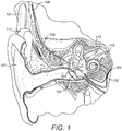
- a normal ear transmits sounds as shown in Figure 1 through the outer ear 101 to the tympanic membrane (eardrum) 102, which moves the bones of the middle ear 103, which in turn vibrate the oval window and round window openings of the cochlea 104.
- the cochlea 104 is a long narrow duct wound spirally about its axis for approximately two and a half turns.
- the cochlea 104 includes an upper channel known as the scala vestibuli and a lower channel known as the scala tympani, which are connected by the cochlear duct.
- the scala tympani forms an upright spiraling cone with a center called the modiolus where the spiral ganglion cells of the acoustic nerve 113 reside.
- the fluid filled cochlea 104 functions as a transducer to generate electric pulses that are transmitted to the cochlear nerve 113, and ultimately to the brain. Hearing is impaired when there are problems in the ability to transduce external sounds into meaningful action potentials along the neural substrate of the cochlea 104.
- hearing impairment can be addressed by an auditory prosthesis system such as a cochlear implant that electrically stimulates auditory nerve tissue with small currents delivered by multiple stimulation contacts distributed along an implant electrode.
- Figure 1 shows some components of a typical cochlear implant system where an external microphone provides an audio signal input to an external signal processing stage 111 which implements one of various known signal processing schemes. The processed signal is converted by the external signal processing stage 111 into a digital data format, such as a sequence of data frames, for transmission into a receiver processor in an implant housing 108.
- the receiver processor in the implant housing 108 may perform additional signal processing such as error correction, pulse formation, etc., and produces a stimulation pattern (based on the extracted audio information) that is sent through an electrode lead 109 to an implanted electrode array 110 which penetrates into the cochlea 104 through a surgical opening in the outer surface of the cochlea 104.
- this electrode array 110 includes multiple stimulation contacts 112 on its surface that deliver the stimulation signals to adjacent neural tissue of the cochlea 104 which the brain of the patient interprets as sound.
- the individual stimulation contacts 112 may be activated sequentially or simultaneously in one or more contact groups.
- Cochlear implantation is a major surgery that involves full anesthesia and usually takes from 1.5 to 5 hours. A significant portion of that time is required for the labor intensive mastoidectomy in which the surgeon creates an opening in the outer mastoid bone of the skull and a bore path through that bone and the middle ear to gain access to the cochlea prior to implantation. During this process, the surgeon needs to carefully mill down through the mastoid bone to the cochlea starting right behind the ipsilateral ear, and using anatomical landmarks to find his way. One of these landmarks is the facial nerve which, if damaged or cut, may cause facial paralysis of the patient.
- FIG 2A shows structural details of a cochlear implant electrode arrangement at the electrode opening 201 into the implanted cochlea 104.
- the electrode array 110 in this example tends to lie toward the outer lateral wall of the spiral-shaped cochlea 104. Over time, there can be a tendency for the electrode array to spring back and retract back out through the electrode opening 201, as shown in Figure 2B .
- the degree of spring back varies depending among other factors on how deeply the electrode array 110 is inserted into the cochlea 104, how well the electrode opening 201 is packed with fascia material, and the specific geometry at the electrode opening 201.
- Such post-surgical electrode retraction pulls the nearest stimulation contact 112 away from its intended target neural tissue within the cochlea 104 back toward the electrode opening 201, or even further, back outside the cochlea 104 into the middle ear 104.
- This can produce pain sensation in the patient when that stimulation contact 112 is energized.
- that stimulation contact 112 will be inactivated and fewer stimulation contacts 112 remain for use to produce sound sensation.
- revision surgery may be required, see for example Connell, S.S., Balkany, T.J., Hodges, A.V., Telischi, F.F., Angeli, S.I., Eshraghi, A.A. in "Electrode migration after cochlear Implantation” published in Otology & Neurotology, 2008 No. 29: 156-159 .
- a cork-shaped stopper has been used to tightly wedge the electrode lead in the electrode opening.
- An anti-retraction skirt has been implemented on the electrode array at the electrode opening which is made of polymer material that swells when contacted by the liquid preilymph medium, thereby holding the electrode array in place.
- Some electrode arrays have a permanent pre-curved shape that does not relax or spring back after insertion into the cochlea.
- Other electrode arrangements contain an internal malleable material on either side of the electrode opening which maintains a bent shape after full insertion of the electrode array to resist retraction.
- US2015/0224300 discloses an implantable electrode arrangement for a cochlear implant system that prevents post-surgical retraction of the electrode.
- the arrangement includes at least one retraction limiter having an extracochlear portion located at a distal end of the extracochlear electrode lead and an intracochlear portion located at a proximal end of the intracochlear electrode array and made at least in part of a swellable material that expands in response to fluid contact.
- the intracochlear portion of the retraction limiter is adapted for deformation away from an outer surface of the array proximal end in response to exposure of the swellable material to perilymph fluid within the cochlea after surgical insertion of the electrode array into the implanted cochlea so as to form an anti-retraction projection preventing post-surgical retraction of the array proximal end back through the electrode opening in the outer surface of the implanted cochlea.
- US2011/0319974 discloses insertion tools, systems, and methods for inserting an electrode array portion of a lead into a bodily orifice are described herein.
- One such insertion tool includes a handle assembly, a retractor assembly disposed at least partially within the handle assembly, and a slider assembly disposed at least partially within the handle assembly.
- the retractor assembly may include a stiffening member configured to be inserted into an electrode array portion and a spring-loaded retractor member coupled to the stiffening member and configured to move from a distal position to a proximal position to at least partially retract the stiffening member from the electrode array portion.
- the slider assembly may be configured to selectively retain the spring-loaded retractor member and further configured to release the spring-loaded retractor member to move from the distal position to the proximal position in response to actuation by a user of the slider assembly.
- WO2011/005993(A1 ) discloses an insertion tool configured to facilitate insertion of a lead into a bodily orifice, which includes a handle assembly configured to facilitate handling of the insertion tool, an insertion assembly coupled to the handle assembly and comprising a rigid holding tube configured to removably couple to a portion of the lead, and a release assembly disposed at least partially within the handle assembly and comprising a release button.
- the release assembly is configured to release the lead from the holding tube in response to user actuation of the release button.
- WO2017/011639(A1 ) discloses a cochlear implant electrode arrangement that prevents post-surgical retraction of the electrode array from the cochlea.
- the arrangement includes an electrode lead that carries cochlear stimulation signals from an implanted signal processor, through an oval shaped posterior tympanotomy opening in the facial recess of a patient, to an electrode array implanted in a cochlea of the patient.
- a retraction limiter slides over the electrode lead through the posterior tympanotomy with projection arms aligned along the long diameter of the posterior tympanotomy, then is rotated to align the projection arms along the short diameter of the posterior tympanotomy, and secured to the electrode lead so that the projection arms prevent post-surgical retraction of the electrode lead back through the posterior tympanotomy.
- US2008/234793(A1 ) discloses an apparatus and method for implanting and securing an implanted medical device in a recipient.
- the implantable medical device includes an electrode assembly that comprises an elongate carrier member having at least one stimulating electrode positioned thereon.
- the carrier member further has a fixation structure positioned thereon configured to interact with a portion of the rigid structure to longitudinally secure the carrier member in the recipient.
- WO2015/085135(A1 ) discloses an electrode for use with a cochlear implant system includes an electrode array with at least one electrode contact, and an electrode lead adjacent to the electrode array.
- the electrode lead has a flexible region configured to allow the electrode lead to bend and has an attachment mechanism with an internal portion positioned within the electrode lead and an external portion configured to be bent and secured to bone.
- a method of securing the electrode to bone is also disclosed.
- US2015/119791(A1 ) discloses a cochlear implant electrode which includes an electrode carrier having an electrode array with a groove disposed in a longitudinal direction along the electrode carrier, and a stopper positioned around the electrode carrier.
- the stopper has a protrusion on its inner surface that is configured to be positioned within the groove such that the stopper is movable with respect to the electrode carrier and a skirt disposed on a portion of its outer surface.
- Another configuration includes an electrode carrier having an electrode array with grooves disposed in a transverse direction along the electrode carrier, and a stopper positioned around the electrode carrier and configured to be positioned within each groove and movable with respect to the electrode carrier.
- the stopper has a skirt disposed on a portion of its outer surface.
- the present invention seeks to provide an implantable electrode arrangement for a cochlear implant system that prevents post-surgical retraction, and is set out in claim 1.
- An extracochlear electrode lead is configured for carrying one or more cochlear stimulation signals from a proximal end of the electrode lead at a mastoid opening in a patient mastoid bone into the middle ear to a distal end of the electrode lead at a cochlear opening in the outer surface of a patient cochlea.
- An intracochlear electrode array is configured for insertion through the cochlear opening into the patient cochlea.
- the electrode array has a proximal end connected to the distal end of the electrode lead, and an outer surface with stimulation contacts configured for applying the cochlear stimulation signals to target neural tissue within the patient cochlea.
- An insertion mechanism includes a retraction limiter configured to fit around and securely engage a portion of the distal end of the electrode lead.
- the retraction limiter has flexible retraction limiting projections longitudinally distributed along its outer surface between the proximal end of the retraction limiter and the distal end of the retraction limiter.
- An insertion tube is configured to fit around the electrode array and the retraction limiter and engages against the outer surface of the patient cochlea at the cochlear opening.
- An insertion plunger is configured to fit within the insertion tube and engage against the proximal end of the retraction limiter.
- the insertion mechanism is operable for the insertion plunger to slide within the insertion tube to push against the proximal end of the retraction limiter to push the electrode array through the cochlear opening into the patient cochlea, and at least a portion of the retraction limiter through the mastoid opening into the middle ear so that when the insertion tube is withdrawn back through the mastoid opening, one or more of the retraction limiting projections enters into the middle ear and displaces out away from the outer surface of the retraction limiter and blocks the mastoid opening so as to prevent retraction of the electrode lead back out from the middle ear.
- the retraction limiter may comprise multiple compressible elliptical segments configured to be compressed radially inward to fit within the insertion tube, and configured to expand radially outward when the insertion tube is withdrawn back through the mastoid opening to form the retraction limiting projections.
- the retracting limiting projections may be opposing pairs of flexible flaps.
- a method of implanting an electrode array in a patient cochlea which does not form part of the present invention, is also described herein to assist with a fuller understanding of the invention.
- a bore hole is prepared including a mastoid opening through a patient mastoid bone into the middle ear and a cochlear opening through an outer surface of a patient cochlea into the cochlea.
- a retraction limiter is securely fit around a distal end of an electrode lead that is configured for carrying one or more cochlear stimulation signals.
- the retraction limiter has a proximal end, a distal end, an outer surface, and a plurality of flexible retraction limiting projections longitudinally distributed along the outer surface of the retraction limiter between the proximal end of the retraction limiter and the distal end of the retraction limiter.
- An insertion tube is fit around the retraction limiter and an electrode array that has a proximal end connected to the distal end of the electrode lead and an outer surface with a plurality of stimulation contacts configured for applying the cochlear stimulation signals to target neural tissue within an implanted patient cochlea.
- An insertion plunger is fit within the insertion tube in engagement with the proximal end of the retraction limiter.
- the insertion tube is fit through the mastoid opening into the bore hole to engage against the outer surface of the patient cochlea at the cochlear opening.
- the insertion plunger slides within the insertion tube to push against the proximal end of the retraction limiter to push the electrode array through the cochlear opening into the patient cochlea, and at least a portion of the retraction limiter through the mastoid opening into the middle ear so that when the insertion tube is withdrawn back through the mastoid opening, one or more of the retraction limiting projections enters into the middle ear and displaces out away from the outer surface of the retraction limiter and blocks the mastoid opening so as to prevent retraction of the electrode lead back out from the middle ear.
- the method may also include withdrawing and removing the insertion plunger from the insertion tube, disengaging the insertion tube from the outer surface of the patient cochlea, and withdrawing the insertion tube from the bore hole via the mastoid opening.
- the retraction limiter may include a plurality of compressible elliptical segments configured to be compressed radially inward to fit within the insertion tube, and configured to expand radially outward when the insertion tube is withdrawn back through the mastoid opening to form the retraction limiting projections.
- the retracting limiting projections may be opposing pairs of flexible flaps.
- Embodiments of the present invention also include a cochlear implant system having an electrode arrangement according to any of the foregoing.
- Embodiments of the present invention are directed to a cochlear implant electrode insertion arrangement that resists post-surgical retraction of the inserted electrode back out of the electrode opening.
- the insertion of the electrode array via the bore hole path is performed with specially designed insertion tools that include an insertion tube for guiding the positioning of the electrode array in front of the cochlear array opening and an insertion plunger to push the array out of the insertion tube into the cochlea.
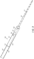
- FIG. 3 shows structural details of a portion of an electrode array insertion arrangement with a retraction limiter according to an embodiment of the present invention.
- An extracochlear electrode lead 109 is configured for carrying one or more cochlear stimulation signals from a proximal end of the electrode lead at a mastoid opening in a patient mastoid bone into the middle ear to a distal end of the electrode lead at a cochlear opening in the outer surface of a patient cochlea 104.
- An intracochlear electrode array 110 is configured for insertion through the cochlear opening into the patient cochlea 104.
- the electrode array 110 has a proximal end 303 connected to the distal end of the electrode lead 109, and an outer surface with stimulation contacts 112 configured for applying the cochlear stimulation signals to target neural tissue within the patient cochlea 104.
- An insertion mechanism 300 includes a retraction limiter 301 configured to fit around and securely engage a portion of the distal end of the electrode lead 109.
- the retraction limiter 301 has flexible retraction limiting projections 305 longitudinally distributed along its outer surface between the proximal end 304 of the retraction limiter 301 and the distal end 302 of the retraction limiter 301.
- An insertion tube 306 is configured to fit around the electrode array 110 and the retraction limiter 301 and engages against the outer surface of the patient cochlea 104 at the cochlear opening.
- An insertion plunger 307 is configured to fit within the insertion tube 306 and engage against the proximal end 304 of the retraction limiter 301 rather than directly pushing against the electrode array 110.
- the insertion mechanism 300 is operable for the insertion plunger 307 to slide within the insertion tube 306 to push against the proximal end 304 of the retraction limiter 301 to push the electrode array 110 through the cochlear opening into the patient cochlea 104, and in one embodiment at least a portion of the retraction limiter 301 through the bore hole toward or into the middle ear 103 so that when the insertion tube 306 is withdrawn back through the mastoid opening, one or more of the retraction limiting projections 305 enters into the bore hole or middle ear 103 and displaces out away from the outer surface of the retraction limiter 301 to block the mastoid opening so as to prevent retraction of the electrode lead 109 back out from the middle ear 103.
- Figure 4A and 4B show structural details of the retraction limiter 301 of Figure 3 .
- Fig. 4A shows an embodiment of a retraction limiter 301 where the retracting limiting projections 305 form opposing pairs of flexible flaps.
- the limiting projections 305 may be equally distributed about the outer surface of the retraction limiter 301 and the number of flexible flaps may vary as well.
- Figure 4B shows another embodiment where the retraction limiter 301 is formed of multiple compressible elliptical segments configured to be compressed radially inward to fit within the insertion tube, and configured to expand radially outward when the insertion tube is withdrawn back through the mastoid opening to form the retraction limiting projections 305.
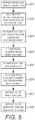
- FIG. 5 shows various logical steps in a method of surgically inserting a cochlear implant electrode array 110 and Figures 6A-6D show structural details of the surgical insertion process for a cochlear implant electrode array 110 .
- a bore hole through the middle ear is prepared, step 501, including a mastoid opening 601 through a patient mastoid bone into the middle ear and a cochlear opening 602 through an outer surface of a patient cochlea into the cochlea 104.
- a retraction limiter 301 structured as described above is securely fit around a distal end of an electrode lead 109 that is configured for carrying one or more cochlear stimulation signals, step 502.
- An insertion tube 306 is fit around the retraction limiter 301 and an electrode array 110 at the distal end of the electrode lead 109, step 503.
- An insertion plunger 307 is fit within the insertion tube 306 in engagement with the proximal end of the retraction limiter 301, step 504.
- the insertion tube 306 is fit through the mastoid opening 601 into the bore hole, step 505, to engage against the outer surface of the patient cochlea 104 at the cochlear opening 602.
- the insertion plunger 307 slides within the insertion tube 306 to push against the proximal end of the retraction limiter 301 to push the electrode array 110 through the cochlear opening 602 into the patient cochlea 104, step 506 as shown in Figure 6B .
- the insertion tube 306 is pulled back with the insertion plunger 307 kept in place to avoid slide-back of the electrode array 110 during retraction of the insertion tube 306.
- At least a portion of the retraction limiter 301 extends through the bore hole and may in a further embodiment extend through the mastoid opening 601 into the middle ear 103 so that when the insertion tube 306 is withdrawn back through the mastoid opening 601, as shown in Figure 6C , step 507, one or more of the retraction limiting projections 305 displaces out away from the outer surface of the retraction limiter 301 and blocks the mastoid opening 601 and engages with the bone in the bore hole, and if extended through the mastoid opening 601, enters into the middle ear 103 so as to prevent retraction of the electrode lead 109 back out from the middle ear 103.
- step 508 as shown in Figure 6D , the insertion tube 306 and the insertion plunger 307 are jointly retracted out through the bore hole. Because the limiting projections 305 of retraction limiter already securely fix the electrode array 110, array retraction in this last surgical step is effectively avoided.
Landscapes
- Health & Medical Sciences (AREA)
- Otolaryngology (AREA)
- Animal Behavior & Ethology (AREA)
- Engineering & Computer Science (AREA)
- Biomedical Technology (AREA)
- Nuclear Medicine, Radiotherapy & Molecular Imaging (AREA)
- Radiology & Medical Imaging (AREA)
- Life Sciences & Earth Sciences (AREA)
- General Health & Medical Sciences (AREA)
- Public Health (AREA)
- Veterinary Medicine (AREA)
- Heart & Thoracic Surgery (AREA)
- Cardiology (AREA)
- Prostheses (AREA)
- Electrotherapy Devices (AREA)
Claims (5)
- Ensemble d'électrodes implantable destiné à un système d'implant cochléaire et comprenant :un conducteur d'électrode extra-cochléaire (109) conçu pour porter un ou plusieurs signaux de stimulation cochléaire provenant d'une extrémité proximale du conducteur d'électrode (109) situé au niveau d'une ouverture mastoïde (601) de l'os mastoïde d'un patient donnant dans l'oreille moyenne (103) vers une extrémité distale du conducteur d'électrode (109) au niveau d'une ouverture cochléaire (602) de la surface extérieure de la cochlée (104) d'un patient ;un réseau d'électrodes intra-cochléaires (110) conçu pour être inséré par l'ouverture cochléaire (602) dans la cochlée (104) du patient, le réseau d'électrodes (110) comportant une extrémité proximale (303) reliée à l'extrémité distale du conducteur d'électrode (109), et une surface extérieure comportant une pluralité de contacts de stimulation (112) conçus pour appliquer les signaux de stimulation cochléaire au tissu neural cible dans la cochlée (104) du patient ; etun mécanisme d'insertion (300) comprenant :i. un limiteur de rétraction (301) conçu pour s'ajuster autour d'une partie, et pour s'engager de manière sûre dans celle-ci, de l'extrémité distale du conducteur d'électrode (109), le limiteur de rétraction (301) comportant une extrémité proximale (304), une extrémité distale (302), une surface extérieure et une pluralité de saillies de limitation de rétraction flexibles (305) réparties longitudinalement le long de la surface extérieure du limiteur de rétraction (301) entre l'extrémité proximale (304) du limiteur de rétraction (301) et l'extrémité distale (302) du limiteur de rétraction (301),ii.un tube d'insertion (306) conçu pour s'adapter autour du réseau d'électrodes (110) et du limiteur de rétraction (301) et pour s'engager contre la surface extérieure de la cochlée (104) du patient au niveau de l'ouverture cochléaire (602), etiii. un piston d'insertion (307) conçu pour s'adapter à l'intérieur du tube d'insertion (306) et s'engager contre l'extrémité proximale (304) du limiteur de rétraction (301) ;le mécanisme d'insertion (300) pouvant fonctionner de manière à ce que le piston d'insertion (307) glisse à l'intérieur du tube d'insertion (306) afin d'exercer une poussée contre l'extrémité proximale (304) du limiteur de rétraction (301) pour pousser :i. le réseau d'électrodes (110) par l'ouverture cochléaire (602) jusque dans la cochlée (104) du patient, etii.au moins une partie du limiteur de rétraction (301) par l'ouverture mastoïdienne (601) de sorte que, lorsque le tube d'insertion (306) est retiré par l'ouverture mastoïdienne (601), une ou plusieurs des saillies de limitation de rétraction (305) s'écartent de la surface extérieure du limiteur de rétraction (301) et bloquent l'ouverture mastoïdienne (601) de manière à empêcher la rétraction du conducteur d'électrode (109) de l'oreille moyenne (103).
- Ensemble d'électrodes selon la revendication 1, le limiteur de rétraction (301) comprenant une pluralité de segments elliptiques compressibles conçus pour être comprimés radialement vers l'intérieur pour s'adapter à l'intérieur du tube d'insertion (306), et conçus pour s'expanser radialement vers l'extérieur lorsque le tube d'insertion (306) est retiré par l'ouverture mastoïdienne (601) pour former les saillies de limitation de rétraction (305).
- Ensemble d'électrodes selon la revendication 1, les saillies de limitation de rétraction (305) étant des paires opposées de volets flexibles.
- Ensemble d'électrodes selon la revendication 1, le mécanisme d'insertion (300) pouvant être actionné de manière à ce que le piston d'insertion (307) pousse au moins une partie du limiteur de rétraction (301) jusque dans l'oreille moyenne (103) de sorte que, lorsque le tube d'insertion (306) est retiré par l'ouverture mastoïdienne (601), une ou plusieurs des saillies de limitation de rétraction (305) situées dans l'oreille moyenne (103) s'écartent de la surface extérieure du limiteur de rétraction (301) jusque dans l'oreille moyenne (103) et bloquent l'ouverture mastoïdienne (601) de manière à empêcher la rétraction du conducteur d'électrode (109) de l'oreille moyenne (103).
- Système d'implant cochléaire comprenant un ensemble d'électrodes selon l'une quelconque des revendications 1 à 4.
Applications Claiming Priority (2)
| Application Number | Priority Date | Filing Date | Title |
|---|---|---|---|
| US201662411713P | 2016-10-24 | 2016-10-24 | |
| PCT/US2017/057792 WO2018080955A1 (fr) | 2016-10-24 | 2017-10-23 | Composant de fixation pour outils d'insertion pour implants cochléaires minimalement invasifs |
Publications (3)
| Publication Number | Publication Date |
|---|---|
| EP3528759A1 EP3528759A1 (fr) | 2019-08-28 |
| EP3528759A4 EP3528759A4 (fr) | 2019-10-16 |
| EP3528759B1 true EP3528759B1 (fr) | 2020-12-23 |
Family
ID=62023972
Family Applications (1)
| Application Number | Title | Priority Date | Filing Date |
|---|---|---|---|
| EP17865697.1A Active EP3528759B1 (fr) | 2016-10-24 | 2017-10-23 | Composant de fixation pour outils d'insertion pour implants cochléaires minimalement invasifs |
Country Status (5)
| Country | Link |
|---|---|
| US (1) | US10994128B2 (fr) |
| EP (1) | EP3528759B1 (fr) |
| CN (1) | CN109715113B (fr) |
| AU (1) | AU2017351055B2 (fr) |
| WO (1) | WO2018080955A1 (fr) |
Families Citing this family (3)
| Publication number | Priority date | Publication date | Assignee | Title |
|---|---|---|---|---|
| US11007362B1 (en) | 2018-11-16 | 2021-05-18 | Advanced Biomes AG | Systems and methods for inserting a peri-straight electrode array into a cochlea of a recipient |
| EP4397267A1 (fr) | 2023-01-06 | 2024-07-10 | CAScination AG | Appareil de déplacement transporté |
| WO2024147119A1 (fr) | 2023-01-06 | 2024-07-11 | Cascination Ag | Appareil de mouvement transmis |
Family Cites Families (17)
| Publication number | Priority date | Publication date | Assignee | Title |
|---|---|---|---|---|
| AUPS322702A0 (en) * | 2002-06-28 | 2002-07-18 | Cochlear Limited | Cochlear implant electrode array |
| EP1972359B1 (fr) * | 2007-03-20 | 2015-01-28 | Cochlear Limited | Sécurisation du dispositif médical implanté sur un patient |
| CN201260735Y (zh) * | 2008-09-12 | 2009-06-24 | 上海力声特医学科技有限公司 | 人工耳蜗电极植入装置 |
| WO2011005993A1 (fr) * | 2009-07-08 | 2011-01-13 | Advanced Bionics, Llc | Outils d'insertion de fil |
| US8260437B2 (en) * | 2009-10-28 | 2012-09-04 | New York University | Cochlear implant with improved electrode array and controller |
| US9031661B2 (en) * | 2010-05-18 | 2015-05-12 | Cochlear Limited | Multi-electrode channel configurations for a hearing prosthesis |
| US8473075B2 (en) * | 2010-06-25 | 2013-06-25 | Advanced Bionics | Cochlear implant system with removable stylet |
| US8774944B2 (en) * | 2010-06-25 | 2014-07-08 | Advanced Bionics Ag | Tools, systems, and methods for inserting an electrode array portion of a lead into a bodily orifice |
| AU2011343868B2 (en) * | 2010-12-15 | 2015-03-12 | Med-El Elektromedizinische Geraete Gmbh | Multichannel cylindrical electrode for nerve stimulation and recording |
| WO2012112383A1 (fr) * | 2011-02-14 | 2012-08-23 | Med-Elektromedizinische Geraete Gmbh | Amélioration de la transmission de structure à réglage de précision pour un système d'implant auditif |
| AU2013271726B2 (en) * | 2012-06-08 | 2016-05-12 | Med-El Elektromedizinische Geraete Gmbh | Electrode with movable insertion stopper |
| WO2015013120A1 (fr) * | 2013-07-26 | 2015-01-29 | Med-El Elektromedizinische Geraete Gmbh | Dispositif de support pour électrode d'implant cochléaire |
| CN105980001B (zh) * | 2013-12-05 | 2019-05-14 | Med-El电气医疗器械有限公司 | 具有集成附接机构的电极引线 |
| EP3104930B1 (fr) * | 2014-02-11 | 2020-04-08 | MED-EL Elektromedizinische Geräte GmbH | Électrode comprenant un composant anti-retour élastique |
| CN104887350B (zh) * | 2015-06-03 | 2017-02-22 | 上海力声特医学科技有限公司 | 直弯电极相组合的人工耳蜗电极阵联 |
| WO2017011639A1 (fr) * | 2015-07-15 | 2017-01-19 | Med-El Elektromedizinische Geraete Gmbh | Fil d'électrode évitant la migration de réseau d'électrodes depuis la cochlée |
| EP3662971B1 (fr) * | 2015-09-14 | 2021-08-25 | University of Iowa Research Foundation | Réseau d'électrodes de position contrôlée |
-
2017
- 2017-10-23 CN CN201780058020.6A patent/CN109715113B/zh active Active
- 2017-10-23 EP EP17865697.1A patent/EP3528759B1/fr active Active
- 2017-10-23 AU AU2017351055A patent/AU2017351055B2/en active Active
- 2017-10-23 WO PCT/US2017/057792 patent/WO2018080955A1/fr active Application Filing
- 2017-10-23 US US16/328,148 patent/US10994128B2/en active Active
Non-Patent Citations (1)
| Title |
|---|
| None * |
Also Published As
| Publication number | Publication date |
|---|---|
| EP3528759A4 (fr) | 2019-10-16 |
| WO2018080955A1 (fr) | 2018-05-03 |
| AU2017351055A1 (en) | 2019-03-21 |
| EP3528759A1 (fr) | 2019-08-28 |
| US10994128B2 (en) | 2021-05-04 |
| US20190184155A1 (en) | 2019-06-20 |
| CN109715113A (zh) | 2019-05-03 |
| CN109715113B (zh) | 2021-03-16 |
| AU2017351055B2 (en) | 2019-07-18 |
Similar Documents
| Publication | Publication Date | Title |
|---|---|---|
| EP3104930B1 (fr) | Électrode comprenant un composant anti-retour élastique | |
| US9480838B2 (en) | Cochlear electrode with apical lateral wall section and basal modiolar hugging section | |
| EP3204107B1 (fr) | Fil d'électrode modifié pour implants cochléaires | |
| EP2981327B1 (fr) | Électrode atraumatique s'enroulant autour du modiolus | |
| US9333338B2 (en) | Electrode for common cavity cochlear malformation | |
| EP3528759B1 (fr) | Composant de fixation pour outils d'insertion pour implants cochléaires minimalement invasifs | |
| EP3322475B1 (fr) | Fil d'électrode évitant la migration d'un réseau d'électrodes hors de la cochlée | |
| CN109923876B (zh) | 微创耳蜗植入手术中的激励电极引线 | |
| CN112004572B (zh) | 特定于患者的耳蜗植入物插入轨迹调整 |
Legal Events
| Date | Code | Title | Description |
|---|---|---|---|
| STAA | Information on the status of an ep patent application or granted ep patent |
Free format text: STATUS: THE INTERNATIONAL PUBLICATION HAS BEEN MADE |
|
| PUAI | Public reference made under article 153(3) epc to a published international application that has entered the european phase |
Free format text: ORIGINAL CODE: 0009012 |
|
| STAA | Information on the status of an ep patent application or granted ep patent |
Free format text: STATUS: REQUEST FOR EXAMINATION WAS MADE |
|
| 17P | Request for examination filed |
Effective date: 20190306 |
|
| AK | Designated contracting states |
Kind code of ref document: A1 Designated state(s): AL AT BE BG CH CY CZ DE DK EE ES FI FR GB GR HR HU IE IS IT LI LT LU LV MC MK MT NL NO PL PT RO RS SE SI SK SM TR |
|
| AX | Request for extension of the european patent |
Extension state: BA ME |
|
| A4 | Supplementary search report drawn up and despatched |
Effective date: 20190912 |
|
| RIC1 | Information provided on ipc code assigned before grant |
Ipc: A61N 1/05 20060101ALI20190906BHEP Ipc: A61F 11/04 20060101AFI20190906BHEP Ipc: A61N 1/00 20060101ALI20190906BHEP Ipc: A61N 1/04 20060101ALI20190906BHEP Ipc: A61N 1/08 20060101ALI20190906BHEP |
|
| DAV | Request for validation of the european patent (deleted) | ||
| DAX | Request for extension of the european patent (deleted) | ||
| GRAP | Despatch of communication of intention to grant a patent |
Free format text: ORIGINAL CODE: EPIDOSNIGR1 |
|
| STAA | Information on the status of an ep patent application or granted ep patent |
Free format text: STATUS: GRANT OF PATENT IS INTENDED |
|
| INTG | Intention to grant announced |
Effective date: 20200811 |
|
| GRAS | Grant fee paid |
Free format text: ORIGINAL CODE: EPIDOSNIGR3 |
|
| GRAA | (expected) grant |
Free format text: ORIGINAL CODE: 0009210 |
|
| STAA | Information on the status of an ep patent application or granted ep patent |
Free format text: STATUS: THE PATENT HAS BEEN GRANTED |
|
| AK | Designated contracting states |
Kind code of ref document: B1 Designated state(s): AL AT BE BG CH CY CZ DE DK EE ES FI FR GB GR HR HU IE IS IT LI LT LU LV MC MK MT NL NO PL PT RO RS SE SI SK SM TR |
|
| REG | Reference to a national code |
Ref country code: GB Ref legal event code: FG4D |
|
| REG | Reference to a national code |
Ref country code: DE Ref legal event code: R096 Ref document number: 602017030244 Country of ref document: DE |
|
| REG | Reference to a national code |
Ref country code: AT Ref legal event code: REF Ref document number: 1346994 Country of ref document: AT Kind code of ref document: T Effective date: 20210115 |
|
| REG | Reference to a national code |
Ref country code: IE Ref legal event code: FG4D |
|
| PG25 | Lapsed in a contracting state [announced via postgrant information from national office to epo] |
Ref country code: FI Free format text: LAPSE BECAUSE OF FAILURE TO SUBMIT A TRANSLATION OF THE DESCRIPTION OR TO PAY THE FEE WITHIN THE PRESCRIBED TIME-LIMIT Effective date: 20201223 Ref country code: RS Free format text: LAPSE BECAUSE OF FAILURE TO SUBMIT A TRANSLATION OF THE DESCRIPTION OR TO PAY THE FEE WITHIN THE PRESCRIBED TIME-LIMIT Effective date: 20201223 Ref country code: GR Free format text: LAPSE BECAUSE OF FAILURE TO SUBMIT A TRANSLATION OF THE DESCRIPTION OR TO PAY THE FEE WITHIN THE PRESCRIBED TIME-LIMIT Effective date: 20210324 Ref country code: NO Free format text: LAPSE BECAUSE OF FAILURE TO SUBMIT A TRANSLATION OF THE DESCRIPTION OR TO PAY THE FEE WITHIN THE PRESCRIBED TIME-LIMIT Effective date: 20210323 |
|
| REG | Reference to a national code |
Ref country code: AT Ref legal event code: MK05 Ref document number: 1346994 Country of ref document: AT Kind code of ref document: T Effective date: 20201223 |
|
| REG | Reference to a national code |
Ref country code: NL Ref legal event code: MP Effective date: 20201223 |
|
| PG25 | Lapsed in a contracting state [announced via postgrant information from national office to epo] |
Ref country code: LV Free format text: LAPSE BECAUSE OF FAILURE TO SUBMIT A TRANSLATION OF THE DESCRIPTION OR TO PAY THE FEE WITHIN THE PRESCRIBED TIME-LIMIT Effective date: 20201223 Ref country code: SE Free format text: LAPSE BECAUSE OF FAILURE TO SUBMIT A TRANSLATION OF THE DESCRIPTION OR TO PAY THE FEE WITHIN THE PRESCRIBED TIME-LIMIT Effective date: 20201223 Ref country code: BG Free format text: LAPSE BECAUSE OF FAILURE TO SUBMIT A TRANSLATION OF THE DESCRIPTION OR TO PAY THE FEE WITHIN THE PRESCRIBED TIME-LIMIT Effective date: 20210323 |
|
| PG25 | Lapsed in a contracting state [announced via postgrant information from national office to epo] |
Ref country code: HR Free format text: LAPSE BECAUSE OF FAILURE TO SUBMIT A TRANSLATION OF THE DESCRIPTION OR TO PAY THE FEE WITHIN THE PRESCRIBED TIME-LIMIT Effective date: 20201223 Ref country code: NL Free format text: LAPSE BECAUSE OF FAILURE TO SUBMIT A TRANSLATION OF THE DESCRIPTION OR TO PAY THE FEE WITHIN THE PRESCRIBED TIME-LIMIT Effective date: 20201223 |
|
| REG | Reference to a national code |
Ref country code: LT Ref legal event code: MG9D |
|
| PG25 | Lapsed in a contracting state [announced via postgrant information from national office to epo] |
Ref country code: SM Free format text: LAPSE BECAUSE OF FAILURE TO SUBMIT A TRANSLATION OF THE DESCRIPTION OR TO PAY THE FEE WITHIN THE PRESCRIBED TIME-LIMIT Effective date: 20201223 Ref country code: EE Free format text: LAPSE BECAUSE OF FAILURE TO SUBMIT A TRANSLATION OF THE DESCRIPTION OR TO PAY THE FEE WITHIN THE PRESCRIBED TIME-LIMIT Effective date: 20201223 Ref country code: CZ Free format text: LAPSE BECAUSE OF FAILURE TO SUBMIT A TRANSLATION OF THE DESCRIPTION OR TO PAY THE FEE WITHIN THE PRESCRIBED TIME-LIMIT Effective date: 20201223 Ref country code: LT Free format text: LAPSE BECAUSE OF FAILURE TO SUBMIT A TRANSLATION OF THE DESCRIPTION OR TO PAY THE FEE WITHIN THE PRESCRIBED TIME-LIMIT Effective date: 20201223 Ref country code: SK Free format text: LAPSE BECAUSE OF FAILURE TO SUBMIT A TRANSLATION OF THE DESCRIPTION OR TO PAY THE FEE WITHIN THE PRESCRIBED TIME-LIMIT Effective date: 20201223 Ref country code: RO Free format text: LAPSE BECAUSE OF FAILURE TO SUBMIT A TRANSLATION OF THE DESCRIPTION OR TO PAY THE FEE WITHIN THE PRESCRIBED TIME-LIMIT Effective date: 20201223 Ref country code: PT Free format text: LAPSE BECAUSE OF FAILURE TO SUBMIT A TRANSLATION OF THE DESCRIPTION OR TO PAY THE FEE WITHIN THE PRESCRIBED TIME-LIMIT Effective date: 20210423 |
|
| PG25 | Lapsed in a contracting state [announced via postgrant information from national office to epo] |
Ref country code: PL Free format text: LAPSE BECAUSE OF FAILURE TO SUBMIT A TRANSLATION OF THE DESCRIPTION OR TO PAY THE FEE WITHIN THE PRESCRIBED TIME-LIMIT Effective date: 20201223 Ref country code: AT Free format text: LAPSE BECAUSE OF FAILURE TO SUBMIT A TRANSLATION OF THE DESCRIPTION OR TO PAY THE FEE WITHIN THE PRESCRIBED TIME-LIMIT Effective date: 20201223 |
|
| REG | Reference to a national code |
Ref country code: DE Ref legal event code: R097 Ref document number: 602017030244 Country of ref document: DE |
|
| PG25 | Lapsed in a contracting state [announced via postgrant information from national office to epo] |
Ref country code: IS Free format text: LAPSE BECAUSE OF FAILURE TO SUBMIT A TRANSLATION OF THE DESCRIPTION OR TO PAY THE FEE WITHIN THE PRESCRIBED TIME-LIMIT Effective date: 20210423 |
|
| PG25 | Lapsed in a contracting state [announced via postgrant information from national office to epo] |
Ref country code: IT Free format text: LAPSE BECAUSE OF FAILURE TO SUBMIT A TRANSLATION OF THE DESCRIPTION OR TO PAY THE FEE WITHIN THE PRESCRIBED TIME-LIMIT Effective date: 20201223 Ref country code: AL Free format text: LAPSE BECAUSE OF FAILURE TO SUBMIT A TRANSLATION OF THE DESCRIPTION OR TO PAY THE FEE WITHIN THE PRESCRIBED TIME-LIMIT Effective date: 20201223 |
|
| PLBE | No opposition filed within time limit |
Free format text: ORIGINAL CODE: 0009261 |
|
| STAA | Information on the status of an ep patent application or granted ep patent |
Free format text: STATUS: NO OPPOSITION FILED WITHIN TIME LIMIT |
|
| PG25 | Lapsed in a contracting state [announced via postgrant information from national office to epo] |
Ref country code: DK Free format text: LAPSE BECAUSE OF FAILURE TO SUBMIT A TRANSLATION OF THE DESCRIPTION OR TO PAY THE FEE WITHIN THE PRESCRIBED TIME-LIMIT Effective date: 20201223 |
|
| 26N | No opposition filed |
Effective date: 20210924 |
|
| PG25 | Lapsed in a contracting state [announced via postgrant information from national office to epo] |
Ref country code: ES Free format text: LAPSE BECAUSE OF FAILURE TO SUBMIT A TRANSLATION OF THE DESCRIPTION OR TO PAY THE FEE WITHIN THE PRESCRIBED TIME-LIMIT Effective date: 20201223 |
|
| PG25 | Lapsed in a contracting state [announced via postgrant information from national office to epo] |
Ref country code: SI Free format text: LAPSE BECAUSE OF FAILURE TO SUBMIT A TRANSLATION OF THE DESCRIPTION OR TO PAY THE FEE WITHIN THE PRESCRIBED TIME-LIMIT Effective date: 20201223 |
|
| REG | Reference to a national code |
Ref country code: CH Ref legal event code: PL |
|
| PG25 | Lapsed in a contracting state [announced via postgrant information from national office to epo] |
Ref country code: IS Free format text: LAPSE BECAUSE OF FAILURE TO SUBMIT A TRANSLATION OF THE DESCRIPTION OR TO PAY THE FEE WITHIN THE PRESCRIBED TIME-LIMIT Effective date: 20210423 |
|
| REG | Reference to a national code |
Ref country code: BE Ref legal event code: MM Effective date: 20211031 |
|
| PG25 | Lapsed in a contracting state [announced via postgrant information from national office to epo] |
Ref country code: MC Free format text: LAPSE BECAUSE OF FAILURE TO SUBMIT A TRANSLATION OF THE DESCRIPTION OR TO PAY THE FEE WITHIN THE PRESCRIBED TIME-LIMIT Effective date: 20201223 |
|
| PG25 | Lapsed in a contracting state [announced via postgrant information from national office to epo] |
Ref country code: LU Free format text: LAPSE BECAUSE OF NON-PAYMENT OF DUE FEES Effective date: 20211023 Ref country code: BE Free format text: LAPSE BECAUSE OF NON-PAYMENT OF DUE FEES Effective date: 20211031 |
|
| PG25 | Lapsed in a contracting state [announced via postgrant information from national office to epo] |
Ref country code: LI Free format text: LAPSE BECAUSE OF NON-PAYMENT OF DUE FEES Effective date: 20211031 Ref country code: CH Free format text: LAPSE BECAUSE OF NON-PAYMENT OF DUE FEES Effective date: 20211031 |
|
| PG25 | Lapsed in a contracting state [announced via postgrant information from national office to epo] |
Ref country code: IE Free format text: LAPSE BECAUSE OF NON-PAYMENT OF DUE FEES Effective date: 20211023 |
|
| PG25 | Lapsed in a contracting state [announced via postgrant information from national office to epo] |
Ref country code: CY Free format text: LAPSE BECAUSE OF FAILURE TO SUBMIT A TRANSLATION OF THE DESCRIPTION OR TO PAY THE FEE WITHIN THE PRESCRIBED TIME-LIMIT Effective date: 20201223 |
|
| PG25 | Lapsed in a contracting state [announced via postgrant information from national office to epo] |
Ref country code: HU Free format text: LAPSE BECAUSE OF FAILURE TO SUBMIT A TRANSLATION OF THE DESCRIPTION OR TO PAY THE FEE WITHIN THE PRESCRIBED TIME-LIMIT; INVALID AB INITIO Effective date: 20171023 |
|
| PGFP | Annual fee paid to national office [announced via postgrant information from national office to epo] |
Ref country code: GB Payment date: 20231024 Year of fee payment: 7 |
|
| PGFP | Annual fee paid to national office [announced via postgrant information from national office to epo] |
Ref country code: FR Payment date: 20231026 Year of fee payment: 7 Ref country code: DE Payment date: 20231027 Year of fee payment: 7 |
|
| PG25 | Lapsed in a contracting state [announced via postgrant information from national office to epo] |
Ref country code: MK Free format text: LAPSE BECAUSE OF FAILURE TO SUBMIT A TRANSLATION OF THE DESCRIPTION OR TO PAY THE FEE WITHIN THE PRESCRIBED TIME-LIMIT Effective date: 20201223 |
|
| PG25 | Lapsed in a contracting state [announced via postgrant information from national office to epo] |
Ref country code: TR Free format text: LAPSE BECAUSE OF FAILURE TO SUBMIT A TRANSLATION OF THE DESCRIPTION OR TO PAY THE FEE WITHIN THE PRESCRIBED TIME-LIMIT Effective date: 20201223 |