EP3528620B1 - Open-sea aquaculture system and method - Google Patents
Open-sea aquaculture system and method Download PDFInfo
- Publication number
- EP3528620B1 EP3528620B1 EP17862999.4A EP17862999A EP3528620B1 EP 3528620 B1 EP3528620 B1 EP 3528620B1 EP 17862999 A EP17862999 A EP 17862999A EP 3528620 B1 EP3528620 B1 EP 3528620B1
- Authority
- EP
- European Patent Office
- Prior art keywords
- rigid assembly
- vertical columns
- open
- cages
- semisubmersible platform
- Prior art date
- Legal status (The legal status is an assumption and is not a legal conclusion. Google has not performed a legal analysis and makes no representation as to the accuracy of the status listed.)
- Active
Links
- 238000009360 aquaculture Methods 0.000 title claims description 73
- 244000144974 aquaculture Species 0.000 title claims description 73
- 238000000034 method Methods 0.000 title claims description 24
- 230000007246 mechanism Effects 0.000 claims description 49
- 238000005192 partition Methods 0.000 claims description 13
- 238000010276 construction Methods 0.000 claims description 11
- 238000012423 maintenance Methods 0.000 claims description 9
- 230000033001 locomotion Effects 0.000 description 23
- 241000251468 Actinopterygii Species 0.000 description 22
- 230000035939 shock Effects 0.000 description 5
- XLYOFNOQVPJJNP-UHFFFAOYSA-N water Substances O XLYOFNOQVPJJNP-UHFFFAOYSA-N 0.000 description 5
- 230000007704 transition Effects 0.000 description 4
- 241001465754 Metazoa Species 0.000 description 3
- 239000006096 absorbing agent Substances 0.000 description 3
- 230000009471 action Effects 0.000 description 3
- 238000010586 diagram Methods 0.000 description 3
- 238000004364 calculation method Methods 0.000 description 2
- 230000008859 change Effects 0.000 description 2
- 238000005259 measurement Methods 0.000 description 2
- 230000015654 memory Effects 0.000 description 2
- 230000008569 process Effects 0.000 description 2
- 239000002028 Biomass Substances 0.000 description 1
- 241000237519 Bivalvia Species 0.000 description 1
- 229910000831 Steel Inorganic materials 0.000 description 1
- 230000004308 accommodation Effects 0.000 description 1
- 230000006978 adaptation Effects 0.000 description 1
- 230000003466 anti-cipated effect Effects 0.000 description 1
- 230000000712 assembly Effects 0.000 description 1
- 238000000429 assembly Methods 0.000 description 1
- QVGXLLKOCUKJST-UHFFFAOYSA-N atomic oxygen Chemical compound [O] QVGXLLKOCUKJST-UHFFFAOYSA-N 0.000 description 1
- 230000008901 benefit Effects 0.000 description 1
- 230000005540 biological transmission Effects 0.000 description 1
- 235000020639 clam Nutrition 0.000 description 1
- 201000010099 disease Diseases 0.000 description 1
- 208000037265 diseases, disorders, signs and symptoms Diseases 0.000 description 1
- 230000000694 effects Effects 0.000 description 1
- 230000002708 enhancing effect Effects 0.000 description 1
- 230000007613 environmental effect Effects 0.000 description 1
- 230000006870 function Effects 0.000 description 1
- 238000003306 harvesting Methods 0.000 description 1
- 230000003116 impacting effect Effects 0.000 description 1
- 238000012986 modification Methods 0.000 description 1
- 230000004048 modification Effects 0.000 description 1
- 238000012544 monitoring process Methods 0.000 description 1
- 229910052760 oxygen Inorganic materials 0.000 description 1
- 239000001301 oxygen Substances 0.000 description 1
- 238000009372 pisciculture Methods 0.000 description 1
- 238000012545 processing Methods 0.000 description 1
- 238000005086 pumping Methods 0.000 description 1
- 230000035484 reaction time Effects 0.000 description 1
- 230000008439 repair process Effects 0.000 description 1
- 230000004044 response Effects 0.000 description 1
- 238000004088 simulation Methods 0.000 description 1
- 239000010959 steel Substances 0.000 description 1
Images


Classifications
-
- A—HUMAN NECESSITIES
- A01—AGRICULTURE; FORESTRY; ANIMAL HUSBANDRY; HUNTING; TRAPPING; FISHING
- A01K—ANIMAL HUSBANDRY; CARE OF BIRDS, FISHES, INSECTS; FISHING; REARING OR BREEDING ANIMALS, NOT OTHERWISE PROVIDED FOR; NEW BREEDS OF ANIMALS
- A01K61/00—Culture of aquatic animals
-
- A—HUMAN NECESSITIES
- A01—AGRICULTURE; FORESTRY; ANIMAL HUSBANDRY; HUNTING; TRAPPING; FISHING
- A01K—ANIMAL HUSBANDRY; CARE OF BIRDS, FISHES, INSECTS; FISHING; REARING OR BREEDING ANIMALS, NOT OTHERWISE PROVIDED FOR; NEW BREEDS OF ANIMALS
- A01K61/00—Culture of aquatic animals
- A01K61/60—Floating cultivation devices, e.g. rafts or floating fish-farms
-
- A—HUMAN NECESSITIES
- A01—AGRICULTURE; FORESTRY; ANIMAL HUSBANDRY; HUNTING; TRAPPING; FISHING
- A01K—ANIMAL HUSBANDRY; CARE OF BIRDS, FISHES, INSECTS; FISHING; REARING OR BREEDING ANIMALS, NOT OTHERWISE PROVIDED FOR; NEW BREEDS OF ANIMALS
- A01K61/00—Culture of aquatic animals
- A01K61/50—Culture of aquatic animals of shellfish
- A01K61/54—Culture of aquatic animals of shellfish of bivalves, e.g. oysters or mussels
- A01K61/55—Baskets therefor
-
- B—PERFORMING OPERATIONS; TRANSPORTING
- B63—SHIPS OR OTHER WATERBORNE VESSELS; RELATED EQUIPMENT
- B63B—SHIPS OR OTHER WATERBORNE VESSELS; EQUIPMENT FOR SHIPPING
- B63B35/00—Vessels or similar floating structures specially adapted for specific purposes and not otherwise provided for
- B63B35/44—Floating buildings, stores, drilling platforms, or workshops, e.g. carrying water-oil separating devices
- B63B2035/4493—Floating structures supporting vegetation, such as trees, reeds, crops, plants, or the like, e.g. flexible structures
-
- Y—GENERAL TAGGING OF NEW TECHNOLOGICAL DEVELOPMENTS; GENERAL TAGGING OF CROSS-SECTIONAL TECHNOLOGIES SPANNING OVER SEVERAL SECTIONS OF THE IPC; TECHNICAL SUBJECTS COVERED BY FORMER USPC CROSS-REFERENCE ART COLLECTIONS [XRACs] AND DIGESTS
- Y02—TECHNOLOGIES OR APPLICATIONS FOR MITIGATION OR ADAPTATION AGAINST CLIMATE CHANGE
- Y02A—TECHNOLOGIES FOR ADAPTATION TO CLIMATE CHANGE
- Y02A40/00—Adaptation technologies in agriculture, forestry, livestock or agroalimentary production
- Y02A40/80—Adaptation technologies in agriculture, forestry, livestock or agroalimentary production in fisheries management
- Y02A40/81—Aquaculture, e.g. of fish
Definitions
- the present invention relates to the field of aquaculture, and more particularly, to offshore aquaculture.
- Offshore aquaculture is experiencing an expansion but has to cope with rougher sea conditions than the more traditional near-shore aquaculture.
- U.K. Patent No. GB 2,501,879 discloses an offshore aquaculture system based on a semisubmersible platform having storage and maintenance facilities for supporting aquaculture with an attached framework, to which net covered rigid aquaculture cages are movably connected and controllably positioned according to sea conditions. The cages may be lowered or raised with respect to the framework to protect the aquaculture products, and all maintenance and feeding is carried out by crew onboard the platform.
- Another application, WO2016/128981A1 discloses a sea or ocean vessel for carrying out fish farming in deep water comprising a hull and one or more fish cages.
- the fish cage is fixedly or movably attached to the hull, for example on a steel frame, the vessel having a floating state in which the fish cage is at the sea surface level and a submerged state in which the fish cage is sufficiently below the water surface level, five and more typically fifteen meters or deeper, to be substantially unaffected by storm conditions at the surface. Either the vessel itself may be submerged, or the cages may be lowered down the side of the vessel.
- an open-sea aquaculture system comprising: a semisubmersible platform having storage and maintenance facilities for supporting aquaculture, the semisubmersible platform comprising and being buoyant by a plurality of vertical columns which are partly below an ocean surface, and at least one motor unit, a rigid assembly of aquaculture cages, the rigid assembly comprising a plurality of vertical cavities having forms configured to receive corresponding vertical columns of the semisubmersible platform, a mechanical position control mechanism comprising a plurality of tension applying members configured to connect, mechanically, the rigid assembly to the at least one motor unit on said semisubmersible platform and control a relative position therebetween to provide at least two operational positions: (i) a raised position in which the rigid assembly encloses the corresponding vertical columns in the vertical cavities to limit a horizontal movement of the rigid assembly, and (ii) a lowered position in which the rigid assembly is below the corresponding vertical columns, and a control unit configured to control the mechanical position control mechanism and the at least one motor unit to move the rigid assembly from
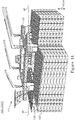
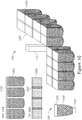
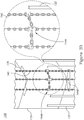
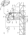
- Figures 1A-1G are high level schematic illustrations of an open-sea aquaculture system 100 , according to some embodiments of the invention.
- Figures 1A and 1B are perspective view
- Figures 1C and 1D are side views
- Figure 1E is a top view
- Figures 1F and 1G schematically illustrate columns and cages of system 100
- Figure 1G in a perspective view
- Elements from Figures 1A-1G may be combined in any operable combination, and the illustration of certain elements in certain figures and not in others merely serves an explanatory purpose and is non-limiting.
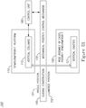
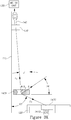
- Figure 2A is a high level schematic block diagram of open-sea aquaculture system 100 , according to some embodiments of the invention
- Figures 2B and 2C are high level schematic illustrations of positions and possible movements of open-sea aquaculture system 100 , according to some embodiments of the invention.
- Open-sea aquaculture system 100 is configured to operate at a large distance from the shore and to enable a continuous operation of aquaculture at open-sea.
- Open-sea aquaculture system 100 comprises a semisubmersible platform 110 , buoyant by its vertical columns 115 which are partly below ocean surface 90 (vertical columns 115 may be constructed as watertight pontoons).
- Semisubmersible platform 100 comprises an operating deck 111 having storage and maintenance facilities for supporting aquaculture and a plurality of vertical columns 115 .
- Operating deck 111 is located stably high above ( 116 ) sea level 90 and is not or almost not affected by wave action under rough sea conditions.
- Open-sea aquaculture system 100 is configured to withstand long operation periods at sea.
- Open-sea aquaculture system 100 further comprises a rigid assembly 120 of aquaculture cages 120A , 120B , etc. (see Figures 4A , 4D ).
- Rigid assembly 120 may comprise at least part of buoyancy mechanisms 127 or be independent therefrom
- Rigid assembly 120 comprises a plurality of vertical cavities 121 (see e.g., Figures 1A , 1F , 3A ) having forms configured to receive corresponding vertical columns 115 of semisubmersible platform 110 .
- vertical columns 115 are understood as any structural element of semisubmersible platform 110 which crosses water level 90 and receives rigid cage assembly 120 .
- rigid assembly 120 of aquaculture cages 120A , 120B, etc. are not limiting, in particular, rigid assembly 120 may extend far beyond the area of semisubmersible platform 110 to support a large number of cages, and may reach depths of several tens of meters.
- the cages themselves may be higher than wide, may be wider than high or may have similar height and width.
- the cages may be adapted to various types of aquaculture, e.g. fish, clams, ornamentals etc.
- the cages may be covered with nets (not shown) to maintain the cultured organisms within the cages.
- rigid cage assembly 120 may extend beyond the sides of platform 100 and extend horizontally and vertically according to required cage volumes.
- Rigid cage assembly 120 may enclose any water level crossing structures of platform 110 , which are generally related here in a non-limiting manner as being vertical columns.
- Buoyancy mechanisms 127 e.g., floats or other buoyancy mechanism such as inflatable tubes, containers or other elements which may change their buoyancy under control of control unit 160 ) may be connected to rigid cage assembly 120 at various position, providing buoyancy for rigid cage assembly 120 and control over the buoyancy of rigid cage assembly 120 , especially during raising and lowering rigid cage assembly 120 .
- Open-sea aquaculture system 100 comprises mechanical position control mechanism 130 (see Figures 1B , 1D ) configured to connect, mechanically, rigid assembly 120 to semisubmersible platform 110 , to limit a horizontal movements of rigid assembly 120 , and to control a relative position therebetween to provide at least two operational positions: a raised position 101 ( Figures 1A , 1C ), in which rigid assembly 120 encloses corresponding vertical columns 115 in vertical cavities 121 , and a lowered position 102 ( Figures 1B , 1D ) in which rigid assembly 120 is below corresponding vertical columns 115 .
- Mechanical position control mechanism 130 is configured to raise and lower rigid assembly 120 to maintain a required position of the cages with respect to sea level.
- Mechanical position control mechanism 130 may be configured to enable adjustment 101A, 102A of the depth of rigid assembly 120 within each of raised position 101 and lowered position 102 , respectively, to enable fine tuning of the cages' depth. It is noted that height 116 between operating deck 111 and sea level 90 is maintained in raised and lower positions 101 , 102 of rigid assembly 120 and assures that operating deck 111 is located stably and is not or almost not affected by wave action under rough sea conditions.
- sections of cages 120 may be reinforced by supports 120A, such as illustrated schematically in Figure 1F .
- Vertical cavities 121 may be open at one or two points on their perimeter, or may be fully enclosed by cages 120 .
- Vertical cavities 121 may be designed to be somewhat larger than the cross sections of vertical columns 115 and mechanical position control mechanism 130 may be configured to maintain vertical columns 115 within the volume of vertical cavities 121 and prevent an inner side 120B of cages 120 in vertical cavities 121 from contacting vertical columns 115 during the raising and lowering of cages and/or during regular operation of open-sea aquaculture system 100 .
- Guiding elements 132, 147A may be set on either or both vertical columns 115 and inner sides 120B of vertical cavities 121 to protect either or both from possible impacts and/or to guide their relative movements, as explained in detail below.
- cages 120 may be at least partially flexible and be made e.g., of flexible nets 120D , possibly held by one or more rigid cage parts 120C , 120E , as illustrated schematically in Figure 1G in perspective, side and top views and in Figure 2C as a schematic illustration.
- Mechanical position control mechanism 130 may be connected to at least one of rigid cage parts 120C, 120E to raise and lower cages 120 .
- Open-sea aquaculture system 100 further comprises a control unit 160 configured to control mechanical position control mechanism 130 to move rigid assembly 120 from raised to lowered position 101 , 102 , respectively, upon occurrence of specified rough sea conditions or operational requirements and to move rigid assembly 120 from lowered to raised position, 102 , 101 , respectively, upon specified conditions ( Figures 2A-2C ).
- Control unit 160 may be arranged to control mechanical position control mechanism 130 and to determine a depth of rigid assembly 120 with respect to sea level according to sea conditions or other operational requirements.
- Control unit 160 may comprise meteorological sensors and may be arranged to determine the optimal depth of rigid assembly 120 automatically with respect to measured and anticipated sea conditions, based on measurements from the meteorological sensors.
- regular operation under calm sea conditions may be carried out in raised position 101 while during storms (e.g., rough sea, high waves, strong currents etc.) rigid assembly 120 may be lowered to position 102 in which it is still connected to semisubmersible platform 110 but is maintained deeper in the sea and is allowed some horizontal movement 102B in response e.g., to strong current, to avoid damage to platform 110 by strong forces exerted on and by rigid assembly 120 under rough sea or strong currents conditions.
- the lowering of the cages reduces or prevents damage to the fish in them and also prevents application of mechanical forces between vertical columns 115 and cage assembly 120 .
- Mechanical position control mechanism 130 is configured to be strong enough to maintain rigid assembly 120 connected to semisubmersible platform 110 while allowing some horizontal freedom of movement 102B .
- cage assembly 120 may be in raised position 101 according to the requirements for the grown organisms.
- the disclosed mechanisms and control patterns provide protection to the fish or other organisms that are cultured, yet require a relatively small interventional effort - cage assembly 120 does not have to be moved horizontally (in raised position 101 ), and no additional vessel and personnel are required for protecting or moving the cages.
- the reaction times of control unit 160 are relatively short, as no intervention from shore is needed upon sea changes, and the sea conditions are measured at location (and not at shore) to provide most reliable data.
- Floats 127 with buoyancy control of rigid cage assembly 120 may be part of mechanical position control mechanism 130 , e.g., as a floating unit 137 , and may be controlled by control unit 160 to support the raising and lowering of rigid cage assembly 120 .
- Rigid cage assembly 120 may be semisubmersible by itself, with Floats 127 providing the buoyancy mechanism which may be controlled independently from and/or in relation to the buoyancy of semisubmersible platform 110 .
- semisubmersible platform 110 and cages 120 may be independently semisubmersible sub-systems which are associated by mechanical position control mechanism 130 , with vertical columns 115 and floats 127 providing the respective independent buoyancy mechanism (possibly with respective one or more control units controlling their buoyancy).
- Open-sea aquaculture system 100 may further comprise a guiding construction 165 configured to guide rigid assembly 120 when moving from lowered position 102 to raised position 101 , during the engagement of vertical columns 115 into vertical cavities 121 .
- Guiding construction 165 may be at least partly integrated with mechanical position control mechanism 130 , i.e., mechanical position control mechanism 130 may be configured to provide at least approximate proper positioning of vertical cavities 121 just below vertical columns 115 upon raising rigid assembly 120 from lowered position 102 to raised position 101 (see schematically in Figures 2B and 2C ).
- Guiding construction 165 may be further configured to protect vertical columns 115 and/or vertical cavities 121 and cages 120 during raising and lowering cages and/or during operation of open-sea aquaculture system 100 .
- Mechanical position control mechanism 130 may comprise a plurality of chains 140 connecting rigid assembly 120 to at least one motor unit 135 on platform 110 which is configured to release and collect chains 140 under control of control unit 160.
- Motor unit(s) 135 may be electric, hydraulic or of any type applicable to the required forces. Motor unit(s) 135 may be replaced and/or assisted by crane(s) onboard semisubmersible platform 110 .
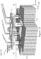
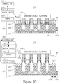
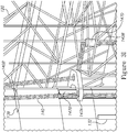
- FIGS 3A-3O are high level schematic illustrations of mechanical position control mechanisms 130 in open-sea aquaculture system 100 , according to some embodiments of the invention.
- Mechanical position control mechanism 130 may comprise a plurality of chains 140 connecting rigid assembly 120 to at least one motor unit 135 (including motor(s), pulley(s) etc., shown very schematically) on platform 110 (e.g., on vertical columns 115 ) which is configured to release and collect chains 140 , controllably by control unit 160 (see Figures 2B , 2C ).
- Guiding elements 132 , 139 in various configurations may be used to guide the relative motion of vertical columns 115 and vertical cavities 121 and prevent damaging them during operation of open-sea aquaculture system 100 at various sea conditions and operational requirements.
- Elements from Figures 3A-3G may be combined in any operable combination and operated within the context of any of the disclosed system configurations illustrated in Figures 1A-1G , 2A-2C , 4A-4D and 5 .
- the illustration of certain elements in certain figures and not in others merely serves an explanatory purpose and is non-limiting.
- Chains 140 may be guided along vertical columns 115 by one or more guides 131 , 139 ( Figure 3B ). Chains 140 may be connected to rigid assembly 120 at a corresponding plurality of attachment positions 146A , possibly stabilized and supported by additional connection structures 146 ( Figure 3C ). Attachment positions 146A may be selected to position the top openings of vertical cavities 121 of rigid assembly 120 against the bottoms of corresponding vertical columns 115 of semisubmersible platform 110 , upon raising rigid assembly 120 from lowered to raised position 102 , 101 respectively, by pulling chains 140 by motor unit(s) 135 .
- Chains 140 may be guided along at least lower sections of corresponding vertical columns 115 of semisubmersible platform 110 , e.g., by top and bottom guiding elements 131 , 139 , respectively ( Figure 3B ) to control chain movement and direction of forces conveyed by chains. Chains 140 may be guided in parallel along vertical columns 115 and may be stabilized by connecting and/or guiding members 144A , 144B ( Figures 3D , 3E ) and/or chains 140 may be guided together along vertical columns 115 and then split to multiple chains 140A ( Figure 3F ) before connecting to rigid assembly 120 .
- Open-sea aquaculture system 100 may further comprise guiding construction 165 (shown schematically in Figure 2A and implemented using various members in Figures 3A-3O , such as members 144A , 144B , 146 etc.). Guiding construction 165 may be configured to guide top openings of vertical cavities 121 of rigid assembly 120 toward bottoms of corresponding vertical columns 115 of semisubmersible platform 110 , upon raising rigid assembly 120 from lowered to raised position 102 , 101 , respectively (see a schematic explanation in Figure 3K and various embodiments in Figures 3A-3O ) .
- Guiding construction 165 may comprise multiple members, arranged geometrically and with respect to applied forces in a way that brings the top openings of vertical cavities 121 into the correct position below the bottoms of corresponding vertical columns 115 upon pulling chains 140 upwards by motor unit(s) 135 (see a schematic explanation in Figure 3K and various embodiments in Figures 3A-3O ) .
- guiding construction 165 may comprise the configuration of chains 140A , connection structures 146 connecting chains 140A to rigid cage assembly 120 , top and bottom guiding elements 131 , 139 and edge guiding elements 144 on vertical columns 115 , as well as guiding elements 132 on vertical columns 115 and possibly on the inner sides of cavities 121 (not shown), configured to absorb mechanical shocks and guide the moving rigid cage assembly 120 up and down along vertical columns 115 in vertical movement 101A (see also Figures 3B and 3C ).
- Guiding construction 165 may be configured to balance forces operating sideways during the raising and lowering of cages 120 to reduce or prevent lateral movement of cages 120 with respect to columns 115 and keep vertical columns 115 more or less centrally within vertical cavities 121 and prevent mutual impacts of vertical columns 115 and inner sides 120B of cages 120 in vertical cavities 121 .
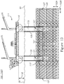
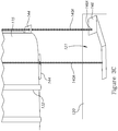
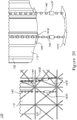
- Figure 3E schematically illustrates mechanical position control mechanism 130 , according to some embodiments of the invention.
- Figure 3E schematically illustrates mechanical position control mechanism 130 on one of columns 115 in lowered position 102 and in raised position 101 in side view, as well as details of guiding elements in mechanical position control mechanism 130 .
- Mechanical position control mechanism 130 may comprise parallel chains 140, guided along vertical columns 115 (e.g., by guiding elements 139 , 144 , 144A ), e.g., along edges of columns 115 .
- Guiding elements 139 , 144 and/or 144A may be configured to stabilize chains 140 and maintain their parallel configuration during operation of mechanical position control mechanism 130 .
- guiding element(s) 144A shown in detail in cross section of column 115 may be configured to maintain a relative position of the chains 140 , minimize the horizontal movements of rigid cage assembly 120 and/or minimize the relative motion between cage assembly 120 and vertical columns 115 , as explained below in more details.
- Parallel chains 140 may be connected to rigid cage assembly 120 via connection structures 146 at different heights along rigid cage assembly 120 , selected to assure the stability of rigid cage assembly 120 in lowered position 102 and simplify the raising of rigid cage assembly 120 from lowered position 102 to raised position 101 , with cavities 121 enclosing columns 115 .
- Figure 3F schematically illustrates usage of multiple chains 140A in mechanical position control mechanism 130 , according to some embodiments of the invention.
- Chains 140 may in some embodiments be split into multiple chains 140A that are anchored on cages 120 , raise and lower cages 120 and maintain the relative position of vertical columns 115 in vertical cavities 121 .
- Guides 139 , 142 may be configured to guide and control the paths of chains 140A during the operation of system 100.
- Figures 3G-3J schematically illustrate various elements of mechanical position control mechanism 130 , according to some embodiments of the invention.
- One or more chain assemblies may be positioned at corners of vertical columns 115 .
- Figures 3G-3J illustrate as an example such a chain assembly, possibly located along the respective external edge of vertical columns 115 .
- Guides 139 , 147A may be configured to guide chains 140 along vertical column 115 and/or to direct one or more chain 140B along a path that distances from vertical column 115 to improve the force application pattern of cages 120 , as explained below.
- Guide 139 may be a fixed top plate guide and guide 147A may be a movable central plate, guided along support(s) 147B .
- Additional guides 147D may be used to assure correct motion of chain(s) 140B upon raising and lowering cages 120, and supports 147B (e.g., as an I-beam guide) may be provided to mechanically stabilize mechanical position control mechanism 130 and possibly to enable movement of guide 147A along vertical column 115 .
- Shock absorber(s) 147E may be located at different locations (shown as an example close to the connection of chain 140B to member 147C , possibly similar to connection structure 146 ) to attenuate shocks to mechanical position control mechanism 130 .
- Edge guiding elements 144 may be positioned below movable support 147A and possibly function as a stopper thereto (see Figure 3J ).
- Movable support 147A may be guided along support(s) 147B by various means.
- One or more chains 140 may be replaced by rod(s) and/or cable(s) and/or any other tension applying member.
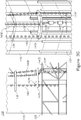
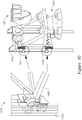
- Figure 3K is a high level schematic example for application of forces on chains 140 by motor unit 135 and by cages 120 , according to some embodiments of the invention.
- Mechanical position control mechanism 130 is configured to raise and lower cages 120 while maintaining a relative position of the chains 140 and minimizing the horizontal movements of cages 120 when guided along vertical columns 115 .
- mechanical position control mechanism 130 is configured to control and carry out the transitions between raised position 101 and lowered position 102 , wherein in the former cages 120 are moved along vertical columns 115 (movement 101A ) and in the latter cages 120 are freely connected to vertical columns 115 and may move horizontally below vertical columns 115 without impacting them (movement 102B ), as illustrated schematically in Figures 2A-2C .
- mechanical position control mechanism 130 is configured to apply forces in an accurate manner to engage cages 120 onto columns 115 ( 102 ⁇ 101 ) to fit columns 115 into cavities 121 without damaging any of them while applying the immense forces required to carry out this transition.
- Mechanical position control mechanism 130 is further configured to carry out the opposite transition ( 101 ⁇ 102 ) while avoiding damage to cages 120 and columns 115 .
- the force marked F c in Figure 3K reaches between 600-1200 tons and the vertical component of the vertical force on movable support 147A may reach 300-700 tons.
- Mechanical position control mechanism 130 may be configured accordingly to enable the application of such large forces reliably and accurately. It is emphasized that correct angles may be maintained to prevent impacts of cages 120 on columns 115 .
- FIG. 3L illustrates schematically a positioning mechanism 134 for controlling the position of movable guide 147A , according to some embodiments of the invention.
- Illustrated positioning mechanism 134 may be configured to position movable guide 147A at a height which is appropriate to prevent contact between cages 120 and vertical columns 115 , as derived e.g., from force calculations illustrated schematically in Figure 3K above, from realtime measurements, simulations, etc.
- positioning mechanism 134 may be configured to position movable guide 147A at a constant height above cages 120, i.e., raise movable guide 147A when cages 120 are raised and lower movable guide 147A when cages 120 are lowered.
- Positioning mechanism 134 may comprise a motor unit 136 (e.g., independent of motor unit 135 ) and a closed chain loop 141 (as a non-limiting example) to control the height of movable guide 147A along vertical columns 115 .
- Figures 3M-3O schematically illustrate elements of mechanical position control mechanism 130 , according to some embodiments of the invention.
- mechanical position control mechanism 130 may be configured to use cables 140 (e.g., multi-wire cables), possibly with a sheave system instead or in addition to chains 140 . Multiple cables may reduce the force in each cable with respect to F c , using corresponding winches to anchor cables 140 on cages 120 , e.g., via heave compensator(s) 149B. Cages 120 may be guided along columns 115 using guides 147B and possibly gripper and/or brakes 149A as movement limiters.
- cables 140 e.g., multi-wire cables
- Multiple cables may reduce the force in each cable with respect to F c , using corresponding winches to anchor cables 140 on cages 120 , e.g., via heave compensator(s) 149B.
- Cages 120 may be guided along columns 115 using guides 147B and possibly gripper and/or brakes 149A as movement limiters
- Guides 147B may be associated with cages 120 by a movable assembly 149C which may comprise shafts (with radial and/or axial bearing(s)) with shock absorbers 149D (e.g., hydraulic shock absorbers, possibly connected and moved by a chain drive and/or a pulley system, not shown) connected by joints 149E such as universal joints to columns 115 and cages 120 .
- a movable assembly 149C which may comprise shafts (with radial and/or axial bearing(s)) with shock absorbers 149D (e.g., hydraulic shock absorbers, possibly connected and moved by a chain drive and/or a pulley system, not shown) connected by joints 149E such as universal joints to columns 115 and cages 120 .
- Figure 3N illustrates schematically a configuration of movable assembly 149C according to certain embodiments of the invention, in side view and in top plan view from the surface marked "A-A”.
- Figure 3O illustrates schematically an alternative configuration of mov
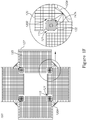
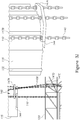
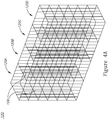
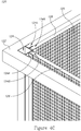
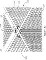
- FIGS 4A-4D are high level schematic illustrations of cage configurations in rigid cage assembly 120 , according to some embodiments of the invention.
- Rigid cage assembly 120 comprises a plurality of cages 120A , 120B , 120C , 120D etc. separated by cage grids 126 , which are shown schematically in a non-limiting manner, and may be rigid or at least partially flexible.
- Rigid cage assembly 120 may comprise a framework 122 with connecting members 124 that provide the backbone of rigid cage assembly 120 ( Figure 4B ) as well as multiple rails 124A , 124B configured to receive multiple cage grids 126 that define aquaculture cages 120A , 120B etc.
- Cage grids 126 may be covered by rigid or flexible nets 125 configured to maintain the animals in aquaculture in the respective cages.
- a corresponding framework 124 may be configured to support rails 124A , 124B etc., configured to receive cage grids 126 , possibly in a modular manner that enables to modify cage volumes according by introducing cage grids 126 into corresponding rails 124A , 124B etc. ( Figure 4C ).
- At least some of rails 124A , 124B may be double rails 124A , 124B , configured to enable replacement of corresponding cage grids 126 without disassembling cages 120A , 120B , 120C , 120D etc., by introducing an additional cage grid 126 before removing former cage grid 126 ( Figure 4D ).
- Figure 4C the empty rails 124A , ready to receive an additional cage grid 126 (not illustrated) if required while maintaining former cage grid 126 (illustrated) in occupied rail 124B .
- Frameworks 122 , 124 may be configured to support mechanically rigid cage assembly 120 and rails 124A , 124B with cage grids 126 upon raising and lowering whole mechanically rigid cage assembly 120 between raised and lowered positions 101 , 102 , respectively, and during regular offshore operation of open-sea aquaculture system 100 .
- rigid cage assembly 120 may be constructed in any way, modular or not modular.
- rails 124A , 124B may be used in certain embodiments of cage assembly 120 , while other embodiments may comprise a permanent assembly of some or all of cage grids 126 , or assembly of at least some cage grids 126 in a manner different from described above.
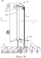
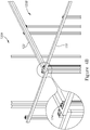
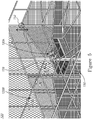
- FIG. 5 is a high level schematic illustration of a movable cage floor 150, used for fish handling in open-sea aquaculture system 100 , according to some embodiments of the invention.
- Rigid cage assembly 120 may be configured to enable volume changes and adaptation in at least some of cages 120 .
- the volume and depth of cages 120 may be adapted according to the specific aquaculture use, i.e., according to specific types of animals grown in the cages, their developmental stages and required conditions (sea conditions, density conditions etc.).
- Rigid cage assembly 120 may also be configured to enable moving ( 159 ) of fish or other types of animals in aquaculture from cage ( 120A ) to cage ( 120B ) to support different growth stages, to enable cage repair if needed, and to harvest the fish in a controlled and safe manner.
- At least some of aquaculture cages 120A may comprise a vertically movable partition 150 connected by a partition positioning apparatus 152 to cage 120A (e.g., a roller with supporting members) which is possibly controlled by control unit 160 ).
- Vertically movable partition 150 may be horizontal or tilted and may have a revolving door mechanism at its bottom. Vertically movable partition 150 may enable moving fish from cage to cage through designated openings (e.g., removable cage grids 126 or cage grid parts).
- Partition 150 may be moved by motor(s) and chains, possibly in association with mechanical position control mechanisms 130 . Movements of partition 150 may be coordinated with movements of rigid cage assembly 120 (e.g., from raised to lowered position 101 , 102 , respectively) in order to protect the fish and make the change in conditions gradual. For example upon forecasts of rough sea, fish may be lowered within the cages by partition(s) 150 , and upon realization of the forecast rigid cage assembly 120 may be lowered while partition(s) 150 may be temporally raised, to allow more time for accommodation of the fish. Eventually, when maximal depth (e.g., in lowered position 102 ) is required, partition(s) 150 may be lowered even in lowered position 102. Partition(s) 150 may be further used to control the types or sizes of fish within each cage.
- Open-sea aquaculture system 100 may further comprise a sorting system (not shown), arranged to sort fish by size and move them between cages 120A , 120B etc. according to their size as they grow.
- Maintenance facilities 111 may comprise a computerized center for monitoring the cages and the fish (visually, chemically, and/or using environmental sensors such as oxygen, temperature, salinity sensors, and so forth), for example, measure the biomass of the fish, manage and control the feeding process, detect signs for diseases, and allow the crew to continuously supervise the aquaculture.
- Offshore open-sea aquaculture system 100 may further comprise facilities 111 that allow the crew to perform maintenance around the clock, with cages below water, including disassembling and replacing parts.
- Semisubmersible platform 110 may comprise ship mooring facilities allowing for supplies and fish transport, and helicopter landing gear.
- Figure 6 is a high level flowchart illustrating an open-sea aquaculture method 200 , according to some embodiments of the invention.
- Method 200 may be implemented by system 100 and system may be configured to operate method 200 .
- Some of the listed stages are optional, and the order of the stages may be changed according to operational considerations.
- Method 200 comprises connecting, mechanically, a rigid assembly of aquaculture cages to a semisubmersible platform which comprises a plurality of vertical columns (stage 202 ), the semisubmersible platform configured to have storage and maintenance facilities for supporting aquaculture (stage 204 ).
- the rigid assembly is configured to comprise a plurality of vertical cavities formed to receive corresponding vertical columns of the semisubmersible platform (stage 210 ).
- Method 200 further comprises configuring the mechanical connection to provide a controllable relative position between the rigid assembly and the semisubmersible platform, comprising at least two operational positions (stage 220 ): a raised position configured to have the rigid assembly enclose the corresponding vertical columns in the vertical cavities (stage 230 ) to limit a horizontal movement of the rigid assembly (stage 232 ) while possibly enabling vertical positional adjustment in the raised position (stage 235 ), and a lowered position configured to have the rigid assembly below the corresponding vertical columns (stage 240 ), possibly allowing some horizontal and vertical movement of the rigid assembly in the lowered position (stage 245 ).
- Method 200 further comprises controlling the relative position between the rigid assembly and the semisubmersible platform (stage 250 ) to move the rigid assembly from the raised to the lowered position upon occurrence of specified rough sea conditions, or at any other time as needed and to move the rigid assembly from the lowered to the raised position upon specified conditions (stage 260 ) and moving the rigid assembly from the lowered to the raised position upon specified conditions such as calm sea (stage 270 ).
- Method 200 may further comprise guiding top openings of the vertical cavities of the rigid assembly toward bottoms of the corresponding vertical columns of the semisubmersible platform, upon raising the rigid assembly from the lowered to the raised position (stage 280 ).
- Method 200 may further comprise configuring the mechanical connection to comprise a plurality of chains connecting the rigid assembly to at least one motor unit on the platform (stage 290 ), and configuring the at least one motor unit to controllably release and collect the chains (stage 295 ).
- Method 200 may further comprise connecting the chains to the rigid assembly at a corresponding plurality of attachment positions which are selected to position top openings of the vertical cavities of the rigid assembly against bottoms of the corresponding vertical columns of the semisubmersible platform, upon raising the rigid assembly from the lowered to the raised position by pulling of the chains by the at least one motor unit (stage 300 ).
- Method 200 may further comprise guiding the chains along at least lower sections of the corresponding vertical columns of the semisubmersible platform (stage 305 ).
- method 200 may further comprise configuring the rigid assembly to have a plurality of rails configured to receive a plurality of cage grids that define the aquaculture cages (stage 310 ).
- Method 200 may further comprise configuring at least some of the rails as double rails that enable replacement of corresponding cage grids without disassembling the cages (stage 315 ).
- Using rails is an optional feature, and method 200 may be carried out without stages 310 and 315 .
- Method 200 may further comprise configuring and using vertically movable partitions in at least some of the aquaculture cages to control cage volume, to move fish from cage to cage and/or to remove fish from the cages (stage 320 ).
- an embodiment is an example or implementation of the invention.
- the various appearances of "one embodiment”, “an embodiment”, “certain embodiments” or “some embodiments” do not necessarily all refer to the same embodiments.
- various features of the invention may be described in the context of a single embodiment, the features may also be provided separately or in any suitable combination.
- the invention may also be implemented in a single embodiment.
- Certain embodiments of the invention may include features from different embodiments disclosed above, and certain embodiments may incorporate elements from other embodiments disclosed above.
- the disclosure of elements of the invention in the context of a specific embodiment is not to be taken as limiting their use in the specific embodiment alone.
- the invention can be carried out or practiced in various ways and that the invention can be implemented in certain embodiments other than the ones outlined in the description above.
Description
- The present invention relates to the field of aquaculture, and more particularly, to offshore aquaculture.
- Offshore aquaculture is experiencing an expansion but has to cope with rougher sea conditions than the more traditional near-shore aquaculture.
- U.K. Patent No.
GB 2,501,879 WO2016/128981A1 , discloses a sea or ocean vessel for carrying out fish farming in deep water comprising a hull and one or more fish cages. The fish cage is fixedly or movably attached to the hull, for example on a steel frame, the vessel having a floating state in which the fish cage is at the sea surface level and a submerged state in which the fish cage is sufficiently below the water surface level, five and more typically fifteen meters or deeper, to be substantially unaffected by storm conditions at the surface. Either the vessel itself may be submerged, or the cages may be lowered down the side of the vessel. - The following is a simplified summary providing an initial understanding of the invention. The summary does not necessarily identify key elements nor limit the scope of the invention, but merely serves as an introduction to the following description.
- One aspect of the present invention provides an open-sea aquaculture system according to
claim 1, comprising: a semisubmersible platform having storage and maintenance facilities for supporting aquaculture, the semisubmersible platform comprising and being buoyant by a plurality of vertical columns which are partly below an ocean surface, and at least one motor unit, a rigid assembly of aquaculture cages, the rigid assembly comprising a plurality of vertical cavities having forms configured to receive corresponding vertical columns of the semisubmersible platform, a mechanical position control mechanism comprising a plurality of tension applying members configured to connect, mechanically, the rigid assembly to the at least one motor unit on said semisubmersible platform and control a relative position therebetween to provide at least two operational positions: (i) a raised position in which the rigid assembly encloses the corresponding vertical columns in the vertical cavities to limit a horizontal movement of the rigid assembly, and (ii) a lowered position in which the rigid assembly is below the corresponding vertical columns, and a control unit configured to control the mechanical position control mechanism and the at least one motor unit to move the rigid assembly from the raised to the lowered position upon occurrence of specified rough sea conditions, or whenever needed, and to move the rigid assembly from the lowered to the raised position upon specified conditions and a guiding construction, configured to guide top openings of the vertical cavities of the rigid assembly toward bottoms of the corresponding vertical columns of the semisubmersible platform, upon raising the rigid assembly from the lowered to the raised position. - These, additional, and/or other aspects and/or advantages of the present invention are set forth in the detailed description which follows; possibly inferable from the detailed description; and/or learnable by practice of the present invention.
- For a better understanding of embodiments of the invention and to show how the same may be carried into effect, reference will now be made, purely by way of example, to the accompanying drawings in which like numerals designate corresponding elements or sections throughout.
- In the accompanying drawings:
-
Figures 1A-1G are high level schematic illustrations of an open-sea aquaculture system, according to some embodiments of the invention. -
Figure 2A is a high level schematic block diagram of the open-sea aquaculture system, according to some embodiments of the invention. -
Figures 2B and2C are a high level schematic illustration of positions and possible movements of the open-sea aquaculture system, according to some embodiments of the invention. -
Figures 3A-3O are high level schematic illustrations of mechanical position control mechanisms in the open-sea aquaculture system, according to some embodiments of the invention. -
Figures 4A-4D are high level schematic illustrations of cage configurations in the rigid cage assembly, according to some embodiments of the invention -
Figure 5 is a high level schematic illustration of a movable cage floor, used for fish handling in the open-sea aquaculture system, according to some embodiments of the invention. -
Figure 6 is a high level flowchart illustrating an open-sea aquaculture method, according to some embodiments of the invention. - In the following description, various aspects of the present invention are described. For purposes of explanation, specific configurations and details are set forth in order to provide a thorough understanding of the present invention. However, it will also be apparent to one skilled in the art that the present invention may be practiced without the specific details presented herein. Furthermore, well known features may have been omitted or simplified in order not to obscure the present invention. With specific reference to the drawings, it is stressed that the particulars shown are by way of example and for purposes of illustrative discussion of the present invention only, and are presented in the cause of providing what is believed to be the most useful and readily understood description of the principles and conceptual aspects of the invention. In this regard, no attempt is made to show structural details of the invention in more detail than is necessary for a fundamental understanding of the invention, the description taken with the drawings making apparent to those skilled in the art how the several forms of the invention may be embodied in practice.
- Before at least one embodiment of the invention is explained in detail, it is to be understood that the invention is not limited in its application to the details of construction and the arrangement of the components set forth in the following description or illustrated in the drawings. The invention is applicable to other embodiments that may be practiced or carried out in various ways as well as to combinations of the disclosed embodiments. Also, it is to be understood that the phraseology and terminology employed herein is for the purpose of description and should not be regarded as limiting.
- Unless specifically stated otherwise, as apparent from the following discussions, it is appreciated that throughout the specification discussions utilizing terms such as "processing", "computing", "calculating", "determining", "enhancing" or the like, refer to the action and/or processes of a computer or computing system, or similar electronic computing device, that manipulates and/or transforms data represented as physical, such as electronic, quantities within the computing system's registers and/or memories into other data similarly represented as physical quantities within the computing system's memories, registers or other such information storage, transmission or display devices. Any of the disclosed modules or units may be at least partially implemented by a computer processor.
-
Figures 1A-1G are high level schematic illustrations of an open-sea aquaculture system 100, according to some embodiments of the invention.Figures 1A and1B are perspective view,Figures 1C and1D are side views,Figure 1E is a top view andFigures 1F and1G schematically illustrate columns and cages ofsystem 100,Figure 1F in a top view of a horizontal cross section below the sea level andFigure 1G in a perspective view. Elements fromFigures 1A-1G may be combined in any operable combination, and the illustration of certain elements in certain figures and not in others merely serves an explanatory purpose and is non-limiting.Figure 2A is a high level schematic block diagram of open-sea aquaculture system 100, according to some embodiments of the invention, andFigures 2B and2C are high level schematic illustrations of positions and possible movements of open-sea aquaculture system 100, according to some embodiments of the invention. - Open-
sea aquaculture system 100 is configured to operate at a large distance from the shore and to enable a continuous operation of aquaculture at open-sea. Open-sea aquaculture system 100 comprises asemisubmersible platform 110, buoyant by itsvertical columns 115 which are partly below ocean surface 90 (vertical columns 115 may be constructed as watertight pontoons).Semisubmersible platform 100 comprises anoperating deck 111 having storage and maintenance facilities for supporting aquaculture and a plurality ofvertical columns 115.Operating deck 111 is located stably high above (116)sea level 90 and is not or almost not affected by wave action under rough sea conditions. Open-sea aquaculture system 100 is configured to withstand long operation periods at sea. - Open-
sea aquaculture system 100 further comprises arigid assembly 120 ofaquaculture cages Figures 4A ,4D ).Rigid assembly 120 may comprise at least part ofbuoyancy mechanisms 127 or be independenttherefrom Rigid assembly 120 comprises a plurality of vertical cavities 121 (see e.g.,Figures 1A ,1F ,3A ) having forms configured to receive correspondingvertical columns 115 ofsemisubmersible platform 110. It is noted thatvertical columns 115 are understood as any structural element ofsemisubmersible platform 110 which crosseswater level 90 and receivesrigid cage assembly 120. - The dimensions and forms of
rigid assembly 120 ofaquaculture cages rigid assembly 120 may extend far beyond the area ofsemisubmersible platform 110 to support a large number of cages, and may reach depths of several tens of meters. The cages themselves may be higher than wide, may be wider than high or may have similar height and width. The cages may be adapted to various types of aquaculture, e.g. fish, clams, ornamentals etc. The cages may be covered with nets (not shown) to maintain the cultured organisms within the cages. As shown inFigure 1E ,rigid cage assembly 120 may extend beyond the sides ofplatform 100 and extend horizontally and vertically according to required cage volumes.Rigid cage assembly 120 may enclose any water level crossing structures ofplatform 110, which are generally related here in a non-limiting manner as being vertical columns. - Buoyancy mechanisms 127 (e.g., floats or other buoyancy mechanism such as inflatable tubes, containers or other elements which may change their buoyancy under control of control unit 160) may be connected to
rigid cage assembly 120 at various position, providing buoyancy forrigid cage assembly 120 and control over the buoyancy ofrigid cage assembly 120, especially during raising and loweringrigid cage assembly 120. - Open-
sea aquaculture system 100 comprises mechanical position control mechanism 130 (seeFigures 1B ,1D ) configured to connect, mechanically,rigid assembly 120 tosemisubmersible platform 110, to limit a horizontal movements ofrigid assembly 120, and to control a relative position therebetween to provide at least two operational positions: a raised position 101 (Figures 1A ,1C ), in whichrigid assembly 120 encloses correspondingvertical columns 115 invertical cavities 121, and a lowered position 102 (Figures 1B ,1D ) in whichrigid assembly 120 is below correspondingvertical columns 115. Mechanicalposition control mechanism 130 is configured to raise and lowerrigid assembly 120 to maintain a required position of the cages with respect to sea level. Mechanicalposition control mechanism 130 may be configured to enableadjustment rigid assembly 120 within each of raisedposition 101 and loweredposition 102, respectively, to enable fine tuning of the cages' depth. It is noted thatheight 116 betweenoperating deck 111 andsea level 90 is maintained in raised andlower positions rigid assembly 120 and assures thatoperating deck 111 is located stably and is not or almost not affected by wave action under rough sea conditions. - In certain embodiments, sections of
cages 120 may be reinforced bysupports 120A, such as illustrated schematically inFigure 1F .Vertical cavities 121 may be open at one or two points on their perimeter, or may be fully enclosed bycages 120.Vertical cavities 121 may be designed to be somewhat larger than the cross sections ofvertical columns 115 and mechanicalposition control mechanism 130 may be configured to maintainvertical columns 115 within the volume ofvertical cavities 121 and prevent aninner side 120B ofcages 120 invertical cavities 121 from contactingvertical columns 115 during the raising and lowering of cages and/or during regular operation of open-sea aquaculture system 100. Guidingelements vertical columns 115 andinner sides 120B ofvertical cavities 121 to protect either or both from possible impacts and/or to guide their relative movements, as explained in detail below. - In certain embodiments,
cages 120 may be at least partially flexible and be made e.g., offlexible nets 120D, possibly held by one or morerigid cage parts Figure 1G in perspective, side and top views and inFigure 2C as a schematic illustration. Mechanicalposition control mechanism 130 may be connected to at least one ofrigid cage parts lower cages 120. - Open-
sea aquaculture system 100 further comprises acontrol unit 160 configured to control mechanicalposition control mechanism 130 to moverigid assembly 120 from raised to loweredposition rigid assembly 120 from lowered to raised position, 102, 101, respectively, upon specified conditions (Figures 2A-2C ).Control unit 160 may be arranged to control mechanicalposition control mechanism 130 and to determine a depth ofrigid assembly 120 with respect to sea level according to sea conditions or other operational requirements.Control unit 160 may comprise meteorological sensors and may be arranged to determine the optimal depth ofrigid assembly 120 automatically with respect to measured and anticipated sea conditions, based on measurements from the meteorological sensors. - For example, regular operation under calm sea conditions may be carried out in raised
position 101 while during storms (e.g., rough sea, high waves, strong currents etc.)rigid assembly 120 may be lowered toposition 102 in which it is still connected tosemisubmersible platform 110 but is maintained deeper in the sea and is allowed somehorizontal movement 102B in response e.g., to strong current, to avoid damage toplatform 110 by strong forces exerted on and byrigid assembly 120 under rough sea or strong currents conditions. The lowering of the cages reduces or prevents damage to the fish in them and also prevents application of mechanical forces betweenvertical columns 115 andcage assembly 120. Mechanicalposition control mechanism 130 is configured to be strong enough to maintainrigid assembly 120 connected tosemisubmersible platform 110 while allowing some horizontal freedom ofmovement 102B. During calm sea periods,cage assembly 120 may be in raisedposition 101 according to the requirements for the grown organisms. The disclosed mechanisms and control patterns provide protection to the fish or other organisms that are cultured, yet require a relatively small interventional effort -cage assembly 120 does not have to be moved horizontally (in raised position 101), and no additional vessel and personnel are required for protecting or moving the cages. Moreover, the reaction times ofcontrol unit 160 are relatively short, as no intervention from shore is needed upon sea changes, and the sea conditions are measured at location (and not at shore) to provide most reliable data. -
Floats 127 with buoyancy control ofrigid cage assembly 120 may be part of mechanicalposition control mechanism 130, e.g., as a floatingunit 137, and may be controlled bycontrol unit 160 to support the raising and lowering ofrigid cage assembly 120.Rigid cage assembly 120 may be semisubmersible by itself, withFloats 127 providing the buoyancy mechanism which may be controlled independently from and/or in relation to the buoyancy ofsemisubmersible platform 110. In certain embodiments,semisubmersible platform 110 andcages 120 may be independently semisubmersible sub-systems which are associated by mechanicalposition control mechanism 130, withvertical columns 115 and floats 127 providing the respective independent buoyancy mechanism (possibly with respective one or more control units controlling their buoyancy). - Open-
sea aquaculture system 100 may further comprise a guidingconstruction 165 configured to guiderigid assembly 120 when moving from loweredposition 102 to raisedposition 101, during the engagement ofvertical columns 115 intovertical cavities 121. Guidingconstruction 165 may be at least partly integrated with mechanicalposition control mechanism 130, i.e., mechanicalposition control mechanism 130 may be configured to provide at least approximate proper positioning ofvertical cavities 121 just belowvertical columns 115 upon raisingrigid assembly 120 from loweredposition 102 to raised position 101 (see schematically inFigures 2B and2C ). Guidingconstruction 165 may be further configured to protectvertical columns 115 and/orvertical cavities 121 andcages 120 during raising and lowering cages and/or during operation of open-sea aquaculture system 100. - Mechanical
position control mechanism 130 may comprise a plurality ofchains 140 connectingrigid assembly 120 to at least onemotor unit 135 onplatform 110 which is configured to release and collectchains 140 under control ofcontrol unit 160. Motor unit(s) 135 may be electric, hydraulic or of any type applicable to the required forces. Motor unit(s) 135 may be replaced and/or assisted by crane(s)onboard semisubmersible platform 110. -
Figures 3A-3O are high level schematic illustrations of mechanicalposition control mechanisms 130 in open-sea aquaculture system 100, according to some embodiments of the invention. Mechanicalposition control mechanism 130 may comprise a plurality ofchains 140 connectingrigid assembly 120 to at least one motor unit 135 (including motor(s), pulley(s) etc., shown very schematically) on platform 110 (e.g., on vertical columns 115) which is configured to release and collectchains 140, controllably by control unit 160 (seeFigures 2B ,2C ). Guidingelements vertical columns 115 andvertical cavities 121 and prevent damaging them during operation of open-sea aquaculture system 100 at various sea conditions and operational requirements. Elements fromFigures 3A-3G may be combined in any operable combination and operated within the context of any of the disclosed system configurations illustrated inFigures 1A-1G ,2A-2C ,4A-4D and5 . The illustration of certain elements in certain figures and not in others merely serves an explanatory purpose and is non-limiting. -
Chains 140 may be guided alongvertical columns 115 by one ormore guides 131, 139 (Figure 3B ).Chains 140 may be connected torigid assembly 120 at a corresponding plurality ofattachment positions 146A, possibly stabilized and supported by additional connection structures 146 (Figure 3C ).Attachment positions 146A may be selected to position the top openings ofvertical cavities 121 ofrigid assembly 120 against the bottoms of correspondingvertical columns 115 ofsemisubmersible platform 110, upon raisingrigid assembly 120 from lowered to raisedposition chains 140 by motor unit(s) 135. -
Chains 140 may be guided along at least lower sections of correspondingvertical columns 115 ofsemisubmersible platform 110, e.g., by top andbottom guiding elements Figure 3B ) to control chain movement and direction of forces conveyed by chains.Chains 140 may be guided in parallel alongvertical columns 115 and may be stabilized by connecting and/or guidingmembers Figures 3D ,3E ) and/orchains 140 may be guided together alongvertical columns 115 and then split tomultiple chains 140A (Figure 3F ) before connecting torigid assembly 120. - Open-
sea aquaculture system 100 may further comprise guiding construction 165 (shown schematically inFigure 2A and implemented using various members inFigures 3A-3O , such asmembers construction 165 may be configured to guide top openings ofvertical cavities 121 ofrigid assembly 120 toward bottoms of correspondingvertical columns 115 ofsemisubmersible platform 110, upon raisingrigid assembly 120 from lowered to raisedposition Figure 3K and various embodiments inFigures 3A-3O ). Guidingconstruction 165 may comprise multiple members, arranged geometrically and with respect to applied forces in a way that brings the top openings ofvertical cavities 121 into the correct position below the bottoms of correspondingvertical columns 115 upon pullingchains 140 upwards by motor unit(s) 135 (see a schematic explanation inFigure 3K and various embodiments inFigures 3A-3O ). For example, guidingconstruction 165 may comprise the configuration ofchains 140A,connection structures 146 connectingchains 140A torigid cage assembly 120, top andbottom guiding elements edge guiding elements 144 onvertical columns 115, as well as guidingelements 132 onvertical columns 115 and possibly on the inner sides of cavities 121 (not shown), configured to absorb mechanical shocks and guide the movingrigid cage assembly 120 up and down alongvertical columns 115 invertical movement 101A (see alsoFigures 3B and3C ). Guidingconstruction 165 may be configured to balance forces operating sideways during the raising and lowering ofcages 120 to reduce or prevent lateral movement ofcages 120 with respect tocolumns 115 and keepvertical columns 115 more or less centrally withinvertical cavities 121 and prevent mutual impacts ofvertical columns 115 andinner sides 120B ofcages 120 invertical cavities 121. -
Figure 3E schematically illustrates mechanicalposition control mechanism 130, according to some embodiments of the invention.Figure 3E schematically illustrates mechanicalposition control mechanism 130 on one ofcolumns 115 in loweredposition 102 and in raisedposition 101 in side view, as well as details of guiding elements in mechanicalposition control mechanism 130. Mechanicalposition control mechanism 130 may compriseparallel chains 140, guided along vertical columns 115 (e.g., by guidingelements columns 115. Guidingelements chains 140 and maintain their parallel configuration during operation of mechanicalposition control mechanism 130. In particular guiding element(s) 144A shown in detail in cross section ofcolumn 115 may be configured to maintain a relative position of thechains 140, minimize the horizontal movements ofrigid cage assembly 120 and/or minimize the relative motion betweencage assembly 120 andvertical columns 115, as explained below in more details.Parallel chains 140 may be connected torigid cage assembly 120 viaconnection structures 146 at different heights alongrigid cage assembly 120, selected to assure the stability ofrigid cage assembly 120 in loweredposition 102 and simplify the raising ofrigid cage assembly 120 from loweredposition 102 to raisedposition 101, withcavities 121 enclosingcolumns 115. -
Figure 3F schematically illustrates usage ofmultiple chains 140A in mechanicalposition control mechanism 130, according to some embodiments of the invention.Chains 140 may in some embodiments be split intomultiple chains 140A that are anchored oncages 120, raise andlower cages 120 and maintain the relative position ofvertical columns 115 invertical cavities 121.Guides chains 140A during the operation ofsystem 100. -
Figures 3G-3J schematically illustrate various elements of mechanicalposition control mechanism 130, according to some embodiments of the invention. One or more chain assemblies may be positioned at corners ofvertical columns 115.Figures 3G-3J illustrate as an example such a chain assembly, possibly located along the respective external edge ofvertical columns 115.Guides chains 140 alongvertical column 115 and/or to direct one ormore chain 140B along a path that distances fromvertical column 115 to improve the force application pattern ofcages 120, as explained below.Guide 139 may be a fixed top plate guide and guide 147A may be a movable central plate, guided along support(s) 147B.Additional guides 147D may be used to assure correct motion of chain(s) 140B upon raising and loweringcages 120, and supports 147B (e.g., as an I-beam guide) may be provided to mechanically stabilize mechanicalposition control mechanism 130 and possibly to enable movement ofguide 147A alongvertical column 115. Shock absorber(s) 147E may be located at different locations (shown as an example close to the connection ofchain 140B tomember 147C, possibly similar to connection structure 146) to attenuate shocks to mechanicalposition control mechanism 130. Edge guidingelements 144 may be positioned belowmovable support 147A and possibly function as a stopper thereto (seeFigure 3J ).Movable support 147A may be guided along support(s) 147B by various means. One ormore chains 140 may be replaced by rod(s) and/or cable(s) and/or any other tension applying member. -
Figure 3K is a high level schematic example for application of forces onchains 140 bymotor unit 135 and bycages 120, according to some embodiments of the invention. Mechanicalposition control mechanism 130 is configured to raise andlower cages 120 while maintaining a relative position of thechains 140 and minimizing the horizontal movements ofcages 120 when guided alongvertical columns 115. In particular, mechanicalposition control mechanism 130 is configured to control and carry out the transitions between raisedposition 101 and loweredposition 102, wherein in theformer cages 120 are moved along vertical columns 115 (movement 101A) and in thelatter cages 120 are freely connected tovertical columns 115 and may move horizontally belowvertical columns 115 without impacting them (movement 102B), as illustrated schematically inFigures 2A-2C . During the transition itself, mechanicalposition control mechanism 130 is configured to apply forces in an accurate manner to engagecages 120 onto columns 115 (102→101) to fitcolumns 115 intocavities 121 without damaging any of them while applying the immense forces required to carry out this transition. Mechanicalposition control mechanism 130 is further configured to carry out the opposite transition (101→102) while avoiding damage tocages 120 andcolumns 115. In exemplary calculations, the force marked Fc inFigure 3K reaches between 600-1200 tons and the vertical component of the vertical force onmovable support 147A may reach 300-700 tons. Mechanicalposition control mechanism 130 may be configured accordingly to enable the application of such large forces reliably and accurately. It is emphasized that correct angles may be maintained to prevent impacts ofcages 120 oncolumns 115. -
Figure 3L illustrates schematically apositioning mechanism 134 for controlling the position ofmovable guide 147A, according to some embodiments of the invention.Illustrated positioning mechanism 134 may be configured to positionmovable guide 147A at a height which is appropriate to prevent contact betweencages 120 andvertical columns 115, as derived e.g., from force calculations illustrated schematically inFigure 3K above, from realtime measurements, simulations, etc. For example,positioning mechanism 134 may be configured to positionmovable guide 147A at a constant height abovecages 120, i.e., raisemovable guide 147A whencages 120 are raised and lowermovable guide 147A whencages 120 are lowered.Positioning mechanism 134 may comprise a motor unit 136 (e.g., independent of motor unit 135) and a closed chain loop 141 (as a non-limiting example) to control the height ofmovable guide 147A alongvertical columns 115. -
Figures 3M-3O schematically illustrate elements of mechanicalposition control mechanism 130, according to some embodiments of the invention. In some embodiments, mechanicalposition control mechanism 130 may be configured to use cables 140 (e.g., multi-wire cables), possibly with a sheave system instead or in addition tochains 140. Multiple cables may reduce the force in each cable with respect to Fc , using corresponding winches to anchorcables 140 oncages 120, e.g., via heave compensator(s) 149B.Cages 120 may be guided alongcolumns 115 usingguides 147B and possibly gripper and/orbrakes 149A as movement limiters.Guides 147B may be associated withcages 120 by amovable assembly 149C which may comprise shafts (with radial and/or axial bearing(s)) withshock absorbers 149D (e.g., hydraulic shock absorbers, possibly connected and moved by a chain drive and/or a pulley system, not shown) connected byjoints 149E such as universal joints tocolumns 115 andcages 120. For example,Figure 3N illustrates schematically a configuration ofmovable assembly 149C according to certain embodiments of the invention, in side view and in top plan view from the surface marked "A-A".Figure 3O illustrates schematically an alternative configuration ofmovable assembly 149C, moved by guides androllers 147F along guides 147B. -
Figures 4A-4D are high level schematic illustrations of cage configurations inrigid cage assembly 120, according to some embodiments of the invention.Rigid cage assembly 120 comprises a plurality ofcages cage grids 126, which are shown schematically in a non-limiting manner, and may be rigid or at least partially flexible.Rigid cage assembly 120 may comprise aframework 122 with connectingmembers 124 that provide the backbone of rigid cage assembly 120 (Figure 4B ) as well asmultiple rails multiple cage grids 126 that defineaquaculture cages Cage grids 126 may be covered by rigid orflexible nets 125 configured to maintain the animals in aquaculture in the respective cages. Acorresponding framework 124 may be configured to supportrails cage grids 126, possibly in a modular manner that enables to modify cage volumes according by introducingcage grids 126 intocorresponding rails Figure 4C ). At least some ofrails double rails corresponding cage grids 126 without disassemblingcages additional cage grid 126 before removing former cage grid 126 (Figure 4D ). Note, inFigure 4C , theempty rails 124A, ready to receive an additional cage grid 126 (not illustrated) if required while maintaining former cage grid 126 (illustrated) in occupiedrail 124B.Frameworks rigid cage assembly 120 and rails 124A, 124B withcage grids 126 upon raising and lowering whole mechanicallyrigid cage assembly 120 between raised and loweredpositions sea aquaculture system 100. It is noted thatrigid cage assembly 120 may be constructed in any way, modular or not modular. It is noted that rails 124A, 124B may be used in certain embodiments ofcage assembly 120, while other embodiments may comprise a permanent assembly of some or all ofcage grids 126, or assembly of at least somecage grids 126 in a manner different from described above. -
Figure 5 is a high level schematic illustration of amovable cage floor 150, used for fish handling in open-sea aquaculture system 100, according to some embodiments of the invention.Rigid cage assembly 120 may be configured to enable volume changes and adaptation in at least some ofcages 120. The volume and depth ofcages 120 may be adapted according to the specific aquaculture use, i.e., according to specific types of animals grown in the cages, their developmental stages and required conditions (sea conditions, density conditions etc.).Rigid cage assembly 120 may also be configured to enable moving (159) of fish or other types of animals in aquaculture from cage (120A) to cage (120B) to support different growth stages, to enable cage repair if needed, and to harvest the fish in a controlled and safe manner. At least some ofaquaculture cages 120A may comprise a verticallymovable partition 150 connected by apartition positioning apparatus 152 tocage 120A (e.g., a roller with supporting members) which is possibly controlled by control unit 160). Verticallymovable partition 150 may be horizontal or tilted and may have a revolving door mechanism at its bottom. Verticallymovable partition 150 may enable moving fish from cage to cage through designated openings (e.g.,removable cage grids 126 or cage grid parts).Partition 150 may be moved by motor(s) and chains, possibly in association with mechanicalposition control mechanisms 130. Movements ofpartition 150 may be coordinated with movements of rigid cage assembly 120 (e.g., from raised to loweredposition rigid cage assembly 120 may be lowered while partition(s) 150 may be temporally raised, to allow more time for accommodation of the fish. Eventually, when maximal depth (e.g., in lowered position 102) is required, partition(s) 150 may be lowered even in loweredposition 102. Partition(s) 150 may be further used to control the types or sizes of fish within each cage. - Fish may be removed from the cages using various methods, such as suction, pumping, using a crane, using a screw pump, etc. Open-
sea aquaculture system 100 may further comprise a sorting system (not shown), arranged to sort fish by size and move them betweencages Maintenance facilities 111 may comprise a computerized center for monitoring the cages and the fish (visually, chemically, and/or using environmental sensors such as oxygen, temperature, salinity sensors, and so forth), for example, measure the biomass of the fish, manage and control the feeding process, detect signs for diseases, and allow the crew to continuously supervise the aquaculture. Offshore open-sea aquaculture system 100 may further comprisefacilities 111 that allow the crew to perform maintenance around the clock, with cages below water, including disassembling and replacing parts.Semisubmersible platform 110 may comprise ship mooring facilities allowing for supplies and fish transport, and helicopter landing gear. -
Figure 6 is a high level flowchart illustrating an open-sea aquaculture method 200, according to some embodiments of the invention.Method 200 may be implemented bysystem 100 and system may be configured to operatemethod 200. Some of the listed stages are optional, and the order of the stages may be changed according to operational considerations. -
Method 200 comprises connecting, mechanically, a rigid assembly of aquaculture cages to a semisubmersible platform which comprises a plurality of vertical columns (stage 202), the semisubmersible platform configured to have storage and maintenance facilities for supporting aquaculture (stage 204). The rigid assembly is configured to comprise a plurality of vertical cavities formed to receive corresponding vertical columns of the semisubmersible platform (stage 210). -
Method 200 further comprises configuring the mechanical connection to provide a controllable relative position between the rigid assembly and the semisubmersible platform, comprising at least two operational positions (stage 220): a raised position configured to have the rigid assembly enclose the corresponding vertical columns in the vertical cavities (stage 230) to limit a horizontal movement of the rigid assembly (stage 232) while possibly enabling vertical positional adjustment in the raised position (stage 235), and a lowered position configured to have the rigid assembly below the corresponding vertical columns (stage 240), possibly allowing some horizontal and vertical movement of the rigid assembly in the lowered position (stage 245). -
Method 200 further comprises controlling the relative position between the rigid assembly and the semisubmersible platform (stage 250) to move the rigid assembly from the raised to the lowered position upon occurrence of specified rough sea conditions, or at any other time as needed and to move the rigid assembly from the lowered to the raised position upon specified conditions (stage 260) and moving the rigid assembly from the lowered to the raised position upon specified conditions such as calm sea (stage 270). -
Method 200 may further comprise guiding top openings of the vertical cavities of the rigid assembly toward bottoms of the corresponding vertical columns of the semisubmersible platform, upon raising the rigid assembly from the lowered to the raised position (stage 280). -
Method 200 may further comprise configuring the mechanical connection to comprise a plurality of chains connecting the rigid assembly to at least one motor unit on the platform (stage 290), and configuring the at least one motor unit to controllably release and collect the chains (stage 295). -
Method 200 may further comprise connecting the chains to the rigid assembly at a corresponding plurality of attachment positions which are selected to position top openings of the vertical cavities of the rigid assembly against bottoms of the corresponding vertical columns of the semisubmersible platform, upon raising the rigid assembly from the lowered to the raised position by pulling of the chains by the at least one motor unit (stage 300). -
Method 200 may further comprise guiding the chains along at least lower sections of the corresponding vertical columns of the semisubmersible platform (stage 305). - In certain embodiments,
method 200 may further comprise configuring the rigid assembly to have a plurality of rails configured to receive a plurality of cage grids that define the aquaculture cages (stage 310).Method 200 may further comprise configuring at least some of the rails as double rails that enable replacement of corresponding cage grids without disassembling the cages (stage 315). Using rails is an optional feature, andmethod 200 may be carried out withoutstages Method 200 may further comprise configuring and using vertically movable partitions in at least some of the aquaculture cages to control cage volume, to move fish from cage to cage and/or to remove fish from the cages (stage 320). - In the above description, an embodiment is an example or implementation of the invention. The various appearances of "one embodiment", "an embodiment", "certain embodiments" or "some embodiments" do not necessarily all refer to the same embodiments. Although various features of the invention may be described in the context of a single embodiment, the features may also be provided separately or in any suitable combination. Conversely, although the invention may be described herein in the context of separate embodiments for clarity, the invention may also be implemented in a single embodiment. Certain embodiments of the invention may include features from different embodiments disclosed above, and certain embodiments may incorporate elements from other embodiments disclosed above. The disclosure of elements of the invention in the context of a specific embodiment is not to be taken as limiting their use in the specific embodiment alone. Furthermore, it is to be understood that the invention can be carried out or practiced in various ways and that the invention can be implemented in certain embodiments other than the ones outlined in the description above.
- The invention is not limited to those diagrams or to the corresponding descriptions. For example, flow need not move through each illustrated box or state, or in exactly the same order as illustrated and described. Meanings of technical and scientific terms used herein are to be commonly understood as by one of ordinary skill in the art to which the invention belongs, unless otherwise defined. While the invention has been described with respect to a limited number of embodiments, these should not be construed as limitations on the scope of the invention, but rather as exemplifications of some of the preferred embodiments. Other possible variations, modifications, and applications are also within the scope of the invention. Accordingly, the scope of the invention should not be limited by what has thus far been described, but by the appended claims.
Claims (13)
- An open-sea aquaculture system comprising:a semisubmersible platform (110) having storage and maintenance facilities for supporting aquaculture, the semisubmersible platform (110) comprising and being buoyant by a plurality of vertical columns (115) which are partly below an ocean surface (90), and at least one motor unit (135),a rigid assembly (120) of aquaculture cages (120A, 120B, ...), the rigid assembly comprising a plurality of vertical cavities (121) having forms configured to receive corresponding vertical columns (115) of the semisubmersible platform (110),a mechanical position control mechanism (130) comprising a plurality of tension applying members (140) configured to connect, mechanically, the rigid assembly (120) to the at least one motor unit (135) on said semisubmersible platform (110) and to control a relative position therebetween by releasing and collecting the tension applying members (140), to provide at least two operational positions:a raised position (101) in which the rigid assembly (120) encloses the corresponding vertical columns (115) in the vertical cavities (121), anda lowered position (102) in which the rigid assembly (120) is below the corresponding vertical columns (115),a control unit (160) configured to control the mechanical position control mechanism (130) and the at least one motor unit (135) to move the rigid assembly (120) from the raised to the lowered position (101, 102) upon occurrence of specified conditions, and to move the rigid assembly (120) from the lowered to the raised position (102, 101) upon specified conditions, anda guiding construction (165), configured to guide top openings of the vertical cavities (121) of the rigid assembly (120) toward bottoms of the corresponding vertical columns (115) of the semisubmersible platform (110), upon raising the rigid assembly (120) from the lowered to the raised position (102, 101).
- The open-sea aquaculture system of claim 1, wherein one or more of the plurality of tension applying members (140) comprise: chains, rods, or cables.
- The open-sea aquaculture system of claim 1 or 2, wherein the tension applying members are connected to the rigid assembly at a corresponding plurality of attachment positions which are selected to position top openings of the vertical cavities of the rigid assembly against bottoms of the corresponding vertical columns of the semisubmersible platform, upon raising the rigid assembly from the lowered to the raised position by pulling of the tension applying members by the at least one motor unit.
- The open-sea aquaculture system of any of claims 1-3, wherein the tension applying members (140) are guided along at least lower sections of the corresponding vertical columns (115) of the semisubmersible platform (110).
- The open-sea aquaculture system of any one of claims 1-4, wherein the rigid assembly (120) comprises a plurality of rails (124A, 124B, ...) configured to receive a plurality of cage grids that define the aquaculture cages (120A, 120B, ...).
- The open-sea aquaculture system of claim 5, wherein at least some of the rails (124A, 124B, ...) are double rails, configured to enable replacement of corresponding cage grids without disassembling the cages (120A, 120B, ...).
- The open-sea aquaculture system of any one of claims 1-6, wherein at least some of the aquaculture cages (120A, 120B, ...) comprise a vertically movable partition (150) connected by a partition positioning apparatus (152) to the cage and controlled by the control unit (160).
- The open-sea aquaculture system of any one of claims 1-7, wherein the rigid assembly (120) comprises a buoyancy mechanism (127), which is controlled by the control unit (160).
- An open-sea aquaculture method comprising:connecting, mechanically, a rigid assembly of aquaculture cages to at least one motor unit on a semisubmersible platform using a plurality of tension applying members, the semisubmersible platform having storage and maintenance facilities for supporting aquaculture, and comprising and being buoyant by a plurality of vertical columns which are partly below an ocean surface,wherein the rigid assembly is configured to comprise a plurality of vertical cavities formed to receive corresponding vertical columns of the semisubmersible platform (210),configuring the mechanical connection to provide a controllable relative position between the rigid assembly and the semisubmersible platform by releasing and collecting the tension applying members (140), comprising at least two operational positions (220):a raised position in which the rigid assembly encloses the corresponding vertical columns in the vertical cavities (230), and,a lowered position in which the rigid assembly is below the corresponding vertical columns (240),controlling the relative position between the rigid assembly and the semisubmersible platform to move the rigid assembly from the raised to the lowered position upon occurrence of specified conditions, and to move the rigid assembly from the lowered to the raised position upon specified conditions (250, 260, 270), and guiding top openings of the vertical cavities of the rigid assembly toward bottoms of the corresponding vertical columns of the semisubmersible platform, upon raising the rigid assembly from the lowered to the raised position (280).
- The open-sea aquaculture method of claim 9, further comprising configuring the at least one motor unit to controllably release and collect the tension applying members (290, 295).
- The open-sea aquaculture method of claim 10, further comprising connecting the tension applying members to the rigid assembly at a corresponding plurality of attachment positions which are selected to position top openings of the vertical cavities of the rigid assembly against bottoms of the corresponding vertical columns of the semisubmersible platform, upon raising the rigid assembly from the lowered to the raised position by pulling of the tension applying members by the at least one motor unit (300).
- The open-sea aquaculture method of claim 10 or 11, further comprising guiding the tension applying members along at least lower sections of the corresponding vertical columns of the semisubmersible platform (305).
- The open-sea aquaculture method of any one of claims 9-12, further comprising configuring the rigid assembly to have a plurality of rails configured to receive a plurality of cage grids that define the aquaculture cages (310).
Priority Applications (3)
| Application Number | Priority Date | Filing Date | Title |
|---|---|---|---|
| SI201730780T SI3528620T1 (en) | 2016-10-18 | 2017-10-18 | Open-sea aquaculture system and method |
| PL17862999T PL3528620T3 (en) | 2016-10-18 | 2017-10-18 | Open-sea aquaculture system and method |
| HRP20210833TT HRP20210833T1 (en) | 2016-10-18 | 2021-05-24 | Open-sea aquaculture system and method |
Applications Claiming Priority (2)
| Application Number | Priority Date | Filing Date | Title |
|---|---|---|---|
| IL24838316A IL248383B (en) | 2016-10-18 | 2016-10-18 | Open-sea aquaculture system |
| PCT/IL2017/051145 WO2018073820A1 (en) | 2016-10-18 | 2017-10-18 | Open-sea aquaculture system |
Publications (3)
| Publication Number | Publication Date |
|---|---|
| EP3528620A1 EP3528620A1 (en) | 2019-08-28 |
| EP3528620A4 EP3528620A4 (en) | 2020-04-29 |
| EP3528620B1 true EP3528620B1 (en) | 2021-03-31 |
Family
ID=57907563
Family Applications (1)
| Application Number | Title | Priority Date | Filing Date |
|---|---|---|---|
| EP17862999.4A Active EP3528620B1 (en) | 2016-10-18 | 2017-10-18 | Open-sea aquaculture system and method |
Country Status (19)
| Country | Link |
|---|---|
| US (1) | US11839201B2 (en) |
| EP (1) | EP3528620B1 (en) |
| JP (1) | JP7069144B2 (en) |
| KR (1) | KR102624768B1 (en) |
| CN (1) | CN110072386B (en) |
| AU (1) | AU2017345665C1 (en) |
| CA (1) | CA3040825A1 (en) |
| CL (1) | CL2019001084A1 (en) |
| CY (1) | CY1124185T1 (en) |
| DK (1) | DK3528620T3 (en) |
| ES (1) | ES2877069T3 (en) |
| HR (1) | HRP20210833T1 (en) |
| IL (1) | IL248383B (en) |
| LT (1) | LT3528620T (en) |
| MX (1) | MX2019004544A (en) |
| PL (1) | PL3528620T3 (en) |
| PT (1) | PT3528620T (en) |
| SI (1) | SI3528620T1 (en) |
| WO (1) | WO2018073820A1 (en) |
Families Citing this family (8)
| Publication number | Priority date | Publication date | Assignee | Title |
|---|---|---|---|---|
| IL248383B (en) | 2016-10-18 | 2019-11-28 | Sea Control Holdings Ltd | Open-sea aquaculture system |
| US10191489B1 (en) * | 2016-11-08 | 2019-01-29 | X Development Llc | Control systems for autonomous submersible structures |
| NO344396B1 (en) | 2018-11-01 | 2019-11-25 | Mbs Int As | Offshore farming system |
| CN110637543B (en) * | 2019-09-20 | 2022-04-15 | 山东理工大学 | Paddy field mobile operation platform |
| CN110999837B (en) * | 2019-12-18 | 2021-08-20 | 哈尔滨工程大学 | Wind-wave-resistant deep sea aquaculture net cage |
| CN111802295B (en) * | 2020-07-31 | 2023-08-08 | 深圳埃吉尔海洋科技有限公司 | Intelligent new energy rigid rocker arm connection type deep-sea cultivation complex |
| US11533861B2 (en) | 2021-04-16 | 2022-12-27 | X Development Llc | Control systems for autonomous aquaculture structures |
| DE102021112508A1 (en) | 2021-05-12 | 2022-11-17 | Wzg-Technik Gmbh | Enclosure module, fish farm and use of enclosure modules |
Family Cites Families (30)
| Publication number | Priority date | Publication date | Assignee | Title |
|---|---|---|---|---|
| US3716994A (en) | 1971-06-28 | 1973-02-20 | Texaco Inc | Assembly system for a detachably connected offshore marine structure |
| FR2345075A1 (en) | 1976-03-25 | 1977-10-21 | Goguel Olivier | FISH BREEDING CAGE |
| JPS6248328A (en) | 1985-08-24 | 1987-03-03 | 株式会社ブリヂストン | Ocean breeding plant |
| FR2665332B3 (en) | 1990-08-03 | 1993-01-08 | Aquavar Sa | DEVICE FOR BREEDING FISH. |
| JPH04106966U (en) | 1991-02-20 | 1992-09-16 | 日立造船株式会社 | fish farming equipment |
| JPH0773462B2 (en) | 1992-09-22 | 1995-08-09 | 株式会社ゼニライトブイ | Offshore fish farming equipment |
| US5329719A (en) * | 1993-03-09 | 1994-07-19 | Holyoak H K | Fish raceway apparatus and method |
| JP2756635B2 (en) | 1993-09-30 | 1998-05-25 | 日立造船株式会社 | Offshore aquaculture facilities |
| US5628280A (en) * | 1993-11-18 | 1997-05-13 | Ericsson; John D. | Oyster cleansing/purification array |
| JP2001321011A (en) | 2000-05-15 | 2001-11-20 | Kawasaki Heavy Ind Ltd | Diving and floating-type fish preserve for open sea |
| ES2229849B1 (en) | 2002-07-05 | 2006-06-16 | Andres Quinta Cortiñas | PERFECTED CETAREA. |
| KR100441203B1 (en) | 2004-01-14 | 2004-07-23 | 대한민국 | Submersible fish cage system using underwater motor |
| US7216602B2 (en) * | 2005-06-10 | 2007-05-15 | Intellex, Inc. | Seasonal, multi-use, multi-level structure transportable both by ground and water for use in a body of water |
| US8028660B2 (en) | 2006-10-10 | 2011-10-04 | Hawaii Oceanic Technology, Inc. | Automated positioning and submersible open ocean platform |
| KR100963763B1 (en) | 2007-12-21 | 2010-06-14 | 윤인수 | semi-submerge type aquaculture brim apparatus in deep-sea |
| US7963241B2 (en) * | 2008-02-19 | 2011-06-21 | Nagan Srinivasan | Dry tree semi-submersible platform for harsh environment and ultra deepwater applications |
| CN102232365B (en) * | 2010-05-07 | 2013-01-02 | 浙江海洋学院 | Underwater lift adjusting device for enabling net cage to resist wind waves |
| KR101024386B1 (en) * | 2011-01-20 | 2011-03-23 | 엔엔티시스템즈(주) | Automatic feeding system for underwater fish cages |
| GB2501879B (en) * | 2012-05-08 | 2015-09-02 | Sea Control Holdings Ltd | Offshore aquaculture system |
| KR101415103B1 (en) | 2013-04-05 | 2014-07-07 | 정은진 | system for floating fish cage with location control |
| WO2016128981A1 (en) | 2015-02-11 | 2016-08-18 | Agro Shipping Ltd. | Open sea fish farming |
| KR20160133274A (en) * | 2015-05-12 | 2016-11-22 | (주)광명바이오산업 | A shelter having feedbox for sea cucumber |
| KR20170022117A (en) * | 2015-08-19 | 2017-03-02 | 한국홍원주식회사 | Cage Type Culturing Sea Cucumber Apparatus |
| US10182558B2 (en) * | 2015-12-15 | 2019-01-22 | Bahamas Certified Seafood | Method, system, and harvesting apparatus for aquaculture trench maintenance and harvesting |
| US10357023B2 (en) * | 2016-02-25 | 2019-07-23 | Angelo DePaola | Apparatus for shellfish aquaculture |
| NO344466B1 (en) | 2016-04-11 | 2019-12-23 | Seafarming Systems As | A floating fish farming plant and assembly of plants |
| CN106020242A (en) | 2016-06-02 | 2016-10-12 | 上海农业物联网工程技术研究中心 | Lifting type aquaculture sensing platform |
| CN105994065A (en) | 2016-06-02 | 2016-10-12 | 烟台百川汇海海洋自动化设备有限公司 | Intelligently-controlled and balanced lifting deep sea aquaculture cage |
| IL248383B (en) | 2016-10-18 | 2019-11-28 | Sea Control Holdings Ltd | Open-sea aquaculture system |
| KR102225015B1 (en) * | 2019-03-25 | 2021-03-08 | 한인수 | Fish farming cages |
-
2016
- 2016-10-18 IL IL24838316A patent/IL248383B/en active IP Right Grant
-
2017
- 2017-10-18 EP EP17862999.4A patent/EP3528620B1/en active Active
- 2017-10-18 JP JP2019520730A patent/JP7069144B2/en active Active
- 2017-10-18 SI SI201730780T patent/SI3528620T1/en unknown
- 2017-10-18 PT PT178629994T patent/PT3528620T/en unknown
- 2017-10-18 DK DK17862999.4T patent/DK3528620T3/en active
- 2017-10-18 CA CA3040825A patent/CA3040825A1/en active Pending
- 2017-10-18 US US16/342,214 patent/US11839201B2/en active Active
- 2017-10-18 MX MX2019004544A patent/MX2019004544A/en unknown
- 2017-10-18 WO PCT/IL2017/051145 patent/WO2018073820A1/en unknown
- 2017-10-18 LT LTEP17862999.4T patent/LT3528620T/en unknown
- 2017-10-18 ES ES17862999T patent/ES2877069T3/en active Active
- 2017-10-18 CN CN201780077557.7A patent/CN110072386B/en active Active
- 2017-10-18 AU AU2017345665A patent/AU2017345665C1/en active Active
- 2017-10-18 PL PL17862999T patent/PL3528620T3/en unknown
- 2017-10-18 KR KR1020197014184A patent/KR102624768B1/en active IP Right Grant
-
2019
- 2019-04-18 CL CL2019001084A patent/CL2019001084A1/en unknown
-
2021
- 2021-05-24 HR HRP20210833TT patent/HRP20210833T1/en unknown
- 2021-05-25 CY CY20211100451T patent/CY1124185T1/en unknown
Non-Patent Citations (1)
| Title |
|---|
| None * |
Also Published As
| Publication number | Publication date |
|---|---|
| EP3528620A4 (en) | 2020-04-29 |
| PT3528620T (en) | 2021-06-17 |
| IL248383A0 (en) | 2017-01-31 |
| CY1124185T1 (en) | 2022-05-27 |
| KR102624768B1 (en) | 2024-01-15 |
| WO2018073820A1 (en) | 2018-04-26 |
| CA3040825A1 (en) | 2018-04-26 |
| AU2017345665A1 (en) | 2019-06-06 |
| EP3528620A1 (en) | 2019-08-28 |
| LT3528620T (en) | 2021-07-26 |
| IL248383B (en) | 2019-11-28 |
| CN110072386A (en) | 2019-07-30 |
| CL2019001084A1 (en) | 2019-10-25 |
| AU2017345665C1 (en) | 2024-02-08 |
| JP7069144B2 (en) | 2022-05-17 |
| US11839201B2 (en) | 2023-12-12 |
| ES2877069T3 (en) | 2021-11-16 |
| PL3528620T3 (en) | 2021-10-25 |
| SI3528620T1 (en) | 2021-08-31 |
| AU2017345665B2 (en) | 2023-11-09 |
| DK3528620T3 (en) | 2021-05-31 |
| US20190239487A1 (en) | 2019-08-08 |
| BR112019007923A2 (en) | 2019-07-02 |
| CN110072386B (en) | 2022-07-05 |
| KR20190082228A (en) | 2019-07-09 |
| HRP20210833T1 (en) | 2021-08-06 |
| MX2019004544A (en) | 2019-09-23 |
| JP2019535243A (en) | 2019-12-12 |
Similar Documents
| Publication | Publication Date | Title |
|---|---|---|
| EP3528620B1 (en) | Open-sea aquaculture system and method | |
| US9980469B2 (en) | Offshore aquaculture system | |
| EP3086635B1 (en) | A semisubmersible, cylindrical net cage, closable bulkheads for a net cage and a bottom for the net cage that can be elevated | |
| US4744697A (en) | Installation and removal vessel | |
| MXPA06003907A (en) | Extensible semi-submersible platform. | |
| CN103619701A (en) | Vessel comprising a moon pool and a hoisting arrangement and method of lowering items into the sea | |
| US8646390B2 (en) | Device for the use of technical equipment underwater | |
| WO2010068085A1 (en) | Arrangement and method for dismantling a vessel | |
| GB2156286A (en) | Installation and removal vessel | |
| WO2008085061A1 (en) | Tool carrier and method for carrying tools for cutting elongated structures | |
| KR101803373B1 (en) | Offshore structure | |
| BR112019007923B1 (en) | OPEN SEA AQUACULTURE SYSTEM, AND OPEN SEA AQUACULTURE METHOD | |
| CA3086469A1 (en) | System for fattening molluscs | |
| IL235500A (en) | Offshore aquaculture system | |
| EP0192311A2 (en) | A method of placing a platform on a support structure surrounded by water, in particular in high seas, and a vessel for carrying out said method | |
| SU1729348A1 (en) | Device for growing of mollusks | |
| NO338457B1 (en) | Moonpool in downtown | |
| ES2717674A1 (en) | PULP ENGORING SYSTEM FOR USE IN OPEN SEA (Machine-translation by Google Translate, not legally binding) |
Legal Events
| Date | Code | Title | Description |
|---|---|---|---|
| STAA | Information on the status of an ep patent application or granted ep patent |
Free format text: STATUS: THE INTERNATIONAL PUBLICATION HAS BEEN MADE |
|
| PUAI | Public reference made under article 153(3) epc to a published international application that has entered the european phase |
Free format text: ORIGINAL CODE: 0009012 |
|
| STAA | Information on the status of an ep patent application or granted ep patent |
Free format text: STATUS: REQUEST FOR EXAMINATION WAS MADE |
|
| 17P | Request for examination filed |
Effective date: 20190516 |
|
| AK | Designated contracting states |
Kind code of ref document: A1 Designated state(s): AL AT BE BG CH CY CZ DE DK EE ES FI FR GB GR HR HU IE IS IT LI LT LU LV MC MK MT NL NO PL PT RO RS SE SI SK SM TR |
|
| AX | Request for extension of the european patent |
Extension state: BA ME |
|
| DAV | Request for validation of the european patent (deleted) | ||
| DAX | Request for extension of the european patent (deleted) | ||
| A4 | Supplementary search report drawn up and despatched |
Effective date: 20200326 |
|
| RIC1 | Information provided on ipc code assigned before grant |
Ipc: A01K 61/00 20170101AFI20200321BHEP Ipc: A01K 61/55 20170101ALI20200321BHEP Ipc: A01K 61/60 20170101ALI20200321BHEP |
|
| REG | Reference to a national code |
Ref country code: HK Ref legal event code: DE Ref document number: 40013591 Country of ref document: HK |
|
| GRAP | Despatch of communication of intention to grant a patent |
Free format text: ORIGINAL CODE: EPIDOSNIGR1 |
|
| STAA | Information on the status of an ep patent application or granted ep patent |
Free format text: STATUS: GRANT OF PATENT IS INTENDED |
|
| INTG | Intention to grant announced |
Effective date: 20201118 |
|
| GRAS | Grant fee paid |
Free format text: ORIGINAL CODE: EPIDOSNIGR3 |
|
| GRAA | (expected) grant |
Free format text: ORIGINAL CODE: 0009210 |
|
| STAA | Information on the status of an ep patent application or granted ep patent |
Free format text: STATUS: THE PATENT HAS BEEN GRANTED |
|
| AK | Designated contracting states |
Kind code of ref document: B1 Designated state(s): AL AT BE BG CH CY CZ DE DK EE ES FI FR GB GR HR HU IE IS IT LI LT LU LV MC MK MT NL NO PL PT RO RS SE SI SK SM TR |
|
| REG | Reference to a national code |
Ref country code: GB Ref legal event code: FG4D Ref country code: CH Ref legal event code: EP |
|
| REG | Reference to a national code |
Ref country code: AT Ref legal event code: REF Ref document number: 1375886 Country of ref document: AT Kind code of ref document: T Effective date: 20210415 |
|
| REG | Reference to a national code |
Ref country code: DE Ref legal event code: R096 Ref document number: 602017035931 Country of ref document: DE |
|
| REG | Reference to a national code |
Ref country code: IE Ref legal event code: FG4D |
|
| REG | Reference to a national code |
Ref country code: RO Ref legal event code: EPE Ref country code: HR Ref legal event code: TUEP Ref document number: P20210833 Country of ref document: HR |
|
| REG | Reference to a national code |
Ref country code: DK Ref legal event code: T3 Effective date: 20210528 |
|
| REG | Reference to a national code |
Ref country code: FI Ref legal event code: FGE |
|
| REG | Reference to a national code |
Ref country code: NL Ref legal event code: FP |
|
| REG | Reference to a national code |
Ref country code: PT Ref legal event code: SC4A Ref document number: 3528620 Country of ref document: PT Date of ref document: 20210617 Kind code of ref document: T Free format text: AVAILABILITY OF NATIONAL TRANSLATION Effective date: 20210608 |
|
| REG | Reference to a national code |
Ref country code: SE Ref legal event code: TRGR |
|
| REG | Reference to a national code |
Ref country code: EE Ref legal event code: FG4A Ref document number: E020786 Country of ref document: EE Effective date: 20210528 |
|
| REG | Reference to a national code |
Ref country code: GR Ref legal event code: EP Ref document number: 20210401515 Country of ref document: GR Effective date: 20210709 |
|
| REG | Reference to a national code |
Ref country code: HR Ref legal event code: T1PR Ref document number: P20210833 Country of ref document: HR |
|
| REG | Reference to a national code |
Ref country code: NO Ref legal event code: T2 Effective date: 20210331 |
|
| PG25 | Lapsed in a contracting state [announced via postgrant information from national office to epo] |
Ref country code: RS Free format text: LAPSE BECAUSE OF FAILURE TO SUBMIT A TRANSLATION OF THE DESCRIPTION OR TO PAY THE FEE WITHIN THE PRESCRIBED TIME-LIMIT Effective date: 20210331 |
|
| REG | Reference to a national code |
Ref country code: AT Ref legal event code: MK05 Ref document number: 1375886 Country of ref document: AT Kind code of ref document: T Effective date: 20210331 |
|
| PG25 | Lapsed in a contracting state [announced via postgrant information from national office to epo] |
Ref country code: CZ Free format text: LAPSE BECAUSE OF FAILURE TO SUBMIT A TRANSLATION OF THE DESCRIPTION OR TO PAY THE FEE WITHIN THE PRESCRIBED TIME-LIMIT Effective date: 20210331 Ref country code: AT Free format text: LAPSE BECAUSE OF FAILURE TO SUBMIT A TRANSLATION OF THE DESCRIPTION OR TO PAY THE FEE WITHIN THE PRESCRIBED TIME-LIMIT Effective date: 20210331 Ref country code: SM Free format text: LAPSE BECAUSE OF FAILURE TO SUBMIT A TRANSLATION OF THE DESCRIPTION OR TO PAY THE FEE WITHIN THE PRESCRIBED TIME-LIMIT Effective date: 20210331 |
|
| REG | Reference to a national code |
Ref country code: HR Ref legal event code: ODRP Ref document number: P20210833 Country of ref document: HR Payment date: 20211007 Year of fee payment: 5 |
|
| REG | Reference to a national code |
Ref country code: ES Ref legal event code: FG2A Ref document number: 2877069 Country of ref document: ES Kind code of ref document: T3 Effective date: 20211116 |
|
| PG25 | Lapsed in a contracting state [announced via postgrant information from national office to epo] |
Ref country code: SK Free format text: LAPSE BECAUSE OF FAILURE TO SUBMIT A TRANSLATION OF THE DESCRIPTION OR TO PAY THE FEE WITHIN THE PRESCRIBED TIME-LIMIT Effective date: 20210331 |
|
| REG | Reference to a national code |
Ref country code: DE Ref legal event code: R097 Ref document number: 602017035931 Country of ref document: DE |
|
| PLBE | No opposition filed within time limit |
Free format text: ORIGINAL CODE: 0009261 |
|
| STAA | Information on the status of an ep patent application or granted ep patent |
Free format text: STATUS: NO OPPOSITION FILED WITHIN TIME LIMIT |
|
| 26N | No opposition filed |
Effective date: 20220104 |
|
| REG | Reference to a national code |
Ref country code: CH Ref legal event code: PL |
|
| PG25 | Lapsed in a contracting state [announced via postgrant information from national office to epo] |
Ref country code: LU Free format text: LAPSE BECAUSE OF NON-PAYMENT OF DUE FEES Effective date: 20211018 |
|
| PG25 | Lapsed in a contracting state [announced via postgrant information from national office to epo] |
Ref country code: LI Free format text: LAPSE BECAUSE OF NON-PAYMENT OF DUE FEES Effective date: 20211031 Ref country code: CH Free format text: LAPSE BECAUSE OF NON-PAYMENT OF DUE FEES Effective date: 20211031 |
|
| REG | Reference to a national code |
Ref country code: HR Ref legal event code: ODRP Ref document number: P20210833 Country of ref document: HR Payment date: 20221011 Year of fee payment: 6 |
|
| PGFP | Annual fee paid to national office [announced via postgrant information from national office to epo] |
Ref country code: PL Payment date: 20221010 Year of fee payment: 6 Ref country code: BE Payment date: 20221020 Year of fee payment: 6 |
|
| PG25 | Lapsed in a contracting state [announced via postgrant information from national office to epo] |
Ref country code: HU Free format text: LAPSE BECAUSE OF FAILURE TO SUBMIT A TRANSLATION OF THE DESCRIPTION OR TO PAY THE FEE WITHIN THE PRESCRIBED TIME-LIMIT; INVALID AB INITIO Effective date: 20171018 |
|
| PGFP | Annual fee paid to national office [announced via postgrant information from national office to epo] |
Ref country code: AL Payment date: 20221108 Year of fee payment: 6 |
|
| REG | Reference to a national code |
Ref country code: HR Ref legal event code: ODRP Ref document number: P20210833 Country of ref document: HR Payment date: 20231010 Year of fee payment: 7 |
|
| PGFP | Annual fee paid to national office [announced via postgrant information from national office to epo] |
Ref country code: NL Payment date: 20231004 Year of fee payment: 7 |
|
| PGFP | Annual fee paid to national office [announced via postgrant information from national office to epo] |
Ref country code: GB Payment date: 20231002 Year of fee payment: 7 Ref country code: GR Payment date: 20231019 Year of fee payment: 7 |
|
| PGFP | Annual fee paid to national office [announced via postgrant information from national office to epo] |
Ref country code: MC Payment date: 20231020 Year of fee payment: 7 |
|
| PGFP | Annual fee paid to national office [announced via postgrant information from national office to epo] |
Ref country code: ES Payment date: 20231117 Year of fee payment: 7 |
|
| PGFP | Annual fee paid to national office [announced via postgrant information from national office to epo] |
Ref country code: IS Payment date: 20231031 Year of fee payment: 7 |
|
| PGFP | Annual fee paid to national office [announced via postgrant information from national office to epo] |
Ref country code: TR Payment date: 20231010 Year of fee payment: 7 Ref country code: SI Payment date: 20231005 Year of fee payment: 7 Ref country code: SE Payment date: 20231025 Year of fee payment: 7 Ref country code: RO Payment date: 20231006 Year of fee payment: 7 Ref country code: PT Payment date: 20231016 Year of fee payment: 7 Ref country code: NO Payment date: 20231023 Year of fee payment: 7 Ref country code: MT Payment date: 20231024 Year of fee payment: 7 Ref country code: LV Payment date: 20231019 Year of fee payment: 7 Ref country code: LT Payment date: 20231005 Year of fee payment: 7 Ref country code: IT Payment date: 20231031 Year of fee payment: 7 Ref country code: IE Payment date: 20231019 Year of fee payment: 7 Ref country code: HR Payment date: 20231010 Year of fee payment: 7 Ref country code: FR Payment date: 20231023 Year of fee payment: 7 Ref country code: FI Payment date: 20231023 Year of fee payment: 7 Ref country code: EE Payment date: 20231019 Year of fee payment: 7 Ref country code: DK Payment date: 20231025 Year of fee payment: 7 Ref country code: DE Payment date: 20231018 Year of fee payment: 7 Ref country code: CY Payment date: 20231003 Year of fee payment: 7 Ref country code: BG Payment date: 20231019 Year of fee payment: 7 |
|
| PGFP | Annual fee paid to national office [announced via postgrant information from national office to epo] |
Ref country code: PL Payment date: 20231006 Year of fee payment: 7 Ref country code: BE Payment date: 20231023 Year of fee payment: 7 |