EP3528443B1 - Verfahren zum berechnen eines schätzwerts eines modulierten digitalen signals und seiner zuverlässigkeit - Google Patents
Verfahren zum berechnen eines schätzwerts eines modulierten digitalen signals und seiner zuverlässigkeit Download PDFInfo
- Publication number
- EP3528443B1 EP3528443B1 EP19156763.5A EP19156763A EP3528443B1 EP 3528443 B1 EP3528443 B1 EP 3528443B1 EP 19156763 A EP19156763 A EP 19156763A EP 3528443 B1 EP3528443 B1 EP 3528443B1
- Authority
- EP
- European Patent Office
- Prior art keywords
- flexible
- signal
- receiver
- parameters
- estimate
- Prior art date
- Legal status (The legal status is an assumption and is not a legal conclusion. Google has not performed a legal analysis and makes no representation as to the accuracy of the status listed.)
- Active
Links
Images


Classifications
-
- H—ELECTRICITY
- H04—ELECTRIC COMMUNICATION TECHNIQUE
- H04L—TRANSMISSION OF DIGITAL INFORMATION, e.g. TELEGRAPHIC COMMUNICATION
- H04L25/00—Baseband systems
- H04L25/02—Details ; arrangements for supplying electrical power along data transmission lines
- H04L25/03—Shaping networks in transmitter or receiver, e.g. adaptive shaping networks
- H04L25/03006—Arrangements for removing intersymbol interference
- H04L25/03171—Arrangements involving maximum a posteriori probability [MAP] detection
-
- H—ELECTRICITY
- H04—ELECTRIC COMMUNICATION TECHNIQUE
- H04L—TRANSMISSION OF DIGITAL INFORMATION, e.g. TELEGRAPHIC COMMUNICATION
- H04L25/00—Baseband systems
- H04L25/02—Details ; arrangements for supplying electrical power along data transmission lines
- H04L25/03—Shaping networks in transmitter or receiver, e.g. adaptive shaping networks
- H04L25/03006—Arrangements for removing intersymbol interference
- H04L25/03178—Arrangements involving sequence estimation techniques
- H04L25/03312—Arrangements specific to the provision of output signals
- H04L25/03318—Provision of soft decisions
-
- H—ELECTRICITY
- H04—ELECTRIC COMMUNICATION TECHNIQUE
- H04L—TRANSMISSION OF DIGITAL INFORMATION, e.g. TELEGRAPHIC COMMUNICATION
- H04L25/00—Baseband systems
- H04L25/02—Details ; arrangements for supplying electrical power along data transmission lines
- H04L25/06—DC level restoring means; Bias distortion correction ; Decision circuits providing symbol by symbol detection
- H04L25/067—DC level restoring means; Bias distortion correction ; Decision circuits providing symbol by symbol detection providing soft decisions, i.e. decisions together with an estimate of reliability
Definitions
- the invention relates to a method for improving the calculation of the estimation of the symbols of a modulated digital signal and of their reliability, for any task which requires such an estimation.
- the symbol estimate presented here can be used to derive an estimate of the channel (or some of its parameters) between the transmitter and the receiver. It can be used to derive an estimate of the parameters of the signal or of the receiver such as, for example, the clock offset, or the time of reception of the signal. It can also be used to derive link quality metrics, such as for example the mutual information between the symbols transmitted and those received, the reliability of the estimate of the signal sent, the signal to noise or signal to noise ratio plus interference. .
- the invention also relates to a method for suppressing interference within a signal received at a receiver. It applies in particular to equalization with an adaptive receiver of the decision feedback equalizer type or DFE (Digital Feedback Equalizer) allowing equalization of the symbols received.
- DFE Digital Feedback Equalizer
- the field of the invention is that of digital communications systems by radio channel and, inter alia, transmitters and receivers of multichannel communications, that is to say comprising several antennas.
- the invention also relates to multi-user systems in which the communication resources are shared between several users who can communicate simultaneously by sharing frequency bands or time slots or slots.
- the invention relates to all multi-user communication systems in which high levels of interference are generated both between transmitters associated with different users but also between the symbols conveyed by a signal transmitted by a user of the device. causes inherent disturbances to the propagation channel.
- the invention relates precisely to the field of interference suppression in a multi-user context in the context of iterative receivers, which consists of the iteration of the interference suppression and decoding functions in the objective. final improvement of the bit error rate or the packet error rate on the decoded symbols.
- the invention finds its application, inter alia, in cellular communication systems such as the 3GPP LTE system.
- the invention also relates to a method of equalization in the frequency domain which is flexible, adapted to a context that is either single-user or multi-user and with a receiver implementing either non-iterative or iterative processing.
- a transfer of information from a source to a destination involves propagation through a channel which may be, for example, a radio channel, a wired channel (such as a coaxial cable), etc.
- Certain propagation means generate so-called inter-symbol interference on the received signal.
- the received signal sampled at a given instant after compensation for propagation and processing delays, and having correct timing, contains not only the sent symbol (possibly amplified and with phase disturbance) plus noise, but a linear mixture or combination of sent symbols.
- ISI inter-symbol interference
- Many equalization methods are described in the prior art.
- the objective is to achieve optimum performance given by the matched filter bound (which is a lower bound on the packet error rate) while being easy to use.
- the algorithms must therefore have a computational complexity, a memory occupation and a processing latency which are compatible both with the applications which use the receivers in question and with the constraints of the hardware platforms on which they are implemented.
- the technical problem posed is therefore to find algorithms which find a good compromise between performance and complexity of implementation with respect to the targeted applications.
- equalizers There are several classes of equalizers: linear equalizers, decision feedback equalizers (DFE or Decision Feedback Equalizers), interference cancellation equalizers (Interference Cancellation) and maximum a posteriori detectors (Maximum A Posteriori - MAP ), or detectors which estimate a maximum likelihood sequence (Maximum Likelihood Sequence Estimation - MLSE). These equalizers can be declined in iterative form. Particular iterative receivers are the so-called “turbo” receivers, where there is a reiterated exchange of extrinsic probabilistic information between processing blocks, for example between the equalization block and the decoding block.
- the authors show on a case of linear detector for multi-antenna systems (we deal here with interference between antennas) that a return signal calculated from a posteriori probabilities provided by the decoder can improve the performance of the system in relation to a feedback signal calculated on the extrinsic probabilities.
- the authors of the article [12] apply the extrinsic feedback from the decoder to a case of multi-user wireless transmissions where the transmitters have multiple antennas and apply a space-time code.
- Thomas Minka proposes in his technical report [3] the expectation propagation (EP), a technique of Bayesian inference, which is an iterative algorithm for the estimation of a posteriori probability density.
- EP expectation propagation
- This generic mathematical method can be used to approximate the solution of a posterior probability maximization or MAP problem iteratively.
- the EP expectation propagation can also be seen as a message passing algorithm known under the English expression “message passing”, in particular as a generalization of the belief propagation algorithm (Belief Propagation - BP - en English) to cases of non-categorical probability distributions but belonging to the exponential family.
- this concept makes it possible to perform a better “message passing” with estimators with minimum mean square error (MMSE).
- MMSE minimum mean square error
- the concept of “propagation expectation” makes it possible to calculate a different type of flexible feedback.
- reference [6] uses this new flexible feedback in the context of a multiple-input multiple-output receiver (Multiple-Input Multiple-Output - MIMO), which makes it possible to better approach MAP performance.
- Reference [17] studies a feedback signal based on the concept of EP from the flexible demodulator, for linear block equalizers in the time domain. The solution described in [17] requires the inversion of matrices which potentially have a large size and therefore with significant computational and memory complexity.
- reference [15] is an extension of reference [17], with its drawbacks in terms of complexity.
- Reference [16] deals with frequency equalization with EP in the multi-user case where the mobile transmitters are equipped with a single transmission antenna.
- the return EP is calculated on a colored Gaussian distribution, that is to say, by letting each symbol estimated by the demodulator to have a reliability measure specific to it. This forces the frequency receiver to have a very complex structure, requiring the inversion of a full matrix for each data block.
- a less complex alternative receiver is also derived, with a least squares assumption, but the equalizer then becomes unusable when the propagation channel presents spectral zeros.
- Gaussian division refers to a division between two Gaussian probability density functions, with a “normalization” of the resulting function so that the latter is still a Gaussian probability density function. To describe this operation in the Gaussian case, it suffices to calculate the mean and the variance of the resulting probability density from the means and variances of the two probability densities considered.
- the method further comprises a step of deinterlacing and interlacing flexible information on the transmitted signal, during the iterative exchange between a flexible demodulator and a binary decoder with flexible inputs / outputs.
- the method may further comprise an iterative step of estimating the parameters of the channel, using the flexible estimation of the transmitted signal and its reliability coming from the flexible demodulator, together with the received signal.
- the calculation of the parameters of the P equalizers in the frequency domain can use the knowledge of the statistics of the interference between segments, estimated from the reliability of the returns of the flexible demodulator.
- the residual interference between segments is regenerated, for example, by using the returns of the flexible demodulator, and subtracted from each of the P segments y p , before the step of conversion in the frequency domain.
- the method is used to eliminate interference within a signal received on a receiver of the SC-FDMA or SS-SC-FDMA type comprising a framing step using respectively an SC-FDMA or SS-SC-FDMA modulation and a step of executing the method according to the invention.
- the method can also be used to suppress interference in a signal received on an SC or SS-SC type receiver comprising a framing step using respectively an SC or SS-SC modulation and a step of executing the. method according to the invention.
- the turbo equalization technique consists of the iteration between the function of equalization, flexible demodulation (here also called demapper or flexible demapping) and decoding, generally with the aim of improving the bit error rate (Bit Error Rate). - BER) or the Packet Error Rate (PER) while controlling the complexity of the receiver.
- Bit Error Rate bit error rate
- PER Packet Error Rate
- the first variant embodiment is given, by way of nonlimiting example, in the case of a single input single output or SISO (Single Input Single Output) system illustrated in figure 1 .
- the system consists of a transmitter 10 and a receiver 20 both equipped with a single antenna for transmission and reception.
- SISO Single Input Single Output
- the generic single antenna transmitter 10 for the SISO application is shown in figure 2 .
- the transmitter 10 takes information bits as input, b, the bits are encoded in an encoder 11 with an error correcting encoder which may be a convolutional code, a turbo-code, or a parity check code at low density (Low-Density Parity-Check - LDPC) or any other code for which there is a decoding algorithm which gives flexible information.
- the coded bits are interleaved with an interleaver 12.
- the interlaced bits are then modulated by a modulator 13.
- the modulator 13 outputs symbols taken from a constellation X
- the modulated symbols are transmitted to a framing block 14 which organizes data by blocks in a frame and which can also insert pilot sequences which will be used, for example by the receiver, for the estimation of the channel.
- the pilot sequences are generated by a pilot sequence generator 15.
- the framing block 14 implements a method of partial periodization of the data blocks which makes it possible, on reception, to implement an equalizer in the frequency domain.
- the framed signal is transmitted to an RF radio frequency chain, 16, for transmission by an antenna A e .
- Framing block 14 may use orthogonal frequency division multiplex modulation (Orthogonal Frequency Division Multiplexing -OFDM) with a total of N sub-carriers including M sub-carriers used with a cyclic prefix (Cyclic Prefix - CP) and possibly a cyclic suffix (Cyclic Suffix - CS).
- the framing block can also implement an OFDM multiple access modulation, called OFDMA in the literature.
- the framing block can also implement Single Carrier-Frequency Division Multiple Access (SC-FDMA) single-carrier modulation, with M the number of subcarriers used for precoding with a Discrete Fourier Transform (DFT).
- SC-FDMA Single Carrier-Frequency Division Multiple Access
- DFT Discrete Fourier Transform
- the CP and CS can be substituted by a constant sequence (for example zeros, or pilot sequences) or evolving from one frame to another (for example by a pseudo-random method known to the users), which makes it possible to 'still obtain a signal with the correct property of partial periodicity on the data blocks extended with one of these sequences. It is also possible to consider the use of a single carrier modulation with a spectral shaping (Spectrally Shaped - Single Carrier - SS-SC) or a single-carrier modulation with a spectral shaping with multiple access. by frequency division (Spectrally Shaped - Single Carrier - Frequency Division Multiple Access - SS-SC-FDMA), where the signal could be filtered in time, or in frequency, by a shaping filter, after the addition of CP / CS.
- a constant sequence for example zeros, or pilot sequences
- Non-circularity is formally expressed by the fact that if x ( n) is a random symbol of the constellation emitted at time n, then the expectation of the squared symbol is different from zero E [ x 2 ( n )] ⁇ 0.
- the quantity E [ x 2 ( n )] is also called pseudo-covariance in the literature. This property extends to sampled or continuous signals as well.
- the invention therefore applies to transmitters using complex constellations such as quadrature amplitude modulation (Quadrature Amplitude Modulation - QAM), phase change modulation or Phase Shift Keying (PSK), phase change modulation. and amplitude (Amplitude Phase Shift Keying - APSK); real constellations, such as binary phase change modulation or "Binary Phase Shift Keying” (BPSK), or pulse amplitude modulations (PAM).
- QAM quadrature Amplitude Modulation
- PSK Phase Shift Keying
- amplitude Amplitude Phase Shift Keying - APSK
- real constellations such as binary phase change modulation or "Binary Phase Shift Keying" (BPSK), or pulse amplitude modulations (PAM).
- the technique can also be applied to periodically rotated constellations such as ⁇ / 2-BPSK, where on even symbols we use a classic BPSK constellation ⁇ +1, -1 ⁇ and on odd symbols we use a constellation rotated by ⁇ / 2 radians ⁇ + j, - j ⁇ , and more generally the constellations ⁇ / MM PSK, where the periodic rotation is ⁇ / M radians. It is also possible to apply the technique described here to constellations called quasi-rectilinear, that is to say constellations whose symbols can be obtained by complex filtering of a signal described by the symbols of a real constellation. . Examples are Minimum Shift Keying (MSK), Gaussian Minimum Shift Keying (GMSK), Continuous Phase Modulation - CPM with binary alphabet or the quadrature offset quadrature amplitude modulation (OQAM).
- MSK Minimum Shift Keying
- GMSK Gaussian Minimum Shift Keying
- OFQAM quadrature offset quadrature amplitude modulation
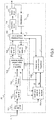
- the figure 3 illustrates a functional diagram of the receiver 20 in the case where the transmitted signal is obtained with an SC-FDMA technique with a CP prefix. It is assumed here that the signal from the transmitter is synchronized to the receiver with an adequate precision (ie less than the duration of the CP, if the latter is present) and that a synchronization algorithm has supplied the synchronization instant to the receiver. The signal supplied as an input to block 101 is therefore already synchronized in time and frequency and at the correct sampling frequency.
- the receiver can be used to receive a signal of the SS-SC-FDMA type.
- the receiver can be used to receive a signal of the SS-SC type.
- the block "CP suppression” is replaced by a block "Extraction of the processing block” which extracts the known sequences (for example to use them to estimate the channel) and the data blocks to be processed, then the receiver can receive signals SC and SS-SC with known pilot sequences in place of CP and CS.
- the receiver is adapted to receive an OFDM or OFDMA type signal.
- the receiver according to the invention contains two feedback loops.
- the first loop is positioned between the DFE equalizer 108 and the flexible SISO 105 demodulator.
- the path of this loop is called “auto-iteration” and an equalizer which uses this loop is an “auto-iterated equalizer”.
- the second loop is located between the flexible SISO demodulator 105 and the “decoding” block decoder 111.
- the path of this loop is designated under the expression “turbo-iteration” and an equalizer which uses this loop is a “ turbo-iterated equalizer ”or a“ turbo-equalizer ”.
- the invention produces an auto-iterated equalizer, of DFE type, which is typically used with information a priori zero at the level of the flexible demodulator.
- the numbers of auto-iterations or turbo-iterations regulate the compromise between performance, computational complexity and necessary memory, within the receiver.
- the input or output parameters of the turbo equalizer, of the equalizer calculation and the parameters of the flexible demodulator, and of the flexible demodulator depend on the id of the current turbo-iteration and possibly the identifier of the current auto-iteration
- the equalizer filter f ( ⁇ , s ) indicates the filter used at turbo-iteration ⁇ and at auto-iteration s . That being said, in the following, to simplify the notation, the apex will not be explained, and we will implicitly refer to the current turbo-iteration and auto-iteration.
- the data blocks After having extracted the data blocks coming from the reception antenna A r of the receiver, by removing the CP in the case of SC systems with CP or from the SC-FDMA, 101, the data blocks pass through a Fast Fourier Transform 102 (FFT) of size N (passage in the frequency domain).
- FFT Fast Fourier Transform
- the signal at the output of the FFT then passes into a “sub-p De-allocate” block 103 which allows access to the M frequency resources (subcarriers) among N, through which the signal was transmitted.
- This block selects only the sub-carriers on which the signal was transmitted (de-allocation of the sub-carriers), and at the output of this last de-allocation block 103 the signal is represented by a vector y of size M, grouping together the sub-carriers used.
- the pilot sequences are extracted from the signals coming from the receiving antenna A r and sent to the “Estimation of channels and noise variance” block 104. They are used to calculate an estimate of the frequency response of the channel. between the sender and the receiver, on the M sub-carriers of interest (those used by the user to send the information).
- the block "Estimation of the channels and of noise variance ”104 also provides an estimate of the noise variance.
- This noise contains the contribution of thermal noise on the receiving antenna A r and possible interference due to several parasitic effects originating either from digital processing or from other external signals.
- the “Estimation of channels and noise variance” block provides the noise covariance matrix in the frequency domain ⁇ w . Typically, there is an estimate of the channel and of the noise covariance per data block.
- a SISO flexible demodulator is activated for an initialization phase.
- the deinterleaver block 110 is not calculated during the initialization phase.
- the a priori information coming from the interleaver block 112 corresponds by convention to a vector of zeros.
- the estimate of the H channel and the estimate of the noise covariance matrix are then transmitted to the “calculation of the equalizer parameters” block 106.
- This block also takes the quantity as input. v from the flexible demapping which measures the average reliability of the symbols sent by the user inside the data block which is being processed (the average is therefore over the block length M in the case of the example) .
- the “calculation of the parameters of the equalizer” block 106 provides as output at each auto-iteration the coefficients of the equalizer f of size M in the frequency domain, which is in general a self-iterated MMSE linear turbo-equalizer with EP feedback. In all cases, the calculation block 106 also outputs an estimate of the noise after equalization.
- f m are the coefficients of the filter f .
- the received signal vector y of size M is passed into the “interference suppression linear equalizer” block 108 which also takes as input the filter coefficients of the equalizer f , the frequency response of the H channel and the size vector M flexible estimates of the symbols emitted in the frequency domain x _ ⁇ , which is generated by the M- size normalized FFT block 107 from the M- size vector of flexible time-domain estimates x , from the flexible SISO 105 demodulator.
- the overall reliability of this estimate is represented by the value v , the closer it is to zero, the greater the reliability ( v is a variance).
- the interference cancellation linear equalizer block 108 performs Interference Cancellation (IC) for the ISI, in this case SISO.
- the interference suppressing linear equalizer block 108 produces a vector of size M x situ which represents an estimate of the symbols in the frequency domain.
- the vector x ⁇ is then passed back into the time domain through a normalized IFFT 109 of size M , to obtain the vector x ⁇ of the equalized temporal signal, which is sent to the SISO flexible demodulator 105.
- the variance of the noise after equalization ⁇ ⁇ 2 and flexible a priori information for example in the form of metrics with a Log-Likelihood Ratio (LLRs) L a coming from the decoder
- the flexible demodulator produces flexible information for each bit of the input signal, for example in the form of extrinsic LLRs L e .
- This demodulator takes different forms depending on the statistic of the signal after equalization: if the starting constellation is real, a demodulator can be used for complex symmetrical Gaussian statistics, otherwise a demodulator for Gaussian statistics with non-zero pseudo-covariance is more suitable.
- the soft metrics are then deinterlaced by the deinterleaver block 110 which is the reverse block of the interleaver block 112. Then, when all the bits of the packet are retrieved, the soft metrics are sent to the decoder 111 which generates, produces bit probability estimates information sent (for example a posteriori probabilities). These probability estimates can be used to obtain a hard estimate b 'of the bits transmitted b with a threshold detector.
- the decoder also produces estimates of the encoded bits sent, i.e. extrinsic probabilities (EXT), for example in the form of LLRs, which measure the probability that the encoded bits sent either 0 or 1.
- EXT extrinsic probabilities
- the interleaver 112 located in the receiver 20 operates in the same way as the interleaver 12 located in the transmitter 10, with the only difference that the latter operates on binary data, while the interleaver 112 operates on LLRs. .
- the interlaced EXTs become a priori information from the point of view of the rest of the receiver, for example in the form of a priori LLRs L a and enter the flexible SISO 105 demodulator.
- the "interference suppression linear equalizer” block 108 performs interference suppression and applies linear frequency equalization to the input signal.
- L-IC Linear Equalizer - Interference Cancellation
- This structure is already well known in the literature [2].
- the difference from the existing state of the art is in the value of the entry x _ ⁇ (estimation of the symbols in the frequency domain) supplied to the block 108, as well as the filter used, these two quantities being calculated in a new way.
- the output x ⁇ of the interference suppression linear equalizer block 108 will therefore be different than that which can be found in [2] on par with the other assumptions.
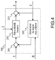
- the figure 4 gives a detailed example for the filtering and interference suppression method, which is efficiently carried out as follows.
- the “interference suppression linear equalizer” block 108 comprises a subtracter 201 which acts on vectors of size M and which subtracts from the signal actually received y, an estimate of this same received signal (useful signal with interference from the propagation channel) .
- This makes it possible to obtain a corrective signal introduced into a linear filter 202 of MMSE type with a frequency response f , calculated by the block for calculating the parameters of the equalizer 106.
- the linear filter 202 is itself followed by an adder 203. of vectors of size M, which reintroduces into the filtered corrective signal the contribution of the useful signal already estimated.
- the block for subtracting the estimated received signal 201 obtains the estimate to be subtracted by a module for generating the estimated received signal (useful signal with interference from the propagation channel) 200.
- the adder 201 implements a cutoff in the frequency domain of the received signal estimated from the received signal, y _ - h _ ⁇ x _ ⁇ The result is called a corrective signal.
- Block 202 simply applies the filter f .
- This is again quite simply an input multiplication by input of the vector of the filter of size M and of the input vector of the same size. This step corresponds to the equalization proper which further reduces the residual ISI of the corrective signal.
- the structure of the SISO 105 flexible demodulator is shown on figure 5 .
- the user chooses the symbols to be sent from among a constellation (potentially multidimensional, here the invention is presented with a constellation with a complex dimension) X ⁇ C , or is the space of complex numbers, of cardinality Q
- , such that q log 2 Q.
- the modulator in the transmitter 10 from each vector of q coded and interlaced bits at the output of the interleaver block 12, generates the corresponding symbol of the constellation according to a function , which is also called function labeling or simply labeling, a concept known to those skilled in the art.
- L at ⁇ d represents the vector of LLRs a priori on the encoded and interlaced bits, coming from the decoder and which are associated with the signal vector estimated after equalization x ⁇ ( ⁇ , s ) being processed.
- L a ( d ) is a vector of zeros (no a priori information on the d bits available).
- the computation chain consisting of a block for computing the prior distributions 300, a block of flexible estimates 301, an average estimator performing an average 302 and a switch 303 is activated.
- This calculation chain is no longer activated for the other indices s ⁇ 0, but only when a new initialization is instructed. During the initialization phase, in normal operation the other blocks are not activated.
- the sent symbols cannot be estimated and they have a variance equal to the statistical power of the original constellation (i.e., the imprecision is maximum).
- switch 303 If s ⁇ 0, switch 303 outputs the estimates of the symbols x ⁇ m ⁇ , s + 1 and their mean variance ⁇ ( ⁇ , s +1) coming from the adaptive smoothing block 307.
- s -1
- the output of the switch 303 therefore corresponds to the output of a flexible mapping with flexible information coming from of the decoder, as described in reference [2].
- the exit L e ⁇ d is not calculated during the initialization phase. Once the outputs of switch 303 are calculated, the input index s is considered to be incremented by 1.
- the figure 5 shows that it is not necessary either to go through the chain comprising the a posteriori LLRs calculation 309, the adder 310 to calculate the extrinsic output LLRs. Indeed, the switch 309 is closed only when that is, when the auto-iterations are complete. According to one variant, it is possible to calculate the LLRs a posteriori for each self-iteration index, in order to be able to start the decoder. We will describe below the processing chain formed by blocks 304, 305, 301, 302, 306, 307 and 303.
- the likelihood calculator block 304 calculates likelihoods from the estimates x ⁇ m ⁇ s (the M equalized symbols of the current block) and the variance of the residual noise after equalization ⁇ ⁇ 2 ⁇ s , using an unbiased Gaussian model for the estimates x ⁇ m ⁇ s . Note that it is described in the state of the art how to use a biased Gaussian model. This calculation gives: L m ⁇ s x ⁇ m ⁇ s
- the block for calculating posterior probability distributions 305 comprises a first block 305A for calculating non-normalized a posteriori probability distributions and a second block 305B having the function of normalizing the values supplied at its input so that the output is a true probability distribution (see Fig. 5 ).
- the block for calculating non-normalized posterior probability distributions 305A calculates the distributions of the symbols emitted by knowing observation (equalized symbols), according to a method known to those skilled in the art: where ⁇ is one of the possible symbols of the constellation X.
- the normalization block 305B normalizes (separately for each index m ) the set of values d m ⁇ s ⁇ , ⁇ ⁇ X so that the output is a probability distribution, according to the following formula:
- the block of flexible estimates 301 calculates the estimates ⁇ m ⁇ s and the mean variance ⁇ ( ⁇ , s ) of the symbols using as input a probability distribution obtained by normalizing (305B, equation (10)) the Gaussian likelihoods obtained by an exact or approximated calculation technique (304).
- the new estimate of the symbols emitted, generated by combining the a priori information available with the information contained in the observation according to the invention has characteristics superior to the a priori estimate. , or an estimate derived from the single observation.
- this operation also makes it possible to project a mixed probabilistic description on the symbols sent (Gaussian variables for the observations, combined with a priori estimates which are categorical variables) on a unique probabilistic description, according to a Gaussian model as described in reference [3].
- the posterior average variance makes it possible both to obtain a more robust estimator of the average reliability of the estimated emitted symbols of the data block and also to be able to implement a equalization strategy in the frequency domain, generally less costly from a computational point of view.
- a posteriori estimates ⁇ m ⁇ s of the symbols emitted and their posterior average variances ⁇ ( ⁇ , s ) are then sent in the “Gaussian division” block 306 which also takes as input the observations (equalized symbols) x ⁇ m ⁇ s and the variance of the residual noise after equalization ⁇ ⁇ 2 ⁇ s which gives a measure of the reliability of these observations.
- the "Gaussian division” using the estimates as means and the reliabilities as variances, associates with each symbol two Gaussian probability density functions, one for the posterior estimates and the other for the observations, divides them between it and them normalizes in order to obtain a third Gaussian probability distribution function having as average a new flexible estimate of the transmitted signal x ⁇ ′ m ⁇ , s + 1 , and as variance the corresponding measure of reliability per data block v ' ( ⁇ , s +1) .
- this block will generate extrinsic information on the symbols emitted, following a Gaussian model.
- the solutions of the state of the art use either a priori information (categorical, extrinsic from the decoder), or a posteriori information (also categorical, combined of the extrinsic information of the decoder and the plausibility of the flexible demodulator).
- This operation therefore makes it possible to better comply with the turbo principle by subtracting from the a posteriori information, the information a priori available to the demodulator at the start of processing (this is the extrinsic of the equalizer) and thus allowing to improve the quality of the return signal and, ultimately, the performance of the receiver.
- ⁇ ⁇ 2 ⁇ s ⁇ ⁇ ⁇ ⁇ s means that the a posteriori information calculated by the flexible SISO demodulator and the information coming from the observations are in mutual contradiction.
- the block 306 can output the information a priori coming from the decoder, calculated at the initialization of the flexible SISO demodulator (not shown on the diagram). figure 5 ), as well as the mean variance associated with the a priori as reliability.
- Still other strategies in the same case consist in fixing the output variance v ' ( ⁇ , s +1) has an arbitrary value prefixed for each ⁇ and s .
- extrinsic estimates are passed to the adaptive smoothing block 307, the purpose of which is to smooth the input estimates by taking into account the past values.
- the z -1 blocks that are on the loop, in the figure 5 represent the unit delay operation, with respect to the index s , with reference to the transform Z.
- the coefficients ⁇ ⁇ , s are always between 0 and 1. When they are close to zero, c ' is the current estimate at the output of the Gaussian division 306 which has more weight, when they are close to one it is the estimates of the previous auto-iteration which have more weight. This filtering is used to increase the robustness of the overall iteration process in the receiver.
- Coefficients ⁇ ⁇ , s close to one give a slow convergence speed, with possible degradations of the final performance, but with more stability. It is therefore possible to adjust the compromise between performance and number of iterations by choosing the filter parameters. In practice there are several choice strategies for these parameters: they are for example constant for all s > 0, ⁇ .
- adaptive filters for example of the Kalman type.
- Yet another method consists in dynamically reading the parameters ⁇ ⁇ , s in a table pre-filled and saved in the memory of the equipment.
- pre-filled values of the parameters ⁇ ⁇ , s can be indexed according to one or more parameters of the receiver (for example the index of the current auto-iteration or of the current turbo-iteration) or d 'one or more metrics that the receiver can measure, such as the estimate of the channel, the estimate of the noise or the reliability of the returns from the decoder for example, and then use their values to dynamically choose the values of the corresponding ⁇ ⁇ , s .
- the adaptive smoothing block 307 generates smoothed extrinsic estimates. x ⁇ m ⁇ , s + 1 of the symbols emitted, as well as for each vector their smoothed average extrinsic variance ⁇ ( ⁇ , s +1) which is a measure of the reliability of the vector of these estimates. These quantities are transmitted to the switch 303, they are considered as outputs of the block 105, if
- the flexible SISO 105 demodulator When executing the SISO 105 soft demodulation, the decoding processing will be started. In this case, the flexible SISO 105 demodulator produces as output, for each new turbo-iteration with the decoder, extrinsic LLRs L e ⁇ d on the coded bits of the processed data block. In this phase, the switch block 308 is closed and only the block 309 and the adder 310 are used. It is not necessary to calculate the other outputs of block 105.
- L e ⁇ d are generated from the a posteriori LLRs calculated by the block 309 and by subtracting the a priori LLRs L at ⁇ d through the sum block 310.
- the figures 6 and 7 illustrate an example of performance of the invention in a case of an SC system with perfect synchronization and channel estimation, in the SISO framework.
- the constellation used by the transmitter is an 8-PSK
- the propagation channel is the Proakis C channel (with average power normalized to one) with a power profile of type triangular (1, 2, 3, 2, 1).
- the figure 6 shows how different instantiations of the invention, called FD -SILE, with for all ⁇ , and with produce better performance than the standard linear MMSE equalizer and the turbo linear frequency MMSE equalizer with IC of [1], referred to in the figures as "FD".
- the figure 6 in particular shows performance with without turbo-iteration, and with by turbo-iterating once with a decoder. In these two cases the gains are considerable.
- figure 7 illustrates performance with turbo-iterations.
- the proposals considered come to approach the terminal of the matched filter better than the linear frequency MMSE turbo-equalizer with IC.
- the method can be applied in different equalizer structures, some examples of which are given below by way of illustration and in no way limiting.
- the invention can be applied to a fractional turbo equalizer see for example [8].
- the signal coming from the antenna is over-sampled with a factor with a factor o > 1, typically integer.
- the data blocks will therefore have a size oN in the FFT 102, oM in the inverse fourrier transform IFFT 109 and in the FFT 107.
- the IFFT block 109 is followed by a flow sampler o and the FFT block 107 is preceded by an ideal interpolator of factor o (which introduces o - 1 zero between two incoming samples).
- the “channel and variance estimate of the noise” block must perform its estimates in the interpolated domain including any transmission and reception filters, and then pass the estimates in frequency if necessary.
- the calculation of the equalizer parameters will perform the filter calculations in the oversampled domain, on the other hand it will estimate the variance of the residual equalization noise at symbol time (to pass it to the flexible demodulator).
- the turbo equalization unit 108 goes therefore work in the oversampled area.
- the SISO flexible demodulation block 105 retains the previous description.
- the invention can be applied to an Overlap FDE type equalizer [9].
- the data block between two pilot sequences is longer than the processing block, and for reasons of complexity or necessity (for example a time-varying channel which changes in the horizon of a block data), the frequency equalization processing is broken down into several segments (with overlap) of the initial data block. These segments suffer from interference between them. This implies that the noise covariance matrix at the output of "noise channel and variance estimate" block 104 also includes the variance due to interference, which modifies the values of the equalization filter.
- the invention can be applied in both interference rejection [10] and interference suppression [11] strategies.
- the channel and noise variance estimate block 104 can implement channel estimation and noise variance methods by exploiting this information additional.
- the new noise channel and variance estimates can be exploited by the rest of the receiver as described above.
- the proposed technique can also be applied to linear equalizers in the broad sense.
- the invention can be used within any type of iterative receiver being structured as illustrated in Figure 8 .
- an RF front-end 500 which extracts the observation y from the signal, received at the antenna, disturbed by the communication channel, and which supplies it to the channel estimation block 501.
- This estimator extracts from the signal y , the pilot sequences, in order to use one of the estimation techniques, known to those skilled in the art, to obtain parameters characterizing the channel.
- It is assumed to have an “adaptive interference suppression receiver” block 502, capable of providing an estimate x ⁇ x + v modeled according to an additive Gaussian statistical model ( v being the equivalent Gaussian noise added to the useful signal).
- the estimate x ⁇ is obtained thanks to an interference suppression method which, by using a preliminary estimate x ⁇ _ of the transmitted signal x , and an estimate of the parameters of the channel, generates an estimate of the interference and subtracts it from the received signal.
- the invention applies to the level of the flexible demodulator 504, where, for a data block with supposedly white statistics, the expectation propagation technique is used to calculate the values.
- flexible estimates x which will serve as decision feedback for the receiver, with the variance v characterizing the reliability of these same estimates.
- the flexible demodulator 504 calculates extrinsic binary LLRs on the bits determining the symbols which can be used to estimate the bits transmitted through a hard decision 505, consisting in comparing each binary LLR to zero.
- the flexible I / O binary decoder block 507 is used in conjunction with the flexible demodulator 504, and the adaptive receiver 502, in an appropriately chosen sequencing, to aid in decoding the transmitter information bits. In particular, one could use the two-loop scheduling, described above for the SC-FDMA application. If the code words at the output of the channel encoder have been interleaved by a binary interleaver (see for example transmitter 10 on figure 2 ), then the blocks of interleaver 506 and interleaver 508 are included in an iteration loop between flexible demodulator 504 and decoder 507.
- the estimator 501 can use, from the first auto-iteration of the receiver, the estimate x of the transmitted signal, together with the observation of the y channel, to refine the parameters of the estimated channel, for example with a method of the “least squares” type over the entire data block, instead of using only the pilots.
- the invention relates, in particular, to the technique of estimating the transmitted signal, at the level of the flexible demodulator 504 which works on a model equivalent to an additive Gaussian noise.
- She may be used in any iterative receiver which goes through such a demodulation step and differs from hard demodulators, used among others in conventional decision feedback equalizers, which are subject to error propagation problems.
- the technique considered here is also different from flexible demodulation techniques using an a posteriori estimation of the signal, which do not remove from the estimation of the return signal the information already known by the receiver, thus inducing the receiver to error. by biasing it with its own information.
- the method according to the invention provides an average reliability per data block, which makes it possible to make the receiver less complex and more robust in the face of errors. occasional estimates. Furthermore, the invention applies adaptive smoothing to the estimated signal, in order to provide an additional degree of freedom which makes it possible to calibrate the ratio between the robustness of the performances and the speed of convergence of the receiver towards the limit performances.
- the invention also applies to the single-user single input multiple output (SIMO) case, that is to say to a communications system with a single transmitter and a single receiver using R antennas at reception.
- SIMO single-user single input multiple output
- the invention also applies to the single-user multiple input multiple output (MIMO) case where the single transmitter is provided with several, T u , transmission antennas.
- MIMO multiple input multiple output
- T u 1
- R antennas where R can be equal to one or more.
- U users transmit to the receiver and use the same time and frequency resources.
- the system is represented in figure 9 .
- This type of system is also referred to as a distributed Multiple Input Multiple Output (MIMO) or virtual MIMO system, or simply MIMO. If these users use separate temporal and frequency resources, allowing the receiver to perceive their signals without interference (ie orthogonal), the receiver can treat each of the users as an independent single-user SIMO / SISO system.
- MIMO distributed Multiple Input Multiple Output
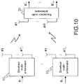
- the invention also applies to a multi-user wireless transmission system, where the users u (10 1 , .. 10 u ) are provided with one or more antennas ( T u ⁇ 1) and the receiver 20 is provided with R antennas or R ⁇ 1.
- T u ⁇ 1 The system is represented in figure 10 .
- This type of system is also called Multi-User MIMO (MU-MIMO) system. If these users use distinct temporal and frequency resources, allowing the receiver to perceive their signals without interference (ie orthogonal), the receiver can treat each of the users as an independent single-user MIMO / MISO (Multiple Input Single Output) system. In this case, only the interference between the signals from the antennas of the same transmitter will be present or not negligible.
- MISO Multiple Input Single Output
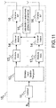
- the figure 11 illustrates the case of a generic 10 u multi-antenna transmitter, and the associated functional block diagram.
- the 11 u error correcting encoder used in this case is not subject to different constraints from those of a single-antenna transmitter, it takes information bits as input, and provides encoded bits at output.
- the space-time interleaver 12 u provides T u stream of independent interlaced bits at output.
- Each of the interlaced bit streams is then modulated by a modulator 13 u, 1 , 13 u, Tu dedicated to each antenna which outputs symbols drawn from a constellation X u, t , which may be different from an antenna to another and from one user to another.
- the correcting code, the interleaver, the modulator and the generation of pilot sequences can have different characteristics chosen according to the user.
- the modulator can have different characteristics chosen as a function of the transmitting antenna for a given user.
- the figure 12 shows a functional block diagram for the receiver in the case where the transmitted signal is obtained with an SC-FDMA technique with CP.
- this receiver can be used in an SC or SS system. -SC or SS-SC-FDMA with CP.
- the receiver is adapted to the different types of SC systems with pilot or constant sequences instead of the CPs. . It is assumed here that the signal from the transmitter is synchronized to the receiver with adequate reliability (ie less than the duration of the CP, if present) and that a synchronization algorithm has supplied the synchronization instant to the receiver.
- the MU-MIMO receiver of the figure 12 contains two feedback loops: an auto-iteration loop (flexible mapper / equalizer iteration) and a turbo-iteration loop (flexible mapper / decoder iteration).
- the receiver in the presence of several users, the receiver must decide, for each loop, the users whose signals will be decoded / processed and which signals will not be decoded / processed.
- the groupings of users in the partition can be done according to several possible metrics, for example users ordered according to the reception power of their signals, or according to a metric derived from the reception power of their signals and the reliability / variance of their constellations, or metrics based on the differences in reception power and reliability between pairs of users, etc.
- the input or output parameters of blocks 106, 108, 105T with the exception of the initial observations y 1 , ..., y R on the various antennas, and the initial estimates H, ⁇ w , depend on the identifier of the current turbo-iteration of the set of users u i to be decoded and possibly of the identifier of the current auto-iteration
- This block has all the T estimated signals as input.
- the receiver therefore tries to decode u i by having the flexible decoding information already for all u j with j ⁇ i.
- a purely parallel user decoding strategy is obtained by setting
- the same mechanism can be used to schedule the decoding of the signals per antenna for all users combined. .
- the quantities exchanged by the iterative receiver of the figure 12 generally depend on the auto-iteration and turbo-iteration index and the ordering of the users to be decoded within a given turbo-iteration (in particular users already decoded within the same turbo-iteration) .
- the turbo-iteration index is incremented when all the users have been decoded (the entire partition of all the users has been scanned according to the established order function).
- the equalizer filter indicates the filter to be applied to equalize the signal of the antenna t of the user u , filter which is used at the turbo-iteration ⁇ and at the auto-iteration s , knowing that during the turbo-iteration we want to decode the users of the set u i and knowing that the users belonging to any u j with j ⁇ i have already been decoded.
- the index of the user u (at the bottom of the symbol) may or may not belong to u i , since it refers to the filter used in the auto-iteration loop (no turbo-iteration), which d 'elsewhere follows a parallel processing method described below.
- the index ( ⁇ , u i , s ) will not necessarily be explained, and we will implicitly refer to the turbo-iteration, to the users currently being decoded. and the current self-iteration.
- this initialization phase must be restarted, which is important in particular for the flexible demapping block 105T, at each new cycle of auto-iterations, which happens for each turbo-iteration ⁇ and, in within it, after each decoding of the users belonging to u i .
- the pilot sequences are extracted from the signals coming from the receiving antenna and sent to the "Channel and noise variance estimate" block 104 and used to calculate an estimate of the frequency response of the MIMO channels between the channels. transmitters and the receiver, on the M sub-carriers of interest (those used by the users to send the information).
- the matrices corresponding to a transmission antenna t of a user u can be concatenated in a block-diagonal matrix H t, u of size MR x M.
- the latter can be concatenated sequentially in a block-diagonal matrix H of size MR x MT, the channels of the antennas of the transmitters are concatenated on the same line, for the same receiving antenna.
- the “Noise Channels and Variance Estimation” block 104 also provides an estimate of the noise variance.
- This noise contains the contribution of thermal noise on the receiving antennas and possible interference due to several effects coming either from digital processing or from other external signals. It is assumed that the block "Estimation of the channels and of the noise variance" provides the noise covariance matrix in the frequency domain ⁇ w of size MR x MR. Typically, there is an estimate of the channel and of the noise covariance per data block.
- the estimation of the global MU-MIMO H channel and of the noise covariance matrix are passed to the “calculation of the equalizer parameters” block 106.
- the equalizer calculated by calculating the parameters of the equalizer 106 coincides with a traditional linear MU-MIMO MMSE equalizer implemented in the frequency domain.
- the flexible demodulator MU-MIMO After the phase of initialization, for all the transmission antennas t of these users u , the flexible demodulator MU-MIMO returns the non-zero flexible estimate vector, and ie the average of the variances of the symbols sent to the antenna t of the user u , calculated on the a priori information coming from the decoder.
- the equalizer obtained by the equalizer calculation 106 coincides with a traditional interference erasing linear MMSE turbo-equalizer implemented in the frequency domain (either according to a series strategy or parallel according to the scheduling of the users u decoded during turbo-iteration).
- the equalizer calculation block 106 provides as output at each auto-iteration the coefficients of the equalizers f t, u of size MR in the domain frequency, for the equalization of the signal coming from the antenna t of the user u.
- This filter acts on the observations concatenated y in the frequency domain.
- Let's call ⁇ _ w 2 diag ⁇ _ w the vector of covariances on the diagonal of the noise covariance matrix.
- the signal vectors received on the antennas and transformed into frequency y r of size M are passed to the “interference suppression linear equalizer” block 108 which also receives as input the coefficients of the equalizers F u , for all the users u (which are processed in parallel), the overall frequency response of the MU-MIMO H channel and the vectors of size M of flexible estimates of the symbols emitted in the frequency domain x ⁇ u , _ for all users u , which are generated from vectors of size M of flexible time domain estimates x u , from the flexible MU-MIMO 105T demodulator.
- the LE-IC 108 equalizer performs Interference Suppression (IC) for ISI, MAI and MUI in the general case MU-MIMO.
- Equalizer 108 produces vectors x ⁇ t, u of size M which represent estimates of the symbols of each antenna of each user in the frequency domain.
- the vectors x ⁇ t, u are then passed again in the time domain through T u normalized IFFTs of size M (109), to obtain vectors x ⁇ t, u representing the equalized time signals, which are sent to the flexible demodulator MU- MIMO 105T.
- the latter from x ⁇ t, u , the corresponding variances of the noise after equalization ⁇ ⁇ , t , u 2 and flexible a priori information, for example in the form of metrics Log-Likelihood Ratios (LLRs) L a ( d u ) from the decoders, produces the flexible estimates of the symbols emitted in the time domain x u , for all u users, as well as their corresponding reliabilities v u . If the turbo-iteration loop is activated afterwards, the flexible mapper also produces flexible information for each bit of the signals of the users belonging to , for example in the form of extrinsic LLR L e ( d u ),
- the flexible metrics L e ( d u ) are then deinterlaced by the 110 u blocks for the users Then the soft metrics are sent to the users 111 u decoders which produce estimates of the probabilities of the bits of information sent (for example a posteriori probabilities), if the last turbo-iteration is reached, ie They are used to decide which bits are sent with threshold detectors. Otherwise, users' 111 u decoders also produce estimates of the encoded bits sent i.e. extrinsic probabilities (EXT), for example in the form of LLRs, which measure the probability that the encoded bits sent are 0 and 1.
- EXT extrinsic probabilities
- the EXTs are then sent to the interleavers 112 u users
- the intertwined EXTs of users become a priori information L a ( d u ) and enter the flexible MU-MIMO 105T demodulator.
- the flexible MU-MIMO 105T demodulator processes its inputs and the procedure continues depending on whether an auto-iteration or turbo-iteration is activated.
- the "Interference Suppression Linear Equalizer” block 108 performs Interference Suppression (IC) for ISI, MAI and MUI and equalizes the received signals in the frequency and spatial domain.
- IC Interference Suppression
- the difference compared to the existing state of the art lies in the inputs x ⁇ _ u (estimates of the symbols in the frequency domain for all the users), as well as the filters used, these quantities being calculated according to the method of the invention.
- the figure 14 describes the filtering and interference removal method in detail.
- the concatenation block 204 is simply used to concatenate the vectors of the soft estimates x ⁇ _ u of size MT u in a single vector x ⁇ _ u in size MT.
- the “Generation of estimated received signals” block 205 generates an estimate of the R signals received (useful part plus interference of any type) at the receiver, concatenated in the output vector.
- the separator 206 separates the vector H x ⁇ _ in R vectors of size M, one for each channel of the receptor.
- the latter are subtracted by vector sums 207 from the symbols received in the frequency domain y r .
- the method is here in parallel, in the sense that all the estimates available in the self-iteration loop of the signals of the users are used to generate the signals received. This makes it possible to take into account (through the estimation of the global channel) the influence that users have on each other, and that antennas have on each other.
- the corrective signals at the output of the sums 207 are sent to a bank of linear MMSE filters 208 which apply singularly the same treatment of the SISO case but by using the filters f r, t, u calculated by the block 106, for all u and t . This is done for all receiving antennas.
- the vector sums 211 u generate the frequency estimates (of size T u M ) of the equalized symbols by adding the estimates of the useful signals to the filtered corrective signals coming from the filter banks 208, as a generalization of the sums coming from the block 201 to the SISO case.
- the MU-MIMO 105T flexible demodulator shown in figure 13 consists of U separate flexible MIMO demodulators 105T u , which separately process the equalized signals corresponding to the transmitting antennas of the same user.
- the scheduling and initialization manager 311 ( figure 13 ) activates all flexible MIMO demodulators during auto-iterations thus generating all flexible estimates x u and their corresponding mean reliability v u so that the blocks implementing the functions related to the interference suppression equalization can have estimates of the signals of all the users.
- the scheduling manager configures only the flexible MIMO demodulators of the users. which must be decoded according to the current schedule so that these demodulators calculate the extrinsic LLRs L e ( d u ) to be sent to the decoders of the interested users.
- the manager 311 will trigger the initialization of the flexible MIMO 105T u demodulators according to the chosen strategy (see description above for the MU-MIMO turbo-receiver of figure 12 ).
- the flexible MIMO 105T demodulator u is composed of T u flexible SISO 105 demodulators already described (see figure 5 ) which are all activated at the same time by the command coming from the scheduling and initialization manager 311 ( figure 13 ).
- Each SISO flexible demodulator 105 processes the data vectors which correspond to one of the transmitting antennas of the user u , using its corresponding constellation X t, u .
- the separation block 113 deconcatens the vector ⁇ ⁇ , u 2 of size T u of the variances of the residual noise, in T u values ⁇ ⁇ , t , u 2 to send to demodulators.
- the separation block 114 deconcatenates the vector x ⁇ u representing signals after equalization and suppression of interference of size MT u , into T u vectors x ⁇ t, u to be sent to the demodulators.
- the separation block 115 deconcatenates the vector L a ( d u ) representing the a priori LLRs coming from the decoder of the user u and of size equal to the sum of the length of the packets encoded on the T u antennas of the user , in T u vectors L a ( d t, u ), representing the a priori LLRs of the packet sent on the antenna t of the user u , to be sent to the demodulators.
- the concatenation devices 116, 117, 118 operate inversely to blocks 113, 114, 105, respectively on reliability v t, u , the flexible estimates of the emitted symbols x t, u and the extrinsic LLRs L e ( d t, u ) to form the vectors v u , x u and L e ( d u ).
- a single MIMO 105T flexible demodulator block u is used at the MIMO receiver, and the symbols transmitted are denoted x t, 1 , with the corresponding code word d 1 .
- the invention also applies trivially for those skilled in the art to diagrams with space-time block codes of the orthogonal type, such as that of Alamouti and described for the case SC-FDMA in the article [12]. , for example. These diagrams are not shown.
- space-time block codes of the orthogonal type there are detection methods known to those skilled in the art [12] with maximum likelihood or maximum a posteriori probability with reduced complexity.
- the invention described here can be applied after having adapted the calculations of the linear equalization block with interference suppression 502 and the block for calculating the parameters of the receiver 503, for example as described in [12] so as to take into account counts the structure of the space-time code by blocks of orthogonal type used at the transmitter.
Landscapes
- Engineering & Computer Science (AREA)
- Power Engineering (AREA)
- Computer Networks & Wireless Communication (AREA)
- Signal Processing (AREA)
- Physics & Mathematics (AREA)
- Probability & Statistics with Applications (AREA)
- Radio Transmission System (AREA)
Claims (23)
- Verfahren zum Verbessern der Schätzung von Symbolen eines modulierten Signals und der Zuverlässigkeit der Schätzung, wobei das Signal einen oder mehrere Datenblöcke umfasst, das wenigstens die folgenden an einem Prozessor durchgeführten Schritte beinhaltet:• einen Schritt des Berechnens von flexiblen Schätzungen (301) des Signals, bei dem die geschätzten Symbole


γ (τ,s) (302) gekennzeichnet sind,• einen Schritt des Gaußschen Dividierens (306) des geschätzten Signals
v ' (τ,s+1) mit:
 • einen Schritt des adaptiven Glättens (307) auf dem geschätzten Signal durch die Gaußsche Division und auf den Zuverlässigkeitsmaßen, zum Liefern einer Schätzung
x (τ,s+1) des übertragenen Signals und eines assoziierten Zuverlässigkeitsmaßesv (τ,s+1). - Verfahren nach Anspruch 1, dadurch gekennzeichnet, dass eine flexible Schätzung des übertragenen Signals

v ' (τ,s+1) berechnet werden:

- Verfahren nach einem der Ansprüche 1 bis 2, das ferner Folgendes beinhaltet:• einen Schritt des Berechnens von A-priori-Verteilungen des übertragenen Signals (300) auf der Basis von binären flexiblen Eingängen/Ausgängen,• einen Schritt des Berechnens von flexiblen Schätzungen (301) des übertragenen Signals anhand der A-posteriori-Wahrscheinlichkeitsverteilungen (305A) am Eingang, berechnet auf der Basis der Gaußschen Likelihoods des geschätzten Signals x̂ (τ,s) (304) und der im vorherigen Schritt (300) berechneten A-priori-Verteilungen, wobei die Schätzung durch ein mittleres Zuverlässigkeitsmaß
γ (τ,s) (302) gekennzeichnet ist. - Verfahren nach einem der Ansprüche 1 bis 3, dadurch gekennzeichnet, dass es ferner Folgendes beinhaltet:• einen Schritt des Decodierens durch einen Decoder mit flexiblen Eingängen/Ausgängen (111),• einen Schritt des Initialisierens des flexiblen Demodulators (105) durch Berechnen einer A-priori-Schätzung
x (τ,0) des übertragenen Signals (300, 301), wobei die Schätzung durch eine mittlere Zuverlässigkeitv (τ,0) (302) gekennzeichnet ist,• wobei die Werte der A-priori-Schätzung und der berechneten mittleren Zuverlässigkeit Ausgangswerte repräsentieren und/oder zum Initialisieren des Schrittes des adaptiven Glättens benutzt werden. - Verfahren nach Anspruch 4, das ferner einen Schritt des Entschachtelns (110, 506) und Verschachtelns (112, 508) flexibler Informationen an dem übertragenen Signal während des iterativen Austauschs zwischen einem flexiblen Demodulator (105, 504) und einem binären Decoder mit flexiblen Eingängen/Ausgängen (111, 507) beinhaltet.
- Verfahren nach einem der Ansprüche 1 bis 5 zum Unterdrücken von Störungen im Inneren eines Signals von wenigstens einem Sender, empfangen an einem Empfänger mit einer oder mehreren Antennen, wobei das Signal einen oder mehrere Datenblöcke umfasst, dadurch gekennzeichnet, dass es ferner die folgenden Schritte beinhaltet:• einen Schritt des Berechnens von Parametern des Empfängers (503) unter Nutzung der Kenntnis des Kanals,• einen Schritt des Verarbeitens des empfangenen Signals durch einen Empfänger mit Störunterdrückung (502), der eine andere Schätzung x̂ (τ,s) des übertragenen Signals unter Nutzung einer Vorabschätzung
x (τ,s+1) des übertragenen Signals x und der Kenntnis des Kanals erzeugt, wobei die Schätzung des Signals durch den Empfänger mit Störunterdrückung erfolgt,• Berechnen der Zuverlässigkeit • einen Schritt des iterativen Austauschens von Schätzungen des übertragenen Signals zwischen dem Empfänger mit Störunterdrückung (502) und dem flexiblen Demodulator (504, 105),• einen Schritt des Berechnens flexibler Informationen an den Bits des übertragenen Signals, durchgeführt auf der Basis des demodulierten Signals (309, 310).
 - Verfahren zur Störunterdrückung eines empfangenen Signals nach Anspruch 6, das ferner Folgendes beinhaltet:• einen Schritt des Berechnens von Parametern des adaptiven Empfängers (503) unter Nutzung der Kenntnis des Kanals und der Zuverlässigkeit der flexiblen Rückläufe des Demodulators (504),• einen Schritt des iterativen Austauschens der Zuverlässigkeiten der Schätzungen des übertragenen Signals zwischen dem Block, der die Parameter des adaptiven Empfängers (503) berechnet, und dem flexiblen Demodulator (504, 105).
- Verfahren zur Störunterdrückung eines empfangenen Signals nach Anspruch 6, das Folgendes beinhaltet:• einen Schritt des Schätzens der Parameter des Kanals zwischen dem Sender und dem Empfänger (501) mittels des empfangenen Signals,• einen Schritt des Berechnens der Parameter des adaptiven Empfängers oder nicht (503) mittels der Schätzung der Parameter des Kanals und der Zuverlässigkeit der flexiblen Rückläufe des Demodulators (504),• einen iterativen Schritt des Austauschens der Zuverlässigkeiten der Schätzungen des übertragenen Signals zwischen dem Block, der die Parameter des adaptiven Empfängers (503) berechnet, und dem flexiblen Demodulator (504, 105).
- Verfahren zum Unterdrücken von Störungen eines empfangenen Signals nach Anspruch 8, das ferner einen iterativen Schritt des Schätzens der Parameter des Kanals (501) unter Nutzung der flexiblen Schätzung des übertragenen Signals und seiner Zuverlässigkeit vom flexiblen Demodulator (504, 105) gemeinsam mit dem empfangenen Signal beinhaltet.
- Verfahren zum Unterdrücken von Störungen eines empfangenen Signals nach einem der Ansprüche 6 bis 9, bei dem der Schritt des Verarbeitens des empfangenen Signals durch einen Empfänger mit Störunterdrückung (502) und der Schritt des Berechnens seiner Parameter (503) Folgendes beinhalten:• einen Schritt des Umwandelns des empfangenen Signals in die Frequenzdomäne (102),• einen Schritt des Berechnens der Parameter des Entzerrers in der Frequenzdomäne (106), der die Funktionen des Blocks (503) realisiert,• einen Schritt des linearen Entzerrens mit Störunterdrückung (108) in der Frequenzdomäne, parametrisiert gemäß den beim Berechnen der Parameter des Entzerrers in der Frequenzdomäne (106) erhaltenen Ausgänge,• einen Schritt des Umwandelns des verarbeiteten Signals in die Zeitdomäne (109),• einen Schritt des Umwandelns, in der Frequenzdomäne (107), der flexiblen Schätzung des von dem flexiblen Demodulators gelieferten übertragenen Signals.
- Verfahren nach einem der Ansprüche 6 bis 9, bei dem der Schritt des Verarbeitens des empfangenen Signals durch einen Empfänger mit Störunterdrückung (502) und der Schritt des Berechnens seiner Parameter (503) Folgendes beinhalten:• einen Schritt des Trennens des empfangenen Signals y in P Segmente yp von Np Symbolen, mit Überlappung, p = 1, ..., P,• einen Schritt des Umwandelns jedes der Segmente des empfangenen Signals in die Frequenzdomäne (102),• einen Schritt des Berechnens der Parameter von P Entzerrern in der Frequenzdomäne, der die Funktionen des Blocks (503) realisiert,• einen Schritt des linearen Entzerrens mit Störunterdrückung (108) in der Frequenzdomäne von jedem der Segmente, parametrisiert gemäß den bei der Berechnung der Parameter von P Entzerrern in der Frequenzdomäne (503) erhaltenen Ausgänge,• einen Schritt des Umwandelns jedes der verarbeiteten Signale in die Zeitdomäne (109), und des Extrahierens der nicht überlappten Symbole zum Erhalten einer Schätzung x̂ (τ,s),• einen Schritt des Umwandelns der flexiblen Schätzung des vom flexiblen Demodulator gelieferten übertragenen Signals in die Frequenzdomäne (107).
- Verfahren nach Anspruch 11, bei dem das Berechnen der Parameter der P Entzerrer in der Frequenzdomäne die Kenntnis der Statistik der Störung zwischen Segmenten nutzt, geschätzt auf der Basis der Zuverlässigkeit der Rückläufe des flexiblen Demodulators (504).
- Verfahren nach Anspruch 11 oder 12, bei dem die Reststörung zwischen Segmenten unter Nutzung der Rückläufe des flexiblen Demodulators (504) regeneriert und von jedem der P Segmente yp subtrahiert wird, vor dem Schritt des Umwandelns in die Frequenzdomäne.
- Verfahren nach einem der Ansprüche 6 bis 9, bei dem der Schritt des Verarbeitens des empfangenen Signals durch einen Empfänger mit Rauschunterdrückung (502) und der Schritt des Berechnens seiner Parameter (503) Folgendes beinhalten:• eine Überabtastung des empfangenen Signals mit einem Überabtastfaktor o,• einen Schritt des Frequenzumwandelns (102) des überabgetasteten empfangenen Signals,• einen Schritt des Berechnens des Filters des Entzerrers in der überabgetasteten Frequenzdomäne,• einen Schritt des linearen Entzerrens mit Störunterdrückung (108) in der überabgetasteten Frequenzdomäne gemäß dem beim Berechnen der Parameter des Entzerrers in der überabgetasteten Frequenzdomäne (503) erhaltenen Ausgang,• einen Schritt des Umwandelns des verarbeiteten Signals in die Zeitdomäne (109), gefolgt von einem Abtaster mit einem Abtastfaktor o gleich dem Überabtastfaktor des empfangenen Signals,• einen Schritt des idealen Interpolierens der flexiblen Schätzung des von dem flexiblen Demodulator gelieferten übertragenen Signals mit einem Überabtastfaktor o gleich dem des empfangenen Signals (das im Hinzufügen von o - 1 Nullen zwischen zwei Abtastungen besteht), gefolgt von einer Umwandlung in die überabgetastete Frequenzdomäne (107).
- Verfahren zum Unterdrücken von Störungen im Inneren eines auf einem SC-FDMA- oder SS-SC-FDMA-Empfänger empfangenen Signals, das einen Schritt des Rasterns jeweils mittels einer SC-FDMA- oder SS-SC-FDMA-Modulation und einen Schritt des Ausführens des Verfahrens nach einem der Ansprüche 10 bis 14 beinhaltet.
- Verfahren zum Unterdrücken von Störungen im Inneren eines empfangenen Signals auf einem SC- oder SS-SC-Empfänger, das einen Schritt des Rasterns jeweils unter Nutzung einer SC- oder SS-SC-Modulation und einen Schritt des Ausführens des Verfahrens nach einem der Ansprüche 10 bis 14 beinhaltet.
- Verfahren zum Unterdrücken von Störungen im Inneren eines auf einem OFDM- oder OFDMA-Empfänger empfangenen Signals, das einen Schritt des Rasterns jeweils unter Nutzung einer OFDM- oder OFDMA-Modulation und einen Schritt des Ausführens des Verfahrens nach einem der Ansprüche 6 bis 9 beinhaltet, wobei der Schritt des Verarbeitens des durch einen Empfänger mit Störunterdrückung (502) empfangenen Signals und der Schritt des Berechnens seiner Parameter (503) Folgendes beinhalten:• einen Schritt des Umwandelns des empfangenen Signals in die Frequenzdomäne (102),• einen Schritt des Berechnens der Parameter des Entzerrers in der Frequenzdomäne (106), der die Funktionen des Blocks (503) realisiert,• einen Schritt des linearen Entzerrens mit Störunterdrückung (108) in der Frequenzdomäne, parametrisiert gemäß den beim Berechnen der Parameter des Entzerrers in der Frequenzdomäne (106) erhaltenen Ausgängen.
- Verfahren zum Unterdrücken von Störungen eines empfangenen Signals nach einem der Ansprüche 10 bis 17, das ferner Folgendes beinhaltet:• einen Schritt des Erzeugens des Signals am Sender gemäß einem Raum-Zeit-Blockcode des Alamouti-Typs oder einem anderen Raum-Zeit-Blockcode des orthogonalen Typs,• einen Schritt des Schätzens der Parameter der Kanäle zwischen den Antennen des Senders und denen des Empfängers,• einen Schritt des Berechnens der Parameter des Empfängers in der Frequenzdomäne, der die Struktur des benutzten Raum-Zeit-Blockcodes berücksichtigt,• einen Schritt des linearen Entzerrens mit Störunterdrückung in der Frequenzdomäne mittels der beim Berechnen der Parameter der Entzerrer in der Frequenzdomäne erhaltenen Filter, und der die am Eingang empfangenen Signale mit einem Verfahren kombiniert, das mit dem vom Sender benutzten Raum-Zeit-Blockcode assoziiert ist.
- Verfahren zum Unterdrücken von Störungen im Inneren von an einem Empfänger empfangenen Signale eines Senders in einem Netzwerk des MIMO-Typs, in dem der Sender mit mehreren Sendeantennen und einem Verschachteler ausgestattet ist, der die codierten Bits auf die verfügbaren Antennen verteilt, das einen Schritt des Ausführens des Verfahrens nach einem der Ansprüche 6 bis 17 beinhaltet, der ferner Folgendes beinhaltet:• einen Schritt des Verarbeitens der empfangenen Signale von Antennen des Senders durch einen Empfänger mit Störunterdrückung (502), der unter Nutzung seiner Parameter und einer Vorabschätzung der übertragenen Signale
x t,1 durch die Sendeantennen t = 1, ..., T 1 des Benutzers eine andere Schätzung der gesendeten Signale x̂ t,1 (207-211, 205) erzeugt,• einen Schritt des Berechnens der Parameter des Empfängers (503), der die Anwesenheit mehrerer Sendeantennen und der Schätzungen der Parameter der Kanäle zwischen den Antennen des Senders und des Empfängers berücksichtigt,• einen Schritt des flexiblen Demodulierens (105Tu), in dem die Schätzung des Signals jeder Sendeantenne unabhängig verarbeitet wird. - Verfahren zum Unterdrücken von Störungen im Inneren von an einem Empfänger empfangenen Signalen von mehreren Sendern in einem Netzwerk des MU-MIMO-Typs, in dem die Sender mit mehreren Sendeantennen und einem Verschachteler ausgestattet sind, der die codierten Bits auf die verfügbaren Antennen verteilt, das einen Schritt des Ausführens des Verfahrens nach einem der Ansprüche 6 bis 17 beinhaltet, der Folgendes beinhaltet:• einen Schritt des Verarbeitens von empfangenen Signalen von Sendern durch einen Empfänger mit Störunterdrückung (502), der anhand seiner Parameter und einer Vorabschätzung der übertragenen Signale
x t,u durch die Sendeantennen t = 1, ..., Tu der Benutzer 1, ..., U eine andere Schätzung der gesendeten Signale x̂ t,u (204-211) erzeugt,• einen Schritt des Berechnens der Parameter des Empfängers, der die Anwesenheit mehrerer Benutzer berücksichtigt, eventuell mit mehreren Sendeantennen, und von mehreren Schätzungen der Parameter der Kanäle zwischen den Antennen der Sender und des Empfängers,• einen Schritt des flexiblen Demodulierens (105T), bei dem die Schätzung des Signals jeder Sendeantenne jedes Benutzers unabhängig verarbeitet wird,• einen Schritt des Planens (311) der zu decodierenden Benutzer gemäß einem Kriterium auf der Basis der Leistung der empfangenen Signale oder gemäß einer Metrik, die von der Leistung der empfangenen Signale und der Zuverlässigkeit ihrer Konstellationen abgeleitet wird, oder auch gemäß einer Metrik auf der Basis der Leistungs- Zuverlässigkeitsabweichungen zwischen Benutzerpaaren. - Empfänger, der wenigstens eine Antenne zum Empfangen eines von wenigstens einem Sender gesendeten Signals umfasst, dadurch gekennzeichnet, dass er wenigstens Folgendes umfasst:• einen Prozessor, konfiguriert zum Ausführen des Verfahrens zum Verbessern der Berechnung der Symbole und ihrer Zuverlässigkeiten nach einem der Ansprüche 1 bis 20, wobei die Symbole für die Modulation eines Signals benutzt werden,• ein Modul zum Berechnen von Gaußschen Likelihoods (304) mit einem Ausgang, der mit einem Normalisierungsblock (305B) verbunden ist, dessen Ausgang mit einem zweiten Modul von flexiblen Schätzungen (301) verbunden ist,• ein zweites Modul von flexiblen Schätzungen (301), das seine Schätzungen


γ (τ,s) mit dem Gaußschen Divisionsmodul verbunden ist,• ein adaptives Glättungsmodul (307), das mit dem Gaußschen Divisionsmodul verbunden ist und die geglätteten flexiblen Schätzungenx (τ,s+1) sowie deren Varianzenv (τ,s+1) liefert. - Empfänger nach Anspruch 21, dadurch gekennzeichnet, dass er einen flexiblen Demodulator umfasst, der wenigstens die folgenden Elemente umfasst:• ein Modul (300) zum Berechnen von A-priori-Verteilungen mit einem Eingang von A-priori-Likelihood-Verhältnissen LLR und mit einem Ausgang, der mit einem Modul zum Berechnen von A-posteriori-Verteilungen (305A) und einem Modul zum Berechnen von flexiblen Schätzungen (301) verbunden ist,• ein zweites Modul (301) zum Berechnen von flexiblen Schätzungen, das flexible A-priori-Schätzungen
x (τ,0) liefert, gekennzeichnet durch eine mittlere Zuverlässigkeitv (τ,0) (302). - Empfänger nach Anspruch 21 oder 22, dadurch gekennzeichnet, dass er Folgendes umfasst:
ein Auswahlmodul (303), konfiguriert zum Auswählen der flexiblen A-priori-Schätzungenx (τ,0) und deren Varianz, oder der geglätteten flexiblen Schätzungenx (τ,s+1) und deren Varianz je nachdem, ob es sich um die erste Ausführung (Initialisierungsausführung) des flexiblen Demodulators handelt oder nicht, die am Eingang des flexiblen Demodulators die Werte der A-priori-Likelihood-Verhältnisse LLR entsprechend den flexiblen A-priori-Schätzungenx (τ,0) hat.
Priority Applications (1)
| Application Number | Priority Date | Filing Date | Title |
|---|---|---|---|
| PL19156763T PL3528443T3 (pl) | 2018-02-15 | 2019-02-12 | Sposób obliczania estymacji modulowanego sygnału cyfrowego i jego niezawodności |
Applications Claiming Priority (1)
| Application Number | Priority Date | Filing Date | Title |
|---|---|---|---|
| FR1800146A FR3077941A1 (fr) | 2018-02-15 | 2018-02-15 | Procede pour calculer une estimation d'un signal numerique module et de sa fiabilite |
Publications (2)
| Publication Number | Publication Date |
|---|---|
| EP3528443A1 EP3528443A1 (de) | 2019-08-21 |
| EP3528443B1 true EP3528443B1 (de) | 2020-09-09 |
Family
ID=62167449
Family Applications (1)
| Application Number | Title | Priority Date | Filing Date |
|---|---|---|---|
| EP19156763.5A Active EP3528443B1 (de) | 2018-02-15 | 2019-02-12 | Verfahren zum berechnen eines schätzwerts eines modulierten digitalen signals und seiner zuverlässigkeit |
Country Status (4)
| Country | Link |
|---|---|
| EP (1) | EP3528443B1 (de) |
| ES (1) | ES2833540T3 (de) |
| FR (1) | FR3077941A1 (de) |
| PL (1) | PL3528443T3 (de) |
Cited By (1)
| Publication number | Priority date | Publication date | Assignee | Title |
|---|---|---|---|---|
| FR3157999A1 (fr) * | 2023-12-28 | 2025-07-04 | Thales | Procédé de calcul d'une table de correspondance entre une variance d'échantillons d'entrée d'un démodulateur souple et une variance associée à des LLR bits a priori dans un récepteur turbo |
Families Citing this family (6)
| Publication number | Priority date | Publication date | Assignee | Title |
|---|---|---|---|---|
| CN112104580B (zh) * | 2020-09-11 | 2023-07-21 | 中海石油(中国)有限公司湛江分公司 | 基于广义近似消息传递-稀疏贝叶斯学习的稀疏水声信道估计方法 |
| CN115167391B (zh) * | 2022-06-14 | 2024-10-15 | 北京交通大学 | 一种基于滑模控制的虚拟编组列车编队控制方法 |
| FR3157997A1 (fr) | 2023-12-28 | 2025-07-04 | Thales | Procédé d'estimation d'un signal de retour souple dans un récepteur turbo basé sur la propagation d'espérance |
| FR3157998A1 (fr) | 2023-12-28 | 2025-07-04 | Thales | Procédé de calcul d'une table de correspondance permettant la mise en oeuvre efficace d'un modulateur souple dans un récepteur turbo |
| CN121367478B (zh) * | 2025-12-22 | 2026-03-17 | 苏州大学 | 量化感知宽线性最小误差模自适应滤波器 |
| CN121508553B (zh) * | 2026-01-14 | 2026-04-10 | 电子科技大学 | 一种基于干扰抑制的Hadamard-LDPC迭代译码方法 |
-
2018
- 2018-02-15 FR FR1800146A patent/FR3077941A1/fr not_active Withdrawn
-
2019
- 2019-02-12 PL PL19156763T patent/PL3528443T3/pl unknown
- 2019-02-12 EP EP19156763.5A patent/EP3528443B1/de active Active
- 2019-02-12 ES ES19156763T patent/ES2833540T3/es active Active
Non-Patent Citations (1)
| Title |
|---|
| None * |
Cited By (1)
| Publication number | Priority date | Publication date | Assignee | Title |
|---|---|---|---|---|
| FR3157999A1 (fr) * | 2023-12-28 | 2025-07-04 | Thales | Procédé de calcul d'une table de correspondance entre une variance d'échantillons d'entrée d'un démodulateur souple et une variance associée à des LLR bits a priori dans un récepteur turbo |
Also Published As
| Publication number | Publication date |
|---|---|
| ES2833540T3 (es) | 2021-06-15 |
| PL3528443T3 (pl) | 2021-03-08 |
| EP3528443A1 (de) | 2019-08-21 |
| FR3077941A1 (fr) | 2019-08-16 |
Similar Documents
| Publication | Publication Date | Title |
|---|---|---|
| EP3528443B1 (de) | Verfahren zum berechnen eines schätzwerts eines modulierten digitalen signals und seiner zuverlässigkeit | |
| EP2947799B1 (de) | Verfahren zur im weiteren sinne linearen turboentzerrung in einem system mit mehreren nutzern und für einen mehrantennen-empfänger | |
| EP2220803B1 (de) | Störminderung bei einem ofdm-signal mit gewichtungsvektorbildung in untervektorräumen | |
| EP1658694B1 (de) | Iteratives decodierungs- und entzerrungsverfahren und vorrichtung für kommunikation mit mehreren sende- und empfangsantennen | |
| EP3800813B1 (de) | Verfahren und vorrichtung zur vorhersage der leistungen eines empfängers in einem kommunikationssystem | |
| EP2274852A2 (de) | Verfahren zur dekodierung eines signals mit progressivem aufbau eines dekodierbaums, entsprechendes computerprogrammprodukt und dekodiergerät | |
| EP1589685B1 (de) | Iterative Chipentzerrung und Mehrbenutzerdetektion in CDMA Kommunikationssystemen durch MIMO Kanal | |
| EP1603264B1 (de) | Verfahren und Gerät zum Empfang von einem linear vorkodierten und kanalkodierten Signal | |
| FR2893433A1 (fr) | Procedes et dispositifs de demodulation souple dans un systeme ofdm-cdma. | |
| EP1589672B1 (de) | Iterative Vektoregalisierungsverfahren für CDMA-Kommunikationssysteme über MIMO-Kanal | |
| WO2005029757A1 (fr) | Recepteur et procede de decodage d’un signal code a l’aide d’une matrice de codage espace-temps | |
| EP1856871A1 (de) | Verfahren für den wiederholten empfang eines mehrträgersignals mit interferenzunterdrückung, entsprechender empfänger und computerprogramm | |
| EP1589673B1 (de) | Iterative Mehrbenutzerdetektionsverfahren für CDMA-Kommunikationssysteme über MIMO-Kanal | |
| EP1221206B1 (de) | Verfahren und vorrichtung zur demodulation von mehrebenutzersignalen | |
| EP1999918B1 (de) | Verfahren und Einrichtung zum Empfangen eines aus Symbolblöcken bestehenden Datensignals und entsprechendes Computerprogramm | |
| FR2849306A1 (fr) | Recepteur a turbo-estimation de canal a convergence optimisee | |
| WO2023213962A1 (en) | Continuous phase modulation receiver | |
| CA2389592A1 (fr) | Procede et dispositif pour ordonner des signaux provenant de multi-utilisateurs | |
| WO2016020611A1 (fr) | Procede et dispositif de reception de signaux | |
| FR2889383A1 (fr) | Procede et dispositif de detection pour systeme mimo, systeme mimo, programme et support d'information |
Legal Events
| Date | Code | Title | Description |
|---|---|---|---|
| PUAI | Public reference made under article 153(3) epc to a published international application that has entered the european phase |
Free format text: ORIGINAL CODE: 0009012 |
|
| STAA | Information on the status of an ep patent application or granted ep patent |
Free format text: STATUS: THE APPLICATION HAS BEEN PUBLISHED |
|
| AK | Designated contracting states |
Kind code of ref document: A1 Designated state(s): AL AT BE BG CH CY CZ DE DK EE ES FI FR GB GR HR HU IE IS IT LI LT LU LV MC MK MT NL NO PL PT RO RS SE SI SK SM TR |
|
| AX | Request for extension of the european patent |
Extension state: BA ME |
|
| STAA | Information on the status of an ep patent application or granted ep patent |
Free format text: STATUS: REQUEST FOR EXAMINATION WAS MADE |
|
| 17P | Request for examination filed |
Effective date: 20200217 |
|
| GRAP | Despatch of communication of intention to grant a patent |
Free format text: ORIGINAL CODE: EPIDOSNIGR1 |
|
| RBV | Designated contracting states (corrected) |
Designated state(s): AL AT BE BG CH CY CZ DE DK EE ES FI FR GB GR HR HU IE IS IT LI LT LU LV MC MK MT NL NO PL PT RO RS SE SI SK SM TR |
|
| STAA | Information on the status of an ep patent application or granted ep patent |
Free format text: STATUS: GRANT OF PATENT IS INTENDED |
|
| RIC1 | Information provided on ipc code assigned before grant |
Ipc: H04L 25/06 20060101ALI20200306BHEP Ipc: H04L 25/03 20060101AFI20200306BHEP |
|
| INTG | Intention to grant announced |
Effective date: 20200326 |
|
| GRAS | Grant fee paid |
Free format text: ORIGINAL CODE: EPIDOSNIGR3 |
|
| GRAA | (expected) grant |
Free format text: ORIGINAL CODE: 0009210 |
|
| STAA | Information on the status of an ep patent application or granted ep patent |
Free format text: STATUS: THE PATENT HAS BEEN GRANTED |
|
| AK | Designated contracting states |
Kind code of ref document: B1 Designated state(s): AL AT BE BG CH CY CZ DE DK EE ES FI FR GB GR HR HU IE IS IT LI LT LU LV MC MK MT NL NO PL PT RO RS SE SI SK SM TR |
|
| REG | Reference to a national code |
Ref country code: GB Ref legal event code: FG4D Free format text: NOT ENGLISH |
|
| REG | Reference to a national code |
Ref country code: AT Ref legal event code: REF Ref document number: 1312960 Country of ref document: AT Kind code of ref document: T Effective date: 20200915 Ref country code: CH Ref legal event code: EP |
|
| REG | Reference to a national code |
Ref country code: DE Ref legal event code: R096 Ref document number: 602019000579 Country of ref document: DE |
|
| REG | Reference to a national code |
Ref country code: IE Ref legal event code: FG4D Free format text: LANGUAGE OF EP DOCUMENT: FRENCH |
|
| REG | Reference to a national code |
Ref country code: FI Ref legal event code: FGE |
|
| REG | Reference to a national code |
Ref country code: LT Ref legal event code: MG4D |
|
| PG25 | Lapsed in a contracting state [announced via postgrant information from national office to epo] |
Ref country code: GR Free format text: LAPSE BECAUSE OF FAILURE TO SUBMIT A TRANSLATION OF THE DESCRIPTION OR TO PAY THE FEE WITHIN THE PRESCRIBED TIME-LIMIT Effective date: 20201210 Ref country code: LT Free format text: LAPSE BECAUSE OF FAILURE TO SUBMIT A TRANSLATION OF THE DESCRIPTION OR TO PAY THE FEE WITHIN THE PRESCRIBED TIME-LIMIT Effective date: 20200909 Ref country code: BG Free format text: LAPSE BECAUSE OF FAILURE TO SUBMIT A TRANSLATION OF THE DESCRIPTION OR TO PAY THE FEE WITHIN THE PRESCRIBED TIME-LIMIT Effective date: 20201209 Ref country code: NO Free format text: LAPSE BECAUSE OF FAILURE TO SUBMIT A TRANSLATION OF THE DESCRIPTION OR TO PAY THE FEE WITHIN THE PRESCRIBED TIME-LIMIT Effective date: 20201209 Ref country code: HR Free format text: LAPSE BECAUSE OF FAILURE TO SUBMIT A TRANSLATION OF THE DESCRIPTION OR TO PAY THE FEE WITHIN THE PRESCRIBED TIME-LIMIT Effective date: 20200909 Ref country code: SE Free format text: LAPSE BECAUSE OF FAILURE TO SUBMIT A TRANSLATION OF THE DESCRIPTION OR TO PAY THE FEE WITHIN THE PRESCRIBED TIME-LIMIT Effective date: 20200909 |
|
| REG | Reference to a national code |
Ref country code: AT Ref legal event code: MK05 Ref document number: 1312960 Country of ref document: AT Kind code of ref document: T Effective date: 20200909 |
|
| REG | Reference to a national code |
Ref country code: NL Ref legal event code: MP Effective date: 20200909 |
|
| PG25 | Lapsed in a contracting state [announced via postgrant information from national office to epo] |
Ref country code: LV Free format text: LAPSE BECAUSE OF FAILURE TO SUBMIT A TRANSLATION OF THE DESCRIPTION OR TO PAY THE FEE WITHIN THE PRESCRIBED TIME-LIMIT Effective date: 20200909 Ref country code: RS Free format text: LAPSE BECAUSE OF FAILURE TO SUBMIT A TRANSLATION OF THE DESCRIPTION OR TO PAY THE FEE WITHIN THE PRESCRIBED TIME-LIMIT Effective date: 20200909 |
|
| PG25 | Lapsed in a contracting state [announced via postgrant information from national office to epo] |
Ref country code: EE Free format text: LAPSE BECAUSE OF FAILURE TO SUBMIT A TRANSLATION OF THE DESCRIPTION OR TO PAY THE FEE WITHIN THE PRESCRIBED TIME-LIMIT Effective date: 20200909 Ref country code: PT Free format text: LAPSE BECAUSE OF FAILURE TO SUBMIT A TRANSLATION OF THE DESCRIPTION OR TO PAY THE FEE WITHIN THE PRESCRIBED TIME-LIMIT Effective date: 20210111 Ref country code: RO Free format text: LAPSE BECAUSE OF FAILURE TO SUBMIT A TRANSLATION OF THE DESCRIPTION OR TO PAY THE FEE WITHIN THE PRESCRIBED TIME-LIMIT Effective date: 20200909 Ref country code: CZ Free format text: LAPSE BECAUSE OF FAILURE TO SUBMIT A TRANSLATION OF THE DESCRIPTION OR TO PAY THE FEE WITHIN THE PRESCRIBED TIME-LIMIT Effective date: 20200909 Ref country code: SM Free format text: LAPSE BECAUSE OF FAILURE TO SUBMIT A TRANSLATION OF THE DESCRIPTION OR TO PAY THE FEE WITHIN THE PRESCRIBED TIME-LIMIT Effective date: 20200909 |
|
| PG25 | Lapsed in a contracting state [announced via postgrant information from national office to epo] |
Ref country code: AL Free format text: LAPSE BECAUSE OF FAILURE TO SUBMIT A TRANSLATION OF THE DESCRIPTION OR TO PAY THE FEE WITHIN THE PRESCRIBED TIME-LIMIT Effective date: 20200909 Ref country code: AT Free format text: LAPSE BECAUSE OF FAILURE TO SUBMIT A TRANSLATION OF THE DESCRIPTION OR TO PAY THE FEE WITHIN THE PRESCRIBED TIME-LIMIT Effective date: 20200909 Ref country code: IS Free format text: LAPSE BECAUSE OF FAILURE TO SUBMIT A TRANSLATION OF THE DESCRIPTION OR TO PAY THE FEE WITHIN THE PRESCRIBED TIME-LIMIT Effective date: 20210109 |
|
| REG | Reference to a national code |
Ref country code: DE Ref legal event code: R097 Ref document number: 602019000579 Country of ref document: DE |
|
| REG | Reference to a national code |
Ref country code: ES Ref legal event code: FG2A Ref document number: 2833540 Country of ref document: ES Kind code of ref document: T3 Effective date: 20210615 |
|
| PG25 | Lapsed in a contracting state [announced via postgrant information from national office to epo] |
Ref country code: SK Free format text: LAPSE BECAUSE OF FAILURE TO SUBMIT A TRANSLATION OF THE DESCRIPTION OR TO PAY THE FEE WITHIN THE PRESCRIBED TIME-LIMIT Effective date: 20200909 |
|
| PLBE | No opposition filed within time limit |
Free format text: ORIGINAL CODE: 0009261 |
|
| STAA | Information on the status of an ep patent application or granted ep patent |
Free format text: STATUS: NO OPPOSITION FILED WITHIN TIME LIMIT |
|
| 26N | No opposition filed |
Effective date: 20210610 |
|
| PG25 | Lapsed in a contracting state [announced via postgrant information from national office to epo] |
Ref country code: DK Free format text: LAPSE BECAUSE OF FAILURE TO SUBMIT A TRANSLATION OF THE DESCRIPTION OR TO PAY THE FEE WITHIN THE PRESCRIBED TIME-LIMIT Effective date: 20200909 Ref country code: SI Free format text: LAPSE BECAUSE OF FAILURE TO SUBMIT A TRANSLATION OF THE DESCRIPTION OR TO PAY THE FEE WITHIN THE PRESCRIBED TIME-LIMIT Effective date: 20200909 |
|
| PG25 | Lapsed in a contracting state [announced via postgrant information from national office to epo] |
Ref country code: MC Free format text: LAPSE BECAUSE OF FAILURE TO SUBMIT A TRANSLATION OF THE DESCRIPTION OR TO PAY THE FEE WITHIN THE PRESCRIBED TIME-LIMIT Effective date: 20200909 |
|
| REG | Reference to a national code |
Ref country code: BE Ref legal event code: MM Effective date: 20210228 |
|
| PG25 | Lapsed in a contracting state [announced via postgrant information from national office to epo] |
Ref country code: LU Free format text: LAPSE BECAUSE OF NON-PAYMENT OF DUE FEES Effective date: 20210212 |
|
| PG25 | Lapsed in a contracting state [announced via postgrant information from national office to epo] |
Ref country code: IE Free format text: LAPSE BECAUSE OF NON-PAYMENT OF DUE FEES Effective date: 20210212 |
|
| PG25 | Lapsed in a contracting state [announced via postgrant information from national office to epo] |
Ref country code: BE Free format text: LAPSE BECAUSE OF NON-PAYMENT OF DUE FEES Effective date: 20210228 |
|
| REG | Reference to a national code |
Ref country code: CH Ref legal event code: PL |
|
| PG25 | Lapsed in a contracting state [announced via postgrant information from national office to epo] |
Ref country code: LI Free format text: LAPSE BECAUSE OF NON-PAYMENT OF DUE FEES Effective date: 20220228 Ref country code: CH Free format text: LAPSE BECAUSE OF NON-PAYMENT OF DUE FEES Effective date: 20220228 |
|
| PG25 | Lapsed in a contracting state [announced via postgrant information from national office to epo] |
Ref country code: NL Free format text: LAPSE BECAUSE OF NON-PAYMENT OF DUE FEES Effective date: 20200923 Ref country code: CY Free format text: LAPSE BECAUSE OF FAILURE TO SUBMIT A TRANSLATION OF THE DESCRIPTION OR TO PAY THE FEE WITHIN THE PRESCRIBED TIME-LIMIT Effective date: 20200909 |
|
| PG25 | Lapsed in a contracting state [announced via postgrant information from national office to epo] |
Ref country code: HU Free format text: LAPSE BECAUSE OF FAILURE TO SUBMIT A TRANSLATION OF THE DESCRIPTION OR TO PAY THE FEE WITHIN THE PRESCRIBED TIME-LIMIT; INVALID AB INITIO Effective date: 20190212 |
|
| GBPC | Gb: european patent ceased through non-payment of renewal fee |
Effective date: 20230212 |
|
| PG25 | Lapsed in a contracting state [announced via postgrant information from national office to epo] |
Ref country code: GB Free format text: LAPSE BECAUSE OF NON-PAYMENT OF DUE FEES Effective date: 20230212 |
|
| PG25 | Lapsed in a contracting state [announced via postgrant information from national office to epo] |
Ref country code: GB Free format text: LAPSE BECAUSE OF NON-PAYMENT OF DUE FEES Effective date: 20230212 |
|
| PG25 | Lapsed in a contracting state [announced via postgrant information from national office to epo] |
Ref country code: MK Free format text: LAPSE BECAUSE OF FAILURE TO SUBMIT A TRANSLATION OF THE DESCRIPTION OR TO PAY THE FEE WITHIN THE PRESCRIBED TIME-LIMIT Effective date: 20200909 |
|
| PG25 | Lapsed in a contracting state [announced via postgrant information from national office to epo] |
Ref country code: MT Free format text: LAPSE BECAUSE OF FAILURE TO SUBMIT A TRANSLATION OF THE DESCRIPTION OR TO PAY THE FEE WITHIN THE PRESCRIBED TIME-LIMIT Effective date: 20200909 |
|
| PG25 | Lapsed in a contracting state [announced via postgrant information from national office to epo] |
Ref country code: TR Free format text: LAPSE BECAUSE OF FAILURE TO SUBMIT A TRANSLATION OF THE DESCRIPTION OR TO PAY THE FEE WITHIN THE PRESCRIBED TIME-LIMIT Effective date: 20200909 |
|
| PGFP | Annual fee paid to national office [announced via postgrant information from national office to epo] |
Ref country code: ES Payment date: 20260311 Year of fee payment: 8 |
|
| PGFP | Annual fee paid to national office [announced via postgrant information from national office to epo] |
Ref country code: DE Payment date: 20260114 Year of fee payment: 8 |
|
| PGFP | Annual fee paid to national office [announced via postgrant information from national office to epo] |
Ref country code: FI Payment date: 20260213 Year of fee payment: 8 Ref country code: IT Payment date: 20260128 Year of fee payment: 8 |
|
| PGFP | Annual fee paid to national office [announced via postgrant information from national office to epo] |
Ref country code: FR Payment date: 20260121 Year of fee payment: 8 |
|
| PGFP | Annual fee paid to national office [announced via postgrant information from national office to epo] |
Ref country code: PL Payment date: 20260121 Year of fee payment: 8 |