EP3528408B1 - Verfahren, vorrichtung und system zur kalibrierung und anpassung der übertragungsrate in drahtloser kommunikation - Google Patents
Verfahren, vorrichtung und system zur kalibrierung und anpassung der übertragungsrate in drahtloser kommunikation Download PDFInfo
- Publication number
- EP3528408B1 EP3528408B1 EP18164813.0A EP18164813A EP3528408B1 EP 3528408 B1 EP3528408 B1 EP 3528408B1 EP 18164813 A EP18164813 A EP 18164813A EP 3528408 B1 EP3528408 B1 EP 3528408B1
- Authority
- EP
- European Patent Office
- Prior art keywords
- mcs
- probe
- mcss
- throughput
- static
- Prior art date
- Legal status (The legal status is an assumption and is not a legal conclusion. Google has not performed a legal analysis and makes no representation as to the accuracy of the status listed.)
- Not-in-force
Links
- 230000005540 biological transmission Effects 0.000 title claims description 46
- 238000000034 method Methods 0.000 title claims description 38
- 238000004891 communication Methods 0.000 title description 47
- 239000000523 sample Substances 0.000 claims description 144
- 230000003068 static effect Effects 0.000 claims description 48
- 230000006978 adaptation Effects 0.000 claims description 34
- 238000012545 processing Methods 0.000 description 8
- 230000009977 dual effect Effects 0.000 description 7
- 238000012360 testing method Methods 0.000 description 7
- 238000010586 diagram Methods 0.000 description 5
- 238000007796 conventional method Methods 0.000 description 4
- 238000001228 spectrum Methods 0.000 description 4
- 238000009826 distribution Methods 0.000 description 3
- 238000005516 engineering process Methods 0.000 description 3
- XLYOFNOQVPJJNP-UHFFFAOYSA-N water Substances O XLYOFNOQVPJJNP-UHFFFAOYSA-N 0.000 description 3
- 230000001413 cellular effect Effects 0.000 description 2
- 230000008859 change Effects 0.000 description 2
- 230000006870 function Effects 0.000 description 2
- 230000003993 interaction Effects 0.000 description 2
- FMFKNGWZEQOWNK-UHFFFAOYSA-N 1-butoxypropan-2-yl 2-(2,4,5-trichlorophenoxy)propanoate Chemical compound CCCCOCC(C)OC(=O)C(C)OC1=CC(Cl)=C(Cl)C=C1Cl FMFKNGWZEQOWNK-UHFFFAOYSA-N 0.000 description 1
- 241000010972 Ballerus ballerus Species 0.000 description 1
- VYZAMTAEIAYCRO-UHFFFAOYSA-N Chromium Chemical compound [Cr] VYZAMTAEIAYCRO-UHFFFAOYSA-N 0.000 description 1
- 239000008186 active pharmaceutical agent Substances 0.000 description 1
- 238000004458 analytical method Methods 0.000 description 1
- 230000003466 anti-cipated effect Effects 0.000 description 1
- 238000013459 approach Methods 0.000 description 1
- 238000003491 array Methods 0.000 description 1
- 238000004364 calculation method Methods 0.000 description 1
- 229920006235 chlorinated polyethylene elastomer Polymers 0.000 description 1
- 238000000136 cloud-point extraction Methods 0.000 description 1
- 239000002131 composite material Substances 0.000 description 1
- 230000001419 dependent effect Effects 0.000 description 1
- 238000011161 development Methods 0.000 description 1
- JLYFCTQDENRSOL-VIFPVBQESA-N dimethenamid-P Chemical compound COC[C@H](C)N(C(=O)CCl)C=1C(C)=CSC=1C JLYFCTQDENRSOL-VIFPVBQESA-N 0.000 description 1
- 230000000694 effects Effects 0.000 description 1
- 239000000835 fiber Substances 0.000 description 1
- 238000007667 floating Methods 0.000 description 1
- 239000010931 gold Substances 0.000 description 1
- 229910052737 gold Inorganic materials 0.000 description 1
- 239000004973 liquid crystal related substance Substances 0.000 description 1
- 230000007774 longterm Effects 0.000 description 1
- 238000012423 maintenance Methods 0.000 description 1
- 230000007246 mechanism Effects 0.000 description 1
- 238000010295 mobile communication Methods 0.000 description 1
- 238000012986 modification Methods 0.000 description 1
- 230000004048 modification Effects 0.000 description 1
- 230000003287 optical effect Effects 0.000 description 1
- 230000008520 organization Effects 0.000 description 1
- 238000013515 script Methods 0.000 description 1
- 238000012546 transfer Methods 0.000 description 1
- 230000001052 transient effect Effects 0.000 description 1
- 230000000007 visual effect Effects 0.000 description 1
Images


Classifications
-
- H—ELECTRICITY
- H04—ELECTRIC COMMUNICATION TECHNIQUE
- H04L—TRANSMISSION OF DIGITAL INFORMATION, e.g. TELEGRAPHIC COMMUNICATION
- H04L1/00—Arrangements for detecting or preventing errors in the information received
- H04L1/0001—Systems modifying transmission characteristics according to link quality, e.g. power backoff
- H04L1/0033—Systems modifying transmission characteristics according to link quality, e.g. power backoff arrangements specific to the transmitter
- H04L1/0035—Systems modifying transmission characteristics according to link quality, e.g. power backoff arrangements specific to the transmitter evaluation of received explicit signalling
-
- H—ELECTRICITY
- H04—ELECTRIC COMMUNICATION TECHNIQUE
- H04L—TRANSMISSION OF DIGITAL INFORMATION, e.g. TELEGRAPHIC COMMUNICATION
- H04L1/00—Arrangements for detecting or preventing errors in the information received
- H04L1/0001—Systems modifying transmission characteristics according to link quality, e.g. power backoff
- H04L1/0002—Systems modifying transmission characteristics according to link quality, e.g. power backoff by adapting the transmission rate
- H04L1/0003—Systems modifying transmission characteristics according to link quality, e.g. power backoff by adapting the transmission rate by switching between different modulation schemes
-
- H—ELECTRICITY
- H04—ELECTRIC COMMUNICATION TECHNIQUE
- H04L—TRANSMISSION OF DIGITAL INFORMATION, e.g. TELEGRAPHIC COMMUNICATION
- H04L1/00—Arrangements for detecting or preventing errors in the information received
- H04L1/0001—Systems modifying transmission characteristics according to link quality, e.g. power backoff
- H04L1/0009—Systems modifying transmission characteristics according to link quality, e.g. power backoff by adapting the channel coding
-
- H—ELECTRICITY
- H04—ELECTRIC COMMUNICATION TECHNIQUE
- H04L—TRANSMISSION OF DIGITAL INFORMATION, e.g. TELEGRAPHIC COMMUNICATION
- H04L1/00—Arrangements for detecting or preventing errors in the information received
- H04L1/0001—Systems modifying transmission characteristics according to link quality, e.g. power backoff
- H04L1/0015—Systems modifying transmission characteristics according to link quality, e.g. power backoff characterised by the adaptation strategy
- H04L1/0016—Systems modifying transmission characteristics according to link quality, e.g. power backoff characterised by the adaptation strategy involving special memory structures, e.g. look-up tables
-
- H—ELECTRICITY
- H04—ELECTRIC COMMUNICATION TECHNIQUE
- H04L—TRANSMISSION OF DIGITAL INFORMATION, e.g. TELEGRAPHIC COMMUNICATION
- H04L1/00—Arrangements for detecting or preventing errors in the information received
- H04L1/0001—Systems modifying transmission characteristics according to link quality, e.g. power backoff
- H04L1/0015—Systems modifying transmission characteristics according to link quality, e.g. power backoff characterised by the adaptation strategy
- H04L1/0019—Systems modifying transmission characteristics according to link quality, e.g. power backoff characterised by the adaptation strategy in which mode-switching is based on a statistical approach
- H04L1/0021—Systems modifying transmission characteristics according to link quality, e.g. power backoff characterised by the adaptation strategy in which mode-switching is based on a statistical approach in which the algorithm uses adaptive thresholds
-
- H—ELECTRICITY
- H04—ELECTRIC COMMUNICATION TECHNIQUE
- H04L—TRANSMISSION OF DIGITAL INFORMATION, e.g. TELEGRAPHIC COMMUNICATION
- H04L1/00—Arrangements for detecting or preventing errors in the information received
- H04L1/12—Arrangements for detecting or preventing errors in the information received by using return channel
- H04L1/16—Arrangements for detecting or preventing errors in the information received by using return channel in which the return channel carries supervisory signals, e.g. repetition request signals
- H04L1/18—Automatic repetition systems, e.g. Van Duuren systems
- H04L1/1867—Arrangements specially adapted for the transmitter end
-
- H—ELECTRICITY
- H04—ELECTRIC COMMUNICATION TECHNIQUE
- H04L—TRANSMISSION OF DIGITAL INFORMATION, e.g. TELEGRAPHIC COMMUNICATION
- H04L27/00—Modulated-carrier systems
- H04L27/18—Phase-modulated carrier systems, i.e. using phase-shift keying
- H04L27/20—Modulator circuits; Transmitter circuits
-
- H—ELECTRICITY
- H04—ELECTRIC COMMUNICATION TECHNIQUE
- H04L—TRANSMISSION OF DIGITAL INFORMATION, e.g. TELEGRAPHIC COMMUNICATION
- H04L27/00—Modulated-carrier systems
- H04L27/26—Systems using multi-frequency codes
- H04L27/2601—Multicarrier modulation systems
- H04L27/2647—Arrangements specific to the receiver only
Definitions
- This disclosure relates generally to wireless networks and more particularly to method, device, and system for calibrating and adapting transmission rate in wireless communication.
- LRLS long-range land-to-sea
- VTS-TDMA Variable-Time-Slot-TDMA
- ARQ Automatic Repeat Request
- BTS Base Transceiver Station
- CPE Customer Premises Equipment
- Service quality (SLA) maintenance issue for CPEs in LRLS exists when the throughput drops below 3 MBPS, which may happen at smaller distances (reduced cell edge) due to a non-optimal link adaptation.
- SLA Service quality
- VSAT Very Small Aperture Terminal
- network entry/re-entry events may trigger data-path switch back to LRLS network (from VSAT).
- This switching back and forth of data-paths, between LRLS and VSAT channels may get into unnecessary "flapping" (or ping-pong) effect.
- QoE Quality of Experience
- the channel quality becomes unpredictable based on the usage of the shared spectrum by other entities. Further, non-optimal link adaptation may further aggravate the flapping issue post switching of channel from VSAT to LRLS under unfavorable conditions of the LRLS channel.
- One of the conventional methods discloses link adaptation procedure with MCS selection and switching using Signal-to-Interference Ratio (SIR) metric.
- SIR Signal-to-Interference Ratio
- Another conventional method discloses link adaptation procedure with MCS selection and switching using Block Level Error Ratio (BLER) thresholds.
- BLER Block Level Error Ratio
- the patent document US2008175189 A1 discloses a system and method to determine the most suitable transmission scheme including, among other parameters, the applicable Modulation and Coding Scheme, MCS. Searches for the best MCS are performed both vertically within a present table and horizontally within other candidate tables, by probing a set of possible MCSs.
- MCS Modulation and Coding Scheme
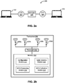
- FIG. 1 an environment 100 (that is exemplary) in which various embodiments may be employed is illustrated in FIG. 1 .
- Environment 100 includes a water body 102 and a land 104.
- Water body 102 for example, may be a sea or an ocean and land 104, for example, may include coastal areas or islands.
- a plurality of watercrafts for example, a ship 106, a ship 108, and a ship 110, while navigating in water body 102, may be in communication with one or more Base Transceiver Stations (BTSs), for example, a BTS 112, a BTS 114, and a BTS 116 on land 104.
- BTSs Base Transceiver Stations
- a watercraft for example, may include, but is not limited to a boat, a submarine, a hovercraft, and a seaplane.
- Each of the plurality of watercrafts may include a Customer Premises Equipment (CPE) or a mobile station that establishes communication with one or more BTSs.
- CPE Customer Premises Equipment
- the CPE installed on the watercraft establishes communication with a BTS.
- a CPE in ship 106 establishes communication with BTS 112
- a CPE in ship 108 establishes communication with BTS 114
- a CPE in ship 110 establishes communication with BTS 116.
- the communication may be established using a long range land-to-sea wireless communication link using Variable-Time-Slot-TDMA (VTS-TDMA) in the 5GHz unlicensed shared spectrum.
- VTS-TDMA Variable-Time-Slot-TDMA
- System 200 may be implemented in a land-to-sea wireless network by using a long range land-to-sea wireless communication link. It will be apparent to a person skilled in the art that system 200 is not limited to the land-to-sea wireless network.
- System 200 includes CPE 202 and BTS 204, such that, BTS 204 may be the serving BTS for CPE 202.
- system 200 includes a client computing device 222 that is communicatively coupled to CPE 202 and a server computing device 224 that is communicatively coupled to BTS 204.
- Client computing device 222 and server computing device 224 may be plugged into high speed Ethernet ports of CPE 202 and BTS 204 respectively and may be in the same L2 network.
- a communication session may be initiated between CPE 202 and BTS 204 through client computing device 222 and server computing device 224.
- the communication session may be an IPERF (or IxChariot) session that is initiated for downlink Transmission Control Protocol (TCP) throughput tests.
- link adaptation may be disabled (through a configuration knob) on both CPE 202 and BTS 204, while the communication session is initiated.
- the communication session may be routed through an attenuator 226, which may be a JFW variable software controlled attenuator. Attenuator 226 may be used to vary the attenuation levels while the communication session is ongoing. The method of calibration is further explained in detail in conjunction with FIG. 3 .
- Each of CPE 202 and BTS 204 may include transceiver 206, that enables communication between CPE 202 and BTS 204.
- Transceiver 206 includes an antenna array that may be used to establish communication with one or more of CPE 202 and BTS 204.
- the antenna array may include an antenna 208a, an antenna 208b, an antenna 208c, and an antenna 208d. It will be apparent to a person skilled in the art that the number of antennas in the antenna array are not limited to four.
- Transceiver 206 further includes a processor 210 that is communicatively coupled to antennas 208a to 208d. Processor 210 enables transceiver 206 to perform link adaptation by adapting transmission rate on the communication link between CPE 202 and BTS 204.
- Processor 210 is further communicatively coupled to a memory 212, which may be a non-volatile memory or a volatile memory.
- a memory 212 may be a non-volatile memory or a volatile memory.
- non-volatile memory may include, but are not limited to a flash memory, a Read Only Memory (ROM), a Programmable ROM (PROM), Erasable PROM (EPROM), and Electrically EPROM (EEPROM) memory.
- Examples of volatile memory may include, but are not limited Dynamic Random Access Memory (DRAM), and Static Random-Access memory (SRAM).
- Memory 212 may store processor instructions, which on execution may cause processor 210 to perform various steps than enable link adaptation by adapting transmission rate.
- memory 212 includes a configuration module 214, a table generation module 216, a Modulation and Coding Scheme (MCS) collection module 218, and an MCS processing module 220.
- Configuration module 214 is a functional unit that reads a plurality of configuration parameters stores in a non-volatile memory and loads it into the main memory (i.e., RAM). During power up BTS 204 and CPE 202, configuration module 214 may read the plurality of configuration parameters from the non-volatile memory and initialize the main memory.
- the plurality of configuration parameters may include, but are not limited to length of a probe packet (la_probe_pkt_len), number of probe packets to be transmitted at one time (la_num_probes), percentage of airframes that include probe packets (la_probe_fraction), period at which a receiver collects probe statistics (la_probe_stats_intvl), and threshold above which probe statistics are considered valid (la_confidence_level). This is further explained in detail in conjunction with FIG. 4 .
- Table generation module 216 generates a plurality of static tables in a test bed environment, which is explained in detail in conjunction with FIG. 3 .
- the plurality of static tables are disclosed in detail in FIG. 3 as tables 1 to 6.
- a plurality of probe packets may be sent, via the antenna array, to a receiver at each of a set of probe MCSs associated with a current MCS, based on a static MCS probe table disclosed in FIG. 3 . Thereafter, a receiver sends back a link adaption statistic packet, which is analyzed by MCS collection module 218.
- the link adaptation statistic packet may include information related to the number of probe packets that were successfully received by the receiver for each of the set of probe MCSs.
- MCS collection module 218 determines a percentage of probe packets successfully received by the receiver for each of the set of probe MCSs associated with the current MCS. Additionally, MCS collection module 218 determines Automatic Repeat Request (ARQ) retransmit percentage for the ongoing communication session on the current MCS. This is explained in detail in conjunction with FIG. 4 .
- ARQ Automatic Repeat Request
- MCS processing module 220 Based on the percentage of probe packets successfully received for each of the set of probe MCSs and based on one or more of the plurality of static tables, MCS processing module 220 identifies an MCS that is to be used for subsequent transmissions. In an embodiment, MCS processing module 220 may ramp-up from the current MCS. This is explained in detail in conjunction with FIG. 3 to FIG. 7 . In another embodiment, MCS processing module 220 may ramp-down or slap-down from the current MCS. This is explained in detail in conjunction with FIG. 8 . It will be apparent to a person skilled in the art that both embodiments discussed above (i.e., ramp-up and ramp-down) may be executed simultaneously.
- System 200 ensures that Quality of Service (QoS) (by way of throughput) is maximized for an end-user, while minimizing the use of satellite network and maximizing the use of long range land-to-sea wireless network including 4G and 5G but not limited to broadband, WiMAX, and Wi-Fi.
- QoS Quality of Service
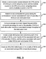
- FIG. 3 a flowchart of a method of calibrating transmission rate between a CPE and a BTS is illustrated, in accordance with an embodiment.
- This method may be implemented in a land-to-sea wireless network by using a long range land-to-sea wireless communication link. It will be apparent to a person skilled in the art that the method is not limited to the land-to-sea wireless network.
- a client computing device is communicatively coupled to the CPE and a server computing device is communicatively coupled to the BTS.
- the client computing device and the server computing device may be plugged into high speed Ethernet ports of the CPE and BTS respectively and may be in the same L2 network.
- a communication session is initiated between the CPE and the BTS through the client computing device and the server computing device.
- the communication session may be an IPERF (or IxChariot) session that is initiated for downlink Transmission Control Protocol (TCP) throughput tests.
- link adaptation may be disabled (through a configuration knob) on both the CPE and BTS, while the communication session is initiated.
- the communication session may be routed through an attenuator.
- the attenuator may be a JFW variable software controlled attenuator.
- a throughput associated with each of a plurality of Modulation and Coding Schemes may be determined.
- MCS Modulation and Coding Schemes
- the best achievable throughput is determined at a zero attenuation level for each of the plurality of MCSs, during the communication session. This is discussed in detail below.
- MCS may be set to 0 on the CPE (i.e., for the uplink) and on the BTS (i.e., for the downlink), MCS is set to X.
- the value of X may be represented by equation 1, for a dual frequency BTS configuration (i.e., four spatial streams) and equation 2, for a single frequency BTS configuration (i.e., two spatial streams): X ⁇ 0,30 X ⁇ 0,15
- the MCSs from 0 to 7 are associated with SS1
- the MCSs from 8 to 15 are associated with SS2
- the MCSs from 16 to 23 are associated with SS3
- the MCSs from 24 to 31 are associated with the SS4.
- downlink TCP throughput test may be run for about three minutes. Multiple such TCP throughput tests (for example, five in number) are run. These TCP throughput tests are then used to compute the average TCP throughput at a given MCS.
- an average Automatic Repeat Request (ARQ) retransmit percentage is computed for each of the plurality of MCSs at each attenuation level for an associated average throughput.
- ARQ Automatic Repeat Request
- the attenuation level may start at 0 dB and may be increased by 1dB till the attenuation level reaches 60 dB, for example.
- an average ARQ retransmit percentage is computed for the average throughout at that attenuation level. This is repeated for each of the plurality of MCS. In other words, for each MCS, at each attenuation level, ARQ retransmit percentage and throughput are measured. This is further explained in detail at step 310.
- a static MCS probe table which includes the plurality of MCSs and a set of probe MCSs associated with each of the plurality of MCSs, is created.
- a given MCS is mapped to a set of probe MCSs in the static MCS probe table.
- the static MCS probe table additionally includes throughput associated with each probe MCS in each set of probe MCSs.
- the static MCS probe table is used to adapt transmission rate between the CPE and the BTS in an actual or live scenario, when they are communicating directly with each other.
- the transmission rate may be adapted by modifying a current MCS to an MCS selected from an associated set of probe MCSs mapped to the current MCS in the static MCS probe table.
- a plurality of probe packets are sent at each of a set of probe MCSs associated with a current MCS to the receiver.
- the set of probe MCSs is selected from the plurality of MCSs based on predefined selection criteria.
- the predefined selections criteria may be that the set of probe MCSs includes MCSs that have similar throughput on different streams, in addition to a lower and higher MCS on the same stream. This is further explained in detail in conjunction with FIG. 3 .
- probe packets may be sent on five different probe MCSs for the current MCS.
- a static MCS probe table for single frequency configuration of the BTS is depicted in table 3 and a static MCS probe table for a dual frequency configuration of the BTS is depicted in table 4.
- Table 3 and table 4 are derived from table 2.
- an ARQ MCS table is created based on the plurality of MCSs and an associated average ARQ retransmit percentage determined at step 306.
- the ARQ MCS table includes an associated ARQ retransmit percentage threshold and an associated future MCS.
- a current MCS is changed to the associated future MCS, when ARQ retransmit percentage threshold linked with the current MCS is reached or exceeded. In other words, beyond a certain ARQ percentage, it is better to switch to an MCS that can provide similar or higher throughput under the given channel condition.
- the throughput for the MCS is determined at different attenuation levels, starting from 0 dB and moving to 60 dB, for example, at increments of 1 dB at each step. At a certain attenuation level, the throughput for the MCS falls sharply, at this point another MCS may provide the same or higher throughput at that attenuation level. This is illustrated by way of an example in the graph depicted below:
- throughput for the MCS 29 (which may be at 64 QAM) is determined at different attenuation levels.
- the throughput for the MCS 29 drops sharply and the MCS 28 (which may be 16 QAM) has same throughput at 17dB attenuation level, which remains more or less the same for few subsequent attenuation levels.
- the attenuation level of 17 dB is the switching point at which the ARQ retransmit percentage is recorded. This would be the ARQ retransmit percentage threshold for MCS 29, and MCS 28 would be the MCS to be switched to when this threshold is reached or exceeded.
- ARQ retransmit percentage threshold is computed for different MCSs. It will be apparent to a person skilled in the art that ARQ retransmit percentage threshold for each MCS may be determined at different attenuation levels.
- an ARQ MCS table for a single frequency BTS configuration is depicted by a table 5 given below and an ARQ MCS table for a dual frequency BTS configuration is depicted in table 6 given below.
- the ARQ MCS table may also be termed as a link adaptation slap down table.
- MCS 0 and MCS 8 are excluded from the slap down logic for single frequency configuration of the BTS.
- MCS 0, MCS 8, and MCS 31 are excluded from the slap down logic for dual frequency configuration of the BTS.
- the method ensures that QoS (by way of throughput) is maximized for an end-user, while minimizing the use of satellite network and maximizing the use of long range land-to-sea wireless network including 4G and 5G but not limited to broadband, WiMAX, and Wi-Fi.
- each of the CPE and the BTS may be configured with a plurality of configuration parameters.
- the BTS and CPE may read the plurality of configuration parameters from flash and initialize the variable in main memory.
- the plurality of configuration parameters may include, but are not limited to length of a probe packet (la_probe_pkt_len), number of probe packets to be transmitted at one time (la_num_probes), percentage of airframes that include probe packets (la_probe_fraction), period at which a receiver collects probe statistics (la_probe_stats_intvl), and threshold above which probe statistics are considered valid (la_confidence_level).
- the BTS and CPE may reset the MCS to 0, when a new connection is established and initialize the probe packet with random data during power up. Once the connection is established, the state is changed from unconnected to connected. Thereafter, link adapt will start based on the state change.
- a plurality of probe packets are sent at each of a set of probe MCSs associated with a current MCS, based on the static MCS probe table.
- the current MCS is 0, multiple probe packets are sent at following probe MCSs: 0, 1, 8, 2, and 3, as the current MCS of 0 is mapped to these probe MCSs in the table 3.
- the plurality of probe packets may be Media Access Control (MAC) Protocol Data Units (PDUs) that are included in MAC data packets and are transmitted as a 'burst' of data. Multiple MAC PDUs can go out in a single burst, in a (type, length, value) TLV packet, such that, all MAC PDUs are concatenated into a single airframe. Probe packets may be sent as a single airframe packet and may be sent multiple times within a single airframe. There are no retransmissions on probes.
- MAC Media Access Control
- PDUs Protocol Data Units
- a sender for example the CPE may sends out a series of probe packets to a receiver (for example, the BTS) based on the table 3 and 4, indexed by the current MCS, and statically determined. Additionally, to determine when to send probe packets, a random number generator module may be used. If the random number generator module returns a number less than the value of the configuration parameter: la_probe_fraction, then a probe packet may be transmitted. This may be evaluated within every 5 millisecond airframe.
- the length of the probe packet, i.e., la_probe_pkt_len, and the number of probe packets sent at a time, i.e., la_num_probes are configurable.
- the sender for example, the CPE
- the sender sends the next one in the probe list.
- the sender will continue to cycle through the probe list, until the sender receives a link adaptation statistics packet (which will be a MAC PDU packet) from the receiver (for example, the BTS).
- the link adaptation statistic packet may be received by the sender from the receiver after expiry of a predefined time period (for example, la_probe_stats_intvl).
- the receiver for example, the BTS
- the receiver may keep a record of the number of probe packets received from the sender (for example, the CPE) at a given MCS for the predefined time period, i.e., la_probe_stats_intvl.
- the receiver schedules the link adaptation statistic packet to be sent to the sender.
- the link adaptation statistic packet may include information related to the number of probe packets that were successfully received by the receiver for each of the set of probe MCSs.
- the receiver keeps a record of the number of packets received at each of the probe MCSs, i.e., 0, 1, 8, 2, and 3.
- a percentage of probe packets successfully received by a receiver for each of the set of probe MCSs associated with the current MCS is determined at step 408, based on the information in the link adaptation statistic packet.
- the current MCS may be 20 and thus, based on the table 4, 10 probe packets are sent on each of the following probe MCSs: 14, 20, 28, 21, and 22.
- the number of probe packets successfully received at the receiver at each probe MCS may be as follows: 8 probe packets at MCS 14, 8 probe packets at MCS 20, 6 probe packets at MCS 28, 8 probe packets at MCS 21, and 4 probe packets at MCS 22.
- These statistics are stored in the link adaptation statistic packet. Using these statistics, the sender may determine the percentage of probe packets successfully received by the receiver as: 80% for MCS 14, 80% for MCS 20, 60% for MCS 28, 80% for MCS 21, and 40% for MCS 22.
- an MCS is identified from the set of probe MCSs for subsequent transmissions at step 410. This is further explained in detail in conjunction with FIG. 5 , FIG. 6 , and FIG. 7 .
- This method is thus a ramp-up model, such that, MCS with a better throughput is selected for subsequent transmissions.
- the ARQ retransmit percentage may be used to determine if the current MCS needs to be modified. This may be determined based on information in the tables 5 and 6. When the ARQ retransmit percentage reaches or exceeds an associated threshold, the sender ramps down to a lower MCS. This is further explained in detail in conjunction with FIG. 8 .
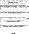
- a flowchart of a method for identifying a MCS for subsequent transmissions is illustrated, in accordance with an embodiment.
- the static MCS probe table for example, the tables 3 and 4
- a plurality of probe packets are sent at each of a set of probe MCSs associated with a current MCS.
- one or more MCSs are identified from the set of probe MCSs, such that, percentage of probe packets successfully received for the one or more MCS is greater than a confidence level percentage.
- the current MCS may be 20 and thus, based on the table 4, 10 probe packets are sent on each of the following probe MCSs: 14, 20, 28, 21, and 22.
- the number of probe packets successfully received at the receiver at each probe MCS may be as follows: 8 probe packets at MCS 14, 8 probe packets at MCS 20, 6 probe packets at MCS 28, 8 probe packets at MCS 21, and 4 probe packets at MCS 22.
- These statistics are stored in the link adaptation statistic packet.
- the sender may determine the percentage of probe packets successfully received by the receiver as: 80% for MCS 14, 80% for MCS 20, 60% for MCS 28, 80% for MCS 21, and 40% for MCS 22.
- the confidence level percentage may be fixed at 70%.
- MCS 14, MCS 20, and MCS 21 are identified out of the five probe MCSs.
- a throughput for each of the one or more MCS identified at step 502 is calculated based on an associated percentage of probe packets successfully received by the receiver.
- a throughput is calculated for each of: MCS 14, MCS 20, and MCS 21.
- MCS 28 and MCS 22 are ignored as they did not satisfy the criterion of exceeding the confidence level percentage. This is further explained in detail in conjunction with FIG. 6 .
- one of the one or more MCSs that has a highest throughput from amongst the one or more MCSs is selected for subsequent transmissions.
- a flowchart of a method of calculating throughput for one or more MCSs is illustrated, in accordance with an embodiment.
- the static MCS throughput table includes static throughputs for each of the plurality of MCSs computed in a testbed environment. This has been explained in detail in conjunction with FIG. 3 .
- static throughput is determined for each of MCS 14, MCS 20, and MCS 21 based on static throughput values given in table 2.
- MCS 14 has a static throughput of 59.1
- MCS 20 has a static throughput of 61.5
- MCS 21 has a static throughput of 71.2.
- a static throughput associated with each of the one or more MCSs is multiplied with an associated percentage of probe packets successfully received. This results in calculation of throughout for each of the one or more MCSs.
- static throughput for each of MCS 14, MCS 20, and MCS 21 is multiplied with the associated percentage, which is same for each of these MCSs, i.e., 80%.
- a flowchart of a method for identifying a MCS for subsequent transmissions is illustrated, in accordance with another embodiment.
- the static MCS probe table for example, the tables 3 and 4
- a plurality of probe packets are sent at each of a set of probe MCSs associated with a current MCS.
- a throughput for each MCS in the set of probe MCSs is calculated based on an associated percentage of probe packets successfully received by the receiver. This has been explained in detail in conjunction with FIG. 5 .
- a throughput for MCS 14 is calculated as 47.28, for MCS 20 as 49.2, for MCS 21 as 56.96.
- an average throughput is computed for the set of probe MCSs based on throughput calculated for each MCS in the set of probe MCSs.
- an MCS from a static MCS throughput table is identified.
- the average throughput is mapped to the closest throughput in the static MCS throughput table, such that, the average throughput is less than or equal to the mapped value.
- the MCS corresponding to this mapped throughput is then picked as the MCS for subsequent transmissions.
- the average throughput of 45.14 is compared with static throughputs given in table 2. Based on the comparison, the throughput of 44.8 is identified as being closest to the average throughput of 45.14. Thus, MCS 19 is identified as the MCS for subsequent transmissions. It will be apparent to a person skilled in the art that unlike the embodiment discussed in FIG. 5 and FIG. 6 , the embodiment discussed in FIG. 7 does not take into consideration the confidence level percentage.
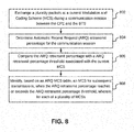
- a flowchart of a method of adapting transmission rate between a CPE and a BTS is illustrated, in accordance with another embodiment.
- a plurality packets are exchanged at a current MCS during an ongoing communication session between the CPE and the BTS.
- an ARQ retransmit percentage is determined for the communication session. The ARQ retransmit percentage may be determined based on an analysis of the link adaptation statistic packet.
- the ARQ retransmit percentage is compared with an ARQ retransmit percentage threshold associated with the current MCS.
- ARQ retransmit percentage thresholds associated with various MCSs may be stored in an ARQ MCS table, for example, the tables 5 and 6 given in FIG. 3 .
- the ARQ MCS table For each of a plurality of MCSs, the ARQ MCS table includes an associated ARQ retransmit percentage threshold and an associated subsequent MCS.
- an ARQ retransmit percentage threshold is 4.33 and a subsequent MCS or slap-down MCS is MCS 6.
- an ARQ retransmit percentage threshold is 1.92 and a subsequent MCS or slap-down MCS is MCS 8.
- an MCS for subsequent transmissions is identified at step 808, based on the ARQ MCS table.
- the current MCS may be MCS 7.
- the ARQ retransmit percentage for the ongoing communication session at MCS 7 may reach or exceed the ARQ retransmit percentage threshold of 4.33 (mapped to the MCS 7 in the table 5).
- MCS is immediately slapped down to MCS 6, based on the table 5. In other words, MCS 6 is used for subsequent transmissions.
- the current MCS may be MCS 16.
- the ARQ retransmit percentage for the ongoing communication session at MCS 16 may reach or exceed the ARQ retransmit percentage threshold of 1.92 (mapped to the MCS 16 in the table 6).
- the ARQ retransmit percentage threshold of 1.92 is reached or exceeded, MCS is immediately slapped down to MCS 8, based on the table 6. In other words, MCS 8 is used for subsequent transmissions.
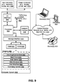
- FIG. 9 is a block diagram of an exemplary computer system for implementing various embodiments.
- Computer system 902 may include a central processing unit (“CPU” or "processor") 904.
- Processor 904 may include at least one data processor for executing program components for executing user- or system-generated requests.
- a user may include a person, a person using a device such as such as those included in this disclosure, or such a device itself.
- Processor 904 may include specialized processing units such as integrated system (bus) controllers, memory management control units, floating point units, graphics processing units, digital signal processing units, etc.
- bus integrated system
- Processor 904 may include a microprocessor, such as AMD® ATHLON® microprocessor, DURON® microprocessor OR OPTERON® microprocessor, ARM's application, embedded or secure processors, IBM® POWERPC®, INTEL'S CORE® processor, ITANIUM® processor, XEON® processor, CELERON® processor or other line of processors, etc.
- Processor 904 may be implemented using mainframe, distributed processor, multi-core, parallel, grid, or other architectures. Some embodiments may utilize embedded technologies like application-specific integrated circuits (ASICs), digital signal processors (DSPs), Field Programmable Gate Arrays (FPGAs), etc.
- ASICs application-specific integrated circuits
- DSPs digital signal processors
- FPGAs Field Programmable Gate Arrays
- I/O interface 906 may employ communication protocols/methods such as, without limitation, audio, analog, digital, monoaural, RCA, stereo, IEEE-1394, serial bus, universal serial bus (USB), infrared, PS/2, BNC, coaxial, component, composite, digital visual interface (DVI), high-definition multimedia interface (HDMI), RF antennas, S-Video, VGA, IEEE 802.n /b/g/n/x, Bluetooth, cellular (e.g., code-division multiple access (CDMA), high-speed packet access (HSPA+), global system for mobile communications (GSM), long-term evolution (LTE), WiMax, or the like), etc.
- CDMA code-division multiple access
- HSPA+ high-speed packet access
- GSM global system for mobile communications
- LTE long-term evolution
- WiMax wireless wide area network
- I/O interface 906 computer system 902 may communicate with one or more I/O devices.
- an input device 908 may be an antenna, keyboard, mouse, joystick, (infrared) remote control, camera, card reader, fax machine, dongle, biometric reader, microphone, touch screen, touchpad, trackball, sensor (e.g., accelerometer, light sensor, GPS, gyroscope, proximity sensor, or the like), stylus, scanner, storage device, transceiver, video device/source, visors, etc.
- An output device 910 may be a printer, fax machine, video display (e.g., cathode ray tube (CRT), liquid crystal display (LCD), light-emitting diode (LED), plasma, or the like), audio speaker, etc.
- a transceiver 912 may be disposed in connection with processor 904. Transceiver 912 may facilitate various types of wireless transmission or reception.
- transceiver 912 may include an antenna operatively connected to a transceiver chip (e.g., TEXAS® INSTRUMENTS WILINK WL1283® transceiver, BROADCOM® BCM4550IUB8® transceiver, INFINEON TECHNOLOGIES® X-GOLD 618-PMB9800® transceiver, or the like), providing IEEE 802.11a/b/g/n, Bluetooth, FM, global positioning system (GPS), 2G/3G HSDPA/HSUPA communications, etc.
- a transceiver chip e.g., TEXAS® INSTRUMENTS WILINK WL1283® transceiver, BROADCOM® BCM4550IUB8® transceiver, INFINEON TECHNOLOGIES® X-GOLD 618-PMB9800® transceiver, or the like
- IEEE 802.11a/b/g/n Bluetooth
- FM FM
- GPS global positioning system
- processor 904 may be disposed in communication with a communication network 914 via a network interface 916.
- Network interface 916 may communicate with communication network 914.
- Network interface 916 may employ connection protocols including, without limitation, direct connect, Ethernet (e.g., twisted pair 50/500/5000 Base T), transmission control protocol/internet protocol (TCP/IP), token ring, IEEE 802.11a/b/g/n/x, etc.
- Communication network 914 may include, without limitation, a direct interconnection, local area network (LAN), wide area network (WAN), wireless network (e.g., using Wireless Application Protocol), the Internet, etc.
- LAN local area network
- WAN wide area network
- wireless network e.g., using Wireless Application Protocol
- These devices may include, without limitation, personal computer(s), server(s), fax machines, printers, scanners, various mobile devices such as cellular telephones, smartphones (e.g., APPLE® IPHONE® smartphone, BLACKBERRY® smartphone, ANDROID® based phones, etc.), tablet computers, eBook readers (AMAZON® KINDLE® ereader, NOOK® tablet computer, etc.), laptop computers, notebooks, gaming consoles (MICROSOFT® XBOX® gaming console, NINTENDO® DS® gaming console, SONY® PLAYSTATION® gaming console, etc.), or the like.
- computer system 902 may itself embody one or more of these devices.
- processor 904 may be disposed in communication with one or more memory devices (e.g., RAM 926, ROM 928, etc.) via a storage interface 924.
- Storage interface 924 may connect to memory 930 including, without limitation, memory drives, removable disc drives, etc., employing connection protocols such as serial advanced technology attachment (SATA), integrated drive electronics (IDE), IEEE-1394, universal serial bus (USB), fiber channel, small computer systems interface (SCSI), etc.
- the memory drives may further include a drum, magnetic disc drive, magneto-optical drive, optical drive, redundant array of independent discs (RAID), solid-state memory devices, solid-state drives, etc.
- Memory 930 may store a collection of program or database components, including, without limitation, an operating system 932, user interface application 934, web browser 936, mail server 938, mail client 940, user/application data 942 (e.g., any data variables or data records discussed in this disclosure), etc.
- Operating system 932 may facilitate resource management and operation of computer system 902.
- Examples of operating systems 932 include, without limitation, APPLE® MACINTOSH® OS X platform, UNIX platform, Unix-like system distributions (e.g., Berkeley Software Distribution (BSD), FreeBSD, NetBSD, OpenBSD, etc.), LINUX distributions (e.g., RED HAT®, UBUNTU®, KUBUNTU®, etc.), IBM® OS/2 platform, MICROSOFT® WINDOWS® platform (XP, Vista/7/8, etc.), APPLE® IOS® platform, GOOGLE® ANDROID® platform, BLACKBERRY® OS platform, or the like.
- User interface 934 may facilitate display, execution, interaction, manipulation, or operation of program components through textual or graphical facilities.
- GUIs may provide computer interaction interface elements on a display system operatively connected to computer system 902, such as cursors, icons, check boxes, menus, scrollers, windows, widgets, etc.
- Graphical user interfaces may be employed, including, without limitation, APPLE® Macintosh® operating systems' AQUA® platform, IBM® OS/2® platform, MICROSOFT® WINDOWS® platform (e.g., AERO® platform, METRO® platform, etc.), UNIX X-WINDOWS, web interface libraries (e.g., ACTIVEX® platform, JAVA® programming language, JAVASCRIPT® programming language, AJAX® programming language, HTML, ADOBE® FLASH® platform, etc.), or the like.
- Web browser 936 may be a hypertext viewing application, such as MICROSOFT® INTERNET EXPLORER® web browser, GOOGLE® CHROME® web browser, MOZILLA® FIREFOX® web browser, APPLE® SAFARI® web browser, etc. Secure web browsing may be provided using HTTPS (secure hypertext transport protocol), secure sockets layer (SSL), Transport Layer Security (TLS), etc. Web browsers may utilize facilities such as AJAX, DHTML, ADOBE® FLASH® platform, JAVASCRIPT® programming language, JAVA® programming language, application programming interfaces (APis), etc.
- HTTPS secure hypertext transport protocol
- SSL secure sockets layer
- TLS Transport Layer Security
- Web browsers may utilize facilities such as AJAX, DHTML, ADOBE® FLASH® platform, JAVASCRIPT® programming language, JAVA® programming language, application programming interfaces (APis), etc.
- computer system 902 may implement a mail server 938 stored program component.
- Mail server 938 may be an Internet mail server such as MICROSOFT® EXCHANGE® mail server, or the like.
- Mail server 938 may utilize facilities such as ASP, ActiveX, ANSI C++/C#, MICROSOFT .NET® programming language, CGI scripts, JAVA® programming language, JAVASCRIPT® programming language, PERL® programming language, PHP® programming language, PYTHON® programming language, WebObjects, etc.
- Mail server 938 may utilize communication protocols such as internet message access protocol (IMAP), messaging application programming interface (MAPI), Microsoft Exchange, post office protocol (POP), simple mail transfer protocol (SMTP), or the like.
- IMAP internet message access protocol
- MAPI messaging application programming interface
- POP post office protocol
- SMTP simple mail transfer protocol
- computer system 902 may implement a mail client 940 stored program component.
- Mail client 940 may be a mail viewing application, such as APPLE MAIL® mail client, MICROSOFT ENTOURAGE® mail client, MICROSOFT OUTLOOK® mail client, MOZILLA THUNDERBIRD® mail client, etc.
- computer system 902 may store user/application data 942, such as the data, variables, records, etc. as described in this disclosure.
- databases may be implemented as fault-tolerant, relational, scalable, secure databases such as ORACLE® database OR SYBASE® database.
- databases may be implemented using standardized data structures, such as an array, hash, linked list, struct, structured text file (e.g., XML), table, or as object-oriented databases (e.g., using OBJECTSTORE® object database, POET® object database, ZOPE® object database, etc.).
- object databases e.g., using OBJECTSTORE® object database, POET® object database, ZOPE® object database, etc.
- Such databases may be consolidated or distributed, sometimes among the various computer systems discussed above in this disclosure. It is to be understood that the structure and operation of the any computer or database component may be combined, consolidated, or distributed in any working combination.
- Various embodiments of the invention provide method, device, and system for calibrating and adapting transmission rate in wireless communication.
- the provided method uses static table driven MCS ramp-up (which is slow) and MCS slap-down (which is aggressive) link adaptation procedure, which pushes throughput to the theoretical limits. This can be applied to any similar link adaptation requirement, for example, but not limited to 3G, 3.5G, 4G, WiMAX, and Wi-Fi.
- the provided methods is a statistical approach that is simpler to implement and execute.
- the method further ensures that QoS (throughput) is maximized for the end-user, while minimizing the use of satellite network and maximizing the use of LRLS network including 4G, 5G but not limited to broadband, WiMAX, Wi-Fi.
- a computer-readable storage medium refers to any type of physical memory on which information or data readable by a processor may be stored.
- a computer-readable storage medium may store instructions for execution by one or more processors, including instructions for causing the processor(s) to perform steps or stages consistent with the embodiments described herein.
- the term "computer-readable medium” should be understood to include tangible items and exclude carrier waves and transient signals, i.e., be non-transitory. Examples include random access memory (RAM), read-only memory (ROM), volatile memory, nonvolatile memory, hard drives, CD ROMs, DVDs, flash drives, disks, and any other known physical storage media.
Landscapes
- Engineering & Computer Science (AREA)
- Computer Networks & Wireless Communication (AREA)
- Signal Processing (AREA)
- Quality & Reliability (AREA)
- Physics & Mathematics (AREA)
- Probability & Statistics with Applications (AREA)
- Artificial Intelligence (AREA)
- Mobile Radio Communication Systems (AREA)
Claims (9)
- Verfahren zur Anpassung der Übertragungsrate zwischen einem Kundenstandortgerät (KSG) und einer Basistransceiverstation (BTS), wobei das Verfahren umfasst:ein Senden, basierend auf einer statischen MCS-(Modulation and Coding Schemes)-Sondentabelle, einer Vielzahl von Sondenpaketen an jedem eines Satzes von Sonden-MCS, die einem aktuellen MCS zugeordnet sind, wobei die statische MCS-Sondentabelle eine Vielzahl von MCS und einen Satz von Sonden-MCS umfasst, die jeder der Vielzahl von MCS zugeordnet sind;ein Bestimmen eines Prozentsatzes von Sondenpaketen, die von einem Empfänger erfolgreich empfangen wurden, für jedes des Satzes von Sonden-MCS, die dem aktuellen MCS zugeordnet sind, basierend auf einem Linkanpassungsstatistikpaket, das vom Empfänger empfangen wurde; undein Identifizieren eines MCS aus dem Satz von Sonden-MCS für nachfolgende Übertragungen basierend auf dem bestimmten Prozentsatz, dadurch gekennzeichnet, dass das Identifizieren des MCS für nachfolgende Übertragungen umfasst:ein Berechnen des Durchsatzes für jedes MCS im Satz von Sonden-MCS basierend auf einem zugeordneten Prozentsatz an Sondenpaketen, die vom Empfänger erfolgreich empfangen werden;ein Berechnen eines durchschnittlichen Durchsatzes für den Satz von Sonden-MCS, basierend auf dem für jeden des Satzes von Sonden-MCS berechneten Durchsatz; undein Identifizieren, basierend auf dem durchschnittlichen Durchsatz, eines MCS aus einer statischen MCS-Durchsatztabelle, umfassend statische Durchsätze für jedes der Vielzahl von MCS, die in einer Testbed-Umgebung berechnet werden.
- Verfahren nach Anspruch 1, ferner umfassend ein Empfangen des Linkanpassungsstatistikpakets vom Empfänger nach Ablauf eines vordefinierten Zeitraums, wobei das Linkanpassungsstatistikpaket Informationen umfasst, die sich auf die Anzahl von Sondenpaketen beziehen, die vom Empfänger für jedes des Satzes von Sonden-MCS erfolgreich empfangen werden.
- Verfahren nach Anspruch 1 oder 2, wobei das Berechnen des Durchsatzes für jedes der MCS im Satz von Sonden-MCS umfasst:ein Bestimmen eines statischen Durchsatzes, der jedem der MCS im Satz der Sonden-MCS zugeordnet ist, basierend auf einer statischen MCS-Durchsatztabelle, wobei die statische MCS-Durchsatztabelle statische Durchsätze für jedes der Vielzahl von MCS umfasst, die in einer Testbed-Umgebung berechnet werden; undein Multiplizieren eines statischen Durchsatzes, der jedem der MCS im Satz von Sonden-MCS zugeordnet ist, mit einem zugeordneten Prozentsatz von erfolgreich empfangenen Sondenpaketen.
- Verfahren nach einem der vorangehenden Ansprüche, ferner umfassend ein Konfigurieren jedes der KSG und BTS mit einer Vielzahl von Konfigurationsparametern.
- Transceiver zur Anpassung der Übertragungsrate zwischen einem Kundenstandortgerät (KSG) und einer Basistransceiverstation (BTS), wobei der Transceiver umfasst:ein Antennenarray;einen Prozessor, der kommunikativ mit dem Antennenarray gekoppelt ist; undeinen Speicher, der kommunikativ mit dem Prozessor gekoppelt ist, wobei der Speicher Prozessoranweisungen speichert, die bei Ausführung den Prozessor veranlassen, um:basierend auf einer statischen MCS-(Modulation and Coding Schemes)-Sondentabelle eine Vielzahl von Sondenpaketen an jedes eines Satzes von Sonden-MCS, die einem aktuellen MCS zugeordnet sind, zu senden, wobei die statische MCS-Sondentabelle eine Vielzahl von MCS und einen Satz von Sonden-MCS umfasst, die jeder der Vielzahl von MCS zugeordnet sind;einen Prozentsatz von Sondenpaketen, die von einem Empfänger erfolgreich empfangen wurden, für jedes des Satzes von Sonden-MCS zu bestimmen, die dem aktuellen MCS zugeordnet sind, basierend auf einem Linkanpassungsstatistikpaket, das vom Empfänger empfangen wurde; undein MCS aus dem Satz von Sonden-MCS für nachfolgende Übertragungen basierend auf dem bestimmten Prozentsatz zu identifizieren,dadurch gekennzeichnet, dass zum Identifizieren des MCS für nachfolgende Übertragungen die Prozessoranweisungen den Prozessor ferner veranlassen, um:den Durchsatz für jedes MCS im Satz von Sonden-MCS basierend auf einem zugeordneten Prozentsatz an Sondenpaketen zu berechnen, die vom Empfänger erfolgreich empfangen werden;einen durchschnittlichen Durchsatz für den Satz von Sonden-MCS, basierend auf dem für jeden des Satzes von Sonden-MCS berechneten Durchsatz zu berechnen; undbasierend auf dem durchschnittlichen Durchsatz ein MCS aus einer statischen MCS-Durchsatztabelle, umfassend statische Durchsätze für jedes der Vielzahl von MCS, zu identifizieren, die in einer Testbed-Umgebung berechnet werden.
- Transceiver nach Anspruch 5, wobei die Prozessoranweisungen den Prozessor ferner veranlassen, um das Linkanpassungsstatistikpaket vom Empfänger nach Ablauf eines vordefinierten Zeitraums zu empfangen, wobei das Linkanpassungsstatistikpaket Informationen umfasst, die sich auf die Anzahl von Sondenpaketen beziehen, die vom Empfänger für jeden des Satzes von Sonden-MCS erfolgreich empfangen werden.
- Transceiver nach Anspruch 5 oder 6, wobei zum Berechnen des Durchsatzes für jedes der MCS im Satz von Sonden-MCS die Prozessoranweisungen den Prozessor ferner veranlassen, um:einen statischen Durchsatz, der jedem der MCS im Satz der Sonden-MCS zugeordnet ist, basierend auf einer statischen MCS-Durchsatztabelle zu bestimmen, wobei die statische MCS-Durchsatztabelle statische Durchsätze für jedes der Vielzahl von MCS umfasst, die in einer Testbed-Umgebung berechnet werden; undeinen statischen Durchsatz, der jedem der MCS im Satz von Sonden-MCS zugeordnet ist, mit einem zugeordneten Prozentsatz von erfolgreich empfangenen Sondenpaketen zu multiplizieren.
- Transceiver nach einem der Ansprüche 5 bis 7, wobei die Prozessoranweisungen den Prozessor ferner veranlassen, jedes der KSG und der BTS mit einer Vielzahl von Konfigurationsparametern zu konfigurieren.
- Transceiver nach einem der Ansprüche 5 bis 8, wobei eines der KSG und der BTS den Transceiver umfasst.
Applications Claiming Priority (2)
| Application Number | Priority Date | Filing Date | Title |
|---|---|---|---|
| US15/899,047 US10355810B1 (en) | 2018-02-19 | 2018-02-19 | Method, device, and system for calibrating and adapting transmission rate in wireless communication |
| IN201844009847 | 2018-03-17 |
Publications (2)
| Publication Number | Publication Date |
|---|---|
| EP3528408A1 EP3528408A1 (de) | 2019-08-21 |
| EP3528408B1 true EP3528408B1 (de) | 2020-10-14 |
Family
ID=67251146
Family Applications (1)
| Application Number | Title | Priority Date | Filing Date |
|---|---|---|---|
| EP18164813.0A Not-in-force EP3528408B1 (de) | 2018-02-19 | 2018-03-28 | Verfahren, vorrichtung und system zur kalibrierung und anpassung der übertragungsrate in drahtloser kommunikation |
Country Status (1)
| Country | Link |
|---|---|
| EP (1) | EP3528408B1 (de) |
Families Citing this family (2)
| Publication number | Priority date | Publication date | Assignee | Title |
|---|---|---|---|---|
| US11757564B2 (en) | 2019-12-02 | 2023-09-12 | Qualcomm Incorporated | Link adaptation using transmission rate options |
| EP4539366A1 (de) * | 2023-10-13 | 2025-04-16 | Fraunhofer-Gesellschaft zur Förderung der angewandten Forschung e.V. | Senden von testsequenzen zur auswahl von sendeeigenschaften bei einem funk-transceiver, funknetzwerk und verfahren zum betreiben von funk-transceivern |
Family Cites Families (2)
| Publication number | Priority date | Publication date | Assignee | Title |
|---|---|---|---|---|
| US8040843B2 (en) * | 2007-01-21 | 2011-10-18 | Broadcom Corporation | Transmit scheme adaptation for wireless data transmissions |
| US8184551B2 (en) * | 2008-08-08 | 2012-05-22 | Broadcom Corporation | Throughput-based rate adaptation for wireless transmissions |
-
2018
- 2018-03-28 EP EP18164813.0A patent/EP3528408B1/de not_active Not-in-force
Non-Patent Citations (1)
| Title |
|---|
| None * |
Also Published As
| Publication number | Publication date |
|---|---|
| EP3528408A1 (de) | 2019-08-21 |
Similar Documents
| Publication | Publication Date | Title |
|---|---|---|
| US10355810B1 (en) | Method, device, and system for calibrating and adapting transmission rate in wireless communication | |
| US10374882B2 (en) | Systems and methods for identifying causes of quality degradation in wireless networks | |
| US20200195539A1 (en) | Latency prediction and guidance in wireless communication systems | |
| US8611228B2 (en) | Anomaly detection method and system and maintenance method and system | |
| EP3557793B1 (de) | Verfahren und vorrichtung zur einstellung der verbindungsanpassung einer aussenschleife | |
| US9788325B2 (en) | Methods and systems for radio carriers management in a wireless broadband network | |
| US11606181B2 (en) | Data transmission method and apparatus | |
| CN109587761B (zh) | 在异构无线通信网络中进行数据路径切换的方法和系统 | |
| US20230038430A1 (en) | Network-based adaptive streaming media parameter adjustment method and an apparatus | |
| CN101682401A (zh) | 基于纠错值的信道控制 | |
| JP6811333B2 (ja) | Urllcのための拡張されたチャネル品質指標(cqi)測定手順 | |
| CN104754633B (zh) | 一种互干扰测试方法及装置 | |
| US12160303B2 (en) | Systems and methods for providing messaging for unmanned aerial vehicles | |
| EP3528408B1 (de) | Verfahren, vorrichtung und system zur kalibrierung und anpassung der übertragungsrate in drahtloser kommunikation | |
| US9609660B2 (en) | System and method for adaptive downlink scheduler for wireless networks | |
| US20190393981A1 (en) | Method and apparatus for handover aware cqi adjustment in wireless networks | |
| EP3528545B1 (de) | Verfahren, system und vorrichtung zur verwaltung von netzwerkeingabe und bts-übergabe in drahtlosen land-see-netzwerken | |
| CN110278053B (zh) | 无线通信中的传输速率校准与自适应的方法、装置和系统 | |
| CN106105360A (zh) | 调制编码方式的选择方法及基站 | |
| EP3361771B1 (de) | Verfahren und systeme für nachbarschaftsbeziehungsmanagement in einem drahtlosbreitbandnetzwerk | |
| CN115174031A (zh) | 一种调度方法、装置、设备及可读存储介质 | |
| US11316648B2 (en) | Method and system for data packet transmission in downlink | |
| EP3035759B1 (de) | System und verfahren zur adaptiven downlink-zeitplanung für drahtlose netzwerke | |
| US11121804B2 (en) | Base station, radio terminal, radio communication system, radio communication control method, and program | |
| JP6952653B2 (ja) | 端末装置の送信電力を制御する基地局装置、その制御方法、及びプログラム |
Legal Events
| Date | Code | Title | Description |
|---|---|---|---|
| PUAI | Public reference made under article 153(3) epc to a published international application that has entered the european phase |
Free format text: ORIGINAL CODE: 0009012 |
|
| STAA | Information on the status of an ep patent application or granted ep patent |
Free format text: STATUS: THE APPLICATION HAS BEEN PUBLISHED |
|
| AK | Designated contracting states |
Kind code of ref document: A1 Designated state(s): AL AT BE BG CH CY CZ DE DK EE ES FI FR GB GR HR HU IE IS IT LI LT LU LV MC MK MT NL NO PL PT RO RS SE SI SK SM TR |
|
| AX | Request for extension of the european patent |
Extension state: BA ME |
|
| STAA | Information on the status of an ep patent application or granted ep patent |
Free format text: STATUS: REQUEST FOR EXAMINATION WAS MADE |
|
| 17P | Request for examination filed |
Effective date: 20200219 |
|
| RBV | Designated contracting states (corrected) |
Designated state(s): AL AT BE BG CH CY CZ DE DK EE ES FI FR GB GR HR HU IE IS IT LI LT LU LV MC MK MT NL NO PL PT RO RS SE SI SK SM TR |
|
| GRAP | Despatch of communication of intention to grant a patent |
Free format text: ORIGINAL CODE: EPIDOSNIGR1 |
|
| STAA | Information on the status of an ep patent application or granted ep patent |
Free format text: STATUS: GRANT OF PATENT IS INTENDED |
|
| RIC1 | Information provided on ipc code assigned before grant |
Ipc: H04L 1/00 20060101AFI20200417BHEP Ipc: H04L 1/18 20060101ALI20200417BHEP |
|
| INTG | Intention to grant announced |
Effective date: 20200513 |
|
| GRAS | Grant fee paid |
Free format text: ORIGINAL CODE: EPIDOSNIGR3 |
|
| GRAA | (expected) grant |
Free format text: ORIGINAL CODE: 0009210 |
|
| STAA | Information on the status of an ep patent application or granted ep patent |
Free format text: STATUS: THE PATENT HAS BEEN GRANTED |
|
| AK | Designated contracting states |
Kind code of ref document: B1 Designated state(s): AL AT BE BG CH CY CZ DE DK EE ES FI FR GB GR HR HU IE IS IT LI LT LU LV MC MK MT NL NO PL PT RO RS SE SI SK SM TR |
|
| REG | Reference to a national code |
Ref country code: GB Ref legal event code: FG4D |
|
| REG | Reference to a national code |
Ref country code: AT Ref legal event code: REF Ref document number: 1324602 Country of ref document: AT Kind code of ref document: T Effective date: 20201015 Ref country code: CH Ref legal event code: EP |
|
| REG | Reference to a national code |
Ref country code: DE Ref legal event code: R096 Ref document number: 602018008613 Country of ref document: DE |
|
| REG | Reference to a national code |
Ref country code: IE Ref legal event code: FG4D |
|
| REG | Reference to a national code |
Ref country code: AT Ref legal event code: MK05 Ref document number: 1324602 Country of ref document: AT Kind code of ref document: T Effective date: 20201014 |
|
| REG | Reference to a national code |
Ref country code: NL Ref legal event code: MP Effective date: 20201014 |
|
| PG25 | Lapsed in a contracting state [announced via postgrant information from national office to epo] |
Ref country code: GR Free format text: LAPSE BECAUSE OF FAILURE TO SUBMIT A TRANSLATION OF THE DESCRIPTION OR TO PAY THE FEE WITHIN THE PRESCRIBED TIME-LIMIT Effective date: 20210115 Ref country code: NO Free format text: LAPSE BECAUSE OF FAILURE TO SUBMIT A TRANSLATION OF THE DESCRIPTION OR TO PAY THE FEE WITHIN THE PRESCRIBED TIME-LIMIT Effective date: 20210114 Ref country code: PT Free format text: LAPSE BECAUSE OF FAILURE TO SUBMIT A TRANSLATION OF THE DESCRIPTION OR TO PAY THE FEE WITHIN THE PRESCRIBED TIME-LIMIT Effective date: 20210215 Ref country code: RS Free format text: LAPSE BECAUSE OF FAILURE TO SUBMIT A TRANSLATION OF THE DESCRIPTION OR TO PAY THE FEE WITHIN THE PRESCRIBED TIME-LIMIT Effective date: 20201014 Ref country code: FI Free format text: LAPSE BECAUSE OF FAILURE TO SUBMIT A TRANSLATION OF THE DESCRIPTION OR TO PAY THE FEE WITHIN THE PRESCRIBED TIME-LIMIT Effective date: 20201014 |
|
| REG | Reference to a national code |
Ref country code: LT Ref legal event code: MG4D |
|
| PG25 | Lapsed in a contracting state [announced via postgrant information from national office to epo] |
Ref country code: AT Free format text: LAPSE BECAUSE OF FAILURE TO SUBMIT A TRANSLATION OF THE DESCRIPTION OR TO PAY THE FEE WITHIN THE PRESCRIBED TIME-LIMIT Effective date: 20201014 Ref country code: ES Free format text: LAPSE BECAUSE OF FAILURE TO SUBMIT A TRANSLATION OF THE DESCRIPTION OR TO PAY THE FEE WITHIN THE PRESCRIBED TIME-LIMIT Effective date: 20201014 Ref country code: BG Free format text: LAPSE BECAUSE OF FAILURE TO SUBMIT A TRANSLATION OF THE DESCRIPTION OR TO PAY THE FEE WITHIN THE PRESCRIBED TIME-LIMIT Effective date: 20210114 Ref country code: IS Free format text: LAPSE BECAUSE OF FAILURE TO SUBMIT A TRANSLATION OF THE DESCRIPTION OR TO PAY THE FEE WITHIN THE PRESCRIBED TIME-LIMIT Effective date: 20210214 Ref country code: LV Free format text: LAPSE BECAUSE OF FAILURE TO SUBMIT A TRANSLATION OF THE DESCRIPTION OR TO PAY THE FEE WITHIN THE PRESCRIBED TIME-LIMIT Effective date: 20201014 Ref country code: PL Free format text: LAPSE BECAUSE OF FAILURE TO SUBMIT A TRANSLATION OF THE DESCRIPTION OR TO PAY THE FEE WITHIN THE PRESCRIBED TIME-LIMIT Effective date: 20201014 Ref country code: SE Free format text: LAPSE BECAUSE OF FAILURE TO SUBMIT A TRANSLATION OF THE DESCRIPTION OR TO PAY THE FEE WITHIN THE PRESCRIBED TIME-LIMIT Effective date: 20201014 |
|
| PG25 | Lapsed in a contracting state [announced via postgrant information from national office to epo] |
Ref country code: HR Free format text: LAPSE BECAUSE OF FAILURE TO SUBMIT A TRANSLATION OF THE DESCRIPTION OR TO PAY THE FEE WITHIN THE PRESCRIBED TIME-LIMIT Effective date: 20201014 Ref country code: NL Free format text: LAPSE BECAUSE OF FAILURE TO SUBMIT A TRANSLATION OF THE DESCRIPTION OR TO PAY THE FEE WITHIN THE PRESCRIBED TIME-LIMIT Effective date: 20201014 |
|
| REG | Reference to a national code |
Ref country code: DE Ref legal event code: R097 Ref document number: 602018008613 Country of ref document: DE |
|
| PG25 | Lapsed in a contracting state [announced via postgrant information from national office to epo] |
Ref country code: LT Free format text: LAPSE BECAUSE OF FAILURE TO SUBMIT A TRANSLATION OF THE DESCRIPTION OR TO PAY THE FEE WITHIN THE PRESCRIBED TIME-LIMIT Effective date: 20201014 Ref country code: SK Free format text: LAPSE BECAUSE OF FAILURE TO SUBMIT A TRANSLATION OF THE DESCRIPTION OR TO PAY THE FEE WITHIN THE PRESCRIBED TIME-LIMIT Effective date: 20201014 Ref country code: RO Free format text: LAPSE BECAUSE OF FAILURE TO SUBMIT A TRANSLATION OF THE DESCRIPTION OR TO PAY THE FEE WITHIN THE PRESCRIBED TIME-LIMIT Effective date: 20201014 Ref country code: EE Free format text: LAPSE BECAUSE OF FAILURE TO SUBMIT A TRANSLATION OF THE DESCRIPTION OR TO PAY THE FEE WITHIN THE PRESCRIBED TIME-LIMIT Effective date: 20201014 Ref country code: CZ Free format text: LAPSE BECAUSE OF FAILURE TO SUBMIT A TRANSLATION OF THE DESCRIPTION OR TO PAY THE FEE WITHIN THE PRESCRIBED TIME-LIMIT Effective date: 20201014 Ref country code: SM Free format text: LAPSE BECAUSE OF FAILURE TO SUBMIT A TRANSLATION OF THE DESCRIPTION OR TO PAY THE FEE WITHIN THE PRESCRIBED TIME-LIMIT Effective date: 20201014 |
|
| PLBE | No opposition filed within time limit |
Free format text: ORIGINAL CODE: 0009261 |
|
| STAA | Information on the status of an ep patent application or granted ep patent |
Free format text: STATUS: NO OPPOSITION FILED WITHIN TIME LIMIT |
|
| PG25 | Lapsed in a contracting state [announced via postgrant information from national office to epo] |
Ref country code: DK Free format text: LAPSE BECAUSE OF FAILURE TO SUBMIT A TRANSLATION OF THE DESCRIPTION OR TO PAY THE FEE WITHIN THE PRESCRIBED TIME-LIMIT Effective date: 20201014 |
|
| 26N | No opposition filed |
Effective date: 20210715 |
|
| PG25 | Lapsed in a contracting state [announced via postgrant information from national office to epo] |
Ref country code: IT Free format text: LAPSE BECAUSE OF FAILURE TO SUBMIT A TRANSLATION OF THE DESCRIPTION OR TO PAY THE FEE WITHIN THE PRESCRIBED TIME-LIMIT Effective date: 20201014 Ref country code: MC Free format text: LAPSE BECAUSE OF FAILURE TO SUBMIT A TRANSLATION OF THE DESCRIPTION OR TO PAY THE FEE WITHIN THE PRESCRIBED TIME-LIMIT Effective date: 20201014 Ref country code: AL Free format text: LAPSE BECAUSE OF FAILURE TO SUBMIT A TRANSLATION OF THE DESCRIPTION OR TO PAY THE FEE WITHIN THE PRESCRIBED TIME-LIMIT Effective date: 20201014 |
|
| REG | Reference to a national code |
Ref country code: CH Ref legal event code: PL |
|
| PG25 | Lapsed in a contracting state [announced via postgrant information from national office to epo] |
Ref country code: SI Free format text: LAPSE BECAUSE OF FAILURE TO SUBMIT A TRANSLATION OF THE DESCRIPTION OR TO PAY THE FEE WITHIN THE PRESCRIBED TIME-LIMIT Effective date: 20201014 |
|
| REG | Reference to a national code |
Ref country code: BE Ref legal event code: MM Effective date: 20210331 |
|
| PG25 | Lapsed in a contracting state [announced via postgrant information from national office to epo] |
Ref country code: LI Free format text: LAPSE BECAUSE OF NON-PAYMENT OF DUE FEES Effective date: 20210331 Ref country code: IE Free format text: LAPSE BECAUSE OF NON-PAYMENT OF DUE FEES Effective date: 20210328 Ref country code: LU Free format text: LAPSE BECAUSE OF NON-PAYMENT OF DUE FEES Effective date: 20210328 Ref country code: CH Free format text: LAPSE BECAUSE OF NON-PAYMENT OF DUE FEES Effective date: 20210331 |
|
| PGFP | Annual fee paid to national office [announced via postgrant information from national office to epo] |
Ref country code: GB Payment date: 20220203 Year of fee payment: 5 Ref country code: DE Payment date: 20220209 Year of fee payment: 5 |
|
| PG25 | Lapsed in a contracting state [announced via postgrant information from national office to epo] |
Ref country code: IS Free format text: LAPSE BECAUSE OF FAILURE TO SUBMIT A TRANSLATION OF THE DESCRIPTION OR TO PAY THE FEE WITHIN THE PRESCRIBED TIME-LIMIT Effective date: 20210214 |
|
| PGFP | Annual fee paid to national office [announced via postgrant information from national office to epo] |
Ref country code: FR Payment date: 20220209 Year of fee payment: 5 |
|
| REG | Reference to a national code |
Ref country code: DE Ref legal event code: R081 Ref document number: 602018008613 Country of ref document: DE Owner name: BIN 2022, SERIES 822 OF ALLIED SECURITY TRUST , US Free format text: FORMER OWNER: WIPRO LIMITED, BANGALORE, KARNATAKA, IN |
|
| PG25 | Lapsed in a contracting state [announced via postgrant information from national office to epo] |
Ref country code: BE Free format text: LAPSE BECAUSE OF NON-PAYMENT OF DUE FEES Effective date: 20210331 |
|
| REG | Reference to a national code |
Ref country code: GB Ref legal event code: 732E Free format text: REGISTERED BETWEEN 20220721 AND 20220727 |
|
| PG25 | Lapsed in a contracting state [announced via postgrant information from national office to epo] |
Ref country code: CY Free format text: LAPSE BECAUSE OF FAILURE TO SUBMIT A TRANSLATION OF THE DESCRIPTION OR TO PAY THE FEE WITHIN THE PRESCRIBED TIME-LIMIT Effective date: 20201014 |
|
| PG25 | Lapsed in a contracting state [announced via postgrant information from national office to epo] |
Ref country code: HU Free format text: LAPSE BECAUSE OF FAILURE TO SUBMIT A TRANSLATION OF THE DESCRIPTION OR TO PAY THE FEE WITHIN THE PRESCRIBED TIME-LIMIT; INVALID AB INITIO Effective date: 20180328 |
|
| REG | Reference to a national code |
Ref country code: DE Ref legal event code: R119 Ref document number: 602018008613 Country of ref document: DE |
|
| GBPC | Gb: european patent ceased through non-payment of renewal fee |
Effective date: 20230328 |
|
| PG25 | Lapsed in a contracting state [announced via postgrant information from national office to epo] |
Ref country code: GB Free format text: LAPSE BECAUSE OF NON-PAYMENT OF DUE FEES Effective date: 20230328 |
|
| PG25 | Lapsed in a contracting state [announced via postgrant information from national office to epo] |
Ref country code: GB Free format text: LAPSE BECAUSE OF NON-PAYMENT OF DUE FEES Effective date: 20230328 Ref country code: FR Free format text: LAPSE BECAUSE OF NON-PAYMENT OF DUE FEES Effective date: 20230331 Ref country code: DE Free format text: LAPSE BECAUSE OF NON-PAYMENT OF DUE FEES Effective date: 20231003 |
|
| PG25 | Lapsed in a contracting state [announced via postgrant information from national office to epo] |
Ref country code: MK Free format text: LAPSE BECAUSE OF FAILURE TO SUBMIT A TRANSLATION OF THE DESCRIPTION OR TO PAY THE FEE WITHIN THE PRESCRIBED TIME-LIMIT Effective date: 20201014 |
|
| PG25 | Lapsed in a contracting state [announced via postgrant information from national office to epo] |
Ref country code: TR Free format text: LAPSE BECAUSE OF FAILURE TO SUBMIT A TRANSLATION OF THE DESCRIPTION OR TO PAY THE FEE WITHIN THE PRESCRIBED TIME-LIMIT Effective date: 20201014 |
|
| PG25 | Lapsed in a contracting state [announced via postgrant information from national office to epo] |
Ref country code: MT Free format text: LAPSE BECAUSE OF FAILURE TO SUBMIT A TRANSLATION OF THE DESCRIPTION OR TO PAY THE FEE WITHIN THE PRESCRIBED TIME-LIMIT Effective date: 20201014 |