EP3528358A1 - Apparatus and method for controlling converter of eco-friendly vehicle - Google Patents
Apparatus and method for controlling converter of eco-friendly vehicle Download PDFInfo
- Publication number
- EP3528358A1 EP3528358A1 EP18191014.2A EP18191014A EP3528358A1 EP 3528358 A1 EP3528358 A1 EP 3528358A1 EP 18191014 A EP18191014 A EP 18191014A EP 3528358 A1 EP3528358 A1 EP 3528358A1
- Authority
- EP
- European Patent Office
- Prior art keywords
- renewable energy
- voltage
- conversion converter
- converter
- energy conversion
- Prior art date
- Legal status (The legal status is an assumption and is not a legal conclusion. Google has not performed a legal analysis and makes no representation as to the accuracy of the status listed.)
- Pending
Links
Images


Classifications
-
- B—PERFORMING OPERATIONS; TRANSPORTING
- B60—VEHICLES IN GENERAL
- B60L—PROPULSION OF ELECTRICALLY-PROPELLED VEHICLES; SUPPLYING ELECTRIC POWER FOR AUXILIARY EQUIPMENT OF ELECTRICALLY-PROPELLED VEHICLES; ELECTRODYNAMIC BRAKE SYSTEMS FOR VEHICLES IN GENERAL; MAGNETIC SUSPENSION OR LEVITATION FOR VEHICLES; MONITORING OPERATING VARIABLES OF ELECTRICALLY-PROPELLED VEHICLES; ELECTRIC SAFETY DEVICES FOR ELECTRICALLY-PROPELLED VEHICLES
- B60L53/00—Methods of charging batteries, specially adapted for electric vehicles; Charging stations or on-board charging equipment therefor; Exchange of energy storage elements in electric vehicles
- B60L53/20—Methods of charging batteries, specially adapted for electric vehicles; Charging stations or on-board charging equipment therefor; Exchange of energy storage elements in electric vehicles characterised by converters located in the vehicle
-
- H—ELECTRICITY
- H01—ELECTRIC ELEMENTS
- H01M—PROCESSES OR MEANS, e.g. BATTERIES, FOR THE DIRECT CONVERSION OF CHEMICAL ENERGY INTO ELECTRICAL ENERGY
- H01M10/00—Secondary cells; Manufacture thereof
- H01M10/42—Methods or arrangements for servicing or maintenance of secondary cells or secondary half-cells
-
- B—PERFORMING OPERATIONS; TRANSPORTING
- B60—VEHICLES IN GENERAL
- B60K—ARRANGEMENT OR MOUNTING OF PROPULSION UNITS OR OF TRANSMISSIONS IN VEHICLES; ARRANGEMENT OR MOUNTING OF PLURAL DIVERSE PRIME-MOVERS IN VEHICLES; AUXILIARY DRIVES FOR VEHICLES; INSTRUMENTATION OR DASHBOARDS FOR VEHICLES; ARRANGEMENTS IN CONNECTION WITH COOLING, AIR INTAKE, GAS EXHAUST OR FUEL SUPPLY OF PROPULSION UNITS IN VEHICLES
- B60K16/00—Arrangements in connection with power supply of propulsion units in vehicles from forces of nature, e.g. sun or wind
-
- B—PERFORMING OPERATIONS; TRANSPORTING
- B60—VEHICLES IN GENERAL
- B60L—PROPULSION OF ELECTRICALLY-PROPELLED VEHICLES; SUPPLYING ELECTRIC POWER FOR AUXILIARY EQUIPMENT OF ELECTRICALLY-PROPELLED VEHICLES; ELECTRODYNAMIC BRAKE SYSTEMS FOR VEHICLES IN GENERAL; MAGNETIC SUSPENSION OR LEVITATION FOR VEHICLES; MONITORING OPERATING VARIABLES OF ELECTRICALLY-PROPELLED VEHICLES; ELECTRIC SAFETY DEVICES FOR ELECTRICALLY-PROPELLED VEHICLES
- B60L58/00—Methods or circuit arrangements for monitoring or controlling batteries or fuel cells, specially adapted for electric vehicles
- B60L58/10—Methods or circuit arrangements for monitoring or controlling batteries or fuel cells, specially adapted for electric vehicles for monitoring or controlling batteries
- B60L58/12—Methods or circuit arrangements for monitoring or controlling batteries or fuel cells, specially adapted for electric vehicles for monitoring or controlling batteries responding to state of charge [SoC]
-
- B—PERFORMING OPERATIONS; TRANSPORTING
- B60—VEHICLES IN GENERAL
- B60L—PROPULSION OF ELECTRICALLY-PROPELLED VEHICLES; SUPPLYING ELECTRIC POWER FOR AUXILIARY EQUIPMENT OF ELECTRICALLY-PROPELLED VEHICLES; ELECTRODYNAMIC BRAKE SYSTEMS FOR VEHICLES IN GENERAL; MAGNETIC SUSPENSION OR LEVITATION FOR VEHICLES; MONITORING OPERATING VARIABLES OF ELECTRICALLY-PROPELLED VEHICLES; ELECTRIC SAFETY DEVICES FOR ELECTRICALLY-PROPELLED VEHICLES
- B60L8/00—Electric propulsion with power supply from forces of nature, e.g. sun or wind
- B60L8/003—Converting light into electric energy, e.g. by using photo-voltaic systems
-
- H—ELECTRICITY
- H02—GENERATION; CONVERSION OR DISTRIBUTION OF ELECTRIC POWER
- H02J—CIRCUIT ARRANGEMENTS OR SYSTEMS FOR SUPPLYING OR DISTRIBUTING ELECTRIC POWER; SYSTEMS FOR STORING ELECTRIC ENERGY
- H02J1/00—Circuit arrangements for dc mains or dc distribution networks
- H02J1/10—Parallel operation of dc sources
- H02J1/102—Parallel operation of dc sources being switching converters
-
- H—ELECTRICITY
- H02—GENERATION; CONVERSION OR DISTRIBUTION OF ELECTRIC POWER
- H02J—CIRCUIT ARRANGEMENTS OR SYSTEMS FOR SUPPLYING OR DISTRIBUTING ELECTRIC POWER; SYSTEMS FOR STORING ELECTRIC ENERGY
- H02J7/00—Circuit arrangements for charging or depolarising batteries or for supplying loads from batteries
- H02J7/34—Parallel operation in networks using both storage and other dc sources, e.g. providing buffering
- H02J7/35—Parallel operation in networks using both storage and other dc sources, e.g. providing buffering with light sensitive cells
-
- B—PERFORMING OPERATIONS; TRANSPORTING
- B60—VEHICLES IN GENERAL
- B60K—ARRANGEMENT OR MOUNTING OF PROPULSION UNITS OR OF TRANSMISSIONS IN VEHICLES; ARRANGEMENT OR MOUNTING OF PLURAL DIVERSE PRIME-MOVERS IN VEHICLES; AUXILIARY DRIVES FOR VEHICLES; INSTRUMENTATION OR DASHBOARDS FOR VEHICLES; ARRANGEMENTS IN CONNECTION WITH COOLING, AIR INTAKE, GAS EXHAUST OR FUEL SUPPLY OF PROPULSION UNITS IN VEHICLES
- B60K16/00—Arrangements in connection with power supply of propulsion units in vehicles from forces of nature, e.g. sun or wind
- B60K2016/003—Arrangements in connection with power supply of propulsion units in vehicles from forces of nature, e.g. sun or wind solar power driven
-
- B—PERFORMING OPERATIONS; TRANSPORTING
- B60—VEHICLES IN GENERAL
- B60L—PROPULSION OF ELECTRICALLY-PROPELLED VEHICLES; SUPPLYING ELECTRIC POWER FOR AUXILIARY EQUIPMENT OF ELECTRICALLY-PROPELLED VEHICLES; ELECTRODYNAMIC BRAKE SYSTEMS FOR VEHICLES IN GENERAL; MAGNETIC SUSPENSION OR LEVITATION FOR VEHICLES; MONITORING OPERATING VARIABLES OF ELECTRICALLY-PROPELLED VEHICLES; ELECTRIC SAFETY DEVICES FOR ELECTRICALLY-PROPELLED VEHICLES
- B60L1/00—Supplying electric power to auxiliary equipment of vehicles
-
- B—PERFORMING OPERATIONS; TRANSPORTING
- B60—VEHICLES IN GENERAL
- B60L—PROPULSION OF ELECTRICALLY-PROPELLED VEHICLES; SUPPLYING ELECTRIC POWER FOR AUXILIARY EQUIPMENT OF ELECTRICALLY-PROPELLED VEHICLES; ELECTRODYNAMIC BRAKE SYSTEMS FOR VEHICLES IN GENERAL; MAGNETIC SUSPENSION OR LEVITATION FOR VEHICLES; MONITORING OPERATING VARIABLES OF ELECTRICALLY-PROPELLED VEHICLES; ELECTRIC SAFETY DEVICES FOR ELECTRICALLY-PROPELLED VEHICLES
- B60L2210/00—Converter types
- B60L2210/10—DC to DC converters
-
- B—PERFORMING OPERATIONS; TRANSPORTING
- B60—VEHICLES IN GENERAL
- B60L—PROPULSION OF ELECTRICALLY-PROPELLED VEHICLES; SUPPLYING ELECTRIC POWER FOR AUXILIARY EQUIPMENT OF ELECTRICALLY-PROPELLED VEHICLES; ELECTRODYNAMIC BRAKE SYSTEMS FOR VEHICLES IN GENERAL; MAGNETIC SUSPENSION OR LEVITATION FOR VEHICLES; MONITORING OPERATING VARIABLES OF ELECTRICALLY-PROPELLED VEHICLES; ELECTRIC SAFETY DEVICES FOR ELECTRICALLY-PROPELLED VEHICLES
- B60L2240/00—Control parameters of input or output; Target parameters
- B60L2240/40—Drive Train control parameters
- B60L2240/52—Drive Train control parameters related to converters
- B60L2240/527—Voltage
-
- B—PERFORMING OPERATIONS; TRANSPORTING
- B60—VEHICLES IN GENERAL
- B60L—PROPULSION OF ELECTRICALLY-PROPELLED VEHICLES; SUPPLYING ELECTRIC POWER FOR AUXILIARY EQUIPMENT OF ELECTRICALLY-PROPELLED VEHICLES; ELECTRODYNAMIC BRAKE SYSTEMS FOR VEHICLES IN GENERAL; MAGNETIC SUSPENSION OR LEVITATION FOR VEHICLES; MONITORING OPERATING VARIABLES OF ELECTRICALLY-PROPELLED VEHICLES; ELECTRIC SAFETY DEVICES FOR ELECTRICALLY-PROPELLED VEHICLES
- B60L2240/00—Control parameters of input or output; Target parameters
- B60L2240/40—Drive Train control parameters
- B60L2240/52—Drive Train control parameters related to converters
- B60L2240/529—Current
-
- B—PERFORMING OPERATIONS; TRANSPORTING
- B60—VEHICLES IN GENERAL
- B60L—PROPULSION OF ELECTRICALLY-PROPELLED VEHICLES; SUPPLYING ELECTRIC POWER FOR AUXILIARY EQUIPMENT OF ELECTRICALLY-PROPELLED VEHICLES; ELECTRODYNAMIC BRAKE SYSTEMS FOR VEHICLES IN GENERAL; MAGNETIC SUSPENSION OR LEVITATION FOR VEHICLES; MONITORING OPERATING VARIABLES OF ELECTRICALLY-PROPELLED VEHICLES; ELECTRIC SAFETY DEVICES FOR ELECTRICALLY-PROPELLED VEHICLES
- B60L2240/00—Control parameters of input or output; Target parameters
- B60L2240/40—Drive Train control parameters
- B60L2240/54—Drive Train control parameters related to batteries
- B60L2240/547—Voltage
-
- H—ELECTRICITY
- H01—ELECTRIC ELEMENTS
- H01M—PROCESSES OR MEANS, e.g. BATTERIES, FOR THE DIRECT CONVERSION OF CHEMICAL ENERGY INTO ELECTRICAL ENERGY
- H01M2220/00—Batteries for particular applications
- H01M2220/20—Batteries in motive systems, e.g. vehicle, ship, plane
-
- H—ELECTRICITY
- H02—GENERATION; CONVERSION OR DISTRIBUTION OF ELECTRIC POWER
- H02J—CIRCUIT ARRANGEMENTS OR SYSTEMS FOR SUPPLYING OR DISTRIBUTING ELECTRIC POWER; SYSTEMS FOR STORING ELECTRIC ENERGY
- H02J2207/00—Indexing scheme relating to details of circuit arrangements for charging or depolarising batteries or for supplying loads from batteries
- H02J2207/40—Indexing scheme relating to details of circuit arrangements for charging or depolarising batteries or for supplying loads from batteries adapted for charging from various sources, e.g. AC, DC or multivoltage
-
- Y—GENERAL TAGGING OF NEW TECHNOLOGICAL DEVELOPMENTS; GENERAL TAGGING OF CROSS-SECTIONAL TECHNOLOGIES SPANNING OVER SEVERAL SECTIONS OF THE IPC; TECHNICAL SUBJECTS COVERED BY FORMER USPC CROSS-REFERENCE ART COLLECTIONS [XRACs] AND DIGESTS
- Y02—TECHNOLOGIES OR APPLICATIONS FOR MITIGATION OR ADAPTATION AGAINST CLIMATE CHANGE
- Y02E—REDUCTION OF GREENHOUSE GAS [GHG] EMISSIONS, RELATED TO ENERGY GENERATION, TRANSMISSION OR DISTRIBUTION
- Y02E60/00—Enabling technologies; Technologies with a potential or indirect contribution to GHG emissions mitigation
- Y02E60/10—Energy storage using batteries
-
- Y—GENERAL TAGGING OF NEW TECHNOLOGICAL DEVELOPMENTS; GENERAL TAGGING OF CROSS-SECTIONAL TECHNOLOGIES SPANNING OVER SEVERAL SECTIONS OF THE IPC; TECHNICAL SUBJECTS COVERED BY FORMER USPC CROSS-REFERENCE ART COLLECTIONS [XRACs] AND DIGESTS
- Y02—TECHNOLOGIES OR APPLICATIONS FOR MITIGATION OR ADAPTATION AGAINST CLIMATE CHANGE
- Y02T—CLIMATE CHANGE MITIGATION TECHNOLOGIES RELATED TO TRANSPORTATION
- Y02T10/00—Road transport of goods or passengers
- Y02T10/60—Other road transportation technologies with climate change mitigation effect
- Y02T10/70—Energy storage systems for electromobility, e.g. batteries
-
- Y—GENERAL TAGGING OF NEW TECHNOLOGICAL DEVELOPMENTS; GENERAL TAGGING OF CROSS-SECTIONAL TECHNOLOGIES SPANNING OVER SEVERAL SECTIONS OF THE IPC; TECHNICAL SUBJECTS COVERED BY FORMER USPC CROSS-REFERENCE ART COLLECTIONS [XRACs] AND DIGESTS
- Y02—TECHNOLOGIES OR APPLICATIONS FOR MITIGATION OR ADAPTATION AGAINST CLIMATE CHANGE
- Y02T—CLIMATE CHANGE MITIGATION TECHNOLOGIES RELATED TO TRANSPORTATION
- Y02T10/00—Road transport of goods or passengers
- Y02T10/60—Other road transportation technologies with climate change mitigation effect
- Y02T10/7072—Electromobility specific charging systems or methods for batteries, ultracapacitors, supercapacitors or double-layer capacitors
-
- Y—GENERAL TAGGING OF NEW TECHNOLOGICAL DEVELOPMENTS; GENERAL TAGGING OF CROSS-SECTIONAL TECHNOLOGIES SPANNING OVER SEVERAL SECTIONS OF THE IPC; TECHNICAL SUBJECTS COVERED BY FORMER USPC CROSS-REFERENCE ART COLLECTIONS [XRACs] AND DIGESTS
- Y02—TECHNOLOGIES OR APPLICATIONS FOR MITIGATION OR ADAPTATION AGAINST CLIMATE CHANGE
- Y02T—CLIMATE CHANGE MITIGATION TECHNOLOGIES RELATED TO TRANSPORTATION
- Y02T90/00—Enabling technologies or technologies with a potential or indirect contribution to GHG emissions mitigation
- Y02T90/10—Technologies relating to charging of electric vehicles
- Y02T90/14—Plug-in electric vehicles
Definitions
- the present disclosure relates to an apparatus and A method for controlling a converter of an eco-friendly vehicle, and more particularly, to an apparatus and a method for controlling a converter of an eco-friendly vehicle, capable of controlling a low-voltage conversion converter and a renewable energy conversion converter for converting power generated.
- an eco-friendly vehicle includes a high-voltage battery for supplying driving power and an auxiliary battery for supplying power to an electric load.
- a low-voltage DC-DC converter connected to the auxiliary battery and the electric load lowers the voltage of the high-voltage battery to charge the auxiliary battery.
- the present disclosure has been made in order to solve the above-mentioned problems in the prior art and an aspect of the present disclosure is to provide an apparatus and method for controlling a converter of an eco-friendly vehicle, which may control an output voltage of a low-voltage conversion converter and an output current of a renewable energy conversion converter to simultaneously use the output of the low-voltage conversion converter and the output of the renewable energy conversion converter and thereby may further improve the fuel efficiency of the vehicle.
- an apparatus for controlling a converter of an eco-friendly vehicle includes: a high-voltage battery; a low-voltage conversion converter configured to convert power supplied from the high-voltage battery into a low voltage to provide power to at least one of an auxiliary battery of the vehicle and an electric load thereof; a renewable energy generator configured to generate power using renewable energy including solar light; a renewable energy conversion converter configured to convert the power supplied from the renewable energy generator to provide power to the at least one of the auxiliary battery and the electric load; and a controller configured to control an output voltage value of the low-voltage conversion converter and an output current of the renewable energy conversion converter.
- the apparatus may further include a database configured to store open-voltage information for each charging state of the auxiliary battery and power information generated from the renewable energy generator.
- the controller may control the output voltage of the low-voltage conversion converter to be an open circuit voltage corresponding to a target charging state of the auxiliary battery based on the information stored in the database.
- the controller may derive maximum power amount information generated from the renewable energy generator based on information stored in the database and current and voltage values input to the renewable energy conversion converter based on the generated maximum power amount information, and may derive a target output current of the renewable energy conversion converter using the derived current and voltage values and the output voltage value of the low-voltage conversion converter.
- the controller may cause the output current of the renewable energy conversion converter to reach the target output current of the renewable energy conversion converter.
- the controller may cause an output current of the low-voltage conversion converter and the output current of the renewable energy conversion converter to be simultaneously provided to the auxiliary battery until the auxiliary battery reaches a target charging state.
- the controller may cause an operation of the renewable energy conversion converter to be stopped after the auxiliary battery reaches the target charging state.
- the controller may cause at least one of the low-voltage conversion converter and the renewable energy conversion converter to be operated during stopping or traveling of the vehicle.
- a method for controlling a converter of an eco-friendly vehicle includes: setting an output voltage value of a low-voltage conversion converter to an open circuit voltage corresponding to a target charging state of an auxiliary battery; deriving maximum power amount information generated from a renewable energy generator based on information stored in a database and current and voltage values input to a renewable energy conversion converter based on the generated maximum power amount information, and deriving a target output current of the renewable energy conversion converter using the derived current and voltage values and the output voltage value of the low-voltage conversion converter; and increasing an output current of the renewable energy conversion converter to reach the target output current of the renewable energy conversion converter.
- the method may further include causing an output current of the low-voltage conversion converter and the output current of the renewable energy conversion converter to be simultaneously provided to the auxiliary battery until the auxiliary battery reaches the target charging state; and causing an operation of the renewable energy conversion converter to be stopped after the auxiliary battery reaches the target charging state.
- the present disclosure it is possible to simultaneously use the output of the low-voltage conversion converter and the output of the renewable energy conversion converter by controlling the output voltage of the low-voltage conversion converter and the output current of the renewable energy conversion converter, thereby further improving the fuel efficiency of the vehicle.
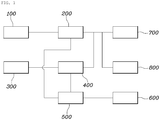
- FIG. 1 is a schematic diagram illustrating the overall configuration of an apparatus for controlling a converter of an eco-friendly vehicle according to an embodiment of the present disclosure
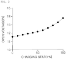
- FIG. 2 is a diagram illustrating open-voltage information for each charging state of an auxiliary battery stored in a database
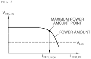
- FIG. 3 is a diagram illustrating power information generated from a renewable energy generator stored in a database
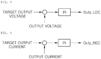
- FIG. 4 is a diagram illustrating a case in which a controller controls the output voltage of a low-voltage conversion converter to be a target output voltage
- FIG. 5 is a diagram illustrating a case in which a controller controls the output current of a renewable energy conversion converter to be a target output current.
- an apparatus for controlling a converter of an eco-friendly vehicle includes a high-voltage battery 100, a low-voltage conversion converter 200, a renewable energy generator 300, a renewable energy conversion converter 400, and a controller 500, and may further include a database 600 according to the embodiment.
- a detailed configuration of the apparatus for controlling the converter of the eco-friendly vehicle according to an embodiment of the present disclosure will be described in more detail.
- the high-voltage battery 100 serves as an energy supply source that supplies power for driving a motor to a high-output large-capacity battery, charges an auxiliary battery, and supplies power to an electric load of the vehicle.
- the high-voltage battery 100 may include a plurality of battery cells, and may have a sum of the total output voltage of the respective battery cells as an output voltage thereof, thereby outputting high-voltage power of several hundred volts or more.
- the low-voltage conversion converter 200 serves to convert the power supplied from the high-voltage battery 100 into a low voltage in order to provide power to at least one of an auxiliary battery 800 and an electric load 700 of the vehicle.
- the low-voltage conversion converter 200 reduces the high-voltage power supplied from the high-voltage battery 100 to a voltage of 12V to provide the reduced voltage to the auxiliary battery 800 and the electric load 700.
- the electric load 700 may include a battery and a generator
- the renewable energy generator 300 serves to generate power using renewable energy including solar light. According to the embodiment, the renewable energy generator 300 may generate energy using solar light by a solar roof or the like installed on the upper portion of the vehicle, and according to another embodiment, may generate energy through thermoelectric power generation or the like. The power generated by the renewable energy generator 300 may be used to charge the battery of the vehicle or to drive the electric load or the like thereof.
- the renewable energy conversion converter 400 serves to convert the power supplied from the renewable energy generator in order to provide power to at least one of the auxiliary battery and the electric load of the vehicle. That is, the renewable energy conversion converter 400 converts the voltage and provides the converted voltage in such a manner that the power generated by the renewable energy generator 300 conforms to the specifications of the auxiliary battery 800 and the electric load 700 used in the vehicle.
- the controller 500 serves to control the output current of the low-voltage conversion converter 200 and the output current of the renewable energy conversion converter 400. Through such control, the controller 500 causes the output current of the low-voltage conversion converter 200 and the output current of the renewable energy conversion converter 400 to be provided simultaneously in order to charge the auxiliary battery 800 of the vehicle, thereby further improving the fuel efficiency of the vehicle.
- the database 600 may store open-voltage information for each charging state of the auxiliary battery and power information generated from the renewable energy generator.
- FIG. 2 is a diagram illustrating open-voltage information for each charging state of the auxiliary battery stored in the database
- FIG. 3 is a diagram illustrating power information generated from the renewable energy generator stored in the database.
- the horizontal axis represents the charging state of the auxiliary battery
- the vertical axis represents an open circuit voltage when the auxiliary battery is in a corresponding charging state. For example, when the charging state is 50 %, the open-voltage of the auxiliary battery is about 12V. When the charging state is 100%, the open-voltage of the auxiliary battery is about 14V.
- the database 600 may include the power information generated from the renewable energy generator 300 as illustrated in FIG. 3 .
- the power information may include an amount of the power generated by the renewable energy generator 300 and voltage and current values input to the renewable energy conversion converter 400 based on the amount of the generated power.
- the graph curve represents power generated by the renewable energy generator 300, and the horizontal axis and the vertical axis represent current and voltage values input to the renewable energy conversion converter 400 according to the amount of the generated power.
- the database 600 stores the open-voltage information for each charging state of the auxiliary battery and the power information generated from the renewable energy generator, and the controller 500 may control the output of each of the low-voltage conversion converter 200 and the renewable energy conversion converter 400 using the information stored in the database 600.
- the characteristics of the controller 500 that causes the output current of the low-voltage conversion converter 200 and the output current of the renewable energy conversion converter 400 to be simultaneously provided to the auxiliary battery 800 of the vehicle will be described in more detail.
- the controller 500 may control the output voltage of the low-voltage conversion converter 200 to be the open circuit voltage corresponding to a target charging state of the auxiliary battery 800 based on the information stored in the database 600.
- the controller 500 may cause the output voltage of the low-voltage conversion converter 200 to reach the open-voltage corresponding to the target charging state of the auxiliary battery 800 through a proportional integral control method. For example, when the target charging state of the auxiliary battery 800 is set to 100 %, the open circuit voltage of the auxiliary battery 800 in the corresponding charging state is about 14V as illustrated in FIG. 4 .
- the controller 500 may control the low-voltage conversion converter 200 so that the high voltage supplied from the high-voltage battery 100 is reduced to 14V to be output.
- the controller 500 may control the low-voltage conversion converter 200 in such a manner that the high voltage supplied from the high-voltage battery 110 is reduced to the open circuit voltage corresponding to the target charging state of the auxiliary battery 800 based on the information stored in the database 600.
- Duty_LCD denotes duty that allows an output voltage of the low-voltage conversion converter to reach a target output voltage.
- the controller 500 may derive maximum power amount information generated from the renewable energy generator 300 based on the information stored in the database 600 and the current and voltage values input to the renewable energy conversion converter 400 according to the generated maximum power amount information, and may derive a target output voltage of the renewable energy conversion converter 400 using the derived current and voltage values and the output voltage value of the low-voltage conversion converter 200.
- the renewable energy conversion converter 400 is a step-down type converter
- the voltage value input to the renewable energy conversion converter 400 may be larger than the output voltage value of the low-voltage conversion converter 200.
- the output voltage of the low-voltage conversion converter 200 may be a value that reaches the open circuit voltage corresponding to the target charging state of the auxiliary battery 800.
- the controller 500 may control the output current of the renewable energy conversion converter 400 to reach the target output current based on the derived target output current value. According to the embodiment, as illustrated in FIG. 5 , the controller 500 may control the output current of the renewable energy conversion converter 400 to reach the target output current through a proportional integral control method.
- Duty_REC denotes duty that allows an output current of the renewable energy conversion converter to reach a target output current.
- FIG. 6 is a diagram illustrating a case in which the auxiliary battery is charged to the target charging state through the output current of the low-voltage conversion converter and the output current of the renewable energy conversion converter, in the apparatus for controlling the converter of the eco-friendly vehicle according to an embodiment of the present disclosure.
- the controller 500 may cause the output current of the renewable energy conversion converter 400 to reach the target output current, and may cause the output current of the low-voltage conversion converter 200 and the output current of the renewable energy conversion converter 400 to be simultaneously provided to the auxiliary battery until the auxiliary battery 800 reaches the target charging state.
- the present disclosure as illustrated in FIG.
- the power generated from the renewable energy generator 300 may be converted through the renewable energy conversion converter 400 to be used to charge the auxiliary battery 800, and the output current of the low-voltage conversion converter 200 may be reduced by the output current of the renewable energy conversion converter 400, thereby further improving the fuel efficiency of the vehicle.
- V LDC denotes an output voltage of the low-voltage conversion converter
- V BAT_TARGET denotes an open circuit voltage corresponding to a target charging state of the auxiliary battery
- V BAT denotes a voltage of the auxiliary battery
- I LDC denotes an output current of the low-voltage conversion converter
- I BAT denotes a current applied to an auxiliary battery
- I LOAD denotes a current applied to an electric load
- I REC denotes an output current of the renewable energy conversion converter
- I REC_TARGET denotes a target output current of the renewable energy conversion converter.
- controller 500 may stop the operation of the renewable energy conversion converter 400 after the auxiliary battery reaches the target charging state.
- the controller 500 may operate at least one of the low-voltage conversion converter 200 and the renewable energy conversion converter 400 while the vehicle is stopped or traveling. That is, according to the embodiment, the controller 500 may operate only the renewable energy conversion converter 400 during the stop of the vehicle, and according to another embodiment, may simultaneously operate the low-voltage conversion converter 200 and the renewable energy conversion converter 400 during the stopping of the vehicle.
- operating the renewable energy conversion converter 400 may mean that the power generated from the renewable energy generator 300 is used
- operating the low-voltage conversion converter 200 may mean that the power provided from the high-voltage battery 100 is used.
- the controller 550 may simultaneously operate the low-voltage conversion converter 200 and the renewable energy conversion converter 400 even while the vehicle is traveling.
- FIG. 7 is a flowchart illustrating a method for controlling a converter of an eco-friendly vehicle according to an embodiment of the present disclosure.
- the method for controlling the converter of the eco-friendly vehicle according to an embodiment of the present disclosure may include setting an output voltage of a low-voltage conversion converter to an open circuit voltage corresponding to a target charging state of an auxiliary battery, deriving maximum power amount information generated from a renewable energy generator based on information stored in a database and current and voltage values input to a renewable energy conversion converter based on the generated maximum power amount information and deriving a target output current of the renewable energy conversion converter using the derived current and voltage values and the output voltage value of the low-voltage conversion converter, and causing an output current of the renewable energy conversion converter to reach the target output current of the renewable energy conversion converter.
- the method for controlling the converter of the eco-friendly vehicle may further include causing an output current of the low-voltage conversion converter and the output current of the renewable energy conversion converter to be simultaneously provided to the auxiliary battery until the auxiliary battery reaches the target charging state, and causing an operation of the renewable energy conversion converter to be stopped after the auxiliary battery reaches the target charging state.
- detailed description of the operations performed by the controller are the same as the detailed description of the controller of the above-described method for controlling the converter of the eco-friendly vehicle, and thus will be omitted.
Abstract
Description
- The present disclosure relates to an apparatus and A method for controlling a converter of an eco-friendly vehicle, and more particularly, to an apparatus and a method for controlling a converter of an eco-friendly vehicle, capable of controlling a low-voltage conversion converter and a renewable energy conversion converter for converting power generated.
- Generally, an eco-friendly vehicle includes a high-voltage battery for supplying driving power and an auxiliary battery for supplying power to an electric load. When the voltage of the auxiliary battery does not exceed a reference value under the control of a host controller, a low-voltage DC-DC converter (LDC) connected to the auxiliary battery and the electric load lowers the voltage of the high-voltage battery to charge the auxiliary battery.
- In order to improve the fuel efficiency of the vehicle, research for applying technology including solar power generation and thermoelectric power generation to generate power using renewable energy to the eco-friendly vehicle is actively being conducted. In this way, in the eco-friendly vehicle to which energy generated through the renewable energy is applied, a renewable energy conversion converter is required to use the power generated through the renewable energy to charge the battery of the vehicle or to drive the electric load thereof.
- However, conventionally, in the eco-friendly vehicle to which the LDC and the renewable energy conversion converter are applied, when the LDC and the renewable energy conversion converter are operated simultaneously, a phenomenon in which the load current tends to be diverted to the converter having a large output voltage occurs. More specifically, when the load current is diverted to the LDC, it is impossible to transfer the energy generated through the renewable energy, and when the load current is diverted to the renewable energy conversion converter, an excessive current flows to the renewable energy conversion converter so that the output is limited. That is, conventionally, there is a limit in that the output of the LDC and the output of the renewable energy conversion converter cannot be used simultaneously.
- The present disclosure has been made in order to solve the above-mentioned problems in the prior art and an aspect of the present disclosure is to provide an apparatus and method for controlling a converter of an eco-friendly vehicle, which may control an output voltage of a low-voltage conversion converter and an output current of a renewable energy conversion converter to simultaneously use the output of the low-voltage conversion converter and the output of the renewable energy conversion converter and thereby may further improve the fuel efficiency of the vehicle.
- In accordance with an aspect of the present disclosure, an apparatus for controlling a converter of an eco-friendly vehicle includes: a high-voltage battery; a low-voltage conversion converter configured to convert power supplied from the high-voltage battery into a low voltage to provide power to at least one of an auxiliary battery of the vehicle and an electric load thereof; a renewable energy generator configured to generate power using renewable energy including solar light; a renewable energy conversion converter configured to convert the power supplied from the renewable energy generator to provide power to the at least one of the auxiliary battery and the electric load; and a controller configured to control an output voltage value of the low-voltage conversion converter and an output current of the renewable energy conversion converter.
- Here, the apparatus may further include a database configured to store open-voltage information for each charging state of the auxiliary battery and power information generated from the renewable energy generator.
- The controller may control the output voltage of the low-voltage conversion converter to be an open circuit voltage corresponding to a target charging state of the auxiliary battery based on the information stored in the database.
- The controller may derive maximum power amount information generated from the renewable energy generator based on information stored in the database and current and voltage values input to the renewable energy conversion converter based on the generated maximum power amount information, and may derive a target output current of the renewable energy conversion converter using the derived current and voltage values and the output voltage value of the low-voltage conversion converter.
- The controller may cause the output current of the renewable energy conversion converter to reach the target output current of the renewable energy conversion converter.
- The controller may cause an output current of the low-voltage conversion converter and the output current of the renewable energy conversion converter to be simultaneously provided to the auxiliary battery until the auxiliary battery reaches a target charging state.
- The controller may cause an operation of the renewable energy conversion converter to be stopped after the auxiliary battery reaches the target charging state.
- The controller may cause at least one of the low-voltage conversion converter and the renewable energy conversion converter to be operated during stopping or traveling of the vehicle.
- In accordance with another aspect of the present disclosure, a method for controlling a converter of an eco-friendly vehicle includes: setting an output voltage value of a low-voltage conversion converter to an open circuit voltage corresponding to a target charging state of an auxiliary battery; deriving maximum power amount information generated from a renewable energy generator based on information stored in a database and current and voltage values input to a renewable energy conversion converter based on the generated maximum power amount information, and deriving a target output current of the renewable energy conversion converter using the derived current and voltage values and the output voltage value of the low-voltage conversion converter; and increasing an output current of the renewable energy conversion converter to reach the target output current of the renewable energy conversion converter.
- Here, the method may further include causing an output current of the low-voltage conversion converter and the output current of the renewable energy conversion converter to be simultaneously provided to the auxiliary battery until the auxiliary battery reaches the target charging state; and causing an operation of the renewable energy conversion converter to be stopped after the auxiliary battery reaches the target charging state.
- According to the present disclosure, it is possible to simultaneously use the output of the low-voltage conversion converter and the output of the renewable energy conversion converter by controlling the output voltage of the low-voltage conversion converter and the output current of the renewable energy conversion converter, thereby further improving the fuel efficiency of the vehicle.
- The above and other aspects, features and advantages of the present disclosure will be more apparent from the following detailed description taken in conjunction with the accompanying drawings, in which:
-
FIG. 1 is a schematic diagram illustrating the overall configuration of an apparatus for controlling a converter of an eco-friendly vehicle according to an embodiment of the present disclosure; -
FIG. 2 is a diagram illustrating open-voltage information for each charging state of an auxiliary battery stored in a database, in an apparatus for controlling a converter of an eco-friendly vehicle according to an embodiment of the present disclosure; -
FIG. 3 is a diagram illustrating power information generated from a renewable energy generator stored in a database, in an apparatus for controlling a converter of an eco-friendly vehicle according to an embodiment of the present disclosure; -
FIG. 4 is a diagram illustrating a case in which a controller controls the output voltage of a low-voltage conversion converter to be a target output voltage, in an apparatus for controlling a converter of an eco-friendly vehicle according to an embodiment of the present disclosure; -
FIG. 5 is a diagram illustrating a case in which a controller controls the output current of a renewable energy conversion converter to be a target output current, in an apparatus for controlling a converter of an eco-friendly vehicle according to an embodiment of the present disclosure; -
FIG. 6 is a diagram illustrating a case in which an auxiliary battery is charged to a target charging state through the output current of a low-voltage conversion converter and the output current of a renewable energy conversion converter, in an apparatus for controlling a converter of an eco-friendly vehicle according to an embodiment of the present disclosure; and -
FIG. 7 is a flowchart illustrating a method for controlling a converter of an eco-friendly vehicle according to an embodiment of the present disclosure. - Hereinafter, an apparatus and method for controlling a converter of an eco-friendly vehicle according to one aspect of embodiments of the present disclosure will be described with reference to the accompanying drawings.
-
FIG. 1 is a schematic diagram illustrating the overall configuration of an apparatus for controlling a converter of an eco-friendly vehicle according to an embodiment of the present disclosure,FIG. 2 is a diagram illustrating open-voltage information for each charging state of an auxiliary battery stored in a database,FIG. 3 is a diagram illustrating power information generated from a renewable energy generator stored in a database,FIG. 4 is a diagram illustrating a case in which a controller controls the output voltage of a low-voltage conversion converter to be a target output voltage, andFIG. 5 is a diagram illustrating a case in which a controller controls the output current of a renewable energy conversion converter to be a target output current. - As illustrated in
FIG. 1 , an apparatus for controlling a converter of an eco-friendly vehicle according to an embodiment of the present disclosure includes a high-voltage battery 100, a low-voltage conversion converter 200, arenewable energy generator 300, a renewableenergy conversion converter 400, and acontroller 500, and may further include adatabase 600 according to the embodiment. Hereinafter, a detailed configuration of the apparatus for controlling the converter of the eco-friendly vehicle according to an embodiment of the present disclosure will be described in more detail. - The high-
voltage battery 100 serves as an energy supply source that supplies power for driving a motor to a high-output large-capacity battery, charges an auxiliary battery, and supplies power to an electric load of the vehicle. Here, the high-voltage battery 100 may include a plurality of battery cells, and may have a sum of the total output voltage of the respective battery cells as an output voltage thereof, thereby outputting high-voltage power of several hundred volts or more. - The low-
voltage conversion converter 200 serves to convert the power supplied from the high-voltage battery 100 into a low voltage in order to provide power to at least one of anauxiliary battery 800 and anelectric load 700 of the vehicle. For example, when theauxiliary battery 800 and theelectric load 700 of 12V in the vehicle are used, the low-voltage conversion converter 200 reduces the high-voltage power supplied from the high-voltage battery 100 to a voltage of 12V to provide the reduced voltage to theauxiliary battery 800 and theelectric load 700. Here, theelectric load 700 may include a battery and a generator - The
renewable energy generator 300 serves to generate power using renewable energy including solar light. According to the embodiment, therenewable energy generator 300 may generate energy using solar light by a solar roof or the like installed on the upper portion of the vehicle, and according to another embodiment, may generate energy through thermoelectric power generation or the like. The power generated by therenewable energy generator 300 may be used to charge the battery of the vehicle or to drive the electric load or the like thereof. - The renewable
energy conversion converter 400 serves to convert the power supplied from the renewable energy generator in order to provide power to at least one of the auxiliary battery and the electric load of the vehicle. That is, the renewableenergy conversion converter 400 converts the voltage and provides the converted voltage in such a manner that the power generated by therenewable energy generator 300 conforms to the specifications of theauxiliary battery 800 and theelectric load 700 used in the vehicle. - The
controller 500 serves to control the output current of the low-voltage conversion converter 200 and the output current of the renewableenergy conversion converter 400. Through such control, thecontroller 500 causes the output current of the low-voltage conversion converter 200 and the output current of the renewableenergy conversion converter 400 to be provided simultaneously in order to charge theauxiliary battery 800 of the vehicle, thereby further improving the fuel efficiency of the vehicle. - The
database 600 may store open-voltage information for each charging state of the auxiliary battery and power information generated from the renewable energy generator. -
FIG. 2 is a diagram illustrating open-voltage information for each charging state of the auxiliary battery stored in the database,FIG. 3 is a diagram illustrating power information generated from the renewable energy generator stored in the database. Referring toFIG.2 , the horizontal axis represents the charging state of the auxiliary battery, and the vertical axis represents an open circuit voltage when the auxiliary battery is in a corresponding charging state. For example, when the charging state is 50 %, the open-voltage of the auxiliary battery is about 12V. When the charging state is 100%, the open-voltage of the auxiliary battery is about 14V. - In addition, the
database 600 may include the power information generated from therenewable energy generator 300 as illustrated inFIG. 3 . Here, the power information may include an amount of the power generated by therenewable energy generator 300 and voltage and current values input to the renewableenergy conversion converter 400 based on the amount of the generated power. Referring toFIG. 3 , the graph curve represents power generated by therenewable energy generator 300, and the horizontal axis and the vertical axis represent current and voltage values input to the renewableenergy conversion converter 400 according to the amount of the generated power. - As described above, the
database 600 stores the open-voltage information for each charging state of the auxiliary battery and the power information generated from the renewable energy generator, and thecontroller 500 may control the output of each of the low-voltage conversion converter 200 and the renewableenergy conversion converter 400 using the information stored in thedatabase 600. Hereinafter, the characteristics of thecontroller 500 that causes the output current of the low-voltage conversion converter 200 and the output current of the renewableenergy conversion converter 400 to be simultaneously provided to theauxiliary battery 800 of the vehicle will be described in more detail. - First, as illustrated in
FIG. 4 , thecontroller 500 may control the output voltage of the low-voltage conversion converter 200 to be the open circuit voltage corresponding to a target charging state of theauxiliary battery 800 based on the information stored in thedatabase 600. According to the embodiment, thecontroller 500 may cause the output voltage of the low-voltage conversion converter 200 to reach the open-voltage corresponding to the target charging state of theauxiliary battery 800 through a proportional integral control method. For example, when the target charging state of theauxiliary battery 800 is set to 100 %, the open circuit voltage of theauxiliary battery 800 in the corresponding charging state is about 14V as illustrated inFIG. 4 . Accordingly, thecontroller 500 may control the low-voltage conversion converter 200 so that the high voltage supplied from the high-voltage battery 100 is reduced to 14V to be output. In this manner, when the target charging state of theauxiliary battery 800 is set, thecontroller 500 may control the low-voltage conversion converter 200 in such a manner that the high voltage supplied from the high-voltage battery 110 is reduced to the open circuit voltage corresponding to the target charging state of theauxiliary battery 800 based on the information stored in thedatabase 600. InFIG. 4 , Duty_LCD denotes duty that allows an output voltage of the low-voltage conversion converter to reach a target output voltage. - When the output voltage of the low-
voltage conversion converter 200 reaches the open circuit voltage corresponding to the target charging state of theauxiliary battery 800, thecontroller 500 may derive maximum power amount information generated from therenewable energy generator 300 based on the information stored in thedatabase 600 and the current and voltage values input to the renewableenergy conversion converter 400 according to the generated maximum power amount information, and may derive a target output voltage of the renewableenergy conversion converter 400 using the derived current and voltage values and the output voltage value of the low-voltage conversion converter 200. At this time, since the renewableenergy conversion converter 400 is a step-down type converter, the voltage value input to the renewableenergy conversion converter 400 may be larger than the output voltage value of the low-voltage conversion converter 200. Here, the output voltage of the low-voltage conversion converter 200 may be a value that reaches the open circuit voltage corresponding to the target charging state of theauxiliary battery 800. - In addition, as illustrated in
FIG. 5 , thecontroller 500 may control the output current of the renewableenergy conversion converter 400 to reach the target output current based on the derived target output current value. According to the embodiment, as illustrated inFIG. 5 , thecontroller 500 may control the output current of the renewableenergy conversion converter 400 to reach the target output current through a proportional integral control method. InFIG. 5 , Duty_REC denotes duty that allows an output current of the renewable energy conversion converter to reach a target output current. -
FIG. 6 is a diagram illustrating a case in which the auxiliary battery is charged to the target charging state through the output current of the low-voltage conversion converter and the output current of the renewable energy conversion converter, in the apparatus for controlling the converter of the eco-friendly vehicle according to an embodiment of the present disclosure. Referring toFIG. 6 , when the output of the low-voltage conversion converter 200 reaches the open circuit voltage corresponding to the target charging state of the auxiliary battery, thecontroller 500 may cause the output current of the renewableenergy conversion converter 400 to reach the target output current, and may cause the output current of the low-voltage conversion converter 200 and the output current of the renewableenergy conversion converter 400 to be simultaneously provided to the auxiliary battery until theauxiliary battery 800 reaches the target charging state. As described above, in the present disclosure as illustrated inFIG. 6 , the power generated from therenewable energy generator 300 may be converted through the renewableenergy conversion converter 400 to be used to charge theauxiliary battery 800, and the output current of the low-voltage conversion converter 200 may be reduced by the output current of the renewableenergy conversion converter 400, thereby further improving the fuel efficiency of the vehicle. - In
FIG. 6 , VLDC denotes an output voltage of the low-voltage conversion converter, VBAT_TARGET denotes an open circuit voltage corresponding to a target charging state of the auxiliary battery, VBAT denotes a voltage of the auxiliary battery, ILDC denotes an output current of the low-voltage conversion converter, IBAT denotes a current applied to an auxiliary battery, ILOAD denotes a current applied to an electric load, IREC denotes an output current of the renewable energy conversion converter, and IREC_TARGET denotes a target output current of the renewable energy conversion converter. - In addition, the
controller 500 may stop the operation of the renewableenergy conversion converter 400 after the auxiliary battery reaches the target charging state. - The
controller 500 may operate at least one of the low-voltage conversion converter 200 and the renewableenergy conversion converter 400 while the vehicle is stopped or traveling. That is, according to the embodiment, thecontroller 500 may operate only the renewableenergy conversion converter 400 during the stop of the vehicle, and according to another embodiment, may simultaneously operate the low-voltage conversion converter 200 and the renewableenergy conversion converter 400 during the stopping of the vehicle. Here, operating the renewableenergy conversion converter 400 may mean that the power generated from therenewable energy generator 300 is used, and operating the low-voltage conversion converter 200 may mean that the power provided from the high-voltage battery 100 is used. In addition, the controller 550 may simultaneously operate the low-voltage conversion converter 200 and the renewableenergy conversion converter 400 even while the vehicle is traveling. -
FIG. 7 is a flowchart illustrating a method for controlling a converter of an eco-friendly vehicle according to an embodiment of the present disclosure. As illustrated inFIG. 7 , the method for controlling the converter of the eco-friendly vehicle according to an embodiment of the present disclosure may include setting an output voltage of a low-voltage conversion converter to an open circuit voltage corresponding to a target charging state of an auxiliary battery, deriving maximum power amount information generated from a renewable energy generator based on information stored in a database and current and voltage values input to a renewable energy conversion converter based on the generated maximum power amount information and deriving a target output current of the renewable energy conversion converter using the derived current and voltage values and the output voltage value of the low-voltage conversion converter, and causing an output current of the renewable energy conversion converter to reach the target output current of the renewable energy conversion converter. The method for controlling the converter of the eco-friendly vehicle according to an embodiment of the present disclosure may further include causing an output current of the low-voltage conversion converter and the output current of the renewable energy conversion converter to be simultaneously provided to the auxiliary battery until the auxiliary battery reaches the target charging state, and causing an operation of the renewable energy conversion converter to be stopped after the auxiliary battery reaches the target charging state. In the method for controlling the converter of the eco-friendly vehicle according to the present disclosure, detailed description of the operations performed by the controller are the same as the detailed description of the controller of the above-described method for controlling the converter of the eco-friendly vehicle, and thus will be omitted.
Claims (10)
- An apparatus for controlling a converter of an eco-friendly vehicle, the apparatus comprising:a high-voltage battery;a low-voltage conversion converter configured to convert power supplied from the high-voltage battery into a low voltage to provide power to at least one of an auxiliary battery of the vehicle or an electric load of the vehicle;a renewable energy generator configured to generate power using renewable energy including solar light;a renewable energy conversion converter configured to convert the power supplied from the renewable energy generator to provide power to the at least one of the auxiliary battery and the electric load; anda controller configured to control an output voltage value of the low-voltage conversion converter and an output current of the renewable energy conversion converter.
- The apparatus according to claim 1, further comprising:
a database configured to store open-voltage information for each charging state of the auxiliary battery and power information generated from the renewable energy generator. - The apparatus according to claim 2, wherein the controller controls the output voltage value of the low-voltage conversion converter to be an open circuit voltage corresponding to a target charging state of the auxiliary battery based on the open-voltage information stored in the database.
- The apparatus according to claim 2, wherein the controller derives maximum power amount information generated from the renewable energy generator based on the power information stored in the database and current and voltage values input to the renewable energy conversion converter based on the generated maximum power amount information, and derives a target output current of the renewable energy conversion converter using the derived current and voltage values and the output voltage value of the low-voltage conversion converter.
- The apparatus according to claim 4, wherein the controller increases the output current of the renewable energy conversion converter to reach the target output current of the renewable energy conversion converter.
- The apparatus according to claim 1, wherein the controller simultaneously provides an output current of the low-voltage conversion converter and the output current of the renewable energy conversion converter to the auxiliary battery until the auxiliary battery reaches a target charging state.
- The apparatus according to claim 6, wherein the controller ends an operation of the renewable energy conversion converter after the auxiliary battery reaches the target charging state.
- The apparatus according to claim 1, wherein the controller operates at least one of the low-voltage conversion converter and the renewable energy conversion converter during stopping or traveling of the vehicle.
- A method for controlling a converter of an eco-friendly vehicle, the method comprising steps of:setting an output voltage value of a low-voltage conversion converter to an open circuit voltage corresponding to a target charging state of an auxiliary battery;deriving maximum power amount information generated from a renewable energy generator based on information stored in a database and current and voltage values input to a renewable energy conversion converter based on the generated maximum power amount information, and deriving a target output current of the renewable energy conversion converter using the derived current and voltage values and the output voltage value of the low-voltage conversion converter; andincreasing an output current of the renewable energy conversion converter to reach the target output current of the renewable energy conversion converter.
- The method according to claim 9, further comprising steps of:supplying an output current of the low-voltage conversion converter and the output current of the renewable energy conversion converter, simultaneously, to the auxiliary battery until the auxiliary battery reaches the target charging state; andstopping an operation of the renewable energy conversion converter after the auxiliary battery reaches the target charging state.
Applications Claiming Priority (1)
| Application Number | Priority Date | Filing Date | Title |
|---|---|---|---|
| KR1020180018499A KR102518182B1 (en) | 2018-02-14 | 2018-02-14 | Apparatus for controlling converter of green car and method thereof |
Publications (1)
| Publication Number | Publication Date |
|---|---|
| EP3528358A1 true EP3528358A1 (en) | 2019-08-21 |
Family
ID=63407144
Family Applications (1)
| Application Number | Title | Priority Date | Filing Date |
|---|---|---|---|
| EP18191014.2A Pending EP3528358A1 (en) | 2018-02-14 | 2018-08-27 | Apparatus and method for controlling converter of eco-friendly vehicle |
Country Status (3)
| Country | Link |
|---|---|
| US (1) | US10944286B2 (en) |
| EP (1) | EP3528358A1 (en) |
| KR (1) | KR102518182B1 (en) |
Citations (4)
| Publication number | Priority date | Publication date | Assignee | Title |
|---|---|---|---|---|
| JP2014023211A (en) * | 2012-07-13 | 2014-02-03 | Denso Corp | Charger |
| US20140095018A1 (en) * | 2012-09-28 | 2014-04-03 | GM Global Technology Operations LLC | Methods And Vehicle Systems For Selectively Using Energy Obtained From A Solar Subsystem |
| US20170166079A1 (en) * | 2015-12-10 | 2017-06-15 | Volkswagen Ag | Electric voltage system and method for distributing electrical power in an electric voltage system |
| US20170267113A1 (en) * | 2016-03-16 | 2017-09-21 | Toyota Jidosha Kabushiki Kaisha | Solar battery system |
Family Cites Families (61)
| Publication number | Priority date | Publication date | Assignee | Title |
|---|---|---|---|---|
| KR100260147B1 (en) * | 1996-10-29 | 2000-08-01 | 정몽규 | Cruise control system and method for solar car |
| JP4466591B2 (en) * | 2006-03-13 | 2010-05-26 | 日産自動車株式会社 | Vehicle drive control device |
| US7446505B2 (en) * | 2006-08-24 | 2008-11-04 | Symbol Technologies, Inc. | System and method for calculating a state of charge of a battery |
| JP2008241358A (en) * | 2007-03-26 | 2008-10-09 | Sanyo Electric Co Ltd | Full capacity detection method of battery |
| FR2916049B1 (en) * | 2007-05-11 | 2009-07-03 | Commissariat Energie Atomique | METHOD FOR DIAGNOSING DEFECTIVE ELEMENTS IN AN AUTONOMOUS SYSTEM POWERED BY AN INTERMITTENT POWER SOURCE |
| JP2012515526A (en) * | 2009-01-15 | 2012-07-05 | フィスカー オートモーティブ インク. | Solar power management for vehicles |
| US20100198424A1 (en) * | 2009-01-30 | 2010-08-05 | Toru Takehara | Method for reconfigurably connecting photovoltaic panels in a photovoltaic array |
| CN201754409U (en) * | 2010-06-30 | 2011-03-02 | 比亚迪股份有限公司 | Solar battery terminal box |
| US8482255B2 (en) * | 2010-08-26 | 2013-07-09 | Ford Global Technologies, Llc | Method and system for charging an auxilary battery in a plug-in electric vehicle |
| JP5577967B2 (en) * | 2010-09-06 | 2014-08-27 | 株式会社オートネットワーク技術研究所 | Vehicle power supply control device |
| US20120075898A1 (en) * | 2010-09-28 | 2012-03-29 | Astec International Limited | Photovoltaic Power Converters and Closed Loop Maximum Power Point Tracking |
| US8775105B2 (en) * | 2010-10-28 | 2014-07-08 | GM Global Technology Operations LLC | Onboard adaptive battery core temperature estimation |
| US9285816B2 (en) * | 2011-01-28 | 2016-03-15 | Prakash Easwaran | Harvesting power from DC (direct current) sources |
| WO2012132949A1 (en) * | 2011-03-30 | 2012-10-04 | 三洋電機株式会社 | Current collection box |
| JP5903565B2 (en) * | 2011-03-30 | 2016-04-13 | パナソニックIpマネジメント株式会社 | Power conversion system |
| US9118191B2 (en) * | 2011-08-29 | 2015-08-25 | Samsung Sdi Co., Ltd. | Cell balancing method, cell balancing device, and energy storage system including the cell balancing device |
| EP2752329A4 (en) * | 2011-08-30 | 2015-09-23 | Toyota Motor Co Ltd | Power supply system for vehicle |
| KR20130053081A (en) * | 2011-11-15 | 2013-05-23 | 현대자동차주식회사 | Sun roof having solar cells |
| KR101648889B1 (en) * | 2011-12-06 | 2016-08-18 | 삼성에스디아이 주식회사 | Apparatus for controlling battery pack, and energy storage system including the battery pack |
| KR101283892B1 (en) | 2011-12-07 | 2013-07-08 | 기아자동차주식회사 | Dc-dc converter control system for green car and method thereof |
| DE102012002185B4 (en) * | 2012-02-07 | 2019-11-07 | Sew-Eurodrive Gmbh & Co Kg | Energy recovery system with energy storage, method for operating an energy recovery system |
| US9350175B2 (en) * | 2012-04-17 | 2016-05-24 | General Electric Company | Input relay architecture for rectifying power converters and suitable for AC or DC source power |
| US8981727B2 (en) * | 2012-05-21 | 2015-03-17 | General Electric Company | Method and apparatus for charging multiple energy storage devices |
| JP5673633B2 (en) * | 2012-06-01 | 2015-02-18 | 株式会社デンソー | In-vehicle charging controller |
| JP5582173B2 (en) * | 2012-06-22 | 2014-09-03 | 株式会社デンソー | Charger |
| US9306443B2 (en) * | 2012-09-13 | 2016-04-05 | Richtek Technology Corporation, R.O.C | Analog photovoltaic power circuit with auto zero calibration |
| US9172259B2 (en) * | 2012-11-29 | 2015-10-27 | Samsung Sdi Co., Ltd. | Apparatus for managing battery, and energy storage system |
| KR101449182B1 (en) * | 2012-12-21 | 2014-10-10 | 현대자동차주식회사 | A Structure Unit of Solar Loop Unified with Glass |
| CN105073481B (en) * | 2012-12-21 | 2017-03-08 | 丰田自动车株式会社 | Battery charge controller using Vehicular solar battery |
| CN103248067B (en) * | 2013-04-27 | 2016-03-02 | 京东方科技集团股份有限公司 | The low voltage ride through control method of photovoltaic combining inverter and device |
| KR20150029204A (en) * | 2013-09-09 | 2015-03-18 | 삼성에스디아이 주식회사 | Battery pack, apparatus including battery pack, and method of managing battery pack |
| ES2535059B1 (en) * | 2013-10-31 | 2016-02-09 | Control Techniques Iberia S.A. | Method and system to control a power supply to a load |
| KR20150073291A (en) * | 2013-12-20 | 2015-07-01 | 엘에스산전 주식회사 | Power conversion device |
| JP6327106B2 (en) * | 2014-01-10 | 2018-05-23 | 住友電気工業株式会社 | Conversion device |
| WO2015107706A1 (en) * | 2014-01-20 | 2015-07-23 | 三菱電機株式会社 | Power conversion device |
| US20170070081A1 (en) * | 2014-03-06 | 2017-03-09 | Robert Bosch Gmbh | Hybrid storage system |
| KR101655555B1 (en) * | 2014-10-31 | 2016-09-22 | 현대자동차주식회사 | System for using solar cell and the method the same |
| KR101637713B1 (en) * | 2014-10-31 | 2016-07-20 | 현대자동차주식회사 | Roof panel having solar cell of vehicle |
| KR101646371B1 (en) * | 2014-11-03 | 2016-08-05 | 현대자동차주식회사 | Solar power generator for Windows |
| KR101637717B1 (en) * | 2014-11-04 | 2016-07-20 | 현대자동차주식회사 | Electric interconnection system for solar cell of vehicle roof |
| KR20160068338A (en) * | 2014-12-05 | 2016-06-15 | 현대자동차주식회사 | A body-unity type solar cell for automobile |
| KR101655625B1 (en) * | 2014-12-24 | 2016-09-07 | 현대자동차주식회사 | Apparatus and Method for converting power |
| KR101637809B1 (en) * | 2015-02-05 | 2016-07-07 | 현대자동차주식회사 | Rear tray for vehicle having energy harvesting elements |
| KR101646447B1 (en) * | 2015-02-09 | 2016-08-05 | 현대자동차주식회사 | A vacuum ring and a method for producing laminated assembly with it |
| JP6414491B2 (en) * | 2015-03-06 | 2018-10-31 | 住友電気工業株式会社 | Conversion device |
| JP6586290B2 (en) * | 2015-04-23 | 2019-10-02 | 本田技研工業株式会社 | Power storage control device, transport equipment, and power storage control method |
| EP3118965B1 (en) * | 2015-07-15 | 2019-10-30 | Hyundai Motor Company | Apparatus for controlling supply of power of battery |
| KR102415122B1 (en) * | 2015-08-20 | 2022-06-30 | 삼성에스디아이 주식회사 | Battery system |
| KR101755911B1 (en) * | 2015-12-02 | 2017-07-07 | 현대자동차주식회사 | Apparatus for estimating soc of lithium ion battery and method thereof |
| JP6662035B2 (en) * | 2015-12-25 | 2020-03-11 | 富士電機株式会社 | Control device |
| WO2017210402A1 (en) * | 2016-06-02 | 2017-12-07 | The Penn State Research Foundation | Self-balancing photovoltaic energy storage system and method |
| US20170359016A1 (en) * | 2016-06-08 | 2017-12-14 | Hyundai Motor Company | Solar cell system integrated with window glass and blind |
| KR101876067B1 (en) * | 2016-10-10 | 2018-07-06 | 현대자동차주식회사 | Wiring System for Sunroof of the Vehicle |
| JP6897250B2 (en) * | 2017-04-07 | 2021-06-30 | 富士通株式会社 | Electrolysis system, electrolysis control device and control method of electrolysis system |
| KR102428658B1 (en) * | 2017-06-09 | 2022-08-03 | 현대자동차주식회사 | Power conversion apparatus, method for controlling the same and vehicle including the same |
| KR102440687B1 (en) * | 2017-10-13 | 2022-09-05 | 현대자동차주식회사 | solar power generation sliding window/door assembly |
| JP6919506B2 (en) * | 2017-11-02 | 2021-08-18 | 富士通株式会社 | Electrolysis system, electrolysis control device and control method of electrolysis system |
| KR102440522B1 (en) * | 2017-12-28 | 2022-09-06 | 현대자동차주식회사 | Apparatus and Method for controlling charge capacity variably using external energy source |
| KR20190125704A (en) * | 2018-04-30 | 2019-11-07 | 현대자동차주식회사 | Vehicle and controlling method thereof |
| KR20190136185A (en) * | 2018-05-30 | 2019-12-10 | 현대자동차주식회사 | Vehicle power and controlling method thereof |
| CN109038780A (en) * | 2018-06-29 | 2018-12-18 | 华为技术有限公司 | A kind of photovoltaic system |
-
2018
- 2018-02-14 KR KR1020180018499A patent/KR102518182B1/en active IP Right Grant
- 2018-08-27 EP EP18191014.2A patent/EP3528358A1/en active Pending
- 2018-08-28 US US16/115,093 patent/US10944286B2/en active Active
Patent Citations (4)
| Publication number | Priority date | Publication date | Assignee | Title |
|---|---|---|---|---|
| JP2014023211A (en) * | 2012-07-13 | 2014-02-03 | Denso Corp | Charger |
| US20140095018A1 (en) * | 2012-09-28 | 2014-04-03 | GM Global Technology Operations LLC | Methods And Vehicle Systems For Selectively Using Energy Obtained From A Solar Subsystem |
| US20170166079A1 (en) * | 2015-12-10 | 2017-06-15 | Volkswagen Ag | Electric voltage system and method for distributing electrical power in an electric voltage system |
| US20170267113A1 (en) * | 2016-03-16 | 2017-09-21 | Toyota Jidosha Kabushiki Kaisha | Solar battery system |
Also Published As
| Publication number | Publication date |
|---|---|
| KR102518182B1 (en) | 2023-04-07 |
| KR20190098483A (en) | 2019-08-22 |
| US20190252897A1 (en) | 2019-08-15 |
| US10944286B2 (en) | 2021-03-09 |
Similar Documents
| Publication | Publication Date | Title |
|---|---|---|
| KR102493179B1 (en) | Multi-source energy storage system and energy management and control method | |
| CN102088197B (en) | Method for controlling charging voltage of 12V auxiliary battery for hybrid vehicle | |
| US8486570B2 (en) | Apparatus for high efficiency operation of fuel cell systems and method of manufacturing same | |
| US20110084648A1 (en) | Hybrid energy storage system | |
| US10118501B2 (en) | Control method and system for charging high voltage battery of vehicle | |
| US11338689B2 (en) | System and method for controlling vehicle including solar cell | |
| JP5497871B2 (en) | Electric vehicle power supply system and control method thereof | |
| KR102437708B1 (en) | Generating system and method for fuel cell vehicle | |
| KR101683504B1 (en) | Charging apparatus of low voltage battery and method thereof | |
| US10618419B2 (en) | Energy storage arrangement comprising multiple energy stores | |
| CN103475045A (en) | Solar power system for vehicle and control method of solar power system | |
| US10944286B2 (en) | Apparatus and method for controlling converter of eco-friendly vehicle | |
| JP2021087291A (en) | Solar charging system | |
| KR102532323B1 (en) | Power converting system for vehicle | |
| EP3640175B1 (en) | Decentralized power management in an elevator system | |
| US11305671B2 (en) | Method of controlling electric vehicle and electric vehicle system | |
| JP5849518B2 (en) | Power system | |
| KR20210003977A (en) | Electronic four-wheel drive control method and device according to bidirectional high voltage dc/dc converter of fuel cell electric vehicle | |
| US20240116380A1 (en) | Solar charging system | |
| KR20190142552A (en) | Pulse Width Modulation Dead Time Control Method for High Efficient Inverter of Energy Storage System | |
| EP4287445A1 (en) | Electric vehicle with solar panels | |
| KR20130131604A (en) | High voltage battery dc converting apparatus for vehicle and control method thereof | |
| JP5849517B2 (en) | Power system | |
| JP6787271B2 (en) | Power system | |
| KR20230101256A (en) | Charging system for vehicle and controlling method for the same |
Legal Events
| Date | Code | Title | Description |
|---|---|---|---|
| PUAI | Public reference made under article 153(3) epc to a published international application that has entered the european phase |
Free format text: ORIGINAL CODE: 0009012 |
|
| STAA | Information on the status of an ep patent application or granted ep patent |
Free format text: STATUS: REQUEST FOR EXAMINATION WAS MADE |
|
| 17P | Request for examination filed |
Effective date: 20190510 |
|
| AK | Designated contracting states |
Kind code of ref document: A1 Designated state(s): AL AT BE BG CH CY CZ DE DK EE ES FI FR GB GR HR HU IE IS IT LI LT LU LV MC MK MT NL NO PL PT RO RS SE SI SK SM TR |
|
| AX | Request for extension of the european patent |
Extension state: BA ME |
|
| STAA | Information on the status of an ep patent application or granted ep patent |
Free format text: STATUS: EXAMINATION IS IN PROGRESS |
|
| 17Q | First examination report despatched |
Effective date: 20210701 |
|
| RAP3 | Party data changed (applicant data changed or rights of an application transferred) |
Owner name: HYUNDAI MOTOR COMPANY Owner name: KIA CORPORATION |
|
| STAA | Information on the status of an ep patent application or granted ep patent |
Free format text: STATUS: EXAMINATION IS IN PROGRESS |
|
| P01 | Opt-out of the competence of the unified patent court (upc) registered |
Effective date: 20230510 |