EP3528310B1 - Speichervorrichtung für elektrische energie, entsprechende motorisierte antriebsvorrichtung und entsprechende haustechnikanlage - Google Patents
Speichervorrichtung für elektrische energie, entsprechende motorisierte antriebsvorrichtung und entsprechende haustechnikanlage Download PDFInfo
- Publication number
- EP3528310B1 EP3528310B1 EP19156974.8A EP19156974A EP3528310B1 EP 3528310 B1 EP3528310 B1 EP 3528310B1 EP 19156974 A EP19156974 A EP 19156974A EP 3528310 B1 EP3528310 B1 EP 3528310B1
- Authority
- EP
- European Patent Office
- Prior art keywords
- electrical energy
- energy storage
- storage device
- home automation
- supports
- Prior art date
- Legal status (The legal status is an assumption and is not a legal conclusion. Google has not performed a legal analysis and makes no representation as to the accuracy of the status listed.)
- Active
Links
Images


Classifications
-
- E—FIXED CONSTRUCTIONS
- E06—DOORS, WINDOWS, SHUTTERS, OR ROLLER BLINDS IN GENERAL; LADDERS
- E06B—FIXED OR MOVABLE CLOSURES FOR OPENINGS IN BUILDINGS, VEHICLES, FENCES OR LIKE ENCLOSURES IN GENERAL, e.g. DOORS, WINDOWS, BLINDS, GATES
- E06B9/00—Screening or protective devices for wall or similar openings, with or without operating or securing mechanisms; Closures of similar construction
- E06B9/02—Shutters, movable grilles, or other safety closing devices, e.g. against burglary
- E06B9/08—Roll-type closures
- E06B9/11—Roller shutters
- E06B9/17—Parts or details of roller shutters, e.g. suspension devices, shutter boxes, wicket doors, ventilation openings
- E06B9/17007—Shutter boxes; Details or component parts thereof
-
- E—FIXED CONSTRUCTIONS
- E06—DOORS, WINDOWS, SHUTTERS, OR ROLLER BLINDS IN GENERAL; LADDERS
- E06B—FIXED OR MOVABLE CLOSURES FOR OPENINGS IN BUILDINGS, VEHICLES, FENCES OR LIKE ENCLOSURES IN GENERAL, e.g. DOORS, WINDOWS, BLINDS, GATES
- E06B9/00—Screening or protective devices for wall or similar openings, with or without operating or securing mechanisms; Closures of similar construction
- E06B9/02—Shutters, movable grilles, or other safety closing devices, e.g. against burglary
- E06B9/08—Roll-type closures
- E06B9/11—Roller shutters
- E06B9/17—Parts or details of roller shutters, e.g. suspension devices, shutter boxes, wicket doors, ventilation openings
- E06B9/174—Bearings specially adapted therefor
-
- E—FIXED CONSTRUCTIONS
- E06—DOORS, WINDOWS, SHUTTERS, OR ROLLER BLINDS IN GENERAL; LADDERS
- E06B—FIXED OR MOVABLE CLOSURES FOR OPENINGS IN BUILDINGS, VEHICLES, FENCES OR LIKE ENCLOSURES IN GENERAL, e.g. DOORS, WINDOWS, BLINDS, GATES
- E06B9/00—Screening or protective devices for wall or similar openings, with or without operating or securing mechanisms; Closures of similar construction
- E06B9/24—Screens or other constructions affording protection against light, especially against sunshine; Similar screens for privacy or appearance; Slat blinds
- E06B9/40—Roller blinds
- E06B9/42—Parts or details of roller blinds, e.g. suspension devices, blind boxes
- E06B9/50—Bearings specially adapted therefor
-
- E—FIXED CONSTRUCTIONS
- E06—DOORS, WINDOWS, SHUTTERS, OR ROLLER BLINDS IN GENERAL; LADDERS
- E06B—FIXED OR MOVABLE CLOSURES FOR OPENINGS IN BUILDINGS, VEHICLES, FENCES OR LIKE ENCLOSURES IN GENERAL, e.g. DOORS, WINDOWS, BLINDS, GATES
- E06B9/00—Screening or protective devices for wall or similar openings, with or without operating or securing mechanisms; Closures of similar construction
- E06B9/56—Operating, guiding or securing devices or arrangements for roll-type closures; Spring drums; Tape drums; Counterweighting arrangements therefor
- E06B9/68—Operating devices or mechanisms, e.g. with electric drive
- E06B9/72—Operating devices or mechanisms, e.g. with electric drive comprising an electric motor positioned inside the roller
-
- H—ELECTRICITY
- H01—ELECTRIC ELEMENTS
- H01M—PROCESSES OR MEANS, e.g. BATTERIES, FOR THE DIRECT CONVERSION OF CHEMICAL ENERGY INTO ELECTRICAL ENERGY
- H01M50/00—Constructional details or processes of manufacture of the non-active parts of electrochemical cells other than fuel cells, e.g. hybrid cells
- H01M50/20—Mountings; Secondary casings or frames; Racks, modules or packs; Suspension devices; Shock absorbers; Transport or carrying devices; Holders
- H01M50/204—Racks, modules or packs for multiple batteries or multiple cells
- H01M50/207—Racks, modules or packs for multiple batteries or multiple cells characterised by their shape
- H01M50/213—Racks, modules or packs for multiple batteries or multiple cells characterised by their shape adapted for cells having curved cross-section, e.g. round or elliptic
-
- E—FIXED CONSTRUCTIONS
- E06—DOORS, WINDOWS, SHUTTERS, OR ROLLER BLINDS IN GENERAL; LADDERS
- E06B—FIXED OR MOVABLE CLOSURES FOR OPENINGS IN BUILDINGS, VEHICLES, FENCES OR LIKE ENCLOSURES IN GENERAL, e.g. DOORS, WINDOWS, BLINDS, GATES
- E06B9/00—Screening or protective devices for wall or similar openings, with or without operating or securing mechanisms; Closures of similar construction
- E06B9/24—Screens or other constructions affording protection against light, especially against sunshine; Similar screens for privacy or appearance; Slat blinds
- E06B2009/2476—Solar cells
-
- H—ELECTRICITY
- H01—ELECTRIC ELEMENTS
- H01M—PROCESSES OR MEANS, e.g. BATTERIES, FOR THE DIRECT CONVERSION OF CHEMICAL ENERGY INTO ELECTRICAL ENERGY
- H01M2220/00—Batteries for particular applications
- H01M2220/10—Batteries in stationary systems, e.g. emergency power source in plant
-
- Y—GENERAL TAGGING OF NEW TECHNOLOGICAL DEVELOPMENTS; GENERAL TAGGING OF CROSS-SECTIONAL TECHNOLOGIES SPANNING OVER SEVERAL SECTIONS OF THE IPC; TECHNICAL SUBJECTS COVERED BY FORMER USPC CROSS-REFERENCE ART COLLECTIONS [XRACs] AND DIGESTS
- Y02—TECHNOLOGIES OR APPLICATIONS FOR MITIGATION OR ADAPTATION AGAINST CLIMATE CHANGE
- Y02E—REDUCTION OF GREENHOUSE GAS [GHG] EMISSIONS, RELATED TO ENERGY GENERATION, TRANSMISSION OR DISTRIBUTION
- Y02E60/00—Enabling technologies; Technologies with a potential or indirect contribution to GHG emissions mitigation
- Y02E60/10—Energy storage using batteries
Definitions
- the present invention relates to an electrical energy storage device for a home automation system for closing or solar protection and a motorized drive device for a home automation system for closing or solar protection comprising such an electrical energy storage device.
- the present invention also relates to a home automation installation for closing or solar protection comprising a screen which can be rolled up, by means of such a motorized drive device, on a winding tube driven in rotation by an electromechanical actuator.
- the present invention relates to the field of occultation devices comprising a motorized drive device moving a screen, between at least a first position and at least a second position.
- a motorized drive device comprises an electromechanical actuator of a movable closing, concealing or sun protection element, such as a shutter, a door, a grille, a blind or any other equivalent material, hereinafter called a screen.
- a movable closing, concealing or sun protection element such as a shutter, a door, a grille, a blind or any other equivalent material, hereinafter called a screen.
- This motorized drive device comprises an electromechanical actuator and a self-contained electrical power supply device.
- the self-contained electrical power supply device comprises an electrical energy storage device.
- the electromechanical actuator is electrically connected to the electrical energy storage device.
- the electrical energy storage device comprises a housing, a battery, a first support and a second support.
- the battery is arranged inside the housing, in an assembled configuration of the electrical energy storage device.
- the first support is arranged at a first end of the housing, in the assembled configuration of the electrical energy storage device.
- the second support is arranged at a second end of the housing, in the assembled configuration of the electrical energy storage device.
- the second end of the housing is opposite the first end of the housing.
- This motorized drive device has the disadvantage of carrying out the assembly of the electrical energy storage device by inserting the battery inside the housing, then inserting each of the first and second supports inside the housing, then fixing each of the first and second supports on a element of the home automation installation, such as a wall of a building or a wall of a box of a concealment device, by gluing, screwing or riveting, and finally by fitting a cover at the level of each of the first and second supports.
- the battery cannot be removed from the housing without dismantling the first and second supports from the element of the home automation installation, since the first and second supports are inserted directly into the housing and prevent the battery from sliding out of the housing.
- the deterioration of the electrical energy storage device or of the element of the home automation installation is due to the properties of an adhesive, permanent and non-reusable, used to secure the element of the home automation installation with the first and second supports.
- the first and second supports may be damaged or broken when dismantling the electrical energy storage device from the element of the home automation installation.
- the document is also known US 2016/0374497 A1 which describes an electrical energy storage device for a home automation system for closing or solar protection.
- the electrical energy storage device comprises a housing, in particular a hollow tube, a plurality of batteries and a support.
- the plurality of batteries is arranged inside the housing, in an assembled configuration of the electrical energy storage device.
- the support is arranged at one end of the housing, in the assembled configuration of the electrical energy storage device.
- the electrical energy storage device also comprises a first cap and a second cap.
- the first cap is assembled with the housing at a first end of the housing, in the assembled configuration of the electrical energy storage device.
- the second cap is assembled with the housing at a second end of the housing, in the assembled configuration of the electrical energy storage device.
- the electrical energy storage device is housed inside a rotary drive element, which also houses an actuator electromechanical.
- An ornamental or decorative end cap is assembled at each end of the rotary drive element, in particular by elastic snap-fastening, so as to close an opening in the rotary drive element, while improving the aesthetic appearance of the home automation closing or sun protection installation. Consequently, the end caps are not arranged at the ends of the housing of the electrical energy storage device but at the ends of the rotary drive element.
- the rotary drive element is connected to wall brackets by positioning a compressible bearing in a mounting element of each of the wall brackets and clamping a bearing plate against the compressible bearing, so that the diameter of the compressible bearing is forced to expand and firmly engage against the inner surface of the mounting element.
- the compressible bearing is further held in place by tightening a set screw through the mounting element and into the outer surface of the compressible bearing. Therefore, the bearing plates are not arranged respectively at the ends of the housing of the electrical energy storage device but at the ends of the rotating drive element. This electrical energy storage device is complex to assemble and disassemble.
- the present invention aims to solve the aforementioned drawbacks and to propose an electrical energy storage device for a home automation installation for closing or solar protection, a motorized drive device for a home automation installation for closing or solar protection comprising such an electrical energy storage device, as well as a home automation installation for closing or solar protection comprising such a motorized drive device, making it possible, on the one hand, to guarantee simple assembly and disassembly of the electrical energy storage device, so as to easily replace or recharge a battery, without causing damage to the home automation installation.
- the electrical energy storage device also comprises a second support, the second support being arranged at a second end of the housing, in the assembled configuration of the electrical energy storage device, the second end of the housing being opposite the first end of the housing.
- each of the first and second supports is assembled with one of the first and second caps by means of elastic snap-fastening elements, in the assembled configuration of the electrical energy storage device.
- an elastic snap-fastening assembly allows simple, rapid and intuitive assembly and disassembly of the electrical energy storage device and, more particularly, of the housing and the battery relative to the first and second supports, so as to be able to replace or recharge the battery, without requiring the use of specific tools and without causing damage to the home automation installation.
- each of the first and second caps makes it possible to ensure sealing at each of the first and second ends of the housing, in particular with respect to the battery arranged inside the housing, in the assembled configuration of the electrical energy storage device.
- the elastic snap-fastening elements comprise a tab provided in one of the first and second supports configured to cooperate with a housing provided in one of the first and second plugs.
- each of the first and second supports is produced in the form of a bracket.
- the first and second supports are symmetrical with respect to the housing, in the assembled configuration of the electrical energy storage device.
- the electrical energy storage device also comprises an electrical power supply cable.
- at least one of the first and second plugs comprises an electrical connector configured to cooperate with a first electrical connector of the electrical power supply cable.
- the electrical energy storage device also comprises a first cover and a second cover.
- each of the first and second covers is configured to cooperate with one of the first and second supports, the first cover being arranged at the first end of the housing, in the assembled configuration of the electrical energy storage device, the second cover being arranged at the second end of the housing, in the assembled configuration of the electrical energy storage device.
- each of the first and second supports is configured to be fixed to a wall of an element of the home automation installation by means of at least one fixing element.
- the first support or the second support or each of the first and second supports comprises a cable clamp. Furthermore, the cable clamp is configured to cooperate with the electrical power cable.
- This motorized drive device has characteristics and advantages similar to those described previously in relation to the electrical energy storage device according to the invention.
- the present invention aims, according to a third aspect, at a home automation installation for closing or sun protection comprising a screen which can be rolled up by means of a motorized drive device, in accordance with the invention and as mentioned above, on a winding tube driven in rotation by an electromechanical actuator.
- This home automation installation has characteristics and advantages similar to those described previously in relation to the motorized drive device according to the invention.
- the wall of the element of the home automation installation is a wall of a building, a side slide of a screening device, a box of a screening device or a fixed frame of a window or a door.
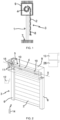
- a home automation installation in accordance with the invention and installed in a building comprising an opening 1, window or door, equipped with a screen 2 belonging to a blackout device 3, in particular a motorized roller shutter.
- the occultation device 3 may be a roller shutter, a canvas blind or one with adjustable slats, or even a rolling gate.
- the present invention applies to all types of occultation device.
- the screen 2 of the occulting device 3 is wound on a winding tube 4 driven by a motorized drive device 5.
- the screen 2 is movable between a wound position, in particular high, and an unwound position, in particular low.
- the movable screen 2 of the occultation device 3 is a closing, occultation and/or solar protection screen, rolling up on the winding tube 4 whose internal diameter is substantially greater than the external diameter of an electromechanical actuator 11, so that the electromechanical actuator 11 can be inserted into the winding tube 4, during the assembly of the occultation device 3.
- the motorized drive device 5 comprises the electromechanical actuator 11, in particular of the tubular type, making it possible to rotate the winding tube 4, so as to move, in particular unwind or wind, the screen 2 of the device. occultation 3.
- the obscuring device 3 comprises the winding tube 4 for rolling up the screen 2. In the mounted state, the electromechanical actuator 11 is inserted into the winding tube 4.
- the rolled-up high position corresponds to the support of a final end blade 8, for example L-shaped, of the apron 2 of the roller shutter 3 against an edge of a box 9 of the roller shutter 3 or to the stopping of the final end blade 8 in a programmed high end-of-travel position.
- the unrolled low position corresponds to the support of the final end blade 8 of the apron 2 of the roller shutter 3 against a threshold 7 of the opening 1 or to the stopping of the final end blade 8 in a programmed low end-of-travel position.
- the first slat of the roller shutter 3, opposite the end slat, is connected to the winding tube 4 by means of at least one joint 10, in particular a band-shaped attachment piece.
- the winding tube 4 is arranged inside the box 9 of the roller shutter 3.
- the apron 2 of the roller shutter 3 winds and unwinds around the winding tube 4 and is housed at least partly inside the box 9.
- the trunk 9 is arranged above the opening 1, or in the upper part of the opening 1.
- the motorized drive device 5 is controlled by a control unit.
- the control unit may be, for example, a local control unit 12, where the local control unit 12 may be connected in a wired or wireless connection to a central control unit 13.
- the central control unit 13 controls the local control unit 12, as well as other similar local control units distributed throughout the building.
- the central control unit 13 may be in communication with a remote weather station outside the building, including, in particular, one or more sensors which may be configured to determine, for example, a temperature, a brightness or even a wind speed.
- a remote control 14 which may be a type of local control unit, and provided with a control keyboard, which includes selection elements and display, further allows a user to intervene on the electromechanical actuator 11 and/or the central control unit 13.
- the motorized drive device 5 is preferably configured to execute the commands for unrolling or rolling up the screen 2 of the occulting device 3, which can be issued, in particular, by the remote control 14.
- the motorized drive device 5 including the electromechanical actuator 11, belonging to the home automation installation of the Figures 1 and 2 .
- the electromechanical actuator 11 comprises an electric motor 16.
- the electric motor 16 comprises a rotor and a stator, not shown and positioned coaxially around an axis of rotation X, which is also the axis of rotation of the winding tube 4 in the mounted configuration of the motorized drive device 5.
- Means for controlling the electromechanical actuator 11, allowing the screen 2 of the occulting device 3 to be moved, are constituted by at least one electronic control unit 15.
- This electronic control unit 15 is capable of putting the electric motor 16 of the electromechanical actuator 11 into operation, and, in particular, of allowing the electric motor 16 to be supplied with electrical energy.
- the electronic control unit 15 controls, in particular, the electric motor 16, so as to open or close the screen 2, as described previously.
- the electronic control unit 15 also comprises a communication module 27, in particular for receiving control orders, the control orders being transmitted by an order transmitter, such as the remote control 14 intended to control the electromechanical actuator 11 or one of the local 12 or central 13 control units.
- the communication module 27 of the electronic control unit 15 is of the wireless type.
- the communication module 27 is configured to receive radio control orders.
- the communication module 27 can also allow the reception of control orders transmitted by wired means.
- the central control unit 13, the electronic control unit 15 or the local control unit 12 can also be in communication with a server 28, so as to control the electromechanical actuator 11 according to data made available remotely via a communication network, in particular an internet network which can be connected to the server 28.
- a communication network in particular an internet network which can be connected to the server 28.
- the control means of the electromechanical actuator 11 comprise hardware and/or software resources.
- the hardware means may include at least one microcontroller.
- the electromechanical actuator 11 is supplied with electrical energy by means of an electrical energy storage device 24, as illustrated in figures 4 to 10 .
- the electrical energy storage device 24 can be recharged by at least one photovoltaic cell 25.
- the photovoltaic cell 25 is used to designate one or more photovoltaic cells depending on the configuration of a stand-alone electrical power supply device 26.
- the electromechanical actuator 11 is electrically connected to the electrical energy storage device 24 by means of at least one electrical power supply cable 18, so as to enable the electromechanical actuator 11 to be supplied with electrical energy from the electrical energy storage device 24.
- a casing 17 of the electromechanical actuator 11 is, preferably, of cylindrical shape.
- the housing 17 is made of a metallic material.
- the material of the electromechanical actuator housing is not limiting and may be different. In particular, it may be a plastic material.
- the electromechanical actuator 11 also comprises a reducer 19, a brake 29 and an output shaft 20.
- the reducer 19 comprises at least one reduction stage.
- Said at least one reduction stage may be an epicyclic type gear train.
- the type and number of reduction stages of the reducer are not limiting.
- the brake 29 may be a spring brake, a cam brake or an electromagnetic brake.
- the electromechanical actuator 11 may also include an end-of-travel and/or obstacle detection device, which may be mechanical or electronic.
- the electric motor 16, the brake 29 and the reducer 19 are mounted inside the casing 17 of the electromechanical actuator 11.
- the winding tube 4 is rotated about the axis of rotation X and the casing 17 of the electromechanical actuator 11 supported by means of two pivot connections.
- the first pivot connection is made at a first end of the winding tube 4 by means of a crown 30 inserted around a first end 17a of the casing 17 of the electromechanical actuator 11.
- the crown 30 thus makes it possible to produce a bearing.
- the second pivot connection is carried out at a second end of the winding tube 4, not visible in this figure.
- the electromechanical actuator 11 comprises a torque support 21.
- the torque support 21 projects at the first end 17a of the casing 17 of the electromechanical actuator 11, in particular the end 17a of the casing 17 receiving the crown 30.
- the torque support 21 of the electromechanical actuator 11 thus makes it possible to fix the electromechanical actuator 11 to a frame 23, in particular to a cheek of the trunk 9.
- the torque support 21 of the electromechanical actuator 11 can make it possible to close the first end 17a of the casing 17.
- the torque support 21 of the electromechanical actuator 11 can support the electronic control unit 15.
- the electronic control unit 15 can be supplied with electrical energy by means of the electrical power supply cable 18 electrically connected to the electrical energy storage device 24.
- the electronic control unit 15 is thus arranged, in other words integrated, inside the casing 17 of the electromechanical actuator 11.
- the electronic control unit 15 is arranged outside the casing 17 of the electromechanical actuator 11 and, in particular, mounted on the frame 23 or in the torque support 21.
- the output shaft 20 of the electromechanical actuator 11 is arranged inside the winding tube 4 and at least partly outside the casing 17 of the electromechanical actuator 11.
- One end of the output shaft 20 projects relative to the casing 17 of the electromechanical actuator 11, in particular relative to a second end 17b of the casing 17 opposite the first end 17a.
- the output shaft 20 of the electromechanical actuator 11 is configured to rotate a connecting element 22 connected to the winding tube 4.
- the connecting element 22 is made in the form of a wheel.
- the electric motor 16 and the reduction gear 19 rotate the output shaft 20.
- the output shaft 20 of the electromechanical actuator 11 rotates the winding tube 4 via the connecting element 22.
- the winding tube 4 rotates the screen 2 of the device occultation 3, so as to open or close opening 1.
- the motorized drive device 5 comprises the autonomous electrical energy supply device 26.
- the autonomous electrical energy supply device 26 comprises the electrical energy storage device 24 and, optionally, the photovoltaic cell 25.
- the autonomous electrical power supply device 26 makes it possible to supply electrical power to the electromechanical actuator 11, without itself being electrically connected to the mains network.
- the electromechanical actuator 11 is electrically connected to the electrical energy storage device 24. And, more particularly, the electronic control unit 15 of the electromechanical actuator 11 is electrically connected to the electrical energy storage device 24.
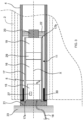
- the electrical energy storage device 24 comprises a housing 31, a battery 32, a first support 33 and a second support 34.
- the battery 32 is disposed inside the housing 31, in an assembled configuration of the electrical energy storage device 24.
- the first support 33 is arranged at a first end 31a of the housing 31, in the assembled configuration of the electrical energy storage device 24.
- the second support 34 is arranged at a second end 31b of the housing 31, in the assembled configuration of the electrical energy storage device 24.
- the second end 31b of the housing 31 is opposite the first end 31a of the housing 31.
- the electrical energy storage device 24 also comprises a first cap 35 and a second cap 36.
- the first cap 35 is assembled with the housing 31 at the first end 31a of the housing 31, in the assembled configuration of the electrical energy storage device 24.
- the second cap 36 is assembled with the housing 31 at the second end 31b of the housing 31, in the assembled configuration of the electrical energy storage device 24.
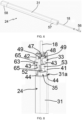
- Each of the first and second supports 33, 34 is assembled with one of the first and second caps 35, 36 by means of elastic snap-fastening elements 37a, 37b, in the assembled configuration of the electrical energy storage device 24.
- the element 38, 6, 9, 39 of the home automation installation may be, in particular, a wall 38 of a building, one of the side slides 6, the box 9 or a fixed frame 39 of a window 40 or a door.
- each of the first and second plugs 35, 36 makes it possible to guarantee a seal at each of the first and second ends 31a, 31b of the housing 31, in particular with respect to the battery 32 arranged inside the housing 31, in the assembled configuration of the electrical energy storage device 24.
- the elastic snap-fastening elements 37a, 37b comprise a tab 37a provided in one of the first and second supports 33, 34 configured to cooperate with a housing 37b provided in one of the first and second plugs 35, 36.
- the tab 37a comprises two flexible arms 37a1, 37a2. Each flexible arm 37a1, 37a2 is configured to cooperate with the housing 37b.
- each of the first and second supports 33, 34 is configured to be fixed to a wall of the element 38, 6, 9, 39 of the home automation installation by means of at least one fixing element, not shown.
- first and second supports 33, 34 are configured to be held in position on the wall of the element 38, 6, 9, 39 of the home automation installation, while allowing the mounting and dismounting of the housing 31 and the battery 32 relative to the first and second supports 33, 34 by means of the elastic snap-fastening fixing elements 37a, 37b.
- the battery 32 can be easily replaced or recharged during maintenance or repair of the electrical energy storage device 24.
- the fixing element of each of the first and second supports 33, 34 on the wall of element 38, 6, 9, 39 of the home automation installation can be, for example, a fixing screw or a rivet.
- the number and type of fixing elements of each of the first and second supports on the wall of the element of the home automation installation are not limiting.
- each of the first and second supports 33, 34 is produced in the form of a bracket.
- the first and second supports 33, 34 make it possible to guarantee installation of the electrical energy storage device 24 in any type of home automation installation for closing or solar protection and in any configuration thereof, in particular on the wall 38 or in a corner of the wall 38 of a building, along one of the lateral slides 6, on a wall or in a corner of the box 9, more particularly inside or outside a wall of the box 9, or on the fixed frame 39 of the window 40 or of a door, as well as horizontally or vertically.
- each of the first and second supports 33, 34 comprises a first wall 41 and a second wall 42.
- the first wall 41 is perpendicular to the second wall 42, so as to form the bracket.
- Each of the first and second walls 41, 42 of each of the first and second supports 33, 34 is configured to cooperate with the wall of the element 38, 6, 9, 39 of the home automation installation.
- each of the first and second walls 41, 42 of each of the first and second supports 33, 34 comprises at least one passage hole 43.
- the passage hole 43 of each of the first and second walls 41, 42 is configured to cooperate with the fixing element of one of the first and second supports 33, 34 with the wall of the element 38, 6, 9, 39 of the home automation installation.
- the assembly of the housing 31, equipped with the battery 32 and the first and second plugs 35, 36, relative to the first and second supports 33, 34 is implemented following the fixing of the first and second supports 33, 34 on the wall of the element 38, 6, 9, 39 of the home automation installation.
- the battery 32 comprises at least one electrical energy storage element, not shown.
- the battery 32 comprises a plurality of electrical energy storage elements.
- the electrical energy storage elements are electrically connected in series.
- the number of electrical energy storage elements in the battery is not limited.
- the 32 battery is waterproof.
- such a battery 32 makes it possible to guarantee the installation of the electrical energy storage device 24 in a simple and reliable manner outside a building or the trunk 9.
- the housing 31 of the electrical energy storage device 24 is produced in the form of a profile.
- the housing 31 of the electrical energy storage device 24 is made of aluminum.
- the material of the housing of the electrical energy storage device is not limiting and may be different. It may be, in particular, a plastic material.
- each of the first and second supports 33, 34 is arranged in the extension of the housing 31 of the electrical energy storage device 24.
- the size of the electrical energy storage device 24 is limited.
- each of the first and second plugs 35, 36 is made of a plastic material.
- each of the first and second plugs 35, 36 is fixed to the housing 31 by means of at least one fixing element 44, in particular two in the exemplary embodiment illustrated in figures 7 to 10 .
- Each fixing element 44 of each of the first and second plugs 35, 36 on the housing 31 may be, for example, a fixing screw.
- each of the first and second caps on the housing are not limiting. They may include, in particular, elastic snap-fastening elements.
- each of the first and second plugs 35, 36 comprises a through hole 45 configured to cooperate with each fixing element 44.
- the housing 31 comprises, at its first end 31a and its second end 31b, a fixing hole 46 configured to cooperate with each fixing element 44.
- first and second supports 33, 34 are symmetrical relative to the housing 31, in the assembled configuration of the electrical energy storage device 24, and are, more particularly, identical.
- each of the first and second supports 33, 34 can be mounted, reversibly, at the first end 31a or the second end 31b of the housing 31, in particular depending on a mounting position of the electromechanical actuator 11 at a first end or at a second end of the winding tube 4.
- first and second symmetrical supports 33, 34 make it possible to simplify the installation of the electrical energy storage device 24 in relation to the home automation installation.
- the electrical energy storage device 24 also comprises the electrical power supply cable 18.
- the first support 33 or the second support 34 or each of the first and second supports 33, 34 comprises a cable clamp 47.
- the cable clamp 47 is configured to cooperate with the electrical power supply cable 18.
- the electrical power cable 18 is held in position by means of the first support 33 or the second support 34 relative to the electrical energy storage device 24, in an assembled configuration of the motorized drive device 5.
- the electrical power supply cable 18 can be held in position relative to one of the first and second supports 33, 34 by means of the cable clamp 47, as well as relative to the wall of the element 38, 6, 9, 39 of the home automation installation, while allowing the disassembly of the housing 31 and the battery 32 relative to the first and second supports 33, 34 by means of the elastic snap-fastening elements 37a, 37b.
- the battery 32 can be easily replaced or recharged during maintenance or repair of the electrical energy storage device 24.
- first support 33 or the second support 34 or each of the first and second supports 33, 34 comprises a passage opening 61 configured to cooperate with the electrical power supply cable 18.
- the cable clamp 47 comprises a tab 48, a first fixing screw 49 and a second fixing screw 49.
- the tab 48 of the cable clamp 47 comprises a first passage opening 50a and a second passage opening 50b.
- Each of the first and second fixing screws 49 is configured to cooperate, on the one hand, with one of the first and second passage openings 50a, 50b provided in the tab 48 of the cable clamp 47 and, on the other hand, with a fixing hole 51 provided in one of the first and second supports 33, 34.
- the first passage opening 50a of the tab 48 of the cable clamp 47 is designed as a hole, in particular an oblong hole. Furthermore, the second passage opening 50b of the tab 48 of the cable clamp 47 is designed as a hook.
- the tab 48 of the cable clamp 47 can be moved in rotation around one of the first and second fixing screws 49 by means of the first and second passage openings 50a, 50b of the tab 48.
- the power supply cable 18 can be inserted inside the cable clamp 47 or removed from the cable clamp 47, while avoiding completely unscrewing the first and second fixing screws 49 of the cable clamp 47 relative to one of the first and second supports 33, 34.
- At least one of the first and second plugs 35, 36 comprises an electrical connector 52 configured to cooperate with a first electrical connector 53 of the electrical power supply cable 18.
- the first electrical connector 53 of the electrical power supply cable 18 can be disconnected from the electrical connector 52 of one of the first and second plugs 35, 36, during a maintenance or repair operation on the electrical energy storage device 24, in particular for replacing or recharging the battery 32.
- disconnecting the first electrical connector 53 of the power supply cable 18 from the electrical connector 52 of one of the first and second caps 35, 36 allows the housing 31 and the battery 32 to be removed from the first and second supports 33, 34, while maintaining the power supply cable 18 in position relative to one of the first and second supports 33, 34 by means of the cable clamp 47.
- the power supply cable 18 can be disconnected and connected from one of the first and second plugs 35, 36, during a configuration operation of the motorized drive device 5.
- the electrical connector 52 of one of the first and second plugs 35, 36 is electrically connected to the battery 32, in particular by means of an electrical cable 54.
- the electrical connector 52 is arranged at least partly inside a housing 55 of one of the first and second plugs 35, 36.
- first stopper 35 or the second stopper 36 or each first and second plugs 35, 36 comprise an electrical connector 52.
- the first electrical connector 53 of the electrical power supply cable 18 is electrically connected to the electrical connector 52 of one of the first and second plugs 35, 36, following the passage of the electrical power supply cable 18 inside the cable clamp 47 of the first support 33 or of the second support 34.
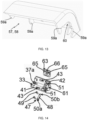
- the electrical energy storage device 24 also comprises a first cover 57 and a second cover 58.
- Each of the first and second covers 57, 58 is configured to cooperate with one of the first and second supports 33, 34.
- first cover 57 is disposed at the first end 31a of the housing 31, in the assembled configuration of the electrical energy storage device 24.
- the second cover 58 is disposed at the second end 31b of the housing 31, in the assembled configuration of the electrical energy storage device 24.
- each of the first and second covers 57, 58 makes it possible to mask one of the first and second supports 33, 34, so as to improve the aesthetic appearance of the electrical energy storage device 24 and to protect the battery 32, as well as the electrical connection of the latter with the electrical power supply cable 18.
- first and second covers 57, 58 make it possible to prevent involuntary removal of the housing 31 and the battery 32 relative to the first and second supports 33, 34, in particular by the disengagement of the elastic snap-fastening elements 37a, 37b connecting each of the first and second caps 35, 36 to one of the first and second supports 33, 34.
- each of the first and second covers 57, 58 is removable relative to one of the first and second supports 33, 34.
- each of the first and second covers 57, 58 is assembled with one of the first and second supports 33, 34 by means of elastic snap-fastening elements 59a, 59b.
- the elastic snap-fastening elements 59a, 59b are provided respectively on the first or second cover 57, 58 and on the first or second support 33, 34.
- each of the first and second plugs 35, 36 is configured to cooperate with one of the first and second covers 57, 58, in particular to be covered by one of the first and second covers 57, 58 and to be housed inside one of the first and second covers 57, 58.
- first cover 57 or the second cover 58 or each of the first and second covers 57, 58 comprises a passage opening 60 configured to cooperate with the electrical power supply cable 18.
- the electrical energy storage device 24 also comprises a closing element 62 configured to cooperate with the passage opening 60 of one of the first and second covers 57, 58, in particular the second cover 58 positioned on the side opposite the electrical power supply cable 18, in other words the second cover 58 not cooperating with the electrical power supply cable 18, in the assembled configuration of the electrical energy storage device 24.
- the electrical energy storage device 24 also comprises a first wedge 63 and a second wedge 64.
- Each of the first and second wedges 63, 64 is configured to cooperate with one of the first and second supports 33, 34.
- the first and second shims 63, 64 make it possible to offset the electrical energy storage device 24 and, more particularly, the housing 31 relative to the wall of the element 38, 6, 9, 39 of the home automation installation, in particular in the case where the wall of the element 38, 6, 9, 39 of the home automation installation has imperfections or roughness.
- each of the first and second wedges 63, 64 is configured to be fixed to one of the first and second supports 33, 34 by means of fixing elements 65.
- the fixing elements 65 of each of the first and second wedges 63, 64 on one of the first and second supports 33, 34 may be, for example, elastic snap-fastening fixing elements, in particular two in number.
- each fastening element 65 is configured to cooperate and, more particularly, to engage in the passage hole 43 of one of the first and second walls 41, 42 of one of the first and second supports 33, 34.
- the number and type of fixing elements of each of the first and second wedges on one of the first and second supports are not limiting.
- each of the first and second wedges 63, 64 comprises at least one passage opening 66 of at least one fixing element of each of the first and second supports 33, 34 on the wall of the element 38, 6, 9, 39 of the home automation installation.
- the electrical energy storage device 24 is of the rechargeable type and is configured to supply electrical energy to the electromechanical actuator 11. Furthermore, the electrical energy storage device 24 is configured to be supplied with electrical energy by the photovoltaic cell 25.
- the recharging of the electrical energy storage device 24 is implemented by solar energy by means of the photovoltaic cell 25.
- the electrical energy storage device 24 can be recharged without having to dismantle a part of the box 9 of the concealment device 3.
- the motorized drive device 5 and, in particular, the photovoltaic cell 25 comprises charging elements configured to charge the battery 32 of the electrical energy storage device 24 from the solar energy recovered by the photovoltaic cell 25.
- the charging elements configured to charge the battery 32 of the electrical energy storage device 24 from solar energy make it possible to convert the solar energy recovered by the photovoltaic cell 25 into electrical energy.
- the autonomous electrical power supply device 26 comprises a plurality of photovoltaic cells 25 constituting a photovoltaic panel.
- the electrical energy supply to the electromechanical actuator 11 by the electrical energy storage device 24 is configured to replace an electrical energy supply to the electromechanical actuator 11 by an electrical energy supply network.
- the supply of electrical energy to the electromechanical actuator 11 by the electrical energy storage device 24 makes it possible to dispense with a connection to the electrical energy supply network.
- the electrical energy supply to the electromechanical actuator 11 is implemented, on the one hand, by the electrical energy storage device 24 and, on the other hand, by an electrical energy supply network.
- the electromechanical actuator 11 is then supplied with electrical energy either by the electrical energy storage device 24 or by the electrical energy supply network.
- the supply of electrical energy to the electromechanical actuator 11 by the electrical energy storage device 24 can make it possible, in particular, to compensate for a cut in the electrical energy supply to the electromechanical actuator 11 by an electrical energy supply network.
- the supply of electrical energy to the electromechanical actuator 11 by the electrical energy supply network makes it possible to recharge the electrical energy storage device 24, in particular when the electrical energy storage device 24 is insufficiently recharged by the photovoltaic cell 25.
- the photovoltaic cell 25 is electrically connected to the electrical energy storage device 24 directly or via the electromechanical actuator 11.
- such an elastic snap-fastening assembly allows simple, rapid and intuitive assembly and disassembly of the electrical energy storage device and, more particularly, of the housing and the battery relative to the first and second supports, so as to be able to replace or recharge the battery, without requiring the use of specific tools and without causing damage to the home automation installation.
Landscapes
- Engineering & Computer Science (AREA)
- Structural Engineering (AREA)
- Architecture (AREA)
- Civil Engineering (AREA)
- Chemical & Material Sciences (AREA)
- Chemical Kinetics & Catalysis (AREA)
- Electrochemistry (AREA)
- General Chemical & Material Sciences (AREA)
- Charge And Discharge Circuits For Batteries Or The Like (AREA)
- Battery Mounting, Suspending (AREA)
- Motor Or Generator Frames (AREA)
Claims (11)
- Speichervorrichtung für elektrische Energie (24) für eine Haustechnikanlage zum Schließen oder Sonnenschutz, die Speichervorrichtung für elektrische Energie (24) mindestens umfassend:- ein Gehäuse (31),- eine Batterie (32), wobei die Batterie (32) in einer zusammengebauten Konfiguration der Speichervorrichtung für elektrische Energie (24) im Inneren des Gehäuses (31) angeordnet ist,- eine erste Halterung (33), wobei die erste Halterung (33) in der zusammengebauten Konfiguration der Speichervorrichtung für elektrische Energie (24) an einem ersten Ende (31a) des Gehäuses (31) angeordnet ist,- eine erste Kappe (35) und eine zweite Kappe (36), wobei die erste Kappe (35) in der zusammengebauten Konfiguration der Speichervorrichtung für elektrische Energie (24) an dem ersten Ende (31a) des Gehäuses (31) mit dem Gehäuse (31) zusammengebaut ist, wobei die zweite Kappe (36) in der zusammengebauten Konfiguration der Speichervorrichtung für elektrische Energie (24) an dem zweiten Ende (31b) des Gehäuses (31) mit dem Gehäuse (31) zusammengebaut ist,dadurch gekennzeichnet, dass die Speichervorrichtung für elektrische Energie (24) auch eine zweite Halterung (34) umfasst, wobei die zweite Halterung (34) in der zusammengebauten Konfiguration der Speichervorrichtung für elektrische Energie (24) an einem zweiten Ende (31b) des Gehäuses (31) angeordnet ist, wobei das zweite Ende (31b) des Gehäuses (31) gegenüber dem ersten Ende (31a) des Gehäuses (31) ist,und dass jede von der ersten und der zweiten Halterung (33, 34) in der zusammengebauten Konfiguration der Speichervorrichtung für elektrische Energie (24) mittels elastischer Rastbefestigungselemente (37a, 37b) mit einer von der ersten und der zweiten Kappe (35, 36) zusammengebaut ist.
- Speichervorrichtung für elektrische Energie (24) für eine Haustechnikanlage zum Schließen oder Sonnenschutz nach Anspruch 1, dadurch gekennzeichnet, dass die elastischen Rastbefestigungselemente (37a, 37b) eine in einer der ersten und zweiten Halterungen (33, 34) ausgebildete Zunge (37a) umfassen, die konfiguriert ist, um mit einer in einer der ersten und zweiten Kappen (35, 36) gebildeten Aufnahme (37b) zusammenzuwirken.
- Speichervorrichtung für elektrische Energie (24) für eine Haustechnikanlage zum Schließen oder Sonnenschutz nach Anspruch 1 oder nach Anspruch 2, dadurch gekennzeichnet, dass jede von der ersten und der zweiten Halterung (33, 34) in Form eines Winkels ausgeführt ist.
- Speichervorrichtung für elektrische Energie (24) für eine Haustechnikanlage zum Schließen oder Sonnenschutz nach einem der Ansprüche 1 bis 3, dadurch gekennzeichnet, dass die erste und die zweite Halterung (33, 34) in der zusammengebauten Konfiguration der Speichervorrichtung für elektrische Energie (24) symmetrisch zu dem Gehäuse (31) sind.
- Speichervorrichtung für elektrische Energie (24) für eine Haustechnikanlage zum Schließen oder Sonnenschutz nach einem der Ansprüche 1 bis 4, dadurch gekennzeichnet, dass die Speichervorrichtung für elektrische Energie (24) auch ein Stromversorgungskabel (18) umfasst und dass mindestens eine von der ersten und der zweiten Kappe (35, 36) einen elektrischen Verbinder (52) umfasst, der konfiguriert ist, um mit einem ersten elektrischen Verbinder (53) des Stromversorgungskabels (18) zusammenzuwirken.
- Speichervorrichtung für elektrische Energie (24) für eine Haustechnikanlage zum Schließen oder Sonnenschutz nach Anspruch 5, dadurch gekennzeichnet, dass die erste Halterung (33) oder die zweite Halterung (34) oder jede von der ersten und der zweiten Halterung (33, 34) eine Kabelklemme (47) umfasst, und dass die Kabelklemme (47) konfiguriert ist, um mit dem Stromversorgungskabel (18) zusammenzuwirken.
- Speichervorrichtung für elektrische Energie (24) für eine Haustechnikanlage zum Schließen oder Sonnenschutz nach einem der Ansprüche 1 bis 6, dadurch gekennzeichnet, dass die Speichervorrichtung für elektrische Energie (24) auch eine erste Abdeckung (57) und eine zweite Abdeckung (58) umfasst, und dass jede von der ersten und der zweiten Abdeckung (57, 58) konfiguriert ist, um mit einer von der ersten und der zweiten Halterung (33, 34) zusammenzuwirken, wobei die erste Abdeckung (57) in der zusammengebauten Konfiguration der Speichervorrichtung für elektrische Energie (24) an dem ersten Ende (31a) des Gehäuses (31) angeordnet ist, und die zweite Abdeckung (58) in der zusammengebauten Konfiguration der Speichervorrichtung für elektrische Energie (24) an dem zweiten Ende (31b) des Gehäuses (31) angeordnet ist.
- Speichervorrichtung für elektrische Energie (24) für eine Haustechnikanlage zum Schließen oder Sonnenschutz nach einem der Ansprüche 1 bis 7, dadurch gekennzeichnet, dass jede von der ersten und der zweiten Halterung (33, 34) konfiguriert ist, um mittels mindestens eines Befestigungselements an einer Wand eines Elements (38, 6, 9, 39) der Haustechnikanlage befestigt zu werden.
- Motorisierte Antriebsvorrichtung (5) für eine Haustechnikanlage zum Schließen oder Sonnenschutz, mindestens umfassend:- einen elektromechanischen Aktuator (11),- eine autonome Speichervorrichtung für elektrische Energie (26), wobei die autonome Speichervorrichtung für elektrische Energie (26) mindestens eine Speichervorrichtung für elektrische Energie (24) nach einem der Ansprüche 1 bis 8 umfasst, wobei der elektromechanische Aktuator (11) elektrisch mit der Speichervorrichtung für elektrische Energie (24) verbunden ist.
- Haustechnikanlage zum Schließen oder Sonnenschutz, umfassend einen Schirm (2), der mittels einer motorisierten Antriebsvorrichtung (5) auf ein Wickelrohr (4) aufrollbar ist, das von einem elektromechanischen Aktuator (11) in Drehung versetzt wird, dadurch gekennzeichnet, dass die motorisierte Antriebsvorrichtung (5) dem Anspruch 9 entspricht.
- Haustechnikanlage zum Schließen oder Sonnenschutz nach Anspruch 10, dadurch gekennzeichnet, dass die Wand des Elements (38, 6, 9, 39) der Haustechnikanlage eine Wand (38) eines Gebäudes, eine Seitenführung (6) einer Abdeckvorrichtung (3), ein Kasten (9) einer Abdeckvorrichtung (3) oder ein Blendrahmen (39) eines Fensters (40) oder einer Tür ist.
Applications Claiming Priority (1)
| Application Number | Priority Date | Filing Date | Title |
|---|---|---|---|
| FR1851236A FR3077840B1 (fr) | 2018-02-14 | 2018-02-14 | Dispositif de stockage d'energie electrique, dispositif d'entrainement motorise et installation domotique associes |
Publications (2)
| Publication Number | Publication Date |
|---|---|
| EP3528310A1 EP3528310A1 (de) | 2019-08-21 |
| EP3528310B1 true EP3528310B1 (de) | 2025-06-11 |
Family
ID=62683303
Family Applications (1)
| Application Number | Title | Priority Date | Filing Date |
|---|---|---|---|
| EP19156974.8A Active EP3528310B1 (de) | 2018-02-14 | 2019-02-13 | Speichervorrichtung für elektrische energie, entsprechende motorisierte antriebsvorrichtung und entsprechende haustechnikanlage |
Country Status (3)
| Country | Link |
|---|---|
| EP (1) | EP3528310B1 (de) |
| FR (1) | FR3077840B1 (de) |
| PL (1) | PL3528310T3 (de) |
Families Citing this family (5)
| Publication number | Priority date | Publication date | Assignee | Title |
|---|---|---|---|---|
| CN118088021A (zh) * | 2021-04-19 | 2024-05-28 | 德侑股份有限公司 | 支撑结构及含有支撑结构的电动窗帘 |
| FR3135295B1 (fr) * | 2022-05-03 | 2025-01-17 | Somfy Activites Sa | Accessoire de câblage électrique à un réseau d’alimentation électrique d’un actionneur électromécanique pour un dispositif d’occultation et dispositif d’occultation associé |
| FR3145371B1 (fr) | 2023-02-01 | 2025-01-31 | Soprofen | Coffre pour volet roulant ou similaire en motorisation autonome |
| FR3147315A1 (fr) * | 2023-03-28 | 2024-10-04 | Simu | Dispositif d’occultation |
| FR3147314B1 (fr) * | 2023-03-28 | 2025-04-04 | Simu | Dispositif d’occultation |
Citations (3)
| Publication number | Priority date | Publication date | Assignee | Title |
|---|---|---|---|---|
| US6446693B1 (en) * | 1999-01-11 | 2002-09-10 | Hunter Douglas Inc. | Headrail and control system for powered coverings for architectural openings |
| US20100092855A1 (en) * | 2008-10-14 | 2010-04-15 | Li-Ming Cheng | Battery Pack Apparatus For Electric Window Coverings |
| US20160374497A1 (en) * | 2013-07-10 | 2016-12-29 | Qmotion Incorporated | Battery Retaining System and Method for Motorized Architectural Coverings |
Family Cites Families (5)
| Publication number | Priority date | Publication date | Assignee | Title |
|---|---|---|---|---|
| US8371358B1 (en) * | 2008-12-04 | 2013-02-12 | Homerun Holdings Corp | Removable battery system and method |
| WO2014144008A2 (en) * | 2013-03-15 | 2014-09-18 | Springs Window Fashions, Llc | Window covering motorized lift and control operating system |
| US20140352897A1 (en) * | 2013-05-28 | 2014-12-04 | Qmotion Incorporated | Bottom Load Bracket For An Architectural Covering |
| FR3020395A1 (fr) * | 2014-04-25 | 2015-10-30 | Simu | Dispositif de fixation d'un mecanisme d'entrainement motorise d'un tube d'enroulement d'un ecran dans un coffre et installation domotique comprenant un tel dispositif |
| US10094169B2 (en) * | 2014-11-01 | 2018-10-09 | Lutron Electronics Co., Inc. | Interlocking pivotable fascia for motorized window treatment |
-
2018
- 2018-02-14 FR FR1851236A patent/FR3077840B1/fr active Active
-
2019
- 2019-02-13 PL PL19156974.8T patent/PL3528310T3/pl unknown
- 2019-02-13 EP EP19156974.8A patent/EP3528310B1/de active Active
Patent Citations (3)
| Publication number | Priority date | Publication date | Assignee | Title |
|---|---|---|---|---|
| US6446693B1 (en) * | 1999-01-11 | 2002-09-10 | Hunter Douglas Inc. | Headrail and control system for powered coverings for architectural openings |
| US20100092855A1 (en) * | 2008-10-14 | 2010-04-15 | Li-Ming Cheng | Battery Pack Apparatus For Electric Window Coverings |
| US20160374497A1 (en) * | 2013-07-10 | 2016-12-29 | Qmotion Incorporated | Battery Retaining System and Method for Motorized Architectural Coverings |
Also Published As
| Publication number | Publication date |
|---|---|
| EP3528310A1 (de) | 2019-08-21 |
| PL3528310T3 (pl) | 2025-08-11 |
| FR3077840B1 (fr) | 2020-03-13 |
| FR3077840A1 (fr) | 2019-08-16 |
Similar Documents
| Publication | Publication Date | Title |
|---|---|---|
| EP3528310B1 (de) | Speichervorrichtung für elektrische energie, entsprechende motorisierte antriebsvorrichtung und entsprechende haustechnikanlage | |
| EP3717728B1 (de) | Elektromechanischer aktuator und heimautomatisierungsanlage mit einem solchen aktuator | |
| EP3803021B1 (de) | Rollladenvorrichtung für eine heimautomatisierungs- oder sonnenschutzvorrichtung in einem gebäude und zugehörige heimautomatisierungsinstallation | |
| EP2957705A1 (de) | Elektromechanisches stellglied und heiminstallation, die ein solches stellglied umfasst | |
| EP3695086B1 (de) | Rohrmotor, heimautomatisierung mit diesem motor und sein herstellungsverfahren | |
| EP3695087B1 (de) | Rohrförmiger elektromechanischer aktuator, heimautomatisierungsausrüstung mit solch einem aktuator und verfahren zur verbindung solch eines aktuators | |
| WO2016166206A1 (fr) | Dispositif d'entraînement motorisé pour une installation domotique de fermeture ou de protection solaire, installation domotique associée et procédé de commande en fonctionnement d'un tel dispositif | |
| EP3695089A1 (de) | Rohrförmiger elektromechanischer aktuator und einen solchen aktuator enthaltende heimautomatisierungsanlage | |
| EP3870796B1 (de) | Elektromechanischer aktuator und heimautomatisierungsanlage mit einem solchen aktuator | |
| EP3588772A1 (de) | Autonome stromzuführungsvorrichtung, entsprechende motorisierte antriebsvorrichtung und entsprechende haustechnikanlage | |
| FR3096194A1 (fr) | Actionneur électromécanique et installation de fermeture, d’occultation ou de protection solaire comprenant un tel actionneur électromécanique | |
| FR3100266A1 (fr) | Dispositif d’alimentation en énergie électrique autonome, dispositif d’entraînement motorisé, installation et fenêtre associés | |
| EP2937505B1 (de) | Heimanlage, die eine befestigungsvorrichtung für einen motorisierten antriebsmechanismus eines aufrollrohrs eines bildschirms in einem kasten umfasst | |
| FR3123678A1 (fr) | Actionneur électromécanique d’un dispositif d’occultation, dispositif d’occultation associé et procédé d’assemblage d’un tel actionneur | |
| EP4442954B1 (de) | Verdunkelungsvorrichtung | |
| EP4086423B1 (de) | Motorisierte antriebsvorrichtung für eine verdunkelungsvorrichtung und entsprechende verdunkelungsvorrichtung | |
| EP3135852B1 (de) | Endkappe mit kabelführung für den rohrmotor einer wickelwelle | |
| EP4576463A1 (de) | Stromversorgungsvorrichtung, motorisierte antriebsvorrichtung mit solch einer stromversorgungsvorrichtung und verdunkelungsvorrichtung dafür | |
| EP4704313A1 (de) | Elektromechanischer aktuator und verdunkelungsvorrichtung mit solch einem elektromechanischen aktuator | |
| EP4704501A1 (de) | Stromversorgungsvorrichtung, motorantriebsvorrichtung mit einer solchen stromversorgungsvorrichtung und verdunkelungsvorrichtung dafür | |
| FR3139592A1 (fr) | Dispositif d’entraînement motorisé d’un dispositif d’occultation et dispositif d’occultation associé |
Legal Events
| Date | Code | Title | Description |
|---|---|---|---|
| PUAI | Public reference made under article 153(3) epc to a published international application that has entered the european phase |
Free format text: ORIGINAL CODE: 0009012 |
|
| STAA | Information on the status of an ep patent application or granted ep patent |
Free format text: STATUS: THE APPLICATION HAS BEEN PUBLISHED |
|
| AK | Designated contracting states |
Kind code of ref document: A1 Designated state(s): AL AT BE BG CH CY CZ DE DK EE ES FI FR GB GR HR HU IE IS IT LI LT LU LV MC MK MT NL NO PL PT RO RS SE SI SK SM TR |
|
| AX | Request for extension of the european patent |
Extension state: BA ME |
|
| STAA | Information on the status of an ep patent application or granted ep patent |
Free format text: STATUS: REQUEST FOR EXAMINATION WAS MADE |
|
| 17P | Request for examination filed |
Effective date: 20200210 |
|
| RBV | Designated contracting states (corrected) |
Designated state(s): AL AT BE BG CH CY CZ DE DK EE ES FI FR GB GR HR HU IE IS IT LI LT LU LV MC MK MT NL NO PL PT RO RS SE SI SK SM TR |
|
| RAP1 | Party data changed (applicant data changed or rights of an application transferred) |
Owner name: SIMU |
|
| STAA | Information on the status of an ep patent application or granted ep patent |
Free format text: STATUS: EXAMINATION IS IN PROGRESS |
|
| 17Q | First examination report despatched |
Effective date: 20220704 |
|
| REG | Reference to a national code |
Ref country code: DE Ref legal event code: R079 Free format text: PREVIOUS MAIN CLASS: H01M0002100000 Ipc: E06B0009170000 Ref country code: DE Ref legal event code: R079 Ref document number: 602019070968 Country of ref document: DE Free format text: PREVIOUS MAIN CLASS: H01M0002100000 Ipc: E06B0009170000 |
|
| GRAP | Despatch of communication of intention to grant a patent |
Free format text: ORIGINAL CODE: EPIDOSNIGR1 |
|
| STAA | Information on the status of an ep patent application or granted ep patent |
Free format text: STATUS: GRANT OF PATENT IS INTENDED |
|
| RIC1 | Information provided on ipc code assigned before grant |
Ipc: E06B 9/174 20060101ALI20250210BHEP Ipc: H01M 50/213 20210101ALI20250210BHEP Ipc: E06B 9/24 20060101ALI20250210BHEP Ipc: E06B 9/72 20060101ALI20250210BHEP Ipc: E06B 9/50 20060101ALI20250210BHEP Ipc: E06B 9/42 20060101ALI20250210BHEP Ipc: E06B 9/17 20060101AFI20250210BHEP |
|
| INTG | Intention to grant announced |
Effective date: 20250311 |
|
| GRAS | Grant fee paid |
Free format text: ORIGINAL CODE: EPIDOSNIGR3 |
|
| GRAA | (expected) grant |
Free format text: ORIGINAL CODE: 0009210 |
|
| STAA | Information on the status of an ep patent application or granted ep patent |
Free format text: STATUS: THE PATENT HAS BEEN GRANTED |
|
| AK | Designated contracting states |
Kind code of ref document: B1 Designated state(s): AL AT BE BG CH CY CZ DE DK EE ES FI FR GB GR HR HU IE IS IT LI LT LU LV MC MK MT NL NO PL PT RO RS SE SI SK SM TR |
|
| REG | Reference to a national code |
Ref country code: GB Ref legal event code: FG4D Free format text: NOT ENGLISH |
|
| REG | Reference to a national code |
Ref country code: CH Ref legal event code: EP |
|
| REG | Reference to a national code |
Ref country code: IE Ref legal event code: FG4D Free format text: LANGUAGE OF EP DOCUMENT: FRENCH |
|
| REG | Reference to a national code |
Ref country code: DE Ref legal event code: R096 Ref document number: 602019070968 Country of ref document: DE |
|
| REG | Reference to a national code |
Ref country code: NL Ref legal event code: FP |
|
| PG25 | Lapsed in a contracting state [announced via postgrant information from national office to epo] |
Ref country code: FI Free format text: LAPSE BECAUSE OF FAILURE TO SUBMIT A TRANSLATION OF THE DESCRIPTION OR TO PAY THE FEE WITHIN THE PRESCRIBED TIME-LIMIT Effective date: 20250611 Ref country code: ES Free format text: LAPSE BECAUSE OF FAILURE TO SUBMIT A TRANSLATION OF THE DESCRIPTION OR TO PAY THE FEE WITHIN THE PRESCRIBED TIME-LIMIT Effective date: 20250611 |
|
| REG | Reference to a national code |
Ref country code: LT Ref legal event code: MG9D |
|
| PG25 | Lapsed in a contracting state [announced via postgrant information from national office to epo] |
Ref country code: NO Free format text: LAPSE BECAUSE OF FAILURE TO SUBMIT A TRANSLATION OF THE DESCRIPTION OR TO PAY THE FEE WITHIN THE PRESCRIBED TIME-LIMIT Effective date: 20250911 Ref country code: GR Free format text: LAPSE BECAUSE OF FAILURE TO SUBMIT A TRANSLATION OF THE DESCRIPTION OR TO PAY THE FEE WITHIN THE PRESCRIBED TIME-LIMIT Effective date: 20250912 |
|
| PG25 | Lapsed in a contracting state [announced via postgrant information from national office to epo] |
Ref country code: BG Free format text: LAPSE BECAUSE OF FAILURE TO SUBMIT A TRANSLATION OF THE DESCRIPTION OR TO PAY THE FEE WITHIN THE PRESCRIBED TIME-LIMIT Effective date: 20250611 |
|
| PG25 | Lapsed in a contracting state [announced via postgrant information from national office to epo] |
Ref country code: HR Free format text: LAPSE BECAUSE OF FAILURE TO SUBMIT A TRANSLATION OF THE DESCRIPTION OR TO PAY THE FEE WITHIN THE PRESCRIBED TIME-LIMIT Effective date: 20250611 |
|
| PG25 | Lapsed in a contracting state [announced via postgrant information from national office to epo] |
Ref country code: RS Free format text: LAPSE BECAUSE OF FAILURE TO SUBMIT A TRANSLATION OF THE DESCRIPTION OR TO PAY THE FEE WITHIN THE PRESCRIBED TIME-LIMIT Effective date: 20250911 |
|
| PG25 | Lapsed in a contracting state [announced via postgrant information from national office to epo] |
Ref country code: LV Free format text: LAPSE BECAUSE OF FAILURE TO SUBMIT A TRANSLATION OF THE DESCRIPTION OR TO PAY THE FEE WITHIN THE PRESCRIBED TIME-LIMIT Effective date: 20250611 |
|
| PG25 | Lapsed in a contracting state [announced via postgrant information from national office to epo] |
Ref country code: PT Free format text: LAPSE BECAUSE OF FAILURE TO SUBMIT A TRANSLATION OF THE DESCRIPTION OR TO PAY THE FEE WITHIN THE PRESCRIBED TIME-LIMIT Effective date: 20251013 |
|
| REG | Reference to a national code |
Ref country code: AT Ref legal event code: MK05 Ref document number: 1802406 Country of ref document: AT Kind code of ref document: T Effective date: 20250611 |
|
| PG25 | Lapsed in a contracting state [announced via postgrant information from national office to epo] |
Ref country code: IS Free format text: LAPSE BECAUSE OF FAILURE TO SUBMIT A TRANSLATION OF THE DESCRIPTION OR TO PAY THE FEE WITHIN THE PRESCRIBED TIME-LIMIT Effective date: 20251011 |
|
| PG25 | Lapsed in a contracting state [announced via postgrant information from national office to epo] |
Ref country code: SM Free format text: LAPSE BECAUSE OF FAILURE TO SUBMIT A TRANSLATION OF THE DESCRIPTION OR TO PAY THE FEE WITHIN THE PRESCRIBED TIME-LIMIT Effective date: 20250611 Ref country code: AT Free format text: LAPSE BECAUSE OF FAILURE TO SUBMIT A TRANSLATION OF THE DESCRIPTION OR TO PAY THE FEE WITHIN THE PRESCRIBED TIME-LIMIT Effective date: 20250611 |
|
| PG25 | Lapsed in a contracting state [announced via postgrant information from national office to epo] |
Ref country code: CZ Free format text: LAPSE BECAUSE OF FAILURE TO SUBMIT A TRANSLATION OF THE DESCRIPTION OR TO PAY THE FEE WITHIN THE PRESCRIBED TIME-LIMIT Effective date: 20250611 |
|
| PG25 | Lapsed in a contracting state [announced via postgrant information from national office to epo] |
Ref country code: EE Free format text: LAPSE BECAUSE OF FAILURE TO SUBMIT A TRANSLATION OF THE DESCRIPTION OR TO PAY THE FEE WITHIN THE PRESCRIBED TIME-LIMIT Effective date: 20250611 |
|
| PG25 | Lapsed in a contracting state [announced via postgrant information from national office to epo] |
Ref country code: SK Free format text: LAPSE BECAUSE OF FAILURE TO SUBMIT A TRANSLATION OF THE DESCRIPTION OR TO PAY THE FEE WITHIN THE PRESCRIBED TIME-LIMIT Effective date: 20250611 Ref country code: RO Free format text: LAPSE BECAUSE OF FAILURE TO SUBMIT A TRANSLATION OF THE DESCRIPTION OR TO PAY THE FEE WITHIN THE PRESCRIBED TIME-LIMIT Effective date: 20250611 |
|
| PGFP | Annual fee paid to national office [announced via postgrant information from national office to epo] |
Ref country code: NL Payment date: 20260127 Year of fee payment: 8 |