EP3528103B1 - Procédé de verrouillage d'écran, terminal et dispositif de verrouillage d'écran - Google Patents
Procédé de verrouillage d'écran, terminal et dispositif de verrouillage d'écran Download PDFInfo
- Publication number
- EP3528103B1 EP3528103B1 EP16919877.7A EP16919877A EP3528103B1 EP 3528103 B1 EP3528103 B1 EP 3528103B1 EP 16919877 A EP16919877 A EP 16919877A EP 3528103 B1 EP3528103 B1 EP 3528103B1
- Authority
- EP
- European Patent Office
- Prior art keywords
- touchscreen
- sliding operation
- terminal
- area
- edge
- Prior art date
- Legal status (The legal status is an assumption and is not a legal conclusion. Google has not performed a legal analysis and makes no representation as to the accuracy of the status listed.)
- Active
Links
- 238000000034 method Methods 0.000 title claims description 114
- 230000008569 process Effects 0.000 claims description 19
- 230000000694 effects Effects 0.000 claims description 15
- 230000000007 visual effect Effects 0.000 claims description 9
- 238000010586 diagram Methods 0.000 description 38
- 230000006870 function Effects 0.000 description 23
- 238000012545 processing Methods 0.000 description 12
- 238000001514 detection method Methods 0.000 description 11
- 238000004891 communication Methods 0.000 description 5
- 238000004590 computer program Methods 0.000 description 5
- 230000004044 response Effects 0.000 description 5
- 230000008859 change Effects 0.000 description 4
- 230000003287 optical effect Effects 0.000 description 4
- 230000001960 triggered effect Effects 0.000 description 4
- 230000009471 action Effects 0.000 description 3
- 238000005516 engineering process Methods 0.000 description 3
- 238000007726 management method Methods 0.000 description 3
- 238000013500 data storage Methods 0.000 description 2
- 230000003993 interaction Effects 0.000 description 2
- 239000004973 liquid crystal related substance Substances 0.000 description 2
- 230000007774 longterm Effects 0.000 description 2
- 238000010295 mobile communication Methods 0.000 description 2
- 238000012986 modification Methods 0.000 description 2
- 230000004048 modification Effects 0.000 description 2
- 230000008447 perception Effects 0.000 description 2
- 238000000926 separation method Methods 0.000 description 2
- 230000005236 sound signal Effects 0.000 description 2
- 230000001133 acceleration Effects 0.000 description 1
- 238000013459 approach Methods 0.000 description 1
- 230000006399 behavior Effects 0.000 description 1
- 238000006243 chemical reaction Methods 0.000 description 1
- 230000003111 delayed effect Effects 0.000 description 1
- 238000012217 deletion Methods 0.000 description 1
- 230000037430 deletion Effects 0.000 description 1
- 230000001419 dependent effect Effects 0.000 description 1
- 238000013461 design Methods 0.000 description 1
- 238000007599 discharging Methods 0.000 description 1
- 230000005484 gravity Effects 0.000 description 1
- 238000012544 monitoring process Methods 0.000 description 1
- 230000003068 static effect Effects 0.000 description 1
- 238000010897 surface acoustic wave method Methods 0.000 description 1
Images


Classifications
-
- H—ELECTRICITY
- H04—ELECTRIC COMMUNICATION TECHNIQUE
- H04M—TELEPHONIC COMMUNICATION
- H04M1/00—Substation equipment, e.g. for use by subscribers
- H04M1/02—Constructional features of telephone sets
- H04M1/0202—Portable telephone sets, e.g. cordless phones, mobile phones or bar type handsets
- H04M1/0279—Improving the user comfort or ergonomics
-
- G—PHYSICS
- G06—COMPUTING; CALCULATING OR COUNTING
- G06F—ELECTRIC DIGITAL DATA PROCESSING
- G06F3/00—Input arrangements for transferring data to be processed into a form capable of being handled by the computer; Output arrangements for transferring data from processing unit to output unit, e.g. interface arrangements
- G06F3/01—Input arrangements or combined input and output arrangements for interaction between user and computer
- G06F3/048—Interaction techniques based on graphical user interfaces [GUI]
- G06F3/0487—Interaction techniques based on graphical user interfaces [GUI] using specific features provided by the input device, e.g. functions controlled by the rotation of a mouse with dual sensing arrangements, or of the nature of the input device, e.g. tap gestures based on pressure sensed by a digitiser
- G06F3/0488—Interaction techniques based on graphical user interfaces [GUI] using specific features provided by the input device, e.g. functions controlled by the rotation of a mouse with dual sensing arrangements, or of the nature of the input device, e.g. tap gestures based on pressure sensed by a digitiser using a touch-screen or digitiser, e.g. input of commands through traced gestures
- G06F3/04883—Interaction techniques based on graphical user interfaces [GUI] using specific features provided by the input device, e.g. functions controlled by the rotation of a mouse with dual sensing arrangements, or of the nature of the input device, e.g. tap gestures based on pressure sensed by a digitiser using a touch-screen or digitiser, e.g. input of commands through traced gestures for inputting data by handwriting, e.g. gesture or text
-
- G—PHYSICS
- G06—COMPUTING; CALCULATING OR COUNTING
- G06F—ELECTRIC DIGITAL DATA PROCESSING
- G06F3/00—Input arrangements for transferring data to be processed into a form capable of being handled by the computer; Output arrangements for transferring data from processing unit to output unit, e.g. interface arrangements
- G06F3/01—Input arrangements or combined input and output arrangements for interaction between user and computer
- G06F3/048—Interaction techniques based on graphical user interfaces [GUI]
- G06F3/0487—Interaction techniques based on graphical user interfaces [GUI] using specific features provided by the input device, e.g. functions controlled by the rotation of a mouse with dual sensing arrangements, or of the nature of the input device, e.g. tap gestures based on pressure sensed by a digitiser
- G06F3/0488—Interaction techniques based on graphical user interfaces [GUI] using specific features provided by the input device, e.g. functions controlled by the rotation of a mouse with dual sensing arrangements, or of the nature of the input device, e.g. tap gestures based on pressure sensed by a digitiser using a touch-screen or digitiser, e.g. input of commands through traced gestures
- G06F3/04886—Interaction techniques based on graphical user interfaces [GUI] using specific features provided by the input device, e.g. functions controlled by the rotation of a mouse with dual sensing arrangements, or of the nature of the input device, e.g. tap gestures based on pressure sensed by a digitiser using a touch-screen or digitiser, e.g. input of commands through traced gestures by partitioning the display area of the touch-screen or the surface of the digitising tablet into independently controllable areas, e.g. virtual keyboards or menus
-
- G—PHYSICS
- G06—COMPUTING; CALCULATING OR COUNTING
- G06F—ELECTRIC DIGITAL DATA PROCESSING
- G06F2203/00—Indexing scheme relating to G06F3/00 - G06F3/048
- G06F2203/048—Indexing scheme relating to G06F3/048
- G06F2203/04808—Several contacts: gestures triggering a specific function, e.g. scrolling, zooming, right-click, when the user establishes several contacts with the surface simultaneously; e.g. using several fingers or a combination of fingers and pen
Definitions
- the present invention relates to the field of terminal screen display technologies, and in particular, to a screen locking method, a terminal, and a screen locking apparatus.
- a handheld device manufacturer tends to use a larger display screen, and most manufacturers use a touchable display screen on which a touch range occupies a relatively large area of a handheld device surface.
- the entire screen of a mobile phone is locked when, for example, the user does not use the terminal, and the screen is unlocked when the user needs to use the terminal
- some application programs such as a video play program
- a manner of touching a virtual key to lock the entire screen except an unlock key is further provided.
- a locked state if a touchscreen area except the unlock key is touched, an application program does not respond to this operation, and the entire touchscreen does not respond to the touch operation until the unlock key is touched and the touchscreen is unlocked and restored.
- this function always depends on design of a specific application program, and can be used only in the specific application program with this function, and another user interface does not have this function.
- different application programs have different user interfaces and different operation methods, it is relatively difficult for the user to master the different operation methods, and the user cannot flexibly adjust a screen area locked through touch.
- US 2013/0257768 relates to method and apparatus for providing flexible bezel.
- US 2013/0234982 relates to mobile terminal and display control method.
- Embodiments of the present invention provide a solution to provide a more flexible screen locking solution, so that a user can independently select and lock a to-be-locked area, thereby improving user experience.
- a user is allowed to trigger selection and locking of a partial display area on the touchscreen by performing a sliding operation on the touchscreen, and the to-be-locked area on the touchscreen is selected based on a touch point position at which the sliding operation performed by the user stops on the touchscreen, so that not only a screen can be partially locked, but the user can also flexibly select a to-be-locked display area based on a requirement by using the sliding operation performed by the user on the touchscreen. Therefore, compared with an existing screen locking technical solution, this solution is more flexible, and different user screen locking requirements can be met, thereby improving user experience.
- the selected to-be-locked area is selected based on the first edge and the second edge of the touchscreen and the respective touch point positions at which the first sliding operation and the second operation stop on the touchscreen.
- This selection manner conforms to user operation experience, and the user can conveniently and flexibly select a to-be-locked display area by using the sliding operation performed by the user on the touchscreen, so that different user screen locking requirements can be met, thereby improving user experience.
- the user may be further allowed to add, by using a sliding operation performed from another edge of the touchscreen, a to-be-locked area that needs to be selected, so that the user can flexibly and conveniently add the to-be-locked display area based on a user requirement by using different sliding operations performed on the touchscreen, thereby improving user experience.
- the user may be further allowed to further add, by using a sliding operation performed from another edge of the touchscreen, a to-be-locked area that needs to be selected, so that the user can flexibly and conveniently add the to-be-locked display area based on a user requirement by using different sliding operations performed on the touchscreen, thereby improving user experience.
- visual prompt of the selected to-be-locked area may be further provided for the user, to provide user experience.
- Embodiments of the present invention provide a screen locking method and a terminal.
- a user can trigger selection and locking of a partial display area on a touchscreen by performing a sliding operation on the touchscreen, and the user is allowed to flexibly select and lock a display area on the touchscreen based on a requirement by performing the sliding operation on the touchscreen. Therefore, it may be learned that, in technical solutions provided in the embodiments of the present invention, not only a screen can be partially locked, but the user is also allowed to flexibly select and adjust a to-be-locked display area on the touchscreen based on a requirement. Therefore, compared with an existing screen locking technical solution, the technical solutions are more flexible, both screen locking experience and device holding experience of the user are improved, and especially for a handheld device with a larger touchscreen area, disadvantages of a small holding area and poor holding experience can be overcome.
- a user can independently select a display area on a touchscreen based on a requirement, and then lock the display area. Therefore, screen locking requirements of various different users (such as different use habits, different palm sizes, and a left hand type or a right hand type) for independently selecting and locking a partial area on the touchscreen in different use scenarios can be met, and the user is allowed to independently select and lock different areas on the touchscreen, so that the user can randomly hold this area. Therefore, while an unlocked area remains touchable, holding experience is improved, hand fatigue and a mobile phone dropping probability are reduced, and user experience is improved.
- Embodiments of the present invention relate to a terminal with a touchscreen.
- the terminal with a touchscreen described in the embodiments of the present invention may include a mobile phone, a tablet computer, a personal digital assistant (Personal Digital Assistant, PDA), a point of sale (Point of Sales, POS), a vehicle-mounted computer, a desktop computer, a notebook computer, or the like.
- PDA Personal Digital Assistant
- POS Point of Sales
- vehicle-mounted computer a desktop computer
- notebook computer or the like.
- the terminal usually supports a plurality of application programs, such as one or more of the following: a presentation application program, a text processing application program, a phone application program, an email application program, an instant message application program, and a network browsing application program.
- Various application programs that can be executed on the terminal may use at least one common physical user interface device, such as a touchscreen.
- One or more functions of the touchscreen and corresponding information displayed on the device may be adjusted and/or changed from an application program to a next application program and/or may be adjusted and/or changed on a corresponding application program.
- a common physical architecture for example, the touchscreen
- UI User Interface
- FIG 1 is a schematic block diagram of a partial structure of a mobile phone 100 related to an embodiment of the present invention.
- the mobile phone 100 includes components such as an RF (Radio Frequency, radio frequency) circuit 110, a memory 120, another input device 130, a touchscreen 140, a sensor 150, an audio frequency circuit 160, an input/output (I/O) subsystem 170, a processor 180, and a power supply 190. These components may communicate with each other by using one or more communications buses or signal cables.
- RF Radio Frequency, radio frequency
- a mobile phone structure shown in FIG 1 constitutes no limitation on the mobile phone.
- the mobile phone may include more or fewer components than those shown in the figure, or may combine some components, or may split some components, or may have different component arrangements.
- Various components in the mobile phone structure shown in FIG 1 may be implemented by using hardware, software, or a combination of hardware and software, and include one or more signal processors and/or application-specific integrated circuits.
- the components of the mobile phone 100 are specifically described below in detail with reference to FIG 1 .
- the RF circuit 110 may be configured to: receive and send information, or receive and send a signal during a call. In particular, after receiving downlink information of a base station, the RF circuit 110 sends the downlink information to the processor 180 for processing, and in addition, sends related uplink data to the base station.
- the RF circuit includes but is not limited to an antenna, at least one amplifier, a transceiver, a coupler, a low noise amplifier (Low Noise Amplifier, LNA), a duplexer, and the like.
- the RF circuit 110 may further communicate with a network and another device through wireless communication.
- the wireless communication may use any communication standard or protocol, including but not limited to: Global System for Mobile Communications (Global System for Mobile Communications, GSM), a general packet radio service (General Packet Radio Service, GPRS), Code Division Multiple Access (Code Division Multiple Access, CDMA), Wideband Code Division Multiple Access (Wideband Code Division Multiple Access, WCDMA), Long Term Evolution (Long Term Evolution, LTE), an email, a short message service (Short Messaging Service, SMS), and the like.
- GSM Global System for Mobile Communications
- GPRS General Packet Radio Service
- CDMA Code Division Multiple Access
- WCDMA Wideband Code Division Multiple Access
- LTE Long Term Evolution
- SMS Short Messaging Service
- the memory 120 may be configured to store a software program and a module.
- the processor 180 executes various functional applications and data processing of the mobile phone 100 by running the software program and the module stored in the memory 120.
- the memory 120 may mainly include a program storage area and a data storage area.
- the program storage area may store an operating system, an application program required by at least one function (such as a sound play function or an image play function), and the like.
- the data storage area may store data (such as audio data or an address book) created based on use of the mobile phone 100, and the like.
- the memory 120 may include a high-speed random access memory, or may include a nonvolatile memory, such as at least one magnetic disk storage device, a flash storage device, or another volatile solid-state storage device.
- the another input unit 130 may be configured to: receive input digital or character information; and generate key signal input related to user setting and function control of the mobile phone 100.
- the another input device 130 may include but be not limited to one or more of a physical keyboard, a function key (such as a volume control key or a power on/off key), a trackball, a mouse, a joystick, or an optical mouse (the optical mouse is a touch-sensitive surface that does not display visual output, or an extension of a touch-sensitive surface formed by a touchscreen).
- the another input device 130 is connected to another input device controller 171 of the I/O subsystem 170, and exchanges a signal with the processor 180 under the control of the another input device controller 171.
- the touchscreen 140 may be configured to display visual output to a user, including displaying information entered by the user, information provided for the user, and various menus of the mobile phone 100, and may further provide an input interface and an output interface between the device and the user, and receive input of the user.
- the visual output may include a graph, a text, an icon, a video, and any combination thereof.
- the touchscreen 140 may include a display panel 141 and a touch panel 142.
- the display panel 141 may be configured by using a liquid crystal display (Liquid Crystal Display, LCD), an organic light-emitting diode (Organic Light-Emitting Diode, OLED), or the like.
- the touch panel 142 also referred to as a touch-sensitive screen, can collect a touch or non-touch operation performed by a user on or near the touch panel 142 (for example, an operation performed by the user on or near the touch panel 142 by using any appropriate object or accessory, such as a finger or a stylus, or a motion sensing operation may be included, where the operation includes operation types such as a single-point control operation and a multi-point control operation), and can drive a corresponding connection apparatus based on a preset program.
- the touch panel 142 may include two parts: a touch detection apparatus and a touch controller.
- the touch detection apparatus may detect a touch position, an orientation, a gesture, or pressure of the user, detect a signal brought by a touch operation, and send the signal to the touch controller.
- the touch controller receives touch information from the touch detection apparatus, converts the touch information into information that can be processed by the processor, then sends the information to the processor 180, and can receive and execute a command sent by the processor 180.
- the touch panel 142 may be implemented by using a plurality of types such as a resistive type, a capacitive type, infrared, and a surface acoustic wave, or the touch panel 142 may be implemented by using any future technology.
- the touch panel 142 may cover the display panel 141, and the user may perform, based on displayed content (the displayed content includes but is not limited to a soft keyboard, a virtual mouse, a virtual key, an icon, and the like) of the display panel 141, an operation on or near the touch panel 142 that covers the display panel 141.
- the touch panel 142 detects the operation on or near the touch panel 142
- the touch panel 142 sends the operation to the processor 180 by using the I/O subsystem 170 to determine user input, and then the processor 180 provides, based on the user input, corresponding visual output on the display panel 141 by using the I/O subsystem 170.
- touch panel 142 and the display panel 141 in FIG 4 are used as two independent parts to implement input and output functions of the mobile phone 100, in some embodiments, the touch panel 142 and the display panel 141 may be integrated to implement the input and output functions of the mobile phone 100.
- the mobile phone 100 may further include at least one type of sensor 150, such as a light sensor, a motion sensor, a pressure sensor, or another sensor.
- the light sensor may include an ambient light sensor and a proximity sensor.
- the ambient light sensor may adjust luminance of the display panel 141 based on brightness or dimness of ambient light.
- the proximity sensor may close the display panel 141 and/or backlight when the mobile phone 100 approaches an ear.
- an accelerometer sensor may detect accelerations values in different directions (usually, three axes), may detect a value and a direction of gravity in a static state, and may be configured to identify mobile phone posture application (such as switch between landscape and portrait screens, a related game, and magnetometer posture calibration), and a vibration-recognition related function (such as a pedometer and a stroke), and the like.
- mobile phone posture application such as switch between landscape and portrait screens, a related game, and magnetometer posture calibration
- a vibration-recognition related function such as a pedometer and a stroke
- a gyroscope, a barometer, a hygrometer, a thermometer, an infrared sensor, and another sensor may be further configured on the mobile phone 100, and details are not described herein.
- the audio frequency circuit 160, a speaker 161, and a microphone 162 may provide an audio interface between the user and the mobile phone 100.
- the audio frequency circuit 160 may transmit, to the speaker 161, the received signal obtained through audio data conversion, and the speaker 161 converts the signal into a sound signal for output.
- the microphone 162 converts a collected sound signal into a signal, and the audio frequency circuit 160 receives the signal, converts the signal into audio data, and then outputs the audio data to the RF circuit 108, so as to send the audio data to, for example, another mobile phone, or output the audio data to the memory 120 for further processing.
- the I/O subsystem 170 is configured to control an external input/output device, and may include another input device controller 171, a sensor controller 172, and a display controller 173.
- another input device controller 171 receives a signal from the another input device 130 and/or send a signal to the another input device 130.
- the another input device 130 may include a physical button (a press button, a rocker button, or the like), a dial pad, a slider switch, a joystick, a click scroll wheel, and an optical mouse (the optical mouse is a touch-sensitive surface that does not display visual output, or an extension of a touch-sensitive surface formed by a touchscreen).
- the another input control device controller 171 may be connected to any one or more of the foregoing devices.
- the display controller 173 in the I/O subsystem 170 receives a signal from the touchscreen 140 and/or sends a signal to the touchscreen 140. After the touchscreen 140 detects the user input, the display controller 173 converts the detected user input into interaction with a user interface object displayed on the touchscreen 140, that is, implements human-machine interaction.
- the sensor controller 172 may receive a signal from one or more sensors 150 and/or send a signal to one or more sensors 150.
- the processor 180 is a control center of the mobile phone 100, uses various interfaces and lines to connect all parts of the entire mobile phone, and performs various functions and data processing of the mobile phone 100 by running or executing the software program and/or the module stored in the memory 120 and invoking data stored in the memory 120, so as to perform overall monitoring on the mobile phone.
- the processor 180 may include one or more processing units.
- an application processor and a modem processor may be integrated into the processor 180.
- the application processor mainly processes an operating system, a user interface, an application program, and the like.
- the modem processor mainly processes wireless communication. It may be understood that the modem processor may not be integrated into the processor 180.
- the mobile phone 100 further includes the power supply 190 (such as a battery) that supplies power to the components.
- the power supply may be logically connected to the processor 180 by using a power supply management system, so that functions such as charging, discharging, and power consumption management are implemented by using the power supply management system.
- the mobile phone 100 may further include a camera, a Bluetooth module, and the like. Details are not described herein.
- FIG 2 is a schematic flowchart of a screen locking method according to some embodiments of the present invention.
- a procedure may be implemented by using software programming or a combination of software and hardware, and may be specifically implemented on a terminal with a touchscreen, for example, on the mobile phone 100 with the touchscreen 140 shown in FIG 1 .
- the procedure of the screen locking method provided in some embodiments of the present invention includes the following steps.
- Step 201 When the terminal detects that a first sliding operation performed from a first edge of the touchscreen is not released, perform a second sliding operation from a second edge of the touchscreen.
- first may be named a second edge
- second edge may be named a first edge
- both the first edge and the second edge are edges but not a same edge.
- an edge described in this application may be specifically understood as a screen edge of the touchscreen, or may be understood as an edge area determined from a screen edge of the touchscreen based on a preset criterion.
- an edge area on the touchscreen may be a screen area that has a preset width range and that includes a screen edge of the touchscreen, or may be a screen area that is at a specified distance from a screen edge of the touchscreen, has a preset width range, and is located within the touchscreen or beyond the touchscreen.
- FIG 3 (a) , FIG 3 (b) , FIG 3 (c) , and FIG 3 (d) respectively show examples of an edge area on the touchscreen 140 of the mobile phone 100.
- FIG 3 (a) and FIG 3 (b) show examples of an edge area that includes a screen edge of the touchscreen 140.
- FIG 3 (c) shows an example of an edge area that is located within the touchscreen of the touchscreen 140.
- FIG 3 (d) shows an example of an edge area on the touchscreen 140 that is located beyond the touchscreen 140.
- a “sliding operation” described in this application is specifically understood as a sliding operation that is performed from an "edge" of the touchscreen to a central area on the touchscreen.
- a typical example of a touch object used to touch the touchscreen may include a finger, a stylus, an indicator, and the like, and the touch object may specifically perform the sliding operation through single-point touch (for example, one-finger touch), or through multi-point simultaneous touch (for example, multi-finger touch).
- the terminal with the touchscreen may be specifically configured to include a plurality of software components or a combination of software and hardware, to detect touch performed on the touchscreen and perform various operations related to touch, for example, determining whether touch occurs (such as, detecting a finger press event), determining whether touch moves and tracking the movement on the entire touchscreen (such as, detecting one or more finger sliding events), and determining whether touch is terminated (such as, detecting a finger up event or touch interruption).
- the mobile phone 100 specifically includes components such as a touchscreen 140 and a processor 180.
- the touchscreen 140 may be specifically configured as a display panel 141 and a touch panel 142, and the touch panel 142 may include two parts: a touch detection apparatus and a touch controller.
- the touch detection apparatus may be configured to: detect touch performed on the touchscreen, such as detecting a touch position, an orientation, a posture, pressure, and the like, and transmit a detected signal to the touch controller.
- the touch controller receives touch information from the touch detection apparatus, and converts the touch information into information that can be processed by the processor 180, and then sends the touch information to the processor 180 (for example, converts detected touch on the touchscreen and movement of touch on the touchscreen into information that can be processed by the processor 180), and the processor 180 determines a subsequent processing procedure based on the received information (for example, the information triggers execution of a specified procedure).
- step 201 that when the terminal with the touchscreen detects that a sliding operation performed on one edge of the touchscreen is not released, a sliding operation is performed from another edge of the touchscreen may be specifically configured as an event used to trigger the terminal to select and lock a partial display area on the touchscreen based on the sliding operation.
- the event described in step 201 in some embodiments of the present invention may be specifically represented as a plurality of cases.
- the mobile phone 100 shown in FIG 1 is still used as an example.
- the touchscreen 140 of the mobile phone 100 or touchscreen software configured in the mobile phone 100 may continuously detect whether sliding operations are performed from four edges of the touchscreen 140. It is assumed that a touch object used to perform the sliding operation is a user finger.
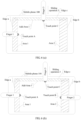
- FIG 4 (a) and FIG 4 (b) respectively show example cases of step 201 in actual application according to some embodiments of the present invention.
- a user first performs an outside-in sliding operation 1 from a screen edge a of the touchscreen 140 of the mobile phone 100 by using a finger 1. If the user performs, when the user does not release the action performed by using the finger 1 (which may also be understood as that the finger does not leave the touchscreen), an outside-in sliding operation 2 from another screen edge b of the touchscreen 140 by using a finger 2, for the mobile phone 100, it is determined that, in this case, the event described in step 201 occurs, to be specific, when a sliding operation performed from one edge of the touchscreen is not released, a sliding operation is performed from another edge of the touchscreen. Therefore, it is determined that a user operation triggers a procedure in which the terminal selects and locks a partial display area on the touchscreen based on the sliding operation.
- a user simultaneously performs outside-in sliding operations from a screen edge a and a screen edge b of the touchscreen 140 respectively by using a finger 1 and a finger 2. If neither the two sliding operations is released, for the mobile phone 100, it may be determined that the event described in step 201 occurs in this case, and further, it may be determined that a user operation triggers a procedure in which the terminal selects and locks a partial display area on the touchscreen based on the sliding operation.
- the terminal with the touchscreen detects that a sliding operation performed from one edge of the touchscreen is not released, if a sliding operation is performed from another edge of the touchscreen, execution of the procedure of selecting and locking a partial display area on the touchscreen based on the sliding operation is triggered.
- the procedure may be specifically step 202 and step 203 shown in FIG 2 .
- Step 202 The terminal selects a to-be-locked area on the touchscreen based on the first edge and the second edge of the touchscreen and respective touch point positions at which the first sliding operation and the second operation stop on the touchscreen.
- Step 203 The terminal locks the to-be-locked area.
- That a sliding operation "stops” described in this application is specifically an event that the terminal cannot continue to detect that a touch object that performs the sliding operation moves on the touchscreen.
- Typical examples include: The touch object stops moving on the touchscreen, touch of the touch object on the touchscreen is interrupted, or the touch object leaves the touchscreen. Before the sliding operation "stops", a touch point position of the sliding operation on the touchscreen changes, and after the sliding operation "stops", the touch point position of the sliding operation on the touchscreen does not change any longer.
- a stopping time sequence of the first sliding operation and the second sliding operation is not limited in descriptions of this application, and the first sliding operation and the second sliding operation may simultaneously stop, or may successively stop.
- the first sliding operation stops first
- the second sliding operation keeps sliding for specific duration before stopping.
- the terminal when performing step 202, determines, based on the first edge of the touchscreen and the touch point position at which the first sliding operation stops on the touchscreen, a to-be-locked area selected by the first sliding operation, and determines, based on the second edge of the touchscreen and the touch point position at which the second sliding operation stops on the touchscreen, a to-be-locked area selected by the second sliding operation, so that the to-be-locked area selected by the first sliding operation and the to-be-locked area selected by the second sliding operation may jointly constitute the selected to-be-locked area on the touchscreen.
- a specific manner used by the terminal to determine, based on the first edge of the touchscreen and the touch point position at which the first sliding operation stops on the touchscreen, the to-be-locked area selected by the first sliding operation may include but is not limited to the following.
- the terminal first determines the touch point position at which the first sliding operation stops on the touchscreen; the terminal further determines, based on the touch point position, a straight line that is parallel to the first edge and that passes through the touch point position; and further, the terminal may obtain, based on the determined straight line, the first edge, and other edges of the touchscreen, a closed area formed by the straight line and the edges.
- the closed area may be used as the to-be-locked area (a first closed area) selected by the first sliding operation.
- the to-be-locked area selected by the second sliding operation and determined by the terminal based on the second edge of the touchscreen and the touch point position at which the second sliding operation stops on the touchscreen may be specifically a closed area (a second closed area) formed by the second edge, a straight line that is parallel to the second edge and that passes through the touch point position at which the second sliding operation stops on the touchscreen, and other edges of the touchscreen.
- FIG 5 shows an example of a to-be-locked area selected by a sliding operation according to some embodiments of the present invention.
- a sliding operation 1 (which is equivalent to the first sliding operation) performed from a screen edge a (which is equivalent to the first edge) of the touchscreen 140 of the mobile phone 100 by using a finger 1
- a touch point position at which the sliding operation 1 stops on the touchscreen is a point A
- a to-be-locked area selected by the sliding operation 1 is a closed area Area 1 (which is equivalent to the first closed area) shown in FIG 5 .
- a sliding operation 2 (which is equivalent to the second sliding operation) performed from another screen edge b (which is equivalent to the second edge) of the touchscreen 140 by using a finger 2
- a touch point position at which the sliding operation 2 stops on the touchscreen is a point B
- a to-be-locked area selected by the sliding operation 2 is a closed area Area 2 (which is equivalent to the second closed area) shown in FIG 5 . Therefore, in the example shown in FIG 5 , the to-be-locked area selected by the terminal includes the closed area Area 1 and the closed area Area 2.
- the mobile phone 100 is still used as an example.
- the processor 180 may store position information of the currently locked area in the memory 120. Therefore, during subsequent use, for user touch information detected by the touchscreen, whether the user touches the locked area can be determined by reading the stored position information of the locked area, and further, when touch on the locked area is detected, the locked area does not respond to a screen touch operation of the user, but an unlocked area can still make a normal screen touch response based on a preset function definition.
- the terminal selects the to-be-locked area on the touchscreen based on the first edge and the second edge of the touchscreen and the respective touch point positions at which the first sliding operation and the second sliding operation stop on the touchscreen, so that the user can flexibly select a to-be-locked display area based on a requirement by using a sliding operation performed on the touchscreen by the user. Therefore, different user screen locking requirements can be met, and user experience can be improved.
- the foregoing embodiment of the present invention describes only an example case in which the terminal selects a to-be-locked area based on two different edges of the touchscreen.
- the terminal there are more than two edges of the touchscreen.
- the touchscreen of the mobile phone 100 shown in FIG 1 has four edges. Therefore, in some embodiments of the present invention, after triggering a procedure of selecting and locking a partial area on the touchscreen in step 201, the terminal may further detect another edge of the touchscreen other than the first edge and the second edge.
- the terminal after selecting, in step 202, the to-be-locked area on the touchscreen based on the first edge and the second edge of the touchscreen and the respective touch point positions at which the first sliding operation and the second sliding operation stop on the touchscreen, if a third sliding operation may be further performed from a third edge of the touchscreen when the terminal detects that the first sliding operation performed by the touch object does not leave the touchscreen, or the second sliding operation performed by the touch object does not leave the touchscreen, or neither the first sliding operation nor the second sliding operation performed by the touch object leaves the touchscreen, the terminal selects an additional to-be-locked area on the touchscreen based on the third edge and a touch point position at which the third sliding operation stops on the touchscreen. Further, when performing step 203, the terminal may lock the to-be-locked area determined by using step 202 and the additional to-be-locked area selected by the third sliding operation.
- the sliding operation performed by the touch object does not leave the touchscreen may specifically include: touch performed on the touchscreen by the touch object that performs the sliding operation is not interrupted or the touch object does not leave the touchscreen.
- a typical example of “leaving the touchscreen” includes a finger up event and the like.
- the third edge may be named a fourth edge, and the first edge, the second edge, and the third edge are edges but not a same edge.
- a specific example of the additional to-be-locked area selected by the terminal based on the third edge of the touchscreen and the touch point position at which the third sliding operation stops on the touchscreen may be a closed area (a third closed area) formed by the third edge, a straight line that is parallel to the third edge and that passes through the touch point position at which the third sliding operation stops on the touchscreen, and other edges of the touchscreen.
- the mobile phone 100 shown in FIG 1 is used as an example. It is assumed that four edges of the touchscreen of the mobile phone 100 are respectively a, b, c, and d. Based on the example of the sliding operation shown in FIG 4 (a) , it is assumed that the user first respectively performs sliding operations from an edge a and an edge b by using a finger 1 and a finger 2, to trigger a procedure of selecting and locking a partial display area.
- Area 1 and Area 2 in the example shown in FIG 5 constitute a selected to-be-locked area, and this is further used as an example case.
- the terminal may obtain, based on the edge c and a touch point position C at which the sliding operation 3 stops on the touchscreen, an additional to-be-locked area Add-Area 1 selected by the sliding operation 3. For example, in an example shown in FIG 6 (a) , Area 1, Area 2, and Add-Area 1 jointly constitute the area locked by the terminal in step 203.
- the terminal may obtain, based on the edge c and a touch point position C at which the sliding operation 3 stops on the touchscreen, an additional to-be-locked area Add-Area 1' selected by the sliding operation 3. For example, in an example shown in FIG 6 (b) , Area 1, Area 2, and Add-Area 1' jointly constitute the area locked by the terminal in step 203.
- the terminal may obtain, based on the edge d and a touch point position D at which the sliding operation 3 stops on the touchscreen, an additional to-be-locked area Add-Area 1" selected by the sliding operation 3.
- an additional to-be-locked area Add-Area 1" selected by the sliding operation 3.
- Area 1, Area 2, and Add-Area 1" jointly constitute the area locked by the terminal in step 203.
- the terminal may further select another additional to-be-locked area on the touchscreen based on the fourth edge and a touch point position at which the fourth sliding operation stops on the touchscreen. Further, when performing step 203, the terminal may lock the to-be-locked area determined by using step 202, the additional to-be-locked area selected by the third sliding operation, and the additional to-be-locked area selected by the fourth sliding operation.
- the fourth edge may be named a fifth edge
- the first edge, the second edge, the third edge, and the fourth edge are edges but not a same edge.
- a specific example of the additional to-be-locked area selected by the terminal based on the fourth edge of the touchscreen and the touch point position at which the fourth sliding operation stops on the touchscreen may be a closed area (a fourth closed area) formed by the fourth edge, a straight line that is parallel to the fourth edge and that passes through the touch point position at which the fourth sliding operation stops on the touchscreen, and other edges of the touchscreen.
- the mobile phone 100 shown in FIG 1 is still used as an example.
- Four edges of the touchscreen of the mobile phone 100 are respectively a, b, c, and d.
- the user first respectively performs sliding operations from the edge a, the edge b, and the edge c by using a finger 1, a finger 2, and a finger 3, to trigger selection of a partial display area, and selects Area 1, Area 2, and Add-Area 1 as to-be-locked areas, to be further used as an example case.
- the terminal may obtain, based on the edge d and a touch point position D at which the sliding operation 4 stops on the touchscreen, an additional to-be-locked area Add-Area 2 selected by the sliding operation 4. For example, in an example shown in FIG 7 , Area 1, Area 2, Add-Area 1, and Add-Area 2 jointly constitute the area locked by the terminal in step 203.
- the to-be-locked area finally locked by the terminal in step 203 may specifically include to-be-locked areas selected by the terminal based on sliding operations performed from any two screen edges of the touchscreen, and may further include a to-be-locked area additionally selected by a sliding operation that is performed from any one or more edges of the touchscreen and that is detected by the terminal based on the two sliding operations. Therefore, in the screen locking solution provided in the foregoing embodiment of the present invention, the user can quite flexibly select the to-be-locked display area based on a requirement by using different sliding operations performed on the touchscreen. Therefore, different user screen locking requirements can be met, and user experience can be improved.
- a straight line that is parallel to the edge and that passes through a touch point position at which the sliding operation stops on the touchscreen is used.
- a curve or a wavy line that passes through the touch point position at which the sliding operation stops on the touchscreen may be used, or a line type may be set by the user independently, so as to enrich user experience.
- the terminal may start to select the to-be-locked area when triggering execution of step 202 by using step 201 starts, and in a process in which movement of the sliding operation on the touchscreen can be continuously detected, the terminal dynamically selects a display area on the touchscreen as the touch object moves, and does not select, as a to-be-locked area corresponding to the slipping operation, the display area selected in this case until the slipping operation leaves the touchscreen.
- the mobile phone 100 shown in FIG 1 is used as an example.
- An area selected by the sliding operation 1 that is performed from the edge a may be a rectangular area that starts from the screen edge a and that changes with a touch point position at which the sliding operation 1 is performed on the touchscreen, and a rectangular area selected when the sliding operation 1 leaves the touchscreen is fixed as a to-be-locked area selected by the sliding operation 1.
- selection of the to-be-locked area is started when triggering execution of step 202 by using step 201 starts, and in a process of continuously detecting that the sliding operation moves on the touchscreen, and in a process in which movement of the sliding operation on the touchscreen can be continuously detected, the display area on the touchscreen is dynamically selected as the touch object moves.
- a coverage layer corresponding to the selected display area is created for the display area dynamically selected in the foregoing process.
- the coverage layer may be specifically above the selected display area, so that the selected area can be intuitively displayed to the user in a user interface in real time.
- the coverage layer is in any one of the following forms: a transparent layer, a translucent layer, a translucent layer in an animation effect, a translucent layer with a touch lock guidance message, or a translucent layer with visual information.
- step 202 display of the coverage layer corresponding to the selected to-be-locked area may be kept in specified duration, to prompt the user with the to-be-locked area selected by the user.
- step 203 the coverage layer is deleted.
- a special display effect (such as a translucent gray effect or a white effect) may be used for any rectangular area formed based on a finger and an edge at which a finger sliding operation is detected, to represent a selected to-be-locked area.
- the selected area Before the finger is lifted, the selected area may synchronously change (for example, the selected area may constantly move inward or outward) with finger sliding, to adjust a size of a selected display area.
- a to-be-locked area corresponding to this touch sliding operation is determined.
- all selected to-be-locked areas are determined.
- An area displayed in a special effect may be delayed for a short period of time (such as, half a second), to prompt an area locked by the user. Then, special effect display may be canceled, previous display may be restored, and the selected areas on the touchscreen are locked.
- a user operation may be a user sliding operation shown in FIG 8 (a) that is used as an example of sliding from two adjacent ends (two adjacent ends included by any screen edge of the touchscreen) of the touchscreen to the middle, or a user sliding operation shown in FIG 8 (b) that is used as an example of sliding from two diagonally opposite ends (two diagonal ends of the touchscreen) of the touchscreen to the middle.
- a recognition area with a preset size may be further set at a position of a touchscreen edge at a corner, so that when it is determined in step 201 that sliding operations are performed from different corners of the touchscreen, a to-be-locked area may be selected based on a to-be-locked area selection rule similar to that in the foregoing embodiment.
- FIG 9 (a) shows an example case of selecting a to-be-locked area according to some embodiments of the present invention.
- a to-be-locked area selected by sliding operations performed from two adjacent ends (such as a corner 1 and a corner 2 in the figure) of the touchscreen to the middle may be equivalent to a to-be-locked area selected by sliding operations performed from edges b, c, and d of the touchscreen to the middle.
- FIG 9 (b) shows an example case of selecting a to-be-locked area according to some embodiments of the present invention.
- a to-be-locked area selected by sliding operations performed from two opposite ends (such as a corner 1 and a corner 3 in the figure) of the touchscreen to the middle may be equivalent to a to-be-locked area selected by sliding operations performed from edges a, b, c, and d of the touchscreen to the middle.
- the user may still trigger selection of an unlocked area on the touchscreen again in a manner that is the same as that in the foregoing embodiment of the present invention, so that a new to-be-locked area is added, or the existing to-be-locked area is adjusted.
- adjusting the to-be-locked area before the to-be-locked area is locked may further include: deleting the selected to-be-locked area (the deletion herein may also be understood as lock cancellation). For example, a part of the selected to-be-locked area or the entire selected to-be-locked area may be deleted in the following manner.
- locking of the to-be-locked area corresponding to the operation may be terminated in response to the operation, and the operation may be a preset touch operation or a preset key pressing instruction.
- the touchscreen after locking the selected to-be-locked area by using the procedure shown in FIG 2 , when touch that is not corresponding to a preset unlock operation and that is on a locked area on the touchscreen is detected, the touchscreen is further prevented from responding to the touch, and a coverage layer corresponding to the locked area is further created, to remind the user that a touched area is the locked area.
- the coverage layer may be displayed for preset duration, or may be deleted in response to an event that the touch leaves the touchscreen.
- the preset unlock operation may include operations such as a smart key association function, a touch operation, a key pressing operation, a voice operation, and gesture sensing.
- the locked display area may be displayed by using a special effect (such as creating a translucent gray coverage layer or a white coverage layer), to remind the user that the current operation is performed in the locked display area, does not take effect, and gets no response.
- a special effect such as creating a translucent gray coverage layer or a white coverage layer
- the user is prompted with a position of the locked display area by using this effect.
- the special effect may be canceled accordingly, to respond to leaving of the user finger.
- FIG 10 shows an example case that occurs after a locked area is touched according to some embodiments of the present invention. It may be learned that, in the example shown in FIG 10 , the touchscreen does not respond to touch on a locked area, and prompts, by creating a translucent coverage layer, the user that a user operation is performed in the locked area. It should be understood that FIG 10 is only a typical example of prompting the user with the locked area, and in actual application, the user may also be prompted, by using a pop-up window, a voice, or a combination of a plurality of effects, that a current operation is performed in the locked area.
- the user may also set the locked area by using the foregoing method, to set permission of an application in the locked area.
- the user may set an additional password or gesture to trigger the corresponding application.
- the user may place an application with a high privacy level or a high security level in a specified locked area, so that another person cannot directly enter some applications, or a corresponding password or gesture is required when some applications in the locked area are triggered. In this manner, a child can be prevented from accidentally making a call or accidentally sending a message when playing a mobile phone, or a payment behavior not desired by the user can be prevented.
- the permission of the application in the locked area is not specifically limited in this embodiment of the present invention.
- the terminal with the touchscreen detects that the sliding operation performed from one edge of the touchscreen is not released, the sliding operation is performed from another edge of the touchscreen, and in this case, the to-be-locked area on the touchscreen is selected and locked based on the two edges of the touchscreen and the respective touch point positions at which the two sliding operations stop on the touchscreen.
- the foregoing embodiment of the present invention provides a screen locking solution of triggering partial screen locking based on the sliding operation, and a screen locking area is selected based on the sliding operation, so that the user can independently select and lock the to-be-locked area, thereby improving user experience.
- the user can trigger selection and locking of a partial display area on the touchscreen by performing the sliding operation on the touchscreen, and the user is allowed to flexibly select and lock a display area on the touchscreen based on a requirement by performing the sliding operation on the touchscreen. Therefore, it may be learned that, in the technical solution provided in this embodiment of the present invention, not only a screen can be partially locked, but the user is also allowed to flexibly select and adjust a to-be-locked display area on the touchscreen based on a requirement. Therefore, compared with an existing screen locking technical solution, this technical solution is more flexible, both screen locking experience and device holding experience of the user are improved, and especially for a handheld device with a larger touchscreen area, disadvantages of a small holding area and poor holding experience can be overcome.
- FIG 11 is a schematic flowchart of a screen locking method according to some other embodiments of the present invention.
- the procedure shown in FIG 11 may be implemented by using software programming or a combination of software and hardware, and may be specifically implemented on a terminal with a touchscreen, for example, on a mobile phone 100 with a touchscreen 140 shown in FIG 1 .
- the procedure of the screen locking method includes the following steps.
- Step 1101 The terminal detects that pressure applied on the touchscreen by a first sliding operation performed from a first edge of the touchscreen exceeds a specified threshold.
- Step 1102 The terminal selects a to-be-locked area on the touchscreen based on the first edge of the touchscreen and a touch point position at which the first sliding operation stops on the touchscreen.
- Step 1103 The terminal locks the to-be-locked area.
- an event used to trigger the terminal to select the to-be-locked area based on the sliding operation is that the pressure applied on the touchscreen by the sliding operation on the touchscreen exceeds the specified threshold.
- the touchscreen may be configured as a display panel and a touch panel, so that a touched position, a touched area, touch pressure, a touch capacitance, and the like are detected, and a capacitance change, a pressure change, and the like caused by touch input (such as a touch sliding operation performed from an edge area on the touchscreen) exerted on the touchscreen may be converted into an electrical input signal.
- touch input such as a touch sliding operation performed from an edge area on the touchscreen
- a corresponding signal may be transmitted to a touch controller.
- the touch controller may process the received signal, and then send corresponding data to the controller.
- the mobile phone 100 shown in FIG 1 is still used as an example.
- the touchscreen 140 or touchscreen software of the mobile phone 100 may continuously detect outside-in sliding actions performed by fingers from four edges of the touchscreen 140 and pressure applied on the touchscreen 140 by the actions.
- the user may simultaneously or successively start to perform outside-in sliding operations from any two or more screen edges (such as an edge a and an edge b shown in FIG 12 (b) ) of the touchscreen 140, if pressure applied on the touchscreen 140 by any one or both the two sliding operations exceeds a preset pressure threshold, it may be determined that the terminal is triggered to select the to-be-locked area based on the sliding operation of the user.
- any two or more screen edges such as an edge a and an edge b shown in FIG 12 (b)
- the event used to trigger the terminal to select the to-be-locked area based on the sliding operation is not limited to the foregoing two example cases, and any possible case in which a sliding operation is performed on the touchscreen and pressure applied by the sliding operation exceeds a threshold may be designed to trigger the terminal to select the to-be-locked area based on the sliding operation.
- the terminal may further be designed, with reference to another screen feature of the touchscreen (for example, with reference to a position or a speed), to trigger selection of the to-be-locked area based on the sliding operation. This is not described in detail in the present invention.
- a main difference between the method procedure shown in FIG 11 and the method procedure shown in FIG 2 is that events used to trigger the terminal to select the to-be-locked area based on the sliding operation are different.
- the event used to trigger the terminal to select the to-be-locked area based on the sliding operation is that at least one sliding operation (such as step 201 shown in FIG 2 ) is performed from a different edge of the touchscreen when at least one sliding operation performed from an edge of the touchscreen is not released.
- the event used to trigger the terminal to select the to-be-locked area based on the sliding operation is that pressure applied on the touchscreen by any sliding operation exceeds a specified threshold (such as step 1101 in FIG 11 ).
- the terminal may subsequently select the to-be-locked area based on the sliding operation by using a similar process, for example:
- the terminal may determine, in but without being limited to the following manner, the to-be-locked area selected by the first sliding operation detected in step 1101: The terminal uses a first closed area formed by the first edge, a straight line that is parallel to the first edge and that passes through the touch point position at which the first sliding operation stops on the touchscreen, and other edges of the touchscreen as a to-be-locked area selected by the first sliding operation.
- the selected to-be-locked area is mainly determined by the sliding operation performed by the user on the touchscreen, so that the to-be-locked area can be flexibly selected.
- the terminal may further detect another edge of the touchscreen other than the first edge.
- the terminal may further select, based on the second edge and a touch point position at which the second sliding operation stops on the touchscreen, an additional to-be-locked area selected by the second sliding operation on the touchscreen. Further, when performing step 1103, the terminal may lock the to-be-locked area determined by using step 1102 and the additional to-be-locked area selected by the second sliding operation.
- a specific example of the additional to-be-locked area selected by the terminal based on the second edge of the touchscreen and the touch point position at which the second sliding operation stops on the touchscreen may be a closed area (a second closed area) formed by the second edge, a straight line that is parallel to the second edge and that passes through the touch point position at which the second sliding operation stops on the touchscreen, and other edges of the touchscreen.
- the mobile phone 100 shown in FIG 1 is used as an example.
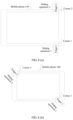
- FIG 13 (a) shows an example case of a to-be-locked area according to some embodiments of the present invention. It may be learned that a to-be-locked area Area 1 selected by a sliding operation 1 performed from an edge a is a closed rectangular area starting from the edge a and ending at a straight line that is parallel to the edge a and that passes through a touch point A at which the sliding operation 1 stops on the touchscreen. Area 1 constitutes the selected to-be-locked area.
- FIG 13 (b) shows an example case of a to-be-locked area according to some embodiments of the present invention. It may be learned that a to-be-locked area Area 1 selected by a sliding operation 1 performed from an edge a is a closed rectangular area starting from the edge a and ending at a straight line that is parallel to the edge a and that passes through a touch point A at which the sliding operation 1 stops on the touchscreen, and a to-be-locked area Area 2 selected by a sliding operation 2 performed from an edge b is a closed rectangular area starting from the edge b and ending at a straight line that is parallel to the edge b and that passes through a touch point position B at which the sliding operation 2 stops on the touchscreen. Area 1 and Area 2 constitute the selected to-be-locked area.
- the to-be-locked area may be determined based on a sliding operation that is performed on any edge of the touchscreen and that applies pressure exceeding a preset pressure threshold, and the sliding operation may be performed from any one or more edges of the touchscreen.
- a manner of selecting the to-be-locked area based on the sliding operation and the touchscreen edge may also be correspondingly adjusted.
- FIG 14 (a) shows an example case of a selected to-be-locked area according to some embodiments of the present invention.
- An area selected by a sliding operation that is performed from an adjacent end (a corner 1 shown in the figure) of the touchscreen to the middle and that applies pressure exceeding a preset pressure threshold may be set to be similar to an area selected by sliding operations that are performed from edges a and b of the touchscreen to the middle and that apply pressure exceeding the preset pressure threshold.
- FIG 14 (b) shows an example case of a selected to-be-locked area according to some embodiments of the present invention.
- An area selected by sliding operations that are performed from two opposite ends (such as a corner 1 and a corner 3 in the figure) of the touchscreen to the middle and that apply pressure exceeding the preset pressure threshold may be set to be similar to an area selected by sliding operations that are performed from four edges a, b, c, d of the touchscreen to the middle and that apply pressure exceeding the preset pressure threshold.
- step 1103 after the to-be-locked area is selected by using step 1102 in the procedure shown in FIG 11 , before the selected to-be-locked area is locked in step 1103, it may be further determined whether an operation used to delete a part of the selected to-be-locked area or the entire selected to-be-locked area is performed. If it is detected that the operation is performed, locking of an area corresponding to the operation is terminated in response to the operation.
- the operation used to delete a part of the selected to-be-locked area or the entire selected to-be-locked area may be a preset touch operation or a preset key pressing instruction.
- a coverage layer corresponding to the selected to-be-locked area is created for the to-be-locked area selected in the foregoing process.
- the coverage layer may be any one the following: a translucent layer, a translucent layer in an animation effect, a translucent layer with a touch lock guidance message, or a translucent layer with visual information.
- the terminal with the touchscreen detects that pressure applied on the touchscreen by a sliding operation that is performed from an edge of the touchscreen exceeds the specified threshold
- the to-be-locked area on the touchscreen is selected and locked based on the edge of the touchscreen and a touch point position at which the sliding operation stops on the touchscreen.
- a screen can be partially locked, and the user is allowed to flexibly select and adjust a to-be-locked display area on the touchscreen based on a requirement. Therefore, compared with an existing screen locking technical solution, this technical solution is more flexible, both screen locking experience and device holding experience of the user are improved, and especially for a handheld device with a larger touchscreen area, disadvantages of a small holding area and poor holding experience can be overcome.
- some embodiments of the present invention further provide a terminal, and the terminal may implement a procedure of the screen locking method embodiment shown in FIG 2 .
- the terminal provided in some embodiments of the present invention may be specifically implemented as the mobile phone 100 shown in FIG 1 .
- FIG 15 is a schematic structural diagram of a terminal according to some embodiments of the present invention. As shown in FIG 15 , the terminal includes a touchscreen 1501, a memory 1502, and a processor 1503.
- the processor 1503 is coupled to the touchscreen 1501.
- the touchscreen 1501 may be specifically configured to display a screen status of the terminal before a screen is locked, in a screen locking process, or after a screen is locked; and may be configured to sense an operation performed on the touchscreen.
- the memory 1502 is coupled to the processor 1503.
- the memory 1502 is configured to store computer executable program code, the program code includes an instruction, and when the processor 1503 executes the instruction, the instruction enables the terminal to perform a procedure of the screen locking method embodiment shown in FIG 2 of the present invention.
- the terminal provided in some embodiments of the present invention shown in FIG 15 may be configured to implement the procedure in the screen locking method embodiment shown in FIG 2 and procedures corresponding to some specific embodiments of the present invention of the screen locking method shown in FIG 2 .
- the procedure For specific implementation of the procedure, refer to descriptions in the foregoing method embodiments. To avoid description redundancy, details are not described herein again in this application.
- some embodiments of the present invention further provide a screen locking apparatus.
- the apparatus may be applied to a terminal with a touchscreen.
- a functional module of the apparatus may be implemented by hardware, software, or a combination of software and hardware, to perform the procedure in the screen locking method embodiment shown in FIG 2 .
- FIG 16 is a schematic structural diagram of a terminal according to some embodiments of the present invention. It should be understood that function modules shown in FIG 16 may be combined or separated into sub-blocks to implement a principle of the present invention. Therefore, descriptions in this application may support any possible combination or separation or further limitation of the modules in this application.
- the apparatus includes:
- the screen locking apparatus provided in some embodiments of the present invention shown in FIG 16 may be configured to implement the procedure in the screen locking method embodiment shown in FIG 2 and procedures corresponding to some specific embodiments of the present invention of the screen locking method shown in FIG 2 .
- the procedure For specific implementation of the procedure, refer to descriptions in the foregoing method embodiments. To avoid description redundancy, details are not described herein again in this application.
- some embodiments of the present invention further provide a terminal, and the terminal may implement a procedure of the screen locking method embodiment shown in FIG 11 .
- the terminal provided in some embodiments of the present invention may be specifically implemented as the mobile phone 100 shown in FIG 1 .
- FIG 17 is a schematic structural diagram of a terminal according to some embodiments of the present invention. As shown in FIG 17 , the terminal includes a touchscreen 1701, a memory 1702, and a processor 1703.
- the processor 1703 is coupled to the touchscreen 1701, the touchscreen 1701 is configured to display a screen status of the terminal before a screen is locked, in a screen locking process, or after a screen is locked, and is configured to sense an operation performed on the touchscreen, the memory 1702 is coupled to the processor 1703, the memory 1702 is configured to store computer executable program code, the program code includes an instruction, and when the processor 1703 executes the instruction, the instruction enables the terminal to perform the procedure of the screen locking method embodiment shown in FIG 11 of the present invention.
- the terminal provided in some embodiments of the present invention shown in FIG 17 may be configured to implement the procedure in the screen locking method embodiment shown in FIG 11 and procedures corresponding to some specific embodiments of the present invention of the screen locking method shown in FIG 11 .
- procedures corresponding to some specific embodiments of the present invention of the screen locking method shown in FIG 11 For specific implementation of the procedure, refer to descriptions in the foregoing method embodiments. To avoid description redundancy, details are not described herein again in this application.
- some embodiments of the present invention further provide a screen locking apparatus.
- the apparatus may be applied to a terminal with a touchscreen.
- a functional module of the apparatus may be implemented by hardware, software, or a combination of software and hardware, to perform the procedure in the screen locking method embodiment shown in FIG 11 .
- FIG 18 is a schematic structural diagram of a screen locking apparatus according to some embodiments of the present invention. It should be understood that function modules shown in FIG 18 may be combined or separated into sub-blocks to implement a principle of the present invention. Therefore, descriptions in this application may support any possible combination or separation or further limitation of the modules in this application.
- the apparatus includes:
- the screen locking apparatus provided in some embodiments of the present invention shown in FIG 18 may be configured to implement the procedure in the screen locking method embodiment shown in FIG 11 and procedures corresponding to some specific embodiments of the present invention of the screen locking method shown in FIG 11 .
- procedures corresponding to some specific embodiments of the present invention of the screen locking method shown in FIG 11 .
- specific implementation of the procedure refer to descriptions in the foregoing method embodiments. To avoid description redundancy, details are not described herein again in this application.
- these technologies may be implemented by modules (such as a program and a function) that implement functions described herein.
- Software code may be stored in a memory unit and executed by a processor.
- the memory unit may be implemented in the processor or outside the processor.
- These computer program instructions may be provided for a general-purpose computer, a dedicated computer, an embedded processor, or a processor of any other programmable data processing device to generate a machine, so that the instructions executed by a computer or a processor of any other programmable data processing device generate an apparatus for implementing a specific function in one or more processes in the flowcharts and/or in one or more blocks in the block diagrams.
- These computer program instructions may be stored in a computer readable memory that can instruct the computer or any other programmable data processing device to work in a specific manner, so that the instructions stored in the computer readable memory generate an artifact that includes an instruction apparatus.
- the instruction apparatus implements a specific function in one or more processes in the flowcharts and/or in one or more blocks in the block diagrams.
- These computer program instructions may be loaded onto a computer or another programmable data processing device, so that a series of operations and steps are performed on the computer or the another programmable device, thereby generating computer-implemented processing. Therefore, the instructions executed on the computer or the another programmable device provide steps for implementing a specific function in one or more processes in the flowcharts and/or in one or more blocks in the block diagrams.
Claims (7)
- Procédé de verrouillage d'écran, appliqué à un terminal avec un écran tactile, le procédé comprenant :
la détection (201), par le terminal, d'une première opération de glissement mise en oeuvre par un premier objet tactile à partir d'un premier bord de l'écran tactile ; la détection, par le terminal, d'une deuxième opération de glissement mise en oeuvre par un second objet tactile à partir d'un deuxième bord de l'écran tactile avant que la première opération de glissement ne soit libérée, dans lequel le premier bord est différent du deuxième bord ; et en réponse à la détection de la première opération de glissement et à la détection de la deuxième opération de glissement avant que la première opération de glissement ne soit libérée, le déclenchement, par le terminal, d'une procédure de sélection et verrouillage, la procédure de sélection et verrouillage comprenant :la sélection (202), par le terminal, d'une zone à verrouiller sur l'écran tactile en fonction du premier bord et du deuxième bord de l'écran tactile et de positions respectives de point tactile au niveau desquelles la première opération de glissement et la deuxième opération de glissement s'arrêtent sur l'écran tactile ; etle verrouillage (203), par le terminal, de la zone à verrouiller pour générer une zone verrouillée correspondante ;dans lequel chacune parmi la première opération de glissement et la deuxième opération de glissement est définie comme s'étant arrêtée lorsque le terminal ne détecte plus de mouvement de l'objet tactile correspondant ;après la sélection, par le terminal, d'une zone à verrouiller sur l'écran tactile, le procédé comprenant en outre :le réglage et l'affichage, par le terminal, d'une couche de couverture couvrant la zone à verrouiller ; dans lequella couche de couverture est l'une quelconque parmi les suivantes :une couche translucide, une couche translucide dans un effet d'animation, une couche translucide avec un message de guidage de verrouillage tactile, ou une couche translucide avec des informations visuelles ; etaprès le verrouillage, par le terminal, de la zone à verrouiller, le procédé comprenant en outre :la suppression, par le terminal, de la couche de couverture qui couvre la zone verrouillée et la restauration d'un affichage dans la zone verrouillée ;dans lequel lorsqu'une opération tactile qui n'est pas une opération de déverrouillage préréglée et qui est sur la zone verrouillée sur l'écran tactile est détectée, l'écran tactile ne répond pas à l'opération tactile et la couche de couverture couvrant la zone à verrouiller est affichée pour indiquer la zone verrouillée. - Procédé selon la revendication 1, dans lequel la zone à verrouiller comprend :une première zone fermée formée par le premier bord, une ligne droite qui est parallèle au premier bord et qui passe à travers la position de point tactile au niveau de laquelle la première opération de glissement s'arrête sur l'écran tactile, et d'autres bords de l'écran tactile ; etune deuxième zone fermée formée par le deuxième bord, une ligne droite qui est parallèle au deuxième bord et qui passe à travers la position de point tactile au niveau de laquelle la deuxième opération de glissement s'arrête sur l'écran tactile, et d'autres bords de l'écran tactile.
- Procédé selon la revendication 1 ou 2, après la sélection, par le terminal, d'une zone à verrouiller sur l'écran tactile, comprenant en outre :lorsque le terminal détecte qu'au moins l'une parmi la première opération de glissement et la deuxième opération de glissement mise en oeuvre par un objet tactile utilisé pour toucher l'écran tactile ne quitte pas l'écran tactile, la mise en oeuvre d'une troisième opération de glissement à partir d'un troisième bord de l'écran tactile ;la sélection, par le terminal, d'une première zone à verrouiller supplémentaire sur l'écran tactile en fonction du troisième bord et d'une position de point tactile au niveau de laquelle la troisième opération de glissement s'arrête sur l'écran tactile ; etle verrouillage, par le terminal, de la zone à verrouiller comprend :
le verrouillage, par le terminal, de la zone à verrouiller et de la première zone à verrouiller supplémentaire. - Procédé selon la revendication 3, dans lequel la première zone à verrouiller supplémentaire comprend :
une troisième zone fermée formée par le troisième bord, une ligne droite qui est parallèle au troisième bord et qui passe à travers la position de point tactile au niveau de laquelle la troisième opération de glissement s'arrête sur l'écran tactile, et les premier et deuxième bords de l'écran tactile. - Procédé selon la revendication 3 ou 4, après la sélection, par le terminal, d'une première zone à verrouiller supplémentaire sur l'écran tactile, comprenant en outre :lorsque le terminal détecte que l'une quelconque ou plusieurs quelconques parmi la première opération de glissement, la deuxième opération de glissement et la troisième opération de glissement mises en oeuvre par l'objet tactile utilisé pour toucher l'écran tactile ne quittent pas l'écran tactile, la mise en oeuvre d'une quatrième opération de glissement à partir d'un quatrième bord de l'écran tactile ;la sélection, par le terminal, d'une seconde zone à verrouiller supplémentaire sur l'écran tactile en fonction du quatrième bord et d'une position de point tactile au niveau de laquelle la quatrième opération de glissement s'arrête sur l'écran tactile ; etle verrouillage, par le terminal, de la zone à verrouiller comprend :
le verrouillage, par le terminal, de la zone à verrouiller, de la première zone à verrouiller supplémentaire, et de la seconde zone à verrouiller supplémentaire. - Procédé selon la revendication 5, dans lequel la seconde zone à verrouiller supplémentaire comprend :
une quatrième zone fermée formée par le quatrième bord, une ligne droite qui est parallèle au quatrième bord et qui passe à travers la position de point tactile au niveau de laquelle la quatrième opération de glissement s'arrête sur l'écran tactile, et les premier et deuxième bords de l'écran tactile. - Terminal (100), le terminal comprenant un écran tactile (140), une mémoire (120) et un processeur (180), le processeur étant couplé à l'écran tactile, l'écran tactile étant configuré pour afficher un état d'écran du terminal avant qu'un écran soit verrouillé, ou dans un processus de verrouillage à l'écran, ou après qu'un écran est verrouillé, et étant configuré pour détecter une opération mise en oeuvre sur l'écran tactile, la mémoire étant couplée au processeur, la mémoire étant configurée pour stocker un code de programme exécutable par ordinateur, le code de programme comprenant une instruction, et lorsque le processeur exécute l'instruction, l'instruction permettant au terminal de mettre en oeuvre le procédé de verrouillage d'écran selon l'une quelconque des revendications 1 à 6.
Applications Claiming Priority (1)
| Application Number | Priority Date | Filing Date | Title |
|---|---|---|---|
| PCT/CN2016/104148 WO2018076384A1 (fr) | 2016-10-31 | 2016-10-31 | Procédé de verrouillage d'écran, terminal et dispositif de verrouillage d'écran |
Publications (3)
| Publication Number | Publication Date |
|---|---|
| EP3528103A1 EP3528103A1 (fr) | 2019-08-21 |
| EP3528103A4 EP3528103A4 (fr) | 2019-10-23 |
| EP3528103B1 true EP3528103B1 (fr) | 2023-06-28 |
Family
ID=62024252
Family Applications (1)
| Application Number | Title | Priority Date | Filing Date |
|---|---|---|---|
| EP16919877.7A Active EP3528103B1 (fr) | 2016-10-31 | 2016-10-31 | Procédé de verrouillage d'écran, terminal et dispositif de verrouillage d'écran |
Country Status (5)
| Country | Link |
|---|---|
| US (1) | US20190260864A1 (fr) |
| EP (1) | EP3528103B1 (fr) |
| CN (1) | CN108700990B (fr) |
| HK (1) | HK1257013A1 (fr) |
| WO (1) | WO2018076384A1 (fr) |
Families Citing this family (3)
| Publication number | Priority date | Publication date | Assignee | Title |
|---|---|---|---|---|
| KR102444500B1 (ko) * | 2018-03-29 | 2022-09-20 | 가부시키가이샤 코나미 데지타루 엔타테인멘토 | 정보 처리 장치, 및 기록 매체에 저장된 컴퓨터 프로그램 |
| US11409430B2 (en) * | 2018-11-02 | 2022-08-09 | Benjamin Firooz Ghassabian | Screen stabilizer |
| US11409279B1 (en) * | 2019-09-26 | 2022-08-09 | Amazon Technologies, Inc. | Autonomously motile device with remote control |
Family Cites Families (10)
| Publication number | Priority date | Publication date | Assignee | Title |
|---|---|---|---|---|
| CN101021762A (zh) * | 2007-03-26 | 2007-08-22 | 宇龙计算机通信科技(深圳)有限公司 | 触摸屏的锁定装置及方法 |
| US9411459B2 (en) * | 2010-05-19 | 2016-08-09 | Lg Electronics Inc. | Mobile terminal and control method thereof |
| KR101685363B1 (ko) * | 2010-09-27 | 2016-12-12 | 엘지전자 주식회사 | 휴대 단말기 및 그 동작 방법 |
| CN103164132A (zh) * | 2011-12-14 | 2013-06-19 | 中兴通讯股份有限公司 | 便携式电子终端及其解锁方法和装置 |
| KR20130102298A (ko) * | 2012-03-07 | 2013-09-17 | 주식회사 팬택 | 휴대용 단말기 및 휴대용 단말기의 디스플레이 제어 방법 |
| KR20130110715A (ko) * | 2012-03-30 | 2013-10-10 | 삼성전자주식회사 | 플렉서블 베젤 제공 방법 및 장치 |
| KR102040857B1 (ko) * | 2012-07-17 | 2019-11-06 | 삼성전자주식회사 | 펜 인식 패널을 포함한 단말기의 기능 운용 방법 및 이를 지원하는 단말기 |
| CN104035606A (zh) * | 2013-03-07 | 2014-09-10 | 宏碁股份有限公司 | 触控面板的操作方法与电子装置 |
| KR102137240B1 (ko) * | 2013-04-16 | 2020-07-23 | 삼성전자주식회사 | 디스플레이 영역을 조절하기 위한 방법 및 그 방법을 처리하는 전자 장치 |
| CN103268197B (zh) * | 2013-04-28 | 2016-03-02 | 华为技术有限公司 | 一种锁定屏幕的方法、装置和终端设备 |
-
2016
- 2016-10-31 US US16/346,067 patent/US20190260864A1/en not_active Abandoned
- 2016-10-31 WO PCT/CN2016/104148 patent/WO2018076384A1/fr unknown
- 2016-10-31 CN CN201680077771.8A patent/CN108700990B/zh active Active
- 2016-10-31 EP EP16919877.7A patent/EP3528103B1/fr active Active
-
2018
- 2018-12-17 HK HK18116134.3A patent/HK1257013A1/zh unknown
Also Published As
| Publication number | Publication date |
|---|---|
| HK1257013A1 (zh) | 2019-10-11 |
| EP3528103A4 (fr) | 2019-10-23 |
| US20190260864A1 (en) | 2019-08-22 |
| CN108700990A (zh) | 2018-10-23 |
| WO2018076384A1 (fr) | 2018-05-03 |
| CN108700990B (zh) | 2020-10-27 |
| EP3528103A1 (fr) | 2019-08-21 |
Similar Documents
| Publication | Publication Date | Title |
|---|---|---|
| KR102240088B1 (ko) | 애플리케이션 스위칭 방법, 디바이스 및 그래픽 사용자 인터페이스 | |
| EP2508972B1 (fr) | Dispositif électronique portable et son procédé de commande | |
| US9116663B2 (en) | Method for changing device modes of an electronic device connected to a docking station and an electronic device configured for same | |
| KR102545602B1 (ko) | 전자 장치 및 그의 동작 방법 | |
| EP2619646B1 (fr) | Dispositif électronique portable et son procédé de commande | |
| US20200183574A1 (en) | Multi-Task Operation Method and Electronic Device | |
| EP3525075B1 (fr) | Procédé pour l'éclairage d'un écran d'un terminal à deux écrans, et terminal | |
| US20140078091A1 (en) | Terminal Device and Method for Quickly Starting Program | |
| US20170199662A1 (en) | Touch operation method and apparatus for terminal | |
| US9250801B2 (en) | Unlocking method, portable electronic device and touch-sensitive device | |
| US11941910B2 (en) | User interface display method of terminal, and terminal | |
| KR20180108761A (ko) | 데이터 처리 방법 및 전자 디바이스 | |
| US9760189B2 (en) | Method and apparatus for controlling touch-key operation | |
| US8810529B2 (en) | Electronic device and method of controlling same | |
| EP3528103B1 (fr) | Procédé de verrouillage d'écran, terminal et dispositif de verrouillage d'écran | |
| US20200019366A1 (en) | Data Processing Method and Mobile Device | |
| CA2798684C (fr) | Methode pour modifier les modes de dispositif d'un dispositif electronique branche a une station d'accueil et dispositif electronique configure a cette fin | |
| EP3674867B1 (fr) | Procédé d'interaction homme-ordinateur et dispositif électronique | |
| EP3457269B1 (fr) | Dispositif électronique et procédé de fonctionnement à une seule main | |
| US20130293483A1 (en) | Selectable object display method and apparatus | |
| JP5624662B2 (ja) | 電子機器、表示制御方法およびプログラム | |
| CA2767707C (fr) | Dispositif electronique et sa methode de commande |
Legal Events
| Date | Code | Title | Description |
|---|---|---|---|
| STAA | Information on the status of an ep patent application or granted ep patent |
Free format text: STATUS: THE INTERNATIONAL PUBLICATION HAS BEEN MADE |
|
| PUAI | Public reference made under article 153(3) epc to a published international application that has entered the european phase |
Free format text: ORIGINAL CODE: 0009012 |
|
| STAA | Information on the status of an ep patent application or granted ep patent |
Free format text: STATUS: REQUEST FOR EXAMINATION WAS MADE |
|
| 17P | Request for examination filed |
Effective date: 20190515 |
|
| AK | Designated contracting states |
Kind code of ref document: A1 Designated state(s): AL AT BE BG CH CY CZ DE DK EE ES FI FR GB GR HR HU IE IS IT LI LT LU LV MC MK MT NL NO PL PT RO RS SE SI SK SM TR |
|
| AX | Request for extension of the european patent |
Extension state: BA ME |
|
| A4 | Supplementary search report drawn up and despatched |
Effective date: 20190920 |
|
| RIC1 | Information provided on ipc code assigned before grant |
Ipc: G06F 3/0488 20130101AFI20190916BHEP Ipc: G06F 3/0484 20130101ALI20190916BHEP |
|
| DAV | Request for validation of the european patent (deleted) | ||
| DAX | Request for extension of the european patent (deleted) | ||
| RAP1 | Party data changed (applicant data changed or rights of an application transferred) |
Owner name: HONOR DEVICE CO., LTD. |
|
| STAA | Information on the status of an ep patent application or granted ep patent |
Free format text: STATUS: EXAMINATION IS IN PROGRESS |
|
| STAA | Information on the status of an ep patent application or granted ep patent |
Free format text: STATUS: EXAMINATION IS IN PROGRESS |
|
| 17Q | First examination report despatched |
Effective date: 20211126 |
|
| GRAP | Despatch of communication of intention to grant a patent |
Free format text: ORIGINAL CODE: EPIDOSNIGR1 |
|
| STAA | Information on the status of an ep patent application or granted ep patent |
Free format text: STATUS: GRANT OF PATENT IS INTENDED |
|
| INTG | Intention to grant announced |
Effective date: 20230224 |
|
| GRAS | Grant fee paid |
Free format text: ORIGINAL CODE: EPIDOSNIGR3 |
|
| GRAA | (expected) grant |
Free format text: ORIGINAL CODE: 0009210 |
|
| STAA | Information on the status of an ep patent application or granted ep patent |
Free format text: STATUS: THE PATENT HAS BEEN GRANTED |
|
| AK | Designated contracting states |
Kind code of ref document: B1 Designated state(s): AL AT BE BG CH CY CZ DE DK EE ES FI FR GB GR HR HU IE IS IT LI LT LU LV MC MK MT NL NO PL PT RO RS SE SI SK SM TR |
|
| REG | Reference to a national code |
Ref country code: CH Ref legal event code: EP |
|
| REG | Reference to a national code |
Ref country code: AT Ref legal event code: REF Ref document number: 1583292 Country of ref document: AT Kind code of ref document: T Effective date: 20230715 |
|
| REG | Reference to a national code |
Ref country code: IE Ref legal event code: FG4D |
|
| REG | Reference to a national code |
Ref country code: DE Ref legal event code: R096 Ref document number: 602016080728 Country of ref document: DE |
|
| REG | Reference to a national code |
Ref country code: NL Ref legal event code: FP |
|
| REG | Reference to a national code |
Ref country code: LT Ref legal event code: MG9D |
|
| PG25 | Lapsed in a contracting state [announced via postgrant information from national office to epo] |
Ref country code: SE Free format text: LAPSE BECAUSE OF FAILURE TO SUBMIT A TRANSLATION OF THE DESCRIPTION OR TO PAY THE FEE WITHIN THE PRESCRIBED TIME-LIMIT Effective date: 20230628 Ref country code: NO Free format text: LAPSE BECAUSE OF FAILURE TO SUBMIT A TRANSLATION OF THE DESCRIPTION OR TO PAY THE FEE WITHIN THE PRESCRIBED TIME-LIMIT Effective date: 20230928 |
|
| PGFP | Annual fee paid to national office [announced via postgrant information from national office to epo] |
Ref country code: NL Payment date: 20230915 Year of fee payment: 8 Ref country code: GB Payment date: 20230907 Year of fee payment: 8 |
|
| REG | Reference to a national code |
Ref country code: AT Ref legal event code: MK05 Ref document number: 1583292 Country of ref document: AT Kind code of ref document: T Effective date: 20230628 |
|
| PG25 | Lapsed in a contracting state [announced via postgrant information from national office to epo] |
Ref country code: RS Free format text: LAPSE BECAUSE OF FAILURE TO SUBMIT A TRANSLATION OF THE DESCRIPTION OR TO PAY THE FEE WITHIN THE PRESCRIBED TIME-LIMIT Effective date: 20230628 Ref country code: LV Free format text: LAPSE BECAUSE OF FAILURE TO SUBMIT A TRANSLATION OF THE DESCRIPTION OR TO PAY THE FEE WITHIN THE PRESCRIBED TIME-LIMIT Effective date: 20230628 Ref country code: LT Free format text: LAPSE BECAUSE OF FAILURE TO SUBMIT A TRANSLATION OF THE DESCRIPTION OR TO PAY THE FEE WITHIN THE PRESCRIBED TIME-LIMIT Effective date: 20230628 Ref country code: HR Free format text: LAPSE BECAUSE OF FAILURE TO SUBMIT A TRANSLATION OF THE DESCRIPTION OR TO PAY THE FEE WITHIN THE PRESCRIBED TIME-LIMIT Effective date: 20230628 Ref country code: GR Free format text: LAPSE BECAUSE OF FAILURE TO SUBMIT A TRANSLATION OF THE DESCRIPTION OR TO PAY THE FEE WITHIN THE PRESCRIBED TIME-LIMIT Effective date: 20230929 |
|
| PG25 | Lapsed in a contracting state [announced via postgrant information from national office to epo] |
Ref country code: FI Free format text: LAPSE BECAUSE OF FAILURE TO SUBMIT A TRANSLATION OF THE DESCRIPTION OR TO PAY THE FEE WITHIN THE PRESCRIBED TIME-LIMIT Effective date: 20230628 |
|
| PG25 | Lapsed in a contracting state [announced via postgrant information from national office to epo] |
Ref country code: SK Free format text: LAPSE BECAUSE OF FAILURE TO SUBMIT A TRANSLATION OF THE DESCRIPTION OR TO PAY THE FEE WITHIN THE PRESCRIBED TIME-LIMIT Effective date: 20230628 |
|
| PG25 | Lapsed in a contracting state [announced via postgrant information from national office to epo] |
Ref country code: ES Free format text: LAPSE BECAUSE OF FAILURE TO SUBMIT A TRANSLATION OF THE DESCRIPTION OR TO PAY THE FEE WITHIN THE PRESCRIBED TIME-LIMIT Effective date: 20230628 |
|
| PG25 | Lapsed in a contracting state [announced via postgrant information from national office to epo] |
Ref country code: IS Free format text: LAPSE BECAUSE OF FAILURE TO SUBMIT A TRANSLATION OF THE DESCRIPTION OR TO PAY THE FEE WITHIN THE PRESCRIBED TIME-LIMIT Effective date: 20231028 |
|
| PG25 | Lapsed in a contracting state [announced via postgrant information from national office to epo] |
Ref country code: SM Free format text: LAPSE BECAUSE OF FAILURE TO SUBMIT A TRANSLATION OF THE DESCRIPTION OR TO PAY THE FEE WITHIN THE PRESCRIBED TIME-LIMIT Effective date: 20230628 Ref country code: SK Free format text: LAPSE BECAUSE OF FAILURE TO SUBMIT A TRANSLATION OF THE DESCRIPTION OR TO PAY THE FEE WITHIN THE PRESCRIBED TIME-LIMIT Effective date: 20230628 Ref country code: RO Free format text: LAPSE BECAUSE OF FAILURE TO SUBMIT A TRANSLATION OF THE DESCRIPTION OR TO PAY THE FEE WITHIN THE PRESCRIBED TIME-LIMIT Effective date: 20230628 Ref country code: PT Free format text: LAPSE BECAUSE OF FAILURE TO SUBMIT A TRANSLATION OF THE DESCRIPTION OR TO PAY THE FEE WITHIN THE PRESCRIBED TIME-LIMIT Effective date: 20231030 Ref country code: IS Free format text: LAPSE BECAUSE OF FAILURE TO SUBMIT A TRANSLATION OF THE DESCRIPTION OR TO PAY THE FEE WITHIN THE PRESCRIBED TIME-LIMIT Effective date: 20231028 Ref country code: ES Free format text: LAPSE BECAUSE OF FAILURE TO SUBMIT A TRANSLATION OF THE DESCRIPTION OR TO PAY THE FEE WITHIN THE PRESCRIBED TIME-LIMIT Effective date: 20230628 Ref country code: EE Free format text: LAPSE BECAUSE OF FAILURE TO SUBMIT A TRANSLATION OF THE DESCRIPTION OR TO PAY THE FEE WITHIN THE PRESCRIBED TIME-LIMIT Effective date: 20230628 Ref country code: CZ Free format text: LAPSE BECAUSE OF FAILURE TO SUBMIT A TRANSLATION OF THE DESCRIPTION OR TO PAY THE FEE WITHIN THE PRESCRIBED TIME-LIMIT Effective date: 20230628 Ref country code: AT Free format text: LAPSE BECAUSE OF FAILURE TO SUBMIT A TRANSLATION OF THE DESCRIPTION OR TO PAY THE FEE WITHIN THE PRESCRIBED TIME-LIMIT Effective date: 20230628 |
|
| PGFP | Annual fee paid to national office [announced via postgrant information from national office to epo] |
Ref country code: DE Payment date: 20230906 Year of fee payment: 8 |
|
| PG25 | Lapsed in a contracting state [announced via postgrant information from national office to epo] |
Ref country code: PL Free format text: LAPSE BECAUSE OF FAILURE TO SUBMIT A TRANSLATION OF THE DESCRIPTION OR TO PAY THE FEE WITHIN THE PRESCRIBED TIME-LIMIT Effective date: 20230628 |