EP3528064B1 - Control system and associated method for commissioning, controlling and monitoring current supply components - Google Patents
Control system and associated method for commissioning, controlling and monitoring current supply components Download PDFInfo
- Publication number
- EP3528064B1 EP3528064B1 EP18156846.0A EP18156846A EP3528064B1 EP 3528064 B1 EP3528064 B1 EP 3528064B1 EP 18156846 A EP18156846 A EP 18156846A EP 3528064 B1 EP3528064 B1 EP 3528064B1
- Authority
- EP
- European Patent Office
- Prior art keywords
- power supply
- unit
- assigned
- units
- supply components
- Prior art date
- Legal status (The legal status is an assumption and is not a legal conclusion. Google has not performed a legal analysis and makes no representation as to the accuracy of the status listed.)
- Active
Links
- 238000000034 method Methods 0.000 title claims description 61
- 238000012544 monitoring process Methods 0.000 title claims description 11
- 238000004891 communication Methods 0.000 claims description 101
- 230000008859 change Effects 0.000 claims description 17
- 230000004044 response Effects 0.000 claims description 4
- 230000008569 process Effects 0.000 description 31
- 230000005540 biological transmission Effects 0.000 description 14
- 238000012545 processing Methods 0.000 description 11
- 238000012546 transfer Methods 0.000 description 6
- 238000013461 design Methods 0.000 description 5
- 238000005516 engineering process Methods 0.000 description 4
- 238000006243 chemical reaction Methods 0.000 description 3
- 238000004458 analytical method Methods 0.000 description 2
- 238000013475 authorization Methods 0.000 description 2
- 230000008901 benefit Effects 0.000 description 2
- 238000013500 data storage Methods 0.000 description 2
- 238000011161 development Methods 0.000 description 2
- 230000010354 integration Effects 0.000 description 2
- 238000004519 manufacturing process Methods 0.000 description 2
- 239000003990 capacitor Substances 0.000 description 1
- 230000001419 dependent effect Effects 0.000 description 1
- 230000000694 effects Effects 0.000 description 1
- 238000004146 energy storage Methods 0.000 description 1
- 230000003993 interaction Effects 0.000 description 1
- 238000007726 management method Methods 0.000 description 1
- 238000005259 measurement Methods 0.000 description 1
- 238000012986 modification Methods 0.000 description 1
- 230000004048 modification Effects 0.000 description 1
Images
Classifications
-
- G—PHYSICS
- G06—COMPUTING; CALCULATING OR COUNTING
- G06F—ELECTRIC DIGITAL DATA PROCESSING
- G06F1/00—Details not covered by groups G06F3/00 - G06F13/00 and G06F21/00
- G06F1/26—Power supply means, e.g. regulation thereof
- G06F1/28—Supervision thereof, e.g. detecting power-supply failure by out of limits supervision
-
- G—PHYSICS
- G05—CONTROLLING; REGULATING
- G05B—CONTROL OR REGULATING SYSTEMS IN GENERAL; FUNCTIONAL ELEMENTS OF SUCH SYSTEMS; MONITORING OR TESTING ARRANGEMENTS FOR SUCH SYSTEMS OR ELEMENTS
- G05B19/00—Programme-control systems
- G05B19/02—Programme-control systems electric
- G05B19/04—Programme control other than numerical control, i.e. in sequence controllers or logic controllers
- G05B19/042—Programme control other than numerical control, i.e. in sequence controllers or logic controllers using digital processors
- G05B19/0423—Input/output
-
- G—PHYSICS
- G05—CONTROLLING; REGULATING
- G05B—CONTROL OR REGULATING SYSTEMS IN GENERAL; FUNCTIONAL ELEMENTS OF SUCH SYSTEMS; MONITORING OR TESTING ARRANGEMENTS FOR SUCH SYSTEMS OR ELEMENTS
- G05B19/00—Programme-control systems
- G05B19/02—Programme-control systems electric
- G05B19/04—Programme control other than numerical control, i.e. in sequence controllers or logic controllers
- G05B19/042—Programme control other than numerical control, i.e. in sequence controllers or logic controllers using digital processors
- G05B19/0426—Programming the control sequence
-
- G—PHYSICS
- G06—COMPUTING; CALCULATING OR COUNTING
- G06F—ELECTRIC DIGITAL DATA PROCESSING
- G06F1/00—Details not covered by groups G06F3/00 - G06F13/00 and G06F21/00
- G06F1/26—Power supply means, e.g. regulation thereof
-
- G—PHYSICS
- G06—COMPUTING; CALCULATING OR COUNTING
- G06F—ELECTRIC DIGITAL DATA PROCESSING
- G06F1/00—Details not covered by groups G06F3/00 - G06F13/00 and G06F21/00
- G06F1/26—Power supply means, e.g. regulation thereof
- G06F1/263—Arrangements for using multiple switchable power supplies, e.g. battery and AC
-
- H—ELECTRICITY
- H02—GENERATION; CONVERSION OR DISTRIBUTION OF ELECTRIC POWER
- H02J—CIRCUIT ARRANGEMENTS OR SYSTEMS FOR SUPPLYING OR DISTRIBUTING ELECTRIC POWER; SYSTEMS FOR STORING ELECTRIC ENERGY
- H02J50/00—Circuit arrangements or systems for wireless supply or distribution of electric power
- H02J50/80—Circuit arrangements or systems for wireless supply or distribution of electric power involving the exchange of data, concerning supply or distribution of electric power, between transmitting devices and receiving devices
-
- H—ELECTRICITY
- H04—ELECTRIC COMMUNICATION TECHNIQUE
- H04L—TRANSMISSION OF DIGITAL INFORMATION, e.g. TELEGRAPHIC COMMUNICATION
- H04L67/00—Network arrangements or protocols for supporting network services or applications
- H04L67/01—Protocols
- H04L67/12—Protocols specially adapted for proprietary or special-purpose networking environments, e.g. medical networks, sensor networks, networks in vehicles or remote metering networks
-
- G—PHYSICS
- G05—CONTROLLING; REGULATING
- G05B—CONTROL OR REGULATING SYSTEMS IN GENERAL; FUNCTIONAL ELEMENTS OF SUCH SYSTEMS; MONITORING OR TESTING ARRANGEMENTS FOR SUCH SYSTEMS OR ELEMENTS
- G05B19/00—Programme-control systems
- G05B19/02—Programme-control systems electric
- G05B19/418—Total factory control, i.e. centrally controlling a plurality of machines, e.g. direct or distributed numerical control [DNC], flexible manufacturing systems [FMS], integrated manufacturing systems [IMS], computer integrated manufacturing [CIM]
- G05B19/4185—Total factory control, i.e. centrally controlling a plurality of machines, e.g. direct or distributed numerical control [DNC], flexible manufacturing systems [FMS], integrated manufacturing systems [IMS], computer integrated manufacturing [CIM] characterised by the network communication
-
- G—PHYSICS
- G05—CONTROLLING; REGULATING
- G05B—CONTROL OR REGULATING SYSTEMS IN GENERAL; FUNCTIONAL ELEMENTS OF SUCH SYSTEMS; MONITORING OR TESTING ARRANGEMENTS FOR SUCH SYSTEMS OR ELEMENTS
- G05B2219/00—Program-control systems
- G05B2219/20—Pc systems
- G05B2219/25—Pc structure of the system
- G05B2219/25318—Power supply module in common for all modules
Definitions
- the present invention relates to a control system for power supply components, such as electrical power supplies, electrical fuses, measuring units, etc. of at least one system, from which an energy supply of control and/or computer units of the at least one system is monitored and controlled. Furthermore, the present invention also relates to an associated method for commissioning, controlling and monitoring power components of the at least one system with the control system according to the invention.
- An automation system or system for short, is generally referred to as a fully or partially automated industrial system for manufacturing products or controlling processes.
- industrial systems usually include control and/or computer units such as so-called industrial PCs and/or intelligent electronic, usually microprocessor-based devices (e.g. control devices, protection devices, pressure and temperature transmitters, flow meters, Actuators, programmable logic controllers, etc.), which control, monitor and/or control system-internal or system-specific processes.
- microprocessor-based devices e.g. control devices, protection devices, pressure and temperature transmitters, flow meters, Actuators, programmable logic controllers, etc.
- Power supply components are used in a system to supply energy to the control and/or computer units.
- Power supply components include all components in a current path such as electrical power supplies and/or switching power supplies, electrical fuses, Current storage (e.g. accumulator, capacitor, superconducting magnetic energy storage, etc.), measuring units, etc. are understood, which monitor, control and ensure the supply of energy to the respective control and/or computer unit via this current path and thus ensure that processes in the system are as trouble-free as possible Provide facility. Therefore, applications in industrial systems place special demands on the power supply components. For example, flexible and simple configuration and commissioning play an important role.
- cloud computing which provides the provision of IT infrastructure (e.g. storage space, computing power, application software) as a service over the Internet describes applications of importance which are operated on possibly distributed computer units (e.g. servers) and whose range of functions is made available to a user online or via the Internet.
- IT infrastructure e.g. storage space, computing power, application software
- FDT Field Device Tool
- FDI Field Device Integration
- the FDI technology is based on a client-server architecture in which the field devices are managed centrally using a central processing unit - a server. A configuration of each field device within a topology of the system is stored on this server. For the actual configuration of the field devices, a configuration tool is provided, which is set up to Manage the configuration of the field devices or the FDI clients.
- Changes are first written to the server and then transmitted to the respective field device, whereby an existing communication connection between the server and the field device or FDI client is necessary and, if necessary, a relatively high load on the respective field device may arise due to the data transmission.
- the FDI concept is primarily limited to field devices.
- the system described therefore has the disadvantage that the server application is executed directly on the control device, which means that the control device has a high level of data complexity and is additionally burdened by data communication and data processing.
- the selected server-client architecture limits the relationship between a server application on the control device and one or only a few client applications. If multiple client applications are accessed, the server application or the control device can be overloaded, as the communication resources of automation components are usually tailored to the functionality required in the respective system or corresponding to the area of application. For one Further communication, such as with configuration applications, etc., usually only reserve resources are available.
- a switching power supply with a web interface for connection to a communication network and a method for remotely configuring a switching power supply for use in industrial plants are known.
- the solution described in these two documents is based on the power supply component or the switching power supply having a web server, which is used to transmit data (e.g. operating parameters, process data, etc.) via a web browser to a configuration unit (e.g. PC, mobile device ) to configure, change and/or control.
- Efficiency usually plays a significant role in industrial power supply components. Therefore, the selection of computing and communication units installed in the power supply components (e.g. processors, input/output bandwidth, etc.) as well as the measurement of the storage capacity are limited. There is also high cost pressure when selecting the electronic components used. Therefore, the resources for data processing and data communication in power supply components are usually tailored to the core tasks. For further communication tasks (e.g. data exchange with the web browser application, access to the web server, etc.), power supply components usually only provide reserve resources.
- a power supply device which has several power supply components.
- the power supply components are each provided with a communication interface and are connected to a common analysis and control unit via this communication interface and a communication channel.
- the analysis and control unit controls load management of the power supply components.
- the WO 2015/169355 A1 discloses a device and a method for consistent set operations of data-modified OPC UA calls. Communication between the client and server of a client/server system is carried out using the OPC-UA communication protocol.
- OPC UA server calls are used for the interaction between client and server and logically related OPC UA server calls are combined by a client into a server call set, whereby the individual OPC UA server calls in the server call set are transmitted independently of each other.
- the invention is therefore based on the object of specifying a control system and an associated method through which power supply components in industrial systems can be configured, controlled and monitored in a platform-independent, flexible and simple and cost-effective manner, and which have the lowest possible burden due to data transmission and data processing for the have respective power supply components.
- a control system for power supply components of at least one system, from which an energy supply to control and/or computer units of the at least one system is monitored and controlled and thus ensured.
- This control system includes a central server unit, client units and local server units.
- a database for storing specific data and/or parameters of the respective power supply components such as device information, configuration parameters, version data, etc. is assigned to the central server unit.
- the client units are set up to communicate with the power supply components or with the local server units and to transmit the specific data and/or parameters from and to the power supply units. This requires each power supply component connected and identified via a communications network a separate client unit can be generated.
- the local server units are permanently assigned to the respective power supply components and set up for communication with the respective client units.
- the main aspect of the solution proposed according to the invention is that a corresponding communication and data processing architecture of the control system according to the invention keeps the load on the power supply components due to data communication and data processing as low as possible.
- An image of the respective specific data and/or parameters of the power supply components used in at least one system is implemented in the central server unit or in the associated database, which can be accessed largely without restriction for configuration, administration, control and monitoring purposes.
- Data transmission or communication with the respective power supply components, which are connected and identified with the control system via a communication network is limited to a few necessary accesses using the respective client units generated for the respective power supply units - in particular in order to transfer the data and/or parameters between local server units or .
- the central server unit with the assigned database thus has the effect of a "data hub", through which virtual instances of the respective power supply components are represented and the communication and data technology load on the individual power supply components is significantly reduced.
- central server unit client units, which can be generated for each identified power supply component and from which the communication with the respective power supply component or the respectively permanently assigned local server unit, and local server units, which are fixed to the power supply components assigned, enables a largely platform- and device-independent and flexible design of the control system.
- the control system can therefore run on different hardware architecture variants (e.g. stationary PC system, distributed computer system, cloud computing) without functional restrictions.
- the communication and data processing architecture of the control system according to the invention enables a freely scalable server-client relationship, ideally an n-to-m relationship.
- a 1-to-1 relationship is resolved between generatable client units and power supply components or the server units permanently assigned to them.
- the central server unit is accessed for configuration, administration, control and monitoring purposes - for example by means of client applications, the number of which can be predetermined, for example, by the configuration, capacity, etc. of the central server unit and the number of which is therefore independent of the number of identified and used the control system according to the invention is controlled and monitored power supply components.
- At least one input/output unit can also be connected.
- the specific data and/or parameters for the respective power supply components can be input, output and/or changed via this at least one input/output unit.
- the at least one input/output unit is connected using an application, in particular a web application.
- Input, output and/or change of the specific data and/or parameters for the respective power supply components can be carried out using a web browser, with a standardized Internet or web browser advantageously being able to be used as a user interface for the at least one input/output unit.
- a stationary PC can be installed without any additional effort or without any restrictions on its functionality PC systems and mobile devices (e.g.
- tablet PC handheld, etc.
- cloud computing via which, for example, the input/output unit or the display of the user interface as well as access to the functionalities of the control system according to the invention, in particular to the central server unit, are made available by means of an application.
- the input, output and/or changes of specific data and/or parameters for the power supply components can be carried out online and offline via the input/output unit.
- inputs/outputs and/or changes to data and/or parameters are carried out online using an input/output unit, there is a communication connection between the respective power supply component or the local server unit permanently assigned to the respective power supply component and the respective client unit.
- Off-line means that for the respective inputs/outputs and/or changes to data or parameters, there is no communication connection between the client unit and the respective power supply component or the assigned local server unit or that no client unit has yet been generated for the corresponding power supply component.
- offline operation only the central server unit or the corresponding data/parameters from the assigned database are accessed via the input/output unit.
- configurations for power supply components of a system can be planned and prepared without data and communication load on power supply components of a system or in a system planning phase in which, for example, the types of power supply components are selected but the power supply components themselves are not yet physically present , verified, checked for errors, admissibility and inconsistencies and, if necessary, simulated.
- template units so-called templates
- templates are provided for generating the respective client units.
- These template units represent a kind of “framework” for the respective client units, with part of the respective data structure and functional design already being specified. Missing parts such as current data, parameters and structures specific to the identified power supply component are added when the client unit is generated.
- the respective client unit can be dynamically generated quickly when a power supply component is identified and the load on the respective power supply component due to data communication, etc. can be kept low.
- An expedient embodiment of the control system according to the invention provides that a gateway unit - ie a switching unit - is also provided, to which a local server unit is assigned. Power supply components can be connected via the gateway unit using a serial interface for point-to-point connections such as USB interface, binary interface, etc. For communication with the local server unit permanently assigned to the gateway unit, a client unit can be generated, which communicates with the power supply component connected via the gateway unit using the gateway unit.
- the control system according to the invention can also be used to control and monitor power supply components without much effort, which, for example, do not have a suitable interface (e.g. RJ45 interface) for a direct connection to the communication network used (e.g.
- a serial interface for point-to-point connection -Point connections can be used as a serial interface for point-to-point connections for fast data transfer between the power supply component and the gateway unit.
- a connection of the Power supply component for example, using a binary interface or I / O interface. The transmission of such signals, such as simple measured values, signal levels, etc., can take several seconds.
- control system provides that the central server unit and/or the database assigned to the central server unit and/or the client units can be made available by means of so-called cloud computing.
- cloud computing IT infrastructure such as storage space, computing power or applications is made available as a service over the Internet.
- This offers the advantage that, for example, the functionalities of the control system according to the invention can be offered cost-effectively via the Internet as a service, for example to system operators, or can be used, for example, by a system operator using a so-called private cloud environment for, for example, several systems regardless of location.
- OPC Unified Architecture or OPC-UA for short is an industrially used machine-to-machine communication standard or an industrial machine-to-machine communication protocol that has the ability to process machine- or device-specific data and/or parameters (e.g. controlled variables, Measured values, parameter values, etc.) not only to be transported, but also to be described in a machine-readable way.
- OPC UA interface for communication offers the advantages of an open, manufacturer- and device-independent standard with which different power supply components can be connected.
- OPC-UA includes appropriate security and protection against manipulation with authentication and authorization, encryption and data integrity through signing data transmission between the client units and the local server units or power supply components.
- authentication is provided for access to the specific data and/or parameters or for querying the specific data and/or parameters of the power supply components, with a scope of displayed data and/or permissible change and configuration options can be defined by different user roles. This protects access via the input/output unit or access to the central server unit and the associated database from unauthorized access and manipulation. Furthermore, by defining different user roles, different views can be offered on the input/output unit or by means of applications running in parallel on the data and/or parameters or configurations of the same power supply components.
- the main aspect of the method according to the invention is also that, on the one hand, the process sequence keeps the load on the power supply components due to data communication and data processing relatively low.
- a method is provided by which a connection to the central server unit and the associated database is established using the client units generated for the respective identified power supply components.
- the central server unit or in the associated database an image of the respective specific data and / or parameters of the power supply components used in at least one system is realized, which can be accessed largely unrestricted for configuration, administration, control and monitoring purposes, for example using output applications can.
- the central server unit with the assigned database acts as a kind of "data hub", through which virtual instances of the respective power supply components are represented and the communication and data technology load on the individual power supply components is significantly reduced.
- Template unit is used.
- special template units can be used as a kind of "scaffolding" for various frequently used types of power supply components (e.g. uninterruptible power supply, etc.).
- Part of the respective data structure and functional design is already specified. Missing parts such as current data, parameters and structures specific to the identified power supply component are added when the client unit is generated and the load on the power supply component through data communication, etc. is kept low.
- local changes to specific data and/or parameters of the respective power supply component - ie changes that occur, for example, directly on the power supply component eg manually or by means of a locally connected display unit - in the case of an existing communication connection between the respective client unit and the local server unit assigned to the respective power supply component, sent to the respective associated client unit by the local server unit assigned to the respective power supply component.
- the specific data and/or parameters sent are then stored in the database assigned to the central server unit after forwarding by the respective client unit. In this way, it is very easily ensured that the data storage in the database, which is assigned to the central server unit, does not have any inconsistencies or deviations compared to the data and/parameters stored locally in the power supply components.
- a notification is sent from the local server unit assigned to the respective power supply component to the respective client unit.
- the respective client unit and the central server unit know via the client unit that local changes have been made to a power supply component. For example, a transmission of the changes to the client unit or to the central server unit can be planned accordingly in order to keep the burden of communication and data transmission on the respective power supply component as low as possible.
- the power supply component is identified as "on-line" when there is an existing communication connection between the respective client unit and the local server unit assigned to the respective power supply component. This makes it easy to see which power supply components have an active communication connection to the respective client unit and thus to the central server unit.
- a further expedient embodiment of the method according to the invention provides that without an existing communication connection between local server units assigned to the respective power supply components and the associated client units, changes to the specific data and / or parameters of the power supply components, which are carried out via the input / output unit, in the stored in the database assigned to the central server unit. Only when there is an existing communication connection between local server units assigned to the respective power supply components and the respective client units are the changes to the data and/or parameters transmitted to the respective local server units assigned to the respective power supply components. This allows, for example, configurations of power supply units for new systems and/or conversions of systems or, for example, version changes of the so-called firmware of power supply components, etc. to be prepared in off-line operation. If there is an existing communication connection, these changes are then transmitted to the respective local server units assigned to the respective power supply components. A respective load on the respective power supply component due to the transmission can therefore be taken into account very easily.
- An expedient embodiment of the method according to the invention provides that a so-called OPC UA interface is used for data exchange for the existing communication connection between the local server units assigned to the respective power supply components and the associated client units.
- OPC UA interface for communication between client units and the local server units assigned to the respective power supply components enables communication according to an open, manufacturer- and device-independent standard.
- OPC-UA offers appropriate security for data transmission and a certain level of protection against manipulation through authentication and authorization, encryption and data integrity through signing, for example using the specific firmware of the respective power supply component.
- DCP Discovery and Configuration Protocol
- the Discovery and Configuration Protocol or DCP is a protocol definition within the context of PROFINET, an open industrial Ethernet standard used for automation.
- a communication network e.g. Ethernet
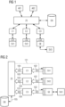
- Figure 1 shows schematically and by way of example a structural and functional structure of the control system according to the invention for exemplary power supply components SV1, SV2, SV3 of at least one system.
- Power supply components SV1, SV2, SV3 e.g. electrical power supplies, switching power supplies, electrical fuses, measuring units, etc.
- Three exemplary power supply components SV1, SV2, SV3 are shown.
- a first and a second power supply component SV1, SV2 have an interface (eg RJ45 interface) for a direct connection to a communication network used, in particular Ethernet.
- a third power supply component SV3 for example, only has a serial interface for a point-to-point connection such as a USB interface or a binary interface for the transmission of quasi-static signals (e.g. non-time-critical or slightly time-critical queries of signal levels, measured values, etc.) on.
- a serial interface for a point-to-point connection such as a USB interface or a binary interface for the transmission of quasi-static signals (e.g. non-time-critical or slightly time-critical queries of signal levels, measured values, etc.) on.
- the inventive control system shown as an example includes a central server unit ZS, to which a database DB is assigned.
- Specific data and/or parameters of the respective power supply components SV1, SV2, SV3 e.g. device information, device type, address data, configuration parameters, version data of the device firmware, etc.
- the central server unit ZS and the associated database can be implemented, for example, on a computing unit (e.g. PC, laptop, etc.) or a distributed computer system.
- the central server unit ZS and/or the database DB can also be made available using so-called cloud computing, for example via the Internet or a company network.
- client units C1, C2, C3 are provided, which are set up for communication with or for transmitting the specific data and/or parameters from and to the central server unit ZS as well as from and to the respective power supply components SV1, SV2, SV3.
- a separate client unit C1, C2, C3 can be generated for each power supply component SV1, SV2, SV3 that is connected and identified via the communication network used (e.g. Ethernet).
- a first client unit C1 is generated for the first power supply unit SV1, a second client unit C2 for the second power supply unit SV2 and a third client unit C3 for the third power supply unit SV3.
- client units C1, C2, C3 For generating the client units C1, C2, C3, template units - so-called templates - are provided, to which at least part of the respective data structure and the functional design of the respective client unit C1, C2, C3 is already specified.
- the client units C1, C2, C3 can, for example, run on the same computing unit or on a different computing unit as the central server unit ZS. Furthermore, the client units C1, C2, C3 can also be provided using so-called cloud computing.
- control system includes local server units LS1, LS2, LS3, which are permanently assigned to the respective power supply components SV1, SV2, SV3.
- a first local Server unit LS1 of the first power supply component SV1 communicates with the first client unit C1 via the communication network used.
- a second local server unit LS2 of the second power supply component SV2 communicates with the second client unit C2 via the communication network.
- a so-called OPC UA interface can be used for communication or data transmission between the respective local server units LS1, LS2 and the respective client unit.
- a gateway unit GE is provided for connecting the third power supply component SV3, which, for example, only has a serial interface for a point-to-point connection (e.g. USB interface, binary interface, etc.) for connection to the communication network.
- the gateway unit GE is assigned a third local server unit LS3, which communicates with the third client unit C3.
- the third client unit C3 thus communicates with the third power supply component SV3 via the gateway unit GE.
- a so-called OPC-UA interface can be used again for communication or data transmission between the third client unit C3 and the third local server unit LS3, which is assigned to the gateway unit GE.
- At least one input/output unit AE1, AE2 can be connected, for example via a communication network (eg Internet, Ethernet, wireless communication network or radio network, etc.).
- a communication network eg Internet, Ethernet, wireless communication network or radio network, etc.
- two input/output units AE1, AE2 are provided, for example.
- Specific data and/or parameters for the respective power supply components SV1, SV2, SV3 can be input, output and/or changed via the input/output units and can be accessed for monitoring purposes.
- the input/output units AE1, AE2 are connected using an application, in particular a web application, from which a communication connection can be established, for example via the Internet, to the central server unit ZS and from which a client application to the central server unit ZS is formed.
- an application in particular a web application, from which a communication connection can be established, for example via the Internet
- the central server unit ZS and from which a client application to the central server unit ZS is formed.
- the respective displayed view can be generated dynamically based on the specific data and/or parameters stored for the respective power supply components SV1, SV2, SV3 in the database DB, which is assigned to the central server unit ZS.
- OPC UA methods and the Hypertext Transfer Protocol Secure (https) communication protocol can be used.
- authentication is also provided, for example by means of a valid user name and a password.
- scope of the displayed data and/or parameters as well as permissible modification and configuration options for power supply components SV1, SV2, SV3 can be specified by differently defined user roles.
- User-specific data e.g. user name, password, etc.
- defined user roles can, for example, ideally be stored encrypted in a local user directory in the database DB assigned to the central server unit ZS.
- the input, output or display and/or change of specific data and/or parameters of the respective power supply components SV1, SV2, SV3 via the respective input/output units AE1, AE2 is in an online mode or on-line and in an off-line mode or off-line.
- the online mode there is an active communication connection between the respective client unit C1, C2, C3 and thus the central server unit ZS and the local server units LS1, LS2, LS3, which are assigned to the power supply components SV1, SV2, SV3.
- data/parameters can be queried directly from a power supply component SV1, SV2, SV3 and displayed on the input/output unit AE1, AE2 or data and/or parameter changes can be sent to the power supply component SV1, SV2, SV3 directly via central Server unit ZS, client unit C1, C2, C3 and local server unit LS1, LS2, LS3 are transmitted.
- the off-line mode there is no communication connection to the respective power supply components SV1, SV2, SV3 or to the respective associated local server units LS1, LS2, LS3.
- Ie a data and/or parameter transfer for an output, input or change of specific data and/or parameters of the power supply components SV1, SV2, SV3 to the input/output unit AE1, AE2 is carried out by the central server unit ZS on the basis of stored data and /or parameters in the assigned database DB.
- the control system according to the invention is again shown schematically and by way of example, with three exemplary power supply components SV1, SV2, SV3 being monitored and controlled by the control system.
- the first and second power supply components SV1, SV2 can be connected directly to the communication network, for example, while the third power supply component SV3 is connected via the gateway unit GE.
- an identification call is sent out by the control system or by the central server unit ZS during a start process 101.
- the power supply components SV1, SV2, SV3 connected to the communication network are addressed by the control system using the identification call.
- the identification call for example in the form of a so-called multicast - the so-called Discovery and Configuration Protocol or DCP for short is used.
- response messages with unique identification data ID1, ID2, ID3 of the respective power supply components SV1, SV2, SV3 are sent back by the respective local server unit LS1, LS2, LS3, which are permanently assigned to the respective power supply components SV1, SV2, SV3.
- the response message with the unique identification data ID3 of the third power supply component SV3 is created by the gateway unit GE based on data from the third power supply component SV3 and sent.
- the unique identification data ID1, ID2, ID3 can, for example, contain at least one unique identifier for the respective power supply component SV1, SV2 or, in the case of indirectly connected power supply components SV3, for the gateway unit GE (e.g. MAC address), a device name and/or identifier IP address, etc. include.
- a client unit C1, C2, C3 is generated in a next generation process 103 for each identified power supply component SV1, SV2, SV3.
- the respective client unit C1, C2, C3 takes over the communication with the respective local server unit LS1, LS2, LS3 of the respective power supply component SV1, SV2 or the gateway unit GE for communication with the third power supply component SV3.
- template units or so-called templates are used to create the client units C1, C2, C3. These template units, for example, already have a basic structure for the client unit C1, C2, C3, which is generated for communication with the respective power supply component SV1, SV2, SV3.
- the client units C1, C2, C3 After the client units C1, C2, C3 have been created, there is a communication connection to the local server units LS1, LS2, LS3, which are assigned to the power supply components SV1, SV2, SV3, and the client units C1, C2, C3.
- the respective power supply components SV1, SV2, SV3 are therefore referred to as “on-line” and can be marked accordingly (e.g. by means of a lit or flashing LED).
- an alarm can be sent.
- an OPC UA interface is used to exchange data and/or parameters.
- the unique identification data ID1, ID2, ID3 of the respective power supply components SV1, SV2, SV3 are transmitted from the client units C1, C2, C3 to the central server unit ZS.
- this data ID1, ID2, ID3 is then stored in the database DB, which is assigned to the central server unit ZS.
- the power supply components SV1, SV2, SV3, which are connected directly and indirectly (ie via the gateway unit GE) via the communication network (e.g. Ethernet, radio network, etc.), are now known to the control system and can be used as an example in the Figures 3 and 4 can be controlled and monitored.
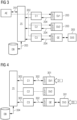
- FIG. 3 shows again schematically and by way of example the control system according to the invention, which now has existing communication connections to the three exemplary power supply components SV1, SV2, SV3.
- the power supply components SV1, SV2, SV3 are therefore referred to as “on-line”.
- Access to the central server unit ZS is established for a display and/or change process 201 via an input/output unit AE.
- a client application e.g. external OPC UA client, web application, etc.
- a corresponding authentication is required for the display and/or change process 201, for example using a user name and password. Then the power supply components SV1, SV2, SV3 marked as “on-line” are displayed on the input/output unit AE.
- power supply components SV1, SV2, SV3 can be selected in order to display and/or change the associated specific data and/or parameters on the input/output unit AE, wherein the displayed data and/or parameters of the central server unit ZS and the associated database DB are delivered.
- the changed specific data and/or parameters are forwarded first to the central server unit ZS and then to the respective client units C1, C2, C3 in a write process 202.
- the changed data and/or parameters of the respective power supply components SV1, SV2, SV3 are then transmitted from the respective client units C1, C2, C3 to the respective local server units LS1, LS2, LS3.
- changed data/parameters for the third power supply component SV3 are transmitted to the local server unit LS3 of the gateway unit GE, from which the changed data/parameters are forwarded to the third power supply component SV3 via the point-to-point connection (e.g. USB interface, binary interface, etc.) is adopted.
- point-to-point connection e.g. USB interface, binary interface, etc.
- the changed data/parameters are saved by the respective power supply components SV1, SV2, SV3.
- a corresponding message is sent from the respective local server unit LS1, LS2, LS3 to the respective client unit C1, C2, C3 during a feedback process 204.
- Only after receipt of the corresponding message are the changed data/parameters saved by the respective client unit C1, C2, C3 in a storage process 205 in the database DB assigned to the central server unit ZS.
- Figure 4 also shows schematically and by way of example the control system according to the invention, which has existing communication connections to the three exemplary power supply components SV1, SV2, SV3.
- local changes D1, D3 of the specific data and/or parameters are made in a change process 301 in the first and third power supply components SV1, SV3 (for example manually or by means of an input/output unit connected locally to the power supply component SV1, SV3).
- the first power supply component SV1 sends the locally changed data and/or parameters D1 to the first client unit by means of the first local server unit LS1.
- the third power supply component SV3 is connected to the communications network, for example, via the gateway unit GE. Therefore, for example, local changes D3 of data/parameters during the reporting process 302 are forwarded to the respective client unit C3 via the gateway unit GE or via the local server unit LS3 of the gateway unit.
- the respective local server unit LS1, LS3 can send a notification to the respective client unit C1, C3, for example as information about a local change D1, D3 of specific data and / or parameters.
- From the respective client unit C1, C3 are forwarded to the central server unit ZS in a forwarding process 303 and stored in a storage process 304 in the database DB assigned to the central server unit ZS.
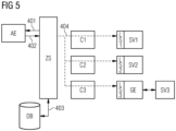
- FIG. 5 which also shows the control system according to the invention schematically and by way of example, an embodiment variant without an existing communication connection with the power supply components SV1, SV2, SV3 is shown as an example.
- the control system is operated off-line. Off-line operation can occur, for example, during a planning phase or a conversion phase of a system, during which, for example, there are no communication connections to all or individual power supply components SV1, SV2, SV3.
- template units or structures of various power supply components SV1, SV2, SV3 can be loaded in advance into the central server unit ZS or the associated database DB. From these template units or structures, for example, data types, structures, etc.
- the power supply components SV1, SV2, SV3 are thus made available off-line based on the template units or structures on the central server unit.
- a display and/or change process 401 the power supply components SV1, SV2, SV3 available off-line can then be displayed and changed on an input/output unit AE, for example for so-called off-line engineering.
- a write process 402 entered changes to the power supply components SV1, SV2, SV3 are then transferred to the central server unit ZS and stored in a save process 403 in the database DB assigned to the central server unit ZS.
- configurations of power supply units SV1, SV2, SV3 for new systems and/or conversions of systems or, for example, version changes of the so-called firmware of power supply components, etc. can be prepared and checked for errors.
- the saved changes can be transferred to the respective local server units LS1, LS2, LS3 with a transfer process 404.
- the changes can then be saved on the power supply components SV1, SV2, SV3 and therefore available there.
- several power supply components SV1, SV2, SV3 of a system can ideally be configured relatively quickly.
Description
Die gegenständliche Erfindung betrifft ein Steuerungssystem für Stromversorgungskomponenten, wie z.B. elektrische Stromversorgungen, elektrische Sicherungen, Messeinheiten, etc. von zumindest einer Anlage, von welchen eine Energieversorgung von Steuer- und/oder Computereinheiten der zumindest einen Anlage überwacht und gesteuert wird. Weiterhin betrifft die vorliegende Erfindung auch ein zugehöriges Verfahren zur Inbetriebnahme, Steuerung und Überwachung von Stromkomponenten der zumindest einen Anlage mit dem erfindungsgemäßen Steuerungssystem.The present invention relates to a control system for power supply components, such as electrical power supplies, electrical fuses, measuring units, etc. of at least one system, from which an energy supply of control and/or computer units of the at least one system is monitored and controlled. Furthermore, the present invention also relates to an associated method for commissioning, controlling and monitoring power components of the at least one system with the control system according to the invention.
Als Automatisierungsanlage bzw. kurz Anlage wird allgemein eine ganz oder teilweise automatisierte, industrielle Anlage zur Fertigung von Produkten oder zur Steuerung von Prozessen bezeichnet. Für die Fertigung von Produkten bzw. zur Steuerung von Prozessen umfassen industrielle Anlagen üblicherweise Steuer- und/oder Computereinheiten wie z.B. so genannte Industrie-PCs und/oder intelligente elektronische, meist mikroprozessorbasierte Geräte (z.B. Steuergeräte, Schutzgeräte, Druck- und Temperaturmessumformer, Durchflussmesser, Stellantriebe, speicherprogrammierbare Steuerungen, etc.), von welchen anlageninterne bzw. anlagenspezifische Prozesse gesteuert, überwacht und/oder kontrolliert werden.An automation system, or system for short, is generally referred to as a fully or partially automated industrial system for manufacturing products or controlling processes. For the production of products or for controlling processes, industrial systems usually include control and/or computer units such as so-called industrial PCs and/or intelligent electronic, usually microprocessor-based devices (e.g. control devices, protection devices, pressure and temperature transmitters, flow meters, Actuators, programmable logic controllers, etc.), which control, monitor and/or control system-internal or system-specific processes.
Für die Energieversorgung der Steuer- und/oder Computereinheiten werden in einer Anlage Stromversorgungskomponenten eingesetzt. Unter Stromversorgungskomponenten werden dabei alle Komponenten in einem Strompfad wie z.B. elektrische Stromversorgungen und/oder Schaltnetzteile, elektrische Sicherungen, Stromspeicher (z.B. Akkumulator, Kondensator, supraleitende magnetischer Energiespeicher, etc.), Messeinheiten, etc. verstanden, welche die Versorgung der jeweiligen Steuer- und/oder Computereinheit mit Energie über diesen Strompfad überwachen, steuern und sicherstellen und damit für möglichst störungsfreie Abläufe in der Anlage sorgen. Daher werden bei Anwendungen in industriellen Anlagen an die Stromversorgungskomponenten besondere Anforderungen gestellt. So spielen beispielsweise eine flexible und einfache Konfigurierung und Inbetriebnahme eine wichtige Rolle. Vor allem bei der Konzeption/Konfiguration von neuen Anlagen sowie bei Umbauten bestehender Industrieanlagen ist eine zuverlässige Versorgung der jeweiligen Steuer-und/oder Computereinheiten mit Energie sicherzustellen, um einen möglichst störungsfreien Betrieb der jeweiligen Anlage zu ermöglichen. Daher wäre speziell für Stromversorgungskomponenten ein einfach handhabbares und flexibles Steuerungs- und Überwachungssystem wünschenswert.Power supply components are used in a system to supply energy to the control and/or computer units. Power supply components include all components in a current path such as electrical power supplies and/or switching power supplies, electrical fuses, Current storage (e.g. accumulator, capacitor, superconducting magnetic energy storage, etc.), measuring units, etc. are understood, which monitor, control and ensure the supply of energy to the respective control and/or computer unit via this current path and thus ensure that processes in the system are as trouble-free as possible Provide facility. Therefore, applications in industrial systems place special demands on the power supply components. For example, flexible and simple configuration and commissioning play an important role. Especially when designing/configuring new systems and converting existing industrial systems, a reliable supply of energy to the respective control and/or computer units must be ensured in order to enable the respective system to operate as smoothly as possible. Therefore, an easy-to-use and flexible control and monitoring system would be desirable, especially for power supply components.
Im Anlagenbereich werden heutzutage beispielsweise für eine Konfiguration von Automatisierungskomponenten (z.B. Steuereinheiten, speicherprogrammierbare Steuerung, Computereinheiten, Feldgeräte, etc.) einer Anlage softwarebasierte Engineering-Werkzeuge eingesetzt. Je nach Leistungsumfang gibt es softwarebasierte Anwendungen, welche stationär auf einem Personal Computer (PC) oder z.B. für ein verteiltes Arbeiten auf mehreren PCs installiert sind bzw. betrieben werden. Üblicherweise sind umfangärmere bzw. spezialisierte Anwendungen nur auf einem PC installiert. In jüngerer Zeit werden Varianten der softwarebasierten Engineering-Werkzeuge auch als Applikationen für mobile Endgeräte (z.B. Handheld, Tablet, Smartphone, etc.) verfügbar gemacht, wobei wegen des geringeren Speicherplatzes und der geringeren Rechnerleistung der mobilen Endgeräte der Leistungsumfang des jeweiligen Engineering-Werkzeugs eingeschränkt werden muss. Weiterhin gewinnen im Zuge des so genannten Cloud Computings, welches eine Bereitstellung von IT-Infrastruktur (z.B. Speicherplatz, Rechenleistung, Anwendungssoftware) als Dienstleistung über das Internet beschreibt, Anwendungen an Bedeutung, welche auf gegebenenfalls verteilten Rechnereinheiten (z.B. Servern) betrieben werden und deren Funktionsumfang einem Nutzer online bzw. über das Internet zur Verfügung gestellt wird.In the plant sector, software-based engineering tools are now used, for example, to configure automation components (e.g. control units, programmable logic controllers, computer units, field devices, etc.) of a plant. Depending on the scope of services, there are software-based applications that are installed or operated stationary on a personal computer (PC) or, for example, for distributed work on several PCs. Usually, less extensive or specialized applications are only installed on one PC. More recently, variants of the software-based engineering tools have also been made available as applications for mobile devices (e.g. handheld, tablet, smartphone, etc.), although the scope of the respective engineering tool is limited due to the smaller storage space and the lower computing power of the mobile devices must become. Furthermore, in the course of so-called cloud computing, which provides the provision of IT infrastructure (e.g. storage space, computing power, application software) as a service over the Internet describes applications of importance which are operated on possibly distributed computer units (e.g. servers) and whose range of functions is made available to a user online or via the Internet.
Bei der Entwicklung von softwarebasierten Anwendungen für Automatisierungskomponenten muss meist genau festgelegt werden, auf welchen Zielsystemen (z.B. stationäre und/oder verteilte Endgeräte, mobile Endgeräte, Cloud Computing) und vor allem auf welchen Betriebssystemen (z.B. Windows, Linux, OS X, Unix, etc.) die jeweilige Anwendung bzw. Applikation betrieben werden soll. Das weist den Nachteil auf, dass beispielsweise Anwendungen bzw. Applikationen mit identem Leistungsumfang nicht auf unterschiedlichen Plattformen betrieben bzw. für unterschiedliche Zielsysteme zur Verfügung gestellt werden können. D.h. die jeweilige Anwendung muss an das entsprechende Zielsystem und/oder Betriebssystem sowie entsprechend der zu administrierenden Automatisierungskomponente angepasst werden. Weiterhin ist z.B. bei einem Plattformwechsel oder Änderungen im Betriebssystem zumindest eine entsprechende Anpassung der jeweiligen Anwendung oder Applikation notwendig.When developing software-based applications for automation components, it is usually necessary to specify exactly which target systems (e.g. stationary and/or distributed devices, mobile devices, cloud computing) and, above all, which operating systems (e.g. Windows, Linux, OS X, Unix, etc .) the respective application or application should be operated. This has the disadvantage that, for example, applications with identical scope of services cannot be operated on different platforms or made available for different target systems. This means that the respective application must be adapted to the corresponding target system and/or operating system as well as the automation component to be administered. Furthermore, for example, in the event of a platform change or changes in the operating system, at least a corresponding adjustment of the respective application is necessary.
Aus der Automatisierungstechnik sind Konzepte wie z.B. Field Device Tool (FDT), durch welches eine Parametrierung von Feldgeräten unterschiedlicher Hersteller mit nur einer softwarebasierten Anwendung ermöglicht wird, oder Field Device Integration (FDI) bekannt, welche im Beitrag "FDI Device Integration - Best of Both Worlds" atp edition 6/2010, Seite 16 bis 19 beschrieben ist und mit welchem Feldgeräte in einer Automatisierungsanlage möglichst plattformunabhängig integrierbar sind. Die FDI-Technologie basiert auf einer Client-Server-Architektur, in welcher die Feldgeräte zentral mittels einer zentralen Recheneinheit - einem Server - verwaltet werden. Dabei ist auf diesem Server eine Konfiguration jedes Feldgeräts innerhalb einer Topologie der Anlage abgelegt. Für eine tatsächliche Konfiguration der Feldgeräte ist ein Konfigurationswerkzeug vorgesehen, welches dazu eingerichtet ist, die Konfiguration der Feldgeräte bzw. der FDI-Clients zu verwalten. Dabei werden Änderungen zuerst an den Server geschrieben und dann das jeweilige Feldgerät übertragen, wobei eine bestehende Kommunikationsverbindung zwischen Server und Feldgerät bzw. FDI-Client notwendig ist und gegebenenfalls eine relativ hohe Belastung des jeweiligen Feldgeräts durch die Datenübertragung anfallen kann. Weiterhin ist das FDI-Konzept vor allem auf Feldgeräte beschränkt.From automation technology, concepts such as Field Device Tool (FDT), which enables parameterization of field devices from different manufacturers with just one software-based application, or Field Device Integration (FDI), which are described in the article "FDI Device Integration - Best of Both Worlds" atp edition 6/2010, pages 16 to 19 and with which field devices can be integrated into an automation system as platform-independently as possible. The FDI technology is based on a client-server architecture in which the field devices are managed centrally using a central processing unit - a server. A configuration of each field device within a topology of the system is stored on this server. For the actual configuration of the field devices, a configuration tool is provided, which is set up to Manage the configuration of the field devices or the FDI clients. Changes are first written to the server and then transmitted to the respective field device, whereby an existing communication connection between the server and the field device or FDI client is necessary and, if necessary, a relatively high load on the respective field device may arise due to the data transmission. Furthermore, the FDI concept is primarily limited to field devices.
Weiterhin ist aus der Schrift
Für Stromversorgungskomponenten wie z.B. elektrische Stromversorgungen und/oder Schaltnetzteile, elektrische Sicherungen, Messeinheiten, etc. sind im Gegensatz zu Automatisierungskomponenten (z.B. Steuergeräte, speicherprogrammierbare Steuerungen, Feldgeräte, etc.) kaum entsprechende Anwendungen und Applikationen zur Konfiguration, Steuerung und Überwachung bekannt. Aus den Schriften
Bei industriellen Stromversorgungskomponenten spielt üblicherweise der Wirkungsgrad eine signifikante Rolle. Daher ist eine Auswahl an in den Stromversorgungskomponenten verbauten Rechen- und Kommunikationseinheiten (z.B. Prozessoren, Ein-/Ausgabebandbreite, etc.) sowie eine Bemessung der Speicherkapazität beschränkt. Weiterhin besteht für die Auswahl der genutzten, elektronischen Bauteile ein hoher Kostendruck. Daher werden die Ressourcen für Datenverarbeitung und Datenkommunikation bei Stromversorgungskomponenten üblicherweise auf die Kernaufgaben abgestimmt. Für weiterführende Kommunikationsaufgaben (z.B. Datenaustauch mit der Web-Browser-Anwendung, Zugriff auf den Webserver, etc.) werden in Stromversorgungskomponenten meist nur Reserveressourcen zur Verfügung gestellt.Efficiency usually plays a significant role in industrial power supply components. Therefore, the selection of computing and communication units installed in the power supply components (e.g. processors, input/output bandwidth, etc.) as well as the measurement of the storage capacity are limited. There is also high cost pressure when selecting the electronic components used. Therefore, the resources for data processing and data communication in power supply components are usually tailored to the core tasks. For further communication tasks (e.g. data exchange with the web browser application, access to the web server, etc.), power supply components usually only provide reserve resources.
Damit weisen die in den beiden Schriften
Dies kann zu einer starken kommunikationstechnischen Belastung in der Stromversorgungskomponente führen.This can lead to a heavy communication load in the power supply component.
Aus der
Die
Dabei werden für die Interaktion zwischen Client und Server OPC-UA-Serveraufrufe verwendet und logisch zusammenhängende OPC-UA-Serveraufrufe durch einen Client zu einer Serveraufruf-Menge zusammengefasst, wobei die einzelnen OPC-UA Serveraufruf der Serveraufruf-Menge voneinander unabhängig übertragen werde.OPC UA server calls are used for the interaction between client and server and logically related OPC UA server calls are combined by a client into a server call set, whereby the individual OPC UA server calls in the server call set are transmitted independently of each other.
Der Erfindung liegt daher die Aufgabe zugrunde, ein Steuerungssystem sowie ein zugehöriges Verfahren anzugeben, durch welche Stromversorgungskomponenten in industriellen Anlagen plattformunabhängig, flexibel und auf einfache sowie kostengünstige Weise konfigurierbar, steuerbar und überwachbar sind, und welche eine möglichst geringe Belastung durch Datenübertragung und Datenverarbeitung für die jeweiligen Stromversorgungskomponenten aufweisen.The invention is therefore based on the object of specifying a control system and an associated method through which power supply components in industrial systems can be configured, controlled and monitored in a platform-independent, flexible and simple and cost-effective manner, and which have the lowest possible burden due to data transmission and data processing for the have respective power supply components.
Diese Aufgabe wird durch Steuerungssystem sowie ein zugehöriges Verfahren der eingangs genannten Art mit den Merkmalen gemäß den unabhängigen Patentansprüchen gelöst. Vorteilhafte Ausführungsformen der vorliegenden Erfindung sind in den abhängigen Ansprüchen beschrieben.This task is solved by a control system and an associated method of the type mentioned at the beginning with the features according to the independent patent claims. Advantageous embodiments of the present invention are described in the dependent claims.
Erfindungsgemäß erfolgt die Lösung der Aufgabe durch ein Steuerungssystem für Stromversorgungskomponenten von zumindest einer Anlage, von welchen eine Energieversorgung von Steuer- und/oder Computereinheiten der zumindest einen Anlage überwacht und gesteuert und damit sichergestellt wird. Dieses Steuerungssystem umfasst eine zentrale Servereinheit, Clienteinheiten sowie lokale Servereinheiten. Der zentralen Servereinheit ist eine Datenbank zum Abspeichern spezifischer Daten und/oder Parameter der jeweiligen Stromversorgungskomponenten wie z.B. Geräteinformationen, Konfigurationsparameter, Versionsdaten, etc. zugeordnet. Die Clienteinheiten sind zur Kommunikation mit den Stromversorgungskomponenten bzw. mit den lokalen Servereinheiten und zur Übertragung der spezifischen Daten und/oder Parameter von und zu den Stromversorgungseinheiten eingerichtet. Dazu ist für jede über ein Kommunikationsnetz angeschlossene und identifizierte Stromversorgungskomponente eine eigene Clienteinheit generierbar. Die lokalen Servereinheiten sind den jeweiligen Stromversorgungskomponenten fest zugeordnet und für eine Kommunikation mit den jeweiligen Clienteinheiten eingerichtet.According to the invention, the problem is solved by a control system for power supply components of at least one system, from which an energy supply to control and/or computer units of the at least one system is monitored and controlled and thus ensured. This control system includes a central server unit, client units and local server units. A database for storing specific data and/or parameters of the respective power supply components such as device information, configuration parameters, version data, etc. is assigned to the central server unit. The client units are set up to communicate with the power supply components or with the local server units and to transmit the specific data and/or parameters from and to the power supply units. This requires each power supply component connected and identified via a communications network a separate client unit can be generated. The local server units are permanently assigned to the respective power supply components and set up for communication with the respective client units.
Der Hauptaspekt der erfindungsgemäß vorgeschlagenen Lösung besteht darin, dass durch eine entsprechende Kommunikations- und Datenverarbeitungsarchitektur des erfindungsgemäßen Steuerungssystems eine Belastung der Stromversorgungskomponenten durch Datenkommunikation und Datenverarbeitung möglichst gering gehalten wird. In der zentralen Servereinheit bzw. in der zugeordneten Datenbank ist ein Abbild der jeweiligen spezifischen Daten und/oder Parameter der in zumindest einer Anlage verwendeten Stromversorgungskomponenten realisiert, auf welches für Konfiguration, Administration, Steuerungs- und Überwachungszwecke weitgehend uneingeschränkt zugegriffen werden kann. Eine Datenübertragung bzw. Kommunikation mit den jeweiligen Stromversorgungskomponenten, welche mit dem Steuerungssystem über ein Kommunikationsnetz verbunden und identifiziert sind, wird mittels der jeweiligen für die jeweiligen Stromversorgungseinheiten generierten Clienteinheiten auf wenige notwendige Zugriffe eingeschränkt - insbesondere um die Daten und/oder Parameter zwischen lokalen Servereinheiten bzw. Stromversorgungskomponenten und der der zentralen Servereinheit zugeordneten Datenbank konsistent zu halten. Die zentrale Servereinheit mit der zugeordneten Datenbank weist damit die Wirkung eines "Datendrehkreuzes" auf, durch welches virtuelle Instanzen der jeweiligen Stromversorgungskomponenten dargestellt werden und die kommunikations- und datentechnische Belastung der einzelnen Stromversorgungskomponente erheblich reduziert wird.The main aspect of the solution proposed according to the invention is that a corresponding communication and data processing architecture of the control system according to the invention keeps the load on the power supply components due to data communication and data processing as low as possible. An image of the respective specific data and/or parameters of the power supply components used in at least one system is implemented in the central server unit or in the associated database, which can be accessed largely without restriction for configuration, administration, control and monitoring purposes. Data transmission or communication with the respective power supply components, which are connected and identified with the control system via a communication network, is limited to a few necessary accesses using the respective client units generated for the respective power supply units - in particular in order to transfer the data and/or parameters between local server units or .To keep power supply components and the database assigned to the central server unit consistent. The central server unit with the assigned database thus has the effect of a "data hub", through which virtual instances of the respective power supply components are represented and the communication and data technology load on the individual power supply components is significantly reduced.
Die Kombination aus zentraler Servereinheit, Clienteinheiten, welche für jede identifizierte Stromversorgungskomponente generierbar sind und von welchen die Kommunikation mit der jeweiligen Stromversorgungskomponente bzw. der jeweils fix zugeordneten lokalen Servereinheit übernehmen, und lokalen Servereinheiten, welche den Stromversorgungskomponenten fix zugeordnet sind, ermöglicht eine weitgehend plattform- und geräteunabhängige sowie flexible Ausgestaltung des Steuersystems. Das Steuersystem kann damit ohne funktionale Einschränkungen auf verschiedenen Hardwarearchitekturvarianten (z.B. stationäres PC-System, verteiltes Rechnersystem, Cloud Computing) ablaufen.The combination of central server unit, client units, which can be generated for each identified power supply component and from which the communication with the respective power supply component or the respectively permanently assigned local server unit, and local server units, which are fixed to the power supply components assigned, enables a largely platform- and device-independent and flexible design of the control system. The control system can therefore run on different hardware architecture variants (e.g. stationary PC system, distributed computer system, cloud computing) without functional restrictions.
Weiterhin wird durch die Kommunikations- und Datenverarbeitungsarchitektur des erfindungsgemäßen Steuerungssystems eine freiskalierbare Server-Client-Beziehung, idealerweise eine n-zu-m-Beziehung, ermöglicht. Durch den Einsatz der zentralen Servereinheit wird eine 1-zu-1-Beziehung zwischen generierbaren Clienteinheiten und Stromversorgungskomponenten bzw. den jeweils diesen fix zugeordneten Servereinheiten aufgelöst. Für Konfiguration, Administration, Steuerungs- und Überwachungszwecke wird auf die zentrale Servereinheit zugegriffen - z.B. mittels Client-Applikationen, deren Anzahl beispielsweise durch Konfiguration, Kapazität, etc. der zentralen Servereinheit vorgegeben sein kann und deren Anzahl damit unabhängig von der Anzahl der identifizierten und mittels dem erfindungsgemäßen Steuerungssystem gesteuerten und überwachten Stromversorgungskomponenten ist.Furthermore, the communication and data processing architecture of the control system according to the invention enables a freely scalable server-client relationship, ideally an n-to-m relationship. By using the central server unit, a 1-to-1 relationship is resolved between generatable client units and power supply components or the server units permanently assigned to them. The central server unit is accessed for configuration, administration, control and monitoring purposes - for example by means of client applications, the number of which can be predetermined, for example, by the configuration, capacity, etc. of the central server unit and the number of which is therefore independent of the number of identified and used the control system according to the invention is controlled and monitored power supply components.
Eine zweckmäßige Weiterbildung der Erfindung sieht vor, dass weiterhin eine zumindest eine Ein-/Ausgabeeinheit anbindbar ist. Über diese zumindest eine Ein-/Ausgabeeinheit sind die spezifischen Daten und/oder Parameter für die jeweiligen Stromversorgungskomponenten eingebbar, ausgebbar und/oder änderbar. Idealerweise erfolgt die Anbindung der zumindest einen Ein-/Ausgabeeinheit mittels einer Applikation, insbesondere Webapplikation. Eingabe, Ausgabe und/oder Änderung der spezifischen Daten und/oder Parameter für die jeweiligen Stromversorgungskomponenten sind mittels eines Webbrowser durchführbar, wobei in vorteilhafter Weise ein standardisierter Internet- oder Webbrowser als Benutzerschnittstelle für die zumindest eine Ein-/Ausgabeeinheit einsetzbar ist. Dadurch können beispielsweise ohne zusätzlichen Aufwand bzw. ohne Einschränkungen in der Funktion ein stationärer PC, stationäre PC-Systeme und mobile Endgeräte (z.B. Tablet-PC, Handheld, etc.) für die Ein-/Ausgabeeinheit bzw. als für eine Anzeige einer Benutzeroberfläche genutzt werden. Weiterhin ist eine Nutzung im Rahmen von so genannten Cloud Computing möglich, über welches beispielsweise die Ein-/Ausgabeeinheit bzw. die Anzeige der Benutzeroberfläche sowie ein Zugriff auf die Funktionalitäten des erfindungsgemäßen Steuerungssystems, insbesondere auf die zentrale Servereinheit, mittels Anwendung zur Verfügung gestellt werden.An expedient development of the invention provides that at least one input/output unit can also be connected. The specific data and/or parameters for the respective power supply components can be input, output and/or changed via this at least one input/output unit. Ideally, the at least one input/output unit is connected using an application, in particular a web application. Input, output and/or change of the specific data and/or parameters for the respective power supply components can be carried out using a web browser, with a standardized Internet or web browser advantageously being able to be used as a user interface for the at least one input/output unit. This means, for example, that a stationary PC can be installed without any additional effort or without any restrictions on its functionality PC systems and mobile devices (e.g. tablet PC, handheld, etc.) can be used for the input/output unit or to display a user interface. Furthermore, use is possible in the context of so-called cloud computing, via which, for example, the input/output unit or the display of the user interface as well as access to the functionalities of the control system according to the invention, in particular to the central server unit, are made available by means of an application.
Es ist vorteilhaft, wenn die Eingabe, die Ausgabe und/oder Änderungen von spezifischen Daten und/oder Parametern für die Stromversorgungskomponenten über die Ein-/Ausgabeeinheit online und off-line vornehmbar sind. Bei on-line ausgeführten Ein-/Ausgaben und/oder Änderungen von Daten und/oder Parametern mittels Ein-/Ausgabeeinheit besteht eine Kommunikationsverbindung zwischen der jeweiligen Stromversorgungskomponente bzw. der lokalen, der jeweiligen Stromversorgungskomponente fix zugeordneten Servereinheit und der jeweiligen Clienteinheit. Off-line bedeutet, dass bei den jeweiligen Ein-/Ausgaben und/oder Änderungen von Daten oder Parametern keine Kommunikationsverbindung zwischen Clienteinheit und jeweiliger Stromversorgungskomponente bzw. der zugeordneten lokalen Servereinheit existiert oder noch keine Clienteinheit für die entsprechende Stromversorgungskomponente generiert wurde. Bei einem Off-line-Betrieb wird über die Ein-/Ausgabeeinheit nur auf die zentrale Servereinheit bzw. die entsprechenden Daten/Parameter aus der zugeordneten Datenbank zugegriffen. Im Off-line-Betrieb können z.B. ohne Daten- und Kommunikationsbelastung von Stromversorgungskomponenten einer Anlage oder in einer Anlagenplanungsphase, in welcher z.B. die Typen der Stromversorgungskomponenten ausgewählt, aber die Stromversorgungskomponenten selbst physisch noch nicht vorhanden sind, beispielsweise Konfigurationen für Stromversorgungskomponenten einer Anlage geplant, vorbereitet, verifiziert, auf Fehler, Zulässigkeit und Inkonsistenzen überprüft und gegebenenfalls simuliert werden.It is advantageous if the input, output and/or changes of specific data and/or parameters for the power supply components can be carried out online and offline via the input/output unit. When inputs/outputs and/or changes to data and/or parameters are carried out online using an input/output unit, there is a communication connection between the respective power supply component or the local server unit permanently assigned to the respective power supply component and the respective client unit. Off-line means that for the respective inputs/outputs and/or changes to data or parameters, there is no communication connection between the client unit and the respective power supply component or the assigned local server unit or that no client unit has yet been generated for the corresponding power supply component. In offline operation, only the central server unit or the corresponding data/parameters from the assigned database are accessed via the input/output unit. In offline operation, for example, configurations for power supply components of a system can be planned and prepared without data and communication load on power supply components of a system or in a system planning phase in which, for example, the types of power supply components are selected but the power supply components themselves are not yet physically present , verified, checked for errors, admissibility and inconsistencies and, if necessary, simulated.
Es ist günstig, wenn für ein Generieren der jeweiligen Clienteinheiten Vorlageeinheiten, so genannte Templates, vorgesehen sind. Diese Vorlageeinheiten stellen eine Art "Gerüst" für die jeweiligen Clienteinheiten dar, wobei ein Teil der jeweiligen Datenstruktur und funktionalen Ausgestaltung bereits vorgegeben wird. Fehlende Anteile wie z.B. aktuelle und für die jeweils identifizierte Stromversorgungskomponente spezifische Daten, Parameter und Strukturen werden beim Generieren der Clienteinheit ergänzt. Dadurch kann die jeweilige Clienteinheit bei Identifikation einer Stromversorgungskomponente rasch dynamisch generiert werden und die Belastung der jeweiligen Stromversorgungskomponente durch Datenkommunikation, etc. gering gehalten.It is advantageous if template units, so-called templates, are provided for generating the respective client units. These template units represent a kind of “framework” for the respective client units, with part of the respective data structure and functional design already being specified. Missing parts such as current data, parameters and structures specific to the identified power supply component are added when the client unit is generated. As a result, the respective client unit can be dynamically generated quickly when a power supply component is identified and the load on the respective power supply component due to data communication, etc. can be kept low.
Eine zweckmäßige Ausgestaltung des erfindungsgemäßen Steuerungssystems sieht vor, dass weiterhin eine Gateway-Einheit - d.h. eine Vermittlungseinheit - vorgesehen ist, welcher eine lokale Servereinheit zugeordnet ist. Über die Gateway-Einheit sind Stromversorgungskomponenten mittels einer seriellen Schnittstelle für Punkt-zu-Punkt-Verbindungen wie z.B. USB-Schnittstelle, binärer Schnittstelle, etc. anbindbar. Für die Kommunikation mit der lokalen, der Gateway-Einheit fest zugeordneten Servereinheit ist eine Clienteinheit generierbar, von welcher damit mit der über die Gateway-Einheit angebundene Stromversorgungskomponente unter Nutzung der Gateway-Einheit kommuniziert wird. Damit können durch das erfindungsgemäße Steuerungssystem ohne großen Aufwand auch Stromversorgungskomponenten gesteuert und überwacht werden, welche beispielsweise keine geeignete Schnittstelle (z.B. RJ45-Schnittstelle) für eine direkte Anbindung an das genutzte Kommunikationsnetz (z.B. Ethernet) aufweisen, sondern nur eine serielle Schnittstelle für Punkt-zu-Punkt-Verbindungen. Als serielle Schnittstelle für Punkt-zu-Punkt-Verbindungen kann beispielsweise für eine schnelle Datenübertragung zwischen der Stromversorgungskomponente und der Gateway-Einheit eine USB-Schnittstelle genutzt werden. Bei einer Übertragung von quasistatischen (d.h. sich langsam ändernden digitalen) und nicht zeitkritischen Signalen kann eine Anbindung der Stromversorgungskomponente beispielsweise mittels einer binären Schnittstelle bzw. I/O-Schnittstelle erfolgen. Die Übertragung derartiger Signale wie z.B. von einfachen Messwerten, Signalständen, etc. kann z.B. mehrere Sekunden in Anspruch nehmen.An expedient embodiment of the control system according to the invention provides that a gateway unit - ie a switching unit - is also provided, to which a local server unit is assigned. Power supply components can be connected via the gateway unit using a serial interface for point-to-point connections such as USB interface, binary interface, etc. For communication with the local server unit permanently assigned to the gateway unit, a client unit can be generated, which communicates with the power supply component connected via the gateway unit using the gateway unit. This means that the control system according to the invention can also be used to control and monitor power supply components without much effort, which, for example, do not have a suitable interface (e.g. RJ45 interface) for a direct connection to the communication network used (e.g. Ethernet), but only a serial interface for point-to-point connection -Point connections. For example, a USB interface can be used as a serial interface for point-to-point connections for fast data transfer between the power supply component and the gateway unit. When transmitting quasi-static (ie slowly changing digital) and non-time-critical signals, a connection of the Power supply component, for example, using a binary interface or I / O interface. The transmission of such signals, such as simple measured values, signal levels, etc., can take several seconds.
Eine zweckmäßige Weiterbildung des erfindungsgemäßen Steuerungssystems sieht vor, dass die zentrale Servereinheit und/oder die der zentralen Servereinheit zugeordnete Datenbank und/oder die Clienteinheiten mittels so genanntem Cloud Computing bereitstellbar sind. Bei Cloud Computing wird IT-Infrastruktur wie z.B. Speicherplatz, Rechenleistung oder Anwendungen als Dienstleistung über das Internet zur Verfügung gestellt. Das bietet den Vorteil, dass beispielsweise die Funktionalitäten des erfindungsgemäßen Steuersystems über das Internet als Dienstleistung z.B. Anlagenbetreibern kostengünstig angeboten werden können oder z.B. von einem Anlagenbetreiber mittels einer so genannten privaten Cloud-Umgebung für z.B. mehrere Anlagen ortsunabhängig genutzt werden können.An expedient development of the control system according to the invention provides that the central server unit and/or the database assigned to the central server unit and/or the client units can be made available by means of so-called cloud computing. With cloud computing, IT infrastructure such as storage space, computing power or applications is made available as a service over the Internet. This offers the advantage that, for example, the functionalities of the control system according to the invention can be offered cost-effectively via the Internet as a service, for example to system operators, or can be used, for example, by a system operator using a so-called private cloud environment for, for example, several systems regardless of location.
Idealerweise ist die Kommunikation zwischen Clienteinheiten und den lokalen Servereinheiten, welche den Stromversorgungskomponenten fest zugeordnet sind, mittels einer sogenannten OPC-UA-Schnittstelle durchführbar. OPC Unified Architecture oder kurz OPC-UA ist ein industriell genutzter Machine-to-Machine-Kommunikationsstandard bzw. ein industrielles Machine-to-Machine-Kommunikationsprotokoll, welches die Fähigkeit aufweist, maschinen- bzw. gerätespezifische Daten und/oder Parameter (z.B. Regelgrößen, Messwerte, Parameterwerte, etc.) nicht nur zu transportieren, sondern auch maschinenlesbar zu beschreiben. Die Nutzung einer OPC-UA-Schnittstelle für die Kommunikation bietet die Vorteile eines offenen, hersteller- und geräteunabhängigen Standards, mit welchem unterschiedliche Stromversorgungskomponenten angebunden werden können. Weiterhin beinhaltet OPC-UA mit Authentifizierung und Autorisierung, Verschlüsselung und Datenintegrität durch Signieren entsprechende Sicherheit und Schutz vor Manipulationen bei der Datenübertragung zwischen den Clienteinheiten und den lokalen Servereinheiten bzw. Stromversorgungskomponenten.Ideally, communication between client units and the local server units, which are permanently assigned to the power supply components, can be carried out using a so-called OPC UA interface. OPC Unified Architecture or OPC-UA for short is an industrially used machine-to-machine communication standard or an industrial machine-to-machine communication protocol that has the ability to process machine- or device-specific data and/or parameters (e.g. controlled variables, Measured values, parameter values, etc.) not only to be transported, but also to be described in a machine-readable way. The use of an OPC UA interface for communication offers the advantages of an open, manufacturer- and device-independent standard with which different power supply components can be connected. Furthermore, OPC-UA includes appropriate security and protection against manipulation with authentication and authorization, encryption and data integrity through signing data transmission between the client units and the local server units or power supply components.
Weiterhin ist es vorteilhaft, wenn für einen Zugang zu den spezifischen Daten und/der Parametern bzw. für eine Abfrage der spezifischen Daten und/oder Parameter der Stromversorgungskomponenten eine Authentifizierung vorgesehen ist, wobei ein Umfang an angezeigten Daten und/oder zulässige Veränderungs- und Konfigurationsmöglichkeiten durch unterschiedliche Nutzerrollen definierbar sind. Damit wird der Zugang mittels der Ein-/Ausgabeeinheit bzw. der Zugriff auf die zentrale Servereinheit und die zugeordnete Datenbank vor unberechtigten Zugriffen und Manipulationen geschützt. Weiterhin können durch Definition unterschiedlicher Nutzerrollen unterschiedliche Sichten auf der Ein-/Ausgabeeinheit bzw. mittels parallel ablaufender Applikationen auf die Daten und/oder Parameter bzw. Konfigurationen derselben Stromversorgungskomponenten angeboten werden.Furthermore, it is advantageous if authentication is provided for access to the specific data and/or parameters or for querying the specific data and/or parameters of the power supply components, with a scope of displayed data and/or permissible change and configuration options can be defined by different user roles. This protects access via the input/output unit or access to the central server unit and the associated database from unauthorized access and manipulation. Furthermore, by defining different user roles, different views can be offered on the input/output unit or by means of applications running in parallel on the data and/or parameters or configurations of the same power supply components.
Die Lösung der angegebenen Aufgabe erfolgt weiterhin durch ein zugehöriges Verfahren zur Inbetriebnahme, Steuerung und Überwachung von Stromversorgungskomponenten zumindest einer Anlage. Von den Stromversorgungskomponenten wird eine Energieversorgung von Steuer- und/oder Computereinheiten der zumindest einen Anlage überwacht und gesteuert. Das erfindungsgemäße Verfahren wird vom erfindungsgemäßen Steuerungssystem durchgeführt bzw. läuft auf diesem ab und weist zumindest die folgenden Schritte auf:
- Ansprechen von Stromversorgungskomponenten mittels eines Identifikationsaufrufs, welche über ein Kommunikationsnetz mit dem erfindungsgemäßen Steuerungssystem verbunden sind;
- Zurücksenden einer Antwortnachricht mit eindeutigen Identifikationsdaten der jeweiligen Stromversorgungskomponente durch lokale Servereinheiten, welche den jeweiligen Stromversorgungskomponenten fest zugeordnet sind;
- Generieren einer Clienteinheit für jede identifizierte Stromversorgungskomponente, wobei von der jeweiligen Clienteinheit eine Kommunikation mit der lokalen, der jeweiligen Stromversorgungskomponenten zugeordneten Servereinheit durchgeführt wird; und
- Übertragen der eindeutigen Identifikationsdaten der jeweiligen Stromversorgungskomponente durch die jeweilige Clienteinheit an eine zentrale Servereinheit und Abspeichern der eindeutigen Identifikationsdaten als spezifische Daten und/oder Parameter der jeweiligen Stromversorgungskomponente in der der zentralen Servereinheit zugeordneten Datenbank.
- Addressing power supply components by means of an identification call, which are connected to the control system according to the invention via a communication network;
- Sending back a response message with unique identification data of the respective power supply component by local server units which are permanently assigned to the respective power supply components;
- Generating a client unit for each identified power supply component, with the respective client unit communicating with the local one Server unit assigned to power supply components is carried out; and
- Transmitting the unique identification data of the respective power supply component by the respective client unit to a central server unit and storing the unique identification data as specific data and / or parameters of the respective power supply component in the database assigned to the central server unit.
Der Hauptaspekt des erfindungsgemäßen Verfahrens besteht ebenfalls darin, dass durch den Verfahrensablauf einerseits eine Belastung der Stromversorgungskomponenten durch Datenkommunikation und Datenverarbeitung relativ gering gehalten wird. Andererseits wird ein Verfahren zur Verfügung gestellt, durch welches mit den zu den jeweils identifizierten Stromversorgungskomponenten generierten Clienteinheiten eine Verbindung zu der zentralen Servereinheit und der zugeordneten Datenbank aufgebaut wird. In der zentralen Servereinheit bzw. in der zugeordneten Datenbank wird ein Abbild der jeweiligen spezifischen Daten und/oder Parameter der in zumindest einer Anlage verwendeten Stromversorgungskomponenten realisiert, auf welches für Konfiguration, Administration, Steuerungs- und Überwachungszwecke weitgehend uneingeschränkt z.B. mittels Ausgabe-Anwendungen zugegriffen werden kann. D.h. durch das erfindungsmäßige Verfahren wird eine freiskalierbare Server-Client-Beziehung, idealerweise eine n-zu-m-Beziehung, ermöglicht, bei welcher parallel mehrere und gegebenfalls unterschiedliche Sichten auf dieselben Stromversorgungskomponenten möglich sind. Die zentrale Servereinheit mit der zugeordneten Datenbank fungiert dabei als eine Art "Datendrehkreuz", durch welches virtuelle Instanzen der jeweiligen Stromversorgungskomponenten dargestellt werden und die kommunikations- und datentechnische Belastung der einzelnen Stromversorgungskomponente erheblich reduziert wird.The main aspect of the method according to the invention is also that, on the one hand, the process sequence keeps the load on the power supply components due to data communication and data processing relatively low. On the other hand, a method is provided by which a connection to the central server unit and the associated database is established using the client units generated for the respective identified power supply components. In the central server unit or in the associated database, an image of the respective specific data and / or parameters of the power supply components used in at least one system is realized, which can be accessed largely unrestricted for configuration, administration, control and monitoring purposes, for example using output applications can. This means that the method according to the invention enables a freely scalable server-client relationship, ideally an n-to-m relationship, in which several and possibly different views of the same power supply components are possible in parallel. The central server unit with the assigned database acts as a kind of "data hub", through which virtual instances of the respective power supply components are represented and the communication and data technology load on the individual power supply components is significantly reduced.
Es ist vorteilhaft, wenn zum Generieren der Clienteinheit für eine jeweils identifizierte Stromversorgungskomponente eine Vorlageeinheit herangezogen wird. Um die jeweiligen Clienteinheiten für die identifizierten Stromversorgungskomponenten auf einfache und rasche Weise dynamisch generieren zu können, können z.B. für verschiedene häufige genutzte Typen von Stromversorgungskomponenten (z.B. unterbrechungsfreie Stromversorgung, etc.) spezielle Vorlageeinheiten als eine Art "Gerüst" genutzt werden. Dabei wird ein Teil der jeweiligen Datenstruktur und funktionalen Ausgestaltung bereits vorgegeben. Fehlende Anteile wie z.B. aktuelle und für die jeweils identifizierte Stromversorgungskomponente spezifische Daten, Parameter und Strukturen werden beim Generieren der Clienteinheit ergänzt und die Belastung der Stromversorgungskomponente durch Datenkommunikation, etc. gering gehalten.It is advantageous if one is used to generate the client unit for each identified power supply component Template unit is used. In order to be able to dynamically generate the respective client units for the identified power supply components in a simple and rapid manner, special template units can be used as a kind of "scaffolding" for various frequently used types of power supply components (e.g. uninterruptible power supply, etc.). Part of the respective data structure and functional design is already specified. Missing parts such as current data, parameters and structures specific to the identified power supply component are added when the client unit is generated and the load on the power supply component through data communication, etc. is kept low.
Weiterhin ist es günstig, wenn bei bestehender Kommunikationsverbindung zwischen der jeweiligen Clienteinheit und der lokalen, der jeweiligen Stromversorgungskomponente zugeordneten Servereinheit und nach entsprechender Authentifizierung spezifische Daten und/oder Parameter der jeweiligen Stromversorgungskomponente auf einer Ein-/Ausgabeeinheit ausgegeben werden. Bei entsprechender Nutzerrolle können dann die spezifischen Daten und/oder Parameter der jeweiligen Stromversorgungskomponente geändert werden. Die jeweils geänderten, spezifischen Daten und/oder Parameter werden dann über die zentrale Servereinheit und die jeweilige Clienteinheit an die lokale, der jeweiligen Stromversorgungskomponente zugeordnete Servereinheit weitergeleitet, um dort von der lokalen, der jeweiligen Stromversorgungskomponente zugeordneten Servereinheit verarbeitet und/oder lokal abgespeichert zu werden. Weiterhin werden die geänderten Daten und/oder Parameter - üblicherweise nach erfolgreicher Weiterleitung und Verarbeitung durch die jeweilige lokale Servereinheit - in der der zentralen Servereinheit zugeordneten Datenbank abgespeichert.Furthermore, it is advantageous if, with an existing communication connection between the respective client unit and the local server unit assigned to the respective power supply component and after appropriate authentication, specific data and/or parameters of the respective power supply component are output on an input/output unit. If the user role is appropriate, the specific data and/or parameters of the respective power supply component can then be changed. The respective changed, specific data and/or parameters are then forwarded via the central server unit and the respective client unit to the local server unit assigned to the respective power supply component in order to be processed and/or stored locally by the local server unit assigned to the respective power supply component . Furthermore, the changed data and/or parameters are stored in the database assigned to the central server unit - usually after successful forwarding and processing by the respective local server unit.
Bei einer zweckmäßigen Ausgestaltung des erfindungsgemäßen Verfahrens werden lokale Änderungen von spezifischen Daten und/oder Parametern der jeweiligen Stromversorgungskomponente - d.h. Änderungen, welche beispielsweise direkt an der Stromversorgungskomponente z.B. manuell oder mittels einer lokal angebundenen Anzeigeeinheit vorgenommen werden - bei einer bestehenden Kommunikationsverbindung zwischen der jeweiligen Clienteinheit und der lokalen, der jeweiligen Stromversorgungskomponente von der lokalen, der jeweiligen Stromversorgungskomponente zugeordneten Servereinheit an die jeweils zugehörige Clienteinheit gesendet. Die gesendeten spezifischen Daten und/oder Parameter werden dann nach Weiterleitung durch die jeweilige Clienteinheit in der der zentralen Servereinheit zugeordneten Datenbank abgespeichert. Auf diese Weise wird sehr einfach sichergestellt, dass die Datenhaltung in der Datenbank, welche der zentralen Servereinheit zugeordnet ist, keine Inkonsistenzen bzw. Abweichungen gegenüber den lokal in den Stromversorgungskomponenten gespeicherten Daten und/Parametern aufweist.In an expedient embodiment of the method according to the invention, local changes to specific data and/or parameters of the respective power supply component - ie changes that occur, for example, directly on the power supply component eg manually or by means of a locally connected display unit - in the case of an existing communication connection between the respective client unit and the local server unit assigned to the respective power supply component, sent to the respective associated client unit by the local server unit assigned to the respective power supply component. The specific data and/or parameters sent are then stored in the database assigned to the central server unit after forwarding by the respective client unit. In this way, it is very easily ensured that the data storage in the database, which is assigned to the central server unit, does not have any inconsistencies or deviations compared to the data and/parameters stored locally in the power supply components.
Idealerweise wird bei lokaler Änderung von spezifischen Daten und/oder Parametern einer Stromversorgungskomponente eine Benachrichtigung von der lokalen, der jeweiligen Stromversorgungskomponente zugeordneten Servereinheit an die jeweilige Clienteinheit gesendet. Damit ist der jeweiligen Clienteinheit sowie über die Clienteinheit der zentralen Servereinheit bekannt, dass bei einer Stromversorgungskomponente lokale Änderungen vorgenommen worden sind. Es kann beispielsweise eine Übertragung der Änderungen an die Clienteinheit bzw. an die zentrale Servereinheit entsprechend geplant werden, um eine Belastung durch Kommunikation und Datenübertragung für die jeweilige Stromversorgungskomponente möglichst gering zu halten.Ideally, when specific data and/or parameters of a power supply component are changed locally, a notification is sent from the local server unit assigned to the respective power supply component to the respective client unit. This means that the respective client unit and the central server unit know via the client unit that local changes have been made to a power supply component. For example, a transmission of the changes to the client unit or to the central server unit can be planned accordingly in order to keep the burden of communication and data transmission on the respective power supply component as low as possible.
Es ist von Vorteil, wenn bei bestehender Kommunikationsverbindung zwischen der jeweiligen Clienteinheit und der lokalen, der jeweiligen Stromversorgungskomponente zugeordneten Servereinheit die Stromversorgungskomponente als "on-line" kennzeichnet wird. Damit ist auf einfache Weise ersichtlich, welche Stromversorgungskomponenten über einen aktive Kommunikationsverbindung zur jeweiligen Clienteinheit und damit zur zentralen Servereinheit aufweisen.It is advantageous if the power supply component is identified as "on-line" when there is an existing communication connection between the respective client unit and the local server unit assigned to the respective power supply component. This makes it easy to see which power supply components have an active communication connection to the respective client unit and thus to the central server unit.
Es ist weiterhin günstig, wenn bei einer Unterbrechung der bestehenden Kommunikationsverbindung zwischen der jeweiligen Clienteinheit und der lokalen, der Stromversorgungskomponente zugeordneten Servereinheit ein Alarm ausgesendet wird. Damit wird auf einfache Weise eine Unterbrechung der Kommunikationsverbindung angezeigt.It is also advantageous if an alarm is sent out if the existing communication connection between the respective client unit and the local server unit assigned to the power supply component is interrupted. This easily indicates an interruption in the communication connection.
Eine weitere, zweckmäßige Ausgestaltung des erfindungsgemäßen Verfahrens sieht vor, dass ohne bestehende Kommunikationsverbindung zwischen lokalen, den jeweiligen Stromversorgungskomponenten zugeordneten Servereinheiten und den zugehörigen Clienteinheiten Änderungen der spezifischen Daten und/oder Parameter der Stromversorgungskomponenten, welche über die Ein-/Ausgabeeinheit vorgenommen werden, in der der zentralen Servereinheit zugeordneten Datenbank abgespeichert werden. Erst bei einer bestehenden Kommunikationsverbindung zwischen lokalen, den jeweiligen Stromversorgungskomponenten zugeordneten Servereinheiten und den jeweiligen Clienteinheiten werden die Änderung der Daten und/oder Parameter an die jeweiligen lokalen, den jeweiligen Stromversorgungskomponenten zugeordneten Servereinheiten übertragen. Damit können in einem Off-line-Betrieb beispielsweise Konfigurationen von Stromversorgungseinheiten für neue Anlagen und/oder Umbauten von Anlagen oder z.B. Versionsänderungen der so genannten Firmware von Stromversorgungskomponenten, etc. vorbereitet werden. Bei bestehender Kommunikationsverbindung werden diese Änderungen dann an die jeweiligen lokalen, den jeweiligen Stromversorgungskomponenten zugeordneten Servereinheiten übertragen. Eine jeweilige Belastung der jeweiligen Stromversorgungskomponente durch die Übertragung kann damit sehr einfach berücksichtigt werden.A further expedient embodiment of the method according to the invention provides that without an existing communication connection between local server units assigned to the respective power supply components and the associated client units, changes to the specific data and / or parameters of the power supply components, which are carried out via the input / output unit, in the stored in the database assigned to the central server unit. Only when there is an existing communication connection between local server units assigned to the respective power supply components and the respective client units are the changes to the data and/or parameters transmitted to the respective local server units assigned to the respective power supply components. This allows, for example, configurations of power supply units for new systems and/or conversions of systems or, for example, version changes of the so-called firmware of power supply components, etc. to be prepared in off-line operation. If there is an existing communication connection, these changes are then transmitted to the respective local server units assigned to the respective power supply components. A respective load on the respective power supply component due to the transmission can therefore be taken into account very easily.
Eine zweckmäßige Ausgestaltung des erfindungsgemäßen Verfahrens sieht vor, dass für die bestehende Kommunikationsverbindung zwischen den lokalen, den jeweiligen Stromversorgungskomponenten zugeordneten Servereinheiten und den zugehörigen Clienteinheiten eine so genannte OPC-UA-Schnittstelle für einen Datenaustausch eingesetzt wird. Durch den Einsatz einer OPC-UA-Schnittstelle für die Kommunikation zwischen Clienteinheiten und den lokalen, den jeweiligen Stromversorgungskomponenten zugeordneten Servereinheiten wird eine Kommunikation nach einem offenen, hersteller- und geräteunabhängigen Standard ermöglicht. Weiterhin bietet OPC-UA eine entsprechende Sicherheit für die Datenübertragung und einen gewissen Schutz vor Manipulation durch Authentifizierung und Autorisierung, Verschlüsselung und Datenintegrität durch Signieren z.B. mittels der spezifischen Firmware der jeweiligen Stromversorgungskomponente.An expedient embodiment of the method according to the invention provides that a so-called OPC UA interface is used for data exchange for the existing communication connection between the local server units assigned to the respective power supply components and the associated client units. By using one OPC UA interface for communication between client units and the local server units assigned to the respective power supply components enables communication according to an open, manufacturer- and device-independent standard. Furthermore, OPC-UA offers appropriate security for data transmission and a certain level of protection against manipulation through authentication and authorization, encryption and data integrity through signing, for example using the specific firmware of the respective power supply component.
Idealerweise wird für ein Versenden des Identifikationsaufrufs das so genannte Discovery and Configuration Protocol (DCP) verwendet. Das Discovery and Configuration Protocol oder kurz DCP ist eine Protokolldefinition innerhalb des Kontextes von PROFINET, einem offenen industriellen genutzten Ethernet-Standards, welcher für Automatisierung genutzt wird. Mittels DCP können daher auf einfache Weise mittels eines Kommunikationsnetzes (z.B. Ethernet) angebundene Stromversorgungskomponenten zumindest einer Automatisierungsanlage detektiert bzw. über einen vom erfindungsgemäßen Steuerungssystem gesendeten, so genannten Multicast ermittelt werden.Ideally, the so-called Discovery and Configuration Protocol (DCP) is used to send the identification call. The Discovery and Configuration Protocol or DCP for short is a protocol definition within the context of PROFINET, an open industrial Ethernet standard used for automation. By means of DCP, power supply components of at least one automation system connected to a communication network (e.g. Ethernet) can therefore be detected in a simple manner or determined via a so-called multicast sent by the control system according to the invention.
Die Erfindung wird nachfolgend in beispielhafter Weise anhand der beigefügten Figuren erläutert. Es zeigen dabei:
-
Figur 1 -
Figur 2 einen beispielshaften Ablauf des erfindungsgemäßen Verfahrens zur Inbetriebnahme, Steuerung und Überwachung von Stromversorgungskomponenten zumindest einer Anlage -
Figur 3 -
Figur 4 eine weitere, beispielshafte Variante des erfindungsgemäßen Verfahrens bei bestehender Kommunikationsverbindung mit den Stromversorgungskomponenten -
Figur 5 eine beispielshafte Variante des erfindungsgemäßen Verfahrens ohne bestehende Kommunikationsverbindung mit den Stromversorgungskomponenten
-
Figure 1 schematically an exemplary structural design of the control system according to the invention for power supply components -
Figure 2 an exemplary sequence of the method according to the invention for commissioning, controlling and monitoring power supply components of at least one system -
Figure 3 an exemplary variant of the method according to the invention with an existing communication connection to the power supply components -
Figure 4 a further, exemplary variant of the method according to the invention with an existing communication connection with the power supply components -
Figure 5 an exemplary variant of the method according to the invention without an existing communication connection with the power supply components
Das in
Weiterhin sind Clienteinheiten C1, C2, C3 vorgesehen, welche für eine Kommunikation mit bzw. zur Übertragung der spezifischen Daten und/oder Parameter von und zu der zentralen Servereinheit ZS sowie von und zu den jeweiligen Stromversorgungskomponenten SV1, SV2, SV3 eingerichtet sind. Dabei ist für jede über das genutzte Kommunikationsnetz (z.B. Ethernet) angebundene und identifizierte Stromversorgungskomponente SV1, SV2, SV3 eine eigene Clienteinheit C1, C2, C3 generierbar. So wird beispielsweise für die erste Stromversorgungseinheit SV1 eine erste Clienteinheit C1, für die zweite Stromversorgungseinheit SV2 einen zweite Clienteinheit C2 und für die dritte Stromversorgungseinheit SV3 eine dritte Clienteinheit C3 generiert. Für ein Generieren der Clienteinheiten C1, C2, C3 sind dabei Vorlageeinheiten - so genannte Templates - vorgesehen, welchen zumindest ein Teil der jeweiligen Datenstruktur und der funktionalen Ausgestaltung der jeweiligen Clienteinheit C1, C2, C3 bereits vorgegeben wird. Die Clienteinheiten C1, C2, C3 können beispielsweise auf derselben Recheneinheit oder auf einer anderen Recheneinheit wie die zentrale Servereinheit ZS ablaufen. Weiterhin sind auch die Clienteinheiten C1, C2, C3 mittels so genanntem Cloud Computing bereitstellbar.Furthermore, client units C1, C2, C3 are provided, which are set up for communication with or for transmitting the specific data and/or parameters from and to the central server unit ZS as well as from and to the respective power supply components SV1, SV2, SV3. A separate client unit C1, C2, C3 can be generated for each power supply component SV1, SV2, SV3 that is connected and identified via the communication network used (e.g. Ethernet). For example, a first client unit C1 is generated for the first power supply unit SV1, a second client unit C2 for the second power supply unit SV2 and a third client unit C3 for the third power supply unit SV3. For generating the client units C1, C2, C3, template units - so-called templates - are provided, to which at least part of the respective data structure and the functional design of the respective client unit C1, C2, C3 is already specified. The client units C1, C2, C3 can, for example, run on the same computing unit or on a different computing unit as the central server unit ZS. Furthermore, the client units C1, C2, C3 can also be provided using so-called cloud computing.
Weiterhin umfasst das erfindungsgemäße Steuerungssystem lokale Servereinheiten LS1, LS2, LS3, welche den jeweiligen Stromversorgungskomponenten SV1, SV2, SV3 fest zugeordnet sind. So weisen beispielsweise die erste und zweite Stromversorgungskomponente SV1, SV2, welche eine Schnittstelle zur direkten Anbindung an das genutzte Kommunikationsnetz (z.B. Ethernet) aufweisen, lokale Servereinheiten LS1, LS2 auf, welche z.B. direkt in/auf der Stromversorgungskomponente ablauffähig angebracht sind. Dabei wird von einer ersten lokalen Servereinheit LS1 der ersten Stromversorgungskomponente SV1 mit der ersten Clienteinheit C1 über das genutzte Kommunikationsnetz kommuniziert. Von einer zweiten lokalen Servereinheit LS2 der zweiten Stromversorgungskomponente SV2 wird mit der zweiten Clienteinheit C2 über das Kommunikationsnetz kommuniziert. Für die Kommunikation bzw. Datenübertragung zwischen den jeweiligen lokalen Servereinheiten LS1, LS2 und den jeweiligen Clienteinheit ist beispielsweise eine so genannte OPC-UA-Schnittstelle einsetzbar.Furthermore, the control system according to the invention includes local server units LS1, LS2, LS3, which are permanently assigned to the respective power supply components SV1, SV2, SV3. For example, the first and second power supply components SV1, SV2, which have an interface for direct connection to the communication network used (eg Ethernet), have local server units LS1, LS2, which are mounted, for example, directly in/on the power supply component so that they can run. This is done by a first local Server unit LS1 of the first power supply component SV1 communicates with the first client unit C1 via the communication network used. A second local server unit LS2 of the second power supply component SV2 communicates with the second client unit C2 via the communication network. For example, a so-called OPC UA interface can be used for communication or data transmission between the respective local server units LS1, LS2 and the respective client unit.
Für eine Anbindung der dritten Stromversorgungskomponente SV3, welche beispielsweise nur eine serielle Schnittstelle für eine Punkt-zu-Punkt-Verbindung (z.B. USB-Schnittstelle, binäre Schnittstelle, etc.) zur Anbindung an das Kommunikationsnetz aufweist, ist eine Gateway-Einheit GE vorgesehen. Der Gateway-Einheit GE ist eine dritte lokale Servereinheit LS3 zugeordnet, von welcher mit der dritten Clienteinheit C3 kommuniziert wird. Die dritte Clienteinheit C3 kommuniziert somit über die Gateway-Einheit GE mit der dritten Stromversorgungskomponente SV3. Für die Kommunikation bzw. Datenübertragung zwischen der dritten Clienteinheit C3 und der dritten lokalen Servereinheit LS3, welche der Gateway-Einheit GE zugeordnet ist, kann beispielweise wieder eine so genannte OPC-UA-Schnittstelle verwendet werden.A gateway unit GE is provided for connecting the third power supply component SV3, which, for example, only has a serial interface for a point-to-point connection (e.g. USB interface, binary interface, etc.) for connection to the communication network. The gateway unit GE is assigned a third local server unit LS3, which communicates with the third client unit C3. The third client unit C3 thus communicates with the third power supply component SV3 via the gateway unit GE. For example, a so-called OPC-UA interface can be used again for communication or data transmission between the third client unit C3 and the third local server unit LS3, which is assigned to the gateway unit GE.
Weiterhin ist zumindest eine Ein-/Ausgabeeinheit AE1, AE2 z.B. über ein Kommunikationsnetz (z.B. Internet, Ethernet, drahtloses Kommunikationsnetz bzw. Funknetz, etc.) anbindbar. In der in
Eine Anbindung der Ein-/Ausgabeeinheiten AE1, AE2 erfolgt mittels einer Applikation, insbesondere einer Webapplikation, von welcher eine Kommunikationsverbindung z.B. über das Internet zur zentralen Servereinheit ZS herstellbar ist und von welcher eine Client-Anwendung zur zentralen Servereinheit ZS gebildet wird. Für Eingabe, Ausgabe bzw. Anzeige und/oder Änderung von spezifischen Daten und/oder Parametern der jeweiligen Stromversorgungskomponente SV1, SV2, SV3 durch bzw. auf einer der Ein-/Ausgabeeinheiten AE1, AE2 wie z.B. einem stationären Desktop-PC, einem mobilen Endgerät (z.B. Tablet-PC, Handheld, Smartphone, etc.) ist ein standardisierter Internet- oder Webbrowser einsetzbar. Die jeweilige angezeigte Ansicht ist dynamisch generierbar auf Basis der für die jeweilige Stromversorgungskomponenten SV1, SV2, SV3 in der Datenbank DB abgelegten spezifischen Daten und/oder Parameter, welche der zentralen Servereinheit ZS zugeordnet ist. Für eine Handhabung des dynamischen Datenaustauschs zwischen zentraler Servereinheit ZS und dem Webbrowser auf der jeweiligen Ein-/Ausgabeeinheit AE1, AE2 können beispielsweise OPC-UA-Methoden und auf dem Kommunikationsprotokoll Hypertext Transfer Protocol Secure (https) verwendet werden.The input/output units AE1, AE2 are connected using an application, in particular a web application, from which a communication connection can be established, for example via the Internet, to the central server unit ZS and from which a client application to the central server unit ZS is formed. For input, output or display and/or change of specific data and/or parameters of the respective power supply component SV1, SV2, SV3 by or on one of the input/output units AE1, AE2 such as a stationary desktop PC, a mobile terminal (e.g. tablet PC, handheld, smartphone, etc.) a standardized Internet or web browser can be used. The respective displayed view can be generated dynamically based on the specific data and/or parameters stored for the respective power supply components SV1, SV2, SV3 in the database DB, which is assigned to the central server unit ZS. To handle the dynamic data exchange between the central server unit ZS and the web browser on the respective input/output unit AE1, AE2, for example, OPC UA methods and the Hypertext Transfer Protocol Secure (https) communication protocol can be used.
Für einen Zugang zu bzw. eine Abfrage und/oder Änderung der spezifischen Daten und/oder Parameter der Stromversorgungskomponenten SV1, SV2, SV3 über die Ein-/Ausgabeeinheiten AE1, AE2 ist weiterhin einen Authentifizierung z.B. mittels eines gültigen Nutzernamens und eines Passworts vorgesehen. Weiterhin sind ein Umfang der angezeigten Daten und/oder Parameter sowie zulässige Veränderungs- und Konfigurationsmöglichkeiten von Stromversorgungskomponenten SV1, SV2, SV3 durch unterschiedlich definierte Nutzerrollen vorgebbar. Benutzerspezifische Daten (z.B. Nutzername, Passwort, etc.) sowie definierte Nutzerrollen können z.B. idealerweise verschlüsselt in einem lokalen Nutzerverzeichnis in der der zentralen Servereinheit ZS zugeordneten Datenbank DB abgelegt sein.To access or query and/or change the specific data and/or parameters of the power supply components SV1, SV2, SV3 via the input/output units AE1, AE2, authentication is also provided, for example by means of a valid user name and a password. Furthermore, the scope of the displayed data and/or parameters as well as permissible modification and configuration options for power supply components SV1, SV2, SV3 can be specified by differently defined user roles. User-specific data (e.g. user name, password, etc.) as well as defined user roles can, for example, ideally be stored encrypted in a local user directory in the database DB assigned to the central server unit ZS.
Die Eingabe, die Ausgabe bzw. Anzeige und/oder Änderung von spezifischen Daten und/oder Parametern der jeweiligen Stromversorgungskomponenten SV1, SV2, SV3 über die jeweiligen Ein-/Ausgabeeinheiten AE1, AE2 ist in einem On-line-Modus bzw. on-line und in einem Off-line-Modus bzw. off-line vornehmbar. Beim On-line-Modus existiert eine aktive Kommunikationsverbindung zwischen der jeweiligen Clienteinheit C1, C2, C3 und damit der zentralen Servereinheit ZS und den lokalen Servereinheiten LS1, LS2, LS3, welche den Stromversorgungskomponenten SV1, SV2, SV3 zugeordnet sind. Beim Online-Modus können daher z.B. Daten/Parameter direkt von einer Stromversorgungskomponente SV1, SV2, SV3 abgefragt und auf der Ein-/Ausgabeeinheit AE1, AE2 angezeigt bzw. Daten- und/oder Parameteränderungen an die Stromversorgungskomponente SV1, SV2, SV3 direkt über zentrale Servereinheit ZS, Clienteinheit C1, C2, C3 sowie lokale Servereinheit LS1, LS2, LS3 übertragen werden. Im Off-line-Modus besteht keine Kommunikationsverbindung zu den jeweiligen Stromversorgungskomponenten SV1, SV2, SV3 bzw. zu den jeweiligen zugehörigen lokalen Servereinheiten LS1, LS2, LS3. D.h. ein Daten- und/oder Parametertransfer für eine Ausgabe, Eingabe oder Änderung von spezifischen Daten und/oder Parametern der Stromversorgungskomponenten SV1, SV2, SV3 an die Ein-/Ausgabeeinheit AE1, AE2 erfolgt durch die zentrale Servereinheit ZS auf Basis von abgespeicherten Daten und/oder Parametern in der zugeordneten Datenbank DB.The input, output or display and/or change of specific data and/or parameters of the respective power supply components SV1, SV2, SV3 via the respective input/output units AE1, AE2 is in an online mode or on-line and in an off-line mode or off-line. In the online mode, there is an active communication connection between the respective client unit C1, C2, C3 and thus the central server unit ZS and the local server units LS1, LS2, LS3, which are assigned to the power supply components SV1, SV2, SV3. In online mode, for example, data/parameters can be queried directly from a power supply component SV1, SV2, SV3 and displayed on the input/output unit AE1, AE2 or data and/or parameter changes can be sent to the power supply component SV1, SV2, SV3 directly via central Server unit ZS, client unit C1, C2, C3 and local server unit LS1, LS2, LS3 are transmitted. In the off-line mode, there is no communication connection to the respective power supply components SV1, SV2, SV3 or to the respective associated local server units LS1, LS2, LS3. Ie a data and/or parameter transfer for an output, input or change of specific data and/or parameters of the power supply components SV1, SV2, SV3 to the input/output unit AE1, AE2 is carried out by the central server unit ZS on the basis of stored data and /or parameters in the assigned database DB.
In
Bei einem Identifikationsvorgang 102 werden von der jeweiligen lokalen Servereinheit LS1, LS2, LS3, welche den jeweiligen Stromversorgungskomponenten SV1, SV2, SV3 fest zugeordnet sind, Antwortnachrichten mit eindeutigen Identifikationsdaten ID1, ID2, ID3 der jeweiligen Stromversorgungskomponenten SV1, SV2, SV3 zurückgesendet. Für Stromversorgungskomponenten wie der beispielhaften dritten Stromversorgungskomponente SV3, welche über eine Gateway-Einheit GE an das Kommunikationsnetz angebunden ist, wird die Antwortnachricht mit den eindeutigen Identifikationsdaten ID3 der dritten Stromversorgungskomponente SV3 von der Gateway-Einheit GE auf Basis von Daten der dritten Stromversorgungskomponente SV3 erstellt und versendet. Die eindeutigen Identifikationsdaten ID1, ID2, ID3 können beispielsweise zumindest eine eindeutige Kennung für die jeweilige Stromversorgungskomponente SV1, SV2 bzw. bei indirekt angebundenen Stromversorgungskomponenten SV3 für die Gateway-Einheit GE (z.B. MAC-Adresse), einen Gerätenamen und/oder -kennung, eine IP-Adresse, etc. umfassen.During an
Nach dem Identifikationsvorgang 102 wird in einem nächsten Generierungsvorgang 103 für jede identifizierte Stromversorgungskomponente SV1, SV2, SV3 eine Clienteinheit C1, C2, C3 generiert. Von der jeweiligen Clienteinheit C1, C2, C3 wird die Kommunikation mit der jeweiligen lokalen Servereinheit LS1, LS2, LS3 der jeweiligen Stromversorgungskomponente SV1, SV2 bzw. der Gateway-Einheit GE für eine Kommunikation mit der dritten Stromversorgungskomponente SV3 übernommen. Beim Generierungsvorgang 103 werden für das Erstellen der Clienteinheiten C1, C2, C3 beispielsweise Vorlageeinheiten bzw. so genannte Templates herangezogen. Diese Vorlageeinheiten weisen z.B. bereits eine Grundstruktur für die Clienteinheit C1, C2, C3 auf, die für die Kommunikation mit der jeweiligen Stromversorgungskomponente SV1, SV2, SV3 erzeugt wird.After the
Nach Erzeugen der Clienteinheiten C1, C2, C3 besteht eine Kommunikationsverbindung zu den lokalen Servereinheiten LS1, LS2, LS3, welche den Stromversorgungskomponenten SV1, SV2, SV3 zugeordnet sind, und den Clienteinheiten C1, C2, C3. Die jeweiligen Stromversorgungskomponenten SV1, SV2, SV3 werden daher als "on-line" bezeichnet und können entsprechend (z.B. mittels einer leuchtenden oder blinkenden LED) gekennzeichnet werden. In der Folge kann beispielsweise bei einer Unterbrechung der bestehenden Kommunikationsverbindung zwischen einer Clienteinheit C1, C2, C3 und einer lokalen Servereinheit LS1, LS2, LS3, welche den Stromversorgungskomponenten SV1, SV2, SV3 zugeordnet sind, ein Alarm ausgesendet werden. Für die bestehende Kommunikationsverbindung zwischen Clienteinheiten C1, C2, C3 und den lokalen Servereinheiten SV1, SV2, SV3 wird z.B. einen OPC-UA-Schnittstelle zum Austausch von Daten und/oder Parametern eingesetzt.After the client units C1, C2, C3 have been created, there is a communication connection to the local server units LS1, LS2, LS3, which are assigned to the power supply components SV1, SV2, SV3, and the client units C1, C2, C3. The respective power supply components SV1, SV2, SV3 are therefore referred to as “on-line” and can be marked accordingly (e.g. by means of a lit or flashing LED). As a result, for example, if the existing communication connection between a client unit C1, C2, C3 and a local server unit LS1, LS2, LS3, which are assigned to the power supply components SV1, SV2, SV3, is interrupted, an alarm can be sent. For the existing communication connection between client units C1, C2, C3 and the local server units SV1, SV2, SV3, for example, an OPC UA interface is used to exchange data and/or parameters.
In einem Übertragungsvorgang 104 werden die eindeutigen Identifikationsdaten ID1, ID2, ID3 der jeweiligen Stromversorgungskomponenten SV1, SV2, SV3 von den Clienteinheiten C1, C2, C3 an die zentrale Servereinheit ZS übertragen. In einem Speichervorgang 105 werden dieses Daten ID1, ID2, ID3 dann in der Datenbank DB abgelegt, welche der zentralen Servereinheit ZS zugeordnet ist. Die über das Kommunikationsnetz (z.B. Ethernet, Funknetz, etc.) direkt und indirekt (d.h. via Gateway-Einheit GE) angebundenen Stromversorgungskomponenten SV1, SV2, SV3 sind nun dem Steuerungssystem bekannt und können wie beispielhaft in den
Über eine Ein-/Ausgabeeinheit AE wird für einen Anzeige- und/oder Änderungsvorgang 201 ein Zugang zur zentralen Servereinheit ZS aufgebaut. Dazu wird beispielsweise auf einem stationären oder mobilen Endgerät eine Client-Anwendung (z.B. externer OPC-UA-Client, Webapplikation, etc.) verwendet. Für die Verbindung zur zentralen Servereinheit ZS und eine Anzeige und/oder Änderung der spezifischen Daten und/oder Parameter der als "on-line" gekennzeichneten Stromversorgungskomponenten SV1, SV2, SV3 wird für den Anzeige und/oder Änderungsvorgang 201 eine entsprechende Authentifizierung z.B. mittels Benutzername und Passwort durchgeführt. Dann werden die als "on-line" gekennzeichneten Stromversorgungskomponenten SV1, SV2, SV3 auf der Ein-/Ausgabeeinheit AE angezeigt. Entsprechend einer Nutzerrolle des jeweiligen Benutzers können Stromversorgungskomponenten SV1, SV2, SV3 ausgewählt werden, um die zugehörigen spezifischen Daten und/oder Parameter auf der Ein-/Ausgabeeinheit AE anzeigen zu lassen und/oder zu ändern, wobei die angezeigten Daten und/oder Parameter von der zentralen Servereinheit ZS und der zugeordneten Datenbank DB geliefert werden.Access to the central server unit ZS is established for a display and/or
Bei einer Daten- und/oder Parameteränderung über die Ein-Ausgabeeinheit AE werden in einem Schreibvorgang 202 die geänderten spezifischen Daten und/oder Parameter zuerst an die zentrale Servereinheit ZS und dann an die jeweiligen Clienteinheiten C1, C2, C3 weitergeleitet. Von den jeweiligen Clienteinheiten C1, C2, C3 werden dann die geänderten Daten und/oder Parameter der jeweiligen Stromversorgungskomponente SV1, SV2, SV3 an die jeweiligen lokalen Servereinheiten LS1, LS2, LS3 übertragen. D.h. von der ersten bzw. zweiten Clienteinheit C1, C2 werden z.B. geänderte Daten/Parameter für die erste bzw. zweite Stromversorgungskomponente SV1, SV2 übertragen. Von der dritten Clienteinheit C3 werden geänderte Daten/Parameter für die dritte Stromversorgungskomponente SV3 an die lokale Servereinheit LS3 der Gateway-Einheit GE übertragen, von welcher Weitervermittlung der geänderten Daten/Parameter an die dritte Stromversorgungskomponente SV3 über die Punkt-zu-Punktverbindung (z.B. USB-Schnittstelle, binäre Schnittstelle, etc.) übernommen wird.When data and/or parameters are changed via the input/output unit AE, the changed specific data and/or parameters are forwarded first to the central server unit ZS and then to the respective client units C1, C2, C3 in a
In einem Verarbeitungsvorgang 203 werden die geänderten Daten/Parameter von den jeweiligen Stromversorgungskomponenten SV1, SV2, SV3 gespeichert. Nach einer erfolgreichen Weiterleitung und Speicherung der geänderten Daten/Parameter auf den jeweiligen Stromversorgungskomponenten SV1, SV2, SV3 wird bei einem Rückmeldevorgang 204 eine entsprechende Nachricht von der jeweiligen lokalen Servereinheit LS1, LS2, LS3 an die jeweilige Clienteinheit C1, C2, C3 gesendet. Erst nach Erhalt der entsprechenden Nachricht werden die geänderten Daten/Parameter von der jeweiligen Clienteinheit C1, C2, C3 in einem Speichervorgang 205 in die der zentralen Servereinheit ZS zugeordnete Datenbank DB gespeichert. Damit werden die Daten und/oder Parameter der Stromversorgungskomponenten SV1, SV2, SV3 in der Datenbank DB konsistent mit den Daten und/oder Parametern gehalten, welche lokal auf den Stromversorgungseinheiten SV1, SV2, SV3 gespeichert sind. Inkonsistenzen in der Datenhaltung in der Datenbank DB durch Fehler beim Schreibvorgang 202 und/oder beim Verarbeitungsvorgang 203 werden damit vermieden.In a
Von der jeweiligen Clienteinheit C1, C3 werden in einem Weiterleitungsvorgang 303 an die zentrale Servereinheit ZS weitergeleitet und in einem Speichervorgang 304 in der der zentralen Servereinheit ZS zugeordneten Datenbank DB abgespeichert.From the respective client unit C1, C3 are forwarded to the central server unit ZS in a
In
In einem Anzeige- und/oder Änderungsvorgang 401 können dann beispielsweise für ein so genanntes Off-line-Engineering die off-line verfügbaren Stromversorgungskomponenten SV1, SV2, SV3 auf einer Ein-/Ausgabeeinheit AE angezeigt und geändert werden. In einem Schreibvorgang 402 werden dann eingegebene Änderungen der Stromversorgungskomponenten SV1, SV2, SV3 auf die zentrale Servereinheit ZS übertragen und in einem Speichervorgang 403 in der der zentralen Servereinheit ZS zugeordneten Datenbank DB abgespeichert. Im Off-line-Betrieb können beispielweise Konfigurationen von Stromversorgungseinheiten SV1, SV2, SV3 für neue Anlagen und/oder Umbauten von Anlagen oder z.B. Versionsänderungen der so genannten Firmware von Stromversorgungskomponenten, etc. vorbereitet und auf Fehler überprüft werden.In a display and/or
Ist eine Kommunikationsverbindung zwischen den jeweiligen Clienteinheiten C1, C2, C3 und den lokalen Servereinheiten LS1, LS2, LS3, welche den Stromversorgungskomponenten SV1, SV2, SV3 fest zugeordnet sind, aufgebaut bzw. sind die Stromversorgungskomponenten SV1, SV2, SV3 "on-line", so können mit einem Übertragungsvorgang 404 die gespeicherten Änderungen an die jeweiligen lokalen Servereinheiten LS1, LS2, LS3 übertragen werden. Die Änderungen können dann auf den Stromversorgungskomponenten SV1, SV2, SV3 gespeichert werden und damit dort verfügbar. Mit der in
Claims (19)
- Control system for power supply components (SV1, SV2, SV3) of at least one system and by which an energy supply of control and/or computer units of the at least one system is monitored and controlled, comprising:- a central server unit (ZS) with assigned database (DB) for storing specific data and/or parameters of the respective power supply components (SV1, SV2, SV3);characterised in that the central server unit (ZS) is designed to send an identification call to the power supply components, and that the control system comprises the following units:- client units (C1, C2, C3) for communication and for transmitting the specific data and/or parameters from and to the power supply components (SV1, SV2, SV3), wherein a separate client unit (C1, C2, C3) can be generated for each power supply component connected via a communication network and identified by means of the identification call;- local server units (LS1, LS2, LS3) for communication with the respective client units (C1, C2, C3), which are permanently assigned to the respective power supply components (SV1, SV2, SV3).
- Control system according to claim 1, characterised in that at least one input/output unit (AE1, AE2) can be additionally connected via which the specific data/parameters for the respective power supply components (SV1, SV2, SV3) can be input, output and/or changed.
- Control system according to claim 2, characterised in that an application, in particular a web application, can be used for connecting the at least one input/output unit (AE1, AE2) and the inputting, outputting and/or changing of specific data and/or parameters for the respective power supply component (SV1, SV2, SV3) can be carried out by means of a web browser.
- Control system according to claim 2 or 3, characterised in that the inputting, outputting and/or changing of specific data and/or parameters for the respective power supply components (SV1, SV2, SV3) can be carried out online and offline via the at least one input/output unit.
- Control system according to one of the preceding claims, characterised in that templates are provided for generating the respective client units (C1, C2, C3).
- Control system according to one of the preceding claims, characterised in that a gateway unit (GE) is additionally provided to which a local server unit (LS3) can be assigned and via which a power supply component (SV3) can be connected by means of a point-to-point connection, wherein a client unit (C3) for communicating with the local server unit (LS3) assigned to the gateway unit (GE) can be generated.
- Control system according to one of the preceding claims, characterised in that the central server unit (ZS) and/or the database (DB) assigned to the central server unit (ZS) and/or the client units (C1, C2, C3) can be provided by means of so-called cloud computing.
- Control system according to one of the preceding claims, characterised in that the communication between the client units (C1, C2, C3) and the local server units (LS1, LS2, Ls3) which are permanently assigned to the power supply components (SV1, SV2, SV3) can be carried out by means of a so-called OPC-UA interface.
- The control system according to one of the preceding claims, characterised in that authentication is provided for accessing and/or interrogating the specific data and/or parameters of the power supply components (SV1, SV2, SV3), wherein a range of displayed data and/or permissible change and configuration options can be defined by different user roles.
- Method for startup, control and monitoring of power supply components (SV1, SV2, SV3) of at least one system and by which an energy supply of control and/or computer units of the at least one system is monitored and controlled, comprising a control system according to one of claims 1 to 9, characterised in that:- power supply components (SV1, SV2, SV3) which are connected to the control system via a communication network are addressed by means of an identification call (101) ,- a response message with unique identification data (ID1, ID2, ID3) of the respective power supply component (SV1, SV2, SV3) is transmitted back (102) by local server units (LS1, LS2, LS3) which are permanently assigned to the respective power supply components (SV1, SV2, SV3),- a client unit (C1, C2, C3) for communication with the local server unit (LS1, LS2, LS3) assigned to the respective power supply components (SV1, SV2, SV3) is generated (103) for each identified power supply component (SV1, SV2, SV3), and- the unique identification data (ID1, ID2, ID3) of the respective power supply components (SV1, SV2, SV3) is transmitted (104) by the respective client unit (C1, C2, C3) to a central server unit (ZS) and stored (105) in a database (DB) assigned to the central server unit (ZS).
- Method according to claim 10, characterised in that a template is used (103) to generate the client unit (C1, C2, C3) for an identified power supply component (SV1, SV2, SV3) .
- Method according to one of claims 10 to 11, characterised in that in the case of an existing communication link between the respective client unit (C1, C2, C3) and local server unit (LS1, LS2, LS3) assigned to the respective power supply component (SV1, SV2, SV3), and after appropriate authentication, specific data and/or parameters of the respective power supply component are output on an input/output unit (AE1, AE2), that if the user role is appropriate, the specific data and/or parameters of the respective power supply component (SV1, SV2, SV3) are changed (201), that the changed specific data and/or parameters are forwarded (202) via the central server unit (ZS) and the respective client unit (C1, C2, C3) to the local server unit (LS1, LS2, LS3) assigned to the respective power supply component (SV1, SV2, SV3) and, after successful forwarding (203, 204), are stored (205) in the database (DB) assigned to the central server unit (ZS).
- Method according to one of claims 10 to 12, characterised in that in the case of an existing communication link between the respective client unit (C1, C2, C3) and the local server unit (LS1, LS2, LS3) assigned to the respective power supply component (SV1, SV2, SV3), local changes (301, D1, D3) of specific data and/or parameters of the respective power supply component (SV1, SV2, SV3) are transmitted (302) to the respective client unit (C1, C2, C3) by the local server unit (LS1, LS2, LS3) assigned to the respective power supply component (SV1, SV2, SV3), and that after forwarding by the respective client unit (C1, C3, 303) the transmitted specific data and/or parameters of the respective power supply component (SV1, SV2, SV3) are stored (304) in the database (DB) assigned to the central server unit (ZS).
- Method according to claim 13, characterised in that if specific data and/or parameters of a power supply component (SV1, SV2, SV3) are changed locally, a notification is sent (302) to the respective client unit (C1, C2, C3) by the local server unit (LS1, LS2, LS3) assigned to the respective power supply component (SV1, SV2, SV3).
- Method according to one of claims 10 to 14, characterised in that in the case of an existing communication link between the respective client unit (C1, C2, C3) and the local server unit (LS1, LS2, LS3) assigned to the respective power supply component (SV1, SV2, SV3), the power supply component (SV1, SV2, SV3) is indicated as "online".
- Method according to one of claims 10 to 15, characterised in that in the event of a break in the existing communication link between the respective client unit (C1, C2, C3) and the local server unit (LS1, LS2, LS3) assigned to the respective power supply component (SV1, SV2, SV3), an alarm is sent out.
- Method according to one of claims 10 to 11, characterised in that in the absence of an existing communication link between local server units (LS1, LS2, LS3) assigned to the respective power supply components (SV1, SV2, SV3) and the associated client units (C1, C2, C3), changes to the specific data and/or parameters of the power supply components (SV1, SV2, SV3) are carried out (401, 402) via the input/output unit (AE1, AE2) and stored (403) in the database (DB) assigned to the central server unit (ZS), and that the change is only transmitted (404) to the respective local server units (LS1, LS2, LS3) assigned to the respective power supply components (SV1, SV2, SV3) if a communication link exists between local server units (LS1, LS2, LS3) assigned to the respective power supply components (SV1, SV2, SV3) and the respective client units (C1, C2, C3).
- Method according to one of claims 10 to 17, characterised in that, for the existing communication link between the local server units (LS1, LS2, LS3) assigned to the respective power supply components (SV1, SV2, SV3) and the respective client units (C1, C2, C3), a so-called OPC-UA interface is used for data exchange.
- Method according to one of claims 10 to 18, characterised in that the so-called Discovery and Configuration Protocol (DCP) is used (101) for transmitting the identification call.
Priority Applications (3)
| Application Number | Priority Date | Filing Date | Title |
|---|---|---|---|
| EP18156846.0A EP3528064B1 (en) | 2018-02-15 | 2018-02-15 | Control system and associated method for commissioning, controlling and monitoring current supply components |
| US16/275,591 US20190250686A1 (en) | 2018-02-15 | 2019-02-14 | Control System and Associated Method for Startup, Control and Monitoring of Power Supply Components |
| CN201910116929.3A CN110161896B (en) | 2018-02-15 | 2019-02-15 | Control system for a power supply assembly and associated method for starting, controlling and monitoring a power supply assembly |
Applications Claiming Priority (1)
| Application Number | Priority Date | Filing Date | Title |
|---|---|---|---|
| EP18156846.0A EP3528064B1 (en) | 2018-02-15 | 2018-02-15 | Control system and associated method for commissioning, controlling and monitoring current supply components |
Publications (3)
| Publication Number | Publication Date |
|---|---|
| EP3528064A1 EP3528064A1 (en) | 2019-08-21 |
| EP3528064C0 EP3528064C0 (en) | 2023-12-06 |
| EP3528064B1 true EP3528064B1 (en) | 2023-12-06 |
Family
ID=61244382
Family Applications (1)
| Application Number | Title | Priority Date | Filing Date |
|---|---|---|---|
| EP18156846.0A Active EP3528064B1 (en) | 2018-02-15 | 2018-02-15 | Control system and associated method for commissioning, controlling and monitoring current supply components |
Country Status (3)
| Country | Link |
|---|---|
| US (1) | US20190250686A1 (en) |
| EP (1) | EP3528064B1 (en) |
| CN (1) | CN110161896B (en) |
Families Citing this family (3)
| Publication number | Priority date | Publication date | Assignee | Title |
|---|---|---|---|---|
| US11366451B2 (en) | 2019-09-24 | 2022-06-21 | Rockwell Automation Technologies, Inc. | System and method for providing access to electrical circuitry based on operational status |
| US11397419B2 (en) | 2019-09-24 | 2022-07-26 | Rockwell Automation Technologies, Inc. | Electrical status indication system |
| JP2023151976A (en) * | 2022-04-01 | 2023-10-16 | オムロン株式会社 | Server device, information model providing method, and information model providing program |
Family Cites Families (10)
| Publication number | Priority date | Publication date | Assignee | Title |
|---|---|---|---|---|
| DE102004021380A1 (en) * | 2004-04-30 | 2005-12-01 | Siemens Ag | Device for power supply |
| US8190274B2 (en) | 2007-04-15 | 2012-05-29 | Phoenix Contact Gmbh & Co. Kg | Method and control device for controlling an automating system |
| US8327169B2 (en) * | 2009-02-26 | 2012-12-04 | International Business Machines Corporation | Power management to maximize reduced power state for virtual machine platforms |
| US8959362B2 (en) * | 2012-04-30 | 2015-02-17 | General Electric Company | Systems and methods for controlling file execution for industrial control systems |
| WO2015169355A1 (en) * | 2014-05-07 | 2015-11-12 | Siemens Aktiengesellschaft | Method and device for consistent set operations of data-changing opc-ua calls |
| EP2961052A1 (en) * | 2014-06-25 | 2015-12-30 | Siemens Aktiengesellschaft | Switching power supply with web interface |
| EP2960730A1 (en) | 2014-06-25 | 2015-12-30 | Siemens Aktiengesellschaft | Method for configuring a switching power supply |
| EP2996307B1 (en) * | 2014-09-10 | 2019-11-27 | Siemens Aktiengesellschaft | Method for energy-optimised data transmission using opc ua protocol |
| CN107567604B (en) * | 2015-03-27 | 2020-01-03 | 布勒有限公司 | Method and system for process control of a device |
| EP3086233B1 (en) * | 2015-04-23 | 2020-05-06 | CODESYS Holding GmbH | Method and system for measuring a runtime by means of watchpoints |
-
2018
- 2018-02-15 EP EP18156846.0A patent/EP3528064B1/en active Active
-
2019
- 2019-02-14 US US16/275,591 patent/US20190250686A1/en active Pending
- 2019-02-15 CN CN201910116929.3A patent/CN110161896B/en active Active
Also Published As
| Publication number | Publication date |
|---|---|
| US20190250686A1 (en) | 2019-08-15 |
| CN110161896B (en) | 2023-01-03 |
| EP3528064A1 (en) | 2019-08-21 |
| EP3528064C0 (en) | 2023-12-06 |
| CN110161896A (en) | 2019-08-23 |
Similar Documents
| Publication | Publication Date | Title |
|---|---|---|
| DE102010029952B4 (en) | Method for integrating at least one field device in a network of automation technology | |
| EP1738236B1 (en) | Automation network comprising network components that produce status messages | |
| EP3627800B1 (en) | Publish/subscribe communication of machine control data | |
| EP3353610B2 (en) | Connection unit, monitoring system and method for operating an automation system | |
| DE102020124789A1 (en) | HYPERCONVERGENT ARCHITECTURE FOR INDUSTRIAL SYSTEM | |
| EP2131256B1 (en) | Determining datagram lengths | |
| EP3616365B1 (en) | Method for operating a field device | |
| DE112017002494T5 (en) | MULTIPROTOCOL FIELD DEVICE IN PROCESS CONTROL SYSTEMS | |
| EP3528064B1 (en) | Control system and associated method for commissioning, controlling and monitoring current supply components | |
| DE102020124501A1 (en) | EDGE GATEWAY SYSTEM WITH DATA TYPING FOR THE SECURE DELIVERY OF PROCESS PLANT DATA | |
| DE102020124555A1 (en) | EDGE GATEWAY SYSTEM WITH CONTEXT-BASED PROCESS PLANT KNOWLEDGE DATABASE | |
| EP1491025A1 (en) | Webserver comprising integrated automation functionality | |
| EP3637205A1 (en) | Image activation on an operator station client | |
| WO2017182201A1 (en) | Method for monitoring the state of a process automation installation | |
| WO2020200877A1 (en) | Generating and distributing configuration data structures for control systems | |
| DE102010040055B4 (en) | System for communication of several clients with several field devices in automation technology | |
| EP1653308B1 (en) | Method and apparatus for providing and storing information | |
| EP3861413B1 (en) | Method for establishing network communication by means of opc ua | |
| DE102020124820A1 (en) | SECURE EXTERNAL ACCESS TO PROCESS CONTROL DATA THROUGH A MOBILE DEVICE | |
| DE102015200568A1 (en) | Method for exchanging data in an automation system | |
| EP3616011B1 (en) | Arrangement and method for monitoring an automation technology system | |
| DE102011077787A1 (en) | System for accessing e.g. field device in process automation engineering, has software module for replacing actual active driver instance with newly activated driver instance that is initialized with configuration data of actual instance | |
| EP2063570B1 (en) | Control device | |
| WO2021093928A1 (en) | Method and apparatus for discovering subscribers using the opc ua pubsub protocol | |
| EP1431898A2 (en) | Automation system and method for operating such a system |
Legal Events
| Date | Code | Title | Description |
|---|---|---|---|
| PUAI | Public reference made under article 153(3) epc to a published international application that has entered the european phase |
Free format text: ORIGINAL CODE: 0009012 |
|
| STAA | Information on the status of an ep patent application or granted ep patent |
Free format text: STATUS: THE APPLICATION HAS BEEN PUBLISHED |
|
| AK | Designated contracting states |
Kind code of ref document: A1 Designated state(s): AL AT BE BG CH CY CZ DE DK EE ES FI FR GB GR HR HU IE IS IT LI LT LU LV MC MK MT NL NO PL PT RO RS SE SI SK SM TR |
|
| AX | Request for extension of the european patent |
Extension state: BA ME |
|
| STAA | Information on the status of an ep patent application or granted ep patent |
Free format text: STATUS: REQUEST FOR EXAMINATION WAS MADE |
|
| 17P | Request for examination filed |
Effective date: 20200205 |
|
| RBV | Designated contracting states (corrected) |
Designated state(s): AL AT BE BG CH CY CZ DE DK EE ES FI FR GB GR HR HU IE IS IT LI LT LU LV MC MK MT NL NO PL PT RO RS SE SI SK SM TR |
|
| STAA | Information on the status of an ep patent application or granted ep patent |
Free format text: STATUS: EXAMINATION IS IN PROGRESS |
|
| 17Q | First examination report despatched |
Effective date: 20220321 |
|
| GRAP | Despatch of communication of intention to grant a patent |
Free format text: ORIGINAL CODE: EPIDOSNIGR1 |
|
| STAA | Information on the status of an ep patent application or granted ep patent |
Free format text: STATUS: GRANT OF PATENT IS INTENDED |
|
| RIC1 | Information provided on ipc code assigned before grant |
Ipc: G05B 19/418 20060101ALN20230614BHEP Ipc: G06F 1/26 20060101ALI20230614BHEP Ipc: H04L 67/12 20220101ALI20230614BHEP Ipc: G05B 19/042 20060101AFI20230614BHEP |
|
| RIC1 | Information provided on ipc code assigned before grant |
Ipc: G05B 19/418 20060101ALN20230705BHEP Ipc: G06F 1/26 20060101ALI20230705BHEP Ipc: H04L 67/12 20220101ALI20230705BHEP Ipc: G05B 19/042 20060101AFI20230705BHEP |
|
| INTG | Intention to grant announced |
Effective date: 20230718 |
|
| GRAS | Grant fee paid |
Free format text: ORIGINAL CODE: EPIDOSNIGR3 |
|
| GRAA | (expected) grant |
Free format text: ORIGINAL CODE: 0009210 |
|
| STAA | Information on the status of an ep patent application or granted ep patent |
Free format text: STATUS: THE PATENT HAS BEEN GRANTED |
|
| AK | Designated contracting states |
Kind code of ref document: B1 Designated state(s): AL AT BE BG CH CY CZ DE DK EE ES FI FR GB GR HR HU IE IS IT LI LT LU LV MC MK MT NL NO PL PT RO RS SE SI SK SM TR |
|
| REG | Reference to a national code |
Ref country code: GB Ref legal event code: FG4D Free format text: NOT ENGLISH |
|
| REG | Reference to a national code |
Ref country code: DE Ref legal event code: R096 Ref document number: 502018013733 Country of ref document: DE |
|
| REG | Reference to a national code |
Ref country code: CH Ref legal event code: EP |
|
| REG | Reference to a national code |
Ref country code: IE Ref legal event code: FG4D Free format text: LANGUAGE OF EP DOCUMENT: GERMAN |
|
| U01 | Request for unitary effect filed |
Effective date: 20231215 |
|
| U07 | Unitary effect registered |
Designated state(s): AT BE BG DE DK EE FI FR IT LT LU LV MT NL PT SE SI Effective date: 20231221 |
|
| U20 | Renewal fee paid [unitary effect] |
Year of fee payment: 7 Effective date: 20240219 |
|
| PG25 | Lapsed in a contracting state [announced via postgrant information from national office to epo] |
Ref country code: GR Free format text: LAPSE BECAUSE OF FAILURE TO SUBMIT A TRANSLATION OF THE DESCRIPTION OR TO PAY THE FEE WITHIN THE PRESCRIBED TIME-LIMIT Effective date: 20240307 |