EP3527975A1 - Ion-selective electrode with ion-selective membrane comprising a material with a dielectric constant of 10 or more and corresponding test piece - Google Patents
Ion-selective electrode with ion-selective membrane comprising a material with a dielectric constant of 10 or more and corresponding test piece Download PDFInfo
- Publication number
- EP3527975A1 EP3527975A1 EP19156983.9A EP19156983A EP3527975A1 EP 3527975 A1 EP3527975 A1 EP 3527975A1 EP 19156983 A EP19156983 A EP 19156983A EP 3527975 A1 EP3527975 A1 EP 3527975A1
- Authority
- EP
- European Patent Office
- Prior art keywords
- ion
- selective
- selective membrane
- dielectric material
- liquid
- Prior art date
- Legal status (The legal status is an assumption and is not a legal conclusion. Google has not performed a legal analysis and makes no representation as to the accuracy of the status listed.)
- Withdrawn
Links
- 239000012528 membrane Substances 0.000 title claims abstract description 203
- 238000012360 testing method Methods 0.000 title claims abstract description 68
- 239000000463 material Substances 0.000 title description 14
- 239000007788 liquid Substances 0.000 claims abstract description 186
- 239000003989 dielectric material Substances 0.000 claims abstract description 80
- 229920005989 resin Polymers 0.000 claims abstract description 39
- 239000011347 resin Substances 0.000 claims abstract description 39
- 239000011230 binding agent Substances 0.000 claims abstract description 32
- 239000002555 ionophore Substances 0.000 claims abstract description 31
- 230000000236 ionophoric effect Effects 0.000 claims abstract description 31
- 150000002500 ions Chemical class 0.000 claims description 291
- GWEVSGVZZGPLCZ-UHFFFAOYSA-N Titan oxide Chemical compound O=[Ti]=O GWEVSGVZZGPLCZ-UHFFFAOYSA-N 0.000 claims description 44
- 239000007787 solid Substances 0.000 claims description 36
- 229910001415 sodium ion Inorganic materials 0.000 claims description 25
- FKNQFGJONOIPTF-UHFFFAOYSA-N Sodium cation Chemical compound [Na+] FKNQFGJONOIPTF-UHFFFAOYSA-N 0.000 claims description 19
- 239000004408 titanium dioxide Substances 0.000 claims description 18
- NPYPAHLBTDXSSS-UHFFFAOYSA-N Potassium ion Chemical compound [K+] NPYPAHLBTDXSSS-UHFFFAOYSA-N 0.000 claims description 16
- 229910001414 potassium ion Inorganic materials 0.000 claims description 16
- 239000002245 particle Substances 0.000 claims description 15
- 150000001768 cations Chemical class 0.000 claims description 12
- 229910044991 metal oxide Inorganic materials 0.000 claims description 10
- 150000004706 metal oxides Chemical class 0.000 claims description 10
- RVTZCBVAJQQJTK-UHFFFAOYSA-N oxygen(2-);zirconium(4+) Chemical compound [O-2].[O-2].[Zr+4] RVTZCBVAJQQJTK-UHFFFAOYSA-N 0.000 claims description 8
- 229910001928 zirconium oxide Inorganic materials 0.000 claims description 8
- OGIDPMRJRNCKJF-UHFFFAOYSA-N titanium oxide Inorganic materials [Ti]=O OGIDPMRJRNCKJF-UHFFFAOYSA-N 0.000 claims description 7
- 229910002113 barium titanate Inorganic materials 0.000 claims description 6
- 229910000449 hafnium oxide Inorganic materials 0.000 claims description 6
- WIHZLLGSGQNAGK-UHFFFAOYSA-N hafnium(4+);oxygen(2-) Chemical compound [O-2].[O-2].[Hf+4] WIHZLLGSGQNAGK-UHFFFAOYSA-N 0.000 claims description 6
- JRPBQTZRNDNNOP-UHFFFAOYSA-N barium titanate Chemical compound [Ba+2].[Ba+2].[O-][Ti]([O-])([O-])[O-] JRPBQTZRNDNNOP-UHFFFAOYSA-N 0.000 claims description 5
- 239000003575 carbonaceous material Substances 0.000 claims description 5
- 239000000523 sample Substances 0.000 description 72
- 239000011342 resin composition Substances 0.000 description 47
- 238000000034 method Methods 0.000 description 46
- 238000005259 measurement Methods 0.000 description 32
- 239000004014 plasticizer Substances 0.000 description 26
- -1 tetralactone Substances 0.000 description 20
- 230000008569 process Effects 0.000 description 19
- 239000003795 chemical substances by application Substances 0.000 description 18
- 238000000576 coating method Methods 0.000 description 16
- 239000003792 electrolyte Substances 0.000 description 15
- 230000014759 maintenance of location Effects 0.000 description 15
- 230000015572 biosynthetic process Effects 0.000 description 13
- 239000011248 coating agent Substances 0.000 description 13
- 239000000243 solution Substances 0.000 description 13
- BZHJMEDXRYGGRV-UHFFFAOYSA-N Vinyl chloride Chemical compound ClC=C BZHJMEDXRYGGRV-UHFFFAOYSA-N 0.000 description 12
- 150000001450 anions Chemical class 0.000 description 12
- 230000000052 comparative effect Effects 0.000 description 11
- VEXZGXHMUGYJMC-UHFFFAOYSA-M Chloride anion Chemical compound [Cl-] VEXZGXHMUGYJMC-UHFFFAOYSA-M 0.000 description 10
- 238000004891 communication Methods 0.000 description 10
- 239000000758 substrate Substances 0.000 description 10
- WCUXLLCKKVVCTQ-UHFFFAOYSA-M Potassium chloride Chemical compound [Cl-].[K+] WCUXLLCKKVVCTQ-UHFFFAOYSA-M 0.000 description 8
- WYURNTSHIVDZCO-UHFFFAOYSA-N Tetrahydrofuran Chemical compound C1CCOC1 WYURNTSHIVDZCO-UHFFFAOYSA-N 0.000 description 8
- 229920001577 copolymer Polymers 0.000 description 8
- 229910052751 metal Inorganic materials 0.000 description 8
- 239000002184 metal Substances 0.000 description 8
- 239000004332 silver Substances 0.000 description 8
- 229910052709 silver Inorganic materials 0.000 description 8
- 229910021607 Silver chloride Inorganic materials 0.000 description 7
- HKZLPVFGJNLROG-UHFFFAOYSA-M silver monochloride Chemical compound [Cl-].[Ag+] HKZLPVFGJNLROG-UHFFFAOYSA-M 0.000 description 7
- CXVOIIMJZFREMM-UHFFFAOYSA-N 1-(2-nitrophenoxy)octane Chemical compound CCCCCCCCOC1=CC=CC=C1[N+]([O-])=O CXVOIIMJZFREMM-UHFFFAOYSA-N 0.000 description 6
- ZWEHNKRNPOVVGH-UHFFFAOYSA-N 2-Butanone Chemical compound CCC(C)=O ZWEHNKRNPOVVGH-UHFFFAOYSA-N 0.000 description 6
- BQCADISMDOOEFD-UHFFFAOYSA-N Silver Chemical compound [Ag] BQCADISMDOOEFD-UHFFFAOYSA-N 0.000 description 6
- 238000001035 drying Methods 0.000 description 6
- XKBGEWXEAPTVCK-UHFFFAOYSA-M methyltrioctylammonium chloride Chemical compound [Cl-].CCCCCCCC[N+](C)(CCCCCCCC)CCCCCCCC XKBGEWXEAPTVCK-UHFFFAOYSA-M 0.000 description 6
- 239000012466 permeate Substances 0.000 description 6
- 239000002904 solvent Substances 0.000 description 6
- XTXRWKRVRITETP-UHFFFAOYSA-N Vinyl acetate Chemical compound CC(=O)OC=C XTXRWKRVRITETP-UHFFFAOYSA-N 0.000 description 5
- 230000000694 effects Effects 0.000 description 5
- UQSXHKLRYXJYBZ-UHFFFAOYSA-N Iron oxide Chemical compound [Fe]=O UQSXHKLRYXJYBZ-UHFFFAOYSA-N 0.000 description 4
- SECXISVLQFMRJM-UHFFFAOYSA-N N-Methylpyrrolidone Chemical compound CN1CCCC1=O SECXISVLQFMRJM-UHFFFAOYSA-N 0.000 description 4
- 239000004721 Polyphenylene oxide Substances 0.000 description 4
- 239000004020 conductor Substances 0.000 description 4
- 125000004122 cyclic group Chemical group 0.000 description 4
- MHDVGSVTJDSBDK-UHFFFAOYSA-N dibenzyl ether Chemical compound C=1C=CC=CC=1COCC1=CC=CC=C1 MHDVGSVTJDSBDK-UHFFFAOYSA-N 0.000 description 4
- DOIRQSBPFJWKBE-UHFFFAOYSA-N dibutyl phthalate Chemical compound CCCCOC(=O)C1=CC=CC=C1C(=O)OCCCC DOIRQSBPFJWKBE-UHFFFAOYSA-N 0.000 description 4
- 229920000570 polyether Polymers 0.000 description 4
- 239000001103 potassium chloride Substances 0.000 description 4
- 235000011164 potassium chloride Nutrition 0.000 description 4
- 238000007639 printing Methods 0.000 description 4
- 150000003242 quaternary ammonium salts Chemical class 0.000 description 4
- 239000012266 salt solution Substances 0.000 description 4
- YLQBMQCUIZJEEH-UHFFFAOYSA-N tetrahydrofuran Natural products C=1C=COC=1 YLQBMQCUIZJEEH-UHFFFAOYSA-N 0.000 description 4
- ZLMJMSJWJFRBEC-UHFFFAOYSA-N Potassium Chemical compound [K] ZLMJMSJWJFRBEC-UHFFFAOYSA-N 0.000 description 3
- 239000012472 biological sample Substances 0.000 description 3
- 238000004090 dissolution Methods 0.000 description 3
- 230000002708 enhancing effect Effects 0.000 description 3
- KAVKNHPXAMTURG-UHFFFAOYSA-N n-(4-bromonaphthalen-1-yl)acetamide Chemical compound C1=CC=C2C(NC(=O)C)=CC=C(Br)C2=C1 KAVKNHPXAMTURG-UHFFFAOYSA-N 0.000 description 3
- 239000003960 organic solvent Substances 0.000 description 3
- 229910052700 potassium Inorganic materials 0.000 description 3
- 239000011591 potassium Substances 0.000 description 3
- 238000002360 preparation method Methods 0.000 description 3
- 239000000126 substance Substances 0.000 description 3
- 150000003609 titanium compounds Chemical class 0.000 description 3
- DXCTUMLYTQODSP-UHFFFAOYSA-N 1-dodecoxy-2-nitrobenzene Chemical compound CCCCCCCCCCCCOC1=CC=CC=C1[N+]([O-])=O DXCTUMLYTQODSP-UHFFFAOYSA-N 0.000 description 2
- VNHGETRQQSYUGZ-UHFFFAOYSA-N 1-nitro-2-phenoxybenzene Chemical compound [O-][N+](=O)C1=CC=CC=C1OC1=CC=CC=C1 VNHGETRQQSYUGZ-UHFFFAOYSA-N 0.000 description 2
- 102000007469 Actins Human genes 0.000 description 2
- 108010085238 Actins Proteins 0.000 description 2
- OKTJSMMVPCPJKN-UHFFFAOYSA-N Carbon Chemical compound [C] OKTJSMMVPCPJKN-UHFFFAOYSA-N 0.000 description 2
- MQIUGAXCHLFZKX-UHFFFAOYSA-N Di-n-octyl phthalate Natural products CCCCCCCCOC(=O)C1=CC=CC=C1C(=O)OCCCCCCCC MQIUGAXCHLFZKX-UHFFFAOYSA-N 0.000 description 2
- PYGXAGIECVVIOZ-UHFFFAOYSA-N Dibutyl decanedioate Chemical compound CCCCOC(=O)CCCCCCCCC(=O)OCCCC PYGXAGIECVVIOZ-UHFFFAOYSA-N 0.000 description 2
- FAPWRFPIFSIZLT-UHFFFAOYSA-M Sodium chloride Chemical compound [Na+].[Cl-] FAPWRFPIFSIZLT-UHFFFAOYSA-M 0.000 description 2
- 239000000654 additive Substances 0.000 description 2
- 230000000996 additive effect Effects 0.000 description 2
- FJSZDECKJYYBGE-UHFFFAOYSA-N bis(1,4,7,10-tetraoxacyclododec-2-ylmethyl) 2-dodecyl-2-methylpropanedioate Chemical compound C1OCCOCCOCCOC1COC(=O)C(C)(CCCCCCCCCCCC)C(=O)OCC1COCCOCCOCCO1 FJSZDECKJYYBGE-UHFFFAOYSA-N 0.000 description 2
- BJQHLKABXJIVAM-UHFFFAOYSA-N bis(2-ethylhexyl) phthalate Chemical compound CCCCC(CC)COC(=O)C1=CC=CC=C1C(=O)OCC(CC)CCCC BJQHLKABXJIVAM-UHFFFAOYSA-N 0.000 description 2
- ZFMQKOWCDKKBIF-UHFFFAOYSA-N bis(3,5-difluorophenyl)phosphane Chemical compound FC1=CC(F)=CC(PC=2C=C(F)C=C(F)C=2)=C1 ZFMQKOWCDKKBIF-UHFFFAOYSA-N 0.000 description 2
- 239000008280 blood Substances 0.000 description 2
- 210000004369 blood Anatomy 0.000 description 2
- 150000001875 compounds Chemical class 0.000 description 2
- 150000003983 crown ethers Chemical group 0.000 description 2
- VXQKWLPFTKRXCQ-UHFFFAOYSA-N dinonan-5-yl hexanedioate Chemical compound CCCCC(CCCC)OC(=O)CCCCC(=O)OC(CCCC)CCCC VXQKWLPFTKRXCQ-UHFFFAOYSA-N 0.000 description 2
- MIMDHDXOBDPUQW-UHFFFAOYSA-N dioctyl decanedioate Chemical compound CCCCCCCCOC(=O)CCCCCCCCC(=O)OCCCCCCCC MIMDHDXOBDPUQW-UHFFFAOYSA-N 0.000 description 2
- QHGRPTNUHWYCEN-UHFFFAOYSA-N dioctyl phenyl phosphate Chemical compound CCCCCCCCOP(=O)(OCCCCCCCC)OC1=CC=CC=C1 QHGRPTNUHWYCEN-UHFFFAOYSA-N 0.000 description 2
- MIZMDSVSLSIMSC-OGLSAIDSSA-N enniatin Chemical compound CC(C)C1OC(=O)[C@H](C(C)C)N(C)C(=O)C(C(C)C)OC(=O)[C@H](C(C)C)N(C)C(=O)C(C(C)C)OC(=O)[C@H](C(C)C)N(C)C1=O MIZMDSVSLSIMSC-OGLSAIDSSA-N 0.000 description 2
- 229930191716 enniatin Natural products 0.000 description 2
- 230000001747 exhibiting effect Effects 0.000 description 2
- 239000012530 fluid Substances 0.000 description 2
- 239000011521 glass Substances 0.000 description 2
- 229910052739 hydrogen Inorganic materials 0.000 description 2
- 239000001257 hydrogen Substances 0.000 description 2
- 230000001965 increasing effect Effects 0.000 description 2
- 229910010272 inorganic material Inorganic materials 0.000 description 2
- 239000011147 inorganic material Substances 0.000 description 2
- 239000003120 macrolide antibiotic agent Substances 0.000 description 2
- 238000004519 manufacturing process Methods 0.000 description 2
- 239000011159 matrix material Substances 0.000 description 2
- 229910001507 metal halide Inorganic materials 0.000 description 2
- 150000005309 metal halides Chemical class 0.000 description 2
- VNWKTOKETHGBQD-UHFFFAOYSA-N methane Chemical compound C VNWKTOKETHGBQD-UHFFFAOYSA-N 0.000 description 2
- 238000002156 mixing Methods 0.000 description 2
- 239000000203 mixture Substances 0.000 description 2
- 239000004800 polyvinyl chloride Substances 0.000 description 2
- 229920000915 polyvinyl chloride Polymers 0.000 description 2
- 230000000717 retained effect Effects 0.000 description 2
- 210000003296 saliva Anatomy 0.000 description 2
- 150000003839 salts Chemical class 0.000 description 2
- 229910001220 stainless steel Inorganic materials 0.000 description 2
- 239000010935 stainless steel Substances 0.000 description 2
- UMMDBKGUDMBUSR-UHFFFAOYSA-M tris-decyl(methyl)azanium;chloride Chemical compound [Cl-].CCCCCCCCCC[N+](C)(CCCCCCCCCC)CCCCCCCCCC UMMDBKGUDMBUSR-UHFFFAOYSA-M 0.000 description 2
- 238000009281 ultraviolet germicidal irradiation Methods 0.000 description 2
- 210000002700 urine Anatomy 0.000 description 2
- XQQZRZQVBFHBHL-UHFFFAOYSA-N 12-crown-4 Chemical compound C1COCCOCCOCCO1 XQQZRZQVBFHBHL-UHFFFAOYSA-N 0.000 description 1
- VFTFKUDGYRBSAL-UHFFFAOYSA-N 15-crown-5 Chemical compound C1COCCOCCOCCOCCO1 VFTFKUDGYRBSAL-UHFFFAOYSA-N 0.000 description 1
- JKFYKCYQEWQPTM-UHFFFAOYSA-N 2-azaniumyl-2-(4-fluorophenyl)acetate Chemical compound OC(=O)C(N)C1=CC=C(F)C=C1 JKFYKCYQEWQPTM-UHFFFAOYSA-N 0.000 description 1
- XMWRBQBLMFGWIX-UHFFFAOYSA-N C60 fullerene Chemical compound C12=C3C(C4=C56)=C7C8=C5C5=C9C%10=C6C6=C4C1=C1C4=C6C6=C%10C%10=C9C9=C%11C5=C8C5=C8C7=C3C3=C7C2=C1C1=C2C4=C6C4=C%10C6=C9C9=C%11C5=C5C8=C3C3=C7C1=C1C2=C4C6=C2C9=C5C3=C12 XMWRBQBLMFGWIX-UHFFFAOYSA-N 0.000 description 1
- 229920000049 Carbon (fiber) Polymers 0.000 description 1
- IMROMDMJAWUWLK-UHFFFAOYSA-N Ethenol Chemical compound OC=C IMROMDMJAWUWLK-UHFFFAOYSA-N 0.000 description 1
- 229930191564 Monensin Natural products 0.000 description 1
- GAOZTHIDHYLHMS-UHFFFAOYSA-N Monensin A Natural products O1C(CC)(C2C(CC(O2)C2C(CC(C)C(O)(CO)O2)C)C)CCC1C(O1)(C)CCC21CC(O)C(C)C(C(C)C(OC)C(C)C(O)=O)O2 GAOZTHIDHYLHMS-UHFFFAOYSA-N 0.000 description 1
- 239000004372 Polyvinyl alcohol Substances 0.000 description 1
- 229920001328 Polyvinylidene chloride Polymers 0.000 description 1
- 229910021612 Silver iodide Inorganic materials 0.000 description 1
- 108010067973 Valinomycin Proteins 0.000 description 1
- 229910021383 artificial graphite Inorganic materials 0.000 description 1
- FNEPSTUXZLEUCK-UHFFFAOYSA-N benzo-15-crown-5 Chemical compound O1CCOCCOCCOCCOC2=CC=CC=C21 FNEPSTUXZLEUCK-UHFFFAOYSA-N 0.000 description 1
- AOWKSNWVBZGMTJ-UHFFFAOYSA-N calcium titanate Chemical compound [Ca+2].[O-][Ti]([O-])=O AOWKSNWVBZGMTJ-UHFFFAOYSA-N 0.000 description 1
- 238000011088 calibration curve Methods 0.000 description 1
- 239000006229 carbon black Substances 0.000 description 1
- 239000004917 carbon fiber Substances 0.000 description 1
- 239000002134 carbon nanofiber Substances 0.000 description 1
- 229910021393 carbon nanotube Inorganic materials 0.000 description 1
- 239000002041 carbon nanotube Substances 0.000 description 1
- 238000005266 casting Methods 0.000 description 1
- 229920002678 cellulose Polymers 0.000 description 1
- 239000002131 composite material Substances 0.000 description 1
- FCFNRCROJUBPLU-UHFFFAOYSA-N compound M126 Natural products CC(C)C1NC(=O)C(C)OC(=O)C(C(C)C)NC(=O)C(C(C)C)OC(=O)C(C(C)C)NC(=O)C(C)OC(=O)C(C(C)C)NC(=O)C(C(C)C)OC(=O)C(C(C)C)NC(=O)C(C)OC(=O)C(C(C)C)NC(=O)C(C(C)C)OC1=O FCFNRCROJUBPLU-UHFFFAOYSA-N 0.000 description 1
- 238000005336 cracking Methods 0.000 description 1
- 238000004132 cross linking Methods 0.000 description 1
- 230000003247 decreasing effect Effects 0.000 description 1
- 238000000151 deposition Methods 0.000 description 1
- 230000008021 deposition Effects 0.000 description 1
- 229910003460 diamond Inorganic materials 0.000 description 1
- 239000010432 diamond Substances 0.000 description 1
- 238000007598 dipping method Methods 0.000 description 1
- 238000007599 discharging Methods 0.000 description 1
- 239000006185 dispersion Substances 0.000 description 1
- 230000002349 favourable effect Effects 0.000 description 1
- 229910003472 fullerene Inorganic materials 0.000 description 1
- 239000008187 granular material Substances 0.000 description 1
- 229910002804 graphite Inorganic materials 0.000 description 1
- 239000010439 graphite Substances 0.000 description 1
- CJNBYAVZURUTKZ-UHFFFAOYSA-N hafnium(iv) oxide Chemical compound O=[Hf]=O CJNBYAVZURUTKZ-UHFFFAOYSA-N 0.000 description 1
- 229920001519 homopolymer Polymers 0.000 description 1
- 239000012535 impurity Substances 0.000 description 1
- 238000010348 incorporation Methods 0.000 description 1
- 239000011810 insulating material Substances 0.000 description 1
- 230000003993 interaction Effects 0.000 description 1
- 238000000691 measurement method Methods 0.000 description 1
- 229910001510 metal chloride Inorganic materials 0.000 description 1
- 125000002496 methyl group Chemical group [H]C([H])([H])* 0.000 description 1
- 239000011259 mixed solution Substances 0.000 description 1
- 229960005358 monensin Drugs 0.000 description 1
- 229910021382 natural graphite Inorganic materials 0.000 description 1
- 230000035699 permeability Effects 0.000 description 1
- 239000011941 photocatalyst Substances 0.000 description 1
- WLJVNTCWHIRURA-UHFFFAOYSA-N pimelic acid Chemical compound OC(=O)CCCCCC(O)=O WLJVNTCWHIRURA-UHFFFAOYSA-N 0.000 description 1
- 229920002239 polyacrylonitrile Polymers 0.000 description 1
- 239000004417 polycarbonate Substances 0.000 description 1
- 229920000515 polycarbonate Polymers 0.000 description 1
- 229920000728 polyester Polymers 0.000 description 1
- 229920002635 polyurethane Polymers 0.000 description 1
- 239000004814 polyurethane Substances 0.000 description 1
- 229920002689 polyvinyl acetate Polymers 0.000 description 1
- 239000011118 polyvinyl acetate Substances 0.000 description 1
- 229920002451 polyvinyl alcohol Polymers 0.000 description 1
- 239000005033 polyvinylidene chloride Substances 0.000 description 1
- 230000001681 protective effect Effects 0.000 description 1
- 102000004169 proteins and genes Human genes 0.000 description 1
- 108090000623 proteins and genes Proteins 0.000 description 1
- 230000004044 response Effects 0.000 description 1
- 239000012488 sample solution Substances 0.000 description 1
- 230000035945 sensitivity Effects 0.000 description 1
- 210000002966 serum Anatomy 0.000 description 1
- 229920002379 silicone rubber Polymers 0.000 description 1
- ADZWSOLPGZMUMY-UHFFFAOYSA-M silver bromide Chemical compound [Ag]Br ADZWSOLPGZMUMY-UHFFFAOYSA-M 0.000 description 1
- 229940045105 silver iodide Drugs 0.000 description 1
- 239000011780 sodium chloride Substances 0.000 description 1
- XOIQMTLWECTKJL-FBZUZRIGSA-M sodium;(2s,3r,4s)-4-[(2s,5r,7s,8r,9s)-2-[(2r,5s)-5-ethyl-5-[(2r,3s,5r)-5-[(2s,3s,5r,6r)-6-hydroxy-6-(hydroxymethyl)-3,5-dimethyloxan-2-yl]-3-methyloxolan-2-yl]oxolan-2-yl]-7-hydroxy-2,8-dimethyl-1,10-dioxaspiro[4.5]decan-9-yl]-3-methoxy-2-methylpentanoate Chemical compound [Na+].C([C@@](O1)(C)[C@H]2CC[C@@](O2)(CC)[C@H]2[C@H](C[C@@H](O2)[C@@H]2[C@H](C[C@@H](C)[C@](O)(CO)O2)C)C)C[C@@]21C[C@H](O)[C@@H](C)[C@@H]([C@@H](C)[C@@H](OC)[C@H](C)C([O-])=O)O2 XOIQMTLWECTKJL-FBZUZRIGSA-M 0.000 description 1
- 238000005507 spraying Methods 0.000 description 1
- 238000004544 sputter deposition Methods 0.000 description 1
- VEALVRVVWBQVSL-UHFFFAOYSA-N strontium titanate Chemical compound [Sr+2].[O-][Ti]([O-])=O VEALVRVVWBQVSL-UHFFFAOYSA-N 0.000 description 1
- 238000006467 substitution reaction Methods 0.000 description 1
- 210000004243 sweat Anatomy 0.000 description 1
- 229920001897 terpolymer Polymers 0.000 description 1
- SNNIPOQLGBPXPS-UHFFFAOYSA-M tetraoctylazanium;chloride Chemical compound [Cl-].CCCCCCCC[N+](CCCCCCCC)(CCCCCCCC)CCCCCCCC SNNIPOQLGBPXPS-UHFFFAOYSA-M 0.000 description 1
- 229920001187 thermosetting polymer Polymers 0.000 description 1
- 229910052723 transition metal Inorganic materials 0.000 description 1
- 150000003624 transition metals Chemical class 0.000 description 1
- FCFNRCROJUBPLU-DNDCDFAISA-N valinomycin Chemical compound CC(C)[C@@H]1NC(=O)[C@H](C)OC(=O)[C@@H](C(C)C)NC(=O)[C@@H](C(C)C)OC(=O)[C@H](C(C)C)NC(=O)[C@H](C)OC(=O)[C@@H](C(C)C)NC(=O)[C@@H](C(C)C)OC(=O)[C@H](C(C)C)NC(=O)[C@H](C)OC(=O)[C@@H](C(C)C)NC(=O)[C@@H](C(C)C)OC1=O FCFNRCROJUBPLU-DNDCDFAISA-N 0.000 description 1
Images





Classifications
-
- G—PHYSICS
- G01—MEASURING; TESTING
- G01N—INVESTIGATING OR ANALYSING MATERIALS BY DETERMINING THEIR CHEMICAL OR PHYSICAL PROPERTIES
- G01N27/00—Investigating or analysing materials by the use of electric, electrochemical, or magnetic means
- G01N27/26—Investigating or analysing materials by the use of electric, electrochemical, or magnetic means by investigating electrochemical variables; by using electrolysis or electrophoresis
- G01N27/28—Electrolytic cell components
- G01N27/30—Electrodes, e.g. test electrodes; Half-cells
- G01N27/333—Ion-selective electrodes or membranes
- G01N27/3335—Ion-selective electrodes or membranes the membrane containing at least one organic component
Definitions
- the present disclosure relates to an ion-selective electrode, a test piece, and an analyzer.
- Examples of means known for measuring ion concentration in a sample includes ion-selective electrodes. Ion concentration measurement with ion-selective electrodes is performed by, for example, generating a short-circuit between a reference liquid (liquid having a known ion concentration) and a sample liquid (liquid having an unknown ion concentration), measuring a potential difference therebetween, and then measuring an ion concentration of the sample liquid based on the resulting potential difference.
- Ion-selective electrodes are at least provided with sensing sections exhibiting ion sensitivity, and have been variously studied for enhancement in response precision of such sensing sections.
- JP-A Japanese Patent Application Laid-Open ( JP-A) No. H08-134024 discloses an ion-selective electrode provided with an ion-selective membrane including a specified functional substance and a specified plasticizer.
- JP-A No. 2008-232660 discloses an ion-selective electrode in which a titanium compound having photocatalyst ability is present in the surface or interior of an ion-responsive glass membrane.
- JP-A No. 2017-026637 discloses an ion-selective electrode provided with a sensing section where a membrane containing metal oxide such as titanium oxide is formed on a surface of an electronically conductive support such as stainless steel, the surface being in contact with a sample solution.
- Ion-selective electrodes are required to have simultaneous repeatability.
- the "simultaneous repeatability” represents the precision in repeated measurement (repeatability precision) in a short time under certain measurement conditions, for example, in the same examination room, by the same examiner, and with the same apparatus.
- An aim of the present disclosure is to provide an ion-selective electrode with enhanced simultaneous repeatability, a test piece using the ion-selective electrode, and an analyzer using the test piece.
- the pair of internal electrodes may comprise a sample electrode and a reference electrode.
- the ion-selective membrane may comprise a pair of ion-selective membranes each provided at the position of a corresponding internal electrode.
- an ion-selective electrode having enhanced simultaneous repeatability, a test piece using the ion-selective electrode, and an analyzer using the test piece are provided.
- step herein encompasses not only an independent step, but also a step that can achieve a predetermined object even when it cannot be clearly distinguished from other steps.
- An ion-selective electrode includes a pair of internal electrodes and an ion-selective membrane provided at respective positions corresponding to the internal electrodes.
- the ion-selective membrane is formed so as to include a binder resin, an ionophore, and a dielectric material having a dielectric constant of 10 or more (hereinafter, sometimes simply referred to as a "dielectric material”.).
- the ion-selective membrane equipped with the ion-selective electrode disclosed in JP-A No. H08-134024 is formed by using a liquid film-forming resin composition including a plasticizer having a high dielectric constant, for the purpose of adjusting dielectric constant.
- a liquid film-forming resin composition which forms the ion-selective membrane uses as the plasticizer one that has a high dielectric constant, the material employable as the plasticizer is limited.
- a plasticizer having a high dielectric constant may deteriorate ion selection performance, thereby causing the variation in measurement value in some cases. Therefore, the ion-selective electrode disclosed in JP-A No. H08-134024 is not necessarily one that has high simultaneous repeatability (repeatability precision).
- the ion-selective electrode disclosed in JP-A No. 2008-232660 uses titanium compound for the purposes of removing impurities (for example, protein) attached to the responsive glass and of not generating an asymmetry potential.
- impurities for example, protein
- the ion-selective electrode disclosed in JP-A No. 2008-232660 does not contribute to an enhancement in simultaneous repeatability of the ion-selective membrane itself.
- the ion-selective electrode disclosed in JP-A No. 2017-026637 is provided with a sensing section in which a layer of a metal oxide such as titanium oxide is disposed on a support such as stainless steel for the purpose of decreasing the electric resistance of the sensing section.
- the sensing section is not formed with incorporating the metal oxide in a liquid film-forming resin composition, and a step of newly forming a metal oxide layer as the sensing section is required. Therefore, the ion-selective electrode disclosed in JP-A No. 2017-026637 may cause measurement variation, and fails to satisfy sufficient simultaneous repeatability.
- the ion-selective electrode disclosed in JP-A No. 2017-026637 is increased in the cost for formation of the sensing section.
- Examples of a solution for enhancing simultaneous repeatability of an ion-selective electrode include increasing electric conductivity of an ion-selective membrane with which an ion-selective electrode is provided. Having considered that such an increase in electric conductivity of an ion-selective membrane can be achieved by using a material with high electric conductivity, the present inventor focused on incorporation of a material having a high dielectric constant. As a result, it was found that simultaneous repeatability of an ion-selective electrode is enhanced by forming an ion-selective membrane containing, in addition to a binder resin and an ionophore, a dielectric material exhibiting a dielectric constant of 10 or more.
- the ion-selective membrane includes a binder resin, an ionophore, and a dielectric material.
- the ion-selective membrane may include, if necessary, additive(s) such as a plasticizer, an electrolyte, and/or an ion eliminating agent.
- the binder resin is not particularly limited. Specific examples of the binder resin include polyvinyl chloride, polyvinylidene chloride, polyacrylonitrile, polyurethane, polyvinyl acetate, a silicone elastomer, polyvinyl alcohol, cellulose ester, polycarbonate, a vinyl chloride/vinyl acetate copolymer, a vinyl chloride/vinyl acetate/vinyl alcohol copolymer, and a vinyl chloride/vinylidene chloride copolymer.
- the binder resin is preferably a resin including a structural unit derived from vinyl chloride (at least one selected from the group consisting of a homopolymer of a structural unit derived from vinyl chloride and a copolymer including a structural unit derived from vinyl chloride) from the viewpoint of an enhancement in simultaneous repeatability.
- the resin including a structural unit derived from vinyl chloride includes polyvinyl chloride, a copolymer of vinyl chloride/vinyl acetate, and a terpolymer of vinyl chloride/vinyl acetate/vinyl alcohol.
- the binder resin may be used singly, or in combination of two or more kinds thereof.
- a content of the binder resin in the ion-selective membrane is preferably from 18% by mass to 35% by mass with respect to a solid content of the ion-selective membrane.
- the lower limit of the content of the binder resin is more preferably 20% by mass or more.
- the upper limit of the content of the binder resin is more preferably 30% by mass or less.
- An ionophore is a chemical substance having the ability to increase the permeability of an ion to be measured.
- the ionophore binds to the ion to be measured and passes through the ion-selective membrane, thereby having the ion to pass (namely, carrier ionophore).
- the ionophore is not particularly limited. The ionophore may be selected depending on the kind of the ion to be measured.
- the ion-selective membrane is a potassium selective membrane
- examples of the ionophore include valinomycin, cyclic polyether, tetralactone, macrolide actin, enniatin, potassium tetraphenylborate, and derivatives thereof.
- the ionophore for use in a potassium selective membrane is preferably cyclic polyether, more preferably a compound having a bis(crown ether) structure, and still more preferably bis[(benzo-15-crown-5)-4-methyl]pimelate ((bis(benzo-15-crown-5)).
- examples of the ionophore include monensin sodium, methyl monensin, cyclic polyether, tetralactone, macrolide actin, enniatin, sodium tetraphenylborate, a calixarene compound, and derivatives thereof.
- the ionophore for use in a sodium ion-selective membrane is preferably cyclic polyether, more preferably a compound having a bis(crown ether) structure, and still more preferably bis[(12-crown-4)methyl]-2-dodecyl-2-methylmalonate (bis(12-crown-4)).
- a content of the ionophore in the ion-selective membrane is preferably from 3% by mass to 10% by mass with respect to a solid content of the ion-selective membrane.
- the lower limit of the content of the ionophore is more preferably 4% by mass or more.
- the upper limit of the content of the ionophore is more preferably 8% by mass or less.
- a dielectric material herein means one that exhibits a dielectric constant of 10 or more.
- a form of the dielectric material is not particularly limited as long as the dielectric constant is 10 or more.
- the dielectric material may be in a form of a liquid or a solid. From the viewpoint of an enhancement in simultaneous repeatability, the dielectric material is preferably in any form so as to be hardly dissolved in a liquid film-forming resin composition for providing the ion-selective membrane.
- the dielectric material is more preferably in a form of a solid that is hardly dissolved in the liquid film-forming resin composition, from such a viewpoint.
- such a dielectric material in the form of a solid is any dielectric material that is hardly dissolved in the liquid film-forming resin composition and maintains its solid form even when mixed with the liquid film-forming resin composition, and that maintains its solid form even when contained in the ion-selective membrane.
- the dielectric material in the form of a solid is hardly dissolved even when brought into contact with a sample liquid and a reference liquid. That is, the dielectric material in the form of a solid is a dielectric material that is hardly dissolved in a liquid.
- the dielectric material is still more preferably in a form of particles.
- the dielectric material in the form of particles
- the dielectric material can be easily dispersed in the ion-selective membrane, thereby further enhancing simultaneous repeatability.
- the shape of the particles is not particularly limited, and examples thereof include spherical, granulate, flake, whisker, and rod shapes.
- the dielectric material having a dielectric constant of 10 or more is distinguished from a plasticizer, and does not have any effect as a plasticizer.
- the dielectric constant of the dielectric material may be 15 or more, preferably 25 or more, more preferably 50 or more.
- the upper limit of the dielectric material is not particularly limited, and examples thereof include 30,000 or less.
- the method of measuring the dielectric constant is a method according to the method of measuring the relative permittivity tangent prescribed in JIS C 2138:2007 ("Electrical insulating materials - Methods for the determination of the relative permittivity and dielectric dissipation factor"), which substantially corresponds to IEC 60250:1969.
- the dielectric material may be an inorganic material that is hardly dissolved in the liquid film-forming resin composition and that is hardly dissolved even when brought into contact with a sample liquid and a reference liquid, from the viewpoint of an enhancement in simultaneous repeatability.
- the inorganic material may be preferably at least one of a carbon material or a metal oxide.
- the phrase that a component is "hardly dissolved" in the liquid film-forming resin composition means that a solubility of the component in the liquid film-forming resin composition at 20°C is less than 5% by mass, namely, an amount of the component which can be dissolved in the liquid film-forming resin composition at 20°C is less than 5% by mass with respect to a total mass of the liquid film-forming resin composition.
- Examples of the carbon material include graphite (natural graphite, artificial graphite), carbon black, diamond, carbon nanotube, carbon nanofiber, carbon fiber, and fullerene. Such carbon materials may be used singly, or in combination of two or more kinds thereof.
- the metal oxide may be, for example, an oxide or composite oxide of a transition metal.
- Specific examples of the metal oxide include barium titanate, calcium titanate, strontium titanate, titanium oxide, titanium dioxide, hafnium oxide, and zirconium oxide.
- the metal oxide may be preferably at least one selected from the group consisting of barium titanate (BaTiO 3 ), titanium oxide (TiO), titanium dioxide (TiO 2 ), hafnium oxide (HfO 2 ), and zirconium oxide (ZrO 2 ).
- the dielectric material having a dielectric constant of 10 or more is preferably at least one selected from the group consisting of barium titanate, titanium oxide, titanium dioxide, hafnium oxide, and zirconium oxide, and more preferably titanium dioxide, from the viewpoint of an enhancement in simultaneous repeatability.
- a content of the dielectric material in the ion-selective membrane may be 1% by mass or more with respect to a solid content of the ion-selective membrane, from the viewpoint of an enhancement in simultaneous repeatability.
- the upper limit is not particularly limited, and examples thereof include 15% by mass or less.
- the content of the dielectric material may be from 2% by mass to 10% by mass with respect to a solid content of the ion-selective membrane, from the viewpoint of a greater enhancement in simultaneous repeatability.
- the content may be from 2% by mass to 8% by mass from the same viewpoint.
- the lower limit of the content of the dielectric material is preferably 3% by mass or more.
- the upper limit of the content of the dielectric material is preferably 6% by mass or less, more preferably 5% by mass or less.
- a combination of the dielectric material contained in the ion-selective membrane with the content of the dielectric material is preferably a combination of a dielectric material containing titanium dioxide with a content of the dielectric material of from 2% by mass to 8% by mass with respect to a solid content of the ion-selective membrane, more preferably a combination of a dielectric material containing titanium dioxide with a content of the titanium dioxide of from 2% by mass to 5% by mass with respect to a solid content of the ion-selective membrane.
- the ion-selective membrane may be formed by further using, if necessary, additive(s) such as a plasticizer, an ion eliminating agent, and/or an electrolyte.
- the plasticizer has, for example, the effect of suppressing the occurrence of cracking of the ion-selective membrane.
- the plasticizer preferably has a high dielectric constant from the viewpoint of an enhancement in simultaneous repeatability, and the dielectric constant of the plasticizer may be, for example, in a range from 10 to 24.
- the dielectric constant of the plasticizer corresponds to the numerical value obtained by the measurement method described above.
- the plasticizer is distinguished from the above dielectric material.
- the plasticizer is not particularly limited. Specific examples of the plasticizer include 2-nitrophenyl octyl ether (NPOE), 2-nitrophenyl dodecyl ether (NPDE), 2-nitrophenyl phenyl ether (NPPE), dioctyl adipate (DOA), bis(1-butylpentyl) adipate (BBPA), dibutyl sebacate (DBS), dibutyl phthalate (DBP), dioctyl phthalate (DOP), dioctyl phenyl phosphoric acid (DOPP), dioctyl sebacate (DOS), and dibenzyl ether (DBE).
- a nitrophenyl alkyl ether compound is preferable, and 2-nitrophenyl octyl ether (NPOE) is more preferable.
- a content of the plasticizer in the ion-selective membrane is preferably from 50% by mass to 70% by mass with respect to a solid content of the ion-selective membrane.
- the lower limit of the content of the plasticizer is more preferably 52% by mass or more.
- the upper limit of the content of the plasticizer is more preferably 67% by mass or less.
- An ion eliminating agent may be selected depending on the kind of an ion to be measured.
- the ion-selective membrane is a cation-selective membrane
- the ion eliminating agent to be used is preferably an anion eliminating agent. The influence of an anion on measurement due to interference may be suppressed by using the anion eliminating agent.
- the anion eliminating agent is not particularly limited.
- Specific examples of the anion eliminating agent include tetraphenylborate salts such as sodium tetrakis[3,5-bis(trifluoromethyl)phenyl]borate (Na-TFPB), potassium tetrakis[3,5-bis(trifluoromethyl)phenyl]borate (K-TFPB), potassium tetrakis(4-chlorophenyl)borate (K-TCPB), sodium tetrakis(4-chlorophenyl)borate (Na-TCPB), potassium tetraphenylborate (K-TPB), sodium tetraphenylborate (Na-TPB), and sodium tetrakis[3,5-bis(1,1,1,3,3,3-hexafluoro-2-methoxy-2-propyl)phenyl]borate.
- K-TFPB potassium tetrakis[3,5-bis(trifluoromethyl)phenyl]borate
- Na-TFPB sodium tetrakis[3,5-bis(trifluoromethyl)phenyl]borate
- a quaternary ammonium salt may be used in combination with the anion eliminating agent from the viewpoint of an enhancement in simultaneous repeatability.
- the quaternary ammonium salt include trioctylmethylammonium chloride (TOMAC), tridecylmethylammonium chloride (TDMAC), and tetraoctylammonium chloride.
- TOMAC trioctylmethylammonium chloride
- TDMAC tridecylmethylammonium chloride
- tetraoctylammonium chloride tetraoctylammonium chloride
- the anion eliminating agent to be used is preferably at least one of the tetraphenylborate salt or the quaternary ammonium salt.
- a content of the ion eliminating agent in the ion-selective membrane is preferably from 0.6% by mass to 1.1% by mass with respect to a solid content of the ion-selective membrane.
- the lower limit of the content of the ion eliminating agent is more preferably 0.7% by mass or more.
- the upper limit of the content of the ion eliminating agent is more preferably 1.0% by mass or less.
- the content of the ion eliminating agent may be within the above range even when any one of the tetraphenylborate salt or the quaternary ammonium salt is used, and even when both thereof are used in combination.
- An electrolyte has the effect of aiding electric conducting of the ion-selective membrane.
- the electrolyte is not particularly limited, and examples thereof include a metal halide.
- the metal halide may be a metal chloride.
- Specific examples of the electrolyte include sodium chloride, potassium chloride, silver chloride, silver bromide, and silver iodide.
- a content of the electrolyte in the ion-selective membrane is preferably from 0.23% by mass to 0.37% by mass with respect to a solid content of the ion-selective membrane.
- the lower limit of the content of the electrolyte is more preferably 0.25% by mass or more.
- the upper limit of the content of the electrolyte is more preferably 0.34% by mass or less.
- a thickness of the ion-selective membrane is not particularly limited.
- the thickness of the ion-selective membrane is, for example, in a range from 50 ⁇ m to 300 ⁇ m.
- an application of the ion-selective membrane is not particularly limited, and examples thereof include an anion-selective membrane for measuring an anion such as a chloride ion; and a cation-selective membrane for measuring a cation such as a sodium ion or a potassium ion.
- the ion-selective membrane is preferably a cation-selective membrane, and more preferably a sodium ion-selective membrane or a potassium ion-selective membrane.
- Examples of a preferable method of producing the ion-selective membrane include a method including the following process. 1) A first process of preparing a liquid film-forming resin composition including a binder resin, an ionophore, and a dielectric material having a dielectric constant of 10 or more. 2) A second process of performing coating with the liquid film-forming resin composition to form a coating film. 3) A third process of drying the coating film to form an ion-selective membrane.
- the first process is a process of preparing a liquid film-forming resin composition for ion-selective membrane formation.
- the liquid film-forming resin composition may be prepared by mixing the binder resin, the ionophore, and the dielectric material having a dielectric constant of 10 or more, and, if necessary, the plasticizer and the electrolyte.
- the liquid film-forming resin composition is produced by dissolving or dispersing such materials in a solvent.
- the dissolution or dispersion method is not particularly limited, and a known method using a high-speed blender, a homogenizer, or the like may be adopted.
- the liquid film-forming resin composition may be prepared as follows, for example. First, a binder resin and an ionophore, and, if necessary, a plasticizer and an electrolyte are mixed in a solvent, and dissolved therein to prepare a dissolution liquid. Next, a dielectric material having a dielectric constant of 10 or more is added to the dissolution liquid, thereby preparing a liquid film-forming resin composition in which the dielectric material is dispersed.
- the solvent for use in preparation of the liquid film-forming resin composition is not particularly limited, and examples thereof include organic solvents such as tetrahydrofuran (THF), N-methyl-2-pyrrolidone (NMP), and methyl ethyl ketone (MEK).
- Such a preparation method by mixing enables forming a liquid film-forming resin composition which has as its matrix the binder resin, molecules of which form a three-dimensional network structure. Respective materials are substantially uniformly dispersed in the liquid film-forming resin composition. As described above, at least the dielectric material is hardly dissolved in the liquid film-forming resin composition and is maintained in the form of a solid, and is maintained in the form of a solid even when contained in the ion-selective membrane, while binding between materials and interaction therebetween are varied depending on materials used.
- the dielectric material may be present in the organic solvent in a substantially uniformly dispersed state. In embodiments, the dielectric material may be physically fixed to a surface of the binder resin and/or inside of the three-dimensional network structure.
- the ionophore may be present in an organic solvent in a substantially uniformly dispersed state, and may be fixed on a surface of the binder resin and/or inside of the three-dimensional network structure by physical fixation or weak electric force such as a hydrogen bond.
- the ionophore may be chemically bound to the binder resin via substitution of the binder resin or crosslinking to the binder resin.
- the second process is a process of performing coating with the liquid film-forming resin composition prepared, to form a coating film.
- a predetermined region may be coated with the liquid film-forming resin composition prepared.
- the coating method is not particularly limited. Examples of the coating method include known methods such as a casting method, spray coating, a dipping method, and a spin-off coating method.
- the third process is a process of drying the coating film to form an ion-selective membrane.
- the drying condition is not particularly limited as long as the coating film can be dried, and examples thereof include conditions of a temperature of from 40°C to 80°C and a time of from 1 minute to 60 minutes.
- the drying may result in an ion-selective membrane which has the binder resin as a matrix thereof and in which the dielectric material is physically fixed on a surface of the binder resin and/or inside of the three-dimensional network structure, that is, an ion-selective membrane throughout which the dielectric material is in a substantially uniformly dispersed state.
- the ion-selective membrane thus obtained may further contain the ionophore as a component that is present on a surface of the binder resin and/or inside of the three-dimensional network structure by physical fixation or weak electric force such as a hydrogen bond, namely, as a component that is in a substantially uniformly dispersed state throughout the ion-selective membrane.
- Any method other than such a preparation method can also be used to form an ion-selective membrane by coating with respective materials in a layered structure and drying of the resulting coating film.
- an ion-selective electrode is provided with an ion-selective membrane.
- An ion-selective electrode is provided with the ion-selective membrane and a pair of internal electrodes.
- the ion-selective electrode may be provided with the ion-selective membrane, a sample internal electrode (sample electrode) and a reference internal electrode (reference electrode).
- the ion-selective electrode may be provided with the ion-selective membrane, internal electrodes (a sample electrode and a reference electrode), and an internal solution.
- the ion-selective membrane may be disposed at any part corresponding to the internal electrode as long as it can be electrically connected to the internal electrode under a condition that a sample liquid and a reference liquid are contained in the ion-selective electrode.
- the ion-selective membrane may be disposed over the internal electrode.
- the ion-selective membrane may be directly disposed on the internal electrode or may be disposed above the internal electrode with any member interposed therebetween such as a supporting device like a rod, an electro-conductive sheet or a soluble protective film.
- the ion-selective membrane can be prepared by, for example, applying a liquid film-forming resin composition for forming the ion-selective membrane onto the internal electrode and drying the applied composition.
- the ion-selective membrane may be disposed over a surface of a member in contact with a sample liquid, the surface being in contact with the sample liquid.
- the ion-selective electrode may include one of the ion-selective membranes, or may be provided with two or more of the ion-selective membranes.
- the ion-selective electrode may include, for example, a sodium ion-selective membrane and a potassium ion-selective membrane.
- the ion-selective solution may be provided at any part corresponding to the ion-selective membrane and the internal electrode as long as electrically connection of the ion-selective membrane to the internal electrode can be made via the internal solution.
- the ion-selective membrane and the internal electrode may be placed in a liquid container filled with the internal solution.
- the ion-selective membrane may be provided at any part over the internal electrode, the ion-selective membrane may be directly disposed on the internal electrode or may be disposed above the internal electrode with any member interposed therebetween such as a supporting device like a rod or an electro-conductive sheet.
- Examples of the internal electrode include a metal/metal salt electrode.
- Examples of the metal/metal salt electrode include a silver/silver halide electrode.
- Examples of the silver/silver halide electrode include a silver/silver chloride electrode.
- the internal solution is not limited thereto, and examples thereof include an aqueous metal salt solution, and a mixed solution of an aqueous metal salt solution.
- the aqueous metal salt solution include an aqueous potassium chloride solution, and a mixture of an aqueous potassium chloride solution and an aqueous metal salt solution.
- the internal solution is preferably an aqueous potassium chloride solution.
- Examples of a preferable method of producing an ion-selective electrode include a production method including processes similar to those of the method of producing the ion-selective membrane.
- the ion-selective electrode is obtained by the following method. First, a liquid film-forming resin composition is prepared in the same manner as in the first process of the method of producing the ion-selective membrane. Next, the liquid film-forming resin composition prepared in the first process is directly coated on an internal electrode or is coated on a member disposed on an internal electrode, as in the second process of the method of producing the ion-selective membrane.
- the coating film of the liquid film-forming resin composition is dried to form an ion-selective membrane, thereby providing an ion-selective electrode, in the same manner as in the third process of the method of producing the ion-selective membrane.
- the processes provide an ion-selective electrode including an ion-selective membrane.
- Examples of the method further include the following production method.
- an ion-selective membrane is produced by the above-described method of producing the ion-selective membrane.
- the resulting ion-selective membrane is separated from a predetermined region, and attached onto a surface of a member in contact with a sample liquid, the surface being in contact with the sample liquid, according to a known method, thereby producing an ion-selective electrode.
- An ion-selective electrode can be applied to, for example, a pH electrode.
- An ion-selective electrode according to one aspect of the present disclosure can be applied to an electrode such as an ion-selective electrode for measurement of a concentration of an anion such as a chloride ion; or an ion-selective electrode for measurement of a concentration of a cation such as a sodium ion or a potassium ion.
- the ion-selective electrode is suitably applied to an ion-selective electrode for measurement of the concentration of a cation such as a sodium ion or a potassium ion.
- An example of where an ion-selective electrode is applied include a test piece for ion concentration measurement.
- Examples of a measurement sample for ion concentration measurement include biological samples such as blood, urine, saliva, a spinal fluid, and sweat.
- test piece is provided with the ion-selective electrode according to one aspect of the present invention.
- a test piece according to one preferable embodiment of the present invention which is a test piece provided with the ion-selective electrode including an ion-selective membrane including a binder resin, an ionophore, and a dielectric material having a dielectric constant of 10 or more, and an internal electrode (sample electrode and reference electrode), will be described with reference to drawings. It is remarked that the test piece is not intended to be limited to those described with reference to the drawings.
- FIG. 1A is an exploded view illustrating a test piece.
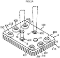
- FIG. 2A is a perspective view illustrating a test piece, and is a view for describing a state where a reference liquid and a sample liquid are injected.
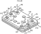
- FIG. 2B is a perspective view illustrating a test piece and is a view for describing a state of connection to a probe with which an analyzer is provided.
- the test piece 100 illustrated in FIGs. 1A , 2A and 2B is used for ion concentration measurement of ion species (for example, sodium ion, potassium ion, and chloride ion) in a sample liquid (for example, a biological sample such as blood, urine, saliva, or a spinal fluid, or an adjusted liquid of such a biological sample).
- a sample liquid for example, a biological sample such as blood, urine, saliva, or a spinal fluid, or an adjusted liquid of such a biological sample.
- the test piece 100 is configured such that the ion concentration in the sample liquid can be quantitatively determined by the potential difference generated between the sample liquid and a reference liquid having a known ion concentration.
- the test piece 100 illustrated in FIGs. 1A , 2A and 2B is formed in a three-layered structure.
- the test piece 100 includes a substrate 2, a mid-layer 3 (resist) formed on the substrate 2, and a cover 4 formed on the mid-layer 3.
- the test piece 100 has a structure which enables a measurement of respective potential differences with respect to three kinds of ions.
- the substrate 2 is formed by a resin material (for example, polyester) in an elongated rectangular manner.
- Six internal electrodes are formed on the substrate 2.
- the six internal electrodes are formed from three sample liquid electrodes 20A to 20C and three reference liquid electrodes 20D to 20F.
- the sample liquid electrodes 20A to 20C and the reference liquid electrodes 20D to 20F can be formed collectively by, for example, a printing procedure using a silver paste, a silver/silver chloride paste, or the like, or a deposition sputtering procedure.
- the sample liquid electrodes 20A to 20C include terminal sections 21A to 21C and liquid receiving sections 22A to 22C, respectively.
- the reference liquid electrodes 20D to 20F include terminal sections 21D to 21F and liquid receiving sections 22D to 22F, respectively.
- the sample liquid electrodes 20A to 20C include conductor wiring sections 23A to 23C for connection between the terminal sections 21A to 21C and the liquid receiving sections 22A to 22C, respectively.
- the reference liquid electrodes 20D to 20F include conductor wiring sections 23D to 23F for connection between the terminal sections 21D to 21F and the liquid receiving sections 22D to 22F, respectively.
- the terminal sections 21A to 21C and the terminal sections 21D to 21F are each arranged at a terminal of the substrate 2.
- the liquid receiving sections 22A to 22C and the liquid receiving sections 22D to 22F are each arranged at the center of the substrate 2.
- the terminal sections 21A to 21C are connected to the liquid receiving sections 22A to 22C via the conductor wiring sections 23A to 23C, respectively.
- the terminal sections 21D to 21F are connected to the liquid receiving sections 22D to 22F via the conductor wiring sections 23D to 23F, respectively.
- the respective potential differences generated between the liquid receiving section 22A and the liquid receiving section 22D, between the liquid receiving section 22B and the liquid receiving section 22E, and between the liquid receiving section 22C and the liquid receiving section 22F are measured by the terminal sections 21A to 21C and the terminal sections 21D to 21F.
- the mid-layer 3 illustrated in FIGs. 1A , 2A and 2B is formed from two layers of an upper mid-layer 3A (upper layer resist) and a lower mid-layer 3B (lower layer resist).
- the mid-layer 3 has through holes 30A to 30C formed on respective regions corresponding to the terminal sections 21A to 21C, and has through holes 30D to 30F formed on respective regions corresponding to the terminal sections 21D to 21F.
- the lower mid-layer 3B of the mid-layer 3 has communication holes 31A to 31C formed on respective regions corresponding to the liquid receiving sections 22A to 22C, and communication holes 31D to 31F formed on respective regions corresponding to the liquid receiving sections 22D to 22F.
- the communication holes 31A to 31C and the communication holes 31D to 31F retain ion-selective membranes 32A to 32C and ion-selective membranes 32D to 32F each for selective permeation of specified ion species, respectively. It is noted that a section including the ion-selective membranes 32A to 32C and the ion-selective membranes 32D to 32F corresponds to an ion-selective electrode according to one embodiment of the present disclosure.
- FIG. 1B is a schematic view illustrating a section of the test piece 100 illustrated in FIG. 1A , corresponding to an ion-selective electrode according to one embodiment of the present disclosure.
- An ion-selective electrode 110 includes ion-selective membranes 32A to 32C and ion-selective membranes 32D to 32F.
- the ion-selective electrode 110 further includes sample liquid electrodes 20A to 20C and reference liquid electrodes 20D to 20F.
- the test piece 100 illustrated in FIGs. 1A , 2A and 2B is formed so that the ion-selective membrane 32A and the ion-selective membrane 32D cause selective permeation of a potassium ion, as illustrated in FIG. 1A . Further, the test piece 100 is formed so that the ion-selective membrane 32B and the ion-selective membrane 32E allow for selective permeation of a chloride ion. The test pieces 100 are each formed so that the ion-selective membrane 32C and the ion-selective membrane 32F allow for selective permeation of a sodium ion.
- the ion-selective membranes 32A to 32C and the ion-selective membranes 32D to 32F are formed as follows.
- the communication holes 31A to 31C and the communication holes 31D to 31F are coated with the liquid film-forming resin composition for ion-selective membrane formation, thereby forming respective coating films.
- the respective coating films are dried, thereby forming the ion-selective membranes 32A to 32C and the ion-selective membranes 32D to 32F. That is, as the communication holes 31Ato 31F are provided corresponding to the liquid receiving sections 22A to 22F, the ion-selective membranes 32A to 32F are formed on the liquid receiving sections 22A to 22F, respectively.
- the ion-selective membrane 32A and the ion-selective membrane 32D, and the ion-selective membrane 32C and the ion-selective membrane 32F, which are cation-selective membranes, are each preferably formed by the liquid film-forming resin composition for ion-selective membrane formation, for the purpose of an enhancement in simultaneous repeatability.
- a liquid retention hole 33A and a liquid retention hole 33D are formed at the center of the upper mid-layer 3A.
- the liquid retention hole 33A is for retaining a sample liquid
- the liquid retention hole 33D is for retaining a reference liquid.
- the liquid retention hole 33A and the liquid retention hole 33D are mutually connected via a notch 34.
- the notch 34 is provided with a bridge 35 arranged for allowing for travelling of any ion.
- the bridge 35 not only allows a sample liquid to be retained in the liquid retention hole 33A, but also allows a short-circuit to be generated between the sample liquid and a reference liquid when the reference liquid is retained in the liquid retention hole 33D.
- the upper mid-layer 3A and the lower mid-layer 3B are each formed by, for example, printing on the substrate 2 a curable resin such as an ultraviolet curing resin by use of a mask, and then cuing the curable resin by UV irradiation.
- the upper mid-layer 3A and the lower mid-layer 3B are formed by using different masks.
- the upper mid-layer 3A and the lower mid-layer 3B may be obtained by repeating such formation multiple times so that an objective thickness is obtained.
- a liquid receiving port 40S for feeding a sample liquid S, a liquid receiving port 40R for feeding a reference liquid R, and an air vent hole 41 are formed on each cover 4 of the test piece 100 illustrated in FIGs. 1A , 2A and 2B .
- the liquid receiving port 40S is provided for feeding the sample liquid S to the liquid retention hole 33A
- the liquid receiving port 40R is provided for feeding the reference liquid R to the liquid retention hole 33D.
- the air vent holes 41 are provided for discharging air in a space formed by the liquid retention holes 33A and 33D and also the cover 4.
- Through holes 42A to 42C are formed on respective regions corresponding to the terminal sections 21A to 21C
- through holes 42D to 42F are formed on respective regions corresponding to the terminal sections 21D to 21F, on the cover 4.
- the terminal sections 21A to 21C are exposed outwards via the through holes 30A to 30C and the through holes 42A to 42C formed on the mid-layer 3 and the cover 4, respectively.
- the terminal sections 21D to 21F are exposed outwards via the through holes 30D to 30F and the through holes 42D to 42F formed on the mid-layer 3 and the cover 4, respectively.
- the terminal sections 21A to 21C can be brought into contact with a probe P2, a probe P4, and a probe P6 represented by a dashed line for potential difference measurement, through the through holes 30A to 30C and the through holes 42A to 42C, respectively, as illustrated in FIG. 2B .
- terminal sections 21D to 21F can be brought into contact with a probe P1, a probe P3, and a probe P5 represented by a dashed line for potential difference measurement, through the through holes 30D to 30F and the through holes 42D to 42F, respectively.
- the sample liquid S and the reference liquid R are fed as represented by a dashed line, as illustrated in FIG. 2A .
- air is discharged from the air vent hole 41.
- the sample liquid S fed from the liquid receiving port 40S of the test piece 100 is filled in the liquid retention hole 33A, and the reference liquid R fed from the liquid receiving port 40R is filled in the liquid retention hole 33D.
- a short-circuit via a bridge 35 is generated between the sample liquid S filled in the liquid retention hole 33A and the reference liquid R filled in the liquid retention hole 33D.
- the sample liquid S contains a potassium ion, which selectively permeates the ion-selective membrane 32A, a chloride ion, which selectively permeates the ion-selective membrane 32B, and a sodium ion, which selectively permeates the ion-selective membrane 32C, respectively.
- a potassium ion reaches the liquid receiving section 22A
- a chloride ion reaches the liquid receiving section 22B
- a sodium ion reaches the liquid receiving section 22C, respectively.
- the reference liquid R contains a potassium ion, which selectively permeates the ion-selective membrane 32D, a chloride ion, which selectively permeates the ion-selective membrane 32E, and a sodium ion, which selectively permeates the ion-selective membrane 32F, respectively.
- a potassium ion reaches the liquid receiving section 22D
- a chloride ion reaches the liquid receiving section 22E
- a sodium ion reaches the liquid receiving section 22F, respectively.
- a short-circuit is generated between the sample liquid S and the reference liquid R, whereby the respective potential differences due to the differences in ion concentration between the liquid receiving section 22A and the liquid receiving section 22D, between the liquid receiving section 22B and the liquid receiving section 22E, and between the liquid receiving section 22C and the liquid receiving section 22F are generated.
- potential differences generated can be measured by, for example, mounting the test piece 100 to an analyzer described below.
- the analyzer is provided with a test piece-mounting section that mounts a test piece according to one aspect of the present disclosure, and an analyzer body.
- FIG. 3 is a perspective view representing an analyzer to which any of the test piece 100 illustrated in FIGs. 1A , 2A and 2B are to be mounted.
- An analyzer 200 is an apparatus that is used with mounting the test piece 100 and that computes an ion concentration based on a potential difference measured.
- the analyzer is provided with an analyzer body 202 and a test piece-mounting section 204 provided on the analyzer body 202.
- the analyzer body 202 contains a potential difference measurement circuit not illustrated, and probes P1 to P6 for contacting the terminal sections 21A to 21C and the terminal sections 21D to 21F of the test piece 100 respectively (see FIG. 2B ).
- the probes P1 to P6 are formed as a pair of the probe P1 and the probe P2, a pair of the probe P3 and the probe P4, and a pair of the probe P5 and the probe P6, and each of the pairs are connected to the potential difference measurement circuit.
- the test piece-mounting section 204 is provided so as to be able to mount the test piece 100, and is formed so as to be slidable into the analyzer body 202.
- the test piece 100 is mounted to the test piece-mounting section 204, and the sample liquid S is fed to the liquid receiving port 40S of the test piece 100 and the reference liquid R is fed to the liquid receiving port 40R of the test piece 100.
- the test piece 100 together with the test piece-mounting section 204 is slid into the analyzer body 202.
- the test piece 100 slid into the analyzer body 202 is brought into contact with the terminal sections 21A to 21F, and the probes P1 to P6 respectively corresponding to such terminal sections.
- the test piece 100 brought into contact with the probes P1 to P6 is controlled to be at a predetermined temperature (for example, 37°C) to start potential difference measurement.
- a potential difference generated between the liquid receiving section 22A and the liquid receiving section 22D can be determined by, for example, bring the probe P2 into contact with the terminal section 21A and bring the probe P1 into contact with the terminal section 21D, and performing measurement in the potential difference measurement circuit connected to the probe P1 and the probe P2.
- a potential difference generated between the liquid receiving section 22B and the liquid receiving section 22E can be measured by the potential difference measurement circuit connected to the probe P3 and the probe P4.
- a potential difference generated between the liquid receiving section 22C and the liquid receiving section 22F can be measured by the potential difference measurement circuit connected to the probe P5 and the probe P6.
- Computing of a concentration of a specified ion is performed by, for example, running a computing program based on the measurement value of the potential difference.
- the computing program is created, for example, so that the ion concentration is computed by assigning the measurement value in a calibration curve created based on the Nernst equation.
- liquid film-forming resin compositions for formation of a sodium ion-selective membrane (Na ion-selective membrane) and a potassium ion-selective membrane (K ion-selective membrane), to which no dielectric material was added were prepared.
- the liquid film-forming resin compositions for formation of a Na ion-selective membrane and a K ion-selective membrane were prepared so that the content of each material in terms of the amount with respect to the solid contents of such ion-selective membranes was within the respective ranges disclosed above.
- Each material for use in the liquid film-forming resin compositions for formation of a Na ion-selective membrane and a K ion-selective membrane is as follows.
- rutile titanium dioxide particles TiO 2 : having a dielectric constant of 83
- Table 1 the respective liquid film-forming resin compositions for formation of a sodium ion-selective membrane and a potassium ion-selective membrane, in which the dielectric material was dispersed, were prepared.
- Electrolyte silver chloride
- Solvent tetrahydrofuran
- Binder resin vinyl chloride/vinyl acetate copolymer, vinyl chloride/vinyl acetate/vinyl alcohol copolymer
- Ionophore bis(12-crown-4)
- Anion eliminating agent trioctylmethylammonium chloride, sodium tetrakis[3,5-bis(trifluoromethyl)phenyl]borate
- Plasticizer 2-nitrophenyl octyl ether
- Electrolyte silver chloride
- Solvent tetrahydrofuran
- Binder resin vinyl chloride/vinyl acetate/vinyl alcohol copolymer
- Ionophore bis(15-crown-5)
- Anion eliminating agent trioctylmethylammonium chloride, potassium tetrakis(4-chlorophenyl)borate
- Plasticizer 2-nitrophenyl octyl ether
- thermosetting silver paste was printed on a substrate by use of a mask (200-mesh, having a thickness of 20 ⁇ m) to prepare sample liquid electrodes and reference liquid electrodes.
- the substrate on which printing was made was heated to cure a resin component in the paste.
- a lower layer resist was obtained as follows. An ultraviolet curing resist was printed on the substrate by use of a mask (300-mesh, having a thickness of 40 ⁇ m) and irradiated with ultraviolet light at an output of 6 kW for 5 seconds.
- the operation including the printing of the ultraviolet curing resist and the UV irradiation were repeated three times in total, thereby forming the lower layer resist so that the thickness was 50 ⁇ m.
- a diameter of each communication hole was 3.2 mm.
- An upper layer resist was formed according to the same procedure as that of the lower layer resist, except that a different mask was used, so that the thickness was 50 ⁇ m.
- silver chloride layers were formed on liquid receiving sections. After formation of the silver chloride layers, each of the liquid film-forming resin compositions for ion-selective membrane formation, in which the titanium dioxide particles were dispersed, was injected to each communication hole for coating the communication hole, and the resultant film was dried.
- a test piece was produced which was provided with an ion-selective electrode including a sodium ion-selective membrane in which the titanium dioxide particles were dispersed, and an ion-selective electrode including a potassium ion-selective membrane in which the titanium dioxide particles were dispersed.
- a chloride ion-selective membrane provided on the test piece was obtained by using a known liquid film-forming resin composition for chloride ion-selective membrane formation.
- a test piece was produced in the same manner as in Example 1 except that the liquid film-forming resin composition was prepared and used without adding the dielectric material.
- Example 2 In place of the liquid film-forming resin composition in which the titanium dioxide particles were dispersed, prepared in Example 1, a liquid film-forming resin composition in which hafnium oxide particles (having a dielectric constant of 25) were dispersed, produced by the same procedure as in Example 1, was prepared so that contents of components with respect to a solid content of the ion-selective membrane was as shown in Table 1 (Example 2).
- Example 3 In place of the liquid film-forming resin composition in which the titanium dioxide particles were dispersed, prepared in Example 1, a liquid film-forming resin composition in which zirconium oxide particles (having a dielectric constant of 30) were dispersed, produced by the same procedure as in Example 1, was prepared so that contents of components with respect to a solid content of the ion-selective membrane was as shown in Table 1 (Example 3).
- Example 2 a liquid film-forming resin composition in which iron oxide particles (having a dielectric constant of 1.4) were dispersed, produced by the same procedure as in Example 1, was prepared so that contents of components with respect to a solid content of the ion-selective membrane was as shown in Table 1 (Comparative Example 2).
- Example 1 Dielectric material Kind Na ion-selective membrane K ion-selective membrane % by mass % by mass
- Example 1 Titanium dioxide (dielectric constant: 83) 2 2 3 3 4 4 6 6 8 8 10 10
- Example 2 Hafnium oxide (dielectric constant: 25) 2 2 3 3 4 4 6 6 8 8
- Example 3 Zirconium oxide (dielectric constant: 30) 2 2 3 3 4 4 6 6 8 - Comparative Example 1 Not added 0 0 Comparative Example 2 Iron oxide (dielectric constant: 1.4) 3 3 3 3
- the potential difference was measured as follows.
- the test piece obtained in each Example was mounted to an analyzer (altered model of electrode-type electrolyte measurement device "SPOTCHEM EL" (trade name, manufactured by ARKRAY, Inc.)).
- a sample liquid used was a standard serum.
- a reference liquid included in a conventional test piece (E-PLATE, manufactured by ARKRAY, Inc.) was used, and the sample liquid and the reference liquid were fed to each feeding hole of the test piece, and then the potential difference was measured.
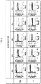
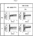
- the measurement results are shown in FIGs. 4 to 7 .
- the results shown in FIGs. 4 to 7 indicate the potential differences individually measured with respect to test pieces made by use of the same material liquid, in the time course. The better the convergence in the time course is, the better the simultaneous repeatability is.
- FIGs. 4 to 6 are each a graph representing the results obtained by analysis of the sample liquid by use of the test piece obtained in each Example.
- FIG. 7 is a graph representing the results obtained by analysis of the sample liquid by use of the test piece obtained in each Comparative Example.
- the upper stage represents the measurement results of a Na ion and the lower stage represents the measurement results of a K ion.
- the sign "%" expressed with reference to the amount of the dielectric material added means "% by mass".
- Comparative Example 2 It was found as represented in FIG. 7 that the convergence in the time course in Comparative Example 2 was equal to or inferior relative to that in Comparative Example 1. In other words, it was found from Comparative Example 2 that no effect of enhancing simultaneous repeatability was exerted when an ion-selective membrane including a dielectric material having a dielectric constant of less than 10 is used.
- an ion-selective electrode including an ion-selective membrane including a dielectric material having a dielectric constant of 10 or more exhibits excellent simultaneous repeatability.
- the dielectric constant of the dielectric material was preferably 25 or more, and was more preferably 50 or more because Example 1 imparted the best simultaneous repeatability.
Landscapes
- Chemical & Material Sciences (AREA)
- Life Sciences & Earth Sciences (AREA)
- Health & Medical Sciences (AREA)
- Physics & Mathematics (AREA)
- Chemical Kinetics & Catalysis (AREA)
- Electrochemistry (AREA)
- Molecular Biology (AREA)
- Analytical Chemistry (AREA)
- Biochemistry (AREA)
- General Health & Medical Sciences (AREA)
- General Physics & Mathematics (AREA)
- Immunology (AREA)
- Pathology (AREA)
- Sampling And Sample Adjustment (AREA)
- Investigating Or Analyzing Materials By The Use Of Electric Means (AREA)
Abstract
This disclosure provides an ion-selective electrode (2 and 3) offering enhanced in simultaneous repeatability. The ion-selective electrode is composed of internal electrodes being coated with an ion-selective membrane comprising a binder resin, an ionophore and a dielectric material having a dielectric constant of 10 or more. A test piece (100) comprising the ion-selective electrode and a liquid receiving section (40S, 40R) is further disclosed. The ion-selective electrode is provided with: a pair of internal electrodes (20A-20F); and an ion-selective membrane (32A-32F) which is provided at respective positions corresponding to the internal electrodes.
Description
- The present disclosure relates to an ion-selective electrode, a test piece, and an analyzer.
- Examples of means known for measuring ion concentration in a sample includes ion-selective electrodes. Ion concentration measurement with ion-selective electrodes is performed by, for example, generating a short-circuit between a reference liquid (liquid having a known ion concentration) and a sample liquid (liquid having an unknown ion concentration), measuring a potential difference therebetween, and then measuring an ion concentration of the sample liquid based on the resulting potential difference.
- Ion-selective electrodes are at least provided with sensing sections exhibiting ion sensitivity, and have been variously studied for enhancement in response precision of such sensing sections.
- For example, Japanese Patent Application Laid-Open (
JP-A) No. H08-134024 -
JP-A No. 2008-232660 -
JP-A No. 2017-026637 - Ion-selective electrodes are required to have simultaneous repeatability. The "simultaneous repeatability" represents the precision in repeated measurement (repeatability precision) in a short time under certain measurement conditions, for example, in the same examination room, by the same examiner, and with the same apparatus.
- However, conventional ion-selective electrodes may cause the measurement variation and there is a need to further improve simultaneous repeatability.
- An aim of the present disclosure is to provide an ion-selective electrode with enhanced simultaneous repeatability, a test piece using the ion-selective electrode, and an analyzer using the test piece.
- The following aspect and optional features are encompassed in solutions for solving the above problems.
- <1> An ion-selective electrode comprising: a pair of internal electrodes; and an ion-selective membrane provided at respective positions corresponding to the internal electrodes, the ion-selective membrane comprising a binder resin, an ionophore, and a dielectric material having a dielectric constant of 10 or more, optionally 25 or more, or optionally 50 or more.
- The pair of internal electrodes may comprise a sample electrode and a reference electrode.
- The ion-selective membrane may comprise a pair of ion-selective membranes each provided at the position of a corresponding internal electrode.
- <2> The ion-selective electrode according to <1>, wherein the dielectric material is in a form of a solid.
- <3> The ion-selective electrode according to <1> or <2>, wherein the dielectric material comprises at least one selected from the group consisting of a carbon material and a metal oxide.
- <4> The ion-selective electrode according to any one of <1> to <3>, wherein the dielectric material is in a form of particles.
- <5> The ion-selective electrode according to any one of <1> to <4>, wherein the dielectric material comprises at least one selected from the group consisting of barium titanate, titanium oxide, titanium dioxide, hafnium oxide, and zirconium oxide.
- <6> The ion-selective electrode according to any one of <1> to <5>, wherein a content of the dielectric material in the ion-selective membrane is from 2% by mass to 10% by mass with respect to a solid content of the ion-selective membrane.
- <7> The ion-selective electrode according to any one of <1> to <6>, wherein a content of the dielectric material in the ion-selective membrane is from 2% by mass to 8% by mass with respect to a solid content of the ion-selective membrane.
- <8> The ion-selective electrode according to any one of <1> to <7>, wherein the dielectric material comprises titanium dioxide, and a content of the dielectric material in the ion-selective membrane is from 2% by mass to 8% by mass with respect to a solid content of the ion-selective membrane.
- <9> The ion-selective electrode according to any one of <1> to <8>, wherein the dielectric material is substantially uniformly dispersed throughout the ion-selective membrane.
- <10> The ion-selective electrode according to <9>, wherein molecules of the binder resin form a three-dimensional network structure, and the dielectric material is physically fixed inside the three-dimensional network structure.
- <11> The ion-selective electrode according to any one of <1> to <10>, wherein the ion-selective membrane is a cation-selective membrane.
- <12> The ion-selective electrode according to <11>, wherein the cation-selective membrane is a sodium ion-selective membrane or a potassium ion-selective membrane.
- <13> The ion-selective electrode according to any one of <1> to <12>, wherein the ion-selective membrane is directly disposed on the internal electrodes.
- <14> The ion-selective electrode according to any one of <1> to <13>, wherein a content of the binder resin in the ion-selective membrane is from 18% by mass to 35% by mass with respect to a solid content of the ion-selective membrane, and a content of the ionophore in the ion-selective membrane is from 3% by mass to 10% by mass with respect to a solid content of the ion-selective membrane.
- <15> The ion-selective electrode according to any one of <1> to <14>, wherein the ion-selective membrane further comprises: a plasticizer at a content of from 50% by mass to 70% by mass with respect to a solid content of the ion-selective membrane; an ion eliminating agent at a content of from 0.6% by mass to 1.1% by mass with respect to a solid content of the ion-selective membrane; and an electrolyte at a content of from 0.23% by mass to 0.37% by mass with respect to a solid content of the ion-selective membrane.
- <16> A test piece comprising: the ion-selective electrode according to any one of <1> to <15>; and a liquid receiving section.
- According to the present disclosure, an ion-selective electrode having enhanced simultaneous repeatability, a test piece using the ion-selective electrode, and an analyzer using the test piece are provided.
- Certain embodiments will now be described in greater detail by way of example only and with reference to the accompanying drawings in which:
-
FIG. 1A is an exploded view illustrating a test piece according to an embodiment of the present disclosure; -
FIG. 1B is a schematic view illustrating a section of the test piece illustrated inFIG. 1A , the section corresponding to an ion-selective electrode according to an embodiment of the present disclosure; -
FIG. 2A is a perspective view illustrating a test piece according to an embodiment of the present disclosure; -
FIG. 2B is a perspective view illustrating a test piece according to an embodiment of the present disclosure; -
FIG. 3 is a perspective view illustrating an analyzer; -
FIG. 4 is a graph representing the result obtained by analyzing the sample liquid with the test piece obtained in Example 1; -
FIG. 5 is a graph representing the result obtained by analyzing the sample liquid with the test piece obtained in Example 2; -
FIG. 6 is a graph representing the result obtained by analyzing the sample liquid with the test piece obtained in Example 3; and -
FIG. 7 is a graph representing the results obtained by analyzing the sample liquid with the test piece obtained in each Comparative Example. - Hereinafter, an embodiment of an ion-selective electrode will be described.
- The numerical value range herein represented by "(from) ... to ..." means that the range encompasses the respective numerical values described before and after "to" as the lower limit and the upper limit, respectively.
- The term "step" herein encompasses not only an independent step, but also a step that can achieve a predetermined object even when it cannot be clearly distinguished from other steps.
- An ion-selective electrode according to one aspect of the present disclosure includes a pair of internal electrodes and an ion-selective membrane provided at respective positions corresponding to the internal electrodes. The ion-selective membrane is formed so as to include a binder resin, an ionophore, and a dielectric material having a dielectric constant of 10 or more (hereinafter, sometimes simply referred to as a "dielectric material".).
- Various ion-selective electrodes are known as disclosed in, for example, the patent literature as set forth above.
- The ion-selective membrane equipped with the ion-selective electrode disclosed in
JP-A No. H08-134024 JP-A No. H08-134024 - The ion-selective electrode disclosed in
JP-A No. 2008-232660 JP-A No. 2008-232660 - The ion-selective electrode disclosed in
JP-A No. 2017-026637 JP-A No. 2017-026637 JP-A No. 2017-026637 - Thus, such conventional ion-selective electrodes are not sufficient in simultaneous repeatability, and there is a need to improve measurement precision.
- Examples of a solution for enhancing simultaneous repeatability of an ion-selective electrode include increasing electric conductivity of an ion-selective membrane with which an ion-selective electrode is provided. Having considered that such an increase in electric conductivity of an ion-selective membrane can be achieved by using a material with high electric conductivity, the present inventor focused on incorporation of a material having a high dielectric constant. As a result, it was found that simultaneous repeatability of an ion-selective electrode is enhanced by forming an ion-selective membrane containing, in addition to a binder resin and an ionophore, a dielectric material exhibiting a dielectric constant of 10 or more.
- Hereinafter, an ion-selective membrane with which an ion-selective electrode according to one embodiment of the present disclosure is provided will be described. The ion-selective membrane includes a binder resin, an ionophore, and a dielectric material. The ion-selective membrane may include, if necessary, additive(s) such as a plasticizer, an electrolyte, and/or an ion eliminating agent.
- Hereinafter, the materials for forming the ion-selective membrane will be described.
- The binder resin is not particularly limited. Specific examples of the binder resin include polyvinyl chloride, polyvinylidene chloride, polyacrylonitrile, polyurethane, polyvinyl acetate, a silicone elastomer, polyvinyl alcohol, cellulose ester, polycarbonate, a vinyl chloride/vinyl acetate copolymer, a vinyl chloride/vinyl acetate/vinyl alcohol copolymer, and a vinyl chloride/vinylidene chloride copolymer. In particular, the binder resin is preferably a resin including a structural unit derived from vinyl chloride (at least one selected from the group consisting of a homopolymer of a structural unit derived from vinyl chloride and a copolymer including a structural unit derived from vinyl chloride) from the viewpoint of an enhancement in simultaneous repeatability. More preferable examples of the resin including a structural unit derived from vinyl chloride includes polyvinyl chloride, a copolymer of vinyl chloride/vinyl acetate, and a terpolymer of vinyl chloride/vinyl acetate/vinyl alcohol. The binder resin may be used singly, or in combination of two or more kinds thereof.
- A content of the binder resin in the ion-selective membrane is preferably from 18% by mass to 35% by mass with respect to a solid content of the ion-selective membrane. The lower limit of the content of the binder resin is more preferably 20% by mass or more. The upper limit of the content of the binder resin is more preferably 30% by mass or less.
- An ionophore is a chemical substance having the ability to increase the permeability of an ion to be measured. The ionophore binds to the ion to be measured and passes through the ion-selective membrane, thereby having the ion to pass (namely, carrier ionophore). The ionophore is not particularly limited. The ionophore may be selected depending on the kind of the ion to be measured.
- In a case in which the ion-selective membrane is a potassium selective membrane, examples of the ionophore include valinomycin, cyclic polyether, tetralactone, macrolide actin, enniatin, potassium tetraphenylborate, and derivatives thereof. In particular, the ionophore for use in a potassium selective membrane is preferably cyclic polyether, more preferably a compound having a bis(crown ether) structure, and still more preferably bis[(benzo-15-crown-5)-4-methyl]pimelate ((bis(benzo-15-crown-5)).
- In a case in which the ion-selective membrane is a sodium ion-selective membrane, examples of the ionophore include monensin sodium, methyl monensin, cyclic polyether, tetralactone, macrolide actin, enniatin, sodium tetraphenylborate, a calixarene compound, and derivatives thereof. In particular, the ionophore for use in a sodium ion-selective membrane is preferably cyclic polyether, more preferably a compound having a bis(crown ether) structure, and still more preferably bis[(12-crown-4)methyl]-2-dodecyl-2-methylmalonate (bis(12-crown-4)).
- A content of the ionophore in the ion-selective membrane is preferably from 3% by mass to 10% by mass with respect to a solid content of the ion-selective membrane. The lower limit of the content of the ionophore is more preferably 4% by mass or more. The upper limit of the content of the ionophore is more preferably 8% by mass or less.
- A dielectric material herein means one that exhibits a dielectric constant of 10 or more. A form of the dielectric material is not particularly limited as long as the dielectric constant is 10 or more. The dielectric material may be in a form of a liquid or a solid. From the viewpoint of an enhancement in simultaneous repeatability, the dielectric material is preferably in any form so as to be hardly dissolved in a liquid film-forming resin composition for providing the ion-selective membrane. The dielectric material is more preferably in a form of a solid that is hardly dissolved in the liquid film-forming resin composition, from such a viewpoint. Herein, such a dielectric material in the form of a solid is any dielectric material that is hardly dissolved in the liquid film-forming resin composition and maintains its solid form even when mixed with the liquid film-forming resin composition, and that maintains its solid form even when contained in the ion-selective membrane. The dielectric material in the form of a solid is hardly dissolved even when brought into contact with a sample liquid and a reference liquid. That is, the dielectric material in the form of a solid is a dielectric material that is hardly dissolved in a liquid. The dielectric material is still more preferably in a form of particles. In a case in which the dielectric material is in the form of particles, the dielectric material can be easily dispersed in the ion-selective membrane, thereby further enhancing simultaneous repeatability. The shape of the particles is not particularly limited, and examples thereof include spherical, granulate, flake, whisker, and rod shapes. Herein, the dielectric material having a dielectric constant of 10 or more is distinguished from a plasticizer, and does not have any effect as a plasticizer.
- The dielectric constant of the dielectric material may be 15 or more, preferably 25 or more, more preferably 50 or more. The upper limit of the dielectric material is not particularly limited, and examples thereof include 30,000 or less.
- The method of measuring the dielectric constant is a method according to the method of measuring the relative permittivity tangent prescribed in JIS C 2138:2007 ("Electrical insulating materials - Methods for the determination of the relative permittivity and dielectric dissipation factor"), which substantially corresponds to IEC 60250:1969.
- A kind of the dielectric material is not particularly limited. The dielectric material may be an inorganic material that is hardly dissolved in the liquid film-forming resin composition and that is hardly dissolved even when brought into contact with a sample liquid and a reference liquid, from the viewpoint of an enhancement in simultaneous repeatability. The inorganic material may be preferably at least one of a carbon material or a metal oxide.
- Herein, the phrase that a component is "hardly dissolved" in the liquid film-forming resin composition means that a solubility of the component in the liquid film-forming resin composition at 20°C is less than 5% by mass, namely, an amount of the component which can be dissolved in the liquid film-forming resin composition at 20°C is less than 5% by mass with respect to a total mass of the liquid film-forming resin composition.
- Examples of the carbon material include graphite (natural graphite, artificial graphite), carbon black, diamond, carbon nanotube, carbon nanofiber, carbon fiber, and fullerene. Such carbon materials may be used singly, or in combination of two or more kinds thereof.
- The metal oxide may be, for example, an oxide or composite oxide of a transition metal. Specific examples of the metal oxide include barium titanate, calcium titanate, strontium titanate, titanium oxide, titanium dioxide, hafnium oxide, and zirconium oxide. The metal oxide may be preferably at least one selected from the group consisting of barium titanate (BaTiO3), titanium oxide (TiO), titanium dioxide (TiO2), hafnium oxide (HfO2), and zirconium oxide (ZrO2).
- In particular, the dielectric material having a dielectric constant of 10 or more is preferably at least one selected from the group consisting of barium titanate, titanium oxide, titanium dioxide, hafnium oxide, and zirconium oxide, and more preferably titanium dioxide, from the viewpoint of an enhancement in simultaneous repeatability.
- A content of the dielectric material in the ion-selective membrane may be 1% by mass or more with respect to a solid content of the ion-selective membrane, from the viewpoint of an enhancement in simultaneous repeatability. The upper limit is not particularly limited, and examples thereof include 15% by mass or less. The content of the dielectric material may be from 2% by mass to 10% by mass with respect to a solid content of the ion-selective membrane, from the viewpoint of a greater enhancement in simultaneous repeatability. The content may be from 2% by mass to 8% by mass from the same viewpoint. The lower limit of the content of the dielectric material is preferably 3% by mass or more. The upper limit of the content of the dielectric material is preferably 6% by mass or less, more preferably 5% by mass or less.
- A combination of the dielectric material contained in the ion-selective membrane with the content of the dielectric material is preferably a combination of a dielectric material containing titanium dioxide with a content of the dielectric material of from 2% by mass to 8% by mass with respect to a solid content of the ion-selective membrane, more preferably a combination of a dielectric material containing titanium dioxide with a content of the titanium dioxide of from 2% by mass to 5% by mass with respect to a solid content of the ion-selective membrane.
- In addition to the binder resin, the ionophore, and the dielectric material having a dielectric constant of 10 or more, the ion-selective membrane may be formed by further using, if necessary, additive(s) such as a plasticizer, an ion eliminating agent, and/or an electrolyte.
- Flexibility of the ion-selective membrane may be enhanced by incorporating a plasticizer. Therefore, the plasticizer has, for example, the effect of suppressing the occurrence of cracking of the ion-selective membrane. The plasticizer preferably has a high dielectric constant from the viewpoint of an enhancement in simultaneous repeatability, and the dielectric constant of the plasticizer may be, for example, in a range from 10 to 24. The dielectric constant of the plasticizer corresponds to the numerical value obtained by the measurement method described above. Herein, the plasticizer is distinguished from the above dielectric material.
- The plasticizer is not particularly limited. Specific examples of the plasticizer include 2-nitrophenyl octyl ether (NPOE), 2-nitrophenyl dodecyl ether (NPDE), 2-nitrophenyl phenyl ether (NPPE), dioctyl adipate (DOA), bis(1-butylpentyl) adipate (BBPA), dibutyl sebacate (DBS), dibutyl phthalate (DBP), dioctyl phthalate (DOP), dioctyl phenyl phosphoric acid (DOPP), dioctyl sebacate (DOS), and dibenzyl ether (DBE). In particular, a nitrophenyl alkyl ether compound is preferable, and 2-nitrophenyl octyl ether (NPOE) is more preferable.
- A content of the plasticizer in the ion-selective membrane is preferably from 50% by mass to 70% by mass with respect to a solid content of the ion-selective membrane. The lower limit of the content of the plasticizer is more preferably 52% by mass or more. The upper limit of the content of the plasticizer is more preferably 67% by mass or less.
- An ion eliminating agent may be selected depending on the kind of an ion to be measured. In a case in which the ion-selective membrane is a cation-selective membrane, the ion eliminating agent to be used is preferably an anion eliminating agent. The influence of an anion on measurement due to interference may be suppressed by using the anion eliminating agent.
- The anion eliminating agent is not particularly limited. Specific examples of the anion eliminating agent include tetraphenylborate salts such as sodium tetrakis[3,5-bis(trifluoromethyl)phenyl]borate (Na-TFPB), potassium tetrakis[3,5-bis(trifluoromethyl)phenyl]borate (K-TFPB), potassium tetrakis(4-chlorophenyl)borate (K-TCPB), sodium tetrakis(4-chlorophenyl)borate (Na-TCPB), potassium tetraphenylborate (K-TPB), sodium tetraphenylborate (Na-TPB), and sodium tetrakis[3,5-bis(1,1,1,3,3,3-hexafluoro-2-methoxy-2-propyl)phenyl]borate. In particular, from the viewpoint of an enhancement in simultaneous repeatability, potassium tetrakis[3,5-bis(trifluoromethyl)phenyl]borate (K-TFPB) is preferable in a case in which the ion-selective membrane is a potassium selective membrane, and sodium tetrakis[3,5-bis(trifluoromethyl)phenyl]borate (Na-TFPB) is preferable in a case in which the ion-selective membrane is a sodium ion-selective membrane.
- In a case in which the ion-selective membrane is a cation-selective membrane, a quaternary ammonium salt may be used in combination with the anion eliminating agent from the viewpoint of an enhancement in simultaneous repeatability. Specific examples of the quaternary ammonium salt include trioctylmethylammonium chloride (TOMAC), tridecylmethylammonium chloride (TDMAC), and tetraoctylammonium chloride. In particular, trioctylmethylammonium chloride (TOMAC) is preferable. The anion eliminating agent to be used is preferably at least one of the tetraphenylborate salt or the quaternary ammonium salt.
- A content of the ion eliminating agent in the ion-selective membrane is preferably from 0.6% by mass to 1.1% by mass with respect to a solid content of the ion-selective membrane. The lower limit of the content of the ion eliminating agent is more preferably 0.7% by mass or more. The upper limit of the content of the ion eliminating agent is more preferably 1.0% by mass or less. The content of the ion eliminating agent may be within the above range even when any one of the tetraphenylborate salt or the quaternary ammonium salt is used, and even when both thereof are used in combination.
- An electrolyte has the effect of aiding electric conducting of the ion-selective membrane. The electrolyte is not particularly limited, and examples thereof include a metal halide. The metal halide may be a metal chloride. Specific examples of the electrolyte include sodium chloride, potassium chloride, silver chloride, silver bromide, and silver iodide.
- A content of the electrolyte in the ion-selective membrane is preferably from 0.23% by mass to 0.37% by mass with respect to a solid content of the ion-selective membrane. The lower limit of the content of the electrolyte is more preferably 0.25% by mass or more. The upper limit of the content of the electrolyte is more preferably 0.34% by mass or less.
- A thickness of the ion-selective membrane is not particularly limited. The thickness of the ion-selective membrane is, for example, in a range from 50 µm to 300 µm.
- An application of the ion-selective membrane is not particularly limited, and examples thereof include an anion-selective membrane for measuring an anion such as a chloride ion; and a cation-selective membrane for measuring a cation such as a sodium ion or a potassium ion. In particular, the ion-selective membrane is preferably a cation-selective membrane, and more preferably a sodium ion-selective membrane or a potassium ion-selective membrane.
- Examples of a preferable method of producing the ion-selective membrane include a method including the following process. 1) A first process of preparing a liquid film-forming resin composition including a binder resin, an ionophore, and a dielectric material having a dielectric constant of 10 or more. 2) A second process of performing coating with the liquid film-forming resin composition to form a coating film. 3) A third process of drying the coating film to form an ion-selective membrane.
- The first process is a process of preparing a liquid film-forming resin composition for ion-selective membrane formation. The liquid film-forming resin composition may be prepared by mixing the binder resin, the ionophore, and the dielectric material having a dielectric constant of 10 or more, and, if necessary, the plasticizer and the electrolyte. The liquid film-forming resin composition is produced by dissolving or dispersing such materials in a solvent. The dissolution or dispersion method is not particularly limited, and a known method using a high-speed blender, a homogenizer, or the like may be adopted.
- Specifically, the liquid film-forming resin composition may be prepared as follows, for example. First, a binder resin and an ionophore, and, if necessary, a plasticizer and an electrolyte are mixed in a solvent, and dissolved therein to prepare a dissolution liquid. Next, a dielectric material having a dielectric constant of 10 or more is added to the dissolution liquid, thereby preparing a liquid film-forming resin composition in which the dielectric material is dispersed. The solvent for use in preparation of the liquid film-forming resin composition is not particularly limited, and examples thereof include organic solvents such as tetrahydrofuran (THF), N-methyl-2-pyrrolidone (NMP), and methyl ethyl ketone (MEK). Such a preparation method by mixing enables forming a liquid film-forming resin composition which has as its matrix the binder resin, molecules of which form a three-dimensional network structure. Respective materials are substantially uniformly dispersed in the liquid film-forming resin composition. As described above, at least the dielectric material is hardly dissolved in the liquid film-forming resin composition and is maintained in the form of a solid, and is maintained in the form of a solid even when contained in the ion-selective membrane, while binding between materials and interaction therebetween are varied depending on materials used. The dielectric material may be present in the organic solvent in a substantially uniformly dispersed state. In embodiments, the dielectric material may be physically fixed to a surface of the binder resin and/or inside of the three-dimensional network structure. Similarly to the dielectric material, the ionophore may be present in an organic solvent in a substantially uniformly dispersed state, and may be fixed on a surface of the binder resin and/or inside of the three-dimensional network structure by physical fixation or weak electric force such as a hydrogen bond. In embodiments, the ionophore may be chemically bound to the binder resin via substitution of the binder resin or crosslinking to the binder resin.
- The second process is a process of performing coating with the liquid film-forming resin composition prepared, to form a coating film. For example, a predetermined region may be coated with the liquid film-forming resin composition prepared. The coating method is not particularly limited. Examples of the coating method include known methods such as a casting method, spray coating, a dipping method, and a spin-off coating method.
- The third process is a process of drying the coating film to form an ion-selective membrane. The drying condition is not particularly limited as long as the coating film can be dried, and examples thereof include conditions of a temperature of from 40°C to 80°C and a time of from 1 minute to 60 minutes. Since the dielectric material and the ionophore are substantially uniformly dispersed in a solvent of the liquid film-forming resin composition as described above, the drying may result in an ion-selective membrane which has the binder resin as a matrix thereof and in which the dielectric material is physically fixed on a surface of the binder resin and/or inside of the three-dimensional network structure, that is, an ion-selective membrane throughout which the dielectric material is in a substantially uniformly dispersed state. The ion-selective membrane thus obtained may further contain the ionophore as a component that is present on a surface of the binder resin and/or inside of the three-dimensional network structure by physical fixation or weak electric force such as a hydrogen bond, namely, as a component that is in a substantially uniformly dispersed state throughout the ion-selective membrane.
- Any method other than such a preparation method can also be used to form an ion-selective membrane by coating with respective materials in a layered structure and drying of the resulting coating film.
- As described above, an ion-selective electrode according to one aspect of the present invention is provided with an ion-selective membrane. An ion-selective electrode according to one aspect of the present invention is provided with the ion-selective membrane and a pair of internal electrodes. The ion-selective electrode may be provided with the ion-selective membrane, a sample internal electrode (sample electrode) and a reference internal electrode (reference electrode). The ion-selective electrode may be provided with the ion-selective membrane, internal electrodes (a sample electrode and a reference electrode), and an internal solution. In a case in which an ion-selective electrode is provided with an internal electrode, the ion-selective membrane may be disposed at any part corresponding to the internal electrode as long as it can be electrically connected to the internal electrode under a condition that a sample liquid and a reference liquid are contained in the ion-selective electrode. For example, the ion-selective membrane may be disposed over the internal electrode. In a case in which the ion-selective membrane is disposed over an internal electrode, the ion-selective membrane may be directly disposed on the internal electrode or may be disposed above the internal electrode with any member interposed therebetween such as a supporting device like a rod, an electro-conductive sheet or a soluble protective film. In a case in which the ion-selective membrane is directly disposed on the internal electrode, the ion-selective membrane can be prepared by, for example, applying a liquid film-forming resin composition for forming the ion-selective membrane onto the internal electrode and drying the applied composition. Alternatively, the ion-selective membrane may be disposed over a surface of a member in contact with a sample liquid, the surface being in contact with the sample liquid. The ion-selective electrode may include one of the ion-selective membranes, or may be provided with two or more of the ion-selective membranes. In a case in which an ion-selective electrode includes two or more of the ion-selective membranes, the ion-selective electrode may include, for example, a sodium ion-selective membrane and a potassium ion-selective membrane. In a case in which an ion-selective electrode is provided with an internal solution, the ion-selective solution may be provided at any part corresponding to the ion-selective membrane and the internal electrode as long as electrically connection of the ion-selective membrane to the internal electrode can be made via the internal solution. For example, the ion-selective membrane and the internal electrode may be placed in a liquid container filled with the internal solution. In this case, as the ion-selective membrane may be provided at any part over the internal electrode, the ion-selective membrane may be directly disposed on the internal electrode or may be disposed above the internal electrode with any member interposed therebetween such as a supporting device like a rod or an electro-conductive sheet.
- Examples of the internal electrode include a metal/metal salt electrode. Examples of the metal/metal salt electrode include a silver/silver halide electrode. Examples of the silver/silver halide electrode include a silver/silver chloride electrode.
- The internal solution is not limited thereto, and examples thereof include an aqueous metal salt solution, and a mixed solution of an aqueous metal salt solution. Specific examples of the aqueous metal salt solution include an aqueous potassium chloride solution, and a mixture of an aqueous potassium chloride solution and an aqueous metal salt solution. In particular, the internal solution is preferably an aqueous potassium chloride solution.
- Examples of a preferable method of producing an ion-selective electrode include a production method including processes similar to those of the method of producing the ion-selective membrane. Specifically, the ion-selective electrode is obtained by the following method. First, a liquid film-forming resin composition is prepared in the same manner as in the first process of the method of producing the ion-selective membrane. Next, the liquid film-forming resin composition prepared in the first process is directly coated on an internal electrode or is coated on a member disposed on an internal electrode, as in the second process of the method of producing the ion-selective membrane. Then, the coating film of the liquid film-forming resin composition is dried to form an ion-selective membrane, thereby providing an ion-selective electrode, in the same manner as in the third process of the method of producing the ion-selective membrane. The processes provide an ion-selective electrode including an ion-selective membrane.
- Examples of the method further include the following production method. First, an ion-selective membrane is produced by the above-described method of producing the ion-selective membrane. Next, the resulting ion-selective membrane is separated from a predetermined region, and attached onto a surface of a member in contact with a sample liquid, the surface being in contact with the sample liquid, according to a known method, thereby producing an ion-selective electrode.
- An ion-selective electrode can be applied to, for example, a pH electrode. An ion-selective electrode according to one aspect of the present disclosure can be applied to an electrode such as an ion-selective electrode for measurement of a concentration of an anion such as a chloride ion; or an ion-selective electrode for measurement of a concentration of a cation such as a sodium ion or a potassium ion. In particular, the ion-selective electrode is suitably applied to an ion-selective electrode for measurement of the concentration of a cation such as a sodium ion or a potassium ion.
- An example of where an ion-selective electrode is applied include a test piece for ion concentration measurement. Examples of a measurement sample for ion concentration measurement include biological samples such as blood, urine, saliva, a spinal fluid, and sweat.
- Next, a test piece will be described. A test piece is provided with the ion-selective electrode according to one aspect of the present invention. Hereinafter, a test piece according to one preferable embodiment of the present invention, which is a test piece provided with the ion-selective electrode including an ion-selective membrane including a binder resin, an ionophore, and a dielectric material having a dielectric constant of 10 or more, and an internal electrode (sample electrode and reference electrode), will be described with reference to drawings. It is remarked that the test piece is not intended to be limited to those described with reference to the drawings.
-
FIG. 1A is an exploded view illustrating a test piece.FIG. 2A is a perspective view illustrating a test piece, and is a view for describing a state where a reference liquid and a sample liquid are injected.FIG. 2B is a perspective view illustrating a test piece and is a view for describing a state of connection to a probe with which an analyzer is provided. - The
test piece 100 illustrated inFIGs. 1A ,2A and2B is used for ion concentration measurement of ion species (for example, sodium ion, potassium ion, and chloride ion) in a sample liquid (for example, a biological sample such as blood, urine, saliva, or a spinal fluid, or an adjusted liquid of such a biological sample). Thetest piece 100 is configured such that the ion concentration in the sample liquid can be quantitatively determined by the potential difference generated between the sample liquid and a reference liquid having a known ion concentration. - The
test piece 100 illustrated inFIGs. 1A ,2A and2B is formed in a three-layered structure. Thetest piece 100 includes asubstrate 2, a mid-layer 3 (resist) formed on thesubstrate 2, and acover 4 formed on themid-layer 3. Thetest piece 100 has a structure which enables a measurement of respective potential differences with respect to three kinds of ions. - As illustrated in
FIG. 1A , thesubstrate 2 is formed by a resin material (for example, polyester) in an elongated rectangular manner. Six internal electrodes are formed on thesubstrate 2. The six internal electrodes are formed from threesample liquid electrodes 20A to 20C and threereference liquid electrodes 20D to 20F. Thesample liquid electrodes 20A to 20C and thereference liquid electrodes 20D to 20F can be formed collectively by, for example, a printing procedure using a silver paste, a silver/silver chloride paste, or the like, or a deposition sputtering procedure. - The
sample liquid electrodes 20A to 20C includeterminal sections 21A to 21C andliquid receiving sections 22A to 22C, respectively. Thereference liquid electrodes 20D to 20F includeterminal sections 21D to 21F andliquid receiving sections 22D to 22F, respectively. - The
sample liquid electrodes 20A to 20C includeconductor wiring sections 23A to 23C for connection between theterminal sections 21A to 21C and theliquid receiving sections 22A to 22C, respectively. Thereference liquid electrodes 20D to 20F includeconductor wiring sections 23D to 23F for connection between theterminal sections 21D to 21F and theliquid receiving sections 22D to 22F, respectively. - The
terminal sections 21A to 21C and theterminal sections 21D to 21F are each arranged at a terminal of thesubstrate 2. Theliquid receiving sections 22A to 22C and theliquid receiving sections 22D to 22F are each arranged at the center of thesubstrate 2. Theterminal sections 21A to 21C are connected to theliquid receiving sections 22A to 22C via theconductor wiring sections 23A to 23C, respectively. Theterminal sections 21D to 21F are connected to theliquid receiving sections 22D to 22F via theconductor wiring sections 23D to 23F, respectively. Therefore, the respective potential differences generated between theliquid receiving section 22A and theliquid receiving section 22D, between theliquid receiving section 22B and theliquid receiving section 22E, and between theliquid receiving section 22C and theliquid receiving section 22F are measured by theterminal sections 21A to 21C and theterminal sections 21D to 21F. - The
mid-layer 3 illustrated inFIGs. 1A ,2A and2B is formed from two layers of anupper mid-layer 3A (upper layer resist) and alower mid-layer 3B (lower layer resist). - As illustrated in
FIG. 1A , themid-layer 3 has throughholes 30A to 30C formed on respective regions corresponding to theterminal sections 21A to 21C, and has throughholes 30D to 30F formed on respective regions corresponding to theterminal sections 21D to 21F. The lower mid-layer 3B of themid-layer 3 hascommunication holes 31A to 31C formed on respective regions corresponding to theliquid receiving sections 22A to 22C, andcommunication holes 31D to 31F formed on respective regions corresponding to theliquid receiving sections 22D to 22F. The communication holes 31A to 31C and the communication holes 31D to 31F retain ion-selective membranes 32A to 32C and ion-selective membranes 32D to 32F each for selective permeation of specified ion species, respectively. It is noted that a section including the ion-selective membranes 32A to 32C and the ion-selective membranes 32D to 32F corresponds to an ion-selective electrode according to one embodiment of the present disclosure. - A main section of the
test piece 100 illustrated inFIG. 1A , corresponding to an ion-selective electrode, is illustrated inFIG. 1B. FIG. 1B is a schematic view illustrating a section of thetest piece 100 illustrated inFIG. 1A , corresponding to an ion-selective electrode according to one embodiment of the present disclosure. An ion-selective electrode 110 includes ion-selective membranes 32A to 32C and ion-selective membranes 32D to 32F. The ion-selective electrode 110 further includessample liquid electrodes 20A to 20C andreference liquid electrodes 20D to 20F. - The
test piece 100 illustrated inFIGs. 1A ,2A and2B is formed so that the ion-selective membrane 32A and the ion-selective membrane 32D cause selective permeation of a potassium ion, as illustrated inFIG. 1A . Further, thetest piece 100 is formed so that the ion-selective membrane 32B and the ion-selective membrane 32E allow for selective permeation of a chloride ion. Thetest pieces 100 are each formed so that the ion-selective membrane 32C and the ion-selective membrane 32F allow for selective permeation of a sodium ion. - The ion-
selective membranes 32A to 32C and the ion-selective membranes 32D to 32F are formed as follows. The communication holes 31A to 31C and the communication holes 31D to 31F are coated with the liquid film-forming resin composition for ion-selective membrane formation, thereby forming respective coating films. Thereafter, the respective coating films are dried, thereby forming the ion-selective membranes 32A to 32C and the ion-selective membranes 32D to 32F. That is, as the communication holes31Ato 31F are provided corresponding to theliquid receiving sections 22A to 22F, the ion-selective membranes 32A to 32F are formed on theliquid receiving sections 22A to 22F, respectively. The ion-selective membrane 32A and the ion-selective membrane 32D, and the ion-selective membrane 32C and the ion-selective membrane 32F, which are cation-selective membranes, are each preferably formed by the liquid film-forming resin composition for ion-selective membrane formation, for the purpose of an enhancement in simultaneous repeatability. - As illustrated in
FIG. 1A , aliquid retention hole 33A and aliquid retention hole 33D are formed at the center of theupper mid-layer 3A. Theliquid retention hole 33A is for retaining a sample liquid, and theliquid retention hole 33D is for retaining a reference liquid. Theliquid retention hole 33A and theliquid retention hole 33D are mutually connected via anotch 34. Thenotch 34 is provided with abridge 35 arranged for allowing for travelling of any ion. Thebridge 35 not only allows a sample liquid to be retained in theliquid retention hole 33A, but also allows a short-circuit to be generated between the sample liquid and a reference liquid when the reference liquid is retained in theliquid retention hole 33D. - The
upper mid-layer 3A and the lower mid-layer 3B are each formed by, for example, printing on the substrate 2 a curable resin such as an ultraviolet curing resin by use of a mask, and then cuing the curable resin by UV irradiation. Theupper mid-layer 3A and the lower mid-layer 3B are formed by using different masks. Theupper mid-layer 3A and the lower mid-layer 3B may be obtained by repeating such formation multiple times so that an objective thickness is obtained. - A
liquid receiving port 40S for feeding a sample liquid S, aliquid receiving port 40R for feeding a reference liquid R, and anair vent hole 41 are formed on eachcover 4 of thetest piece 100 illustrated inFIGs. 1A ,2A and2B . As illustrated inFIG. 2A , theliquid receiving port 40S is provided for feeding the sample liquid S to theliquid retention hole 33A, and theliquid receiving port 40R is provided for feeding the reference liquid R to theliquid retention hole 33D. In this regard, the air vent holes 41 are provided for discharging air in a space formed by theliquid retention holes cover 4. Throughholes 42A to 42C are formed on respective regions corresponding to theterminal sections 21A to 21C, and throughholes 42D to 42F are formed on respective regions corresponding to theterminal sections 21D to 21F, on thecover 4. - That is, the
terminal sections 21A to 21C are exposed outwards via the throughholes 30A to 30C and the throughholes 42A to 42C formed on themid-layer 3 and thecover 4, respectively. Similarly, theterminal sections 21D to 21F are exposed outwards via the throughholes 30D to 30F and the throughholes 42D to 42F formed on themid-layer 3 and thecover 4, respectively. Accordingly, theterminal sections 21A to 21C can be brought into contact with a probe P2, a probe P4, and a probe P6 represented by a dashed line for potential difference measurement, through the throughholes 30A to 30C and the throughholes 42A to 42C, respectively, as illustrated inFIG. 2B . Similarly, theterminal sections 21D to 21F can be brought into contact with a probe P1, a probe P3, and a probe P5 represented by a dashed line for potential difference measurement, through the throughholes 30D to 30F and the throughholes 42D to 42F, respectively. - The sample liquid S and the reference liquid R are fed as represented by a dashed line, as illustrated in
FIG. 2A . When the sample liquid S and the reference liquid R are fed to thetest piece 100, air is discharged from theair vent hole 41. The sample liquid S fed from theliquid receiving port 40S of thetest piece 100 is filled in theliquid retention hole 33A, and the reference liquid R fed from theliquid receiving port 40R is filled in theliquid retention hole 33D. Then, a short-circuit via abridge 35 is generated between the sample liquid S filled in theliquid retention hole 33A and the reference liquid R filled in theliquid retention hole 33D. - The sample liquid S contains a potassium ion, which selectively permeates the ion-
selective membrane 32A, a chloride ion, which selectively permeates the ion-selective membrane 32B, and a sodium ion, which selectively permeates the ion-selective membrane 32C, respectively. As a result, a potassium ion reaches theliquid receiving section 22A, a chloride ion reaches theliquid receiving section 22B, and a sodium ion reaches theliquid receiving section 22C, respectively. Similarly, the reference liquid R contains a potassium ion, which selectively permeates the ion-selective membrane 32D, a chloride ion, which selectively permeates the ion-selective membrane 32E, and a sodium ion, which selectively permeates the ion-selective membrane 32F, respectively. As a result, a potassium ion reaches theliquid receiving section 22D, a chloride ion reaches theliquid receiving section 22E, and a sodium ion reaches theliquid receiving section 22F, respectively. Here, a short-circuit is generated between the sample liquid S and the reference liquid R, whereby the respective potential differences due to the differences in ion concentration between theliquid receiving section 22A and theliquid receiving section 22D, between theliquid receiving section 22B and theliquid receiving section 22E, and between theliquid receiving section 22C and theliquid receiving section 22F are generated. Such potential differences generated can be measured by, for example, mounting thetest piece 100 to an analyzer described below. - Next, an analyzer will be described. The analyzer is provided with a test piece-mounting section that mounts a test piece according to one aspect of the present disclosure, and an analyzer body.
- Hereinafter, an analyzer will be described with reference to drawings. Such an analyzer is not intended to be limited to one described in the drawings.
-
FIG. 3 is a perspective view representing an analyzer to which any of thetest piece 100 illustrated inFIGs. 1A ,2A and2B are to be mounted. Ananalyzer 200 is an apparatus that is used with mounting thetest piece 100 and that computes an ion concentration based on a potential difference measured. The analyzer is provided with ananalyzer body 202 and a test piece-mountingsection 204 provided on theanalyzer body 202. Theanalyzer body 202 contains a potential difference measurement circuit not illustrated, and probes P1 to P6 for contacting theterminal sections 21A to 21C and theterminal sections 21D to 21F of thetest piece 100 respectively (seeFIG. 2B ). The probes P1 to P6 are formed as a pair of the probe P1 and the probe P2, a pair of the probe P3 and the probe P4, and a pair of the probe P5 and the probe P6, and each of the pairs are connected to the potential difference measurement circuit. The test piece-mountingsection 204 is provided so as to be able to mount thetest piece 100, and is formed so as to be slidable into theanalyzer body 202. - The
test piece 100 is mounted to the test piece-mountingsection 204, and the sample liquid S is fed to theliquid receiving port 40S of thetest piece 100 and the reference liquid R is fed to theliquid receiving port 40R of thetest piece 100. After the sample liquid S and the reference liquid R are fed, thetest piece 100 together with the test piece-mountingsection 204 is slid into theanalyzer body 202. Thetest piece 100 slid into theanalyzer body 202 is brought into contact with theterminal sections 21A to 21F, and the probes P1 to P6 respectively corresponding to such terminal sections. Thetest piece 100 brought into contact with the probes P1 to P6 is controlled to be at a predetermined temperature (for example, 37°C) to start potential difference measurement. - A potential difference generated between the
liquid receiving section 22A and theliquid receiving section 22D can be determined by, for example, bring the probe P2 into contact with theterminal section 21A and bring the probe P1 into contact with theterminal section 21D, and performing measurement in the potential difference measurement circuit connected to the probe P1 and the probe P2. Similarly, a potential difference generated between theliquid receiving section 22B and theliquid receiving section 22E can be measured by the potential difference measurement circuit connected to the probe P3 and the probe P4. A potential difference generated between theliquid receiving section 22C and theliquid receiving section 22F can be measured by the potential difference measurement circuit connected to the probe P5 and the probe P6. - Computing of a concentration of a specified ion is performed by, for example, running a computing program based on the measurement value of the potential difference. The computing program is created, for example, so that the ion concentration is computed by assigning the measurement value in a calibration curve created based on the Nernst equation.
- Next, features of the present disclosure will be described based on the following Examples, but the present disclosure is not intended to be limited to the following Examples.
- First, respective liquid film-forming resin compositions for formation of a sodium ion-selective membrane (Na ion-selective membrane) and a potassium ion-selective membrane (K ion-selective membrane), to which no dielectric material was added, were prepared. The liquid film-forming resin compositions for formation of a Na ion-selective membrane and a K ion-selective membrane were prepared so that the content of each material in terms of the amount with respect to the solid contents of such ion-selective membranes was within the respective ranges disclosed above. Each material for use in the liquid film-forming resin compositions for formation of a Na ion-selective membrane and a K ion-selective membrane is as follows.
- Next, rutile titanium dioxide particles (TiO2: having a dielectric constant of 83) were added, as a dielectric material, to each of such liquid film-forming resin compositions so that the content with respect to a solid content of the ion-selective membrane was as shown in Table 1. Thus, the respective liquid film-forming resin compositions for formation of a sodium ion-selective membrane and a potassium ion-selective membrane, in which the dielectric material was dispersed, were prepared.
- Electrolyte: silver chloride
Solvent: tetrahydrofuran
Binder resin: vinyl chloride/vinyl acetate copolymer, vinyl chloride/vinyl acetate/vinyl alcohol copolymer
Ionophore: bis(12-crown-4)
Anion eliminating agent: trioctylmethylammonium chloride, sodium tetrakis[3,5-bis(trifluoromethyl)phenyl]borate
Plasticizer: 2-nitrophenyl octyl ether - Electrolyte: silver chloride
Solvent: tetrahydrofuran
Binder resin: vinyl chloride/vinyl acetate/vinyl alcohol copolymer
Ionophore: bis(15-crown-5)
Anion eliminating agent: trioctylmethylammonium chloride, potassium tetrakis(4-chlorophenyl)borate
Plasticizer: 2-nitrophenyl octyl ether - Next, a test piece was produced according to the following procedure so as to have the same structure as any of the structures illustrated in
FIGs. 1A ,2A and2B . First, a thermosetting silver paste was printed on a substrate by use of a mask (200-mesh, having a thickness of 20 µm) to prepare sample liquid electrodes and reference liquid electrodes. Next, the substrate on which printing was made was heated to cure a resin component in the paste. A lower layer resist was obtained as follows. An ultraviolet curing resist was printed on the substrate by use of a mask (300-mesh, having a thickness of 40 µm) and irradiated with ultraviolet light at an output of 6 kW for 5 seconds. The operation including the printing of the ultraviolet curing resist and the UV irradiation were repeated three times in total, thereby forming the lower layer resist so that the thickness was 50 µm. A diameter of each communication hole was 3.2 mm. An upper layer resist was formed according to the same procedure as that of the lower layer resist, except that a different mask was used, so that the thickness was 50 µm. After formation of the resists, silver chloride layers were formed on liquid receiving sections. After formation of the silver chloride layers, each of the liquid film-forming resin compositions for ion-selective membrane formation, in which the titanium dioxide particles were dispersed, was injected to each communication hole for coating the communication hole, and the resultant film was dried. Thus, a test piece was produced which was provided with an ion-selective electrode including a sodium ion-selective membrane in which the titanium dioxide particles were dispersed, and an ion-selective electrode including a potassium ion-selective membrane in which the titanium dioxide particles were dispersed. A chloride ion-selective membrane provided on the test piece was obtained by using a known liquid film-forming resin composition for chloride ion-selective membrane formation. - A test piece was produced in the same manner as in Example 1 except that the liquid film-forming resin composition was prepared and used without adding the dielectric material.
- In place of the liquid film-forming resin composition in which the titanium dioxide particles were dispersed, prepared in Example 1, a liquid film-forming resin composition in which hafnium oxide particles (having a dielectric constant of 25) were dispersed, produced by the same procedure as in Example 1, was prepared so that contents of components with respect to a solid content of the ion-selective membrane was as shown in Table 1 (Example 2). In place of the liquid film-forming resin composition in which the titanium dioxide particles were dispersed, prepared in Example 1, a liquid film-forming resin composition in which zirconium oxide particles (having a dielectric constant of 30) were dispersed, produced by the same procedure as in Example 1, was prepared so that contents of components with respect to a solid content of the ion-selective membrane was as shown in Table 1 (Example 3). Further, in place of the liquid film-forming resin composition in which the titanium dioxide particles were dispersed, prepared in Example 1, a liquid film-forming resin composition in which iron oxide particles (having a dielectric constant of 1.4) were dispersed, produced by the same procedure as in Example 1, was prepared so that contents of components with respect to a solid content of the ion-selective membrane was as shown in Table 1 (Comparative Example 2).
- Each test piece was then produced in the same manner as in Example 1 except that each of the liquid film-forming resin compositions prepared in Example 2 and Example 3, and Comparative Example 2 was used.
Table 1 Dielectric material Kind Na ion-selective membrane K ion-selective membrane % by mass % by mass Example 1 Titanium dioxide (dielectric constant: 83) 2 2 3 3 4 4 6 6 8 8 10 10 Example 2 Hafnium oxide (dielectric constant: 25) 2 2 3 3 4 4 6 6 8 8 Example 3 Zirconium oxide (dielectric constant: 30) 2 2 3 3 4 4 6 6 8 - Comparative Example 1 Not added 0 0 Comparative Example 2 Iron oxide (dielectric constant: 1.4) 3 3 - The potential difference was measured as follows. The test piece obtained in each Example was mounted to an analyzer (altered model of electrode-type electrolyte measurement device "SPOTCHEM EL" (trade name, manufactured by ARKRAY, Inc.)). A sample liquid used was a standard serum. A reference liquid included in a conventional test piece (E-PLATE, manufactured by ARKRAY, Inc.) was used, and the sample liquid and the reference liquid were fed to each feeding hole of the test piece, and then the potential difference was measured. The measurement results are shown in
FIGs. 4 to 7 . The results shown inFIGs. 4 to 7 indicate the potential differences individually measured with respect to test pieces made by use of the same material liquid, in the time course. The better the convergence in the time course is, the better the simultaneous repeatability is. -
FIGs. 4 to 6 are each a graph representing the results obtained by analysis of the sample liquid by use of the test piece obtained in each Example.FIG. 7 is a graph representing the results obtained by analysis of the sample liquid by use of the test piece obtained in each Comparative Example. InFIGs. 4 to 7 , the upper stage represents the measurement results of a Na ion and the lower stage represents the measurement results of a K ion. The sign "%" expressed with reference to the amount of the dielectric material added means "% by mass". - It was found as represented in
FIG. 7 that the convergence in the time course in Comparative Example 2 was equal to or inferior relative to that in Comparative Example 1. In other words, it was found from Comparative Example 2 that no effect of enhancing simultaneous repeatability was exerted when an ion-selective membrane including a dielectric material having a dielectric constant of less than 10 is used. - In contrast, it was found from the results represented in
FIGs. 4 to 6 that the convergence in the time course in each Example was favorable. In other words, it was found that simultaneous repeatability was enhanced by use of a dielectric material having a dielectric constant of 10 or more. - It was thus found from these results that an ion-selective electrode including an ion-selective membrane including a dielectric material having a dielectric constant of 10 or more exhibits excellent simultaneous repeatability. In particular, it was found from the results in Examples 1 to 3 that the dielectric constant of the dielectric material was preferably 25 or more, and was more preferably 50 or more because Example 1 imparted the best simultaneous repeatability.
- It will be obvious to those having skill in the art that many changes may be made in the above-described details of the preferred embodiments of the present invention. It is intended that the scope of the invention be defined by the following claims and their equivalents.
Claims (14)
- An ion-selective electrode comprising:a pair of internal electrodes; andan ion-selective membrane provided at respective positions corresponding to the internal electrodes, the ion-selective membrane comprising a binder resin, an ionophore, and a dielectric material having a dielectric constant of 10 or more.
- The ion-selective electrode according to claim 1, wherein the dielectric material is in a form of a solid.
- The ion-selective electrode according to claim 1 or 2, wherein the dielectric material comprises at least one selected from the group consisting of a carbon material and a metal oxide.
- The ion-selective electrode according to any one of claims 1 to 3, wherein the dielectric material is in a form of particles.
- The ion-selective electrode according to any one of claims 1 to 4, wherein the dielectric material comprises at least one selected from the group consisting of barium titanate, titanium oxide, titanium dioxide, hafnium oxide, and zirconium oxide.
- The ion-selective electrode according to any one of claims 1 to 5, wherein a content of the dielectric material in the ion-selective membrane is from 2% by mass to 10% by mass with respect to a solid content of the ion-selective membrane.
- The ion-selective electrode according to any one of claims 1 to 6, wherein a content of the dielectric material in the ion-selective membrane is from 2% by mass to 8% by mass with respect to a solid content of the ion-selective membrane.
- The ion-selective electrode according to any one of claims 1 to 7, wherein the dielectric material comprises titanium dioxide, and a content of the dielectric material in the ion-selective membrane is from 2% by mass to 8% by mass with respect to a solid content of the ion-selective membrane.
- The ion-selective electrode according to any one of claims 1 to 8, wherein the dielectric material is substantially uniformly dispersed throughout the ion-selective membrane.
- The ion-selective electrode according to claim 9, wherein molecules of the binder resin form a three-dimensional network structure, and the dielectric material is physically fixed inside the three-dimensional network structure.
- The ion-selective electrode according to any one of claims 1 to 10, wherein the ion-selective membrane is a cation-selective membrane.
- The ion-selective electrode according to claim 11, wherein the cation-selective membrane is a sodium ion-selective membrane or a potassium ion-selective membrane.
- The ion-selective electrode according to any one of claims 1 to 12, wherein the ion-selective membrane is directly disposed on the internal electrodes.
- A test piece comprising: the ion-selective electrode according to any one of claims 1 to 13; and a liquid receiving section.
Applications Claiming Priority (1)
| Application Number | Priority Date | Filing Date | Title |
|---|---|---|---|
| JP2018025249A JP2019138884A (en) | 2018-02-15 | 2018-02-15 | Ion-selective electrode, test piece, and analyzer |
Publications (1)
| Publication Number | Publication Date |
|---|---|
| EP3527975A1 true EP3527975A1 (en) | 2019-08-21 |
Family
ID=65433618
Family Applications (1)
| Application Number | Title | Priority Date | Filing Date |
|---|---|---|---|
| EP19156983.9A Withdrawn EP3527975A1 (en) | 2018-02-15 | 2019-02-13 | Ion-selective electrode with ion-selective membrane comprising a material with a dielectric constant of 10 or more and corresponding test piece |
Country Status (4)
| Country | Link |
|---|---|
| US (1) | US20190250121A1 (en) |
| EP (1) | EP3527975A1 (en) |
| JP (1) | JP2019138884A (en) |
| CN (1) | CN110161102A (en) |
Families Citing this family (5)
| Publication number | Priority date | Publication date | Assignee | Title |
|---|---|---|---|---|
| EP4090960A1 (en) * | 2020-01-13 | 2022-11-23 | Beckman Coulter, Inc. | Solid state ion selective electrodes |
| US11295978B2 (en) * | 2020-04-29 | 2022-04-05 | International Business Machines Corporation | Interconnects having spacers for improved top via critical dimension and overlay tolerance |
| TWI759927B (en) * | 2020-10-28 | 2022-04-01 | 國立清華大學 | Sensing cell and sensing device |
| CN116500110B (en) * | 2023-04-18 | 2025-11-25 | 广州大学 | A method for calibrating an all-solid-state ion-selective electrode without the need for instruments based on standard potential. |
| CN118817802B (en) * | 2024-03-27 | 2025-02-18 | 深圳市希莱恒医用电子有限公司 | Stable potassium ion selective electrode, preparation method and electrolyte analyzer |
Citations (7)
| Publication number | Priority date | Publication date | Assignee | Title |
|---|---|---|---|---|
| JPH08134024A (en) | 1994-11-14 | 1996-05-28 | Hitachi Ltd | Anion selective electrode |
| EP0927884A2 (en) * | 1997-12-29 | 1999-07-07 | TAIYO YUDEN KABUSHIKI KAISHA (also trading as TAIYO YUDEN CO., LTD.) | Ion sensor and ion sensor plate |
| US20020038762A1 (en) * | 2000-10-02 | 2002-04-04 | Advanced Monitoring Systems Ltd. | Solid-state ion selective electrodes and methods of producing the same |
| US20080000290A1 (en) * | 2004-04-27 | 2008-01-03 | Luc Nagels | Potentiometric Electrode, Gradient Polymer, Uses And Method Of Preparation Therefor |
| JP2008232660A (en) | 2007-03-16 | 2008-10-02 | Horiba Ltd | Ion selective electrode |
| JP2017026637A (en) | 2011-01-07 | 2017-02-02 | 国立大学法人三重大学 | Ion selective electrode |
| US20170370873A1 (en) * | 2016-06-28 | 2017-12-28 | King Abdulaziz City For Science And Technology | Organic membrane based screen printed microchip for potentiometric determination of lead |
-
2018
- 2018-02-15 JP JP2018025249A patent/JP2019138884A/en active Pending
-
2019
- 2019-02-08 US US16/271,139 patent/US20190250121A1/en not_active Abandoned
- 2019-02-13 CN CN201910112268.7A patent/CN110161102A/en active Pending
- 2019-02-13 EP EP19156983.9A patent/EP3527975A1/en not_active Withdrawn
Patent Citations (7)
| Publication number | Priority date | Publication date | Assignee | Title |
|---|---|---|---|---|
| JPH08134024A (en) | 1994-11-14 | 1996-05-28 | Hitachi Ltd | Anion selective electrode |
| EP0927884A2 (en) * | 1997-12-29 | 1999-07-07 | TAIYO YUDEN KABUSHIKI KAISHA (also trading as TAIYO YUDEN CO., LTD.) | Ion sensor and ion sensor plate |
| US20020038762A1 (en) * | 2000-10-02 | 2002-04-04 | Advanced Monitoring Systems Ltd. | Solid-state ion selective electrodes and methods of producing the same |
| US20080000290A1 (en) * | 2004-04-27 | 2008-01-03 | Luc Nagels | Potentiometric Electrode, Gradient Polymer, Uses And Method Of Preparation Therefor |
| JP2008232660A (en) | 2007-03-16 | 2008-10-02 | Horiba Ltd | Ion selective electrode |
| JP2017026637A (en) | 2011-01-07 | 2017-02-02 | 国立大学法人三重大学 | Ion selective electrode |
| US20170370873A1 (en) * | 2016-06-28 | 2017-12-28 | King Abdulaziz City For Science And Technology | Organic membrane based screen printed microchip for potentiometric determination of lead |
Also Published As
| Publication number | Publication date |
|---|---|
| US20190250121A1 (en) | 2019-08-15 |
| CN110161102A (en) | 2019-08-23 |
| JP2019138884A (en) | 2019-08-22 |
Similar Documents
| Publication | Publication Date | Title |
|---|---|---|
| US20190250121A1 (en) | Ion-Selective Electrode, Test Specimen, and Analyzer | |
| DE69406813T2 (en) | Current-detecting, dry-operating, ion-selective electrode | |
| EP0551769B1 (en) | Graphite base solid state polymeric membrane ion-selective electrodes | |
| DE3782541T2 (en) | GAS SENSOR. | |
| CN1243975C (en) | Electrochemical sensors | |
| JP2003533694A (en) | Ion-selective solid-state polymer membrane electrode | |
| JP2003525450A (en) | Electrode device with solid state reference system | |
| CN107957440B (en) | Planar ammonia selective sensing electrode and method for making the same | |
| US12429448B2 (en) | Reference electrode, electrode, and sensor including these | |
| Cosofret et al. | Aliphatic polyurethane as a matrix for pH sensors: Effects of native sites and added proton carrier on electrical and potentiometric properties | |
| US5958201A (en) | Sodium ion-selective-electrode membrane having extended uselife | |
| EP0683390A1 (en) | Current detection type ion selective electrode | |
| Musa et al. | Disposable Miniaturized Screen‐Printed pH and Reference Electrodes for Potentiometric Systems | |
| CN108732217A (en) | Ammonium ion microelectrode and preparation method thereof | |
| EP0288724B1 (en) | Ion-selective electrode for measuring carbonate concentration | |
| Faridbod et al. | All solid sate potentiometric sensors for the measurement of paroxetine in pharmaceutical formulation | |
| JP2018205034A (en) | Anion selective electrode and method for manufacturing the same | |
| CN111821869A (en) | Lithium ion selective membrane and preparation method thereof | |
| EP1591778A1 (en) | Electrochemical gas sensor with hydrophilic membrane coating | |
| CN113924481A (en) | Metal ferrocyanide-doped carbon as ion-selective electrode converter | |
| JP3350810B2 (en) | Ion sensor and ion sensor plate | |
| DE3000886A1 (en) | Anion-selective electrode for anion determn. in urine - has polymer coating permeable for inorganic ions on measuring membrane to minimise errors | |
| JP4068895B2 (en) | Ion selection plate | |
| DE10053006B4 (en) | Electrically conductive polymer material, its preparation and use | |
| CN100422727C (en) | Electrochemical sensors |
Legal Events
| Date | Code | Title | Description |
|---|---|---|---|
| PUAI | Public reference made under article 153(3) epc to a published international application that has entered the european phase |
Free format text: ORIGINAL CODE: 0009012 |
|
| STAA | Information on the status of an ep patent application or granted ep patent |
Free format text: STATUS: THE APPLICATION HAS BEEN PUBLISHED |
|
| AK | Designated contracting states |
Kind code of ref document: A1 Designated state(s): AL AT BE BG CH CY CZ DE DK EE ES FI FR GB GR HR HU IE IS IT LI LT LU LV MC MK MT NL NO PL PT RO RS SE SI SK SM TR |
|
| AX | Request for extension of the european patent |
Extension state: BA ME |
|
| STAA | Information on the status of an ep patent application or granted ep patent |
Free format text: STATUS: THE APPLICATION IS DEEMED TO BE WITHDRAWN |
|
| 18D | Application deemed to be withdrawn |
Effective date: 20200222 |