EP3527787B1 - Eingebettete optische sonde für gasturbinenmotor - Google Patents
Eingebettete optische sonde für gasturbinenmotor Download PDFInfo
- Publication number
- EP3527787B1 EP3527787B1 EP18212795.1A EP18212795A EP3527787B1 EP 3527787 B1 EP3527787 B1 EP 3527787B1 EP 18212795 A EP18212795 A EP 18212795A EP 3527787 B1 EP3527787 B1 EP 3527787B1
- Authority
- EP
- European Patent Office
- Prior art keywords
- housing
- optical
- optical head
- optical probe
- gas turbine
- Prior art date
- Legal status (The legal status is an assumption and is not a legal conclusion. Google has not performed a legal analysis and makes no representation as to the accuracy of the status listed.)
- Active
Links
Images




Classifications
-
- G—PHYSICS
- G01—MEASURING; TESTING
- G01L—MEASURING FORCE, STRESS, TORQUE, WORK, MECHANICAL POWER, MECHANICAL EFFICIENCY, OR FLUID PRESSURE
- G01L1/00—Measuring force or stress, in general
- G01L1/24—Measuring force or stress, in general by measuring variations of optical properties of material when it is stressed, e.g. by photoelastic stress analysis using infrared, visible light, ultraviolet
- G01L1/242—Measuring force or stress, in general by measuring variations of optical properties of material when it is stressed, e.g. by photoelastic stress analysis using infrared, visible light, ultraviolet the material being an optical fibre
-
- F—MECHANICAL ENGINEERING; LIGHTING; HEATING; WEAPONS; BLASTING
- F01—MACHINES OR ENGINES IN GENERAL; ENGINE PLANTS IN GENERAL; STEAM ENGINES
- F01D—NON-POSITIVE DISPLACEMENT MACHINES OR ENGINES, e.g. STEAM TURBINES
- F01D17/00—Regulating or controlling by varying flow
- F01D17/02—Arrangement of sensing elements
-
- F—MECHANICAL ENGINEERING; LIGHTING; HEATING; WEAPONS; BLASTING
- F02—COMBUSTION ENGINES; HOT-GAS OR COMBUSTION-PRODUCT ENGINE PLANTS
- F02K—JET-PROPULSION PLANTS
- F02K3/00—Plants including a gas turbine driving a compressor or a ducted fan
- F02K3/02—Plants including a gas turbine driving a compressor or a ducted fan in which part of the working fluid by-passes the turbine and combustion chamber
- F02K3/04—Plants including a gas turbine driving a compressor or a ducted fan in which part of the working fluid by-passes the turbine and combustion chamber the plant including ducted fans, i.e. fans with high volume, low pressure outputs, for augmenting the jet thrust, e.g. of double-flow type
- F02K3/06—Plants including a gas turbine driving a compressor or a ducted fan in which part of the working fluid by-passes the turbine and combustion chamber the plant including ducted fans, i.e. fans with high volume, low pressure outputs, for augmenting the jet thrust, e.g. of double-flow type with front fan
-
- G—PHYSICS
- G01—MEASURING; TESTING
- G01H—MEASUREMENT OF MECHANICAL VIBRATIONS OR ULTRASONIC, SONIC OR INFRASONIC WAVES
- G01H9/00—Measuring mechanical vibrations or ultrasonic, sonic or infrasonic waves by using radiation-sensitive means, e.g. optical means
- G01H9/004—Measuring mechanical vibrations or ultrasonic, sonic or infrasonic waves by using radiation-sensitive means, e.g. optical means using fibre optic sensors
-
- G—PHYSICS
- G01—MEASURING; TESTING
- G01L—MEASURING FORCE, STRESS, TORQUE, WORK, MECHANICAL POWER, MECHANICAL EFFICIENCY, OR FLUID PRESSURE
- G01L1/00—Measuring force or stress, in general
- G01L1/24—Measuring force or stress, in general by measuring variations of optical properties of material when it is stressed, e.g. by photoelastic stress analysis using infrared, visible light, ultraviolet
- G01L1/247—Measuring force or stress, in general by measuring variations of optical properties of material when it is stressed, e.g. by photoelastic stress analysis using infrared, visible light, ultraviolet using distributed sensing elements, e.g. microcapsules
-
- F—MECHANICAL ENGINEERING; LIGHTING; HEATING; WEAPONS; BLASTING
- F05—INDEXING SCHEMES RELATING TO ENGINES OR PUMPS IN VARIOUS SUBCLASSES OF CLASSES F01-F04
- F05D—INDEXING SCHEME FOR ASPECTS RELATING TO NON-POSITIVE-DISPLACEMENT MACHINES OR ENGINES, GAS-TURBINES OR JET-PROPULSION PLANTS
- F05D2220/00—Application
- F05D2220/30—Application in turbines
- F05D2220/32—Application in turbines in gas turbines
- F05D2220/323—Application in turbines in gas turbines for aircraft propulsion, e.g. jet engines
-
- F—MECHANICAL ENGINEERING; LIGHTING; HEATING; WEAPONS; BLASTING
- F05—INDEXING SCHEMES RELATING TO ENGINES OR PUMPS IN VARIOUS SUBCLASSES OF CLASSES F01-F04
- F05D—INDEXING SCHEME FOR ASPECTS RELATING TO NON-POSITIVE-DISPLACEMENT MACHINES OR ENGINES, GAS-TURBINES OR JET-PROPULSION PLANTS
- F05D2260/00—Function
- F05D2260/83—Testing, e.g. methods, components or tools therefor
-
- F—MECHANICAL ENGINEERING; LIGHTING; HEATING; WEAPONS; BLASTING
- F05—INDEXING SCHEMES RELATING TO ENGINES OR PUMPS IN VARIOUS SUBCLASSES OF CLASSES F01-F04
- F05D—INDEXING SCHEME FOR ASPECTS RELATING TO NON-POSITIVE-DISPLACEMENT MACHINES OR ENGINES, GAS-TURBINES OR JET-PROPULSION PLANTS
- F05D2270/00—Control
- F05D2270/80—Devices generating input signals, e.g. transducers, sensors, cameras or strain gauges
- F05D2270/804—Optical devices
-
- G—PHYSICS
- G01—MEASURING; TESTING
- G01M—TESTING STATIC OR DYNAMIC BALANCE OF MACHINES OR STRUCTURES; TESTING OF STRUCTURES OR APPARATUS, NOT OTHERWISE PROVIDED FOR
- G01M15/00—Testing of engines
- G01M15/14—Testing gas-turbine engines or jet-propulsion engines
Definitions
- Exemplary embodiments pertain to the art of gas turbine engines and, more particularly, to an optical probe for gas turbine engines.
- NMS Non-Intrusive Stress Measurement System
- Some of the geometries are very thin and also placed between gas paths, as in engines with multiple gas paths.
- Current probe designs block or obstruct outer gas paths in order to gather data on the inner blades. Not only are the re-operated cases compromised, but the performance of the asset is not indicative of BOM expectations. This is especially important when development engines are tasked with gathering both sets of data (stress and operability) simultaneously.
- US 2014/0270625 discloses a high temperature uncooled optical probe.
- an optical probe as described in claim 1.
- the outer tube may be brazed to the housing.
- An axial position of the optical head may be fixed with an optical head retention pin extending through the housing and into the optical head.
- the optical head may define a plurality of holes proximate the fiber holders to secure the fiber holders thereto with an adhesive.
- a forward end of the optical head may be disposed within a view window defined by the housing.
- a mirror may be operatively coupled to the housing within the view window.
- the mirror may be operatively coupled to the housing with a mirror retention pin extending through the housing and into the mirror.
- the cap may be welded to the optical head.
- the cap may be brazed to the inner tube.
- the cap may include channels for fluidly coupling the annulus defined by the inner and outer tubes with an interior of the optical head.
- FIG. 1 schematically illustrates a gas turbine engine 20.
- the gas turbine engine 20 is disclosed herein as a two-spool turbofan that generally incorporates a fan section 22, a compressor section 24, a combustor section 26, a turbine section 28, an augmenter section 30 and a nozzle section 32.
- the sections are defined along a central longitudinal engine axis A.
- FIG. 1 schematically illustrates a gas turbine engine 20.
- the gas turbine engine 20 is disclosed herein as a two-spool turbofan that generally incorporates a fan section 22, a compressor section 24, a combustor section 26, a turbine section 28, an augmenter section 30 and a nozzle section 32.
- the sections are defined along a central longitudinal engine axis A.
- FIG. 1 schematically illustrates a gas turbine engine 20.
- the gas turbine engine 20 is disclosed herein as a two-spool turbofan that generally incorporates a fan section 22, a compressor section 24, a combustor section 26, a turbine section 28, an augmenter section 30 and
- the compressor section 24, the combustor section 26 and the turbine section 28 are generally referred to as the engine core.
- the fan section 22 and a low pressure turbine 34 of the turbine section 28 are coupled by a first shaft 36 to define a low spool.
- the compressor section 24 and a high pressure turbine 38 of the turbine section 28 are coupled by a second shaft 40 to define a high spool.
- An outer engine case structure 42 and an inner engine structure 44 define a generally annular secondary flow path 46 around a core flow path 48 of the engine core. It should be understood that various structure within the engine may define the outer engine case structure 42 and the inner engine structure 44 which essentially define an exoskeleton to support the core engine therein.
- Air which enters the fan section 22 is divided between a core flow through the core flow path 48 and a secondary flow through the secondary flow path 46.
- the core flow passes through the combustor section 26, the turbine section 28, then the augmentor section 30 where fuel may be selectively injected and burned to generate additional thrust through the nozzle section 32.
- the secondary flow may be utilized for a multiple of purposes to include, for example, cooling and pressurization.
- the secondary flow as defined herein is any flow different from the primary combustion gas exhaust core flow.
- the secondary flow passes through an annulus defined by the outer engine case structure 42 and the inner engine structure 44 then may be at least partially injected into the core flow adjacent the nozzle section 32.
- the outer engine case structure 42 and the inner engine structure 44 as well as other engine structures are often manufactured of Ceramic Matrix Composite, Organic Matrix Composite materials and combinations thereof which are moisture sensitive.
- Ceramic Matrix Composite and the Organic Matrix Composite materials will hereinafter be referred to herein as composite materials but it should be understood that any such moisture sensitive materials and structured are also contemplated.
- the radial flow separation wall 72 is configured to separate a first flow path FP1 of the gas turbine engine 20 from a second flow path FP2 of the gas turbine engine 20.
- the first flow path FP1 flows through blades 55 of the gas turbine engine 20 and the second flow path FP2 flows through guide vanes, also referred to as stators 60, of the gas turbine engine 20.
- the first flow path FP1 may be the core flow path 48 seen in FIG. 1 and the second flow path FP2 may be the secondary flow path 46 seen in FIG. 1 . It is understood that embodiments disclosed herein are also applicable to gas turbine engines with more than two flow paths.
- the radial flow separation wall 72 may be composed of one or more components of the gas turbine engine 20.
- an optical probe 100 is embedded in a channel 90 of the radial flow separation wall 72 of a gas turbine engine 20 proximate a base wall of the stator 60, in accordance with an embodiment of the disclosure.
- the optical probe 100 is configured to collect Non-Intrusive Stress Measurement System (NSMS) data for vibratory modes on the blade 55.
- NSMS Non-Intrusive Stress Measurement System
- the optical probe 100 can be fully embedded in the flow separation wall 72 to collect NSMS data without any impact to the BOM hardware in the embodiments described herein.
- the low profile design is facilitated by the elimination of typical components required for other probe designs, with the low profile design avoiding gas path obstruction for more accurate testing.
- the optical probe 100 includes a housing 102 having a main body 104 and a pair of flanges 106.
- the housing 102 is a single, uniformly manufactured component, but it is contemplated that an assembled housing may be utilized.
- the flanges 106, and/or any other part of the housing 102 may be operatively coupled to the flow separation wall 72 within the channel 90 in any suitable manner. Coupling may include the use of mechanical fasteners, welding, brazing or any other suitable securing technique.
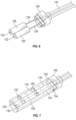
- the housing 102 contains a number of internal components which are described herein and illustrated in at least FIGS. 5-9 .
- an outer tube 110 containing fibers and a cooling passage is shown extending from an aft end 112 of the housing 102.
- a view window 114 is defined proximate the forward end 116 of the housing 102.
- Disposed near or within the view window 114 is a portion of an optical head 118 and a mirror 120.
- the position of the optical head 118 is fixed with an optics head retention pin 122 and the position of the mirror 120 is fixed with a mirror retention pin 124.
- Each pin 122, 124 extends through the housing 102 to secure the optical head 118 and the mirror 120, respectively, to the housing 102.
- fiber holders 136 holding optical fibers 134.
- One of the optical fibers is a transmit fiber to route light from a laser source and the other fiber is a receive fiber to route light to a photo detector.
- Disposed at an end of each fiber holder 136 is an optical lens 132.
- An adhesive is used to hold the optical lenses 132, fiber holders 136, and optical fibers 134 in place.
- the optical fibers 134 may be coated in a high temperature material to withstand temperatures up to 1300 degrees Fahrenheit (700 degrees Celcius), making high temperature uncooled optical probe employable in every stage of high pressure compressors and low pressure compressors of a gas turbine engine.
- the optical fibers proximate the lens 132 are polished to have a flush surface with the end of the fiber holders 136.
- the optical lens 132 may be convex or may be a gradient index of refraction (GRIN) lens.
- the optical lenses 132 may be made of a transparent material, such as sapphire or silica. As a result, high temperature optical lenses 132 may withstand temperatures of up to 2000 degrees Fahrenheit (1100 degrees Celcius). In one embodiment, the optical lens 132 collimates the light from the fiber 134.
- the fiber holders 136 may be made of a superalloy, such as Incoloy ® . In alternative embodiments, the fiber holders 136 may be made of an alloy or a superalloy, such as Haynes ® 242 ® or Waspaloy ® .
- the adhesive used to hold the optical lenses 132, fiber holders 134, and optical fibers 134 in place may be a high temperature adhesive, such as a Cotronics Resbond 907TS variant, which can withstand temperatures of up to 2200 degrees Fahrenheit (1204 degrees Celcius).
- the optical fibers 134 are routed through respective channels of a cap 140.
- the cap 140 provides a connection between an inner tube 142 that houses an aft portion the optical fibers 134, while also providing integrated channels for cooling and/or purging of the interior of the housing 102.
- the cap 140 is brazed to the inner tube 142 and then slid over the fibers 134 during assembly.
- the optical head 118 includes through holes 150 extending axially in a longitudinal direction of the optical head 118.
- the optical lenses 132 and the fiber holders 136 are inserted into an aft side 152 of the optical head 118 and the cap 140 is welded to the aft side 152.
- a pocket 154 or other location feature of the optical head 118 at the aft side 152 provides a feature to assist with proper locating of the cap 140 relative to the optical head 118.
- Multiple holes 156 are provided along optical head 118 to allow for the optical lenses 132 and the fiber holders 136 to be glued into place within the optical head 118.
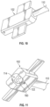
- FIGS. 10-12 illustrate the optical head 118 and the cap 140 disposed within the housing 102.
- the optical head 118 is inserted and slid into the housing 102 to place the forward end 160 of the optical head 118 within the view window 114.
- the optics head retention pin 122 or a similar mechanical fastener is inserted through the housing 102 and into the optical head 118 to fix the position of the optical head 118.
- the inner tube 142 is also shown in FIG. 12 to be at least partially inserted into the housing 102.
- the outer tube 110 is placed concentrically around the inner tube 142 and brazed to the housing 102.
- the inner tube 142 and the outer tube 110 are radially spaced from each other to define an annulus 164 that allows for cooling air to be routed therethrough or to purge the interior of the housing 102.
- the mirror 120 is installed at a forward end 170 of the housing 102 in a desired position.
- the mirror retention pin 124 or a similar mechanical fastener is inserted through the housing 102 and into the mirror 120 to fix the position of the mirror 120.
- the optical fibers are electrically connected to a measurement device 200, as shown in FIG. 14 .
- the measurement device 200 is configured to determine various vibratory modes.
- the measurement device 200 may include a processor and a memory.
- the processor can be any type or combination of computer processors, such as a microprocessor, microcontroller, digital signal processor, application specific integrated circuit, programmable logic device, and/or field programmable gate array.
- the memory is an example of a non-transitory computer readable storage medium tangibly embodied in or operably connected to the path determination system including executable instructions stored therein, for instance, as firmware.
- the transmit fiber is optically connected to a laser source controlled at the measurement device 200.
- the receive fiber is optically connected to a photo-detector which is electrically connected to the measurement device 200.
- the embodiments described herein provides a probe that can be fully embedded in the radial flow separation wall 72 to collect NSMS data without any impact to the BOM hardware.
Landscapes
- Engineering & Computer Science (AREA)
- Physics & Mathematics (AREA)
- General Physics & Mathematics (AREA)
- Mechanical Engineering (AREA)
- General Engineering & Computer Science (AREA)
- Chemical & Material Sciences (AREA)
- Combustion & Propulsion (AREA)
- Turbine Rotor Nozzle Sealing (AREA)
Claims (11)
- Optische Sonde (100) für ein Gasturbinentriebwerk (20), umfassend:ein Gehäuse (102);eine Vielzahl von optischen Fasern (134), wobei ein Abschnitt jeder der optischen Fasern an Faserhaltern (136) befestigt ist;einen optischen Kopf (118), der innerhalb des Gehäuses angeordnet ist und Kanäle aufweist, die in einer Längsrichtung des optischen Kopfs verlaufen, wobei die Faserhalter innerhalb der Kanäle angeordnet sind;eine Kappe (140), die innerhalb des Gehäuses angeordnet und betriebsmäßig mit dem optischen Kopf gekoppelt ist, wobei die Vielzahl von optischen Fasern durch die Kappe verläuft; undein Innenrohr (142), das betriebsmäßig mit der Kappe verbunden ist, wobei die Vielzahl von Fasern durch das Innenrohr verläuft; undein Außenrohr (110), das einen Abschnitt des Innenrohrs umgibt, wobei das Innenrohr und das Außenrohr radial voneinander beabstandet sind, um dazwischen einen Ringraum (164) zu definieren, der derart angeordnet ist, dass Kühlluft hindurchgeleitet werden kann oder der Innenraum des Gehäuses gespült werden kann, wobei das Außenrohr betriebsmäßig mit dem Gehäuse verbunden ist.
- Optische Sonde nach Anspruch 1, wobei das Außenrohr mit dem Gehäuse (102) verlötet ist.
- Optische Sonde nach Anspruch 1 oder 2, wobei eine axiale Position des optischen Kopfs (118) mit einem optischen Kopfhaltestift (122) fixiert ist, der durch das Gehäuse (102) und in den optischen Kopf (118) verläuft.
- Optische Sonde nach einem der vorhergehenden Ansprüche, wobei der optische Kopf eine Vielzahl von Löchern nahe der Faserhalter definiert, um die Faserhalter (136) mit einem Klebstoff daran zu befestigen.
- Optische Sonde nach einem der vorhergehenden Ansprüche, wobei ein vorderes Ende des optischen Kopfes innerhalb eines Sichtfensters angeordnet ist, das durch das Gehäuse (102) definiert ist, optional ferner einen Spiegel (120) umfasst, der innerhalb des Sichtfensters (114) operativ mit dem Gehäuse (102) gekoppelt ist, wobei optional der Spiegel operativ mit dem Gehäuse (102) gekoppelt ist, wobei ein Spiegelhaltestift (124) durch das Gehäuse und in den Spiegel verläuft.
- Optische Sonde nach einem der vorhergehenden Ansprüche, wobei die Kappe (140) an den optischen Kopf (118) geschweißt ist.
- Optische Sonde nach einem der Ansprüche 1 bis 5, wobei die Kappe (140) an das Innenrohr (142) gelötet ist.
- Optische Sonde nach einem der vorhergehenden Ansprüche, wobei die Kappe Kanäle zur Fluidkopplung des durch das Innen- und das Außenrohr definierten Ringraums mit dem Innenraum des optischen Kopfes einschließt.
- Gasturbinentriebwerk, umfassend:eine Strömungstrennwand (72), die einen ersten Strömungsweg (FP1) von einem zweiten Strömungsweg (FP2) trennt; undeine optische Sonde (100) gemäß einem der vorhergehenden Ansprüche, die in die Strömungstrennwand eingebettet ist.
- Gasturbinentriebwerk nach Anspruch 9, wobei das Gehäuse mindestens einen Flansch (106) und einen Hauptkörperabschnitt (104) einschließt, wobei der Hauptkörperabschnitt einen Innenraum des Gehäuses definiert, wobei optional der mindestens eine Flansch an die Strömungstrennwand geschweißt ist.
- Gasturbinentriebwerk nach Anspruch 9 oder 10, wobei die optische Sonde (100) vollständig in die Strömungstrennwand (72) eingebettet ist.
Applications Claiming Priority (1)
| Application Number | Priority Date | Filing Date | Title |
|---|---|---|---|
| US15/932,263 US10768059B2 (en) | 2018-02-16 | 2018-02-16 | Embedded optical probe for gas turbine engine |
Publications (2)
| Publication Number | Publication Date |
|---|---|
| EP3527787A1 EP3527787A1 (de) | 2019-08-21 |
| EP3527787B1 true EP3527787B1 (de) | 2024-10-02 |
Family
ID=64665730
Family Applications (1)
| Application Number | Title | Priority Date | Filing Date |
|---|---|---|---|
| EP18212795.1A Active EP3527787B1 (de) | 2018-02-16 | 2018-12-14 | Eingebettete optische sonde für gasturbinenmotor |
Country Status (2)
| Country | Link |
|---|---|
| US (1) | US10768059B2 (de) |
| EP (1) | EP3527787B1 (de) |
Families Citing this family (4)
| Publication number | Priority date | Publication date | Assignee | Title |
|---|---|---|---|---|
| US11513034B2 (en) | 2020-02-14 | 2022-11-29 | Raytheon Technologies Corporation | Probe adapter for a blade outer air seal and method for using same |
| US12455213B2 (en) * | 2023-02-01 | 2025-10-28 | Rtx Corporation | Measurement system having a capacitance probe and an optical probe |
| US12553796B2 (en) * | 2023-03-14 | 2026-02-17 | Rtx Corporation | Measurement system having a probe for measuring parameters of a turbine engine |
| US12487425B2 (en) | 2023-03-21 | 2025-12-02 | Rtx Corporation | Coupling optical fibers and cooling fluid passages |
Family Cites Families (13)
| Publication number | Priority date | Publication date | Assignee | Title |
|---|---|---|---|---|
| US5277496A (en) * | 1990-10-17 | 1994-01-11 | Ametek, Inc. | High temperature optical probe |
| US5201227A (en) * | 1992-03-05 | 1993-04-13 | Ishikawajima-Harima Jukogyo Kabushiki Kaisha | Device for measuring vibrations on rotating blade |
| US7966834B2 (en) | 2004-05-07 | 2011-06-28 | Rosemount Aerospace Inc. | Apparatus for observing combustion conditions in a gas turbine engine |
| GB2494703B (en) * | 2011-09-16 | 2016-08-03 | Weston Aerospace Ltd | System and method for detecting abnormal movement in a gas turbine shaft |
| US8687206B2 (en) | 2012-05-29 | 2014-04-01 | United Technologies Corporation | Optical detection of airfoil axial position with NSMS |
| US9181818B2 (en) * | 2012-09-25 | 2015-11-10 | United Technologies Corporation | Thermally constrained high temperature optical fiber holder |
| US9188463B2 (en) * | 2013-02-05 | 2015-11-17 | General Electric Company | Hermetic electrically shielded connector |
| US9366586B2 (en) | 2013-03-14 | 2016-06-14 | United Technologies Corporation | High temperature uncooled optical probe |
| US9404735B2 (en) * | 2013-03-15 | 2016-08-02 | United Technologies Corporation | Multiple laser time of arrival probe |
| EP2789914A1 (de) * | 2013-04-12 | 2014-10-15 | Siemens Aktiengesellschaft | Verfahren zur Überwachung eines Flammenzustands |
| US9530209B2 (en) * | 2014-01-15 | 2016-12-27 | Siemens Energy, Inc. | Method of determining the location of tip timing sensors during operation |
| US9714967B1 (en) * | 2016-01-27 | 2017-07-25 | General Electric Company | Electrostatic dust and debris sensor for an engine |
| US10775269B2 (en) * | 2017-02-08 | 2020-09-15 | Raytheon Technologies Corporation | Blade health inspection using an excitation actuator and vibration sensor |
-
2018
- 2018-02-16 US US15/932,263 patent/US10768059B2/en active Active
- 2018-12-14 EP EP18212795.1A patent/EP3527787B1/de active Active
Also Published As
| Publication number | Publication date |
|---|---|
| EP3527787A1 (de) | 2019-08-21 |
| US20190257705A1 (en) | 2019-08-22 |
| US10768059B2 (en) | 2020-09-08 |
Similar Documents
| Publication | Publication Date | Title |
|---|---|---|
| EP3527787B1 (de) | Eingebettete optische sonde für gasturbinenmotor | |
| EP0296058B1 (de) | Aussengehäuse einer Turbinenbrennkammer mit Öffnungen zur Luftentnahme | |
| US11111813B2 (en) | Gas turbine engine maintenance method | |
| US11067002B2 (en) | Gas turbine engine maintenance tool | |
| EP3580433B1 (de) | Drucksensoranordnung für einen turbinenmotor | |
| KR101815434B1 (ko) | 광학 요소를 수납하기 위해서 분리가능한 튜브 섹션을 갖춘 내부 튜브를 갖는 광학 탐침에 관한 방법들 | |
| US11175187B2 (en) | Air temperature sensor having a bushing | |
| EP3048250B1 (de) | Kühlsystem mit überkühlter luft mit ringförmigem mischkanal | |
| EP3628926B1 (de) | Sensoranordnung zur messung von gasturbinenbrennkammertemperaturen | |
| KR101905433B1 (ko) | 광학 요소를 수납하기 위해서 분리가능한 튜브 섹션을 갖춘 내부 튜브를 갖는 광학 탐침 | |
| US9952066B2 (en) | Thermally constrained high temperature optical fiber holder | |
| US20160303693A1 (en) | Gas turbine engine components and method of assembly | |
| US11624662B2 (en) | Exhaust gas temperature sensor | |
| US11946811B2 (en) | Non-contact high temperature measurement system | |
| EP3712503B1 (de) | Auskleidung für eine gasturbinenbrennkammer | |
| US10941669B2 (en) | Diffuser case support structure | |
| US9518895B2 (en) | Optical probe with improved affixing structure for supporting a light-redirecting element |
Legal Events
| Date | Code | Title | Description |
|---|---|---|---|
| PUAI | Public reference made under article 153(3) epc to a published international application that has entered the european phase |
Free format text: ORIGINAL CODE: 0009012 |
|
| STAA | Information on the status of an ep patent application or granted ep patent |
Free format text: STATUS: THE APPLICATION HAS BEEN PUBLISHED |
|
| AK | Designated contracting states |
Kind code of ref document: A1 Designated state(s): AL AT BE BG CH CY CZ DE DK EE ES FI FR GB GR HR HU IE IS IT LI LT LU LV MC MK MT NL NO PL PT RO RS SE SI SK SM TR |
|
| AX | Request for extension of the european patent |
Extension state: BA ME |
|
| STAA | Information on the status of an ep patent application or granted ep patent |
Free format text: STATUS: REQUEST FOR EXAMINATION WAS MADE |
|
| 17P | Request for examination filed |
Effective date: 20200214 |
|
| RBV | Designated contracting states (corrected) |
Designated state(s): AL AT BE BG CH CY CZ DE DK EE ES FI FR GB GR HR HU IE IS IT LI LT LU LV MC MK MT NL NO PL PT RO RS SE SI SK SM TR |
|
| RAP1 | Party data changed (applicant data changed or rights of an application transferred) |
Owner name: RAYTHEON TECHNOLOGIES CORPORATION |
|
| STAA | Information on the status of an ep patent application or granted ep patent |
Free format text: STATUS: EXAMINATION IS IN PROGRESS |
|
| 17Q | First examination report despatched |
Effective date: 20220315 |
|
| RAP3 | Party data changed (applicant data changed or rights of an application transferred) |
Owner name: RTX CORPORATION |
|
| GRAP | Despatch of communication of intention to grant a patent |
Free format text: ORIGINAL CODE: EPIDOSNIGR1 |
|
| STAA | Information on the status of an ep patent application or granted ep patent |
Free format text: STATUS: GRANT OF PATENT IS INTENDED |
|
| INTG | Intention to grant announced |
Effective date: 20240424 |
|
| GRAS | Grant fee paid |
Free format text: ORIGINAL CODE: EPIDOSNIGR3 |
|
| GRAA | (expected) grant |
Free format text: ORIGINAL CODE: 0009210 |
|
| STAA | Information on the status of an ep patent application or granted ep patent |
Free format text: STATUS: THE PATENT HAS BEEN GRANTED |
|
| AK | Designated contracting states |
Kind code of ref document: B1 Designated state(s): AL AT BE BG CH CY CZ DE DK EE ES FI FR GB GR HR HU IE IS IT LI LT LU LV MC MK MT NL NO PL PT RO RS SE SI SK SM TR |
|
| REG | Reference to a national code |
Ref country code: GB Ref legal event code: FG4D |
|
| REG | Reference to a national code |
Ref country code: CH Ref legal event code: EP |
|
| REG | Reference to a national code |
Ref country code: IE Ref legal event code: FG4D |
|
| REG | Reference to a national code |
Ref country code: DE Ref legal event code: R096 Ref document number: 602018074902 Country of ref document: DE |
|
| REG | Reference to a national code |
Ref country code: LT Ref legal event code: MG9D |
|
| REG | Reference to a national code |
Ref country code: NL Ref legal event code: MP Effective date: 20241002 |
|
| REG | Reference to a national code |
Ref country code: AT Ref legal event code: MK05 Ref document number: 1728657 Country of ref document: AT Kind code of ref document: T Effective date: 20241002 |
|
| PG25 | Lapsed in a contracting state [announced via postgrant information from national office to epo] |
Ref country code: NL Free format text: LAPSE BECAUSE OF FAILURE TO SUBMIT A TRANSLATION OF THE DESCRIPTION OR TO PAY THE FEE WITHIN THE PRESCRIBED TIME-LIMIT Effective date: 20241002 |
|
| PG25 | Lapsed in a contracting state [announced via postgrant information from national office to epo] |
Ref country code: NL Free format text: LAPSE BECAUSE OF FAILURE TO SUBMIT A TRANSLATION OF THE DESCRIPTION OR TO PAY THE FEE WITHIN THE PRESCRIBED TIME-LIMIT Effective date: 20241002 |
|
| PG25 | Lapsed in a contracting state [announced via postgrant information from national office to epo] |
Ref country code: PT Free format text: LAPSE BECAUSE OF FAILURE TO SUBMIT A TRANSLATION OF THE DESCRIPTION OR TO PAY THE FEE WITHIN THE PRESCRIBED TIME-LIMIT Effective date: 20250203 Ref country code: IS Free format text: LAPSE BECAUSE OF FAILURE TO SUBMIT A TRANSLATION OF THE DESCRIPTION OR TO PAY THE FEE WITHIN THE PRESCRIBED TIME-LIMIT Effective date: 20250202 Ref country code: HR Free format text: LAPSE BECAUSE OF FAILURE TO SUBMIT A TRANSLATION OF THE DESCRIPTION OR TO PAY THE FEE WITHIN THE PRESCRIBED TIME-LIMIT Effective date: 20241002 |
|
| PG25 | Lapsed in a contracting state [announced via postgrant information from national office to epo] |
Ref country code: FI Free format text: LAPSE BECAUSE OF FAILURE TO SUBMIT A TRANSLATION OF THE DESCRIPTION OR TO PAY THE FEE WITHIN THE PRESCRIBED TIME-LIMIT Effective date: 20241002 |
|
| PG25 | Lapsed in a contracting state [announced via postgrant information from national office to epo] |
Ref country code: BG Free format text: LAPSE BECAUSE OF FAILURE TO SUBMIT A TRANSLATION OF THE DESCRIPTION OR TO PAY THE FEE WITHIN THE PRESCRIBED TIME-LIMIT Effective date: 20241002 |
|
| PG25 | Lapsed in a contracting state [announced via postgrant information from national office to epo] |
Ref country code: ES Free format text: LAPSE BECAUSE OF FAILURE TO SUBMIT A TRANSLATION OF THE DESCRIPTION OR TO PAY THE FEE WITHIN THE PRESCRIBED TIME-LIMIT Effective date: 20241002 |
|
| PG25 | Lapsed in a contracting state [announced via postgrant information from national office to epo] |
Ref country code: NO Free format text: LAPSE BECAUSE OF FAILURE TO SUBMIT A TRANSLATION OF THE DESCRIPTION OR TO PAY THE FEE WITHIN THE PRESCRIBED TIME-LIMIT Effective date: 20250102 |
|
| PG25 | Lapsed in a contracting state [announced via postgrant information from national office to epo] |
Ref country code: AT Free format text: LAPSE BECAUSE OF FAILURE TO SUBMIT A TRANSLATION OF THE DESCRIPTION OR TO PAY THE FEE WITHIN THE PRESCRIBED TIME-LIMIT Effective date: 20241002 Ref country code: LV Free format text: LAPSE BECAUSE OF FAILURE TO SUBMIT A TRANSLATION OF THE DESCRIPTION OR TO PAY THE FEE WITHIN THE PRESCRIBED TIME-LIMIT Effective date: 20241002 Ref country code: GR Free format text: LAPSE BECAUSE OF FAILURE TO SUBMIT A TRANSLATION OF THE DESCRIPTION OR TO PAY THE FEE WITHIN THE PRESCRIBED TIME-LIMIT Effective date: 20250103 |
|
| PG25 | Lapsed in a contracting state [announced via postgrant information from national office to epo] |
Ref country code: CZ Free format text: LAPSE BECAUSE OF FAILURE TO SUBMIT A TRANSLATION OF THE DESCRIPTION OR TO PAY THE FEE WITHIN THE PRESCRIBED TIME-LIMIT Effective date: 20241002 Ref country code: PL Free format text: LAPSE BECAUSE OF FAILURE TO SUBMIT A TRANSLATION OF THE DESCRIPTION OR TO PAY THE FEE WITHIN THE PRESCRIBED TIME-LIMIT Effective date: 20241002 |
|
| PG25 | Lapsed in a contracting state [announced via postgrant information from national office to epo] |
Ref country code: RS Free format text: LAPSE BECAUSE OF FAILURE TO SUBMIT A TRANSLATION OF THE DESCRIPTION OR TO PAY THE FEE WITHIN THE PRESCRIBED TIME-LIMIT Effective date: 20250102 |
|
| PG25 | Lapsed in a contracting state [announced via postgrant information from national office to epo] |
Ref country code: SM Free format text: LAPSE BECAUSE OF FAILURE TO SUBMIT A TRANSLATION OF THE DESCRIPTION OR TO PAY THE FEE WITHIN THE PRESCRIBED TIME-LIMIT Effective date: 20241002 |
|
| REG | Reference to a national code |
Ref country code: DE Ref legal event code: R097 Ref document number: 602018074902 Country of ref document: DE |
|
| PG25 | Lapsed in a contracting state [announced via postgrant information from national office to epo] |
Ref country code: MC Free format text: LAPSE BECAUSE OF FAILURE TO SUBMIT A TRANSLATION OF THE DESCRIPTION OR TO PAY THE FEE WITHIN THE PRESCRIBED TIME-LIMIT Effective date: 20241002 |
|
| PG25 | Lapsed in a contracting state [announced via postgrant information from national office to epo] |
Ref country code: DK Free format text: LAPSE BECAUSE OF FAILURE TO SUBMIT A TRANSLATION OF THE DESCRIPTION OR TO PAY THE FEE WITHIN THE PRESCRIBED TIME-LIMIT Effective date: 20241002 |
|
| PG25 | Lapsed in a contracting state [announced via postgrant information from national office to epo] |
Ref country code: EE Free format text: LAPSE BECAUSE OF FAILURE TO SUBMIT A TRANSLATION OF THE DESCRIPTION OR TO PAY THE FEE WITHIN THE PRESCRIBED TIME-LIMIT Effective date: 20241002 |
|
| PG25 | Lapsed in a contracting state [announced via postgrant information from national office to epo] |
Ref country code: RO Free format text: LAPSE BECAUSE OF FAILURE TO SUBMIT A TRANSLATION OF THE DESCRIPTION OR TO PAY THE FEE WITHIN THE PRESCRIBED TIME-LIMIT Effective date: 20241002 |
|
| PG25 | Lapsed in a contracting state [announced via postgrant information from national office to epo] |
Ref country code: SK Free format text: LAPSE BECAUSE OF FAILURE TO SUBMIT A TRANSLATION OF THE DESCRIPTION OR TO PAY THE FEE WITHIN THE PRESCRIBED TIME-LIMIT Effective date: 20241002 |
|
| PG25 | Lapsed in a contracting state [announced via postgrant information from national office to epo] |
Ref country code: IT Free format text: LAPSE BECAUSE OF FAILURE TO SUBMIT A TRANSLATION OF THE DESCRIPTION OR TO PAY THE FEE WITHIN THE PRESCRIBED TIME-LIMIT Effective date: 20241002 |
|
| REG | Reference to a national code |
Ref country code: CH Ref legal event code: PL |
|
| PLBE | No opposition filed within time limit |
Free format text: ORIGINAL CODE: 0009261 |
|
| STAA | Information on the status of an ep patent application or granted ep patent |
Free format text: STATUS: NO OPPOSITION FILED WITHIN TIME LIMIT |
|
| PG25 | Lapsed in a contracting state [announced via postgrant information from national office to epo] |
Ref country code: LU Free format text: LAPSE BECAUSE OF NON-PAYMENT OF DUE FEES Effective date: 20241214 |
|
| PG25 | Lapsed in a contracting state [announced via postgrant information from national office to epo] |
Ref country code: SE Free format text: LAPSE BECAUSE OF FAILURE TO SUBMIT A TRANSLATION OF THE DESCRIPTION OR TO PAY THE FEE WITHIN THE PRESCRIBED TIME-LIMIT Effective date: 20241002 |
|
| 26N | No opposition filed |
Effective date: 20250703 |
|
| REG | Reference to a national code |
Ref country code: BE Ref legal event code: MM Effective date: 20241231 |
|
| PG25 | Lapsed in a contracting state [announced via postgrant information from national office to epo] |
Ref country code: BE Free format text: LAPSE BECAUSE OF NON-PAYMENT OF DUE FEES Effective date: 20241231 |
|
| PG25 | Lapsed in a contracting state [announced via postgrant information from national office to epo] |
Ref country code: CH Free format text: LAPSE BECAUSE OF NON-PAYMENT OF DUE FEES Effective date: 20241231 |
|
| PG25 | Lapsed in a contracting state [announced via postgrant information from national office to epo] |
Ref country code: IE Free format text: LAPSE BECAUSE OF NON-PAYMENT OF DUE FEES Effective date: 20241214 |
|
| PGFP | Annual fee paid to national office [announced via postgrant information from national office to epo] |
Ref country code: DE Payment date: 20251126 Year of fee payment: 8 |
|
| PGFP | Annual fee paid to national office [announced via postgrant information from national office to epo] |
Ref country code: GB Payment date: 20251119 Year of fee payment: 8 |
|
| PGFP | Annual fee paid to national office [announced via postgrant information from national office to epo] |
Ref country code: FR Payment date: 20251119 Year of fee payment: 8 |