EP3527726A1 - Device for the production of water on board a vehicle and method to control said device - Google Patents
Device for the production of water on board a vehicle and method to control said device Download PDFInfo
- Publication number
- EP3527726A1 EP3527726A1 EP19156987.0A EP19156987A EP3527726A1 EP 3527726 A1 EP3527726 A1 EP 3527726A1 EP 19156987 A EP19156987 A EP 19156987A EP 3527726 A1 EP3527726 A1 EP 3527726A1
- Authority
- EP
- European Patent Office
- Prior art keywords
- tank
- air flow
- adsorbing material
- water
- duct
- Prior art date
- Legal status (The legal status is an assumption and is not a legal conclusion. Google has not performed a legal analysis and makes no representation as to the accuracy of the status listed.)
- Withdrawn
Links
Images
Classifications
-
- B—PERFORMING OPERATIONS; TRANSPORTING
- B01—PHYSICAL OR CHEMICAL PROCESSES OR APPARATUS IN GENERAL
- B01D—SEPARATION
- B01D53/00—Separation of gases or vapours; Recovering vapours of volatile solvents from gases; Chemical or biological purification of waste gases, e.g. engine exhaust gases, smoke, fumes, flue gases, aerosols
- B01D53/26—Drying gases or vapours
- B01D53/261—Drying gases or vapours by adsorption
-
- B—PERFORMING OPERATIONS; TRANSPORTING
- B01—PHYSICAL OR CHEMICAL PROCESSES OR APPARATUS IN GENERAL
- B01D—SEPARATION
- B01D53/00—Separation of gases or vapours; Recovering vapours of volatile solvents from gases; Chemical or biological purification of waste gases, e.g. engine exhaust gases, smoke, fumes, flue gases, aerosols
- B01D53/02—Separation of gases or vapours; Recovering vapours of volatile solvents from gases; Chemical or biological purification of waste gases, e.g. engine exhaust gases, smoke, fumes, flue gases, aerosols by adsorption, e.g. preparative gas chromatography
- B01D53/04—Separation of gases or vapours; Recovering vapours of volatile solvents from gases; Chemical or biological purification of waste gases, e.g. engine exhaust gases, smoke, fumes, flue gases, aerosols by adsorption, e.g. preparative gas chromatography with stationary adsorbents
- B01D53/0407—Constructional details of adsorbing systems
- B01D53/0438—Cooling or heating systems
-
- B—PERFORMING OPERATIONS; TRANSPORTING
- B01—PHYSICAL OR CHEMICAL PROCESSES OR APPARATUS IN GENERAL
- B01D—SEPARATION
- B01D53/00—Separation of gases or vapours; Recovering vapours of volatile solvents from gases; Chemical or biological purification of waste gases, e.g. engine exhaust gases, smoke, fumes, flue gases, aerosols
- B01D53/02—Separation of gases or vapours; Recovering vapours of volatile solvents from gases; Chemical or biological purification of waste gases, e.g. engine exhaust gases, smoke, fumes, flue gases, aerosols by adsorption, e.g. preparative gas chromatography
- B01D53/04—Separation of gases or vapours; Recovering vapours of volatile solvents from gases; Chemical or biological purification of waste gases, e.g. engine exhaust gases, smoke, fumes, flue gases, aerosols by adsorption, e.g. preparative gas chromatography with stationary adsorbents
- B01D53/0407—Constructional details of adsorbing systems
- B01D53/0446—Means for feeding or distributing gases
-
- B—PERFORMING OPERATIONS; TRANSPORTING
- B01—PHYSICAL OR CHEMICAL PROCESSES OR APPARATUS IN GENERAL
- B01D—SEPARATION
- B01D53/00—Separation of gases or vapours; Recovering vapours of volatile solvents from gases; Chemical or biological purification of waste gases, e.g. engine exhaust gases, smoke, fumes, flue gases, aerosols
- B01D53/02—Separation of gases or vapours; Recovering vapours of volatile solvents from gases; Chemical or biological purification of waste gases, e.g. engine exhaust gases, smoke, fumes, flue gases, aerosols by adsorption, e.g. preparative gas chromatography
- B01D53/04—Separation of gases or vapours; Recovering vapours of volatile solvents from gases; Chemical or biological purification of waste gases, e.g. engine exhaust gases, smoke, fumes, flue gases, aerosols by adsorption, e.g. preparative gas chromatography with stationary adsorbents
- B01D53/0454—Controlling adsorption
-
- B—PERFORMING OPERATIONS; TRANSPORTING
- B01—PHYSICAL OR CHEMICAL PROCESSES OR APPARATUS IN GENERAL
- B01D—SEPARATION
- B01D53/00—Separation of gases or vapours; Recovering vapours of volatile solvents from gases; Chemical or biological purification of waste gases, e.g. engine exhaust gases, smoke, fumes, flue gases, aerosols
- B01D53/02—Separation of gases or vapours; Recovering vapours of volatile solvents from gases; Chemical or biological purification of waste gases, e.g. engine exhaust gases, smoke, fumes, flue gases, aerosols by adsorption, e.g. preparative gas chromatography
- B01D53/04—Separation of gases or vapours; Recovering vapours of volatile solvents from gases; Chemical or biological purification of waste gases, e.g. engine exhaust gases, smoke, fumes, flue gases, aerosols by adsorption, e.g. preparative gas chromatography with stationary adsorbents
- B01D53/0462—Temperature swing adsorption
-
- B—PERFORMING OPERATIONS; TRANSPORTING
- B01—PHYSICAL OR CHEMICAL PROCESSES OR APPARATUS IN GENERAL
- B01D—SEPARATION
- B01D53/00—Separation of gases or vapours; Recovering vapours of volatile solvents from gases; Chemical or biological purification of waste gases, e.g. engine exhaust gases, smoke, fumes, flue gases, aerosols
- B01D53/30—Controlling by gas-analysis apparatus
-
- B—PERFORMING OPERATIONS; TRANSPORTING
- B60—VEHICLES IN GENERAL
- B60K—ARRANGEMENT OR MOUNTING OF PROPULSION UNITS OR OF TRANSMISSIONS IN VEHICLES; ARRANGEMENT OR MOUNTING OF PLURAL DIVERSE PRIME-MOVERS IN VEHICLES; AUXILIARY DRIVES FOR VEHICLES; INSTRUMENTATION OR DASHBOARDS FOR VEHICLES; ARRANGEMENTS IN CONNECTION WITH COOLING, AIR INTAKE, GAS EXHAUST OR FUEL SUPPLY OF PROPULSION UNITS IN VEHICLES
- B60K11/00—Arrangement in connection with cooling of propulsion units
- B60K11/02—Arrangement in connection with cooling of propulsion units with liquid cooling
-
- E—FIXED CONSTRUCTIONS
- E03—WATER SUPPLY; SEWERAGE
- E03B—INSTALLATIONS OR METHODS FOR OBTAINING, COLLECTING, OR DISTRIBUTING WATER
- E03B3/00—Methods or installations for obtaining or collecting drinking water or tap water
- E03B3/28—Methods or installations for obtaining or collecting drinking water or tap water from humid air
-
- F—MECHANICAL ENGINEERING; LIGHTING; HEATING; WEAPONS; BLASTING
- F01—MACHINES OR ENGINES IN GENERAL; ENGINE PLANTS IN GENERAL; STEAM ENGINES
- F01N—GAS-FLOW SILENCERS OR EXHAUST APPARATUS FOR MACHINES OR ENGINES IN GENERAL; GAS-FLOW SILENCERS OR EXHAUST APPARATUS FOR INTERNAL-COMBUSTION ENGINES
- F01N3/00—Exhaust or silencing apparatus having means for purifying, rendering innocuous, or otherwise treating exhaust
- F01N3/08—Exhaust or silencing apparatus having means for purifying, rendering innocuous, or otherwise treating exhaust for rendering innocuous
- F01N3/0807—Exhaust or silencing apparatus having means for purifying, rendering innocuous, or otherwise treating exhaust for rendering innocuous by using absorbents or adsorbents
- F01N3/0828—Exhaust or silencing apparatus having means for purifying, rendering innocuous, or otherwise treating exhaust for rendering innocuous by using absorbents or adsorbents characterised by the absorbed or adsorbed substances
-
- F—MECHANICAL ENGINEERING; LIGHTING; HEATING; WEAPONS; BLASTING
- F01—MACHINES OR ENGINES IN GENERAL; ENGINE PLANTS IN GENERAL; STEAM ENGINES
- F01N—GAS-FLOW SILENCERS OR EXHAUST APPARATUS FOR MACHINES OR ENGINES IN GENERAL; GAS-FLOW SILENCERS OR EXHAUST APPARATUS FOR INTERNAL-COMBUSTION ENGINES
- F01N3/00—Exhaust or silencing apparatus having means for purifying, rendering innocuous, or otherwise treating exhaust
- F01N3/08—Exhaust or silencing apparatus having means for purifying, rendering innocuous, or otherwise treating exhaust for rendering innocuous
- F01N3/0807—Exhaust or silencing apparatus having means for purifying, rendering innocuous, or otherwise treating exhaust for rendering innocuous by using absorbents or adsorbents
- F01N3/0871—Exhaust or silencing apparatus having means for purifying, rendering innocuous, or otherwise treating exhaust for rendering innocuous by using absorbents or adsorbents using means for controlling, e.g. purging, the absorbents or adsorbents
-
- F—MECHANICAL ENGINEERING; LIGHTING; HEATING; WEAPONS; BLASTING
- F01—MACHINES OR ENGINES IN GENERAL; ENGINE PLANTS IN GENERAL; STEAM ENGINES
- F01N—GAS-FLOW SILENCERS OR EXHAUST APPARATUS FOR MACHINES OR ENGINES IN GENERAL; GAS-FLOW SILENCERS OR EXHAUST APPARATUS FOR INTERNAL-COMBUSTION ENGINES
- F01N3/00—Exhaust or silencing apparatus having means for purifying, rendering innocuous, or otherwise treating exhaust
- F01N3/08—Exhaust or silencing apparatus having means for purifying, rendering innocuous, or otherwise treating exhaust for rendering innocuous
- F01N3/10—Exhaust or silencing apparatus having means for purifying, rendering innocuous, or otherwise treating exhaust for rendering innocuous by thermal or catalytic conversion of noxious components of exhaust
- F01N3/18—Exhaust or silencing apparatus having means for purifying, rendering innocuous, or otherwise treating exhaust for rendering innocuous by thermal or catalytic conversion of noxious components of exhaust characterised by methods of operation; Control
- F01N3/20—Exhaust or silencing apparatus having means for purifying, rendering innocuous, or otherwise treating exhaust for rendering innocuous by thermal or catalytic conversion of noxious components of exhaust characterised by methods of operation; Control specially adapted for catalytic conversion
- F01N3/206—Adding periodically or continuously substances to exhaust gases for promoting purification, e.g. catalytic material in liquid form, NOx reducing agents
- F01N3/2066—Selective catalytic reduction [SCR]
-
- F—MECHANICAL ENGINEERING; LIGHTING; HEATING; WEAPONS; BLASTING
- F01—MACHINES OR ENGINES IN GENERAL; ENGINE PLANTS IN GENERAL; STEAM ENGINES
- F01N—GAS-FLOW SILENCERS OR EXHAUST APPARATUS FOR MACHINES OR ENGINES IN GENERAL; GAS-FLOW SILENCERS OR EXHAUST APPARATUS FOR INTERNAL-COMBUSTION ENGINES
- F01N3/00—Exhaust or silencing apparatus having means for purifying, rendering innocuous, or otherwise treating exhaust
- F01N3/08—Exhaust or silencing apparatus having means for purifying, rendering innocuous, or otherwise treating exhaust for rendering innocuous
- F01N3/10—Exhaust or silencing apparatus having means for purifying, rendering innocuous, or otherwise treating exhaust for rendering innocuous by thermal or catalytic conversion of noxious components of exhaust
- F01N3/18—Exhaust or silencing apparatus having means for purifying, rendering innocuous, or otherwise treating exhaust for rendering innocuous by thermal or catalytic conversion of noxious components of exhaust characterised by methods of operation; Control
- F01N3/20—Exhaust or silencing apparatus having means for purifying, rendering innocuous, or otherwise treating exhaust for rendering innocuous by thermal or catalytic conversion of noxious components of exhaust characterised by methods of operation; Control specially adapted for catalytic conversion
- F01N3/206—Adding periodically or continuously substances to exhaust gases for promoting purification, e.g. catalytic material in liquid form, NOx reducing agents
- F01N3/208—Control of selective catalytic reduction [SCR], e.g. by adjusting the dosing of reducing agent
-
- F—MECHANICAL ENGINEERING; LIGHTING; HEATING; WEAPONS; BLASTING
- F01—MACHINES OR ENGINES IN GENERAL; ENGINE PLANTS IN GENERAL; STEAM ENGINES
- F01N—GAS-FLOW SILENCERS OR EXHAUST APPARATUS FOR MACHINES OR ENGINES IN GENERAL; GAS-FLOW SILENCERS OR EXHAUST APPARATUS FOR INTERNAL-COMBUSTION ENGINES
- F01N5/00—Exhaust or silencing apparatus combined or associated with devices profiting by exhaust energy
- F01N5/02—Exhaust or silencing apparatus combined or associated with devices profiting by exhaust energy the devices using heat
-
- F—MECHANICAL ENGINEERING; LIGHTING; HEATING; WEAPONS; BLASTING
- F01—MACHINES OR ENGINES IN GENERAL; ENGINE PLANTS IN GENERAL; STEAM ENGINES
- F01N—GAS-FLOW SILENCERS OR EXHAUST APPARATUS FOR MACHINES OR ENGINES IN GENERAL; GAS-FLOW SILENCERS OR EXHAUST APPARATUS FOR INTERNAL-COMBUSTION ENGINES
- F01N9/00—Electrical control of exhaust gas treating apparatus
-
- B—PERFORMING OPERATIONS; TRANSPORTING
- B01—PHYSICAL OR CHEMICAL PROCESSES OR APPARATUS IN GENERAL
- B01D—SEPARATION
- B01D2253/00—Adsorbents used in seperation treatment of gases and vapours
- B01D2253/10—Inorganic adsorbents
- B01D2253/106—Silica or silicates
-
- B—PERFORMING OPERATIONS; TRANSPORTING
- B01—PHYSICAL OR CHEMICAL PROCESSES OR APPARATUS IN GENERAL
- B01D—SEPARATION
- B01D2253/00—Adsorbents used in seperation treatment of gases and vapours
- B01D2253/10—Inorganic adsorbents
- B01D2253/106—Silica or silicates
- B01D2253/108—Zeolites
-
- B—PERFORMING OPERATIONS; TRANSPORTING
- B01—PHYSICAL OR CHEMICAL PROCESSES OR APPARATUS IN GENERAL
- B01D—SEPARATION
- B01D2253/00—Adsorbents used in seperation treatment of gases and vapours
- B01D2253/10—Inorganic adsorbents
- B01D2253/106—Silica or silicates
- B01D2253/11—Clays
-
- B—PERFORMING OPERATIONS; TRANSPORTING
- B01—PHYSICAL OR CHEMICAL PROCESSES OR APPARATUS IN GENERAL
- B01D—SEPARATION
- B01D2253/00—Adsorbents used in seperation treatment of gases and vapours
- B01D2253/10—Inorganic adsorbents
- B01D2253/112—Metals or metal compounds not provided for in B01D2253/104 or B01D2253/106
-
- B—PERFORMING OPERATIONS; TRANSPORTING
- B01—PHYSICAL OR CHEMICAL PROCESSES OR APPARATUS IN GENERAL
- B01D—SEPARATION
- B01D2253/00—Adsorbents used in seperation treatment of gases and vapours
- B01D2253/10—Inorganic adsorbents
- B01D2253/112—Metals or metal compounds not provided for in B01D2253/104 or B01D2253/106
- B01D2253/1124—Metal oxides
-
- B—PERFORMING OPERATIONS; TRANSPORTING
- B01—PHYSICAL OR CHEMICAL PROCESSES OR APPARATUS IN GENERAL
- B01D—SEPARATION
- B01D2253/00—Adsorbents used in seperation treatment of gases and vapours
- B01D2253/20—Organic adsorbents
- B01D2253/204—Metal organic frameworks (MOF's)
-
- B—PERFORMING OPERATIONS; TRANSPORTING
- B01—PHYSICAL OR CHEMICAL PROCESSES OR APPARATUS IN GENERAL
- B01D—SEPARATION
- B01D2257/00—Components to be removed
- B01D2257/80—Water
-
- B—PERFORMING OPERATIONS; TRANSPORTING
- B01—PHYSICAL OR CHEMICAL PROCESSES OR APPARATUS IN GENERAL
- B01D—SEPARATION
- B01D2259/00—Type of treatment
- B01D2259/40—Further details for adsorption processes and devices
- B01D2259/40083—Regeneration of adsorbents in processes other than pressure or temperature swing adsorption
- B01D2259/40088—Regeneration of adsorbents in processes other than pressure or temperature swing adsorption by heating
- B01D2259/40096—Regeneration of adsorbents in processes other than pressure or temperature swing adsorption by heating by using electrical resistance heating
-
- B—PERFORMING OPERATIONS; TRANSPORTING
- B01—PHYSICAL OR CHEMICAL PROCESSES OR APPARATUS IN GENERAL
- B01D—SEPARATION
- B01D2259/00—Type of treatment
- B01D2259/45—Gas separation or purification devices adapted for specific applications
- B01D2259/4566—Gas separation or purification devices adapted for specific applications for use in transportation means
-
- F—MECHANICAL ENGINEERING; LIGHTING; HEATING; WEAPONS; BLASTING
- F01—MACHINES OR ENGINES IN GENERAL; ENGINE PLANTS IN GENERAL; STEAM ENGINES
- F01N—GAS-FLOW SILENCERS OR EXHAUST APPARATUS FOR MACHINES OR ENGINES IN GENERAL; GAS-FLOW SILENCERS OR EXHAUST APPARATUS FOR INTERNAL-COMBUSTION ENGINES
- F01N2570/00—Exhaust treating apparatus eliminating, absorbing or adsorbing specific elements or compounds
- F01N2570/14—Nitrogen oxides
-
- F—MECHANICAL ENGINEERING; LIGHTING; HEATING; WEAPONS; BLASTING
- F01—MACHINES OR ENGINES IN GENERAL; ENGINE PLANTS IN GENERAL; STEAM ENGINES
- F01N—GAS-FLOW SILENCERS OR EXHAUST APPARATUS FOR MACHINES OR ENGINES IN GENERAL; GAS-FLOW SILENCERS OR EXHAUST APPARATUS FOR INTERNAL-COMBUSTION ENGINES
- F01N2570/00—Exhaust treating apparatus eliminating, absorbing or adsorbing specific elements or compounds
- F01N2570/22—Water or humidity
-
- F—MECHANICAL ENGINEERING; LIGHTING; HEATING; WEAPONS; BLASTING
- F01—MACHINES OR ENGINES IN GENERAL; ENGINE PLANTS IN GENERAL; STEAM ENGINES
- F01N—GAS-FLOW SILENCERS OR EXHAUST APPARATUS FOR MACHINES OR ENGINES IN GENERAL; GAS-FLOW SILENCERS OR EXHAUST APPARATUS FOR INTERNAL-COMBUSTION ENGINES
- F01N2610/00—Adding substances to exhaust gases
- F01N2610/02—Adding substances to exhaust gases the substance being ammonia or urea
-
- F—MECHANICAL ENGINEERING; LIGHTING; HEATING; WEAPONS; BLASTING
- F01—MACHINES OR ENGINES IN GENERAL; ENGINE PLANTS IN GENERAL; STEAM ENGINES
- F01N—GAS-FLOW SILENCERS OR EXHAUST APPARATUS FOR MACHINES OR ENGINES IN GENERAL; GAS-FLOW SILENCERS OR EXHAUST APPARATUS FOR INTERNAL-COMBUSTION ENGINES
- F01N2610/00—Adding substances to exhaust gases
- F01N2610/12—Adding substances to exhaust gases the substance being in solid form, e.g. pellets or powder
-
- F—MECHANICAL ENGINEERING; LIGHTING; HEATING; WEAPONS; BLASTING
- F01—MACHINES OR ENGINES IN GENERAL; ENGINE PLANTS IN GENERAL; STEAM ENGINES
- F01N—GAS-FLOW SILENCERS OR EXHAUST APPARATUS FOR MACHINES OR ENGINES IN GENERAL; GAS-FLOW SILENCERS OR EXHAUST APPARATUS FOR INTERNAL-COMBUSTION ENGINES
- F01N2900/00—Details of electrical control or of the monitoring of the exhaust gas treating apparatus
- F01N2900/06—Parameters used for exhaust control or diagnosing
- F01N2900/18—Parameters used for exhaust control or diagnosing said parameters being related to the system for adding a substance into the exhaust
- F01N2900/1806—Properties of reducing agent or dosing system
- F01N2900/1818—Concentration of the reducing agent
-
- Y—GENERAL TAGGING OF NEW TECHNOLOGICAL DEVELOPMENTS; GENERAL TAGGING OF CROSS-SECTIONAL TECHNOLOGIES SPANNING OVER SEVERAL SECTIONS OF THE IPC; TECHNICAL SUBJECTS COVERED BY FORMER USPC CROSS-REFERENCE ART COLLECTIONS [XRACs] AND DIGESTS
- Y02—TECHNOLOGIES OR APPLICATIONS FOR MITIGATION OR ADAPTATION AGAINST CLIMATE CHANGE
- Y02A—TECHNOLOGIES FOR ADAPTATION TO CLIMATE CHANGE
- Y02A50/00—TECHNOLOGIES FOR ADAPTATION TO CLIMATE CHANGE in human health protection, e.g. against extreme weather
- Y02A50/20—Air quality improvement or preservation, e.g. vehicle emission control or emission reduction by using catalytic converters
-
- Y—GENERAL TAGGING OF NEW TECHNOLOGICAL DEVELOPMENTS; GENERAL TAGGING OF CROSS-SECTIONAL TECHNOLOGIES SPANNING OVER SEVERAL SECTIONS OF THE IPC; TECHNICAL SUBJECTS COVERED BY FORMER USPC CROSS-REFERENCE ART COLLECTIONS [XRACs] AND DIGESTS
- Y02—TECHNOLOGIES OR APPLICATIONS FOR MITIGATION OR ADAPTATION AGAINST CLIMATE CHANGE
- Y02T—CLIMATE CHANGE MITIGATION TECHNOLOGIES RELATED TO TRANSPORTATION
- Y02T10/00—Road transport of goods or passengers
- Y02T10/10—Internal combustion engine [ICE] based vehicles
- Y02T10/12—Improving ICE efficiencies
Definitions
- the invention relates to a device for the production of water on board a vehicle and to a method to control said device.
- Italian patent application 102017000025325 of the Applicant for example, relates to an apparatus to supply water to a tank of an exhaust system provided with exhaust gas after-treatment for NOx reduction.
- Said apparatus comprises an exhaust duct and a pumping device, which is drowned inside the tank and draws from the tank itself in order to feed a water solution of urea under pressure to an electromagnetic injector, which is designed to inject the water solution of urea under pressure into the exhaust duct.
- the tank is supplied with powder urea and water, which are mixed inside the tank so as to obtain a water solution of urea with a variable concentration. Therefore, the tank is provided with a water supply circuit having a duct, which gets the water from a basin and is regulated by a first valve, which allows water to be introduced into the tank, in necessary, or to be drained towards the surrounding environment when the quantity of water already contained in thank is sufficient.
- Said duct can alternatively draw the water from the basin collecting the condensate water of an evaporator of a conditioning system or from a rainwater collecting tank.
- the supply of water depends on the activation of the conditioning system of the vehicle, whereas, in case the water is drawn from a rainwater collecting tank, the supply strictly depends on precipitations. Furthermore, rainwater is impure and must necessarily be purified before being used on board the vehicle.
- an object of the invention is to provide a device for the production of water on board a vehicle, which is not affected by the drawbacks of the prior art and, at the same time, is easy and economic to be manufactured.
- a further object of the invention is to provide a method to control a device for the production of water on board a vehicle, which is not affected by the drawbacks of the prior art and, at the same time, is easy and economic to be implemented.
- a device for the production of water on board a vehicle and a method to control a device for the production of water on board a vehicle according to the appended claims.
- number 1 indicates, as a whole, a device for the production of water on board a vehicle (not shown) obtained by means of a tank 2 containing a quantity (for example, in the form of a solid matrix) of adsorbing material arranged along a duct 3 where an air flow flows.
- the duct 3 originates from an intake duct, which feeds a fresh air flow to an internal combustion engine of the vehicle or from an independent and dedicated fresh air intake duct.
- the flow flowing into the tank 2 is adjusted by means of an adjustment valve 4, which is arranged along the duct 3 upstream of the tank 2; the adjustment valve 4 is connected to an electronic control unit ECU and is controlled by the electronic control unit ECU itself.
- the flow flowing out of the tank 2 is adjusted by means of a respective adjustment valve 5, which is also arranged along the duct 3 downstream of the tank 2; the adjustment valve 5 is also connected to the electronic control unit ECU and is controlled by the electronic control unit ECU itself.
- the air flow is preferably pushed inside the tank 2 by means of a forced ventilation system, in particular by means of a fan 6, which forces the circulation of the air flow and directs it towards the tank 2.
- the fan 6 is arranged along the duct 3 and, according to alternative embodiments, upstream of the adjustment valve 4 or downstream of the adjustment valve 5.
- a detection device 7 comprising a pair of sensors 7 designed to determine the absolute humidity of the air flow flowing into the tank 2 through the relative humidity signal detected by a first sensor 7 and the temperature signal detected by a second sensor 7.
- the detection device 7 is preferably arranged upstream of the tank 2, in particular it is interposed between the tank 2 and the adjustment valve 4.
- the detection device 7 is connected to the electronic control unit ECU, to which it transmits signals concerning the absolute humidity of the air flow flowing into the tank 2.
- a detection device 8 comprising a pair of sensors 8 designed to determine the absolute humidity of the air flow flowing out of the tank 2 through the relative humidity signal detected by a first sensor 8 and the temperature signal detected by a second sensor 8.
- the detection device 8 is preferably arranged downstream of the tank 2, in particular it is interposed between the tank 2 and the adjustment valve 5.
- the detection device 8 is connected to the electronic control unit ECU, to which it transmits signals concerning the absolute humidity of the air flow flowing out of the tank 2.
- the device 1 also comprises a tank 9 collecting the water coming from the tank 2, to which it is connected by means of a duct 10, which comes out of the bottom of the tank 2.
- a pumping device 11 which draws from the tank 2 in order to feed water to the collecting tank 9, which is arranged at a greater height than the tank 2.
- the collecting tank 9 is arranged at a smaller height than the tank 2, no pumping device 11 housed along the duct 10 is needed.
- the device 1 preferably comprises a filter 12, which is arranged in the area of the connection between the tank 2 and the duct 10 and is suited to filter the water produced in the tank 2, which flows into the collecting tank 9.
- the water flow flowing out of the tank 2 and directed towards the tank 9 is adjusted by means of an adjustment valve 13, which is arranged along the duct 10, preferably downstream of the filter 12 and upstream of the pumping device 11; the adjustment valve 13 is also connected to the electronic control unit ECU and is controlled by the electronic control unit ECU itself.
- level sensor 14 arranged inside the collecting tank 9 and suited to detect the level of the water contained inside said collecting tank 9; the level sensor 14 is also connected to the electronic control unit ECU, to which it transmits signals concerning the level of the water contained inside the collecting tank 9.
- the tank 2 is defined by an outer casing 15, which houses at least one matrix M of adsorbing material.
- the outer casing 15 has a tubular shape.
- the outer casing 15 is provided with a side wall 16 and, at its ends, with a front wall and a rear wall indicated with 17 and 18, respectively, in figure 1 .
- the side wall 16 preferably has a cylindrical symmetry around a symmetry axis X.
- the outer casing 15 houses, on the inside, an inner container 19, which is provided with a side wall 20 and, at its ends, with a closed front wall 21 and a closed rear wall 22.
- the outer casing 15 preferably has a tubular shape.
- the side wall 20 preferably has a cylindrical symmetry around the symmetry axis X.
- the walls 20, 21 and 22 of the inner container 19 are provided with micro-holes so as to permit the passage both of the inflowing air flow and of the water vapour, as described more in detail below.
- the micro-holes are made in the entire available area of the walls 20, 21 and 22 of the inner container 19, so as to maximize the passage of fresh air and water vapour.
- the micro-holes are exclusively made in the available area of one single wall 20, 21 and 22 of the inner container 19 (preferably, the side wall 20) or they are exclusively made in the available area of a subgroup of walls 20, 21 and 22 of the inner container 19 (preferably, the front wall 21 and the rear wall 22).
- the micro-holes are advantageously distributed in a uniform manner over the entire available area of the walls 20, 21 and 22 of the container 19.
- the hollow space 23 Between the inner container 19 and the inner surface of the outer casing 15 there is defined a hollow space 23.
- the hollow space has a substantially annular shape.
- the hollow space 23 preferably is coaxial to the symmetry axis X.
- the hollow space 23 is designed to improve the desorption step, as described more in detail hereinafter.
- the device 1 is provided with a heating element 24, which is designed to heat the adsorbing material.
- the heating element 24 is obtained by means of an electrical resistance 24 connected to the electronic control unit ECU, which controls it.
- the electrical resistance 24 is preferably buried inside the adsorbing material so as to heat the core of the adsorbing material; alternatively or in addition thereto, the electrical resistance 24 can be arranged so as to surround the adsorbing material.
- the heating element 24 is obtained by means of a duct 24 where a fluid circulates, which can alternatively be a portion of the cooling fluid of the internal combustion engine or a portion of the exhaust gases produced by the internal combustion engine or a mix of the cooling fluid of the internal combustion engine and of the exhaust gases produced by the internal combustion engine.
- the fluid flow introduced into the duct 24 is adjusted by means of a special adjustment valve (not shown); each adjustment valve is connected to the electronic control unit ECU and is controlled by the electronic control unit ECU as a function of the quantity of fluid that is requested/needed for the heating of the adsorbing material.
- the duct 24 is preferably buried inside the adsorbing material so as to heat the core of the adsorbing material; alternatively or in addition thereto, the duct 24 can be arranged so as to surround the adsorbing material.
- the heating element 24 can be obtained by means of a combination of the variants discussed above; in other words, the heating element 24 comprises both the electrical resistance 24 and the duct 24 where the fluid circulates, which can alternatively be a portion of the cooling fluid of the internal combustion engine or a portion of the exhaust gases produced by the internal combustion engine or a mix of the cooling fluid of the internal combustion engine and of the exhaust gases produced by the internal combustion engine.
- the inner container 19 is also provided with a sensor 25 designed to detect the temperature T ADM of the adsorbing material.
- the temperature sensor 25 is preferably buried inside the adsorbing material; the temperature sensor 25 is also connected to the electronic control unit ECU, to which it transmits signals concerning the temperature T ADM of the adsorbing material.
- the temperature sensor 25 can alternatively be replaced by a "virtual sensor", i.e. a model for the estimation of the temperature T ADM of the adsorbing material stored inside the electronic control unit ECU.
- the control of the temperature T ADM of the adsorbing material is extremely important; the exhaust gases produced by the internal combustion engine have very high temperatures, which could cause the adsorbing material to exceed the temperature above which its chemical-physical properties deteriorate.
- the electrical resistance 24 used as heating element 24 is simpler to be controlled and, in particular, can also be used in case the combustion engine of the vehicle has stopped and the state of charge of a battery of the vehicle is sufficient to ensure the operation thereof.
- the electrical resistance 24 used as heating element 24, however, is affected by the drawback of having a significant impact on the consumptions of the vehicle, especially in case the vehicle is equipped with an energy recovery system, which turns kinetic energy or thermal energy, which would otherwise be lost, into electric energy.
- the adsorbing material used in the tank 2 can be available in the form of matrix or in the form of granules or powders.
- the adsorbing material can be chosen, for example, among the following ones: silica gel or clay or calcium sulphate or zeolites or calcium oxide or given metal organic frameworks.
- the choice of the material used in the tank 2 is made as a function of some parameters, such as the water adsorption speed based on the air temperature and humidity that are typical for the normal operating conditions of the vehicle, the density (and, as a consequence, the size) of the adsorbing material and, finally, the environmental impact and the cost of the adsorbing material.
- silica gel which is commonly used to limit humidity inside packages, and some zeolites can be a good compromise of the above-mentioned parameters.
- metal organic frameworks MOF
- zirconium-based ones which are characterized bu excellent performances in terms of water adsorption speed, even though they can be relatively expensive.
- the electronic control unit ECU is configured to gather a number of parameters, such as the absolute humidity AH IN of the air flow flowing into the tank 2, which is detected by the detection device 7; the absolute humidity AH OUT of the air flow flowing out of the tank 2, which is detected by the detection device 8; the temperature T ADM of the adsorbing material detected by the sensor 25; the level of the water contained inside the collecting tank 9, which is detected by the level sensor 14. Furthermore, as a function of said gathered parameters, the electronic control unit ECU is configured to control a plurality of elements, among which there are, in particular, the adjustment valves 4, 5, 13, the heating element 24, the fan 6 (if provided) and the pumping device 11 (if provided).
- the method id divided into an adsorption step and a subsequent desorption step.
- the electronic control unit ECU is designed to control both adjustment valves 4 and 5 so that they are open.
- the adsorbing material is hit by a continuous air flow and can adsorb a given quantity of water, as a function of the temperature of the air flow.
- the adsorption speed is not constant and is variable as a function of the humidity of the air flow and of the quantity of water already trapped in the adsorbing material.
- the electronic control unit ECU is configured to continuously monitor, through the signals coming from the detection devices 7, 8, the development of an adsorption process index AH ADS .
- the adsorption process index AH ADS simply is the difference between the absolute AH IN humidity of the air flow flowing into the tank 2, which is detected by the detection device 7, and the absolute AH OUT humidity of the air flow flowing out of the tank 2, which is detected by the detection device 8.
- the electronic control unit ECU is further configured to continuously compare the value of the adsorption process index AH ADS with a threshold value THR ADS , which is determined in a preliminary step and is variable as a function of the temperature of the external air.
- the adsorption step ends (in the instant t 1 indicated in figure 2 ) when, after having reached a peak value MAX_AH ADS , the adsorption process index AH ADS decreases until it assumes a value which is smaller than or equal to the threshold value THR ADS .
- the electronic control unit ECU is configured to control the closing of both adjustment valves 4 and 5.
- the threshold value THR ADS is the (water) saturation value for the adsorbing material to be reached before going on with the subsequent desorption step.
- the adsorption process index AH ADS said adsorption process starting in the instant to indicated in figure 2 , has a development of the type shown in figure 2 ; in particular, the adsorption process index AH ADS increases in a substantially increasing manner until it reaches the peak value MAX_AH ADS and then decreases in a gradual manner.
- the adsorption step described above can evidently take place also when the vehicle is still.
- the air flow which is also moving, allows the adsorption step to be quicker. Therefore, electronic control unit ECU is designed to shift both adjustment valves 4 and 5 to the opening position as soon as it detects that the vehicle has stopped.
- the electronic control unit ECU is preferably suited to also activate the forced ventilation system 6 in case the vehicle is still and the state of charge of the battery of the vehicle is sufficient to ensure the operation thereof.
- the electronic control unit ECU is designed to activate the heating element 24.
- the heating of the adsorbing material carried out through the activation of the heating element 24 allows the water which was previously trapped in the adsorbing material to be desorbed from the adsorbing material itself, turning into water vapour.
- the water vapour coming into contact with the walls o the tank 2 condenses and, after the passage to the liquid state, the water is collected on the bottom of the tank 2 in order to be filtered (through the filter 12) and subsequently conveyed to the collecting tank 9.
- the outer surfaces of the tank 2 are cooled through the ambient air, forced by the movement of the vehicle, which touches fins (not shown) arranged on the periphery of the tank 2; or through a low-temperature conditioning circuit (in which a conditioning fluid flows at approximately 50°C), preferably obtained in the walls 16, 17, 18; or through a surface treatment (for example, in order to increase the surface roughness) of the inner surfaces of the tank 2 and, in particular, of the outer casing 15; or through any combination of the variants described above.
- a base wall 26 of the tank 2 has a V-shaped profile inclined towards the filter 12; the inclined profile of the base wall 26 allows the water to be conveyed towards the collecting tank 9.
- the electronic control unit ECU is configured to continuously monitor, through the signals coming from the detection devices 7, 8, the development of a desorption process index AH DES .
- the desorption process index AH DES can be represented by the absolute humidity AH IN of the air flow flowing into the tank 2 detected by the detection device 7 (in case the coefficient a is unitary and the coefficient b is zero) or by the absolute humidity AH OUT of the air flow flowing out of the tank 2 detected by the detection device 8 (in case the coefficient b is unitary and the coefficient a is zero); alternatively, the desorption process index AH DES can be represented by any linear combination (variable as a function of the values assumed by the coefficients a, b and c) of the values of the absolute humidity AH IN of the air flow flowing into the tank 2, which is detected by the detection device 7, and of the absolute humidity AH OUT of the air flow flowing out of the tank 2, which is detected by the detection device 8.
- the electronic control unit ECU is further configured to continuously compare the value of the desorption process index AH DES with a threshold value THR DES , which is determined in a preliminary step and is variable as a function of the temperature of the external air.
- the desorption step ends (in the instant t 3 indicated in figure 2 ) when, after having reached a peak value MAX_AH DES , the desorption process index AH DES decreases until it assumes a value which is smaller than or equal to the threshold value THR DES . Then, the electronic control unit ECU is configured to deactivate the heating element 24 and, subsequently, control the opening of both adjustment valves 4 and 5.
- the threshold value THR DES represents the achievement of the complete desorption of the water trapped in the adsorbing material or the achievement of a condition in which the desorption process is excessively slow.
- the desorption process index AH DES said desorption process starting in the instant t 2 indicated in figure 3 , typically has a development of the type shown in figure 3 ; in particular, the desorption process index AH DES increases until it reaches the peak value MAX_AH DES , stabilizes for an amount of time with a variable duration and then decreases in a gradual manner.
- the electronic control unit ECU Before going on with the closing of both adjustment valves 4 and 5 and with the activation of the heating element 24, the electronic control unit ECU is designed to process the signal concerning the level of the water contained inside the collecting tank 9, which is transmitted by the level sensor 14, and to compare it with said limit value.
- the electronic control unit ECU is further configured to continuously monitor, during the desorption step, the level of the water contained inside the collecting tank 9 through the signal transmitted by the level sensor 14, so as to stop the desorption step as soon as the level of the water contained inside the collecting tank 9 exceeds the threshold value.
- the vehicle is provided with at least one photovoltaic panel designed for the production of a given power suited to ensure the operation of the electrical resistance 24 used as heating element 24 and/or of the forced ventilation system 6, also in case the combustion engine has stopped (and, for example, the state of charge of the battery of the vehicle is not sufficient).
- the adjustment valves which are indicated with 4 and 5 respectively, are evidently controlled in a synchronous manner (i.e. they are opened or closed at the same time by the electronic control unit ECU). Furthermore, the adjustment valves, which are indicated with 4 and 5 respectively, are evidently controlled in a concordant manner, i.e. jointly or in a corresponding fashion (which means that both adjustment valves 4, 5 are open or closed and it can never happen that an adjustment valve 4, 5 is open while the other adjustment valve 5 is closed).
- the device 1 for the production of water on board a vehicle and the method to control said device 1, as disclosed above, have some advantages. First of all, they are simple and economic to be manufactured and implemented, the device 1 is compact and allows a significant quantity of water to be used on board the vehicle to be produced in an efficient manner.
Landscapes
- Engineering & Computer Science (AREA)
- Chemical & Material Sciences (AREA)
- Chemical Kinetics & Catalysis (AREA)
- Analytical Chemistry (AREA)
- Combustion & Propulsion (AREA)
- Mechanical Engineering (AREA)
- Oil, Petroleum & Natural Gas (AREA)
- General Chemical & Material Sciences (AREA)
- General Engineering & Computer Science (AREA)
- Health & Medical Sciences (AREA)
- Toxicology (AREA)
- Environmental & Geological Engineering (AREA)
- Water Supply & Treatment (AREA)
- Public Health (AREA)
- Hydrology & Water Resources (AREA)
- Life Sciences & Earth Sciences (AREA)
- Transportation (AREA)
- Drying Of Gases (AREA)
- Vehicle Cleaning, Maintenance, Repair, Refitting, And Outriggers (AREA)
Abstract
A device (1) for the production of water on board a vehicle comprising a duct (3), where an air flow flows; a tank (2), which contains a quantity of adsorbing material and is arranged along the duct (3); a first and a second adjustment valve (4, 5) for the adjustment of the duct (3), which are arranged upstream and downstream, respectively, of the tank (2) and are movable between an opening position, in which the air flow can flow towards the tank (2), and a closing position, in which the air flow cannot flow towards the tank (2), and vice versa; wherein the first and the second adjustment valve (4, 5) are controlled in a synchronous and concordant manner; and a heating element (24), which is designed to heat the adsorbing material when the first and the second adjustment valve (4, 5) are in the closing position.
Description
- This patent application claims priority from Italian patent application no.
102018000002724 filed on February 15, 2018 - The invention relates to a device for the production of water on board a vehicle and to a method to control said device.
- Inside vehicles there is a more and more urgent need to have demineralised water to be used in a continuous manner, for example, in order to cool down some components or reduce polluting emissions.
- Italian patent application
102017000025325 - The tank is supplied with powder urea and water, which are mixed inside the tank so as to obtain a water solution of urea with a variable concentration. Therefore, the tank is provided with a water supply circuit having a duct, which gets the water from a basin and is regulated by a first valve, which allows water to be introduced into the tank, in necessary, or to be drained towards the surrounding environment when the quantity of water already contained in thank is sufficient.
- Said duct can alternatively draw the water from the basin collecting the condensate water of an evaporator of a conditioning system or from a rainwater collecting tank.
- However, both variants discussed above are evidently affected by drawbacks, especially due to the continuity with which the necessary water is supplied.
- In case the water is drawn from the basin collecting the condensate water of an evaporator of a conditioning system, indeed, the supply of water depends on the activation of the conditioning system of the vehicle, whereas, in case the water is drawn from a rainwater collecting tank, the supply strictly depends on precipitations. Furthermore, rainwater is impure and must necessarily be purified before being used on board the vehicle.
- Therefore, an object of the invention is to provide a device for the production of water on board a vehicle, which is not affected by the drawbacks of the prior art and, at the same time, is easy and economic to be manufactured.
- A further object of the invention is to provide a method to control a device for the production of water on board a vehicle, which is not affected by the drawbacks of the prior art and, at the same time, is easy and economic to be implemented.
- According to the invention, there are provided a device for the production of water on board a vehicle and a method to control a device for the production of water on board a vehicle according to the appended claims.
- The invention will now be described with reference to the accompanying drawings, showing a non-limiting embodiment thereof, wherein:
-
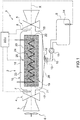
figure 1 schematically shows a device for the production of water on board a vehicle according to the invention; -
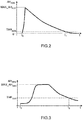
figures 2 and 3 show the development in time of two characteristic indexes of an adsorption step and of a desorption step, respectively, of an adsorbing material used in the device offigure 1 . - In
figure 1 , number 1 indicates, as a whole, a device for the production of water on board a vehicle (not shown) obtained by means of atank 2 containing a quantity (for example, in the form of a solid matrix) of adsorbing material arranged along aduct 3 where an air flow flows. - According to alternative embodiments, the
duct 3 originates from an intake duct, which feeds a fresh air flow to an internal combustion engine of the vehicle or from an independent and dedicated fresh air intake duct. - According to a preferred variant, the flow flowing into the
tank 2 is adjusted by means of an adjustment valve 4, which is arranged along theduct 3 upstream of thetank 2; the adjustment valve 4 is connected to an electronic control unit ECU and is controlled by the electronic control unit ECU itself. - Similarly, according to a preferred variant, the flow flowing out of the
tank 2 is adjusted by means of a respective adjustment valve 5, which is also arranged along theduct 3 downstream of thetank 2; the adjustment valve 5 is also connected to the electronic control unit ECU and is controlled by the electronic control unit ECU itself. - When the vehicle is standing still, the air flow is preferably pushed inside the
tank 2 by means of a forced ventilation system, in particular by means of afan 6, which forces the circulation of the air flow and directs it towards thetank 2. Thefan 6 is arranged along theduct 3 and, according to alternative embodiments, upstream of the adjustment valve 4 or downstream of the adjustment valve 5. - Along the
duct 3 there is also housed adetection device 7 comprising a pair ofsensors 7 designed to determine the absolute humidity of the air flow flowing into thetank 2 through the relative humidity signal detected by afirst sensor 7 and the temperature signal detected by asecond sensor 7. Thedetection device 7 is preferably arranged upstream of thetank 2, in particular it is interposed between thetank 2 and the adjustment valve 4. Thedetection device 7 is connected to the electronic control unit ECU, to which it transmits signals concerning the absolute humidity of the air flow flowing into thetank 2. - Similarly, along the
duct 3 there is housed adetection device 8 comprising a pair ofsensors 8 designed to determine the absolute humidity of the air flow flowing out of thetank 2 through the relative humidity signal detected by afirst sensor 8 and the temperature signal detected by asecond sensor 8. Thedetection device 8 is preferably arranged downstream of thetank 2, in particular it is interposed between thetank 2 and the adjustment valve 5. Thedetection device 8 is connected to the electronic control unit ECU, to which it transmits signals concerning the absolute humidity of the air flow flowing out of thetank 2. - The device 1 also comprises a
tank 9 collecting the water coming from thetank 2, to which it is connected by means of aduct 10, which comes out of the bottom of thetank 2. - According to a preferred variant, along the
duct 10 there is housed a pumping device 11, which draws from thetank 2 in order to feed water to thecollecting tank 9, which is arranged at a greater height than thetank 2. Clearly, in case thecollecting tank 9 is arranged at a smaller height than thetank 2, no pumping device 11 housed along theduct 10 is needed. - Furthermore, the device 1 preferably comprises a
filter 12, which is arranged in the area of the connection between thetank 2 and theduct 10 and is suited to filter the water produced in thetank 2, which flows into thecollecting tank 9. - The water flow flowing out of the
tank 2 and directed towards thetank 9 is adjusted by means of anadjustment valve 13, which is arranged along theduct 10, preferably downstream of thefilter 12 and upstream of the pumping device 11; theadjustment valve 13 is also connected to the electronic control unit ECU and is controlled by the electronic control unit ECU itself. - Finally, there is a
level sensor 14 arranged inside thecollecting tank 9 and suited to detect the level of the water contained inside said collectingtank 9; thelevel sensor 14 is also connected to the electronic control unit ECU, to which it transmits signals concerning the level of the water contained inside thecollecting tank 9. - The
tank 2 is defined by anouter casing 15, which houses at least one matrix M of adsorbing material. According to a preferred variant, theouter casing 15 has a tubular shape. Theouter casing 15 is provided with aside wall 16 and, at its ends, with a front wall and a rear wall indicated with 17 and 18, respectively, infigure 1 . Theside wall 16 preferably has a cylindrical symmetry around a symmetry axis X. - The
outer casing 15 houses, on the inside, aninner container 19, which is provided with aside wall 20 and, at its ends, with a closedfront wall 21 and a closedrear wall 22. Theouter casing 15 preferably has a tubular shape. Theside wall 20 preferably has a cylindrical symmetry around the symmetry axis X. Thewalls inner container 19 are provided with micro-holes so as to permit the passage both of the inflowing air flow and of the water vapour, as described more in detail below. According to a further variant, the micro-holes are made in the entire available area of thewalls inner container 19, so as to maximize the passage of fresh air and water vapour. According to a further variant, the micro-holes are exclusively made in the available area of onesingle wall walls front wall 21 and the rear wall 22). The micro-holes are advantageously distributed in a uniform manner over the entire available area of thewalls container 19. - Between the
inner container 19 and the inner surface of theouter casing 15 there is defined ahollow space 23. According to a preferred variant, the hollow space has a substantially annular shape. Thehollow space 23 preferably is coaxial to the symmetry axis X. Thehollow space 23 is designed to improve the desorption step, as described more in detail hereinafter. - According to a preferred variant, the device 1 is provided with a
heating element 24, which is designed to heat the adsorbing material. - According to a first variant, the
heating element 24 is obtained by means of anelectrical resistance 24 connected to the electronic control unit ECU, which controls it. Theelectrical resistance 24 is preferably buried inside the adsorbing material so as to heat the core of the adsorbing material; alternatively or in addition thereto, theelectrical resistance 24 can be arranged so as to surround the adsorbing material. - According to a further variant, the
heating element 24 is obtained by means of aduct 24 where a fluid circulates, which can alternatively be a portion of the cooling fluid of the internal combustion engine or a portion of the exhaust gases produced by the internal combustion engine or a mix of the cooling fluid of the internal combustion engine and of the exhaust gases produced by the internal combustion engine. The fluid flow introduced into theduct 24 is adjusted by means of a special adjustment valve (not shown); each adjustment valve is connected to the electronic control unit ECU and is controlled by the electronic control unit ECU as a function of the quantity of fluid that is requested/needed for the heating of the adsorbing material. Theduct 24 is preferably buried inside the adsorbing material so as to heat the core of the adsorbing material; alternatively or in addition thereto, theduct 24 can be arranged so as to surround the adsorbing material. - According to a further variant, the
heating element 24 can be obtained by means of a combination of the variants discussed above; in other words, theheating element 24 comprises both theelectrical resistance 24 and theduct 24 where the fluid circulates, which can alternatively be a portion of the cooling fluid of the internal combustion engine or a portion of the exhaust gases produced by the internal combustion engine or a mix of the cooling fluid of the internal combustion engine and of the exhaust gases produced by the internal combustion engine. - According to a preferred variant, the
inner container 19 is also provided with asensor 25 designed to detect the temperature TADM of the adsorbing material. Thetemperature sensor 25 is preferably buried inside the adsorbing material; thetemperature sensor 25 is also connected to the electronic control unit ECU, to which it transmits signals concerning the temperature TADM of the adsorbing material. Thetemperature sensor 25 can alternatively be replaced by a "virtual sensor", i.e. a model for the estimation of the temperature TADM of the adsorbing material stored inside the electronic control unit ECU. - In case the
heating element 24 is obtained by means of theduct 24 where a portion of the exhaust gases produced by the internal combustion engine circulates, the control of the temperature TADM of the adsorbing material is extremely important; the exhaust gases produced by the internal combustion engine have very high temperatures, which could cause the adsorbing material to exceed the temperature above which its chemical-physical properties deteriorate. - The
electrical resistance 24 used asheating element 24 is simpler to be controlled and, in particular, can also be used in case the combustion engine of the vehicle has stopped and the state of charge of a battery of the vehicle is sufficient to ensure the operation thereof. Theelectrical resistance 24 used asheating element 24, however, is affected by the drawback of having a significant impact on the consumptions of the vehicle, especially in case the vehicle is equipped with an energy recovery system, which turns kinetic energy or thermal energy, which would otherwise be lost, into electric energy. - The adsorbing material used in the
tank 2 can be available in the form of matrix or in the form of granules or powders. - The adsorbing material can be chosen, for example, among the following ones: silica gel or clay or calcium sulphate or zeolites or calcium oxide or given metal organic frameworks.
- The choice of the material used in the
tank 2 is made as a function of some parameters, such as the water adsorption speed based on the air temperature and humidity that are typical for the normal operating conditions of the vehicle, the density (and, as a consequence, the size) of the adsorbing material and, finally, the environmental impact and the cost of the adsorbing material. - Experiments have shown that silica gel, which is commonly used to limit humidity inside packages, and some zeolites can be a good compromise of the above-mentioned parameters. Furthermore, metal organic frameworks (MOF) are known, in particular zirconium-based ones, which are characterized bu excellent performances in terms of water adsorption speed, even though they can be relatively expensive.
- Therefore, the electronic control unit ECU is configured to gather a number of parameters, such as the absolute humidity AHIN of the air flow flowing into the
tank 2, which is detected by thedetection device 7; the absolute humidity AHOUT of the air flow flowing out of thetank 2, which is detected by thedetection device 8; the temperature TADM of the adsorbing material detected by thesensor 25; the level of the water contained inside the collectingtank 9, which is detected by thelevel sensor 14. Furthermore, as a function of said gathered parameters, the electronic control unit ECU is configured to control a plurality of elements, among which there are, in particular, theadjustment valves 4, 5, 13, theheating element 24, the fan 6 (if provided) and the pumping device 11 (if provided). - Hereinafter is a description of a method to control a device 1 for the production of water on board a vehicle. The method id divided into an adsorption step and a subsequent desorption step.
- During the adsorption step, the electronic control unit ECU is designed to control both adjustment valves 4 and 5 so that they are open. In this way, the adsorbing material is hit by a continuous air flow and can adsorb a given quantity of water, as a function of the temperature of the air flow. The adsorption speed is not constant and is variable as a function of the humidity of the air flow and of the quantity of water already trapped in the adsorbing material.
- The electronic control unit ECU is configured to continuously monitor, through the signals coming from the
detection devices 
- AHADS adsorption process index;
- AHIN absolute humidity of the air flow flowing into the
tank 2, which is detected by thedetection device 7; and - AHOUT absolute humidity of the air flow flowing out of the
tank 2, which is detected by thedetection device 8. - The adsorption process index AHADS simply is the difference between the absolute AHIN humidity of the air flow flowing into the
tank 2, which is detected by thedetection device 7, and the absolute AHOUT humidity of the air flow flowing out of thetank 2, which is detected by thedetection device 8. - The electronic control unit ECU is further configured to continuously compare the value of the adsorption process index AHADS with a threshold value THRADS, which is determined in a preliminary step and is variable as a function of the temperature of the external air.
- The adsorption step ends (in the instant t1 indicated in
figure 2 ) when, after having reached a peak value MAX_AHADS, the adsorption process index AHADS decreases until it assumes a value which is smaller than or equal to the threshold value THRADS. The electronic control unit ECU is configured to control the closing of both adjustment valves 4 and 5. The threshold value THRADS is the (water) saturation value for the adsorbing material to be reached before going on with the subsequent desorption step. - Assuming that the threshold value THRADS is equal to zero means that the adsorption step necessarily ends only when the adsorbing material is completely saturated with water (even though reaching the condition in which the adsorbing material is completely saturated with water can be inconvenient due to the excess slowing down of the adsorption step). The adsorption process index AHADS, said adsorption process starting in the instant to indicated in
figure 2 , has a development of the type shown infigure 2 ; in particular, the adsorption process index AHADS increases in a substantially increasing manner until it reaches the peak value MAX_AHADS and then decreases in a gradual manner. - The adsorption step described above can evidently take place also when the vehicle is still. When the vehicle is moving, the air flow, which is also moving, allows the adsorption step to be quicker. Therefore, electronic control unit ECU is designed to shift both adjustment valves 4 and 5 to the opening position as soon as it detects that the vehicle has stopped. The electronic control unit ECU is preferably suited to also activate the forced
ventilation system 6 in case the vehicle is still and the state of charge of the battery of the vehicle is sufficient to ensure the operation thereof. - During the subsequent desorption step, after having closed both adjustment valves 4 and 5, the electronic control unit ECU is designed to activate the
heating element 24. - The heating of the adsorbing material carried out through the activation of the
heating element 24 allows the water which was previously trapped in the adsorbing material to be desorbed from the adsorbing material itself, turning into water vapour. The water vapour coming into contact with the walls o thetank 2 condenses and, after the passage to the liquid state, the water is collected on the bottom of thetank 2 in order to be filtered (through the filter 12) and subsequently conveyed to thecollecting tank 9. - According to a preferred variant, in order to support the condensation of the water vapour, the outer surfaces of the tank 2 (in particular, of the outer casing 15) are cooled through the ambient air, forced by the movement of the vehicle, which touches fins (not shown) arranged on the periphery of the
tank 2; or through a low-temperature conditioning circuit (in which a conditioning fluid flows at approximately 50°C), preferably obtained in thewalls tank 2 and, in particular, of theouter casing 15; or through any combination of the variants described above. - Preferably, in order to improve the step during which the water is collected on the bottom of the
tank 2 and conveyed towards thefilter 12, abase wall 26 of thetank 2 has a V-shaped profile inclined towards thefilter 12; the inclined profile of thebase wall 26 allows the water to be conveyed towards the collectingtank 9. - The electronic control unit ECU is configured to continuously monitor, through the signals coming from the
detection devices 
- AHDES desorption process index;
- AHIN absolute humidity of the air flow flowing into the
tank 2, which is detected by thedetection device 7; - AHOUT absolute humidity of the air flow flowing out of the
tank 2, which is detected by thedetection device 8; and - a, b coefficients.
- When the adjustment valves 4, 5 are both closed, inside the
tank 2 the twodetection devices - Hence, the desorption process index AHDES can be represented by the absolute humidity AHIN of the air flow flowing into the
tank 2 detected by the detection device 7 (in case the coefficient a is unitary and the coefficient b is zero) or by the absolute humidity AHOUT of the air flow flowing out of thetank 2 detected by the detection device 8 (in case the coefficient b is unitary and the coefficient a is zero); alternatively, the desorption process index AHDES can be represented by any linear combination (variable as a function of the values assumed by the coefficients a, b and c) of the values of the absolute humidity AHIN of the air flow flowing into thetank 2, which is detected by thedetection device 7, and of the absolute humidity AHOUT of the air flow flowing out of thetank 2, which is detected by thedetection device 8. - The electronic control unit ECU is further configured to continuously compare the value of the desorption process index AHDES with a threshold value THRDES, which is determined in a preliminary step and is variable as a function of the temperature of the external air.
- The desorption step ends (in the instant t3 indicated in
figure 2 ) when, after having reached a peak value MAX_AHDES, the desorption process index AHDES decreases until it assumes a value which is smaller than or equal to the threshold value THRDES. Then, the electronic control unit ECU is configured to deactivate theheating element 24 and, subsequently, control the opening of both adjustment valves 4 and 5. The threshold value THRDES represents the achievement of the complete desorption of the water trapped in the adsorbing material or the achievement of a condition in which the desorption process is excessively slow. - Assuming that the threshold value THRDES is equal to zero means that the desorption step necessarily ends only when the adsorbing material is completely free from water (even though reaching the condition in which the adsorbing material is completely free from water can be inconvenient due to the excess slowing down of the desorption step). The desorption process index AHDES, said desorption process starting in the instant t2 indicated in
figure 3 , typically has a development of the type shown infigure 3 ; in particular, the desorption process index AHDES increases until it reaches the peak value MAX_AHDES, stabilizes for an amount of time with a variable duration and then decreases in a gradual manner. - In case the
level sensor 14 detects that a level of the water contained inside the collectingtank 9 exceeds a limit value, the desorption step cannot evidently start. Before going on with the closing of both adjustment valves 4 and 5 and with the activation of theheating element 24, the electronic control unit ECU is designed to process the signal concerning the level of the water contained inside the collectingtank 9, which is transmitted by thelevel sensor 14, and to compare it with said limit value. - The electronic control unit ECU is further configured to continuously monitor, during the desorption step, the level of the water contained inside the collecting
tank 9 through the signal transmitted by thelevel sensor 14, so as to stop the desorption step as soon as the level of the water contained inside the collectingtank 9 exceeds the threshold value. - According to a further variant, the vehicle is provided with at least one photovoltaic panel designed for the production of a given power suited to ensure the operation of the
electrical resistance 24 used asheating element 24 and/or of the forcedventilation system 6, also in case the combustion engine has stopped (and, for example, the state of charge of the battery of the vehicle is not sufficient). - The adjustment valves, which are indicated with 4 and 5 respectively, are evidently controlled in a synchronous manner (i.e. they are opened or closed at the same time by the electronic control unit ECU). Furthermore, the adjustment valves, which are indicated with 4 and 5 respectively, are evidently controlled in a concordant manner, i.e. jointly or in a corresponding fashion (which means that both adjustment valves 4, 5 are open or closed and it can never happen that an adjustment valve 4, 5 is open while the other adjustment valve 5 is closed).
- The device 1 for the production of water on board a vehicle and the method to control said device 1, as disclosed above, have some advantages. First of all, they are simple and economic to be manufactured and implemented, the device 1 is compact and allows a significant quantity of water to be used on board the vehicle to be produced in an efficient manner.
Claims (25)
- A device (1) for the production of water on board a vehicle comprising:a duct (3), where an air flow flows on the inside;a first tank (2), which contains a quantity of adsorbing material and is arranged along the duct (3) so as to be hit by the air flow;a first adjustment valve (4), which is arranged along the duct (3) upstream of the tank (2); the first adjustment valve (4) is movable between an opening position, in which the air flow can flow towards the first tank (2), and a closing position, in which the air flow cannot flow towards the first tank (2), and vice versa;a second adjustment valve (5), which is also arranged along the duct (3) downstream of the tank (2); the second adjustment valve (5) is movable between an opening position, in which the air flow can flow out of the first tank (2), and a closing position, in which the air flow cannot flow out of the first tank (2), and vice versa;a heating element (24), which is designed to heat the adsorbing material when the first and the second adjustment valves (4, 5) are in the closing position, so as to cause the desorption of the water previously trapped in the adsorbing material;a first detection device (8), which is designed to detect the absolute humidity of the air flow flowing out of the tank (2) and is housed along the duct (3) interposed between the tank (2) and the second adjustment valve (5);a second detection device (7), which is designed to detect the absolute humidity of the air flow flowing into the tank (2) and is housed along the duct (3) interposed between the tank (2) and the first adjustment valve (4); andan electronic control unit (ECU), which is connected to the first detection device (8) and to the second detection device (7) and is designed to control the first and the second adjustment valve (4, 5) in a synchronous and concordant manner as a function of the absolute humidity detected by the detection devices (7, 8).
- A device according to claim 1, wherein the adsorbing material is housed in a container (19) arranged inside the tank (2) provided with walls (20, 21, 22) that are at least partially micro-perforated.
- A device according to claim 2, wherein between the container (19) and the tank (2) there is defined a hollow space (23), which is created in order to improve the desorption of the water trapped in the adsorbing material.
- A device according to any one of the preceding claims and comprising a sensor (25), which is designed to detect the temperature of the adsorbing material and preferably is buried inside the adsorbing material.
- A device according to any one of the preceding claims, wherein the heating element (24) is buried inside the adsorbing material, so as to heat the heart of the adsorbing material.
- A device according to any one of the preceding claims, wherein the heating element (24) is arranged so that it surrounds the adsorbing material, so as to heat the periphery of the adsorbing material.
- A device according to any one of the preceding claims, wherein the heating element (24) is obtained by means of an electrical resistance (24).
- A device according to any one of the preceding claims, wherein the heating element (24) is obtained by means of a channel (24) where a fluid circulates, which can alternatively be a portion of the cooling fluid of an internal combustion engine of the vehicle or a portion of the exhaust gases produced by said internal combustion engine or a mix of the cooling fluid and of the exhaust gases of said internal combustion engine.
- A device according to any one of the preceding claims and comprising a forced ventilation system (6), which is arranged along the duct (3) so as to force the air flow flowing into the tank (2), preferably upstream of the first adjustment valve (4) or downstream of the second adjustment valve (5).
- A device according to any one of the preceding claims and comprising a second tank (9) to collect the water coming from the first tank (2), to which it is connected by means of a pipe (10) coming out of the first tank (2).
- A device according to claim 10 and comprising a pumping device (11), which is arranged along the pipe (10) so as to get water from the first tank (2) and feed it to the second tank (9).
- A device according to claim 10 or 11 and comprising a filter (12), which is arranged in the area of the connection between the first tank (2) and the pipe (10) and is suited to filter the water produced in the first tank (2), which flows into the second tank (9).
- A device according to any one of the claims from 10 to 12 and comprising a third adjustment valve (13), which is arranged along the pipe (10).
- A device according to any one of the claims from 10 to 13 and comprising a level sensor (14), which is arranged inside the second tank (9).
- A device according to any one of the claims from 10 to 14, wherein a base wall (26) of the first tank (2) has a V-shaped profile, which is inclined so as to convey the water towards the second tank (9).
- A device according to any one of the preceding claims, wherein the adsorbing material is chosen among: silica gel or clay or calcium sulphate or zeolites or calcium oxide or metal organic frameworks, in particular zirconium-based ones.
- A device according to any one of the preceding claims, wherein, in order to allow the first tank (2) to cool down, the outer surfaces of the first tank (2) have, connected to them, peripheral fins.
- A device according to any one of the preceding claims, wherein, in order to allow it to cool down, the first tank (2) is provided with a conditioning circuit, in which a conditioning fluid preferably flows at temperatures around 50°C.
- A device according to any one of the preceding claims, wherein the inner surfaces of the first tank (2) are treated by means of a proper surface treatment, in particular in order to increase surface roughness.
- A method to control a device (1) for the production of water on board a vehicle realized according to any one of the claims from 1 to 19 and comprising:an adsorption step, in which the adsorbing material is hit by the air flow and the first and the second adjustment valves (4, 5) are kept open and the heating element (24) is deactivated; wherein the adsorption step comprises the sub-steps of detecting the development of an adsorption process index (AHADS) and comparing it with a first threshold value (THRADS), and wherein the adsorption step is interrupted when the adsorption process index (AHADS) is smaller than or equal to the first threshold value (THRADS); anda desorption step for the desorption of the water trapped in the adsorbing material, in which the first and the second adjustment valves (4, 5) are kept closed and the heating element (24) is activated; wherein the desorption step comprises the sub-steps of detecting the development of a desorption process index (AHDES) and comparing it with a second threshold value (THRDES), and wherein the desorption step is interrupted when the desorption process index (AHDES) is smaller than or equal to the second threshold value (THRDES).
- A method according to claim 20 and comprising the further step of controlling the first and the second adjustment valves (4, 5) in a synchronous and concordant manner.
- A method according to claim 20 or 21, wherein the adsorption process index (AHADS) is calculated through the difference between the absolute humidity (AHIN) of the air flow flowing into the first tank (2) and the absolute humidity (AHOUT) of the air flow flowing out of the first tank (2).
- A method according to any one of the claims from 20 to 22, wherein the desorption process index (AHDES) is represented by the absolute humidity (AHIN) of the air flow flowing into the first tank (2) or by the absolute humidity (AHOUT) of the air flow flowing out of the first tank (2) or by a linear combination of the absolute humidity (AHIN) of the air flow flowing into the first tank (2) and of the absolute humidity (AHOUT) of the air flow flowing out of the first tank (2).
- A method according to any one of the claims from 20 to 23, wherein the first threshold value (THRADS) and/or the second threshold value (THRDES) are variable depending on the temperature of the air on the outside.
- A method according to any one of the claims from 20 to 24, wherein the device (1) is provided with a second tank (9) to collect the water coming from the first tank (2), to which it is connected by means of a pipe (10) coming out of the first tank (2); the method comprises the further step of inhibiting the desorption step in case the water level inside the second tank (9) is greater than or equal to a limit value.
Applications Claiming Priority (1)
| Application Number | Priority Date | Filing Date | Title |
|---|---|---|---|
| IT201800002724A IT201800002724A1 (en) | 2018-02-15 | 2018-02-15 | DEVICE FOR THE PRODUCTION OF WATER ON BOARD A VEHICLE AND METHOD FOR THE CONTROL OF SAID DEVICE |
Publications (1)
| Publication Number | Publication Date |
|---|---|
| EP3527726A1 true EP3527726A1 (en) | 2019-08-21 |
Family
ID=62167674
Family Applications (1)
| Application Number | Title | Priority Date | Filing Date |
|---|---|---|---|
| EP19156987.0A Withdrawn EP3527726A1 (en) | 2018-02-15 | 2019-02-13 | Device for the production of water on board a vehicle and method to control said device |
Country Status (4)
| Country | Link |
|---|---|
| US (1) | US20190247787A1 (en) |
| EP (1) | EP3527726A1 (en) |
| CN (1) | CN110159400A (en) |
| IT (1) | IT201800002724A1 (en) |
Families Citing this family (3)
| Publication number | Priority date | Publication date | Assignee | Title |
|---|---|---|---|---|
| CN111236360B (en) * | 2020-01-20 | 2021-03-26 | 浙江农林大学 | An automatic water intake system that gathers air and water components |
| CN113445571A (en) * | 2020-03-24 | 2021-09-28 | 欧军飞 | Method for improving water vapor collection efficiency of MOF-801 from unsaturated air |
| DE102022128517A1 (en) | 2022-10-27 | 2024-05-02 | Cariad Se | Control unit, in particular for a motor vehicle, motor vehicle, and method for operating a control unit which is cooled by cooling water |
Citations (5)
| Publication number | Priority date | Publication date | Assignee | Title |
|---|---|---|---|---|
| DE3525237A1 (en) * | 1985-07-15 | 1987-01-15 | Kaubek Fritz | DEHUMIDIFIERS ACCORDING TO THE SORPTION PRINCIPLE |
| DE19918591A1 (en) * | 1999-04-23 | 2000-10-26 | Fev Motorentech Gmbh | Engine operation making good use of water from exhaust gases, recovers water with advanced membrane, to be injected in air inlet manifold and to be mixed with solid urea for injection into exhaust ahead of catalyst |
| US20040107832A1 (en) * | 2002-12-06 | 2004-06-10 | Stephen Tongue | Temperature swing humidity collector using powerplant waste heat |
| DE102011101006A1 (en) * | 2011-05-10 | 2012-10-25 | Audi Ag | Method for manufacturing watery urea solution in motor vehicle, involves supplying predetermined quantity of ammonia granulate and predetermined quantity of water belonging to quantity of ammonia granulate to mixing chamber |
| IT201700025325A1 (en) | 2017-03-07 | 2018-09-07 | Magneti Marelli Spa | METHOD AND APPARATUS FOR THE SUPPLY OF WATER TO A TANK OF A DISCHARGE SYSTEM PROVIDED WITH POST TREATMENT OF EXHAUST GAS FOR A COMBUSTION ENGINE |
Family Cites Families (5)
| Publication number | Priority date | Publication date | Assignee | Title |
|---|---|---|---|---|
| IL124978A (en) * | 1998-06-17 | 2003-01-12 | Watertech M A S Ltd | Method and apparatus for extracting water from atmospheric air |
| CN1131359C (en) * | 2001-06-21 | 2003-12-17 | 上海交通大学 | Adsorption air water-intaking equipment |
| JP3926694B2 (en) * | 2001-09-07 | 2007-06-06 | 本田技研工業株式会社 | Exhaust gas purification device state determination device |
| US20120006193A1 (en) * | 2010-07-09 | 2012-01-12 | Subir Roychoudhury | Adsorption-desorption apparatus and process |
| CN103587373B (en) * | 2012-08-16 | 2017-09-19 | 福特环球技术公司 | Vehicle climate control system and the method for vehicle car atmosphere control system |
-
2018
- 2018-02-15 IT IT201800002724A patent/IT201800002724A1/en unknown
-
2019
- 2019-02-13 EP EP19156987.0A patent/EP3527726A1/en not_active Withdrawn
- 2019-02-14 CN CN201910115094.XA patent/CN110159400A/en active Pending
- 2019-02-15 US US16/276,787 patent/US20190247787A1/en not_active Abandoned
Patent Citations (5)
| Publication number | Priority date | Publication date | Assignee | Title |
|---|---|---|---|---|
| DE3525237A1 (en) * | 1985-07-15 | 1987-01-15 | Kaubek Fritz | DEHUMIDIFIERS ACCORDING TO THE SORPTION PRINCIPLE |
| DE19918591A1 (en) * | 1999-04-23 | 2000-10-26 | Fev Motorentech Gmbh | Engine operation making good use of water from exhaust gases, recovers water with advanced membrane, to be injected in air inlet manifold and to be mixed with solid urea for injection into exhaust ahead of catalyst |
| US20040107832A1 (en) * | 2002-12-06 | 2004-06-10 | Stephen Tongue | Temperature swing humidity collector using powerplant waste heat |
| DE102011101006A1 (en) * | 2011-05-10 | 2012-10-25 | Audi Ag | Method for manufacturing watery urea solution in motor vehicle, involves supplying predetermined quantity of ammonia granulate and predetermined quantity of water belonging to quantity of ammonia granulate to mixing chamber |
| IT201700025325A1 (en) | 2017-03-07 | 2018-09-07 | Magneti Marelli Spa | METHOD AND APPARATUS FOR THE SUPPLY OF WATER TO A TANK OF A DISCHARGE SYSTEM PROVIDED WITH POST TREATMENT OF EXHAUST GAS FOR A COMBUSTION ENGINE |
Also Published As
| Publication number | Publication date |
|---|---|
| IT201800002724A1 (en) | 2019-08-15 |
| CN110159400A (en) | 2019-08-23 |
| US20190247787A1 (en) | 2019-08-15 |
Similar Documents
| Publication | Publication Date | Title |
|---|---|---|
| US20190247787A1 (en) | Device for the production of water on board a vehicle and method to control said device | |
| US9422855B2 (en) | Shuttle valve assembly and method for intercooler condensation removal | |
| EP2784430A1 (en) | Vehicular atmosphere purifying apparatus | |
| DE502005003036D1 (en) | METHOD FOR CONTROLLING THE OPERATION OF A HEATABLE SEPARATOR OF A MOTOR VEHICLE | |
| CN104005830A (en) | Strategy for engine cold start emission reduction | |
| KR20010111000A (en) | Vehicle airconditioner and it's control method | |
| EP3708238B1 (en) | Adsorption refrigeration system for the production of demineralized water aboard a motor vehicle, motor vehicle and method for producing demineralized water aboard a motor vehicle | |
| KR102053606B1 (en) | Exhaust gas recirculation cooler | |
| US6792749B2 (en) | Exhaust gas purifying apparatus for internal combustion engine | |
| KR102257483B1 (en) | Humidity Proof System of Electric Control Box | |
| US6945034B2 (en) | Exhaust gas purifying apparatus for internal combustion engine | |
| US6758033B2 (en) | State determining apparatus for exhaust gas purifier | |
| CN101614168A (en) | Be used to have the engine start control of the motor of hydrocarbon retaining system | |
| CN202954873U (en) | Urea box used for diesel engine tail gas post-processing silicon controlled rectifier (SCR) system | |
| US8590294B2 (en) | Engine particulate filter regeneration | |
| JP2022152076A (en) | Co2 separation device of internal combustion engine | |
| EP2957757B1 (en) | Apparatus and method for treating gas to be delivered to a combustion process in an internal combustion engine | |
| CN101614167A (en) | Hydrocarbon retaining system and extract system | |
| CN103061897A (en) | Engine throttle body and heating control method thereof | |
| JP2008291801A (en) | Exhaust device temperature control device | |
| CN101614165B (en) | Hydrocarbon retaining system configuration for an internal combustion engine | |
| CN114607539A (en) | Intake system with hydrocarbon purge valve | |
| JP5579040B2 (en) | Exhaust heat insulation device | |
| CN221256970U (en) | Novel auxiliary air inlet heating system | |
| JPH0913960A (en) | Combine system of catalyst heating device and cooling device |
Legal Events
| Date | Code | Title | Description |
|---|---|---|---|
| PUAI | Public reference made under article 153(3) epc to a published international application that has entered the european phase |
Free format text: ORIGINAL CODE: 0009012 |
|
| AK | Designated contracting states |
Kind code of ref document: A1 Designated state(s): AL AT BE BG CH CY CZ DE DK EE ES FI FR GB GR HR HU IE IS IT LI LT LU LV MC MK MT NL NO PL PT RO RS SE SI SK SM TR |
|
| AX | Request for extension of the european patent |
Extension state: BA ME |
|
| STAA | Information on the status of an ep patent application or granted ep patent |
Free format text: STATUS: THE APPLICATION IS DEEMED TO BE WITHDRAWN |
|
| 18D | Application deemed to be withdrawn |
Effective date: 20200222 |