EP3527676A1 - Method for manufacturing molten iron and apparatus for manufacturing molten iron using same - Google Patents
Method for manufacturing molten iron and apparatus for manufacturing molten iron using same Download PDFInfo
- Publication number
- EP3527676A1 EP3527676A1 EP17862794.9A EP17862794A EP3527676A1 EP 3527676 A1 EP3527676 A1 EP 3527676A1 EP 17862794 A EP17862794 A EP 17862794A EP 3527676 A1 EP3527676 A1 EP 3527676A1
- Authority
- EP
- European Patent Office
- Prior art keywords
- reducing material
- reducing
- melting
- gasifying furnace
- charging
- Prior art date
- Legal status (The legal status is an assumption and is not a legal conclusion. Google has not performed a legal analysis and makes no representation as to the accuracy of the status listed.)
- Withdrawn
Links
- XEEYBQQBJWHFJM-UHFFFAOYSA-N Iron Chemical compound [Fe] XEEYBQQBJWHFJM-UHFFFAOYSA-N 0.000 title claims abstract description 145
- 229910052742 iron Inorganic materials 0.000 title claims abstract description 72
- 238000004519 manufacturing process Methods 0.000 title claims abstract description 39
- 238000000034 method Methods 0.000 title claims description 16
- 239000000463 material Substances 0.000 claims abstract description 555
- 238000002844 melting Methods 0.000 claims abstract description 178
- 230000008018 melting Effects 0.000 claims abstract description 178
- 239000007789 gas Substances 0.000 claims abstract description 30
- 238000002360 preparation method Methods 0.000 claims abstract description 12
- QVGXLLKOCUKJST-UHFFFAOYSA-N atomic oxygen Chemical compound [O] QVGXLLKOCUKJST-UHFFFAOYSA-N 0.000 claims abstract description 8
- 229910052760 oxygen Inorganic materials 0.000 claims abstract description 8
- 239000001301 oxygen Substances 0.000 claims abstract description 8
- 238000000926 separation method Methods 0.000 claims abstract description 7
- 238000007664 blowing Methods 0.000 claims abstract description 5
- 238000003860 storage Methods 0.000 claims description 67
- 239000003575 carbonaceous material Substances 0.000 claims description 27
- 238000007599 discharging Methods 0.000 claims description 13
- 238000002156 mixing Methods 0.000 claims description 6
- 239000000203 mixture Substances 0.000 claims description 5
- 239000003245 coal Substances 0.000 abstract description 33
- 239000012768 molten material Substances 0.000 abstract description 14
- 239000002994 raw material Substances 0.000 abstract description 11
- 239000011148 porous material Substances 0.000 description 10
- 239000002245 particle Substances 0.000 description 8
- 230000002093 peripheral effect Effects 0.000 description 8
- 239000000446 fuel Substances 0.000 description 6
- 239000000571 coke Substances 0.000 description 4
- 230000033001 locomotion Effects 0.000 description 4
- 239000004484 Briquette Substances 0.000 description 3
- UQSXHKLRYXJYBZ-UHFFFAOYSA-N Iron oxide Chemical compound [Fe]=O UQSXHKLRYXJYBZ-UHFFFAOYSA-N 0.000 description 2
- 238000000748 compression moulding Methods 0.000 description 2
- 238000009826 distribution Methods 0.000 description 2
- 239000000155 melt Substances 0.000 description 2
- 238000012986 modification Methods 0.000 description 2
- 230000004048 modification Effects 0.000 description 2
- OKTJSMMVPCPJKN-UHFFFAOYSA-N Carbon Chemical compound [C] OKTJSMMVPCPJKN-UHFFFAOYSA-N 0.000 description 1
- 238000003723 Smelting Methods 0.000 description 1
- 239000000654 additive Substances 0.000 description 1
- 230000000996 additive effect Effects 0.000 description 1
- 230000000712 assembly Effects 0.000 description 1
- 238000000429 assembly Methods 0.000 description 1
- 229910052799 carbon Inorganic materials 0.000 description 1
- 238000003763 carbonization Methods 0.000 description 1
- 238000002485 combustion reaction Methods 0.000 description 1
- 230000000694 effects Effects 0.000 description 1
- 238000009434 installation Methods 0.000 description 1
- 235000000396 iron Nutrition 0.000 description 1
- 238000012856 packing Methods 0.000 description 1
- 239000008188 pellet Substances 0.000 description 1
- 239000000843 powder Substances 0.000 description 1
- 238000011946 reduction process Methods 0.000 description 1
Images



Classifications
-
- C—CHEMISTRY; METALLURGY
- C21—METALLURGY OF IRON
- C21B—MANUFACTURE OF IRON OR STEEL
- C21B13/00—Making spongy iron or liquid steel, by direct processes
- C21B13/0006—Making spongy iron or liquid steel, by direct processes obtaining iron or steel in a molten state
- C21B13/0013—Making spongy iron or liquid steel, by direct processes obtaining iron or steel in a molten state introduction of iron oxide into a bath of molten iron containing a carbon reductant
-
- C—CHEMISTRY; METALLURGY
- C21—METALLURGY OF IRON
- C21B—MANUFACTURE OF IRON OR STEEL
- C21B13/00—Making spongy iron or liquid steel, by direct processes
- C21B13/14—Multi-stage processes processes carried out in different vessels or furnaces
- C21B13/143—Injection of partially reduced ore into a molten bath
-
- C—CHEMISTRY; METALLURGY
- C21—METALLURGY OF IRON
- C21B—MANUFACTURE OF IRON OR STEEL
- C21B13/00—Making spongy iron or liquid steel, by direct processes
- C21B13/0066—Preliminary conditioning of the solid carbonaceous reductant
-
- C—CHEMISTRY; METALLURGY
- C21—METALLURGY OF IRON
- C21B—MANUFACTURE OF IRON OR STEEL
- C21B13/00—Making spongy iron or liquid steel, by direct processes
- C21B13/0073—Selection or treatment of the reducing gases
-
- C—CHEMISTRY; METALLURGY
- C21—METALLURGY OF IRON
- C21B—MANUFACTURE OF IRON OR STEEL
- C21B5/00—Making pig-iron in the blast furnace
- C21B5/008—Composition or distribution of the charge
Definitions
- the present invention discloses a molten iron manufacturing method which improves a fuel charging method and a molten iron manufacturing apparatus using the same.
- the so-called FINEX or COREX process is a direct iron ore smelting and reduction process for solving the problems of the blast furnace process. It directly uses ordinary coal as a fuel and reducing material, and directly uses iron ore as an iron source to the melting and gasifying furnace to produce molten iron.
- the coal used as a fuel is directly charged into the upper side of the melting and gasifying furnace in the form of lump, or coal in the form of powder is made into brequet and charged into the upper side of the melting and gasifying furnace. Powdered coal is blown through the tuyere of a blast furnace.
- coal When the coal is heated above 500°C, volatile components are released through the carbonization process and become a char composed of fixed carbon and ash.
- the furnace temperature in the blast furnace is not as high as 200°C, but the temperature of the dome part is maintained at over 1000°C in the melting and gasifying furnace. Therefore, when undried coal is charged into the melting and gasifying furnace, during the process of releasing volatile components from bed and making a char, coal is divided into small particles.
- coal is pre-dried and charged with coal and raw materials that have not been dry.
- the productivity in the melting and gasifying furnace can be increased because the division is relatively less than that of an undried coal.
- the flow in which the high-temperature reducing gas generated from the combustion zone passes through the bed, heat-exchanges, reduces the raw material, and then flows out to the dome portion, and the flow in which the melted material flows to the bottom of the melting and gasifying furnace and discharges to the iron notch should be stable.
- the molten material cannot flow down to the bottom of the melting and gasifying furnace, so that the molten material fills the pores and the flow of the reducing gas is biased toward the reduced pores. As a result, the gas flow is not stabilized, so that the productivity is deteriorated and the operation cost is increased.
- a molten iron manufacturing method and a molten iron manufacturing apparatus using the same, which can stabilize the flow of the molten material and the reducing gas by improving the coal charging structure into the melting and gasifying furnace are provided.
- a method of manufacturing molten iron by charging a reduced material and a reducing material supplied from a reducing furnace into a melting and gasifying furnace, blowing oxygen to manufacture molten iron, and supplying a reducing gas to a reducing furnace to reduce iron ore may include a reduced material preparation step of preparing a reduced material, a reducing material preparation step of preparing a first reducing material which is pre-dried and a second reducing material which is not pre-dried without being mixed with each other as a reducing material, and a charging step of charging the reduced material and the reducing material into the melting and gasifying furnace, wherein the charging step includes a separation charging step of charging the first reducing material and the second reducing material into the melting and gasifying furnace without being mixed with each other.
- a method of manufacturing molten iron by charging a reduced material and a reducing material supplied from a reducing furnace into a melting and gasifying furnace, blowing oxygen to manufacture molten iron, and supplying a reducing gas to a reducing furnace to reduce iron ore may include: a reduced material preparation step of preparing a reduced material, a reducing material preparation step of preparing a first reducing material having a relatively large size and a second reducing material having a relatively small size as a reducing material, and a charging step of charging the reduced material and the reducing material into the melting and gasifying furnace, wherein the charging step includes a separation charging step of charging the first reducing material and the second reducing material into the melting and gasifying furnace without being mixed with each other.
- the first reducing material may be charged into the center of the melting and gasifying furnace and the second reducing material may be charged into the periphery of the melting and gasifying furnace.
- the charging step may include a step of mixing the reduced material with the second reducing material to mix the reduced material with the second reducing material and charge to the periphery of the melting and gasifying furnace.
- the reducing material preparation step may include a step of alternately discharging the first reducing material and the second reducing material from each of the first reducing material storage bin containing the first reducing material and the second reducing material storage bin containing the second reducing material and transferring, along the reducing material transferring line.
- the charging step may sequentially charge the first reducing material and the second reducing material, which are alternately transferred to the melting and gasifying furnace, through a distributor installed in the melting and gasifying furnace.
- the charging step may include a step of separating the first reducing material and the second reducing material and transferring to the melting and gasifying furnace, and a step of simultaneously charging the first reducing material and the second reducing material through a additional distributor installed in the melting and gasifying furnace.
- an apparatus for manufacturing a molten iron may include: a reducing furnace for reducing iron-containing material to convert to a reduced material; a melting and gasifying furnace manufacturing molten iron by charging a reduced material and a reducing material; a reduced material storage bin containing the reduced material converted in the reducing furnace; a reduced material transfer line for supplying the reduced material discharged from the reduced material storage bin to the melting and gasifying furnace; a reducing material storage bin containing a reducing material; a reducing material transfer line for supplying the reducing material discharged from the reducing material storage bin to the melting and gasifying furnace; and a distributor installed in the melting and gasifying furnace for charging the transferred reduced material and the lump carbon material into the melting and gasifying furnace,
- the reducing material storage bin may include the first reducing material storage bin containing a first reducing material which is pre-dried and the second reducing material storage bin containing a second reducing material which is not pre-dried and the first reducing material and the second reducing material are separately supplied, and wherein the distributor charges the first reducing material and the second reducing material into the melting and gasifying furnace without being mixed with each other.
- an apparatus for manufacturing a molten iron may include: a reducing furnace for reducing iron-containing material to convert to a reduced material; a melting and gasifying furnace manufacturing molten iron by charging a reduced material and a reducing material; a reduced material storage bin containing the reduced material converted in the reducing furnace; a reduced material transfer line for supplying the reduced material discharged from the reduced material storage bin to the melting and gasifying furnace; a reducing material storage bin containing a reducing material; a reducing material transfer line for supplying the reducing material discharged from the reducing material storage bin to the melting and gasifying furnace; and a distributor installed in the melting and gasifying furnace for charging the transferred reduced material and the lump carbon material into the melting and gasifying furnace,
- the reducing material storage bin may include a first reducing material storage bin containing a first reducing material having a relatively large size, and a second reducing material storage bin containing a second reducing material having a relatively small size, and the first reducing material and the second reducing material are separately supplied and wherein the distributor charges the first reducing material and the second reducing material into the melting and gasifying furnace without being mixed with each other.
- the distributor may be configured to charge the first reducing material to the center of the melting and gasifying furnace and the second reducing material to the periphery of the melting and gasifying furnace.
- the reducing material storage bin may alternately discharge the first reducing material and the second reducing material by alternately opening and closing the first reducing material storage bin and the second reducing material storage bin, along the reducing material transfer line.
- the apparatus may further include a charging material transfer pipe connected to the reduced material transfer line and the reducing material transfer line and installed in the melting and gasifying furnace to supply the reduced material and the lump carbon material to the distributor, wherein the reduced material transfer line may be configured to be opened when the second reducing material is transferred to the charging material transfer pipe to supply the reduced material to the charging material transfer pipe and charge into the melting and gasifying furnace with the second reducing material.
- the distributor may be configured to sequentially charge the first reducing material and the second reducing material, which are alternately transferred through the charging material transfer pipe, to the melting and gasifying furnace.
- the reducing material transfer line may further comprise an additional first transfer line transferring the first reducing material to separately transferring the first reducing material and the second reducing material through the first transfer line and the reducing material transfer line
- the apparatus may further comprise an additional first distributor installed in the melting and gasifying furnace and connected to the first transfer line to separate the first reducing material and the second reducing material by the first distributor and the distributor to simultaneously charge into the melting and gasifying furnace
- the apparatus may further include a reducing gas supply line for supplying the reducing gas discharged from the melting and gasifying furnace to the reducing furnace.
- the reducing furnace may be a fluidized bed type reducing furnace or a packed bed type reducing furnace.
- the coal, that is pre-dried may be charged to the center of the melting and gasifying furnace and the coal, that is not pre-dried, may be charged to the periphery of the melting and gasifying furnace to reduce the resistance against the flow of the molten material and the flow of the reducing gas and thus the flow may be smoothly maintained.
- the iron-containing material may be iron itself or all materials including iron.
- the iron-containing material may further include an additive.
- the iron-containing material may include iron ore. Iron may also be pure iron, iron oxide or reduced iron.
- the particle size of the iron-containing material may not be limited.
- the iron-containing material may include pellets, fine iron ore, iron ore assemblies, lump irons, and the like.
- the reducing furnace means a manufacturing device by reducing the iron-containing material.
- the reducing furnace may include a fluidized-bed reducing furnace or packed-bed reducing furnace.
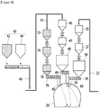
- FIG. 1 schematically shows an apparatus for manufacturing molten iron according to the present embodiment.
- the molten iron manufacturing apparatus shown in Fig. 1 is merely for illustrating the present invention, and the present invention is not limited thereto. Therefore, the apparatus for manufacturing molten iron can be modified into another form.
- the molten iron manufacturing apparatus 100 illustrated in Figure 1 includes a reducing furnace 10; a melting and gasifying furnace 20; a reduced material storage bin 30 for containing a reduced material discharged from the reducing furnace 10 and supplying the reduced material to the melting and gasifying furnace; a reduced material transfer line 32 for transferring the reduced material; a reducing material storage bin 40 for containing the lump carbon material as a reducing material; and a reducing material transfer line 46 for transferring the lump carbon material.
- Other devices may also be included if desired.
- An iron-containing material is charged into the reducing furnace 10 to reduce the iron-containing material.
- the iron-containing material to be charged into the reducing furnace 10 is pre-dried and prepared. If necessary, a powdered raw material can be mixed.
- the iron-containing material is converted into a reduced material in the reducing furnace 10.
- the reducing furnace 10 may be a fluidized-bed reducing furnace or a packed-bed reducing furnace.
- the reducing furnace 10 is supplied with the reducing gas from the melting and gasifying furnace 20 through the reducing gas supply line 22 and reduces and fires the iron-containing material.
- the iron-containing material is converted into the reduced material through the reducing furnace 10.
- the reduced material may be manufactured as HCI (Hot Compacted Iron) by compression molding of a HCI manufacturing apparatus.
- the melting and gasifying furnace 20 may manufacture a molten iron from the reduced material.
- a reduced material is charged into the melting and gasifying furnace 20 together with the reducing material.
- lump carbon materials may be used.
- a lump carbon material is prepared and charged into the melting and gasifying furnace 20.
- lump carbon materials may include lumpy coal or coal briquette.
- Coal briquette is manufactured by compression molding of powdered coal.
- cokes can be charged if necessary.
- the melting and gasifying furnace 20 has a structure in which a large number of tuyeres are installed on the outer wall. And oxygen is blown into the melting and gasifying furnace 20 through the tuyere.
- a charging material transfer pipe 50 connected to the reduced material transfer line 32 and the reducing material transfer line 46 to supply a reduced material and a lump carbon material to the melting and gasifying furnace 20 is installed.
- a distributor 60 connected to the charging material transfer pipe 50 for charging the reduced material and the lump carbon material into the melting and gasifying furnace 20 is installed inside the upper end of the melting and gasifying furnace 20.
- the charging material transfer pipe 50 is vertically extended to the upper end of the dome portion of the melting and gasifying furnace 20 and the reduced material transfer line 32 and the reducing material transfer line 46 are connected along the charging material transfer pipe 50.
- the reduced material transfer line 32 and the reducing material transfer line 46 are respectively provided, on the exit side, with a reduced material discharging screw 39 and a reducing material discharging screw 49. They are connected to the charging material transfer pipe 50, for supplying the reduced material and reducing material in a fixed quantity or shutting off the supply.
- the reduced material discharge screw 39 is rotated, and the reduced material transferred along the reduced material transfer line 32 is supplied to the charging material transfer pipe 50 in a fixed amount.
- the reducing material discharging screw 49 is rotated, the reducing material transferred along the reducing material transfer line 46 is supplied to the charging material transfer pipe 50 in a fixed amount.
- the charging material transfer pipe 50 may mix the reduced material supplied through the reduced material transfer line 32 and the reducing material supplied through the reducing material transfer line 46 to supply the mixture to the distributor 60 connected to the lower end.
- the distributor 60 may be, for example, a device (Gimbal Distributor) for controlling the distribution while charging raw materials and coal briquette in a molten iron manufacturing facility called FINEX.
- the distributor 60 may include a rotation chute for switching the direction of introduction of the raw material at the lower end and a driving unit for rotating the rotation chute and varying the tilting angle so as to vary the tilting angle of the rotation chute along the circumferential direction.
- the charging material is introduced into a desired region in the melting and gasifying furnace 20 by controlling the dropping position of the charging material.
- the reduced material and the lump carbon material of the reducing material are supplied to the charging material transfer pipe 50 through the reduced material transfer line 32 and the reducing material transfer line 46 and are distributed and charged through the distributor 60 connected to the charging material transfer pipe 50, into the melting and gasifying furnace 20 to form a packed bed.
- the lump carbon material of a reducing material may be divided into a lump carbon material that has been pre-dried and a lump carbon material that has not been pre-dried according to whether it has been pre-dried, and charged into the melting and gasifying furnace 20 without being mixed with each other.
- the reducing material storage bin 40 may include a first reducing material storage bin 42 for containing the first reducing material which is pre-dried and a second reducing material storage bin 44 for containing the second reducing material which is not pre-dried.
- the distributor 60 is configured to charge the first reducing material and the second reducing material to the melting and gasifying furnace 20 without being mixed with each other.
- the first reducing material and the second reducing material are separated from each other in the melting and gasifying furnace 20 without being mixed with each other and charged in the respective regions.
- the pre-dried reducing material and the un-dried reducing material, in the melting and gasifying furnace were mixed and charged into the melting and gasifying furnace 20.
- the pores between the particles having a large size, which are not divided were filled with the particles having a small size, which are divided, so that the size of the pores where reducing gas and the melt can flow was reduced and the porosity was reduced. Therefore, the flow of the gas or the molten material was not smooth.
- the first reducing material and the second reducing material can be determined by whether coal is dried or not. As already known, the division of pre-dried coal is less than that of un-dried coal in the melting and gasifying furnace.
- the lump coal material can be sorted by size and differentiated as the first reducing material and the second reducing material.
- a relatively large-sized lump carbon material may mean the upper 20% level of the particle size, when the prepared lump carbon material is sorted by particle size.
- the division can be made less than the relatively small-sized lump carbon material in the melting and gasifying furnace.
- the first reducing material can be understood as a lump carbon material having a relatively larger size than the second reducing material or a pre-dried carbon material having less division in the melting and gasifying furnace.
- the second reducing material can be understood as a lump carbon material having a relatively small size than the first reducing material or an un-pre-dried carbon material having more division in the melting and gasifying furnace.
- the first reducing material is charged to the center of the melting and gasifying furnace 20 and the second reducing material is charged to the periphery of the melting and gasifying furnace 20.
- the central portion of the melting and gasifying furnace 20 refers to an inner central region, and the peripheral portion refers to an inner wall region of the melting and gasifying furnace 20.
- FIG. 2 shows a structure for charging a charging material into the melting and gasifying furnace 20 according to the present embodiment.
- the first reducing material storage bin 42 and the second reduction material storage bin 44 may be configured to be alternately opened and closed in sequence along the reducing material transfer line 46 to alternately discharge the first reducing material and the second reducing material. That is, upon discharging the first reducing material, the second reducing material storage bin 44 may be closed to prevent discharging the second reducing material. Upon discharging the second reducing material, the first reducing material storage bin 42 may be closed to prevent discharging the first reducing material.
- the respective storage bins are alternately opened in sequence so that the first reducing material and the second reducing material can be alternately transferred to the charging material transfer pipe 50 connected to the reducing material transfer line 46 in a separated state without being mixed with each other.
- the distributor 60 is configure to sequentially charge the first reducing material and the second reducing material.
- the first reducing material may be charged to the center portion of the melting and gasifying furnace 20 and the second reducing material may be charged to the periphery portion of the melting and gasifying furnace 20.
- the distributor 60 may finally control the falling position of the charging material discharged through the rotation chute.
- the distributor 60 may vary the tilting angle of the rotation chute in accordance with the supply timing of the first reducing material and the second reducing material alternately supplied along the charging material transfer pipe 50.
- the first reducing material and the second reducing material can be separately charged at desired positions.
- the distributor 60 directs the rotation chute toward the center of the melting and gasifying furnace 20.
- the rotation chute is directed to the periphery of the melting and gasifying furnace 20.
- the control operation of the distributor 60 may calculate, in accordance with the opening and closing timings of the first reducing material storage bin 42 and the second reducing material storage bin 44 and the moving speed of the reducing material transfer line 46, the timing at which the first reducing material and the second reducing material are supplied to the reducing material transfer pipe 50. Further, the rotation chute of the distributor 60 may be controlled in accordance with the supply timing of the respective reducing materials. Thereby, the first reducing material and the second reducing material may be charged into a desired region in the melting and gasifying furnace 20.
- the reduced material charged into the melting and gasifying furnace 20 may be configured to be charged into the periphery of the melting and gasifying furnace 20 along with the second reducing material.
- the reduced material transfer line 32 may be opened when the second reducing material is transferred to the charging material transfer pipe 50 to supply the reduced material to the charging material transfer pipe 50.
- the reduced material discharge screw 39 installed in the reduced material transfer line 32 may be operated to supply the reduced material to the charging material transfer pipe 50 and, together with the second reducing material supplied to the charging material transfer pipe 50, may be charged into the periphery of the gasifying furnace 20.
- the reducing material discharging screw 39 installed in the reduced material transfer line 32 stops the operation to prevent the reduced material from being supplied to the first reducing material.
- the reduced material may be supplied only when the second reducing material is supplied and mixed with the second reducing material, and the mixture is charged into the periphery of the melting and gasifying furnace 20.
- a plurality of storage bins 45, middle bins 47, and charging bins 48 may be further provided along the reducing material transfer line 46 for smooth and quantitative supply of the reducing material and may be sequentially connected.
- the first reducing material and the second reducing material which are alternately supplied along the reducing material transfer line 46 are loaded and transferred, in the same order, while passing through the storage bins, the middle bins, and the charging bins.
- the first reducing material and the second reducing material may be separately supplied to the reducing material transfer pipe 50.
- the first reducing material and the second reducing material may be differentiated and separated through the distributor 60.
- a plurality of storage bins 35, intermediate bins 37, and charging bins 38 may be further provided along the reduced material transfer line 32 for more smoothly and quantitatively supplying the reduced material, and may be sequentially connected.
- the reduced material went through the reducing furnace 10 is contained in the reduced material storage bin 30 and is prepared and supplied to the charging material transfer pipe 50 through the reduced material transfer line 32.
- the reducing material is differentiated by a first reducing material and a second reducing material, which are separately stored in a first reducing material storage bin 42 and a second reducing material storage bin 44, respectively.
- the first reducing material storage bin 42 and the second reducing material storage bin 44 are alternately opened in order to sequentially supply the first reducing material and the second reducing material along the reducing material transfer line 46.
- the first reducing material and the second reducing material supplied along the reducing material transfer line 46 are alternately supplied to the charging material transfer pipe 50 connected to the exit side of the reducing material transfer line 46.
- the distributor 60 installed in the melting and gasifying furnace 20 separates the first reducing material and the second reducing material supplied through the charging material transfer pipe 50 and alternately charges them in the melting and gasifying furnace 20.
- the distributor 60 is controlled and driven in accordance with the supply timing of the first reducing material and the second reducing material. It sequentially charges the first reducing material to the center of the melting and gasifying furnace 20 and the second reducing material to the periphery of the melting and gasifying furnace 20.
- the reduced material is supplied to the charging material transfer pipe 50 through the reduced material transfer line 32 in accordance with the timing when the second reducing material is charged into the melting and gasifying furnace 20 in order.
- the reduced material is mixed with the second reducing material and charged into the melting and gasifying furnace 20.
- the first reducing material and the second reducing material are separated from each other, and the first reducing material is distributed in the center of the melting and gasifying furnace 20 and the second reducing material is distributed in the peripheral portion.
- FIG. 3 schematically shows the charging state of the charging material charged in the melting and gasifying furnace according to the present embodiment.
- the first reducing material is charged into the center of the melting and gasifying furnace 20, and the second reducing material mixed with the reduced material is charged into the periphery of the melting and gasifying furnace 20.
- the distributor sequentially charges the first reducing material and the second reducing material.
- the first reducing material charged in the center of the melting and gasifying furnace replace the lower bed as time passes by and fills the hearth area under the tuyere of the melting and gasifying furnace.
- the molten material can be more easily flowed down to the bottom of the melting and gasifying furnace.
- the gas can flow more easily to the central portion of the melting and gasifying furnace. Further, the charging material at the center of the melting and gasifying furnace is heated to increase the temperature. Then, due to the lower viscosity, the molten material may flow down more easily.
- the second reducing material is charged in the peripheral portion of the melting and gasifying furnace.
- the size of the pores is not increased but the porosity is larger than that of the conventional mixed packing structure. That is, in the melting and gasifying furnace, the resistance of the entire bed with respect to the flowing down of molten material and the resistance of the entire bed with respect to the flowing up of the reducing gas are reduced. Due to the reduced resistance, the gas flow is stabilized, and the discharge of the molten material is smooth. Thus, the operation of the melting and gasifying furnace can be stabilized and the productivity can be increased.
- the reduced material as a raw material is charged to the peripheral portion of the melting and gasifying furnace together with the second reducing material.
- oxygen may be blown through the tuyere on the outer wall.
- the gas flows up mainly to the peripheral portion of the melting and gasifying furnace, so that the reducing gas may easily reduce and heat the raw material.
- the first reducing material and the second reducing material are separated from each other and charged in the melting and gasifying furnace.
- the gas flow may be stabilized and the flow of the molten material is smooth so that the productivity can be increased and the fuel consumption can be reduced.
- the production cost can be lowered by minimizing the amount of pre-dried coal that is expensive to produce.
- FIG. 4 and FIG. 5 illustrate the charging structure of charging material according to another embodiment.
- the reducing material transfer line 46 is further provided with an additional first transfer line 70 transferring the first reducing material to separately transferring the first reducing material and the second reducing material through the first transfer line 70 and the reducing material transfer line 46.
- an additional first distributor 80 connected to the first transfer line 70 may be further provided in addition to the distributor 60 connected to the reducing material transfer line 46 to separate the first reducing material and the second reducing material by the first distributor 80 and the distributor 60 and simultaneously charge into the melting and gasifying furnace 20.
- the first distributor 80 supplies only the first reducing material to the center of the melting and gasifying furnace 20 unlike the distributor 60, the first reducing material discharge angle may be fixed to the center of the melting and gasifying furnace.
- the first distributor 80 may have the same structure as that of the distributor 60 and may be configured in which the angle of the rotation chute is set to center. It is sufficient that the first distributor 80 can charge the first reducing material to the center of the melting and gasifying furnace, and its structure and installation position can be variously modified.
- the first transfer line 70 may be connected to the melting and gasifying furnace 20 by branching from one side of the reducing material transfer line 46.
- the first reducing material and the second reducing material may be sequentially supplied to the reducing material transfer line 46 upon opening the first reducing material storage bin 42 and the second reducing material storage bin 44.
- the first reducing material is transferred through the first transfer line 70, and only the second reducing material can be transferred through the reducing material transfer line 46.
- the first reducing material storage bin 42 containing the first reducing material and the second reducing material storage bin 44 containing the second reducing material may be connected to the first transfer line 70 and the reducing material transfer line 46, respectively.
- the reducing material can be separately supplied.
- the first transfer line 70 also may be further provided with a plurality of storage bins 72, intermediate bins 74, and charging bins 76, along the first transfer line 70, for a smoother and a fixed amount supply of the first reducing material, which may be sequentially connected.
- a discharge screw 78 for discharging the first reducing material in a fixed amount may further be provided on the exit side of the first transfer line.
- the reducing material transfer line 46 is connected to the charging material transfer pipe 50 and the charging material transfer pipe 50 is connected to the distributor 60.
- a reduced material transfer line 32 for supplying a reduced material is connected to the charging material transfer pipe 50.
- a first distributor 80 may be installed on the upper portion of the melting and gasifying furnace 20 in addition to the distributor 60.
- the first transfer line 70 may be connected to the first distributor 80 to supply the first reducing material to the first distributor 80.
- the distributor 60 may charge only the second reducing material and the reduced material to the melting and gasifying furnace 20, and the first distributor 80 may charge only the first reducing material transferred along the first transfer line 70 to the melting and gasifying furnace 20.
- the tilting angle of the rotation chute can be set to the periphery of the melting and gasifying furnace 20 so that the second reducing material can be charged into the periphery of the melting and gasifying furnace 20. Since the first distributor 80 also charges only the first reducing material, the tilting angle of the rotation chute can be set to the center of the melting and gasifying furnace 20 so that the first reducing material can be charged to the center of the melting and gasifying furnace 20.
- the charging of the first reducing material and the second reducing material is performed at the same time and continuously.
- the first reducing material and the second reducing material are continuously charged into the melting and gasifying furnace 20, and the first reducing material is distributed to the central portion of the melting and gasifying furnace 20, and the second reducing material is distributed to the peripheral portion.
- Fig. 5 schematically shows the charging state of the charging material charged into the melting and gasifying furnace according to the present embodiment.
- the first reducing material is charged into the center of the melting and gasifying furnace 20, and the second reducing material mixed with the reduced material is charged into the periphery of the melting and gasifying furnace 20.
- the mixing of the first reducing material and the second reducing material can be minimized at the boundary between the center and the periphery of the melting and gasifying furnace.
- the fluctuation of the temperature and the gas composition in the dome portion of the melting and gasifying furnace can be minimized, and the amount of the first reducing material charged into the center portion can be further reduced.
Landscapes
- Engineering & Computer Science (AREA)
- Chemical & Material Sciences (AREA)
- Manufacturing & Machinery (AREA)
- Materials Engineering (AREA)
- Metallurgy (AREA)
- Organic Chemistry (AREA)
- Manufacture Of Iron (AREA)
- Furnace Charging Or Discharging (AREA)
Abstract
Description
- The present invention discloses a molten iron manufacturing method which improves a fuel charging method and a molten iron manufacturing apparatus using the same.
- Generally, about 60% of the world's iron production is produced through the blast furnace process developed from the 14th century. In the blast furnace process, iron ore and cokes are charged onto layers from the upper side of the blast furnace, and hot air and powdered coal are blown through the tuyere to produce molten iron. Cokes and powdered coal are used as a fuel or a reducing material, and cokes which is coal-dried is charged through the upper side of the blast furnace in the form of a lump, and the powdered coal which is not dried is supplied through the tuyere.
- The so-called FINEX or COREX process is a direct iron ore smelting and reduction process for solving the problems of the blast furnace process. It directly uses ordinary coal as a fuel and reducing material, and directly uses iron ore as an iron source to the melting and gasifying furnace to produce molten iron. The coal used as a fuel is directly charged into the upper side of the melting and gasifying furnace in the form of lump, or coal in the form of powder is made into brequet and charged into the upper side of the melting and gasifying furnace. Powdered coal is blown through the tuyere of a blast furnace.
- When the coal is heated above 500°C, volatile components are released through the carbonization process and become a char composed of fixed carbon and ash. The furnace temperature in the blast furnace is not as high as 200°C, but the temperature of the dome part is maintained at over 1000°C in the melting and gasifying furnace. Therefore, when undried coal is charged into the melting and gasifying furnace, during the process of releasing volatile components from bed and making a char, coal is divided into small particles.
- If a small sized char is produced, the gas flow and melt flow in the melting and gasifying furnace deteriorate. Thus, the productivity and efficiency of the melting and gasifying furnace are lowered.
- Conventionally, in order to increase the productivity and efficiency of the melting and gasifying furnace, coal is pre-dried and charged with coal and raw materials that have not been dry. In case of dry coal, the productivity in the melting and gasifying furnace can be increased because the division is relatively less than that of an undried coal.
- In order to stabilize the operation of the melting furnace, the flow in which the high-temperature reducing gas generated from the combustion zone passes through the bed, heat-exchanges, reduces the raw material, and then flows out to the dome portion, and the flow in which the melted material flows to the bottom of the melting and gasifying furnace and discharges to the iron notch should be stable.
- However, for the conventional structure above, since the dried coal is mixed with the un-dried coal and the pores between the dried coal particles having a large size, which are not divided, are filled with un-dried coal particles having a small size, which are divided, there was a problem in that the size of the pores through which the gas and the melt can flow is reduced and the ratio of the pores is reduced to increase the resistance of the melting furnace bed and thus the flow of the reducing gas and the molten material is not smooth.
- Therefore, the molten material cannot flow down to the bottom of the melting and gasifying furnace, so that the molten material fills the pores and the flow of the reducing gas is biased toward the reduced pores. As a result, the gas flow is not stabilized, so that the productivity is deteriorated and the operation cost is increased.
- A molten iron manufacturing method and a molten iron manufacturing apparatus using the same, which can stabilize the flow of the molten material and the reducing gas by improving the coal charging structure into the melting and gasifying furnace are provided.
- In the embodiment, a method of manufacturing molten iron by charging a reduced material and a reducing material supplied from a reducing furnace into a melting and gasifying furnace, blowing oxygen to manufacture molten iron, and supplying a reducing gas to a reducing furnace to reduce iron ore, may include a reduced material preparation step of preparing a reduced material, a reducing material preparation step of preparing a first reducing material which is pre-dried and a second reducing material which is not pre-dried without being mixed with each other as a reducing material, and a charging step of charging the reduced material and the reducing material into the melting and gasifying furnace, wherein the charging step includes a separation charging step of charging the first reducing material and the second reducing material into the melting and gasifying furnace without being mixed with each other.
- In the embodiment, a method of manufacturing molten iron by charging a reduced material and a reducing material supplied from a reducing furnace into a melting and gasifying furnace, blowing oxygen to manufacture molten iron, and supplying a reducing gas to a reducing furnace to reduce iron ore, may include: a reduced material preparation step of preparing a reduced material, a reducing material preparation step of preparing a first reducing material having a relatively large size and a second reducing material having a relatively small size as a reducing material, and a charging step of charging the reduced material and the reducing material into the melting and gasifying furnace, wherein the charging step includes a separation charging step of charging the first reducing material and the second reducing material into the melting and gasifying furnace without being mixed with each other.
- In the separation charging step, the first reducing material may be charged into the center of the melting and gasifying furnace and the second reducing material may be charged into the periphery of the melting and gasifying furnace.
- The charging step may include a step of mixing the reduced material with the second reducing material to mix the reduced material with the second reducing material and charge to the periphery of the melting and gasifying furnace.
- The reducing material preparation step may include a step of alternately discharging the first reducing material and the second reducing material from each of the first reducing material storage bin containing the first reducing material and the second reducing material storage bin containing the second reducing material and transferring, along the reducing material transferring line.
- The charging step may sequentially charge the first reducing material and the second reducing material, which are alternately transferred to the melting and gasifying furnace, through a distributor installed in the melting and gasifying furnace.
- The charging step may include a step of separating the first reducing material and the second reducing material and transferring to the melting and gasifying furnace, and a step of simultaneously charging the first reducing material and the second reducing material through a additional distributor installed in the melting and gasifying furnace.
- In the embodiment, an apparatus for manufacturing a molten iron may include: a reducing furnace for reducing iron-containing material to convert to a reduced material; a melting and gasifying furnace manufacturing molten iron by charging a reduced material and a reducing material; a reduced material storage bin containing the reduced material converted in the reducing furnace; a reduced material transfer line for supplying the reduced material discharged from the reduced material storage bin to the melting and gasifying furnace; a reducing material storage bin containing a reducing material; a reducing material transfer line for supplying the reducing material discharged from the reducing material storage bin to the melting and gasifying furnace; and a distributor installed in the melting and gasifying furnace for charging the transferred reduced material and the lump carbon material into the melting and gasifying furnace,
- The reducing material storage bin may include the first reducing material storage bin containing a first reducing material which is pre-dried and the second reducing material storage bin containing a second reducing material which is not pre-dried and the first reducing material and the second reducing material are separately supplied, and wherein the distributor charges the first reducing material and the second reducing material into the melting and gasifying furnace without being mixed with each other.
- In the embodiment, an apparatus for manufacturing a molten iron may include: a reducing furnace for reducing iron-containing material to convert to a reduced material; a melting and gasifying furnace manufacturing molten iron by charging a reduced material and a reducing material; a reduced material storage bin containing the reduced material converted in the reducing furnace; a reduced material transfer line for supplying the reduced material discharged from the reduced material storage bin to the melting and gasifying furnace; a reducing material storage bin containing a reducing material; a reducing material transfer line for supplying the reducing material discharged from the reducing material storage bin to the melting and gasifying furnace; and a distributor installed in the melting and gasifying furnace for charging the transferred reduced material and the lump carbon material into the melting and gasifying furnace,
- The reducing material storage bin may include a first reducing material storage bin containing a first reducing material having a relatively large size, and a second reducing material storage bin containing a second reducing material having a relatively small size, and the first reducing material and the second reducing material are separately supplied and wherein the distributor charges the first reducing material and the second reducing material into the melting and gasifying furnace without being mixed with each other.
- The distributor may be configured to charge the first reducing material to the center of the melting and gasifying furnace and the second reducing material to the periphery of the melting and gasifying furnace.
- The reducing material storage bin may alternately discharge the first reducing material and the second reducing material by alternately opening and closing the first reducing material storage bin and the second reducing material storage bin, along the reducing material transfer line.
- The apparatus may further include a charging material transfer pipe connected to the reduced material transfer line and the reducing material transfer line and installed in the melting and gasifying furnace to supply the reduced material and the lump carbon material to the distributor,
wherein the reduced material transfer line may be configured to be opened when the second reducing material is transferred to the charging material transfer pipe to supply the reduced material to the charging material transfer pipe and charge into the melting and gasifying furnace with the second reducing material. - The distributor may be configured to sequentially charge the first reducing material and the second reducing material, which are alternately transferred through the charging material transfer pipe, to the melting and gasifying furnace.
- The reducing material transfer line may further comprise an additional first transfer line transferring the first reducing material to separately transferring the first reducing material and the second reducing material through the first transfer line and the reducing material transfer line, and the apparatus may further comprise an additional first distributor installed in the melting and gasifying furnace and connected to the first transfer line to separate the first reducing material and the second reducing material by the first distributor and the distributor to simultaneously charge into the melting and gasifying furnace
- The apparatus may further include a reducing gas supply line for supplying the reducing gas discharged from the melting and gasifying furnace to the reducing furnace.
- The reducing furnace may be a fluidized bed type reducing furnace or a packed bed type reducing furnace.
- As described in the above, according to the present invention, the coal, that is pre-dried, may be charged to the center of the melting and gasifying furnace and the coal, that is not pre-dried, may be charged to the periphery of the melting and gasifying furnace to reduce the resistance against the flow of the molten material and the flow of the reducing gas and thus the flow may be smoothly maintained.
- Accordingly, it is possible to increase the productivity by increasing the heat exchange efficiency while reducing the amount of fuel used in the melting and gasifying furnace.
-
-
FIG. 1 is a schematic view of showing an apparatus for manufacturing molten iron according to an embodiment of the present invention. -
FIG. 2 is a schematic view of showing a structure for charging a charging material into a melting and gasifying furnace of a molten iron manufacturing apparatus according to an embodiment of the present invention. -
FIG. 3 is a schematic cross-sectional view of showing a charge state of a charging material charged into the melting and gasifying furnace according toFIG. 2 . -
FIG. 4 is a schematic view of showing a structure for charging a charging material into a melting and gasifying furnace of a molten iron manufacturing apparatus according to another embodiment of the present invention. -
FIG. 5 is a schematic cross-sectional view of showing a charge state of a charging material charged into the melting and gasifying furnace according toFIG 4 . - The terminology used herein is for the purpose of describing particular embodiments only and is not intended to limit the invention. The singular forms as used herein include plural forms unless the phrases specifically state the opposite meaning thereof. The "comprises" means that a particular characteristic, region, integer, step, motion, element and/or component is specified and that does not exclude the presence or addition of other characteristics, regions, integers, steps, motions, elements, and/or components.
- Hereinafter, embodiments of the present invention will be described with reference to the accompanying drawings so that those skilled in the art can easily carry out the present invention. It will be apparent to those skilled in the art that various modifications and variations can be made in the present invention without departing from the spirit or scope of the invention. Accordingly, the present invention may be embodied in many different forms and should not be construed as limited to the embodiments set forth herein.
- The terminology used herein is for the purpose of describing particular embodiments only and is not intended to limit the invention. The singular forms as used herein include plural forms as long as the phrases do not specifically state the opposite meaning thereof. The "comprises" means that a particular characteristic, region, integer, step, motion, element and/or component is specified and that does not exclude the presence or addition of other characteristics, regions, integers, steps, motions, elements, and/or components.
- In the following description, the iron-containing material may be iron itself or all materials including iron. For example, the iron-containing material may further include an additive. The iron-containing material may include iron ore. Iron may also be pure iron, iron oxide or reduced iron. The particle size of the iron-containing material may not be limited. Thus, the iron-containing material may include pellets, fine iron ore, iron ore assemblies, lump irons, and the like.
- The reducing furnace means a manufacturing device by reducing the iron-containing material. The reducing furnace may include a fluidized-bed reducing furnace or packed-bed reducing furnace.
-
FIG. 1 schematically shows an apparatus for manufacturing molten iron according to the present embodiment. The molten iron manufacturing apparatus shown inFig. 1 is merely for illustrating the present invention, and the present invention is not limited thereto. Therefore, the apparatus for manufacturing molten iron can be modified into another form. - The molten
iron manufacturing apparatus 100 illustrated inFigure 1 includes a reducingfurnace 10; a melting and gasifyingfurnace 20; a reducedmaterial storage bin 30 for containing a reduced material discharged from the reducingfurnace 10 and supplying the reduced material to the melting and gasifying furnace; a reducedmaterial transfer line 32 for transferring the reduced material; a reducingmaterial storage bin 40 for containing the lump carbon material as a reducing material; and a reducingmaterial transfer line 46 for transferring the lump carbon material. Other devices may also be included if desired. - An iron-containing material is charged into the reducing
furnace 10 to reduce the iron-containing material. The iron-containing material to be charged into the reducingfurnace 10 is pre-dried and prepared. If necessary, a powdered raw material can be mixed. The iron-containing material is converted into a reduced material in the reducingfurnace 10. The reducingfurnace 10 may be a fluidized-bed reducing furnace or a packed-bed reducing furnace. The reducingfurnace 10 is supplied with the reducing gas from the melting and gasifyingfurnace 20 through the reducinggas supply line 22 and reduces and fires the iron-containing material. The iron-containing material is converted into the reduced material through the reducingfurnace 10. The reduced material may be manufactured as HCI (Hot Compacted Iron) by compression molding of a HCI manufacturing apparatus. - The melting and gasifying
furnace 20 may manufacture a molten iron from the reduced material. For this, a reduced material is charged into the melting and gasifyingfurnace 20 together with the reducing material. As a reducing material, lump carbon materials may be used. In order to form a coal packed bed in the melting and gasifyingfurnace 20, a lump carbon material is prepared and charged into the melting and gasifyingfurnace 20. Examples of lump carbon materials may include lumpy coal or coal briquette. Coal briquette is manufactured by compression molding of powdered coal. In addition, cokes can be charged if necessary. The melting and gasifyingfurnace 20 has a structure in which a large number of tuyeres are installed on the outer wall. And oxygen is blown into the melting and gasifyingfurnace 20 through the tuyere. - At upper end of the dome portion of the melting and gasifying
furnace 20, a chargingmaterial transfer pipe 50 connected to the reducedmaterial transfer line 32 and the reducingmaterial transfer line 46 to supply a reduced material and a lump carbon material to the melting and gasifyingfurnace 20 is installed. In addition, adistributor 60 connected to the chargingmaterial transfer pipe 50 for charging the reduced material and the lump carbon material into the melting and gasifyingfurnace 20 is installed inside the upper end of the melting and gasifyingfurnace 20. - As illustrated in
Figure 2 , the chargingmaterial transfer pipe 50 is vertically extended to the upper end of the dome portion of the melting and gasifyingfurnace 20 and the reducedmaterial transfer line 32 and the reducingmaterial transfer line 46 are connected along the chargingmaterial transfer pipe 50. The reducedmaterial transfer line 32 and the reducingmaterial transfer line 46 are respectively provided, on the exit side, with a reducedmaterial discharging screw 39 and a reducingmaterial discharging screw 49. They are connected to the chargingmaterial transfer pipe 50, for supplying the reduced material and reducing material in a fixed quantity or shutting off the supply. - If necessary, the reduced
material discharge screw 39 is rotated, and the reduced material transferred along the reducedmaterial transfer line 32 is supplied to the chargingmaterial transfer pipe 50 in a fixed amount. And when the reducingmaterial discharging screw 49 is rotated, the reducing material transferred along the reducingmaterial transfer line 46 is supplied to the chargingmaterial transfer pipe 50 in a fixed amount. The chargingmaterial transfer pipe 50 may mix the reduced material supplied through the reducedmaterial transfer line 32 and the reducing material supplied through the reducingmaterial transfer line 46 to supply the mixture to thedistributor 60 connected to the lower end. - The
distributor 60 may be, for example, a device (Gimbal Distributor) for controlling the distribution while charging raw materials and coal briquette in a molten iron manufacturing facility called FINEX. Thedistributor 60 may include a rotation chute for switching the direction of introduction of the raw material at the lower end and a driving unit for rotating the rotation chute and varying the tilting angle so as to vary the tilting angle of the rotation chute along the circumferential direction. Thus, the charging material is introduced into a desired region in the melting and gasifyingfurnace 20 by controlling the dropping position of the charging material. - The reduced material and the lump carbon material of the reducing material are supplied to the charging
material transfer pipe 50 through the reducedmaterial transfer line 32 and the reducingmaterial transfer line 46 and are distributed and charged through thedistributor 60 connected to the chargingmaterial transfer pipe 50, into the melting and gasifyingfurnace 20 to form a packed bed. - In the present embodiment, the lump carbon material of a reducing material may be divided into a lump carbon material that has been pre-dried and a lump carbon material that has not been pre-dried according to whether it has been pre-dried, and charged into the melting and gasifying
furnace 20 without being mixed with each other. - To this end, in the molten
iron manufacturing apparatus 100 of the present embodiment, the reducingmaterial storage bin 40 may include a first reducingmaterial storage bin 42 for containing the first reducing material which is pre-dried and a second reducingmaterial storage bin 44 for containing the second reducing material which is not pre-dried. Thus, the first reducing material and the second reducing material are separately supplied. Thedistributor 60 is configured to charge the first reducing material and the second reducing material to the melting and gasifyingfurnace 20 without being mixed with each other. - The first reducing material and the second reducing material are separated from each other in the melting and gasifying
furnace 20 without being mixed with each other and charged in the respective regions. The problem that the pores of the dried first reducing material having a large size, which are not divided, are filled with the un-dried second reducing material having a small size, which are divided, is minimized, so that the flow of the gas and the molten material can be smoothly maintained. - In the conventional case, the pre-dried reducing material and the un-dried reducing material, in the melting and gasifying furnace, were mixed and charged into the melting and gasifying
furnace 20. Thus, the pores between the particles having a large size, which are not divided, were filled with the particles having a small size, which are divided, so that the size of the pores where reducing gas and the melt can flow was reduced and the porosity was reduced. Therefore, the flow of the gas or the molten material was not smooth. - As described in the present embodiment, the first reducing material and the second reducing material can be determined by whether coal is dried or not. As already known, the division of pre-dried coal is less than that of un-dried coal in the melting and gasifying furnace.
- In addition, the lump coal material can be sorted by size and differentiated as the first reducing material and the second reducing material. For example, a relatively large-sized lump carbon material may mean the upper 20% level of the particle size, when the prepared lump carbon material is sorted by particle size. For large-sized lump carbon materials, the division can be made less than the relatively small-sized lump carbon material in the melting and gasifying furnace.
- Therefore, the first reducing material can be understood as a lump carbon material having a relatively larger size than the second reducing material or a pre-dried carbon material having less division in the melting and gasifying furnace. Further, the second reducing material can be understood as a lump carbon material having a relatively small size than the first reducing material or an un-pre-dried carbon material having more division in the melting and gasifying furnace.
- By charging the lump carbon materials separately in the melting and gasifying
furnace 20 as described above, it becomes possible to effectively stabilize the flow of the gas and the molten material in the melting and gasifyingfurnace 20 while ensuring the space between the lump carbon materials. - In the present embodiment, for separately charging the first reducing material and the second reducing material into the melting and gasifying
furnace 20 without being mixed, the first reducing material is charged to the center of the melting and gasifyingfurnace 20 and the second reducing material is charged to the periphery of the melting and gasifyingfurnace 20. - The central portion of the melting and gasifying
furnace 20 refers to an inner central region, and the peripheral portion refers to an inner wall region of the melting and gasifyingfurnace 20. -
FIG. 2 shows a structure for charging a charging material into the melting and gasifyingfurnace 20 according to the present embodiment. - As illustrated in
FIG. 2 , in the present embodiment, the first reducingmaterial storage bin 42 and the second reductionmaterial storage bin 44 may be configured to be alternately opened and closed in sequence along the reducingmaterial transfer line 46 to alternately discharge the first reducing material and the second reducing material. That is, upon discharging the first reducing material, the second reducingmaterial storage bin 44 may be closed to prevent discharging the second reducing material. Upon discharging the second reducing material, the first reducingmaterial storage bin 42 may be closed to prevent discharging the first reducing material. - Accordingly, the respective storage bins are alternately opened in sequence so that the first reducing material and the second reducing material can be alternately transferred to the charging
material transfer pipe 50 connected to the reducingmaterial transfer line 46 in a separated state without being mixed with each other. - In addition, when the first reducing material and the second reducing material, which are alternately supplied through the charging
material transfer pipe 50, are charged into the melting and gasifyingfurnace 20, thedistributor 60 is configure to sequentially charge the first reducing material and the second reducing material. The first reducing material may be charged to the center portion of the melting and gasifyingfurnace 20 and the second reducing material may be charged to the periphery portion of the melting and gasifyingfurnace 20. - As described in the above, by varying the tilting angle of the rotation chute, the
distributor 60 may finally control the falling position of the charging material discharged through the rotation chute. - Accordingly, the
distributor 60 may vary the tilting angle of the rotation chute in accordance with the supply timing of the first reducing material and the second reducing material alternately supplied along the chargingmaterial transfer pipe 50. Thus, the first reducing material and the second reducing material can be separately charged at desired positions. - That is, when the first reducing material reaches the charging
material transfer pipe 50 or the reducingmaterial discharging screw 49, thedistributor 60 directs the rotation chute toward the center of the melting and gasifyingfurnace 20. When the second reducing material reaches the chargingmaterial transfer pipe 50 or the reducingmaterial discharging screw 49 after the completion of charging the first reducing material, the rotation chute is directed to the periphery of the melting and gasifyingfurnace 20. Thus, the respective reducing materials are separately charged. - The control operation of the
distributor 60, for example, may calculate, in accordance with the opening and closing timings of the first reducingmaterial storage bin 42 and the second reducingmaterial storage bin 44 and the moving speed of the reducingmaterial transfer line 46, the timing at which the first reducing material and the second reducing material are supplied to the reducingmaterial transfer pipe 50. Further, the rotation chute of thedistributor 60 may be controlled in accordance with the supply timing of the respective reducing materials. Thereby, the first reducing material and the second reducing material may be charged into a desired region in the melting and gasifyingfurnace 20. - In the present embodiment, the reduced material charged into the melting and gasifying
furnace 20 may be configured to be charged into the periphery of the melting and gasifyingfurnace 20 along with the second reducing material. - To this end, the reduced
material transfer line 32 may be opened when the second reducing material is transferred to the chargingmaterial transfer pipe 50 to supply the reduced material to the chargingmaterial transfer pipe 50. The reducedmaterial discharge screw 39 installed in the reducedmaterial transfer line 32 may be operated to supply the reduced material to the chargingmaterial transfer pipe 50 and, together with the second reducing material supplied to the chargingmaterial transfer pipe 50, may be charged into the periphery of the gasifyingfurnace 20. - In a state in which the first reducing material is transferred along the reducing
material transfer line 46 and supplied to the chargingmaterial transfer pipe 50, the reducingmaterial discharging screw 39 installed in the reducedmaterial transfer line 32 stops the operation to prevent the reduced material from being supplied to the first reducing material. Thus, the reduced material may be supplied only when the second reducing material is supplied and mixed with the second reducing material, and the mixture is charged into the periphery of the melting and gasifyingfurnace 20. - As illustrated by
FIG. 2 , a plurality ofstorage bins 45,middle bins 47, and chargingbins 48 may be further provided along the reducingmaterial transfer line 46 for smooth and quantitative supply of the reducing material and may be sequentially connected. In the present embodiment, the first reducing material and the second reducing material which are alternately supplied along the reducingmaterial transfer line 46 are loaded and transferred, in the same order, while passing through the storage bins, the middle bins, and the charging bins. Thus, the first reducing material and the second reducing material may be separately supplied to the reducingmaterial transfer pipe 50. Finally, the first reducing material and the second reducing material may be differentiated and separated through thedistributor 60. - A plurality of
storage bins 35,intermediate bins 37, and chargingbins 38 may be further provided along the reducedmaterial transfer line 32 for more smoothly and quantitatively supplying the reduced material, and may be sequentially connected. - Hereinafter, a process of manufacturing molten iron according to the present embodiment will be described.
- The reduced material went through the reducing
furnace 10 is contained in the reducedmaterial storage bin 30 and is prepared and supplied to the chargingmaterial transfer pipe 50 through the reducedmaterial transfer line 32. The reducing material is differentiated by a first reducing material and a second reducing material, which are separately stored in a first reducingmaterial storage bin 42 and a second reducingmaterial storage bin 44, respectively. - The first reducing
material storage bin 42 and the second reducingmaterial storage bin 44 are alternately opened in order to sequentially supply the first reducing material and the second reducing material along the reducingmaterial transfer line 46. The first reducing material and the second reducing material supplied along the reducingmaterial transfer line 46 are alternately supplied to the chargingmaterial transfer pipe 50 connected to the exit side of the reducingmaterial transfer line 46. - The
distributor 60 installed in the melting and gasifyingfurnace 20 separates the first reducing material and the second reducing material supplied through the chargingmaterial transfer pipe 50 and alternately charges them in the melting and gasifyingfurnace 20. In the present embodiment, thedistributor 60 is controlled and driven in accordance with the supply timing of the first reducing material and the second reducing material. It sequentially charges the first reducing material to the center of the melting and gasifyingfurnace 20 and the second reducing material to the periphery of the melting and gasifyingfurnace 20. - In this process, the reduced material is supplied to the charging
material transfer pipe 50 through the reducedmaterial transfer line 32 in accordance with the timing when the second reducing material is charged into the melting and gasifyingfurnace 20 in order. Thus, the reduced material is mixed with the second reducing material and charged into the melting and gasifyingfurnace 20. - Thus, the first reducing material and the second reducing material are separated from each other, and the first reducing material is distributed in the center of the melting and gasifying
furnace 20 and the second reducing material is distributed in the peripheral portion. -
FIG. 3 schematically shows the charging state of the charging material charged in the melting and gasifying furnace according to the present embodiment. - As shown in
FIG. 3 , without mixing the first reducing material and the second reducing material, the first reducing material is charged into the center of the melting and gasifyingfurnace 20, and the second reducing material mixed with the reduced material is charged into the periphery of the melting and gasifyingfurnace 20. The distributor sequentially charges the first reducing material and the second reducing material. Thus, although a certain level of mixing occurs at the boundary portion between the central portion and the peripheral portion of the melting and gasifying furnace, the distribution regions of the first reducing material and the second reducing material are divided, and charged without being mixed. - In the center of the melting and gasifying furnace, only the pre-dried first reducing material is charged, which causes less division compared to the peripheral portion, and thus the size of the pores is large and the porosity is also large.
- The first reducing material charged in the center of the melting and gasifying furnace replace the lower bed as time passes by and fills the hearth area under the tuyere of the melting and gasifying furnace. Thus, the molten material can be more easily flowed down to the bottom of the melting and gasifying furnace.
- As is known, since oxygen may be blown through a tuyere on the outer wall side, it is difficult for the gas to flow toward the center of the melting and gasifying furnace. However, according to the present embodiment, as only the first reducing material is charged in the central portion, the gas can flow more easily to the central portion of the melting and gasifying furnace. Further, the charging material at the center of the melting and gasifying furnace is heated to increase the temperature. Then, due to the lower viscosity, the molten material may flow down more easily.
- The second reducing material is charged in the peripheral portion of the melting and gasifying furnace. Thus, the size of the pores is not increased but the porosity is larger than that of the conventional mixed packing structure. That is, in the melting and gasifying furnace, the resistance of the entire bed with respect to the flowing down of molten material and the resistance of the entire bed with respect to the flowing up of the reducing gas are reduced. Due to the reduced resistance, the gas flow is stabilized, and the discharge of the molten material is smooth. Thus, the operation of the melting and gasifying furnace can be stabilized and the productivity can be increased.
- The reduced material as a raw material is charged to the peripheral portion of the melting and gasifying furnace together with the second reducing material. In the melting and gasifying furnace, oxygen may be blown through the tuyere on the outer wall. Thus, the gas flows up mainly to the peripheral portion of the melting and gasifying furnace, so that the reducing gas may easily reduce and heat the raw material.
- As described in the above, according to this embodiment, the first reducing material and the second reducing material are separated from each other and charged in the melting and gasifying furnace. Thus, the gas flow may be stabilized and the flow of the molten material is smooth so that the productivity can be increased and the fuel consumption can be reduced. In addition, the production cost can be lowered by minimizing the amount of pre-dried coal that is expensive to produce.
-
FIG. 4 andFIG. 5 illustrate the charging structure of charging material according to another embodiment. - In the following description, the same symbols are used for the parts already mentioned in the above among the parts of the apparatus, and a detailed description thereof will be omitted.
- As illustrated in
FIG. 4 , in the present embodiment, the reducingmaterial transfer line 46 is further provided with an additionalfirst transfer line 70 transferring the first reducing material to separately transferring the first reducing material and the second reducing material through thefirst transfer line 70 and the reducingmaterial transfer line 46. Further, in the melting and gasifyingfurnace 20, an additionalfirst distributor 80 connected to thefirst transfer line 70 may be further provided in addition to thedistributor 60 connected to the reducingmaterial transfer line 46 to separate the first reducing material and the second reducing material by thefirst distributor 80 and thedistributor 60 and simultaneously charge into the melting and gasifyingfurnace 20. - Since the
first distributor 80 supplies only the first reducing material to the center of the melting and gasifyingfurnace 20 unlike thedistributor 60, the first reducing material discharge angle may be fixed to the center of the melting and gasifying furnace. Or thefirst distributor 80 may have the same structure as that of thedistributor 60 and may be configured in which the angle of the rotation chute is set to center. It is sufficient that thefirst distributor 80 can charge the first reducing material to the center of the melting and gasifying furnace, and its structure and installation position can be variously modified. - The
first transfer line 70 may be connected to the melting and gasifyingfurnace 20 by branching from one side of the reducingmaterial transfer line 46. In this case, the first reducing material and the second reducing material may be sequentially supplied to the reducingmaterial transfer line 46 upon opening the first reducingmaterial storage bin 42 and the second reducingmaterial storage bin 44. During the transfer process, the first reducing material is transferred through thefirst transfer line 70, and only the second reducing material can be transferred through the reducingmaterial transfer line 46. - The first reducing
material storage bin 42 containing the first reducing material and the second reducingmaterial storage bin 44 containing the second reducing material may be connected to thefirst transfer line 70 and the reducingmaterial transfer line 46, respectively. Thus, the reducing material can be separately supplied. - Like the reducing
material transfer line 46, thefirst transfer line 70 also may be further provided with a plurality ofstorage bins 72,intermediate bins 74, and chargingbins 76, along thefirst transfer line 70, for a smoother and a fixed amount supply of the first reducing material, which may be sequentially connected. Adischarge screw 78 for discharging the first reducing material in a fixed amount may further be provided on the exit side of the first transfer line. - The reducing
material transfer line 46 is connected to the chargingmaterial transfer pipe 50 and the chargingmaterial transfer pipe 50 is connected to thedistributor 60. A reducedmaterial transfer line 32 for supplying a reduced material is connected to the chargingmaterial transfer pipe 50. - A
first distributor 80 may be installed on the upper portion of the melting and gasifyingfurnace 20 in addition to thedistributor 60. Thefirst transfer line 70 may be connected to thefirst distributor 80 to supply the first reducing material to thefirst distributor 80. - The
distributor 60 may charge only the second reducing material and the reduced material to the melting and gasifyingfurnace 20, and thefirst distributor 80 may charge only the first reducing material transferred along thefirst transfer line 70 to the melting and gasifyingfurnace 20. - Therefore, for the
distributor 60, the tilting angle of the rotation chute can be set to the periphery of the melting and gasifyingfurnace 20 so that the second reducing material can be charged into the periphery of the melting and gasifyingfurnace 20. Since thefirst distributor 80 also charges only the first reducing material, the tilting angle of the rotation chute can be set to the center of the melting and gasifyingfurnace 20 so that the first reducing material can be charged to the center of the melting and gasifyingfurnace 20. - Accordingly, in this embodiment, as the first reducing material and the second reducing material are charged through the
first distributor 80 and thedistributor 60, respectively, the charging of the first reducing material and the second reducing material is performed at the same time and continuously. - Thus, the first reducing material and the second reducing material are continuously charged into the melting and gasifying
furnace 20, and the first reducing material is distributed to the central portion of the melting and gasifyingfurnace 20, and the second reducing material is distributed to the peripheral portion. -
Fig. 5 schematically shows the charging state of the charging material charged into the melting and gasifying furnace according to the present embodiment. - As shown in
FIG. 5 , without mixing the first reducing material and the second reducing material, the first reducing material is charged into the center of the melting and gasifyingfurnace 20, and the second reducing material mixed with the reduced material is charged into the periphery of the melting and gasifyingfurnace 20. Further, as the first reducing material and the second reducing material are continuously charged without interruption, the mixing of the first reducing material and the second reducing material can be minimized at the boundary between the center and the periphery of the melting and gasifying furnace. Thus, the fluctuation of the temperature and the gas composition in the dome portion of the melting and gasifying furnace can be minimized, and the amount of the first reducing material charged into the center portion can be further reduced. - As explained in the above, while the illustrative embodiments of the present invention have been shown and described, various modifications and alternative embodiments may be made by those skilled in the art. Such variations and other embodiments will be considered and included in the appended claims, without departing from the true spirit and scope of the invention.
-
- 10 : The reducing furnace 20 : The melting and gasifying furnace
- 30 : The reduced material storage bin 32 : The reduced material transfer line
- 40 : The reducing material storage bin 42 : The first reducing material storage bin
- 44 : The second reducing material storage bin 46 : The reducing material transfer line
- 50 : Charging material transfer pipe 60 : Distributor
- 70 : The first transfer line 80 : The first distributor
Claims (14)
- A method of manufacturing molten iron by charging a reducing material and a reduced material supplied from a reducing furnace into a melting and gasifying furnace, blowing oxygen to manufacture molten iron, and supplying a reducing gas to a reducing furnace to reduce iron ore, comprises:a reduced material preparation step of preparing a reduced material,a reducing material preparation step of preparing a first reducing material which is pre-dried and a second reducing material which is not pre-dried without being mixed with each other as a reducing material, anda charging step of charging the reduced material and the reducing material into the melting and gasifying furnace,wherein the charging step comprises a separation charging step of charging the first reducing material and the second reducing material into the melting and gasifying furnace without being mixed with each other.
- A method of manufacturing molten iron by charging a reducing material and a reduced material supplied from a reducing furnace into a melting and gasifying furnace, blowing oxygen to manufacture molten iron, and supplying a reducing gas to a reducing furnace to reduce iron ore, comprises:a reduced material preparation step of preparing a reduced material,a reducing material preparation step of preparing a first reducing material having a relatively large size and a second reducing material having a relatively small size as a reducing material, anda charging step of charging the reduced material and the reducing material into the melting and gasifying furnace,wherein the charging step comprises a separation charging step of charging the first reducing material and the second reducing material into the melting and gasifying furnace without being mixed with each other.
- The method according to Claims 1 or 2,
wherein the first reducing material is charged into the center of the melting and gasifying furnace and the second reducing material is charged into the periphery of the melting and gasifying furnace in the separation charging step. - The method according to Claim 3,
wherein the charging step comprises a step of mixing the reduced material with the second reducing material to mix the reduced material with the second reducing material and charge a mixture to the periphery of the melting and gasifying furnace. - The method according to Claim 3,
wherein the reducing material preparation step comprises a step of alternately discharging the first reducing material and the second reducing material from each of the first reducing material storage bin containing the first reducing material and the second reducing material storage bin containing the second reducing material and transferring, along the reducing material transfer line. - The method according to Claim 5,
wherein the charging step sequentially charges the first reducing material and the second reducing material, which are alternately transferred to the melting and gasifying furnace, through a distributor installed in the melting and gasifying furnace. - The method according to Claim 3,
wherein the charging step comprises a step of separating the first reducing material and the second reducing material and transferring to the melting and gasifying furnace, and a step of simultaneously charging the first reducing material and the second reducing material through an additional distributor installed in the melting and gasifying furnace. - An apparatus for manufacturing a molten iron comprises: a reducing furnace for reducing iron-containing material to convert to a reduced material; a melting and gasifying furnace manufacturing molten iron by charging a reduced material and a reducing material; a reduced material storage bin containing the reduced material converted in the reducing furnace; a reduced material transfer line for supplying the reduced material discharged from the reduced material storage bin to the melting and gasifying furnace; a reducing material storage bin containing a reducing material; a reducing material transfer line for supplying the reducing material discharged from the reducing material storage bin to the melting and gasifying furnace; and a distributor installed in the melting and gasifying furnace for charging the transferred reduced material and the lump carbon material into the melting and gasifying furnace,
wherein the reducing material storage bin comprises the first reducing material storage bin containing a first reducing material which is pre-dried and the second reducing material storage bin containing a second reducing material which is not pre-dried and the first reducing material and the second reducing material are separately supplied, and wherein the distributor charges the first reducing material and the second reducing material into the melting and gasifying furnace without being mixed with each other. - An apparatus for manufacturing a molten iron comprises:a reducing furnace for reducing iron-containing material to convert to a reduced material; a melting and gasifying furnace manufacturing molten iron by charging a reduced material and a reducing material; a reduced material storage bin containing the reduced material converted in the reducing furnace; a reduced material transfer line for supplying the reduced material discharged from the reduced material storage bin to the melting and gasifying furnace; a reducing material storage bin containing a reducing material; a reducing material transfer line for supplying the reducing material discharged from the reducing material storage bin to the melting and gasifying furnace; and a distributor installed in the melting and gasifying furnace for charging the transferred reduced material and the lump carbon material into the melting and gasifying furnace,wherein the reducing material storage bin comprises a first reducing material storage bin containing a first reducing material having a relatively large size, and a second reducing material storage bin containing a second reducing material having a relatively small size, and the first reducing material and the second reducing material are separately supplied and wherein the distributor charges the first reducing material and the second reducing material into the melting and gasifying furnace without being mixed with each other.
- The apparatus according to Claims 8 or 9,
wherein the distributor is configured to charge the first reducing material to the center of the melting and gasifying furnace and the second reducing material to the periphery of the melting and gasifying furnace. - The apparatus according to Claim 10,
further comprising a charging material transfer pipe connected to the reduced material transfer line and the reducing material transfer line and installed in the melting and gasifying furnace to supply the reduced material and the lump carbon material to the distributor,
wherein the reduced material transfer line is configured to be opened when the second reducing material is transferred to the charging material transfer pipe to supply the reduced material to the charging material transfer pipe and charge into the melting and gasifying furnace with the second reducing material. - The apparatus according to Claim 10,
wherein the reducing material storage bin alternately discharges the first reducing material and the second reducing material by alternately opening and closing the first reducing material storage bin and the second reducing material storage bin, along the reducing material transfer line. - The apparatus according to Claim 12,
wherein the distributor is configured to sequentially charge the first reducing material and the second reducing material, which are alternately transferred through the charging material transfer pipe, to the melting and gasifying furnace. - The apparatus according to Claim 10,
wherein the reducing material transfer line further comprises an additional first transfer line transferring the first reducing material to separately transferring the first reducing material and the second reducing material through the first transfer line and the reducing material transfer line, and wherein the apparatus further comprises an additional first distributor installed in the melting and gasifying furnace and connected to the first transfer line to separate the first reducing material and the second reducing material by the first distributor and the distributor and to simultaneously charge into the melting and gasifying furnace.
Applications Claiming Priority (2)
| Application Number | Priority Date | Filing Date | Title |
|---|---|---|---|
| KR1020160134326A KR101827996B1 (en) | 2016-10-17 | 2016-10-17 | Method for manufacturing molten irons and apparatus for manufacturing molten irons using the same |
| PCT/KR2017/006682 WO2018074700A1 (en) | 2016-10-17 | 2017-06-26 | Method for manufacturing molten iron and apparatus for manufacturing molten iron using same |
Publications (2)
| Publication Number | Publication Date |
|---|---|
| EP3527676A1 true EP3527676A1 (en) | 2019-08-21 |
| EP3527676A4 EP3527676A4 (en) | 2019-08-21 |
Family
ID=61231868
Family Applications (1)
| Application Number | Title | Priority Date | Filing Date |
|---|---|---|---|
| EP17862794.9A Withdrawn EP3527676A4 (en) | 2016-10-17 | 2017-06-26 | Method for manufacturing molten iron and apparatus for manufacturing molten iron using same |
Country Status (4)
| Country | Link |
|---|---|
| EP (1) | EP3527676A4 (en) |
| KR (1) | KR101827996B1 (en) |
| CN (1) | CN110023516B (en) |
| WO (1) | WO2018074700A1 (en) |
Family Cites Families (13)
| Publication number | Priority date | Publication date | Assignee | Title |
|---|---|---|---|---|
| JPH06207209A (en) * | 1993-01-07 | 1994-07-26 | Sumitomo Metal Ind Ltd | Operation of blast furnace |
| AT407053B (en) * | 1997-07-04 | 2000-12-27 | Voest Alpine Ind Anlagen | METHOD AND SYSTEM FOR THE PRODUCTION OF A METAL MELT IN A MELTING-UP CARBURETOR USING FINE COAL |
| KR20020024969A (en) * | 2000-09-27 | 2002-04-03 | 이구택 | Coke Weighing Method for the Furnace and Balancing Method of the Air Resistance using the same |
| KR101055846B1 (en) * | 2002-12-23 | 2011-08-09 | 주식회사 포스코 | The apparatus for manufacturing molten iron and its method |
| US7175690B2 (en) * | 2003-02-28 | 2007-02-13 | Rio Tinto Brasil | Pre-treatment process for feed material for direct reduction process |
| KR101121197B1 (en) * | 2004-07-30 | 2012-03-23 | 주식회사 포스코 | Apparatus for manufacturing molten irons directly using raw coals and fine ores by injecting fine carboneous materials into a melter-gasifier and the method using the same |
| KR100711777B1 (en) * | 2005-12-26 | 2007-04-25 | 주식회사 포스코 | The manufacturing method of molten iron improved charging method and the apparatus for manufacturing molten iron using the same |
| KR100939268B1 (en) * | 2006-08-11 | 2010-01-29 | 주식회사 포스코 | Apparatus for manufacturing molten iron and method for manufacturing molten iron using the same |
| AT508775B1 (en) * | 2009-10-16 | 2011-04-15 | Siemens Vai Metals Tech Gmbh | METHOD AND DEVICE FOR PRODUCING LIQUID CHROMIS IN A FILLING GASER USING CARBON CONTAINING SLUDGE |
| AT511797B1 (en) * | 2011-09-22 | 2013-03-15 | Siemens Vai Metals Tech Gmbh | DEVICE FOR SUPPLYING ENERGY CARRIER, IRON SUPPLEMENTS AND ADDITIVES TO THE SURFACE OF A FIXED BED |
| KR101384800B1 (en) * | 2012-12-27 | 2014-04-14 | 주식회사 포스코 | Apparatus for manufacturing molten iron and method for manufacturing thereof |
| KR101481125B1 (en) * | 2013-04-30 | 2015-01-12 | 주식회사 포스코 | Apparatus for manufacturing melting iron and method for manufacturing the same |
| KR101621057B1 (en) * | 2014-12-22 | 2016-05-13 | 주식회사 포스코 | Method for manufacturing molten irons improving charging method and apparatus for manufacturing molten irons using the same |
-
2016
- 2016-10-17 KR KR1020160134326A patent/KR101827996B1/en active Active
-
2017
- 2017-06-26 EP EP17862794.9A patent/EP3527676A4/en not_active Withdrawn
- 2017-06-26 WO PCT/KR2017/006682 patent/WO2018074700A1/en not_active Ceased
- 2017-06-26 CN CN201780064097.4A patent/CN110023516B/en active Active
Also Published As
| Publication number | Publication date |
|---|---|
| KR101827996B1 (en) | 2018-02-13 |
| WO2018074700A1 (en) | 2018-04-26 |
| CN110023516B (en) | 2021-10-01 |
| CN110023516A (en) | 2019-07-16 |
| EP3527676A4 (en) | 2019-08-21 |
Similar Documents
| Publication | Publication Date | Title |
|---|---|---|
| US7938882B2 (en) | Method and system for the supply of hot direct reduced iron for multiple uses | |
| US20030047038A1 (en) | Method and apparatus for metal smelting | |
| EP0316819B1 (en) | Metal-making process and apparatus involving the smelting reduction of metallic oxides | |
| CN106868245B (en) | A kind of molten iron making processes of two-step method | |
| CN105296699A (en) | Smelting reduction iron-making device and method for avoiding re-oxidation of pre-reduction ores | |
| JP5364723B2 (en) | Reduction furnace and pig iron manufacturing apparatus including the same | |
| CN104302784A (en) | Method for charging starting material into blast furnace | |
| CN101935726A (en) | Apparatus for manufacturing molten irons | |
| CN102409126A (en) | Integrated reduction iron-making furnace and integrated reduction iron-making process | |
| CN1940092A (en) | Fuse reducing iron-smelting process for rotating furnace | |
| JP4279785B2 (en) | Hot metal production apparatus for dry-air feeding iron ore and auxiliary materials and hot metal production method | |
| US9470456B2 (en) | Method and device for charging coal-containing material and iron carrier material | |
| KR101827996B1 (en) | Method for manufacturing molten irons and apparatus for manufacturing molten irons using the same | |
| CN106148627A (en) | A kind of molten point of stove reduction system and method for natural gas oxygen heating | |
| US6235079B1 (en) | Two step twin-single fluidized bed pre-reduction apparatus for pre-reducing fine iron ore, and method therefor | |
| KR101621057B1 (en) | Method for manufacturing molten irons improving charging method and apparatus for manufacturing molten irons using the same | |
| JP4052047B2 (en) | Raw material charging method to blast furnace | |
| JP3700457B2 (en) | Blast furnace operation method | |
| KR20000009887A (en) | Method for mixed charging fuel and material to improve permeability of intermediate part in blast furnace | |
| CN113789420B (en) | Direct steelmaking device for iron-containing powder in reducing atmosphere and using method | |
| RU2829744C2 (en) | Method of producing cast iron | |
| JP3498969B2 (en) | Raw material charging method for bellless blast furnace | |
| CN206736292U (en) | Fine ore melting reduction iron-making furnace | |
| JP3700458B2 (en) | Low Si hot metal manufacturing method | |
| CN121915213A (en) | Low-carbon iron-making system and iron-making method |
Legal Events
| Date | Code | Title | Description |
|---|---|---|---|
| TPAC | Observations by third parties |
Free format text: ORIGINAL CODE: EPIDOSNTIPA |
|
| PUAI | Public reference made under article 153(3) epc to a published international application that has entered the european phase |
Free format text: ORIGINAL CODE: 0009012 |
|
| 17P | Request for examination filed |
Effective date: 20190510 |
|
| A4 | Supplementary search report drawn up and despatched |
Effective date: 20190723 |
|
| AK | Designated contracting states |
Kind code of ref document: A1 Designated state(s): AL AT BE BG CH CY CZ DE DK EE ES FI FR GB GR HR HU IE IS IT LI LT LU LV MC MK MT NL NO PL PT RO RS SE SI SK SM TR |
|
| AX | Request for extension of the european patent |
Extension state: BA ME |
|
| DAV | Request for validation of the european patent (deleted) | ||
| DAX | Request for extension of the european patent (deleted) | ||
| STAA | Information on the status of an ep patent application or granted ep patent |
Free format text: STATUS: THE APPLICATION HAS BEEN WITHDRAWN |
|
| 18W | Application withdrawn |
Effective date: 20200304 |