EP3527521A1 - Glass roll - Google Patents
Glass roll Download PDFInfo
- Publication number
- EP3527521A1 EP3527521A1 EP17861227.1A EP17861227A EP3527521A1 EP 3527521 A1 EP3527521 A1 EP 3527521A1 EP 17861227 A EP17861227 A EP 17861227A EP 3527521 A1 EP3527521 A1 EP 3527521A1
- Authority
- EP
- European Patent Office
- Prior art keywords
- film
- glass
- lead
- end portion
- prevention film
- Prior art date
- Legal status (The legal status is an assumption and is not a legal conclusion. Google has not performed a legal analysis and makes no representation as to the accuracy of the status listed.)
- Granted
Links
Images


Classifications
-
- B—PERFORMING OPERATIONS; TRANSPORTING
- B65—CONVEYING; PACKING; STORING; HANDLING THIN OR FILAMENTARY MATERIAL
- B65H—HANDLING THIN OR FILAMENTARY MATERIAL, e.g. SHEETS, WEBS, CABLES
- B65H18/00—Winding webs
- B65H18/28—Wound package of webs
-
- B—PERFORMING OPERATIONS; TRANSPORTING
- B32—LAYERED PRODUCTS
- B32B—LAYERED PRODUCTS, i.e. PRODUCTS BUILT-UP OF STRATA OF FLAT OR NON-FLAT, e.g. CELLULAR OR HONEYCOMB, FORM
- B32B1/00—Layered products having a non-planar shape
-
- B—PERFORMING OPERATIONS; TRANSPORTING
- B32—LAYERED PRODUCTS
- B32B—LAYERED PRODUCTS, i.e. PRODUCTS BUILT-UP OF STRATA OF FLAT OR NON-FLAT, e.g. CELLULAR OR HONEYCOMB, FORM
- B32B17/00—Layered products essentially comprising sheet glass, or glass, slag, or like fibres
- B32B17/06—Layered products essentially comprising sheet glass, or glass, slag, or like fibres comprising glass as the main or only constituent of a layer, next to another layer of a specific material
-
- B—PERFORMING OPERATIONS; TRANSPORTING
- B32—LAYERED PRODUCTS
- B32B—LAYERED PRODUCTS, i.e. PRODUCTS BUILT-UP OF STRATA OF FLAT OR NON-FLAT, e.g. CELLULAR OR HONEYCOMB, FORM
- B32B3/00—Layered products comprising a layer with external or internal discontinuities or unevennesses, or a layer of non-planar shape; Layered products comprising a layer having particular features of form
- B32B3/02—Layered products comprising a layer with external or internal discontinuities or unevennesses, or a layer of non-planar shape; Layered products comprising a layer having particular features of form characterised by features of form at particular places, e.g. in edge regions
- B32B3/08—Layered products comprising a layer with external or internal discontinuities or unevennesses, or a layer of non-planar shape; Layered products comprising a layer having particular features of form characterised by features of form at particular places, e.g. in edge regions characterised by added members at particular parts
-
- B—PERFORMING OPERATIONS; TRANSPORTING
- B32—LAYERED PRODUCTS
- B32B—LAYERED PRODUCTS, i.e. PRODUCTS BUILT-UP OF STRATA OF FLAT OR NON-FLAT, e.g. CELLULAR OR HONEYCOMB, FORM
- B32B7/00—Layered products characterised by the relation between layers; Layered products characterised by the relative orientation of features between layers, or by the relative values of a measurable parameter between layers, i.e. products comprising layers having different physical, chemical or physicochemical properties; Layered products characterised by the interconnection of layers
- B32B7/04—Interconnection of layers
- B32B7/12—Interconnection of layers using interposed adhesives or interposed materials with bonding properties
-
- B—PERFORMING OPERATIONS; TRANSPORTING
- B65—CONVEYING; PACKING; STORING; HANDLING THIN OR FILAMENTARY MATERIAL
- B65D—CONTAINERS FOR STORAGE OR TRANSPORT OF ARTICLES OR MATERIALS, e.g. BAGS, BARRELS, BOTTLES, BOXES, CANS, CARTONS, CRATES, DRUMS, JARS, TANKS, HOPPERS, FORWARDING CONTAINERS; ACCESSORIES, CLOSURES, OR FITTINGS THEREFOR; PACKAGING ELEMENTS; PACKAGES
- B65D85/00—Containers, packaging elements or packages, specially adapted for particular articles or materials
- B65D85/67—Containers, packaging elements or packages, specially adapted for particular articles or materials for web or tape-like material
- B65D85/671—Containers, packaging elements or packages, specially adapted for particular articles or materials for web or tape-like material wound in flat spiral form
- B65D85/672—Containers, packaging elements or packages, specially adapted for particular articles or materials for web or tape-like material wound in flat spiral form on cores
-
- B—PERFORMING OPERATIONS; TRANSPORTING
- B65—CONVEYING; PACKING; STORING; HANDLING THIN OR FILAMENTARY MATERIAL
- B65H—HANDLING THIN OR FILAMENTARY MATERIAL, e.g. SHEETS, WEBS, CABLES
- B65H75/00—Storing webs, tapes, or filamentary material, e.g. on reels
- B65H75/02—Cores, formers, supports, or holders for coiled, wound, or folded material, e.g. reels, spindles, bobbins, cop tubes, cans, mandrels or chucks
-
- B—PERFORMING OPERATIONS; TRANSPORTING
- B65—CONVEYING; PACKING; STORING; HANDLING THIN OR FILAMENTARY MATERIAL
- B65H—HANDLING THIN OR FILAMENTARY MATERIAL, e.g. SHEETS, WEBS, CABLES
- B65H75/00—Storing webs, tapes, or filamentary material, e.g. on reels
- B65H75/02—Cores, formers, supports, or holders for coiled, wound, or folded material, e.g. reels, spindles, bobbins, cop tubes, cans, mandrels or chucks
- B65H75/04—Kinds or types
- B65H75/08—Kinds or types of circular or polygonal cross-section
- B65H75/14—Kinds or types of circular or polygonal cross-section with two end flanges
-
- B—PERFORMING OPERATIONS; TRANSPORTING
- B65—CONVEYING; PACKING; STORING; HANDLING THIN OR FILAMENTARY MATERIAL
- B65H—HANDLING THIN OR FILAMENTARY MATERIAL, e.g. SHEETS, WEBS, CABLES
- B65H75/00—Storing webs, tapes, or filamentary material, e.g. on reels
- B65H75/02—Cores, formers, supports, or holders for coiled, wound, or folded material, e.g. reels, spindles, bobbins, cop tubes, cans, mandrels or chucks
- B65H75/18—Constructional details
- B65H75/28—Arrangements for positively securing ends of material
-
- C—CHEMISTRY; METALLURGY
- C03—GLASS; MINERAL OR SLAG WOOL
- C03B—MANUFACTURE, SHAPING, OR SUPPLEMENTARY PROCESSES
- C03B17/00—Forming molten glass by flowing-out, pushing-out, extruding or drawing downwardly or laterally from forming slits or by overflowing over lips
- C03B17/06—Forming glass sheets
-
- B—PERFORMING OPERATIONS; TRANSPORTING
- B32—LAYERED PRODUCTS
- B32B—LAYERED PRODUCTS, i.e. PRODUCTS BUILT-UP OF STRATA OF FLAT OR NON-FLAT, e.g. CELLULAR OR HONEYCOMB, FORM
- B32B2457/00—Electrical equipment
- B32B2457/20—Displays, e.g. liquid crystal displays, plasma displays
-
- B—PERFORMING OPERATIONS; TRANSPORTING
- B32—LAYERED PRODUCTS
- B32B—LAYERED PRODUCTS, i.e. PRODUCTS BUILT-UP OF STRATA OF FLAT OR NON-FLAT, e.g. CELLULAR OR HONEYCOMB, FORM
- B32B2457/00—Electrical equipment
- B32B2457/20—Displays, e.g. liquid crystal displays, plasma displays
- B32B2457/202—LCD, i.e. liquid crystal displays
-
- B—PERFORMING OPERATIONS; TRANSPORTING
- B32—LAYERED PRODUCTS
- B32B—LAYERED PRODUCTS, i.e. PRODUCTS BUILT-UP OF STRATA OF FLAT OR NON-FLAT, e.g. CELLULAR OR HONEYCOMB, FORM
- B32B2457/00—Electrical equipment
- B32B2457/20—Displays, e.g. liquid crystal displays, plasma displays
- B32B2457/206—Organic displays, e.g. OLED
-
- B—PERFORMING OPERATIONS; TRANSPORTING
- B65—CONVEYING; PACKING; STORING; HANDLING THIN OR FILAMENTARY MATERIAL
- B65H—HANDLING THIN OR FILAMENTARY MATERIAL, e.g. SHEETS, WEBS, CABLES
- B65H2301/00—Handling processes for sheets or webs
- B65H2301/40—Type of handling process
- B65H2301/41—Winding, unwinding
- B65H2301/412—Roll
- B65H2301/4124—Outer end attachment
-
- B—PERFORMING OPERATIONS; TRANSPORTING
- B65—CONVEYING; PACKING; STORING; HANDLING THIN OR FILAMENTARY MATERIAL
- B65H—HANDLING THIN OR FILAMENTARY MATERIAL, e.g. SHEETS, WEBS, CABLES
- B65H2301/00—Handling processes for sheets or webs
- B65H2301/40—Type of handling process
- B65H2301/41—Winding, unwinding
- B65H2301/413—Supporting web roll
- B65H2301/4136—Mounting arrangements not otherwise provided for
- B65H2301/41368—Mounting arrangements not otherwise provided for one or two lateral flanges covering part of or entire web diameter
-
- B—PERFORMING OPERATIONS; TRANSPORTING
- B65—CONVEYING; PACKING; STORING; HANDLING THIN OR FILAMENTARY MATERIAL
- B65H—HANDLING THIN OR FILAMENTARY MATERIAL, e.g. SHEETS, WEBS, CABLES
- B65H2301/00—Handling processes for sheets or webs
- B65H2301/40—Type of handling process
- B65H2301/41—Winding, unwinding
- B65H2301/414—Winding
- B65H2301/41419—Starting winding process
- B65H2301/41427—Starting winding process involving arrangements for securing leading edge to core, e.g. adhesive tape
-
- B—PERFORMING OPERATIONS; TRANSPORTING
- B65—CONVEYING; PACKING; STORING; HANDLING THIN OR FILAMENTARY MATERIAL
- B65H—HANDLING THIN OR FILAMENTARY MATERIAL, e.g. SHEETS, WEBS, CABLES
- B65H2301/00—Handling processes for sheets or webs
- B65H2301/40—Type of handling process
- B65H2301/41—Winding, unwinding
- B65H2301/414—Winding
- B65H2301/4144—Finishing winding process
- B65H2301/41441—Finishing winding process and blocking outer layers against falling apart
-
- B—PERFORMING OPERATIONS; TRANSPORTING
- B65—CONVEYING; PACKING; STORING; HANDLING THIN OR FILAMENTARY MATERIAL
- B65H—HANDLING THIN OR FILAMENTARY MATERIAL, e.g. SHEETS, WEBS, CABLES
- B65H2701/00—Handled material; Storage means
- B65H2701/10—Handled articles or webs
- B65H2701/17—Nature of material
-
- B—PERFORMING OPERATIONS; TRANSPORTING
- B65—CONVEYING; PACKING; STORING; HANDLING THIN OR FILAMENTARY MATERIAL
- B65H—HANDLING THIN OR FILAMENTARY MATERIAL, e.g. SHEETS, WEBS, CABLES
- B65H2701/00—Handled material; Storage means
- B65H2701/10—Handled articles or webs
- B65H2701/17—Nature of material
- B65H2701/171—Physical features of handled article or web
- B65H2701/1712—Transparent
-
- B—PERFORMING OPERATIONS; TRANSPORTING
- B65—CONVEYING; PACKING; STORING; HANDLING THIN OR FILAMENTARY MATERIAL
- B65H—HANDLING THIN OR FILAMENTARY MATERIAL, e.g. SHEETS, WEBS, CABLES
- B65H2701/00—Handled material; Storage means
- B65H2701/10—Handled articles or webs
- B65H2701/17—Nature of material
- B65H2701/172—Composite material
- B65H2701/1726—Composite material including detachable components
- B65H2701/17262—Composite material including detachable components distributed only on a part of the surface of the material
-
- B—PERFORMING OPERATIONS; TRANSPORTING
- B65—CONVEYING; PACKING; STORING; HANDLING THIN OR FILAMENTARY MATERIAL
- B65H—HANDLING THIN OR FILAMENTARY MATERIAL, e.g. SHEETS, WEBS, CABLES
- B65H2701/00—Handled material; Storage means
- B65H2701/30—Handled filamentary material
- B65H2701/39—Other types of filamentary materials or special applications
- B65H2701/3916—Inserts between layers of wire, hose or yarn
-
- B—PERFORMING OPERATIONS; TRANSPORTING
- B65—CONVEYING; PACKING; STORING; HANDLING THIN OR FILAMENTARY MATERIAL
- B65H—HANDLING THIN OR FILAMENTARY MATERIAL, e.g. SHEETS, WEBS, CABLES
- B65H2801/00—Application field
- B65H2801/61—Display device manufacture, e.g. liquid crystal displays
Definitions
- the present invention relates to a glass roll including a winding core, a glass film taken up into a roll shape by the winding core, and flanges mounted to the winding core on both sides of the glass film in a width direction.
- Such packing form As a packing form of such glass film, a form of taking up the glass film into a roll shape to form a glass roll is widely employed (for example, see Patent Literature 1).
- Such packing form utilizes the characteristics of the glass film of having good flexibility by virtue of its small thickness, and has the advantage of, for example, being capable of saving a space occupied by the glass film after packing.
- Patent Literature 1 WO 2010/038761 A1
- winding displacement in which the glass film is displaced in its width direction, may occur owing to vibration during transport of the glass roll.
- the winding displacement may result in breakage of the glass film during transport of the glass roll or in a step subsequent to unwinding of the glass film from the glass roll.
- flanges are mounted to a winding core so as to be arranged on both sides of the glass film in a width direction.
- a scattering prevention film is attached to the glass film in some cases.
- the scattering prevention film covers both end portions of the glass film in the width direction, there is a risk in that, in a conveying device or the like, both the end portions of the glass film in the width direction cannot be recognized, and the glass film cannot be positioned. Therefore, in some cases, the scattering prevention film is required to have a smaller width than the glass film so as not to cover both the end portions of the glass film in the width direction.
- both the end portions of the glass film in the width direction are exposed.
- both the end portions of the glass film in the width direction may be broken when receiving an impact owing to, for example, the presence of microcracks. Therefore, in the case where the above-mentioned flanges are mounted to the winding core, both the end portions of the glass film in the width direction may be broken when both the end portions of the glass film abut on the flanges. From this viewpoint, it is preferred that the flanges be not mounted to the winding core in the case of using the scattering prevention film having a smaller width than the glass film. However, in this case, the winding displacement may occur owing to vibration during transport of the glass roll.
- the present invention has been made in view of the above-mentioned circumstances, and a technical object of the present invention is to provide a glass roll capable of preventing winding displacement during transport even when a scattering prevention film having a smaller width than a glass film is used.
- a glass roll according to one embodiment of the present invention which has been devised to achieve the above-mentioned object, comprises: a winding core; a film body, which is taken up into a roll shape by the winding core, and comprises a glass film and a scattering prevention film having a smaller width than the glass film; and flanges, which are mounted to the winding core, and are arranged on both sides of the film body in a width direction, wherein the film body comprises a detachable displacement prevention film on a termination end portion side of the glass film in a take-up direction, and wherein the displacement prevention film comprises a wide portion having a lager width than the glass film.
- the "width direction" of the film body refers to a direction along a surface of the film body and perpendicular to a take-up direction of the film body, and the “width” refers to a size in the width direction.
- the occurrence of the winding displacement can be prevented because the wide portion of the displacement prevention film is in a state of abutting on the flange or abuts on the flange. That is, according to the glass roll according to the embodiment of the present invention, even when the scattering prevention film having a smaller width than the glass film is used, the winding displacement during transport can be prevented.
- the displacement prevention film is on the termination end portion side of the glass film in the take-up direction, and is on a start end portion side of the film body at the time of unwinding the glass film from the glass roll.
- the displacement prevention film is detachable, and hence it is easy to detach the displacement prevention film from the film body when the glass film is used by being unwound from the glass roll.
- the film body may comprise a lead film having a smaller width than the wide portion on the termination end portion side, and the displacement prevention film may be attached to the lead film.
- the possibility of breakage of the glass film can be reduced as compared to a case in which the displacement prevention film is attached directly to the glass film.
- the displacement prevention film may be in a state of overlapping with the lead film, and an overlapping region of the displacement prevention film with the lead film may be bonded to the lead film.
- the displacement prevention film is fixed to the lead film more reliably, and hence an effect of more reliably preventing the winding displacement can be obtained in the lead film and the glass film.
- a start end portion of the displacement prevention film in the take-up direction may be attached to a termination end portion of the lead film in the take-up direction.
- the displacement prevention film is on a further start end portion side of the film body at the time of unwinding the glass film from the glass roll. Accordingly, it is easier to detach the displacement prevention film from the film body when the glass film is used by being unwound from the glass roll.
- the glass roll capable of preventing winding displacement during transport even when a scattering prevention film having a smaller width than a glass film is used can be provided.
- FIG. 1 is a schematic sectional view of a glass roll according to a first embodiment of the present invention.
- a glass roll 1 comprises: a winding core 2; a film body F comprising a glass film 3, lead films 4 and 5, a displacement prevention film 6, and a scattering prevention film 7; and a pair of flanges 8 and 8.
- the film body F is taken up into a roll shape by the winding core 2.
- the film body F has a strip shape in which a longitudinal direction corresponds to a take-up direction. The same applies to the glass film 3.
- the scattering prevention film 7 has a smaller width than the glass film 3.
- the pair of flanges 8 and 8 are mounted to the winding core 2.
- the pair of flanges 8 and 8 are arranged on both sides of the film body F in a width direction, and have a winding displacement preventing function.
- the winding core 2 has a cylindrical shape .
- the shape of the winding core 2 is not limited thereto, and the winding core 2 may have, for example, a solid columnar shape.
- the flange 8 is detachable from the winding core 2.
- the manner in which the flange 8 is mounted to the winding core 2 is not limited thereto, and the flange 8 may remain fixed to the winding core 2.
- the film body F comprises the displacement prevention film 6 on a termination end portion 3a side of the glass film 3 in the take-up direction, the displacement prevention film 6 being detachable from the lead film 4.
- the displacement prevention film 6 comprises a wide portion 6a having a larger width than the glass film 3.
- the wide portion 6a of the displacement prevention film 6 corresponds to an entire region of the displacement prevention film 6 in the take-up direction, but may be part of the region of the displacement prevention film 6 in the take-up direction.
- An entire region of the lead film 4 in the take-up direction has a smaller width than the wide portion 6a of the displacement prevention film 6.
- the displacement prevention film 6 is arranged under a state in which both end portions 6b and 6b of the wide portion 6a in the width direction protrude with respect to both end portions 3b and 3b of the glass film 3 in the width direction.
- the pair of flanges 8 and 8 are arranged on both sides of the wide portion 6a in the width direction. Both the end portions 6b and 6b of the wide portion 6a in the width direction are in a state of abutting on the pair of flanges 8 and 8 or in a state of facing the pair of flanges 8 and 8 through intermediation of micro gaps.
- the displacement prevention film 6 is attached to the lead film 4 under a state in which the displacement prevention film 6 overlaps with the lead film 4, and an overlapping region of the displacement prevention film 6 with the lead film 4 is bonded to the lead film 4.
- the lead film 4 and the displacement prevention film 6 may have the same size in the take-up direction, but may have different sizes.
- end surfaces of end portions 4a and 4b of the lead film 4 in the take-up direction are located at the same positions in the take-up direction as end surfaces of end portions 6c and 6d of the displacement prevention film 6 in the take-up direction, respectively, but may be located at different positions in the take-up direction.
- the displacement prevention film 6 is bonded to the lead film 4 with an elastic adhesive, but other adhesives, such as an acrylic adhesive, a silicon-based adhesive, and a rubber-based adhesive, may be used.
- an adhesive an adhesive with which a bonded portion between the displacement prevention film 6 and the lead film 4 can be separated again is used.
- the lead films 4 and 5 are attached to both end portions 3a and 3c of the glass film 3 in the longitudinal direction (take-up direction), respectively, with a connecting tape 9 (resin member) .
- the lead film 4 is a member to be loaded into a treatment device in advance of the glass film 3 in a roll-to-roll method so that the glass film 3 is prevented from being damaged
- the lead film 5 is a member to be loaded into the treatment device after the glass film 3 so that even a termination end of the glass film 3 to be unwound from the glass roll 1 can be treated.
- the termination end portion 3a of the glass film 3 in the take-up direction and the start end portion 4a of the lead film 4 in the take-up direction, the lead film 4 being on the termination end portion side of the glass film 3 in the take-up direction, are in a state of not overlapping with each other but butting each other, or in a state of facing each other with a gap therebetween.
- the termination end portion 3a of the glass film 3 in the take-up direction and the start end portion 4a of the lead film 4 in the take-up direction are connected to each other by bonding the connecting tape 9 to the termination end portion 3a and the start end portion 4a so that the connecting tape 9 straddles both the portions.
- the start end portion 3c of the glass film 3 in the take-up direction and a termination end portion 5a of the lead film 5 in the take-up direction, the lead film 5 being on a start end portion side of the glass film 3 in the take-up direction, are in a state of not overlapping with each other but butting each other, or in a state of facing each other with a gap therebetween.
- the start end portion 3c of the glass film 3 in the take-up direction and the termination end portion 5a of the lead film 5 in the take-up direction are connected to each other by bonding the connecting tape 9 to the start end portion 3c and the termination end portion 5a so that the connecting tape 9 straddles both the portions.
- the scattering prevention film 7 is attached to a middle portion on one surface of the glass film 3 in the width direction along the longitudinal direction (take-up direction). Both end portions 7a and 7b of the scattering prevention film 7 in the longitudinal direction each overlap with the connecting tape 9.
- the scattering prevention film 7 is attached to a surface of the glass film 3 to be on an outer peripheral side of the glass roll 1 after the glass film 3 is taken up.
- the scattering prevention film 7 may be interposed so as to be brought into contact with a surface of the glass film 3 to be on an inner peripheral side of the glass roll 1 after the glass film 3 is taken up.
- the connecting tapes 9 are attached to the surface of the glass film 3 and surfaces of the lead films 4 and 5 to be on the outer peripheral side of the glass roll 1 after the glass film 3 and the lead films 4 and 5 are taken up.
- the displacement prevention film 6 overlaps with the surface of the lead film 4 to be on the outer peripheral side of the glass roll 1 after the lead film 4 is taken up.
- the glass film 3 is formed by an overflow down-draw method to have a thickness of from 1 ⁇ m to 200 ⁇ m (preferably from 10 ⁇ m to 100 ⁇ m).
- the reason why the glass film is set to have such a thickness is because, with the thickness within the above-mentioned numerical range, appropriate flexibility and strength can be imparted to the glass film 3 and no trouble arises at the time of winding. In other words, when the thickness of the glass film 3 is less than 1 ⁇ m, handling of the glass film is troublesome because of lack of strength. When the thickness of the glass film 3 exceeds 200 ⁇ m, satisfactory flexibility is not obtained, which leads to a problem in that a winding radius is extremely and inevitably increased.
- a width of the glass film 3 is preferably 100 mm or more, more preferably 300 mm or more, still more preferably 500 mm or more.
- the glass film 3 is used for a wide variety of devices including a small-screen display, such as a mobile phone with a small size, and a large-screen display, such as a television set with a large size, and hence it is preferred that the width of the glass film 3 be finally selected as needed depending on a size of a substrate of a device to be used.
- glass composition of the glass film 3 there can be used various glass compositions of silicate glass and the like, such as silica glass and borosilicate glass. However, it is preferred to use non-alkali glass. The reason is as follows. When the glass film 3 contains an alkali component, a so-called too-abundant soda phenomenon occurs so that the glass film is structurally weathered. When the glass film 3 is curved, there is a risk in that the glass film is prone to break from a portion that is structurally weathered over time.
- the non-alkali glass refers to glass that does not substantially contain an alkali component, specifically, glass containing an alkali metal oxide of 1,000 ppm or less (preferably of 500 ppm or less, more preferably of 300 ppm or less).
- each end surface in the width direction of the glass film 3 include a cut surface which is cut by laser splitting.
- the each end surface in the width direction of the glass film 3 has a cross-section with high strength free from defects causing breakage, such as microcracks .
- the each end surface in the width direction of the glass film 3 may have an arithmetic average roughness Ra (compliant to JIS B0601:2001) of 0.1 ⁇ m or less (preferably 0.05 ⁇ m or less).
- a thickness and a width of each of the lead films 4 and 5 are not particularly limited. However, considering that the lead film is caused to pass through in the same roll-to-roll apparatus as the glass film 3, it is preferred that the lead film have substantially the same thickness and width as those of the glass film 3.
- the thicknesses of the lead films 4 and 5 are each preferably from 1 ⁇ m to 200 ⁇ m, and the widths of the lead films 4 and 5 are each preferably from 0.9 time to 1.1 times as large as the width of the glass film 3, and are each particularly preferably substantially the same as the width of the glass film 3 in consideration of loading into the treatment device.
- the lead films 4 and 5 are each required to have enough strength to tow the glass film 3, and hence it is preferred to finally decide the thicknesses of the lead films 4 and 5 in consideration of, for example, materials for forming the lead films 4 and 5.
- the same materials as in the case of the displacement prevention film 6 described below are given.
- a material difficult to stretch is preferably used, and a polyethylene terephthalate film (PET film) is preferably used.
- PET film polyethylene terephthalate film
- a metal film may be used, and in this case, aluminum, copper, or the like may be used as the metal.
- the thickness of the displacement prevention film 6 is not particularly limited, but is preferably about the same as the thickness of the glass film 3. Specifically, the thickness of the displacement prevention film 6 is preferably from 1 ⁇ m to 200 ⁇ m.
- the width of the displacement prevention film 6 is larger than the width of the glass film 3 by from 5 mm to 50 mm (preferably from 10 mm to 30 mm) in order to achieve the object of preventing winding displacement of the glass film 3.
- an organic resin film such as an ionomer film, a polyethylene film, a polypropylene film, a polyvinyl chloride film, a polyvinylidene chloride film, a polyvinyl alcohol film, a polyester film, a polycarbonate film, a polystyrene film, a polyacrylonitrile film, an ethylene-vinyl acetate copolymer film, an ethylene-vinyl alcohol copolymer film, an ethylene-methacrylic acid copolymer film, a nylon (registered trademark) film (polyamide film), a polyimide film, or cellophane, may be used.
- synthetic resin film such as an ionomer film, a polyethylene film, a polypropylene film, a polyvinyl chloride film, a polyvinylidene chloride film, a polyvinyl alcohol film, a polyester film, a polycarbonate film, a polystyrene film, a polyacryl
- a foamed resin film such as a sheet made of a polyethylene foamed resin
- a polyethylene terephthalate film PET film
- the scattering prevention film 7 is a member for preventing scattering of broken pieces of the glass film 3 even when the glass film 3 is broken.
- the scattering prevention film 7 comprises a support layer without a pressure-sensitive adhesive property and a pressure-sensitive adhesive layer for attachment to the glass film 3 formed on one surface of the support layer.
- the thickness of the scattering prevention film 7 is not particularly limited, but is preferably about the same as the thickness of the glass film 3 because the scattering prevention film 7 is generally attached to a surface of the glass film 3. Specifically, the thickness of the scattering prevention film 7 is preferably from 1 ⁇ m to 8 mm.
- the width of the scattering prevention film 7 is smaller than the width of the glass film 3 by from 1 mm to 30 mm (preferably from 5 mm to 10 mm).
- the scattering prevention film 7 includes a mode in which the scattering prevention film 7 is formed only of the support layer without the pressure-sensitive adhesive layer, and in this case, has the same function as a slip sheet.
- the connecting tape 9 comprises a support layer without a pressure-sensitive adhesive property and a pressure-sensitive adhesive layer for attachment to the glass film 3 and the lead films 4 and 5 formed on one surface of the support layer.
- the lengths of the connecting tape 9 in the take-up direction and the width direction of the glass film 3 and the lead films 4 and 5 are appropriately set in consideration of, for example, desired strength.
- the thickness of the support layer of the connecting tape 9 is preferably 150 ⁇ m or less, more preferably 100 ⁇ m or less. Moreover, the thickness of the support layer is preferably 10 ⁇ m or more, more preferably 30 ⁇ m or more. When the thickness of the support layer is less than 10 ⁇ m, strength may be impaired, and when the thickness of the support layer is more than 150 ⁇ m, flexibility may be insufficient, or a load may be applied to the glass film 3 depending on the thickness of the support layer after the glass film 3 is taken up.
- the thickness of the pressure-sensitive adhesive layer of the connecting tape 9 is appropriately set in consideration of adhesion strength, and is, for example, from 10 ⁇ m to 15 ⁇ m.
- the total thickness of the support layer and the pressure-sensitive adhesive layer is preferably 60 ⁇ m or less.
- Materials for the support layer and the pressure-sensitive adhesive layer of the connecting tape 9 are not particularly limited, and may be materials which have hitherto been used.
- An example of the material for the support layer is a resin, such as polyester.
- Examples of the material for the pressure-sensitive adhesive layer include an elastic adhesive, an acrylic adhesive, a silicon-based adhesive, and a rubber-based adhesive.
- As the adhesive an adhesive with which a bonded portion between the connecting tape 9 and each of the lead films 4 and 5 or the glass film 3 can be separated again is used.
- each of the lead films 4 and 5 is attached to the glass film 3 with the connecting tape 9. Then, the scattering prevention film 7 is attached to the glass film. After that, the displacement prevention film 6 is attached to the lead film 4 with an elastic adhesive. Thus, the film body F is completed.
- the film body F is taken up into a roll shape by the winding core 2. After that, the pair of flanges 8 and 8 are mounted to the winding core 2. Thus, the glass roll 1 is completed.
- the displacement prevention film 6 is detached from the film body F, and the residual film body F is introduced into a treatment device.
- the glass roll 1 according to this embodiment having the above-mentioned configuration can exhibit the following effects.
- the occurrence of the winding displacement can be prevented because the wide portion 6a of the displacement prevention film 6 is in a state of abutting on the flange 8 or abuts on the flange 8. That is, according to the glass roll 1 of this embodiment, the winding displacement during transport can be prevented even when the scattering prevention film 7 having a smaller width than the glass film 3 is used.
- the displacement prevention film 6, which is detachable from the lead film 4 is on the termination end portion 3a side of the glass film 3 in the take-up direction, and is on a start end portion side of the film body F at the time of unwinding the glass film 3 from the glass roll 1. Accordingly, it is easy to detach the displacement prevention film 6 from the film body F when the glass film 3 is used by being unwound from the glass roll 1.
- a glass roll 1 of this embodiment differs from the glass roll of the first embodiment in that a displacement prevention film 6 is attached to a lead film 4 under a state in which the displacement prevention film 6 does not overlap with the lead film 4.
- a termination end portion 4b of the lead film 4 in a take-up direction and a start end portion 6c of the displacement prevention film 6 in the take-up direction are in a state of butting each other, or in a state of facing each other with a gap therebetween.
- the termination end portion 4b of the lead film 4 in the take-up direction and the start end portion 6c of the displacement prevention film 6 in the take-up direction are connected to each other by bonding a connecting tape 9 to the termination end portion 4b and the start end portion 6c so that the connecting tape 9 straddles both the portions.
- Other configurations are the same as in the first embodiment. Therefore, like configurations are denoted by like reference symbols, and description thereof is omitted.
- a displacement prevention film 6 overlaps with a surface of a lead film 4 to be on an inner peripheral side of a glass roll 1 after the leadfilm4 istakenup.
- the lead film 4 and the displacement prevention film 6 are connected to each other under a state in which an end portion of the lead film 4 and an end portion of the displacement prevention film 6 overlap with each other by bonding a connecting tape 9 to the end portions so that the connecting tape 9 straddles both the portions.
- the lead film 4 overlaps a surface of the glass film 3 to be on the inner peripheral side of the glass roll 1 after the glass film 3 is taken up.
- the glass film 3 and the lead film 4 are connected to each other under a state in which an end portion of the glass film 3 and an end portion of the lead film 4 overlap with each other by bonding a connecting tape 9 to the end portions so that the connecting tape 9 straddles both the portions.
- the connecting tapes 9 are each attached to a surface of the film body F to be on the inner peripheral side of the glass roll 1 after the film body F is taken up.
- a termination end portion 7b of a scattering prevention film 7 in a take-up direction is located at the same position in the take-up direction (longitudinal direction) as a termination end portion 3a of the glass film 3 in the take-up direction.
- Other configurations are the same as in the above-mentioned embodiments. Therefore, like configurations are denoted by like reference symbols, and description thereof is omitted.
- a scattering prevention film 7 extends from a glass film 3 to a middle portion of each of lead films 4 and 5 in a take-up direction (longitudinal direction). That is, end portions 7a and 7b of the scattering prevention film 7 in the longitudinal direction are located in the middle portions of the lead films 5 and 4 in the longitudinal direction, respectively.
- Such aspect is used particularly when the scattering prevention film 7 does not have a pressure-sensitive adhesive property, but may be used when the scattering prevention film 7 has a pressure-sensitive adhesive property.
- Other configurations are the same as in the second embodiment. Therefore, like configurations are denoted by like reference symbols, and description thereof is omitted.
- a displacement prevention film 6 is attached not to a lead film 4, but to a scattering prevention film 7.
- the scattering prevention film 7 on a termination end portion 7b side in a take-up direction extends from a glass film 3 and passes the lead film 4 to a position beyond a termination end portion 4b of the lead film 4 in the take-up direction.
- a termination end portion 7b of the scattering prevention film 7 in the take-up direction and a start end portion 6c of the displacement prevention film 6 in the take-up direction are in a state of butting each other, or in a state of facing each other with a gap therebetween.
- termination end portion 7b of the scattering prevention film 7 in the take-up direction and the start end portion 6c of the displacement prevention film 6 in the take-up direction are connected to each other by bonding a connecting tape 9 to the termination end portion 7b and the start end portion 6c so that the connecting tape 9 straddles both the portions.
- the termination end portion 4b of the lead film 4 in the take-up direction and the start end portion 6c of the displacement prevention film 6 in the take-up direction are in a state of facing each other with a gap therebetween.
- Other configurations are the same as in the fourth embodiment. Therefore, like configurations are denoted by like reference symbols, and description thereof is omitted.
- a start end portion 6c of a displacement prevention film 6 in a take-up direction is attached to a termination end portion 7b of a scattering prevention film 7 in the take-up direction.
- this embodiment differs from the fifth embodiment in that a termination end portion 6d of the displacement prevention film 6 in the take-up direction is located at the same position in the take-up direction as a termination end portion 4b of a lead film 4 in the take-up direction.
- the displacement prevention film 6 may or may not be bonded to the lead film 4 with an adhesive.
- an adhesive with which a bonded portion between the displacement prevention film 6 and the lead film 4 can be separated again is used as the adhesive.
- Other configurations are the same as in the fifth embodiment. Therefore, like configurations are denoted by like reference symbols, and description thereof is omitted.
- the scattering prevention film 7 is peeled off from the glass film 3 with a roller 10, and the scattering prevention film 7 is taken up by a winding core 11 with the displacement prevention film 6 at the forefront, as illustrated in FIG. 11 .
- the glass film 3 from which the scattering prevention film 7 has been peeled off is introduced into a predetermined treatment device with the lead film 4 at the forefront.
- the film body F first, it is required to introduce the displacement prevention film 6 attached to the scattering prevention film 7 to a winding core 11 side, and meanwhile, introduce the lead film 4 attached to the glass film 3 to a treatment device side. That is, it is required to separate the displacement prevention film 6 and the lead film 4 in order to introduce the displacement prevention film 6 and the lead film 4 in different directions.
- the present invention is not limited to the above-mentioned embodiments, and various modifications may be made within the scope of the technical idea of the present invention.
- the displacement prevention film 6 is attached to the lead film 4 or the scattering prevention film 7 in each of the above-mentioned embodiments, the displacement prevention film 6 may be attached to the glass film 3.
- the glass film 3 and each of the lead films 4 and 5 are connected to each other by bonding the connecting tape 9 to these components in each of the above-mentioned embodiments
- the glass film 3 and each of the lead films 4 and 5 may be connected to each other by bonding these components with an adhesive.
- the adhesive the same adhesives as in the case of the pressure-sensitive adhesive layer of the connecting tape 9 may be used.
- an adhesive with which the bonded portion between the glass film 3 and each of the lead films 4 and 5 can be separated again is used as the adhesive.
- the glass film 3 is formed by the overflow down-draw method.
- the glass film 3 may be formed by a down-draw method, such as a slot down-draw method or a redraw method.
- a down-draw method such as a slot down-draw method or a redraw method.
- the glass roll 1 is targeted for the glass film 3 having a small thickness, and hence it is also very advantageous to use the glass film with a surface remaining unpolished in terms of reducing a risk of breakage of the glass film 3.
Landscapes
- Engineering & Computer Science (AREA)
- Chemical & Material Sciences (AREA)
- Mechanical Engineering (AREA)
- Materials Engineering (AREA)
- Organic Chemistry (AREA)
- Storage Of Web-Like Or Filamentary Materials (AREA)
- Surface Treatment Of Glass (AREA)
- Packaging Of Machine Parts And Wound Products (AREA)
Abstract
Description
- The present invention relates to a glass roll including a winding core, a glass film taken up into a roll shape by the winding core, and flanges mounted to the winding core on both sides of the glass film in a width direction.
- In recent years, there is a demand for further thinning of various glass sheets including glass substrates for a flat panel display, such as a liquid crystal display, a plasma display, an OLED display, or a field emission display. Therefore, along with the demand, a glass sheet that is thinned into a film, a so-called glass film, is being developed. For example, a glass film having a thickness of 300 µm or less has been developed.
- As a packing form of such glass film, a form of taking up the glass film into a roll shape to form a glass roll is widely employed (for example, see Patent Literature 1). Such packing form utilizes the characteristics of the glass film of having good flexibility by virtue of its small thickness, and has the advantage of, for example, being capable of saving a space occupied by the glass film after packing.
- In addition, investigations have been made into formation of a functional film or the like on the glass film by a so-called roll to roll process, in which the glass roll is supplied while fed, and the functional film or the like is formed on a surface of the glass film, and then the glass film having formed on the surface thereof the functional film or the like is taken up again. This is convenient because film formation treatment can be performed on the glass film continuously by merely unwinding the glass film from the glass roll sequentially.
- Patent Literature 1:
WO 2010/038761 A1 - Incidentally, in the glass roll, a phenomenon called "winding displacement", in which the glass film is displaced in its width direction, may occur owing to vibration during transport of the glass roll. The winding displacement may result in breakage of the glass film during transport of the glass roll or in a step subsequent to unwinding of the glass film from the glass roll. In order to prevent the winding displacement, it is usually the case that flanges are mounted to a winding core so as to be arranged on both sides of the glass film in a width direction.
- Meanwhile, in order to prevent scattering of broken pieces at the time of breakage, a scattering prevention film is attached to the glass film in some cases. When the scattering prevention film covers both end portions of the glass film in the width direction, there is a risk in that, in a conveying device or the like, both the end portions of the glass film in the width direction cannot be recognized, and the glass film cannot be positioned. Therefore, in some cases, the scattering prevention film is required to have a smaller width than the glass film so as not to cover both the end portions of the glass film in the width direction.
- However, in a specification of using the scattering prevention film having a smaller width than the glass film, both the end portions of the glass film in the width direction are exposed. When both the end portions of the glass film in the width direction are exposed, both the end portions of the glass film may be broken when receiving an impact owing to, for example, the presence of microcracks. Therefore, in the case where the above-mentioned flanges are mounted to the winding core, both the end portions of the glass film in the width direction may be broken when both the end portions of the glass film abut on the flanges. From this viewpoint, it is preferred that the flanges be not mounted to the winding core in the case of using the scattering prevention film having a smaller width than the glass film. However, in this case, the winding displacement may occur owing to vibration during transport of the glass roll.
- The present invention has been made in view of the above-mentioned circumstances, and a technical object of the present invention is to provide a glass roll capable of preventing winding displacement during transport even when a scattering prevention film having a smaller width than a glass film is used.
- A glass roll according to one embodiment of the present invention, which has been devised to achieve the above-mentioned object, comprises: a winding core; a film body, which is taken up into a roll shape by the winding core, and comprises a glass film and a scattering prevention film having a smaller width than the glass film; and flanges, which are mounted to the winding core, and are arranged on both sides of the film body in a width direction, wherein the film body comprises a detachable displacement prevention film on a termination end portion side of the glass film in a take-up direction, and wherein the displacement prevention film comprises a wide portion having a lager width than the glass film. As used herein, the "width direction" of the film body refers to a direction along a surface of the film body and perpendicular to a take-up direction of the film body, and the "width" refers to a size in the width direction. The same applies to constituent elements of the film body (the same applies hereinafter).
- With the above-mentioned configuration, even when winding displacement nearly occurs in the glass film during transport of the glass roll, the occurrence of the winding displacement can be prevented because the wide portion of the displacement prevention film is in a state of abutting on the flange or abuts on the flange. That is, according to the glass roll according to the embodiment of the present invention, even when the scattering prevention film having a smaller width than the glass film is used, the winding displacement during transport can be prevented.
- In addition, the displacement prevention film is on the termination end portion side of the glass film in the take-up direction, and is on a start end portion side of the film body at the time of unwinding the glass film from the glass roll. Moreover, the displacement prevention film is detachable, and hence it is easy to detach the displacement prevention film from the film body when the glass film is used by being unwound from the glass roll.
- In the above-mentioned configuration, the film body may comprise a lead film having a smaller width than the wide portion on the termination end portion side, and the displacement prevention film may be attached to the lead film.
- With the above-mentioned configuration, the possibility of breakage of the glass film can be reduced as compared to a case in which the displacement prevention film is attached directly to the glass film.
- In the above-mentioned configuration, the displacement prevention film may be in a state of overlapping with the lead film, and an overlapping region of the displacement prevention film with the lead film may be bonded to the lead film.
- With the above-mentioned configuration, the displacement prevention film is fixed to the lead film more reliably, and hence an effect of more reliably preventing the winding displacement can be obtained in the lead film and the glass film.
- In the above-mentioned configuration, a start end portion of the displacement prevention film in the take-up direction may be attached to a termination end portion of the lead film in the take-up direction.
- With the above-mentioned configuration, the displacement prevention film is on a further start end portion side of the film body at the time of unwinding the glass film from the glass roll. Accordingly, it is easier to detach the displacement prevention film from the film body when the glass film is used by being unwound from the glass roll.
- As described above, according to the present invention, the glass roll capable of preventing winding displacement during transport even when a scattering prevention film having a smaller width than a glass film is used can be provided.
-
-
FIG. 1 is a schematic sectional view of a glass roll according to a first embodiment of the present invention. -
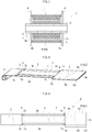
FIG. 2 is a schematic perspective view of a state in which a film body according to the first embodiment starts to be taken up by a winding core. -
FIG. 3 is a schematic plan view of a state in which the film body according to the first embodiment is developed. -
FIG. 4 is a schematic sectional view of a glass roll according to a second embodiment of the present invention. -
FIG. 5 is a schematic perspective view of a state in which a film body according to the second embodiment starts to be taken up by a winding core. -
FIG. 6 is a schematic plan view of a state in which the film body according to the second embodiment is developed. -
FIG. 7 is a schematic perspective view of a state in the course of taking up a film body of a glass roll according to a third embodiment of the present invention by a winding core. -
FIG. 8 is a schematic plan view of a state in which a film body according to a fourth embodiment of the present invention is developed. -
FIG. 9 is a schematic plan view of a state in which a film body according to a fifth embodiment of the present invention is developed. -
FIG. 10 is a schematic plan view of a state in which a film body according to a sixth embodiment of the present invention is developed. -
FIG. 11 is a schematic side view for illustrating a situation in which the film body according to the fifth embodiment or the sixth embodiment in a state of being taken up by a winding core is unwound therefrom. - Embodiments of the present invention are described be low with reference to the drawings.
-
FIG. 1 is a schematic sectional view of a glass roll according to a first embodiment of the present invention. Aglass roll 1 comprises: awinding core 2; a film body F comprising aglass film 3,lead films displacement prevention film 6, and ascattering prevention film 7; and a pair offlanges core 2. The film body F has a strip shape in which a longitudinal direction corresponds to a take-up direction. The same applies to theglass film 3. Thescattering prevention film 7 has a smaller width than theglass film 3. The pair offlanges core 2. The pair offlanges - In this embodiment, the winding
core 2 has a cylindrical shape . However, the shape of the windingcore 2 is not limited thereto, and the windingcore 2 may have, for example, a solid columnar shape. In addition, theflange 8 is detachable from the windingcore 2. However, the manner in which theflange 8 is mounted to the windingcore 2 is not limited thereto, and theflange 8 may remain fixed to the windingcore 2. - As illustrated in
FIG. 2 and FIG. 3 , the film body F comprises thedisplacement prevention film 6 on atermination end portion 3a side of theglass film 3 in the take-up direction, thedisplacement prevention film 6 being detachable from thelead film 4. Thedisplacement prevention film 6 comprises awide portion 6a having a larger width than theglass film 3. In this embodiment, thewide portion 6a of thedisplacement prevention film 6 corresponds to an entire region of thedisplacement prevention film 6 in the take-up direction, but may be part of the region of thedisplacement prevention film 6 in the take-up direction. An entire region of thelead film 4 in the take-up direction has a smaller width than thewide portion 6a of thedisplacement prevention film 6. - As illustrated in
FIG. 1 , thedisplacement prevention film 6 is arranged under a state in which both endportions wide portion 6a in the width direction protrude with respect to bothend portions glass film 3 in the width direction. The pair offlanges wide portion 6a in the width direction. Both theend portions wide portion 6a in the width direction are in a state of abutting on the pair offlanges flanges - As illustrated in
FIG. 2 and FIG. 3 , thedisplacement prevention film 6 is attached to thelead film 4 under a state in which thedisplacement prevention film 6 overlaps with thelead film 4, and an overlapping region of thedisplacement prevention film 6 with thelead film 4 is bonded to thelead film 4. In this embodiment, thelead film 4 and thedisplacement prevention film 6 may have the same size in the take-up direction, but may have different sizes. In addition, end surfaces ofend portions lead film 4 in the take-up direction are located at the same positions in the take-up direction as end surfaces ofend portions displacement prevention film 6 in the take-up direction, respectively, but may be located at different positions in the take-up direction. - In this embodiment, the
displacement prevention film 6 is bonded to thelead film 4 with an elastic adhesive, but other adhesives, such as an acrylic adhesive, a silicon-based adhesive, and a rubber-based adhesive, may be used. As the adhesive, an adhesive with which a bonded portion between thedisplacement prevention film 6 and thelead film 4 can be separated again is used. - The
lead films end portions glass film 3 in the longitudinal direction (take-up direction), respectively, with a connecting tape 9 (resin member) . - The
lead film 4 is a member to be loaded into a treatment device in advance of theglass film 3 in a roll-to-roll method so that theglass film 3 is prevented from being damaged, and thelead film 5 is a member to be loaded into the treatment device after theglass film 3 so that even a termination end of theglass film 3 to be unwound from theglass roll 1 can be treated. - The
termination end portion 3a of theglass film 3 in the take-up direction and thestart end portion 4a of thelead film 4 in the take-up direction, thelead film 4 being on the termination end portion side of theglass film 3 in the take-up direction, are in a state of not overlapping with each other but butting each other, or in a state of facing each other with a gap therebetween. Thetermination end portion 3a of theglass film 3 in the take-up direction and thestart end portion 4a of thelead film 4 in the take-up direction are connected to each other by bonding the connectingtape 9 to thetermination end portion 3a and thestart end portion 4a so that the connectingtape 9 straddles both the portions. - The
start end portion 3c of theglass film 3 in the take-up direction and atermination end portion 5a of thelead film 5 in the take-up direction, thelead film 5 being on a start end portion side of theglass film 3 in the take-up direction, are in a state of not overlapping with each other but butting each other, or in a state of facing each other with a gap therebetween. Thestart end portion 3c of theglass film 3 in the take-up direction and thetermination end portion 5a of thelead film 5 in the take-up direction are connected to each other by bonding the connectingtape 9 to thestart end portion 3c and thetermination end portion 5a so that the connectingtape 9 straddles both the portions. - In addition, the
scattering prevention film 7 is attached to a middle portion on one surface of theglass film 3 in the width direction along the longitudinal direction (take-up direction). Bothend portions scattering prevention film 7 in the longitudinal direction each overlap with the connectingtape 9. - The
scattering prevention film 7 is attached to a surface of theglass film 3 to be on an outer peripheral side of theglass roll 1 after theglass film 3 is taken up. Thescattering prevention film 7 may be interposed so as to be brought into contact with a surface of theglass film 3 to be on an inner peripheral side of theglass roll 1 after theglass film 3 is taken up. The connectingtapes 9 are attached to the surface of theglass film 3 and surfaces of thelead films glass roll 1 after theglass film 3 and thelead films displacement prevention film 6 overlaps with the surface of thelead film 4 to be on the outer peripheral side of theglass roll 1 after thelead film 4 is taken up. - The
glass film 3 is formed by an overflow down-draw method to have a thickness of from 1 µm to 200 µm (preferably from 10 µm to 100 µm). The reason why the glass film is set to have such a thickness is because, with the thickness within the above-mentioned numerical range, appropriate flexibility and strength can be imparted to theglass film 3 and no trouble arises at the time of winding. In other words, when the thickness of theglass film 3 is less than 1 µm, handling of the glass film is troublesome because of lack of strength. When the thickness of theglass film 3 exceeds 200 µm, satisfactory flexibility is not obtained, which leads to a problem in that a winding radius is extremely and inevitably increased. - A width of the
glass film 3 is preferably 100 mm or more, more preferably 300 mm or more, still more preferably 500 mm or more. Theglass film 3 is used for a wide variety of devices including a small-screen display, such as a mobile phone with a small size, and a large-screen display, such as a television set with a large size, and hence it is preferred that the width of theglass film 3 be finally selected as needed depending on a size of a substrate of a device to be used. - As a glass composition of the
glass film 3, there can be used various glass compositions of silicate glass and the like, such as silica glass and borosilicate glass. However, it is preferred to use non-alkali glass. The reason is as follows. When theglass film 3 contains an alkali component, a so-called too-abundant soda phenomenon occurs so that the glass film is structurally weathered. When theglass film 3 is curved, there is a risk in that the glass film is prone to break from a portion that is structurally weathered over time. Herein, the non-alkali glass refers to glass that does not substantially contain an alkali component, specifically, glass containing an alkali metal oxide of 1,000 ppm or less (preferably of 500 ppm or less, more preferably of 300 ppm or less). - In addition, in view of ensuring strength of the
glass film 3, it is preferred that at least each end surface in the width direction of theglass film 3 include a cut surface which is cut by laser splitting. With this configuration, the each end surface in the width direction of theglass film 3 has a cross-section with high strength free from defects causing breakage, such as microcracks . Specifically, when utilizing the laser splitting, without being subjected to polishing or the like after the cutting, the each end surface in the width direction of theglass film 3 may have an arithmetic average roughness Ra (compliant to JIS B0601:2001) of 0.1 µm or less (preferably 0.05 µm or less). - A thickness and a width of each of the
lead films glass film 3, it is preferred that the lead film have substantially the same thickness and width as those of theglass film 3. - Specifically, the thicknesses of the
lead films lead films glass film 3, and are each particularly preferably substantially the same as the width of theglass film 3 in consideration of loading into the treatment device. Thelead films glass film 3, and hence it is preferred to finally decide the thicknesses of thelead films lead films - As materials for the
lead films displacement prevention film 6 described below are given. A material difficult to stretch is preferably used, and a polyethylene terephthalate film (PET film) is preferably used. A metal film may be used, and in this case, aluminum, copper, or the like may be used as the metal. - The thickness of the
displacement prevention film 6 is not particularly limited, but is preferably about the same as the thickness of theglass film 3. Specifically, the thickness of thedisplacement prevention film 6 is preferably from 1 µm to 200 µm. - The width of the
displacement prevention film 6 is larger than the width of theglass film 3 by from 5 mm to 50 mm (preferably from 10 mm to 30 mm) in order to achieve the object of preventing winding displacement of theglass film 3. - As a material for the
displacement prevention film 6, for example, an organic resin film (synthetic resin film), such as an ionomer film, a polyethylene film, a polypropylene film, a polyvinyl chloride film, a polyvinylidene chloride film, a polyvinyl alcohol film, a polyester film, a polycarbonate film, a polystyrene film, a polyacrylonitrile film, an ethylene-vinyl acetate copolymer film, an ethylene-vinyl alcohol copolymer film, an ethylene-methacrylic acid copolymer film, a nylon (registered trademark) film (polyamide film), a polyimide film, or cellophane, may be used. Further, from the viewpoint of ensuring cushioning performance and strength at the same time, a foamed resin film, such as a sheet made of a polyethylene foamed resin, is preferably used as thedisplacement prevention film 6, and from the viewpoint of ensuring strength, a polyethylene terephthalate film (PET film) is preferably used as thedisplacement prevention film 6. - The
scattering prevention film 7 is a member for preventing scattering of broken pieces of theglass film 3 even when theglass film 3 is broken. In this embodiment, thescattering prevention film 7 comprises a support layer without a pressure-sensitive adhesive property and a pressure-sensitive adhesive layer for attachment to theglass film 3 formed on one surface of the support layer. - The thickness of the
scattering prevention film 7 is not particularly limited, but is preferably about the same as the thickness of theglass film 3 because thescattering prevention film 7 is generally attached to a surface of theglass film 3. Specifically, the thickness of thescattering prevention film 7 is preferably from 1 µm to 8 mm. - When the
scattering prevention film 7 covers both theend portions glass film 3 in the width direction, there is a risk in that both theend portions glass film 3 in the width direction are not recognized in, for example, a conveying device, and positioning of theglass film 3 or the like becomes difficult. Therefore, the width of thescattering prevention film 7 is smaller than the width of theglass film 3 by from 1 mm to 30 mm (preferably from 5 mm to 10 mm). - As a material for the support layer of the
scattering prevention film 7, the same materials as in the case of thedisplacement prevention film 6 described above are given. As a material for the pressure-sensitive adhesive layer of thescattering prevention film 7, there are given, for example, an elastic adhesive, an acrylic adhesive, a silicon-based adhesive, and a rubber-based adhesive. As the adhesive, an adhesive with which a bonded portion between thescattering prevention film 7 and theglass film 3 can be separated again is used. Thescattering prevention film 7 includes a mode in which thescattering prevention film 7 is formed only of the support layer without the pressure-sensitive adhesive layer, and in this case, has the same function as a slip sheet. - In this embodiment, the connecting
tape 9 comprises a support layer without a pressure-sensitive adhesive property and a pressure-sensitive adhesive layer for attachment to theglass film 3 and thelead films tape 9 in the take-up direction and the width direction of theglass film 3 and thelead films - The thickness of the support layer of the connecting
tape 9 is preferably 150 µm or less, more preferably 100 µm or less. Moreover, the thickness of the support layer is preferably 10 µm or more, more preferably 30 µm or more. When the thickness of the support layer is less than 10 µm, strength may be impaired, and when the thickness of the support layer is more than 150 µm, flexibility may be insufficient, or a load may be applied to theglass film 3 depending on the thickness of the support layer after theglass film 3 is taken up. - The thickness of the pressure-sensitive adhesive layer of the connecting
tape 9 is appropriately set in consideration of adhesion strength, and is, for example, from 10 µm to 15 µm. In addition, when the thickness of the connectingtape 9 is large, drain after washing with water becomes poor owing to a step between the connectingtape 9 and theglass film 3 or each of thelead films - Materials for the support layer and the pressure-sensitive adhesive layer of the connecting
tape 9 are not particularly limited, and may be materials which have hitherto been used. An example of the material for the support layer is a resin, such as polyester. Examples of the material for the pressure-sensitive adhesive layer include an elastic adhesive, an acrylic adhesive, a silicon-based adhesive, and a rubber-based adhesive. As the adhesive, an adhesive with which a bonded portion between the connectingtape 9 and each of thelead films glass film 3 can be separated again is used. - Next, a method of producing the
glass roll 1 is described. - First, each of the
lead films glass film 3 with the connectingtape 9. Then, thescattering prevention film 7 is attached to the glass film. After that, thedisplacement prevention film 6 is attached to thelead film 4 with an elastic adhesive. Thus, the film body F is completed. - Next, the film body F is taken up into a roll shape by the winding
core 2. After that, the pair offlanges core 2. Thus, theglass roll 1 is completed. - When the
glass roll 1 is used, thedisplacement prevention film 6 is detached from the film body F, and the residual film body F is introduced into a treatment device. - The
glass roll 1 according to this embodiment having the above-mentioned configuration can exhibit the following effects. - Even when winding displacement nearly occurs at the
termination end portion 3a of theglass film 3 in the take-up direction during transport of theglass roll 1, the occurrence of the winding displacement can be prevented because thewide portion 6a of thedisplacement prevention film 6 is in a state of abutting on theflange 8 or abuts on theflange 8. That is, according to theglass roll 1 of this embodiment, the winding displacement during transport can be prevented even when thescattering prevention film 7 having a smaller width than theglass film 3 is used. - In addition, the
displacement prevention film 6, which is detachable from thelead film 4, is on thetermination end portion 3a side of theglass film 3 in the take-up direction, and is on a start end portion side of the film body F at the time of unwinding theglass film 3 from theglass roll 1. Accordingly, it is easy to detach thedisplacement prevention film 6 from the film body F when theglass film 3 is used by being unwound from theglass roll 1. - Next, a glass roll according to a second embodiment of the present invention is described with reference to
FIG. 4 to FIG. 6 . - A
glass roll 1 of this embodiment differs from the glass roll of the first embodiment in that adisplacement prevention film 6 is attached to alead film 4 under a state in which thedisplacement prevention film 6 does not overlap with thelead film 4. Specifically, atermination end portion 4b of thelead film 4 in a take-up direction and astart end portion 6c of thedisplacement prevention film 6 in the take-up direction are in a state of butting each other, or in a state of facing each other with a gap therebetween. Moreover, thetermination end portion 4b of thelead film 4 in the take-up direction and thestart end portion 6c of thedisplacement prevention film 6 in the take-up direction are connected to each other by bonding a connectingtape 9 to thetermination end portion 4b and thestart end portion 6c so that the connectingtape 9 straddles both the portions. Other configurations are the same as in the first embodiment. Therefore, like configurations are denoted by like reference symbols, and description thereof is omitted. - Next, a glass roll according to a third embodiment of the present invention is described with reference to
FIG. 7 . - In this embodiment, unlike the first embodiment, a
displacement prevention film 6 overlaps with a surface of alead film 4 to be on an inner peripheral side of aglass roll 1 after the leadfilm4 istakenup. In addition, unlike the second embodiment, thelead film 4 and thedisplacement prevention film 6 are connected to each other under a state in which an end portion of thelead film 4 and an end portion of thedisplacement prevention film 6 overlap with each other by bonding a connectingtape 9 to the end portions so that the connectingtape 9 straddles both the portions. - In addition, in this embodiment, unlike the above-mentioned embodiments, the
lead film 4 overlaps a surface of theglass film 3 to be on the inner peripheral side of theglass roll 1 after theglass film 3 is taken up. Moreover, theglass film 3 and thelead film 4 are connected to each other under a state in which an end portion of theglass film 3 and an end portion of thelead film 4 overlap with each other by bonding a connectingtape 9 to the end portions so that the connectingtape 9 straddles both the portions. In addition, the connectingtapes 9 are each attached to a surface of the film body F to be on the inner peripheral side of theglass roll 1 after the film body F is taken up. Atermination end portion 7b of ascattering prevention film 7 in a take-up direction is located at the same position in the take-up direction (longitudinal direction) as atermination end portion 3a of theglass film 3 in the take-up direction. Other configurations are the same as in the above-mentioned embodiments. Therefore, like configurations are denoted by like reference symbols, and description thereof is omitted. - Next, a glass roll according to a fourth embodiment of the present invention is described with reference to
FIG. 8 . - In this embodiment, unlike the above-mentioned embodiments, a
scattering prevention film 7 extends from aglass film 3 to a middle portion of each oflead films end portions scattering prevention film 7 in the longitudinal direction are located in the middle portions of thelead films scattering prevention film 7 does not have a pressure-sensitive adhesive property, but may be used when thescattering prevention film 7 has a pressure-sensitive adhesive property. Other configurations are the same as in the second embodiment. Therefore, like configurations are denoted by like reference symbols, and description thereof is omitted. - Next, a glass roll according to a fifth embodiment of the present invention is described with reference to
FIG. 9 . - In this embodiment, unlike the above-mentioned embodiments, a
displacement prevention film 6 is attached not to alead film 4, but to ascattering prevention film 7. Specifically, thescattering prevention film 7 on atermination end portion 7b side in a take-up direction extends from aglass film 3 and passes thelead film 4 to a position beyond atermination end portion 4b of thelead film 4 in the take-up direction. Moreover, atermination end portion 7b of thescattering prevention film 7 in the take-up direction and astart end portion 6c of thedisplacement prevention film 6 in the take-up direction are in a state of butting each other, or in a state of facing each other with a gap therebetween. Moreover, thetermination end portion 7b of thescattering prevention film 7 in the take-up direction and thestart end portion 6c of thedisplacement prevention film 6 in the take-up direction are connected to each other by bonding a connectingtape 9 to thetermination end portion 7b and thestart end portion 6c so that the connectingtape 9 straddles both the portions. Thetermination end portion 4b of thelead film 4 in the take-up direction and thestart end portion 6c of thedisplacement prevention film 6 in the take-up direction are in a state of facing each other with a gap therebetween. Other configurations are the same as in the fourth embodiment. Therefore, like configurations are denoted by like reference symbols, and description thereof is omitted. - Next, a glass roll according to a sixth embodiment of the present invention is described with reference to
FIG. 10 . - In this embodiment, as in the fifth embodiment, a
start end portion 6c of adisplacement prevention film 6 in a take-up direction is attached to atermination end portion 7b of ascattering prevention film 7 in the take-up direction. However, this embodiment differs from the fifth embodiment in that atermination end portion 6d of thedisplacement prevention film 6 in the take-up direction is located at the same position in the take-up direction as atermination end portion 4b of alead film 4 in the take-up direction. - In this embodiment, the
displacement prevention film 6 may or may not be bonded to thelead film 4 with an adhesive. When thedisplacement prevention film 6 is bonded to thelead film 4 with an adhesive, an adhesive with which a bonded portion between thedisplacement prevention film 6 and thelead film 4 can be separated again is used as the adhesive. Other configurations are the same as in the fifth embodiment. Therefore, like configurations are denoted by like reference symbols, and description thereof is omitted. - In the sixth embodiment, the following effects can be exhibited as compared to the fifth embodiment.
- When the
displacement prevention film 6 is attached to thescattering prevention film 7, and thelead film 4 is attached to theglass film 3 as in the fifth embodiment and the sixth embodiment, at the time of unwinding the film body F in a state of having been taken up by the windingcore 2, thescattering prevention film 7 is peeled off from theglass film 3 with aroller 10, and thescattering prevention film 7 is taken up by a windingcore 11 with thedisplacement prevention film 6 at the forefront, as illustrated inFIG. 11 . Meanwhile, theglass film 3 from which thescattering prevention film 7 has been peeled off is introduced into a predetermined treatment device with thelead film 4 at the forefront. - As described above, at the time of unwinding the film body F, first, it is required to introduce the
displacement prevention film 6 attached to thescattering prevention film 7 to a windingcore 11 side, and meanwhile, introduce thelead film 4 attached to theglass film 3 to a treatment device side. That is, it is required to separate thedisplacement prevention film 6 and thelead film 4 in order to introduce thedisplacement prevention film 6 and thelead film 4 in different directions. - At this time, when the
termination end portion 6d of thedisplacement prevention film 6 is located at a greatly different position in the take-up direction from thetermination end portion 4b of thelead film 4 as in the fifth embodiment, it becomes difficult to separate thedisplacement prevention film 6 and thelead film 4 from each other. - In contrast to this, when the
termination end portion 6d of thedisplacement prevention film 6 is located at the same position in the take-up direction as thetermination end portion 4b of thelead film 4 as in the sixth embodiment, it is easy to separate thedisplacement prevention film 6 and thelead film 4 from each other. - The present invention is not limited to the above-mentioned embodiments, and various modifications may be made within the scope of the technical idea of the present invention. For example, while the
displacement prevention film 6 is attached to thelead film 4 or thescattering prevention film 7 in each of the above-mentioned embodiments, thedisplacement prevention film 6 may be attached to theglass film 3. - In addition, while the
glass film 3 and each of thelead films tape 9 to these components in each of the above-mentioned embodiments, theglass film 3 and each of thelead films tape 9 may be used. In addition, as the adhesive, an adhesive with which the bonded portion between theglass film 3 and each of thelead films - In addition, in the above-mentioned embodiments, description is made of the case where the
glass film 3 is formed by the overflow down-draw method. However, theglass film 3 may be formed by a down-draw method, such as a slot down-draw method or a redraw method. When using the down-draw method in this way, unlike a case of forming theglass film 3 by a float method, the surface of theglass film 3 is not contaminated by tin or the like. Thus, there is an advantage that theglass film 3 can be used under a state in which the surface of theglass film 3 remains unpolished. Theglass roll 1 is targeted for theglass film 3 having a small thickness, and hence it is also very advantageous to use the glass film with a surface remaining unpolished in terms of reducing a risk of breakage of theglass film 3. In view of ensuring smoothness of the surface of theglass film 3, it is preferred to adopt the overflow down-draw method or the redraw method among the down-draw methods. -
- 1
- glass roll
- 2
- winding core
- 3
- glass film
- 3a
- termination end portion
- 4
- lead film
- 4b
- termination end portion
- 6
- displacement prevention film
- 6a
- wide portion
- 6c
- start end portion
- 7
- scattering prevention film
- 8
- flange
- F
- film body
Claims (4)
- A glass roll, comprising:a winding core;a film body, which is taken up into a roll shape by the winding core, and comprises a glass film and a scattering prevention film having a smaller width than the glass film; andflanges, which are mounted to the winding core, and are arranged on both sides of the film body in a width direction,wherein the film body comprises a detachable displacement prevention film on a termination end portion side of the glass film in a take-up direction, andwherein the displacement prevention film comprises a wide portion having a lager width than the glass film.
- The glass roll according to claim 1,
wherein the film body comprises a lead film having a smaller width than the wide portion on the termination end portion side, and
wherein the displacement prevention film is attached to the lead film. - The glass roll according to claim 2,
wherein the displacement prevention film is in a state of overlapping with the lead film, and
wherein an overlapping region of the displacement prevention film with the lead film is bonded to the lead film. - The glass roll according to claim 2 or 3, wherein a start end portion of the displacement prevention film in the take-up direction is attached to a termination end portion of the lead film in the take-up direction.
Applications Claiming Priority (2)
| Application Number | Priority Date | Filing Date | Title |
|---|---|---|---|
| JP2016203427 | 2016-10-17 | ||
| PCT/JP2017/037269 WO2018074383A1 (en) | 2016-10-17 | 2017-10-13 | Glass roll |
Publications (3)
| Publication Number | Publication Date |
|---|---|
| EP3527521A1 true EP3527521A1 (en) | 2019-08-21 |
| EP3527521A4 EP3527521A4 (en) | 2020-07-01 |
| EP3527521B1 EP3527521B1 (en) | 2021-03-03 |
Family
ID=62018671
Family Applications (1)
| Application Number | Title | Priority Date | Filing Date |
|---|---|---|---|
| EP17861227.1A Active EP3527521B1 (en) | 2016-10-17 | 2017-10-13 | Glass roll |
Country Status (7)
| Country | Link |
|---|---|
| US (1) | US11724901B2 (en) |
| EP (1) | EP3527521B1 (en) |
| JP (1) | JP6853963B2 (en) |
| KR (1) | KR102365869B1 (en) |
| CN (1) | CN109311620B (en) |
| TW (1) | TWI733926B (en) |
| WO (1) | WO2018074383A1 (en) |
Cited By (2)
| Publication number | Priority date | Publication date | Assignee | Title |
|---|---|---|---|---|
| WO2024107414A1 (en) * | 2022-11-14 | 2024-05-23 | Corning Incorporated | Glass roll |
| WO2024253987A1 (en) * | 2023-06-07 | 2024-12-12 | Corning Incorporated | Glass roll |
Families Citing this family (7)
| Publication number | Priority date | Publication date | Assignee | Title |
|---|---|---|---|---|
| US11604374B2 (en) * | 2017-12-26 | 2023-03-14 | Saturn Licensing Llc | Display apparatus |
| FR3087471B1 (en) * | 2018-10-23 | 2020-11-06 | Saint Gobain | PROCESS FOR OBTAINING AN INSULATING GLAZING |
| JP7194571B2 (en) * | 2018-12-04 | 2022-12-22 | 日東電工株式会社 | Optical film winding core, optical film roll body, and continuous supply method for optical film |
| JP7192753B2 (en) * | 2019-12-09 | 2022-12-20 | 日本電気硝子株式会社 | glass roll |
| JP7377454B2 (en) * | 2019-12-09 | 2023-11-10 | 日本電気硝子株式会社 | glass roll |
| KR102824146B1 (en) * | 2020-07-17 | 2025-06-23 | 코닝 인코포레이티드 | A glass roll |
| CN113581649B (en) * | 2021-07-14 | 2023-02-10 | 石狮市喜运达包装用品有限公司 | High-toughness packaging belt and preparation method thereof |
Family Cites Families (20)
| Publication number | Priority date | Publication date | Assignee | Title |
|---|---|---|---|---|
| US4455076A (en) * | 1982-09-13 | 1984-06-19 | Minnesota Mining & Manufacturing Company | Film supply cassette for camera processor |
| DE3671303D1 (en) * | 1986-01-20 | 1990-06-21 | Agfa Gevaert Nv | LIGHT-TIGHTLY PACKED REEL OF LIGHT-SENSITIVE MATERIAL. |
| JP2010132532A (en) * | 2008-10-01 | 2010-06-17 | Nippon Electric Glass Co Ltd | Glass roll and method for producing the same |
| JP5532506B2 (en) | 2008-10-01 | 2014-06-25 | 日本電気硝子株式会社 | Glass roll |
| JP5532507B2 (en) | 2008-10-01 | 2014-06-25 | 日本電気硝子株式会社 | Glass roll and glass roll processing method |
| JP5691148B2 (en) * | 2008-10-01 | 2015-04-01 | 日本電気硝子株式会社 | Glass roll, glass roll manufacturing apparatus, and glass roll manufacturing method |
| JP5510880B2 (en) * | 2009-03-26 | 2014-06-04 | 日本電気硝子株式会社 | Glass film laminate, glass roll of the laminate, and method for producing glass roll |
| US20110023548A1 (en) * | 2009-07-29 | 2011-02-03 | Garner Sean M | Glass substrate comprising an edge web portion |
| JP5645123B2 (en) * | 2010-01-12 | 2014-12-24 | 日本電気硝子株式会社 | Glass film laminate, method for producing the same, and method for producing glass film |
| WO2012099073A1 (en) * | 2011-01-20 | 2012-07-26 | 旭硝子株式会社 | Glass roll, glass roll manufacturing apparatus, and glass roll manufacturing method |
| JP5783443B2 (en) * | 2011-03-14 | 2015-09-24 | 日本電気硝子株式会社 | GLASS ROLL AND GLASS ROLL MANUFACTURING METHOD |
| JP6024659B2 (en) * | 2011-07-19 | 2016-11-16 | 旭硝子株式会社 | Thin glass winder and storage device |
| JP2013035159A (en) * | 2011-08-04 | 2013-02-21 | Dainippon Printing Co Ltd | Glass film laminate, glass film laminate roll, glass film laminate with pixel for color filter, and method for producing glass film laminate |
| JP6314136B2 (en) * | 2012-07-02 | 2018-04-18 | コーニング インコーポレイテッド | Method for processing glass substrate and glass fixture |
| JP2014113687A (en) * | 2012-12-06 | 2014-06-26 | Nitto Denko Corp | Thin glass laminate |
| DE102014221245A1 (en) * | 2014-10-20 | 2016-04-21 | Tesa Se | Thin glass foil composite web with stiffening strips |
| JP6699159B2 (en) * | 2015-12-17 | 2020-05-27 | 日本電気硝子株式会社 | Glass roll and manufacturing method thereof |
| JP6883282B2 (en) * | 2017-11-27 | 2021-06-09 | 日本電気硝子株式会社 | Glass roll manufacturing method |
| US11639046B2 (en) * | 2018-04-25 | 2023-05-02 | Nitto Denko Corporation | Glass film-resin composite |
| EP3785901B1 (en) * | 2018-04-25 | 2024-10-09 | Nitto Denko Corporation | (glass film)-resin complex |
-
2017
- 2017-10-13 WO PCT/JP2017/037269 patent/WO2018074383A1/en not_active Ceased
- 2017-10-13 KR KR1020187031608A patent/KR102365869B1/en active Active
- 2017-10-13 CN CN201780037890.5A patent/CN109311620B/en active Active
- 2017-10-13 US US16/323,017 patent/US11724901B2/en active Active
- 2017-10-13 JP JP2018546306A patent/JP6853963B2/en active Active
- 2017-10-13 EP EP17861227.1A patent/EP3527521B1/en active Active
- 2017-10-17 TW TW106135402A patent/TWI733926B/en active
Cited By (2)
| Publication number | Priority date | Publication date | Assignee | Title |
|---|---|---|---|---|
| WO2024107414A1 (en) * | 2022-11-14 | 2024-05-23 | Corning Incorporated | Glass roll |
| WO2024253987A1 (en) * | 2023-06-07 | 2024-12-12 | Corning Incorporated | Glass roll |
Also Published As
| Publication number | Publication date |
|---|---|
| CN109311620A (en) | 2019-02-05 |
| TW201827310A (en) | 2018-08-01 |
| EP3527521B1 (en) | 2021-03-03 |
| JPWO2018074383A1 (en) | 2019-08-08 |
| TWI733926B (en) | 2021-07-21 |
| US11724901B2 (en) | 2023-08-15 |
| KR20190064532A (en) | 2019-06-10 |
| EP3527521A4 (en) | 2020-07-01 |
| US20190177104A1 (en) | 2019-06-13 |
| CN109311620B (en) | 2021-03-19 |
| WO2018074383A1 (en) | 2018-04-26 |
| KR102365869B1 (en) | 2022-02-22 |
| JP6853963B2 (en) | 2021-04-07 |
Similar Documents
| Publication | Publication Date | Title |
|---|---|---|
| EP3527521B1 (en) | Glass roll | |
| US10562727B2 (en) | Glass roll and method of processing glass roll | |
| EP2548730B1 (en) | Glass resin laminate, glass roll for taking up same and glass roll manufacturing method | |
| US10781036B2 (en) | Glass roll with a separable protective sheet | |
| JP5806665B2 (en) | Glass substrate having edge web portion | |
| US20120237779A1 (en) | Glass roll and manufacturing method for glass roll | |
| CN114555501B (en) | Glass roll | |
| JP2015134705A (en) | Film-like connector, and glass roll | |
| TW202019801A (en) | Glass film laminate roll |
Legal Events
| Date | Code | Title | Description |
|---|---|---|---|
| STAA | Information on the status of an ep patent application or granted ep patent |
Free format text: STATUS: THE INTERNATIONAL PUBLICATION HAS BEEN MADE |
|
| PUAI | Public reference made under article 153(3) epc to a published international application that has entered the european phase |
Free format text: ORIGINAL CODE: 0009012 |
|
| STAA | Information on the status of an ep patent application or granted ep patent |
Free format text: STATUS: REQUEST FOR EXAMINATION WAS MADE |
|
| 17P | Request for examination filed |
Effective date: 20190205 |
|
| AK | Designated contracting states |
Kind code of ref document: A1 Designated state(s): AL AT BE BG CH CY CZ DE DK EE ES FI FR GB GR HR HU IE IS IT LI LT LU LV MC MK MT NL NO PL PT RO RS SE SI SK SM TR |
|
| AX | Request for extension of the european patent |
Extension state: BA ME |
|
| DAV | Request for validation of the european patent (deleted) | ||
| DAX | Request for extension of the european patent (deleted) | ||
| A4 | Supplementary search report drawn up and despatched |
Effective date: 20200529 |
|
| RIC1 | Information provided on ipc code assigned before grant |
Ipc: B32B 17/06 20060101ALI20200525BHEP Ipc: B65H 75/28 20060101ALI20200525BHEP Ipc: C03B 17/06 20060101ALI20200525BHEP Ipc: B65H 75/14 20060101ALI20200525BHEP Ipc: B65D 85/672 20060101ALI20200525BHEP Ipc: B65H 18/28 20060101ALI20200525BHEP Ipc: B65D 85/48 20060101ALI20200525BHEP Ipc: B65H 75/02 20060101AFI20200525BHEP |
|
| RIC1 | Information provided on ipc code assigned before grant |
Ipc: B65H 75/14 20060101ALI20201030BHEP Ipc: B65D 85/672 20060101ALI20201030BHEP Ipc: B65H 18/28 20060101ALI20201030BHEP Ipc: B32B 1/00 20060101ALI20201030BHEP Ipc: B65D 85/48 20060101ALI20201030BHEP Ipc: B32B 17/06 20060101ALI20201030BHEP Ipc: B32B 7/12 20060101ALI20201030BHEP Ipc: B65H 75/02 20060101AFI20201030BHEP Ipc: B32B 3/08 20060101ALI20201030BHEP Ipc: B65H 75/28 20060101ALI20201030BHEP Ipc: C03B 17/06 20060101ALI20201030BHEP |
|
| GRAP | Despatch of communication of intention to grant a patent |
Free format text: ORIGINAL CODE: EPIDOSNIGR1 |
|
| STAA | Information on the status of an ep patent application or granted ep patent |
Free format text: STATUS: GRANT OF PATENT IS INTENDED |
|
| INTG | Intention to grant announced |
Effective date: 20201223 |
|
| GRAS | Grant fee paid |
Free format text: ORIGINAL CODE: EPIDOSNIGR3 |
|
| GRAA | (expected) grant |
Free format text: ORIGINAL CODE: 0009210 |
|
| STAA | Information on the status of an ep patent application or granted ep patent |
Free format text: STATUS: THE PATENT HAS BEEN GRANTED |
|
| AK | Designated contracting states |
Kind code of ref document: B1 Designated state(s): AL AT BE BG CH CY CZ DE DK EE ES FI FR GB GR HR HU IE IS IT LI LT LU LV MC MK MT NL NO PL PT RO RS SE SI SK SM TR |
|
| REG | Reference to a national code |
Ref country code: GB Ref legal event code: FG4D |
|
| REG | Reference to a national code |
Ref country code: AT Ref legal event code: REF Ref document number: 1366998 Country of ref document: AT Kind code of ref document: T Effective date: 20210315 Ref country code: CH Ref legal event code: EP |
|
| REG | Reference to a national code |
Ref country code: DE Ref legal event code: R096 Ref document number: 602017034078 Country of ref document: DE |
|
| REG | Reference to a national code |
Ref country code: IE Ref legal event code: FG4D |
|
| REG | Reference to a national code |
Ref country code: LT Ref legal event code: MG9D |
|
| PG25 | Lapsed in a contracting state [announced via postgrant information from national office to epo] |
Ref country code: FI Free format text: LAPSE BECAUSE OF FAILURE TO SUBMIT A TRANSLATION OF THE DESCRIPTION OR TO PAY THE FEE WITHIN THE PRESCRIBED TIME-LIMIT Effective date: 20210303 Ref country code: GR Free format text: LAPSE BECAUSE OF FAILURE TO SUBMIT A TRANSLATION OF THE DESCRIPTION OR TO PAY THE FEE WITHIN THE PRESCRIBED TIME-LIMIT Effective date: 20210604 Ref country code: HR Free format text: LAPSE BECAUSE OF FAILURE TO SUBMIT A TRANSLATION OF THE DESCRIPTION OR TO PAY THE FEE WITHIN THE PRESCRIBED TIME-LIMIT Effective date: 20210303 Ref country code: NO Free format text: LAPSE BECAUSE OF FAILURE TO SUBMIT A TRANSLATION OF THE DESCRIPTION OR TO PAY THE FEE WITHIN THE PRESCRIBED TIME-LIMIT Effective date: 20210603 Ref country code: LT Free format text: LAPSE BECAUSE OF FAILURE TO SUBMIT A TRANSLATION OF THE DESCRIPTION OR TO PAY THE FEE WITHIN THE PRESCRIBED TIME-LIMIT Effective date: 20210303 Ref country code: BG Free format text: LAPSE BECAUSE OF FAILURE TO SUBMIT A TRANSLATION OF THE DESCRIPTION OR TO PAY THE FEE WITHIN THE PRESCRIBED TIME-LIMIT Effective date: 20210603 |
|
| REG | Reference to a national code |
Ref country code: NL Ref legal event code: MP Effective date: 20210303 |
|
| REG | Reference to a national code |
Ref country code: AT Ref legal event code: MK05 Ref document number: 1366998 Country of ref document: AT Kind code of ref document: T Effective date: 20210303 |
|
| PG25 | Lapsed in a contracting state [announced via postgrant information from national office to epo] |
Ref country code: SE Free format text: LAPSE BECAUSE OF FAILURE TO SUBMIT A TRANSLATION OF THE DESCRIPTION OR TO PAY THE FEE WITHIN THE PRESCRIBED TIME-LIMIT Effective date: 20210303 Ref country code: LV Free format text: LAPSE BECAUSE OF FAILURE TO SUBMIT A TRANSLATION OF THE DESCRIPTION OR TO PAY THE FEE WITHIN THE PRESCRIBED TIME-LIMIT Effective date: 20210303 Ref country code: RS Free format text: LAPSE BECAUSE OF FAILURE TO SUBMIT A TRANSLATION OF THE DESCRIPTION OR TO PAY THE FEE WITHIN THE PRESCRIBED TIME-LIMIT Effective date: 20210303 Ref country code: PL Free format text: LAPSE BECAUSE OF FAILURE TO SUBMIT A TRANSLATION OF THE DESCRIPTION OR TO PAY THE FEE WITHIN THE PRESCRIBED TIME-LIMIT Effective date: 20210303 |
|
| PG25 | Lapsed in a contracting state [announced via postgrant information from national office to epo] |
Ref country code: NL Free format text: LAPSE BECAUSE OF FAILURE TO SUBMIT A TRANSLATION OF THE DESCRIPTION OR TO PAY THE FEE WITHIN THE PRESCRIBED TIME-LIMIT Effective date: 20210303 |
|
| PG25 | Lapsed in a contracting state [announced via postgrant information from national office to epo] |
Ref country code: SM Free format text: LAPSE BECAUSE OF FAILURE TO SUBMIT A TRANSLATION OF THE DESCRIPTION OR TO PAY THE FEE WITHIN THE PRESCRIBED TIME-LIMIT Effective date: 20210303 Ref country code: AT Free format text: LAPSE BECAUSE OF FAILURE TO SUBMIT A TRANSLATION OF THE DESCRIPTION OR TO PAY THE FEE WITHIN THE PRESCRIBED TIME-LIMIT Effective date: 20210303 Ref country code: EE Free format text: LAPSE BECAUSE OF FAILURE TO SUBMIT A TRANSLATION OF THE DESCRIPTION OR TO PAY THE FEE WITHIN THE PRESCRIBED TIME-LIMIT Effective date: 20210303 Ref country code: CZ Free format text: LAPSE BECAUSE OF FAILURE TO SUBMIT A TRANSLATION OF THE DESCRIPTION OR TO PAY THE FEE WITHIN THE PRESCRIBED TIME-LIMIT Effective date: 20210303 |
|
| PG25 | Lapsed in a contracting state [announced via postgrant information from national office to epo] |
Ref country code: PT Free format text: LAPSE BECAUSE OF FAILURE TO SUBMIT A TRANSLATION OF THE DESCRIPTION OR TO PAY THE FEE WITHIN THE PRESCRIBED TIME-LIMIT Effective date: 20210705 Ref country code: RO Free format text: LAPSE BECAUSE OF FAILURE TO SUBMIT A TRANSLATION OF THE DESCRIPTION OR TO PAY THE FEE WITHIN THE PRESCRIBED TIME-LIMIT Effective date: 20210303 Ref country code: SK Free format text: LAPSE BECAUSE OF FAILURE TO SUBMIT A TRANSLATION OF THE DESCRIPTION OR TO PAY THE FEE WITHIN THE PRESCRIBED TIME-LIMIT Effective date: 20210303 Ref country code: IS Free format text: LAPSE BECAUSE OF FAILURE TO SUBMIT A TRANSLATION OF THE DESCRIPTION OR TO PAY THE FEE WITHIN THE PRESCRIBED TIME-LIMIT Effective date: 20210703 |
|
| REG | Reference to a national code |
Ref country code: DE Ref legal event code: R097 Ref document number: 602017034078 Country of ref document: DE |
|
| PLBE | No opposition filed within time limit |
Free format text: ORIGINAL CODE: 0009261 |
|
| STAA | Information on the status of an ep patent application or granted ep patent |
Free format text: STATUS: NO OPPOSITION FILED WITHIN TIME LIMIT |
|
| PG25 | Lapsed in a contracting state [announced via postgrant information from national office to epo] |
Ref country code: DK Free format text: LAPSE BECAUSE OF FAILURE TO SUBMIT A TRANSLATION OF THE DESCRIPTION OR TO PAY THE FEE WITHIN THE PRESCRIBED TIME-LIMIT Effective date: 20210303 Ref country code: AL Free format text: LAPSE BECAUSE OF FAILURE TO SUBMIT A TRANSLATION OF THE DESCRIPTION OR TO PAY THE FEE WITHIN THE PRESCRIBED TIME-LIMIT Effective date: 20210303 Ref country code: ES Free format text: LAPSE BECAUSE OF FAILURE TO SUBMIT A TRANSLATION OF THE DESCRIPTION OR TO PAY THE FEE WITHIN THE PRESCRIBED TIME-LIMIT Effective date: 20210303 |
|
| 26N | No opposition filed |
Effective date: 20211206 |
|
| PG25 | Lapsed in a contracting state [announced via postgrant information from national office to epo] |
Ref country code: SI Free format text: LAPSE BECAUSE OF FAILURE TO SUBMIT A TRANSLATION OF THE DESCRIPTION OR TO PAY THE FEE WITHIN THE PRESCRIBED TIME-LIMIT Effective date: 20210303 |
|
| PG25 | Lapsed in a contracting state [announced via postgrant information from national office to epo] |
Ref country code: IT Free format text: LAPSE BECAUSE OF FAILURE TO SUBMIT A TRANSLATION OF THE DESCRIPTION OR TO PAY THE FEE WITHIN THE PRESCRIBED TIME-LIMIT Effective date: 20210303 |
|
| PG25 | Lapsed in a contracting state [announced via postgrant information from national office to epo] |
Ref country code: IS Free format text: LAPSE BECAUSE OF FAILURE TO SUBMIT A TRANSLATION OF THE DESCRIPTION OR TO PAY THE FEE WITHIN THE PRESCRIBED TIME-LIMIT Effective date: 20210703 |
|
| REG | Reference to a national code |
Ref country code: CH Ref legal event code: PL |
|
| REG | Reference to a national code |
Ref country code: BE Ref legal event code: MM Effective date: 20211031 |
|
| GBPC | Gb: european patent ceased through non-payment of renewal fee |
Effective date: 20211013 |
|
| PG25 | Lapsed in a contracting state [announced via postgrant information from national office to epo] |
Ref country code: MC Free format text: LAPSE BECAUSE OF FAILURE TO SUBMIT A TRANSLATION OF THE DESCRIPTION OR TO PAY THE FEE WITHIN THE PRESCRIBED TIME-LIMIT Effective date: 20210303 |
|
| PG25 | Lapsed in a contracting state [announced via postgrant information from national office to epo] |
Ref country code: LU Free format text: LAPSE BECAUSE OF NON-PAYMENT OF DUE FEES Effective date: 20211013 Ref country code: GB Free format text: LAPSE BECAUSE OF NON-PAYMENT OF DUE FEES Effective date: 20211013 Ref country code: BE Free format text: LAPSE BECAUSE OF NON-PAYMENT OF DUE FEES Effective date: 20211031 |
|
| PG25 | Lapsed in a contracting state [announced via postgrant information from national office to epo] |
Ref country code: LI Free format text: LAPSE BECAUSE OF NON-PAYMENT OF DUE FEES Effective date: 20211031 Ref country code: CH Free format text: LAPSE BECAUSE OF NON-PAYMENT OF DUE FEES Effective date: 20211031 |
|
| PG25 | Lapsed in a contracting state [announced via postgrant information from national office to epo] |
Ref country code: FR Free format text: LAPSE BECAUSE OF NON-PAYMENT OF DUE FEES Effective date: 20211031 |
|
| PG25 | Lapsed in a contracting state [announced via postgrant information from national office to epo] |
Ref country code: IE Free format text: LAPSE BECAUSE OF NON-PAYMENT OF DUE FEES Effective date: 20211013 |
|
| PG25 | Lapsed in a contracting state [announced via postgrant information from national office to epo] |
Ref country code: CY Free format text: LAPSE BECAUSE OF FAILURE TO SUBMIT A TRANSLATION OF THE DESCRIPTION OR TO PAY THE FEE WITHIN THE PRESCRIBED TIME-LIMIT Effective date: 20210303 |
|
| PG25 | Lapsed in a contracting state [announced via postgrant information from national office to epo] |
Ref country code: HU Free format text: LAPSE BECAUSE OF FAILURE TO SUBMIT A TRANSLATION OF THE DESCRIPTION OR TO PAY THE FEE WITHIN THE PRESCRIBED TIME-LIMIT; INVALID AB INITIO Effective date: 20171013 |
|
| PG25 | Lapsed in a contracting state [announced via postgrant information from national office to epo] |
Ref country code: MK Free format text: LAPSE BECAUSE OF FAILURE TO SUBMIT A TRANSLATION OF THE DESCRIPTION OR TO PAY THE FEE WITHIN THE PRESCRIBED TIME-LIMIT Effective date: 20210303 |
|
| PG25 | Lapsed in a contracting state [announced via postgrant information from national office to epo] |
Ref country code: TR Free format text: LAPSE BECAUSE OF FAILURE TO SUBMIT A TRANSLATION OF THE DESCRIPTION OR TO PAY THE FEE WITHIN THE PRESCRIBED TIME-LIMIT Effective date: 20210303 |
|
| PG25 | Lapsed in a contracting state [announced via postgrant information from national office to epo] |
Ref country code: MT Free format text: LAPSE BECAUSE OF FAILURE TO SUBMIT A TRANSLATION OF THE DESCRIPTION OR TO PAY THE FEE WITHIN THE PRESCRIBED TIME-LIMIT Effective date: 20210303 |
|
| PGFP | Annual fee paid to national office [announced via postgrant information from national office to epo] |
Ref country code: DE Payment date: 20250902 Year of fee payment: 9 |