EP3527458A1 - Bogie and suspended vehicle having same - Google Patents
Bogie and suspended vehicle having same Download PDFInfo
- Publication number
- EP3527458A1 EP3527458A1 EP17910726.3A EP17910726A EP3527458A1 EP 3527458 A1 EP3527458 A1 EP 3527458A1 EP 17910726 A EP17910726 A EP 17910726A EP 3527458 A1 EP3527458 A1 EP 3527458A1
- Authority
- EP
- European Patent Office
- Prior art keywords
- bogie
- pin shaft
- swing bolster
- main body
- frame
- Prior art date
- Legal status (The legal status is an assumption and is not a legal conclusion. Google has not performed a legal analysis and makes no representation as to the accuracy of the status listed.)
- Granted
Links
Images
Classifications
-
- B—PERFORMING OPERATIONS; TRANSPORTING
- B61—RAILWAYS
- B61F—RAIL VEHICLE SUSPENSIONS, e.g. UNDERFRAMES, BOGIES OR ARRANGEMENTS OF WHEEL AXLES; RAIL VEHICLES FOR USE ON TRACKS OF DIFFERENT WIDTH; PREVENTING DERAILING OF RAIL VEHICLES; WHEEL GUARDS, OBSTRUCTION REMOVERS OR THE LIKE FOR RAIL VEHICLES
- B61F5/00—Constructional details of bogies; Connections between bogies and vehicle underframes; Arrangements or devices for adjusting or allowing self-adjustment of wheel axles or bogies when rounding curves
- B61F5/02—Arrangements permitting limited transverse relative movements between vehicle underframe or bolster and bogie; Connections between underframes and bogies
- B61F5/16—Centre bearings or other swivel connections between underframes and bolsters or bogies
-
- B—PERFORMING OPERATIONS; TRANSPORTING
- B61—RAILWAYS
- B61B—RAILWAY SYSTEMS; EQUIPMENT THEREFOR NOT OTHERWISE PROVIDED FOR
- B61B3/00—Elevated railway systems with suspended vehicles
-
- B—PERFORMING OPERATIONS; TRANSPORTING
- B61—RAILWAYS
- B61F—RAIL VEHICLE SUSPENSIONS, e.g. UNDERFRAMES, BOGIES OR ARRANGEMENTS OF WHEEL AXLES; RAIL VEHICLES FOR USE ON TRACKS OF DIFFERENT WIDTH; PREVENTING DERAILING OF RAIL VEHICLES; WHEEL GUARDS, OBSTRUCTION REMOVERS OR THE LIKE FOR RAIL VEHICLES
- B61F5/00—Constructional details of bogies; Connections between bogies and vehicle underframes; Arrangements or devices for adjusting or allowing self-adjustment of wheel axles or bogies when rounding curves
- B61F5/02—Arrangements permitting limited transverse relative movements between vehicle underframe or bolster and bogie; Connections between underframes and bogies
- B61F5/04—Bolster supports or mountings
Definitions
- the disclosure relates to a field of vehicles, and in particular to a bogie and a suspended vehicle with a bogie.
- a suspended vehicle a bogie of the suspended vehicle is positioned above a vehicle body, the vehicle body is suspended on the bogie, and an upper plane of a top of the vehicle body is lower than a track plane.
- the disclosure mainly aims to provide a bogie and a suspended vehicle with a bogie, and aims to solve problems that in the related art a suspended vehicle cannot operate on a track stably.
- An embodiment of the present disclosure provides a bogie, the bogie includes a frame and a swing bolster, the bogie further includes a pin shaft, wherein the pin shaft is provided on the frame and the swing bolster in a penetration manner, such that the swing bolster is rotationally provided with respect to the frame; wherein the swing bolster includes a swing bolster main body; a bottom end of the swing bolster main body is used for connecting to a vehicle body; the pin shaft is provided on a top end of the swing bolster main body in a penetration manner, so as to connect the frame and the swing bolster.
- the bogie further includes a bush, wherein the bush is provided on the pin shaft in a sleeving manner, and the bush is provided in an annular gap between the pin shaft and the swing bolster main body.
- the bogie further includes a baffle component, wherein the baffle component is provided in the annular gap between the pin shaft and the swing bolster main body, and the baffle component is provided on both sides of the bush.
- the baffle component includes two baffle rings, a radial cross section of each of the two baffle rings is of triangle shaped, and the two baffle rings are attached by a respective inclined surface.
- the radial cross section of the each of the two baffle rings is of right triangle shaped, and a right angle side of the radial cross section of the each of the two baffle rings is attached to a peripheral surface of the pin shaft.
- the bogie further includes an end cover, wherein the end cover is mounted on the swing bolster main body, and the end cover is provided on a side wall of the swing bolster main body to shield the pin shaft.
- the end cover is provided with a baffle bulge
- a limiting bulge is provided on the swing bolster main body
- the bush and the baffle component are sandwiched between the baffle bulge and the limiting bulge.
- the end cover is provided with opposite to an end surface of the pin shaft
- the bogie further includes an observation mirror, wherein the observation mirror is mounted on the end cover and is used for observing a positioning state of the pin shaft.
- a sealant is sandwiched between the end cover and the swing bolster main body.
- the bogie further includes a sliding bearing, wherein the sliding bearing is provided on the pin shaft in a sleeving manner, and the frame is provided on the pin shaft by a sliding bearing in a sleeving manner.
- the bogie further includes a bearing cover, wherein the bearing cover is mounted on the frame, and the bearing cover is provided on the pin shaft in a sleeving manner to shield the sliding bearing.
- the bogie further includes an oil seal member, wherein the oil seal member is provided on an inner side of the bearing cover, and the oil seal member is provided on the pin shaft in a sleeving manner.
- two oppositely arranged clamping parts are provided at a top end of the swing bolster main body, the frame is provided with a mounting part, the mounting part is clamped between the two clamping parts, and the pin shaft is provided on the two clamping parts and the mounting part in a penetration manner.
- the bogie further includes an antithrust gasket, wherein the antithrust gasket is positioned in a gap between the mounting part and each of the two clamping parts, and the antithrust gasket is provided around the pin shaft.
- the bogie further includes a first sealing ring, wherein at least a part of the first sealing ring is positioned in the gap between the mounting part and each of the the two clamping parts, and the first sealing ring is provided around the antithrust gasket.
- an accommodation groove is formed in an outer circumference wall of the first sealing ring, and at least a part of a groove opening of the accommodation groove is positioned in the gap between the mounting part and the clamping parts.
- Another embodiment of the present disclosure provides a suspended vehicle, the suspended vehicle includes a bogie, and the bogie is the above bogie.
- the frame is rotationally connected with the swing bolster by the pin shaft, the swing bolster is rotationally provided with respect to the frame, the bottom end of the swing bolster body of the swing bolster is connected with the vehicle body, furthermore connection of the bogie with the vehicle body is achieved, the vehicle body is stably suspended on a track, and a problem that in the related art a suspended vehicle cannot be operated on the track stably is solved.
- drawings include the following drawing markers: 10: frame; 11: mounting part; 20: swing bolster; 21: swinging bolster main body; 211: limiting bulge; 212: clamping part; 30: pin shaft; 41: sliding bearing; 42: bearing cover; 43: oil seal member; 44: bush; 45: baffle component; 50: end cover; 51: baffle bulge; 60: observation mirror; 70: antithrust gasket; 80: first sealing ring; 90: second sealing ring; 100: first fastener; 110: second fastener; 120: third fastener; 130: sealant; 140: third sealing ring.
- the bogie includes a frame 10 and a swing bolster 20, and further includes a pin shaft 30, the pin shaft 30 is provided on the frame 10 and the swing bolster 20 in a penetration manner, such that the swing bolster 20 is rotationally provided with respect to the frame 10, the swing bolster 20 includes a swing bolster main body 21, a bottom end of the swing bolster main body 21 is used for connecting to a vehicle body, the pin shaft 30 is provided on a top end of the swing bolster main body 21 in a penetration manner, so as to connect the frame 10 and the swing bolster 20.
- the frame 10 is rotationally connected with the swing bolster 20 by the pin shaft 30, such that the swing bolster 20 is rotationally provided with respect to the frame 10, the bottom end of the swing bolster main body 21 of the swing bolster 20 is connected to the vehicle body, then connection of the bogie with the vehicle body is achieved, the vehicle body is stably suspended on a track, and the problem that in the related art a suspended vehicle cannot be operated on a track stably is solved.
- the bogie further includes a sliding bearing 41, the sliding bearing 41 is provided on the pin shaft 30 in a sleeving manner, and the frame 10 is provided on the pin shaft 30 by the sliding bearing 41. Due to adoption of the sliding bearing 41, connection of the pin shaft 30 with the frame 10 is conveniently achieved, and furthermore the swing bolster 20 is rotationally provided with respect to the frame 10.
- the bogie further includes a bearing cover 42, the bearing cover 42 is mounted on the frame 10, and the bearing cover 42 is provided on the pin shaft 30 in a sleeving manner to shield the sliding bearing 41.
- the bearing cover 42 By mounting the bearing cover 42 on the frame 10, the sliding bearing 41 is fixed in a position of the pin shaft 30.
- the bogie further includes an oil seal member 43, the oil seal member 43 is provided on an inner side of the bearing cover 42, and the oil seal member 43 is provided on the pin shaft 30 in a sleeving manner.
- the bogie further includes a bush 44, the bush 44 is provided on the pin shaft 30 in a sleeving manner, and the bush 44 is provided in an annular gap between the pin shaft 30 and the swing bolster main body 21.
- the bogie further includes a baffle component 45, the baffle component 45 is provided in the annular gap between the pin shaft 30 and the swing bolster main body 21, and the baffle component 45 is provided on both sides of the bush 44.
- the baffle component 45 By providing the baffle component 45, the bush 44 is limited in the gap between the pin shaft 30 and the swing bolster main body 21.
- the baffle component 45 includes two baffle rings, a radial cross section of each of the two baffle ring is of triangle shaped, and the two baffle rings are attached by a respective inclined surface.
- the two baffle rings are connected by the longest side of a respective triangular cross section of the two baffle rings.
- the radial cross section of the each of the two baffle ring is of right triangle shaped, and a right angle side of the radial cross section of the each of the two baffle ring is attached to a peripheral surface of the pin shaft 30.
- the bogie further includes an end cover 50, the end cover 50 is mounted on the swing bolster main body 21, and the end cover 50 is provided on a side wall of the swing bolster main body 21 to shield the pin shaft 30.
- the pin shaft 30 is completely shielded.
- the end cover 50 is provided with a baffle bulge 51, a limiting bulge 211 is provided on the swing bolster main body 21, and the bush 44 and the baffle component 45 are sandwiched between the baffle bulge 51 and the limiting bulge 211.
- the baffle bulge 51 and the limiting bulge 211 By providing the baffle bulge 51 and the limiting bulge 211, positioning of the bush 44 and the baffle component 45 is conveniently achieved.
- the bogie further includes an observation mirror 60, the observation mirror 60 is mounted on the end cover 50 and is used for observing a positioning state of the pin shaft 30.
- a center of an end surface of the pin shaft 30 is marked, a relative position of the marker with respect to the end cover 50 may be observed by the observation mirror 60, furthermore a positioning state of the pin shaft 30 is observed, and assembling precision of the pin shaft 30 is ensured.
- a sealant 130 is sandwiched between the end cover 50 and the swing bolster main body 21.
- two oppositely arranged clamping parts 212 are provided at the top end of the swing bolster main body 21, the frame 10 is provided with a mounting part 11, the mounting part 11 is clamped between the two clamping parts 212, and the pin shaft 30 is provided on the two clamping parts 212 and the mounting part 11 in a penetration manner.
- two mounting parts 11 are provided, the two mounting parts 11 are provided at an interval between the two clamping parts 212, that is, the mounting parts 11 are sandwiched between the two clamping parts 212.
- the bogie further includes an antithrust gasket 70, the antithrust gasket 70 is positioned in a gap between the mounting parts 11 and each of the two clamping parts 212, and the antithrust gasket 70 is provided around the pin shaft 30.
- the antithrust gasket 70 is fixed on the frame 10 by a first fastener 100.
- the antithrust gasket 70 is made of a wearing-resistant material, and the first fastener 100 is a hexagon socket countersunk head screw.
- the bogie further includes a first sealing ring 80, at least a part of the first sealing ring 80 is positioned in the gap between the mounting parts 11 and the clamping parts 212, and the first sealing ring 80 is provided around the antithrust gasket 70.
- an accommodation groove is formed in an outer circumference wall of the first sealing ring 80, and at least a part of a groove opening of the accommodation groove is positioned in the gap between the mounting part 11 and the clamping parts 212.
- the first sealing ring 80 is a V-shaped ring.
- the bogie further includes a second sealing ring 90 which is provided on the bearing cover 42 and a third sealing ring 140 which is provided on the clamping parts 212.
- the second sealing ring 90 and the third sealing ring 140 are O-shaped sealing rings for sealing.
- the bogie further includes a second fastener 110 which is provided on the bearing cover 42 and the mounting parts 11 in the penetration manner, and a third fastener 120 which is provided on the end cover 50 and the clamping parts 212 in the penetration manner.
- a part between the end cover 50 and the clamping parts 212 is filled with the sealant 130.
- An embodiment of the disclosure further provides a suspended vehicle, and the suspended vehicle includes the above bogie.
- the disclosure relates to a mounting structure of a suspending device.
- the structure is provided between the swing bolster 20 and the frame 10.
- An embodiment of the disclosure sufficiently utilizes spatial structures of the frame 10 and the swing bolster 20, processibility of the mounting structure self is utilized, meanwhile, by using wearing-resistant materials such as the sliding bearing 41 and the antithrust gasket, relative rotation and sliding are achieved.
- a triangular antithrust gasket is adopted to extrude the swing bolster and the pin shaft 30.
- the O-shaped rings, the V-shaped ring, the sealant, and the like are adopted for sealing.
- mounting situations of the pin shaft 30 is observed by using the observation mirror 60.
- a loctite adhesive-243 or a Nord-Lock anti-loosening "tooth-shaped" gasket is used.
- the frame is rotationally connected with the swing bolster by the pin shaft, then the swing bolster is rotationally provided with respect to the frame, the bottom end of the swing bolster body of the swing bolster is connected with the vehicle body, furthermore connection of the bogie and the vehicle body is achieved, the vehicle body is stably suspended on the track, and the problem that in the related art the suspended vehicle cannot be operated on the track stably is solved.
Landscapes
- Engineering & Computer Science (AREA)
- Mechanical Engineering (AREA)
- Transportation (AREA)
- Sealing Devices (AREA)
- Rolling Contact Bearings (AREA)
Abstract
Description
- The disclosure relates to a field of vehicles, and in particular to a bogie and a suspended vehicle with a bogie.
- As city spaces, road traffic resources and the like are in shortage day by day, related traffic resources have the defects of high investment cost, large operation noise, poor migration, long engineering periods, and the like.
- Related traffic problems may be alleviated by using a suspended vehicle, a bogie of the suspended vehicle is positioned above a vehicle body, the vehicle body is suspended on the bogie, and an upper plane of a top of the vehicle body is lower than a track plane.
- However, a connection relationship between a fame of a related bogie and a swing bolster cannot ensure security of suspension, and thus the suspended vehicle cannot operate stably on a track.
- The disclosure mainly aims to provide a bogie and a suspended vehicle with a bogie, and aims to solve problems that in the related art a suspended vehicle cannot operate on a track stably.
- An embodiment of the present disclosure provides a bogie, the bogie includes a frame and a swing bolster, the bogie further includes a pin shaft, wherein the pin shaft is provided on the frame and the swing bolster in a penetration manner, such that the swing bolster is rotationally provided with respect to the frame; wherein the swing bolster includes a swing bolster main body; a bottom end of the swing bolster main body is used for connecting to a vehicle body; the pin shaft is provided on a top end of the swing bolster main body in a penetration manner, so as to connect the frame and the swing bolster.
- In an exemplary embodiment, the bogie further includes a bush, wherein the bush is provided on the pin shaft in a sleeving manner, and the bush is provided in an annular gap between the pin shaft and the swing bolster main body.
- In an exemplary embodiment, the bogie further includes a baffle component, wherein the baffle component is provided in the annular gap between the pin shaft and the swing bolster main body, and the baffle component is provided on both sides of the bush.
- In an exemplary embodiment, the baffle component includes two baffle rings, a radial cross section of each of the two baffle rings is of triangle shaped, and the two baffle rings are attached by a respective inclined surface.
- In an exemplary embodiment, the radial cross section of the each of the two baffle rings is of right triangle shaped, and a right angle side of the radial cross section of the each of the two baffle rings is attached to a peripheral surface of the pin shaft.
- In an exemplary embodiment, the bogie further includes an end cover, wherein the end cover is mounted on the swing bolster main body, and the end cover is provided on a side wall of the swing bolster main body to shield the pin shaft.
- In an exemplary embodiment, the end cover is provided with a baffle bulge, a limiting bulge is provided on the swing bolster main body, and the bush and the baffle component are sandwiched between the baffle bulge and the limiting bulge.
- In an exemplary embodiment, the end cover is provided with opposite to an end surface of the pin shaft, the bogie further includes an observation mirror, wherein the observation mirror is mounted on the end cover and is used for observing a positioning state of the pin shaft.
- In an exemplary embodiment, a sealant is sandwiched between the end cover and the swing bolster main body.
- In an exemplary embodiment, the bogie further includes a sliding bearing, wherein the sliding bearing is provided on the pin shaft in a sleeving manner, and the frame is provided on the pin shaft by a sliding bearing in a sleeving manner.
- In an exemplary embodiment, the bogie further includes a bearing cover, wherein the bearing cover is mounted on the frame, and the bearing cover is provided on the pin shaft in a sleeving manner to shield the sliding bearing.
- In an exemplary embodiment, the bogie further includes an oil seal member, wherein the oil seal member is provided on an inner side of the bearing cover, and the oil seal member is provided on the pin shaft in a sleeving manner.
- In an exemplary embodiment, two oppositely arranged clamping parts are provided at a top end of the swing bolster main body, the frame is provided with a mounting part, the mounting part is clamped between the two clamping parts, and the pin shaft is provided on the two clamping parts and the mounting part in a penetration manner.
- In an exemplary embodiment, the bogie further includes an antithrust gasket, wherein the antithrust gasket is positioned in a gap between the mounting part and each of the two clamping parts, and the antithrust gasket is provided around the pin shaft.
- In an exemplary embodiment, the bogie further includes a first sealing ring, wherein at least a part of the first sealing ring is positioned in the gap between the mounting part and each of the the two clamping parts, and the first sealing ring is provided around the antithrust gasket.
- In an exemplary embodiment, an accommodation groove is formed in an outer circumference wall of the first sealing ring, and at least a part of a groove opening of the accommodation groove is positioned in the gap between the mounting part and the clamping parts.
- Another embodiment of the present disclosure provides a suspended vehicle, the suspended vehicle includes a bogie, and the bogie is the above bogie.
- According to the bogie provided by some embodiments of the disclosure, the frame is rotationally connected with the swing bolster by the pin shaft, the swing bolster is rotationally provided with respect to the frame, the bottom end of the swing bolster body of the swing bolster is connected with the vehicle body, furthermore connection of the bogie with the vehicle body is achieved, the vehicle body is stably suspended on a track, and a problem that in the related art a suspended vehicle cannot be operated on the track stably is solved.
- A part of drawings of the disclosure are provided to further understand the disclosure, and schematic embodiments and description are adopted not to limit the disclosure but only to explain the disclosure. In the drawings:
-
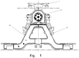
Fig. 1 illustrates a structure diagram of a bogie according to an embodiment of the disclosure; and -
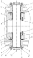
Fig. 2 illustrates a section view A-A of the bogie inFIG. 1 . - Herein, the drawings include the following drawing markers:
10: frame; 11: mounting part; 20: swing bolster; 21: swinging bolster main body; 211: limiting bulge; 212: clamping part; 30: pin shaft; 41: sliding bearing; 42: bearing cover; 43: oil seal member; 44: bush; 45: baffle component; 50: end cover; 51: baffle bulge; 60: observation mirror; 70: antithrust gasket; 80: first sealing ring; 90: second sealing ring; 100: first fastener; 110: second fastener; 120: third fastener; 130: sealant; 140: third sealing ring. - It needs to be noted that embodiments and characteristics of the embodiments of the disclosure may by mutually combined without confliction, and the disclosure is described in details with the drawings and the embodiments.
- An embodiment of the present disclosure provides a bogie. As shown in
Fig. 1 andFig. 2 , the bogie includes aframe 10 and aswing bolster 20, and further includes apin shaft 30, thepin shaft 30 is provided on theframe 10 and theswing bolster 20 in a penetration manner, such that theswing bolster 20 is rotationally provided with respect to theframe 10, theswing bolster 20 includes a swing bolstermain body 21, a bottom end of the swing bolstermain body 21 is used for connecting to a vehicle body, thepin shaft 30 is provided on a top end of the swing bolstermain body 21 in a penetration manner, so as to connect theframe 10 and theswing bolster 20. - According to the bogie of the disclosure, the
frame 10 is rotationally connected with theswing bolster 20 by thepin shaft 30, such that theswing bolster 20 is rotationally provided with respect to theframe 10, the bottom end of the swing bolstermain body 21 of theswing bolster 20 is connected to the vehicle body, then connection of the bogie with the vehicle body is achieved, the vehicle body is stably suspended on a track, and the problem that in the related art a suspended vehicle cannot be operated on a track stably is solved. - As shown in
Fig. 2 , the bogie further includes a sliding bearing 41, the sliding bearing 41 is provided on thepin shaft 30 in a sleeving manner, and theframe 10 is provided on thepin shaft 30 by the sliding bearing 41. Due to adoption of the sliding bearing 41, connection of thepin shaft 30 with theframe 10 is conveniently achieved, and furthermore theswing bolster 20 is rotationally provided with respect to theframe 10. - To achieve positioning of the sliding bearing 41, the bogie further includes a
bearing cover 42, thebearing cover 42 is mounted on theframe 10, and thebearing cover 42 is provided on thepin shaft 30 in a sleeving manner to shield the sliding bearing 41. By mounting thebearing cover 42 on theframe 10, the sliding bearing 41 is fixed in a position of thepin shaft 30. - In addition, the bogie further includes an
oil seal member 43, theoil seal member 43 is provided on an inner side of thebearing cover 42, and theoil seal member 43 is provided on thepin shaft 30 in a sleeving manner. By providing theoil seal 43 on an inner side of thebearing cover 42, an effect of internal oil sealing is achieved. - The bogie further includes a
bush 44, thebush 44 is provided on thepin shaft 30 in a sleeving manner, and thebush 44 is provided in an annular gap between thepin shaft 30 and the swing bolstermain body 21. By providing thebush 44 on thepin shaft 30 in a sleeving manner, thepin shaft 30 is prevented from direct contacting with theframe 10, damage of thepin shaft 30 is reduced, furthermore a function of protecting thepin shaft 30 is achieved, and thepin shaft 30 is enabled to make reciprocation movement in thebush 44. - According to an embodiment of the disclosure, the bogie further includes a
baffle component 45, thebaffle component 45 is provided in the annular gap between thepin shaft 30 and the swing bolstermain body 21, and thebaffle component 45 is provided on both sides of thebush 44. By providing thebaffle component 45, thebush 44 is limited in the gap between thepin shaft 30 and the swing bolstermain body 21. - In an exemplary embodiment, the
baffle component 45 includes two baffle rings, a radial cross section of each of the two baffle ring is of triangle shaped, and the two baffle rings are attached by a respective inclined surface. In an exemplary embodiment, the two baffle rings are connected by the longest side of a respective triangular cross section of the two baffle rings. By adopting the baffle rings with triangular cross sections, elastic positioning of thebush 44 is achieved by mutual extrusion of the two baffle rings, and furthermore the bush is compressed in the annular gap between thepin shaft 30 and the swing bolstermain body 21. - In an exemplary embodiment, the radial cross section of the each of the two baffle ring is of right triangle shaped, and a right angle side of the radial cross section of the each of the two baffle ring is attached to a peripheral surface of the
pin shaft 30. - In the embodiment, as shown in
Fig. 2 , the bogie further includes anend cover 50, theend cover 50 is mounted on the swing bolstermain body 21, and theend cover 50 is provided on a side wall of the swing bolstermain body 21 to shield thepin shaft 30. As theend cover 50 is provided on a side wall of the swing bolstermain body 21, thepin shaft 30 is completely shielded. - In an exemplary embodiment, the
end cover 50 is provided with abaffle bulge 51, alimiting bulge 211 is provided on the swing bolstermain body 21, and thebush 44 and thebaffle component 45 are sandwiched between thebaffle bulge 51 and thelimiting bulge 211. By providing thebaffle bulge 51 and thelimiting bulge 211, positioning of thebush 44 and thebaffle component 45 is conveniently achieved. - As shown in
Fig. 2 , theend cover 50 is provided opposite to an end surface of thepin shaft 30, the bogie further includes anobservation mirror 60, theobservation mirror 60 is mounted on theend cover 50 and is used for observing a positioning state of thepin shaft 30. Before being assembled, a center of an end surface of thepin shaft 30 is marked, a relative position of the marker with respect to theend cover 50 may be observed by theobservation mirror 60, furthermore a positioning state of thepin shaft 30 is observed, and assembling precision of thepin shaft 30 is ensured. - To improving a sealing effect of the
end cover 50 and the swing bolstermain body 21, asealant 130 is sandwiched between theend cover 50 and the swing bolstermain body 21. - To achieve stable connection of the
swing bolster 20 and theframe 10, two oppositely arrangedclamping parts 212 are provided at the top end of the swing bolstermain body 21, theframe 10 is provided with amounting part 11, themounting part 11 is clamped between the twoclamping parts 212, and thepin shaft 30 is provided on the twoclamping parts 212 and the mountingpart 11 in a penetration manner. - In an exemplary embodiment, two
mounting parts 11 are provided, the twomounting parts 11 are provided at an interval between the twoclamping parts 212, that is, themounting parts 11 are sandwiched between the twoclamping parts 212. - To achieve relative rotation of the
frame 10 and theswing bolster 20, the bogie further includes anantithrust gasket 70, theantithrust gasket 70 is positioned in a gap between themounting parts 11 and each of the twoclamping parts 212, and theantithrust gasket 70 is provided around thepin shaft 30. In an exemplary embodiment, theantithrust gasket 70 is fixed on theframe 10 by a first fastener 100. In an exemplary embodiment, theantithrust gasket 70 is made of a wearing-resistant material, and the first fastener 100 is a hexagon socket countersunk head screw. - To further improve sealing between the
mounting part 11 and theclamping part 212, the bogie further includes a first sealing ring 80, at least a part of the first sealing ring 80 is positioned in the gap between themounting parts 11 and theclamping parts 212, and the first sealing ring 80 is provided around theantithrust gasket 70. - Herein, an accommodation groove is formed in an outer circumference wall of the first sealing ring 80, and at least a part of a groove opening of the accommodation groove is positioned in the gap between the mounting
part 11 and the clampingparts 212. In an exemplary embodiment, the first sealing ring 80 is a V-shaped ring. - To prevent invasion of rainwater, the bogie further includes a
second sealing ring 90 which is provided on thebearing cover 42 and athird sealing ring 140 which is provided on the clampingparts 212. In an exemplary embodiment, thesecond sealing ring 90 and thethird sealing ring 140 are O-shaped sealing rings for sealing. - To ensure reliable and safe mounting and connection of different components, the bogie further includes a
second fastener 110 which is provided on thebearing cover 42 and the mountingparts 11 in the penetration manner, and athird fastener 120 which is provided on theend cover 50 and the clampingparts 212 in the penetration manner. In an exemplary embodiment, a part between theend cover 50 and the clampingparts 212 is filled with thesealant 130. - An embodiment of the disclosure further provides a suspended vehicle, and the suspended vehicle includes the above bogie.
- The disclosure relates to a mounting structure of a suspending device. The structure is provided between the swing bolster 20 and the
frame 10. An embodiment of the disclosure sufficiently utilizes spatial structures of theframe 10 and the swing bolster 20, processibility of the mounting structure self is utilized, meanwhile, by using wearing-resistant materials such as the slidingbearing 41 and the antithrust gasket, relative rotation and sliding are achieved. - To achieve reliable compression, a triangular antithrust gasket is adopted to extrude the swing bolster and the
pin shaft 30. In addition, to prevent invasion of rainwater, the O-shaped rings, the V-shaped ring, the sealant, and the like, are adopted for sealing. In order to ensure centering effect of thepin shaft 30, mounting situations of thepin shaft 30 is observed by using theobservation mirror 60. Meanwhile, to ensure assembling fastening and reliability, a loctite adhesive-243 or a Nord-Lock anti-loosening "tooth-shaped" gasket is used. - The description shows that the embodiments of the disclosure achieve the following technical effects:
According to the bogie of the disclosure, the frame is rotationally connected with the swing bolster by the pin shaft, then the swing bolster is rotationally provided with respect to the frame, the bottom end of the swing bolster body of the swing bolster is connected with the vehicle body, furthermore connection of the bogie and the vehicle body is achieved, the vehicle body is stably suspended on the track, and the problem that in the related art the suspended vehicle cannot be operated on the track stably is solved. - The above is only the optional embodiment of the disclosure and not intended to limit the scope of protection of the disclosure. For those skilled in the art, the disclosure may have various modifications and variations. Any modifications, equivalent replacements, improvements and the like made within the spirit and principle of the disclosure shall fall within the scope of protection of the disclosure.
Claims (17)
- A bogie, comprising a frame (10) and a swing bolster (20), and further comprising:a pin shaft (30), wherein the pin shaft (30) is provided on the frame (10) and the swing bolster (20) in a penetration manner, such that the swing bolster (20) is rotationally provided with respect to the frame (10);wherein the swing bolster (20) comprises a swing bolster main body (21); a bottom end of the swing bolster main body (21) is used for connecting to a vehicle body; the pin shaft (30) is provided on a top end of the swing bolster main body (21) in a penetration manner, so as to connect the frame (10) and the swing bolster (20).
- The bogie as claimed in claim 1, further comprising:
a bush (44), wherein the bush (44) is provided on the pin shaft (30) in a sleeving manner, and the bush (44) is provided in an annular gap between the pin shaft (30) and the swing bolster main body (21). - The bogie as claimed in claim 2, further comprising:
a baffle component (45), wherein the baffle component (45) is provided in the annular gap between the pin shaft (30) and the swing bolster main body (21), and the baffle component (45) is provided on both sides of the bush (44). - The bogie as claimed in claim 3, wherein the baffle component (45) comprises two baffle rings, a radial cross section of each of the two baffle rings is of triangle shaped, and the two baffle rings are attached by a respective inclined surface.
- The bogie as claimed in claim 4, wherein the radial cross section of the each of the two baffle rings is of right triangle shaped, and a right angle side of the radial cross section of the each of the two baffle rings is attached to a peripheral surface of the pin shaft (30).
- The bogie as claimed in claim 3, further comprising:
an end cover (50), wherein the end cover (50) is mounted on the swing bolster main body (21), and the end cover (50) is provided on a side wall of the swing bolster main body (21) to shield the pin shaft (30). - The bogie as claimed in claim 6, wherein the end cover (50) is provided with a baffle bulge (51), a limiting bulge (211) is provided on the swing bolster main body (21), and the bush (44) and the baffle component (45) are sandwiched between the baffle bulge (51) and the limiting bulge (211).
- The bogie as claimed in claim 6, wherein the end cover (50) is provided opposite to an end surface of the pin shaft (30), the bogie further comprises an observation mirror (60), wherein the observation mirror (60) is mounted on the end cover (50) and is used for observing a positioning state of the pin shaft (30).
- The bogie as claimed in claim 6, wherein a sealant (130) is sandwiched between the end cover (50) and the swing bolster main body(21).
- The bogie as claimed in claim 1, further comprising a sliding bearing (41), wherein the sliding bearing (41) is provided on the pin shaft (30) in a sleeving manner, and the frame (10) is provided on the pin shaft (30) by the sliding bearing (41) in a sleeving manner.
- The bogie as claimed in claim 10, further comprising a bearing cover (42), wherein the bearing cover (42) is mounted on the frame (10), and the bearing cover (42) is provided on the pin shaft (30) in a sleeving manner to shield the sliding bearing (41).
- The bogie as claimed in claim 11, further comprising an oil seal member (43), wherein the oil seal member (43) is provided on an inner side of the bearing cover (42), and the oil seal member (43) is provided on the pin shaft (30) in a sleeving manner.
- The bogie as claimed in claim 1, wherein two oppositely arranged clamping parts (212) are provided at a top end of the swing bolster main body (21), the frame (10) is provided with a mounting part (11), the mounting part (11) is clamped between the two clamping parts (212), and the pin shaft (30) is provided on the two clamping parts (212) and the mounting part (11) in a penetration manner.
- The bogie as claimed in claim 13, further comprising an antithrust gasket(70), wherein the antithrust gasket (70) is positioned in a gap between the mounting part (11) and each of the two clamping parts (212), and the antithrust gasket (70) is provided around the pin shaft (30).
- The bogie as claimed in claim 14, further comprising a first sealing ring (80), wherein at least a part of the first sealing ring (80) is positioned in the gap between the mounting part (11) and the each of the two clamping parts (212), and the first sealing ring (80) is provided around the antithrust gasket (70).
- The bogie as claimed in claim 15, wherein an accommodation groove is formed in an outer circumference wall of the first sealing ring (80), and at least a part of a groove opening of the accommodation groove is positioned in the gap between the mounting part (11) and the clamping parts (212).
- A suspended vehicle, comprising a bogie, wherein the bogie is the bogie as claimed in any one of claims 1-16.
Applications Claiming Priority (4)
| Application Number | Priority Date | Filing Date | Title |
|---|---|---|---|
| CN201710382301.9A CN107284463B (en) | 2017-05-25 | 2017-05-25 | Bogie and suspension vehicle having the same |
| CN201710382049.1A CN107323476B (en) | 2017-05-25 | 2017-05-25 | Bogie and suspension vehicle having the same |
| CN201710377039.9A CN107284462B (en) | 2017-05-25 | 2017-05-25 | Bogie and suspension vehicle having the same |
| PCT/CN2017/108543 WO2018214403A1 (en) | 2017-05-25 | 2017-10-31 | Bogie and suspended vehicle having same |
Publications (3)
| Publication Number | Publication Date |
|---|---|
| EP3527458A1 true EP3527458A1 (en) | 2019-08-21 |
| EP3527458A4 EP3527458A4 (en) | 2020-06-24 |
| EP3527458B1 EP3527458B1 (en) | 2022-08-10 |
Family
ID=64396196
Family Applications (1)
| Application Number | Title | Priority Date | Filing Date |
|---|---|---|---|
| EP17910726.3A Active EP3527458B1 (en) | 2017-05-25 | 2017-10-31 | Bogie and suspended vehicle having same |
Country Status (3)
| Country | Link |
|---|---|
| EP (1) | EP3527458B1 (en) |
| JP (1) | JP6764026B2 (en) |
| WO (1) | WO2018214403A1 (en) |
Family Cites Families (14)
| Publication number | Priority date | Publication date | Assignee | Title |
|---|---|---|---|---|
| US546928A (en) * | 1895-09-24 | langm | ||
| US945750A (en) * | 1909-05-17 | 1910-01-11 | Frank O Butler | Suspension-railway truck. |
| US1944100A (en) * | 1933-08-30 | 1934-01-16 | Peter J Medor | Suspended railway system |
| US3081711A (en) * | 1960-06-27 | 1963-03-19 | Davino Alphonso | Suspended rapid transit constructions |
| US3525306A (en) * | 1967-12-21 | 1970-08-25 | Common Market Trading Corp Ltd | Suspended railway |
| DD110814A1 (en) * | 1974-04-01 | 1975-01-12 | ||
| SU518402A2 (en) * | 1975-01-10 | 1976-06-25 | Брянский Институт Транспортного Машиностроения | Pivot for railway rolling stock |
| US5197390A (en) * | 1992-01-30 | 1993-03-30 | Transyt Canada Inc. | Suspended vehicle with orientation adjustment by horizontally translating the pivot point relative to the vertical axis |
| JP4097750B2 (en) * | 1997-09-24 | 2008-06-11 | 日本ケーブル株式会社 | Backboard lock mechanism of cable chair chair type carrier |
| US7124692B2 (en) * | 2002-10-15 | 2006-10-24 | Sky Train Corporation | Overhead suspended transportation system and method |
| CN104442880B (en) * | 2014-10-15 | 2017-02-22 | 南车株洲电力机车有限公司 | Suspension type monorail train bogie |
| CN104228865B (en) * | 2014-10-15 | 2016-07-06 | 南车株洲电力机车有限公司 | A kind of traction suspension arrangement |
| CN107284463B (en) * | 2017-05-25 | 2019-03-05 | 中车青岛四方机车车辆股份有限公司 | Bogie and suspension vehicle having the same |
| CN107284462B (en) * | 2017-05-25 | 2019-08-27 | 中车青岛四方机车车辆股份有限公司 | Bogie and suspension vehicle having the same |
-
2017
- 2017-10-31 EP EP17910726.3A patent/EP3527458B1/en active Active
- 2017-10-31 WO PCT/CN2017/108543 patent/WO2018214403A1/en not_active Ceased
- 2017-10-31 JP JP2019522356A patent/JP6764026B2/en active Active
Also Published As
| Publication number | Publication date |
|---|---|
| EP3527458B1 (en) | 2022-08-10 |
| JP6764026B2 (en) | 2020-09-30 |
| JP2019532869A (en) | 2019-11-14 |
| WO2018214403A1 (en) | 2018-11-29 |
| EP3527458A4 (en) | 2020-06-24 |
Similar Documents
| Publication | Publication Date | Title |
|---|---|---|
| RU138198U1 (en) | SEALED SPHERICAL HINGE | |
| US9850940B2 (en) | Dust cover for ball joint | |
| CN107284462B (en) | Bogie and suspension vehicle having the same | |
| EP3527458B1 (en) | Bogie and suspended vehicle having same | |
| CN205446714U (en) | Many lips oil blanket | |
| CN102454972B (en) | Aid-to-navigation lamp sealing structure | |
| CN105041063A (en) | Cam lock and rail vehicle with cam lock | |
| CN203604657U (en) | Box type oil seal with blocking disc | |
| CN107284463B (en) | Bogie and suspension vehicle having the same | |
| CN107323476B (en) | Bogie and suspension vehicle having the same | |
| CN203348357U (en) | Universal transmission shaft angle shaft assembly for special vehicle | |
| CN110159628A (en) | A kind of self-adaptive protector of shield tunnel screwed joint | |
| CN206954239U (en) | Bogie and there is its suspension car | |
| CN204354762U (en) | Balance suspension assembly of off-highway transport vehicle | |
| CN206537347U (en) | Swing arm ball pin assembly and automobile steering system | |
| CN202209423U (en) | Wheel edge oil seal | |
| CN208479778U (en) | The waterproof construction of Tunnel testing camera | |
| CN207034185U (en) | A kind of Brake for vehicle dust cover | |
| CN217107839U (en) | Hub unit | |
| CN212225407U (en) | Novel engine crankcase assembly | |
| CN207034171U (en) | A kind of automobile-used square rubber sealing ring | |
| CN2900733Y (en) | Ground spring seal structure | |
| CN210454316U (en) | Sealing device for mine car wheel | |
| CN204586349U (en) | A kind of castor link span | |
| CN214660537U (en) | Sealing gasket for engine |
Legal Events
| Date | Code | Title | Description |
|---|---|---|---|
| STAA | Information on the status of an ep patent application or granted ep patent |
Free format text: STATUS: THE INTERNATIONAL PUBLICATION HAS BEEN MADE |
|
| PUAI | Public reference made under article 153(3) epc to a published international application that has entered the european phase |
Free format text: ORIGINAL CODE: 0009012 |
|
| STAA | Information on the status of an ep patent application or granted ep patent |
Free format text: STATUS: REQUEST FOR EXAMINATION WAS MADE |
|
| 17P | Request for examination filed |
Effective date: 20190513 |
|
| AK | Designated contracting states |
Kind code of ref document: A1 Designated state(s): AL AT BE BG CH CY CZ DE DK EE ES FI FR GB GR HR HU IE IS IT LI LT LU LV MC MK MT NL NO PL PT RO RS SE SI SK SM TR |
|
| AX | Request for extension of the european patent |
Extension state: BA ME |
|
| REG | Reference to a national code |
Ref country code: DE Ref legal event code: R079 Ref document number: 602017060628 Country of ref document: DE Free format text: PREVIOUS MAIN CLASS: B61F0005040000 Ipc: B61B0003000000 |
|
| A4 | Supplementary search report drawn up and despatched |
Effective date: 20200528 |
|
| RIC1 | Information provided on ipc code assigned before grant |
Ipc: B61F 5/16 20060101ALI20200520BHEP Ipc: B61B 3/00 20060101AFI20200520BHEP Ipc: B61F 5/04 20060101ALI20200520BHEP |
|
| DAV | Request for validation of the european patent (deleted) | ||
| DAX | Request for extension of the european patent (deleted) | ||
| GRAP | Despatch of communication of intention to grant a patent |
Free format text: ORIGINAL CODE: EPIDOSNIGR1 |
|
| STAA | Information on the status of an ep patent application or granted ep patent |
Free format text: STATUS: GRANT OF PATENT IS INTENDED |
|
| INTG | Intention to grant announced |
Effective date: 20220516 |
|
| GRAS | Grant fee paid |
Free format text: ORIGINAL CODE: EPIDOSNIGR3 |
|
| GRAA | (expected) grant |
Free format text: ORIGINAL CODE: 0009210 |
|
| STAA | Information on the status of an ep patent application or granted ep patent |
Free format text: STATUS: THE PATENT HAS BEEN GRANTED |
|
| AK | Designated contracting states |
Kind code of ref document: B1 Designated state(s): AL AT BE BG CH CY CZ DE DK EE ES FI FR GB GR HR HU IE IS IT LI LT LU LV MC MK MT NL NO PL PT RO RS SE SI SK SM TR |
|
| REG | Reference to a national code |
Ref country code: AT Ref legal event code: REF Ref document number: 1510332 Country of ref document: AT Kind code of ref document: T Effective date: 20220815 Ref country code: CH Ref legal event code: EP |
|
| REG | Reference to a national code |
Ref country code: IE Ref legal event code: FG4D |
|
| REG | Reference to a national code |
Ref country code: DE Ref legal event code: R096 Ref document number: 602017060628 Country of ref document: DE |
|
| REG | Reference to a national code |
Ref country code: NL Ref legal event code: MP Effective date: 20220810 |
|
| REG | Reference to a national code |
Ref country code: LT Ref legal event code: MG9D |
|
| PG25 | Lapsed in a contracting state [announced via postgrant information from national office to epo] |
Ref country code: SE Free format text: LAPSE BECAUSE OF FAILURE TO SUBMIT A TRANSLATION OF THE DESCRIPTION OR TO PAY THE FEE WITHIN THE PRESCRIBED TIME-LIMIT Effective date: 20220810 Ref country code: RS Free format text: LAPSE BECAUSE OF FAILURE TO SUBMIT A TRANSLATION OF THE DESCRIPTION OR TO PAY THE FEE WITHIN THE PRESCRIBED TIME-LIMIT Effective date: 20220810 Ref country code: PT Free format text: LAPSE BECAUSE OF FAILURE TO SUBMIT A TRANSLATION OF THE DESCRIPTION OR TO PAY THE FEE WITHIN THE PRESCRIBED TIME-LIMIT Effective date: 20221212 Ref country code: NO Free format text: LAPSE BECAUSE OF FAILURE TO SUBMIT A TRANSLATION OF THE DESCRIPTION OR TO PAY THE FEE WITHIN THE PRESCRIBED TIME-LIMIT Effective date: 20221110 Ref country code: NL Free format text: LAPSE BECAUSE OF FAILURE TO SUBMIT A TRANSLATION OF THE DESCRIPTION OR TO PAY THE FEE WITHIN THE PRESCRIBED TIME-LIMIT Effective date: 20220810 Ref country code: LV Free format text: LAPSE BECAUSE OF FAILURE TO SUBMIT A TRANSLATION OF THE DESCRIPTION OR TO PAY THE FEE WITHIN THE PRESCRIBED TIME-LIMIT Effective date: 20220810 Ref country code: LT Free format text: LAPSE BECAUSE OF FAILURE TO SUBMIT A TRANSLATION OF THE DESCRIPTION OR TO PAY THE FEE WITHIN THE PRESCRIBED TIME-LIMIT Effective date: 20220810 Ref country code: FI Free format text: LAPSE BECAUSE OF FAILURE TO SUBMIT A TRANSLATION OF THE DESCRIPTION OR TO PAY THE FEE WITHIN THE PRESCRIBED TIME-LIMIT Effective date: 20220810 |
|
| REG | Reference to a national code |
Ref country code: AT Ref legal event code: MK05 Ref document number: 1510332 Country of ref document: AT Kind code of ref document: T Effective date: 20220810 |
|
| PG25 | Lapsed in a contracting state [announced via postgrant information from national office to epo] |
Ref country code: PL Free format text: LAPSE BECAUSE OF FAILURE TO SUBMIT A TRANSLATION OF THE DESCRIPTION OR TO PAY THE FEE WITHIN THE PRESCRIBED TIME-LIMIT Effective date: 20220810 Ref country code: IS Free format text: LAPSE BECAUSE OF FAILURE TO SUBMIT A TRANSLATION OF THE DESCRIPTION OR TO PAY THE FEE WITHIN THE PRESCRIBED TIME-LIMIT Effective date: 20221210 Ref country code: HR Free format text: LAPSE BECAUSE OF FAILURE TO SUBMIT A TRANSLATION OF THE DESCRIPTION OR TO PAY THE FEE WITHIN THE PRESCRIBED TIME-LIMIT Effective date: 20220810 Ref country code: GR Free format text: LAPSE BECAUSE OF FAILURE TO SUBMIT A TRANSLATION OF THE DESCRIPTION OR TO PAY THE FEE WITHIN THE PRESCRIBED TIME-LIMIT Effective date: 20221111 |
|
| PG25 | Lapsed in a contracting state [announced via postgrant information from national office to epo] |
Ref country code: SM Free format text: LAPSE BECAUSE OF FAILURE TO SUBMIT A TRANSLATION OF THE DESCRIPTION OR TO PAY THE FEE WITHIN THE PRESCRIBED TIME-LIMIT Effective date: 20220810 Ref country code: RO Free format text: LAPSE BECAUSE OF FAILURE TO SUBMIT A TRANSLATION OF THE DESCRIPTION OR TO PAY THE FEE WITHIN THE PRESCRIBED TIME-LIMIT Effective date: 20220810 Ref country code: ES Free format text: LAPSE BECAUSE OF FAILURE TO SUBMIT A TRANSLATION OF THE DESCRIPTION OR TO PAY THE FEE WITHIN THE PRESCRIBED TIME-LIMIT Effective date: 20220810 Ref country code: DK Free format text: LAPSE BECAUSE OF FAILURE TO SUBMIT A TRANSLATION OF THE DESCRIPTION OR TO PAY THE FEE WITHIN THE PRESCRIBED TIME-LIMIT Effective date: 20220810 Ref country code: CZ Free format text: LAPSE BECAUSE OF FAILURE TO SUBMIT A TRANSLATION OF THE DESCRIPTION OR TO PAY THE FEE WITHIN THE PRESCRIBED TIME-LIMIT Effective date: 20220810 Ref country code: AT Free format text: LAPSE BECAUSE OF FAILURE TO SUBMIT A TRANSLATION OF THE DESCRIPTION OR TO PAY THE FEE WITHIN THE PRESCRIBED TIME-LIMIT Effective date: 20220810 |
|
| REG | Reference to a national code |
Ref country code: DE Ref legal event code: R097 Ref document number: 602017060628 Country of ref document: DE |
|
| PG25 | Lapsed in a contracting state [announced via postgrant information from national office to epo] |
Ref country code: SK Free format text: LAPSE BECAUSE OF FAILURE TO SUBMIT A TRANSLATION OF THE DESCRIPTION OR TO PAY THE FEE WITHIN THE PRESCRIBED TIME-LIMIT Effective date: 20220810 Ref country code: MC Free format text: LAPSE BECAUSE OF FAILURE TO SUBMIT A TRANSLATION OF THE DESCRIPTION OR TO PAY THE FEE WITHIN THE PRESCRIBED TIME-LIMIT Effective date: 20220810 Ref country code: EE Free format text: LAPSE BECAUSE OF FAILURE TO SUBMIT A TRANSLATION OF THE DESCRIPTION OR TO PAY THE FEE WITHIN THE PRESCRIBED TIME-LIMIT Effective date: 20220810 |
|
| REG | Reference to a national code |
Ref country code: CH Ref legal event code: PL |
|
| PLBE | No opposition filed within time limit |
Free format text: ORIGINAL CODE: 0009261 |
|
| STAA | Information on the status of an ep patent application or granted ep patent |
Free format text: STATUS: NO OPPOSITION FILED WITHIN TIME LIMIT |
|
| REG | Reference to a national code |
Ref country code: BE Ref legal event code: MM Effective date: 20221031 |
|
| PG25 | Lapsed in a contracting state [announced via postgrant information from national office to epo] |
Ref country code: AL Free format text: LAPSE BECAUSE OF FAILURE TO SUBMIT A TRANSLATION OF THE DESCRIPTION OR TO PAY THE FEE WITHIN THE PRESCRIBED TIME-LIMIT Effective date: 20220810 Ref country code: LU Free format text: LAPSE BECAUSE OF NON-PAYMENT OF DUE FEES Effective date: 20221031 |
|
| 26N | No opposition filed |
Effective date: 20230511 |
|
| PG25 | Lapsed in a contracting state [announced via postgrant information from national office to epo] |
Ref country code: LI Free format text: LAPSE BECAUSE OF NON-PAYMENT OF DUE FEES Effective date: 20221031 Ref country code: FR Free format text: LAPSE BECAUSE OF NON-PAYMENT OF DUE FEES Effective date: 20221031 Ref country code: CH Free format text: LAPSE BECAUSE OF NON-PAYMENT OF DUE FEES Effective date: 20221031 |
|
| PG25 | Lapsed in a contracting state [announced via postgrant information from national office to epo] |
Ref country code: SI Free format text: LAPSE BECAUSE OF FAILURE TO SUBMIT A TRANSLATION OF THE DESCRIPTION OR TO PAY THE FEE WITHIN THE PRESCRIBED TIME-LIMIT Effective date: 20220810 |
|
| PG25 | Lapsed in a contracting state [announced via postgrant information from national office to epo] |
Ref country code: BE Free format text: LAPSE BECAUSE OF NON-PAYMENT OF DUE FEES Effective date: 20221031 |
|
| PG25 | Lapsed in a contracting state [announced via postgrant information from national office to epo] |
Ref country code: IE Free format text: LAPSE BECAUSE OF NON-PAYMENT OF DUE FEES Effective date: 20221031 |
|
| PG25 | Lapsed in a contracting state [announced via postgrant information from national office to epo] |
Ref country code: HU Free format text: LAPSE BECAUSE OF FAILURE TO SUBMIT A TRANSLATION OF THE DESCRIPTION OR TO PAY THE FEE WITHIN THE PRESCRIBED TIME-LIMIT; INVALID AB INITIO Effective date: 20171031 |
|
| PG25 | Lapsed in a contracting state [announced via postgrant information from national office to epo] |
Ref country code: CY Free format text: LAPSE BECAUSE OF FAILURE TO SUBMIT A TRANSLATION OF THE DESCRIPTION OR TO PAY THE FEE WITHIN THE PRESCRIBED TIME-LIMIT Effective date: 20220810 |
|
| PG25 | Lapsed in a contracting state [announced via postgrant information from national office to epo] |
Ref country code: MK Free format text: LAPSE BECAUSE OF FAILURE TO SUBMIT A TRANSLATION OF THE DESCRIPTION OR TO PAY THE FEE WITHIN THE PRESCRIBED TIME-LIMIT Effective date: 20220810 Ref country code: IT Free format text: LAPSE BECAUSE OF FAILURE TO SUBMIT A TRANSLATION OF THE DESCRIPTION OR TO PAY THE FEE WITHIN THE PRESCRIBED TIME-LIMIT Effective date: 20220810 |
|
| PG25 | Lapsed in a contracting state [announced via postgrant information from national office to epo] |
Ref country code: BG Free format text: LAPSE BECAUSE OF FAILURE TO SUBMIT A TRANSLATION OF THE DESCRIPTION OR TO PAY THE FEE WITHIN THE PRESCRIBED TIME-LIMIT Effective date: 20220810 |
|
| PG25 | Lapsed in a contracting state [announced via postgrant information from national office to epo] |
Ref country code: MT Free format text: LAPSE BECAUSE OF FAILURE TO SUBMIT A TRANSLATION OF THE DESCRIPTION OR TO PAY THE FEE WITHIN THE PRESCRIBED TIME-LIMIT Effective date: 20220810 |
|
| PGFP | Annual fee paid to national office [announced via postgrant information from national office to epo] |
Ref country code: GB Payment date: 20250825 Year of fee payment: 9 |
|
| PG25 | Lapsed in a contracting state [announced via postgrant information from national office to epo] |
Ref country code: TR Free format text: LAPSE BECAUSE OF FAILURE TO SUBMIT A TRANSLATION OF THE DESCRIPTION OR TO PAY THE FEE WITHIN THE PRESCRIBED TIME-LIMIT Effective date: 20220810 |
|
| PGFP | Annual fee paid to national office [announced via postgrant information from national office to epo] |
Ref country code: DE Payment date: 20251020 Year of fee payment: 9 |