EP3527433B1 - Kraftfahrzeug - Google Patents
Kraftfahrzeug Download PDFInfo
- Publication number
- EP3527433B1 EP3527433B1 EP19151574.1A EP19151574A EP3527433B1 EP 3527433 B1 EP3527433 B1 EP 3527433B1 EP 19151574 A EP19151574 A EP 19151574A EP 3527433 B1 EP3527433 B1 EP 3527433B1
- Authority
- EP
- European Patent Office
- Prior art keywords
- component
- motor vehicle
- fastening point
- vehicle according
- screw
- Prior art date
- Legal status (The legal status is an assumption and is not a legal conclusion. Google has not performed a legal analysis and makes no representation as to the accuracy of the status listed.)
- Active
Links
Images



Classifications
-
- B—PERFORMING OPERATIONS; TRANSPORTING
- B60—VEHICLES IN GENERAL
- B60R—VEHICLES, VEHICLE FITTINGS, OR VEHICLE PARTS, NOT OTHERWISE PROVIDED FOR
- B60R13/00—Elements for body-finishing, identifying, or decorating; Arrangements or adaptations for advertising purposes
- B60R13/02—Internal Trim mouldings ; Internal Ledges; Wall liners for passenger compartments; Roof liners
-
- B—PERFORMING OPERATIONS; TRANSPORTING
- B60—VEHICLES IN GENERAL
- B60J—WINDOWS, WINDSCREENS, NON-FIXED ROOFS, DOORS, OR SIMILAR DEVICES FOR VEHICLES; REMOVABLE EXTERNAL PROTECTIVE COVERINGS SPECIALLY ADAPTED FOR VEHICLES
- B60J7/00—Non-fixed roofs; Roofs with movable panels, e.g. rotary sunroofs
- B60J7/20—Vehicle storage compartments for roof parts or for collapsible flexible tops
- B60J7/202—Vehicle storage compartments for roof parts or for collapsible flexible tops being characterised by moveable cover parts for closing the gap between boot lid and rearmost seats
-
- B—PERFORMING OPERATIONS; TRANSPORTING
- B62—LAND VEHICLES FOR TRAVELLING OTHERWISE THAN ON RAILS
- B62D—MOTOR VEHICLES; TRAILERS
- B62D25/00—Superstructure or monocoque structure sub-units; Parts or details thereof not otherwise provided for
- B62D25/08—Front or rear portions
- B62D25/10—Bonnets or lids, e.g. for trucks, tractors, busses, work vehicles
- B62D25/105—Bonnets or lids, e.g. for trucks, tractors, busses, work vehicles for motor cars
Definitions
- the invention relates to a motor vehicle according to the preamble of claim 1.
- the invention relates to the fastening of decorative components or panels or the like, which have at least one externally visible outer surface. If such a cover is screwed to another body component with a surface that is visible to the outside, the screw connection must be carried out with a defined screwing torque.
- a defined screwing torque ensures that the outer surface of the panel does not warp or that the outer surface of the panel remains unchanged and / or that increased gap formations are avoided or that the gap joints are uniform.
- the screw connection at the fastening point is designed as a block, i.e. the two components to be connected lie against each other and are pressed against each other during the screwing process.
- a desired component contact does not necessarily result on the edges of the components to be connected that are spaced apart from the screw connection point. Increased play must be provided so that no tension is brought into the component due to the (block) screw connection.
- the object of the invention is to create a motor vehicle in which a trim strip that bridges and / or covers the overlapping edges of two adjacent components can be fastened without any visible deformation.
- a motor vehicle according to the invention has two components.
- the two components according to the invention are an assembly part and a body component of a convertible top compartment cover of a motor vehicle designed as a convertible.
- the two components overlap at their edges.
- the two edges are covered by a decorative strip or panel.
- the overlap takes place in that the edges of the decorative strip rest on the edges of the respective component.
- a predetermined number of fastening points for a screw connection is formed on the panel over the course of the two components to be covered.
- the decorative strip advantageously has a carrier component and a decorative component attached to it.
- the fastening points are formed in the carrier component.
- Two opposing slots are formed at a distance from the respective fastening point.
- the two opposite slots at the respective fastening point are advantageously designed in such a way that there is elastic deformation at the respective fastening point during the screw connection, so that the elasticity at the respective fastening point introduces structural pretension into the respective fastening point.
- a head of a screw rests on the respective fastening point on the carrier component of the decorative strip.
- a threaded bolt section of the respective screw is passed through a through opening formed in the support component and through a through opening formed in the edge of the one component opposite to the support component.
- the respective screw is fastened to an outer surface of an edge of the one component via a respective nut.
- the carrier component and thus the decorative strip are advantageously fastened to the one component by fastening the respective screw to the component.
- a side edge of the decorative component rests on one component and an opposite side edge of the decorative strip rests on the edge of the other component.
- the stiffness and thus the elastic deformability of the section of the carrier component lying between the slots can be adjusted over the length of the slots and / or the width of the slots.
- the respective fastening point is pot-shaped with circumferential side walls and a base that is integrally connected to the circumferential side walls.
- the rigidity and thus the elastic deformability of the respective fastening point is advantageously adjustable by a corresponding design of the shape and / or the thickness of the circumferential side wall and / or the shape and / or the thickness of the bottom of the respective fastening point.
- a recess is formed between the two edges, the recess being covered by the decorative strip or panel.
- the Figure 1 shows a rear area 2 of a motor vehicle 1 in which a roof 3 is formed by a top 4.
- the convertible top 4 is located in the Figure 1 in one closed state 5a.
- a front end 2a of a side panel 2b located in a vehicle interior 8 is visible.
- a U-shaped body component 11 of a convertible top compartment cover 7 is visible.
- the cover or trim 10 shown is covered by the lower end 9 of the top 4.
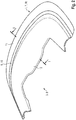
- the Figure 2 shows a convertible top compartment lid 7 in an open state 5b of a convertible top compartment 15 ( Figure 3 ) located convertible top 4.
- a cavity 15a of the convertible top compartment 15 is formed below the convertible top compartment cover 7.
- the convertible top compartment lid 7 consists essentially of the U-shaped body component 11 and an assembly part 12 mounted thereon.
- the body component 11 and the assembly part 12 overlap in an overlap area 6 the mounting part 12 is in the Figure 2 Decorative strip 10 shown attached.
- FIG. 11 shows a sectional view according to the sectional views II in FIG Figures 1 and 2 .
- the mounting part 12 is only partially shown.
- An edge 13 of the mounting part 12 facing the decorative strip 10 rests in the overlap region 6 on an upper, lowered edge section 14 of the body component 11 facing the mounting part 12.
- the mounting part 12 is attached to the body component 11 in a known manner.
- the upper, lowered edge section 14 of the body component 11 is adjoined by an (outer) section 18 of the body component 11 raised by a circumferential step 16.
- the raised (outer) section 18 of the body component 11 has an outer body surface 17.
- the upper edge section 14 of the body component 11 extends into an (outer) section 18 of the body component 11 over.
- the (outer) section 18 of the body component 11 has an outer body surface 17.
- a circle 19 is shown below the section 18 of the body component 11 at a right end 11a of the body component 11, which symbolically represents the hinges arranged on the body component 11 and a resulting axis of rotation 20.
- An arrow P 7 indicates a pivoting direction of the convertible top compartment lid 7 about the axis of rotation 20.
- the movement of the convertible top compartment cover 7 takes place in another known form.
- a recess 21 running between the edge 13 of the mounting part 12 and the circumferential step 16 of the body component 11 in the vehicle longitudinal direction x is covered by the decorative strip 10.
- the trim 10 has a in the Figure 4 The support component 22 shown and a decorative component 23 attached thereto.
- the decorative component 23 has, inter alia, an optical function.
- the fastening of the decorative component 23 to the carrier component 22 of the decorative strip 10 can take place in a form-fitting manner, for example by means of a clip connection 24 and / or materially via an adhesive connection 25.
- the decorative component 23 of the decorative strip 10 has two opposing, circumferential side edges 26, 27.
- the side edge 26 rests on a stepped section 28 of the edge 13 of the mounting part 12.
- the opposite side edge 27 has an approximately U-shaped cross section.
- a free end 29 of the side edge 27 rests on an outwardly pointing outer surface 30 of the edge 14 of the body component 11.
- a circumferential sealing strip 31 for example a rubber piping, is arranged on the outer surface 30 of the painted edge 14 of the body component 11 or there are point-shaped elevations 32, for example made of rubber, formed on the outer surface 30 of the edge 14 of the body component.
- the carrier component 22 rests with its side edge 33 facing the mounting part 12 on a further stepped section 34 of the edge 13 of the mounting part 12.
- An opposite side edge 35 of the carrier component 22 is in the embodiment shown with a circumferential projection extending downward in the vertical direction z or a protruding portion 36 or a longitudinal web 55 corresponding to FIG Figure 4 Mistake.
- a free end 37 of the protruding section 36 of the side edge 35 of the carrier component is spaced from the outer surface 30 of the edge 14 of the body component 11 by a defined distance a.
- a recessed support section 38 for a head 39 of a screw 40 is formed approximately in the middle. Furthermore, a through opening 41 is formed in the support section 38 for the passage of the bolt section 42 provided with a thread.
- the recessed support section 38 is spaced from adjacent sections 43, 44 of the support component 22 by a gap or slot 45, 46 in each case.
- a through opening 48, 49 is formed in the upper edge section 14 of the body component 11 and in a lower edge section 47 attached to it for the threaded bolt section 42 of the screw 40 to pass through.
- the threaded bolt section 42 of the screw 40 shown protrudes beyond the through opening 49 of the lower edge section 47 of the body component 11 by a predetermined distance b.
- a free end 50 of the threaded bolt section 42 of the screw 40 is fastened via a nut 51 to a downwardly pointing outer surface 52 of the lower edge section 47 of the body component 11.
- the respective screw 40 is arranged in the respective through opening 41 of the recessed support section 38 before the decorative component 23 is fastened to the carrier component 22.
- the fully assembled decorative strip 10 is arranged with the respective protruding free end 50 of the threaded bolt section 42 of the respective screw 40 in the respective through openings 48, 49 of the upper edge section 14 or the lower edge section 47.
- the respective screw 40 is then screwed to the outer surface 52 of the lower edge section 47 via a nut 51 in each case.
- a vertical arrow F 11, 23 shows the force exerted by the carrier component 22 via the clip connection 24 and / or via the adhesive connection 25 on the side edge 27 of the decorative component 23 of the decorative strip 10.
- the side edge 27 of the decorative component 23 of the decorative strip 10 presses over the support surface 31, 32 on the upper section 14 of the body component 11. As a result, the side edge 27 of the decorative component 23 rests on the upper section 14 of the body component 11.
- a second resilient connection results from the fact that the support section 38 is resilient or more flexible due to elastic deformation via the longitudinal gaps or longitudinal slots 45, 46 in the carrier component 22.
- the respective two opposite slots 45, 46 at the respective fastening point 38, 41, 53 are designed such that elastic deformation is present at the respective fastening point 38, 41, 53 during the screw connection. Due to the elasticity at the respective fastening point 38, 41, 53, a structural pretension is introduced into the respective fastening point 38, 41, 53.
- the rigidity and thus the elastic deformability of the section 22a of the carrier component 22 lying between the slots 45, 46 can be adjusted.
- the screwing points are usually screwed to a block.
- the contact force at the edge areas (contact points) cannot be influenced by the tightening torque.
- the two longitudinal slots or the two opposing slots 45, 46 laterally next to the respective screw connection 39, 40, 51 allow elastic deformation in this area of section 22a. Due to the elasticity of the section 22a, a structural prestress can be introduced between the carrier component 22 and the component 11. This compensates for the tolerances. This bias acts on the support points of the decorative component 23 on the opposite edges 26, 27 of the decorative component 23 on the one hand on the component 11 and on the other hand on the component 12.
- the force distribution can be applied to bearing points (edges) of the decorative member 23 on the opposite edges 26, 27 of the ornamental member 23 on the one hand on the component 11 and on the other hand on the component 12 can be influenced and controlled.
- the above-mentioned bias force distribution, and the maximum force can be obtained by design change, the width and the length b 45,46 45,46 I of the longitudinal slits 45 are changed, 46th
- the amount required to turn the nut 51 increases Torque and the bearing force on the opposite edges 26, 27 of the decorative component 23 on the one hand on the component 11 and on the other hand on the component 12.
- the edge 33 of the carrier component 22 rests against the edge 13 of the mounting part or component 12.
- the tightening torque of the nut 51 thus has no effect on the decorative component 23 of the decorative strip 10, so that there is no tension or distortion of the decorative component 23 of the decorative strip 10.
- the decorative component 23 of the decorative strip 10 rests evenly on the contact points 12, 13, 28 or 11, 31, 32, 14 that form the joints.
- FIG. 4 a fastening point 53 of a nut 51 on a screw 40 on the outer surface 52 of an underside 54 of the lower edge section 47 of the carrier component 22 is shown. Furthermore go from the Figure 4 the two longitudinal gaps 45, 46 on the carrier component 22 of the trim strip 10.
- a reinforcement ramp 58 which is arranged between two transverse ribs 56 spaced apart from one another, adjoins the longitudinal gap 46.
- the underside 54 of the carrier component 22 has longitudinal webs 55a, 55b and 55c.
- the longitudinal webs 55a, 55b, 55c are connected to one another by transverse ribs 56 that are spaced apart from one another in order to stiffen the carrier component 22.
Landscapes
- Engineering & Computer Science (AREA)
- Mechanical Engineering (AREA)
- Vehicle Interior And Exterior Ornaments, Soundproofing, And Insulation (AREA)
- Connection Of Plates (AREA)
Description
- Die Erfindung betrifft ein Kraftfahrzeug gemäß dem Oberbegriff des Anspruchs 1.
- Die Erfindung betrifft die Befestigung von Zierbauteilen oder Blenden oder dergleichen, die zumindest eine außen sichtbare Außenfläche aufweisen. Wenn eine derartige Blende mit einer nach außen sichtbaren Fläche an einem anderen Karosserie-bauteil verschraubt wird, muss die Verschraubung mit einem definierten Anschraubmoment durchgeführt werden.
- Ein definiertes Anschraubmoment stellt sicher, dass sich die Außenfläche der Blende nicht verzieht bzw. dass die Außenfläche der Blende unverändert bleibt und/oder dass erhöhte Spaltbildungen vermieden sind bzw. dass die Spaltfugen gleichmäßig sind.
- Bei einer bekannten Verschraubungsart ist die Verschraubung an der Befestigungsstelle auf Block ausgelegt, d.h. die beiden zu verbindenden Bauteile liegen aneinander und werden beim Schraubvorgang aneinander gepresst. Bei dieser Verschraubungsart ergibt sich nicht zwangsläufig eine gewünschte Bauteilanlage an den zu der Verschraubungsstelle beabstandeten Rändern der zu verbindenden Bauteile. Es muss ein erhöhtes Spiel vorgesehen sein, damit aufgrund der (Block-) Verschraubung keine Verspannung ins Bauteil gebracht wird.
- Aus der
FR 2719271 A1 - Aufgabe der Erfindung ist es, ein Kraftfahrzeug zu schaffen, bei dem eine Zierleiste, die sich überlappende Ränder zweier benachbarter Bauteilen überbrückt und/oder überdeckt, ohne eine sichtbare Verformung befestigbar ist.
- Diese Aufgabe wird durch die Merkmale des Anspruchs 1 gelöst.
- Ein erfindungsgemäßes Kraftfahrzeug weist zwei Bauteile auf. Die beiden erfindungsgemäßen Bauteile sind ein Montageteil und ein Karosserie-Bauteil eines Verdeckkastendeckels eines als Cabriolet ausgebildeten Kraftfahrzeuges. Die beiden Bauteile überlappen sich an ihren Rändern. Die beiden Ränder sind durch eine Zierleiste oder Blende überdeckt. Die Überdeckung erfolgt dadurch, dass die Ränder der Zierleiste an den Rändern des jeweiligen Bauteils aufliegen. Über den Verlauf der beiden zu überdecken- den Bauteilen ist eine vorgegebene Anzahl an Befestigungsstellen für eine Schraubverbindung an der Blende ausgebildet.
- Vorteilhafterweise weist die Zierleiste ein Trägerbauteil und ein daran befestigtes Zierbauteil auf. In dem Trägerbauteil sind die Befestigungsstellen ausgebildet. Beabstandet zu der jeweiligen Befestigungsstelle sind jeweils zwei gegenüberliegende Schlitze ausgebildet.
- Die jeweiligen beiden gegenüberliegenden Schlitze an der jeweiligen Befestigungsstelle sind vorteilhafterweise so ausgelegt, dass eine elastische Verformung an der jeweiligen Befestigungsstelle bei der Verschraubung vorhanden ist, so dass durch die Elastizität an der jeweiligen Befestigungsstelle eine konstruktive Vorspannung in die jeweilige Befestigungsstelle eingebracht ist.
- In einer vorteilhaften Ausführungsform liegt an der jeweiligen Befestigungsstelle an dem Trägerbauteil der Zierleiste ein Kopf einer Schraube auf. Ein mit Gewinde versehener Bolzenabschnittes der jeweiligen Schraube ist durch eine in dem Trägerbauteil ausgebildete Durchgangsöffnung und durch eine Durchgangsöffnung hindurchgeführt, die in dem zu dem Trägerbauteil gegenüberliegenden Rand des einen Bauteils ausgebildet sind. Über jeweils eine Mutter ist die jeweilige Schraube an einer Außenfläche eines Randes des einen Bauteils befestigt.
- Über die Befestigung der jeweiligen Schraube an dem Bauteil ist das Trägerbauteil und damit die Zierleiste vorteilhafterweise an dem einen Bauteil befestigt.
- Im befestigten Zustand des Trägerbauteils und damit der Zierleiste an dem einen Bauteil liegt in einer vorteilhaften Ausführungsform ein Seitenrand des Zierbauteils an dem einen Bauteil auf und ein dazu gegenüberliegender Seitenrand der Zierleiste liegt an dem Rand des anderen Bauteils auf.
- Vorteilhafterweise ist über die Länge der Schlitze und/oder die Breite der Schlitze die Steifigkeit und damit die elastische Verformbarkeit des zwischen den Schlitzen liegenden Abschnittes des Trägerbauteils einstellbar.
- Die jeweilige Befestigungsstelle ist in einer vorteilhaften Ausführungsform topfförmig mit umlaufenden Seitenwänden und einem mit den umlaufenden Seitenwänden einstückig verbundenen Boden ausgebildet.
- Die Steifigkeit und damit die elastische Verformbarkeit der jeweiligen Befestigungsstelle ist vorteilhafterweise durch eine entsprechende Auslegung der Form und/oder der Dicke der umlaufenden Seitenwand und/oder der Form und/oder der Dicke des Bodens der jeweiligen Befestigungsstelle einstellbar.
- In einer vorteilhaften Ausführungsform ist zwischen den beiden Rändern eine Vertiefung ausgebildet, wobei die Vertiefung durch die Zierleiste oder Blende überdeckt ist.
- Eine Ausführungsform der Erfindung wird nachstehend anhand der Zeichnungen beispielshalber beschrieben. Dabei zeigen:
- Figur 1
- eine perspektivische Ansicht eines Heckbereichs eines Kraftfahrzeuges mit einer Verdeckanordnung, wobei sich die Verdeckanordnung im geschlossenen Zustand befindet,
- Figur 2
- eine schematische, perspektivische Ansicht einer Verdeckkastenklappe,
- Figur 3
- eine Schnittansicht längs der Linie I-I in der
Figur 1 jedoch bei einem geöffneten Verdeck, und - Figur 4
- eine perspektivische Ansicht einer teilweise dargestellten Unterseite eines Trägerbauteils einer zu befestigenden Blende, die eine Befestigungsstelle einer Schraubverbindung an einer Außenfläche zeigt.
- Die
Figur 1 zeigt einen Heckbereich 2 eines Kraftfahrzeuges 1 bei dem ein Dach 3 durch ein Verdeck 4 gebildet ist. Das Verdeck 4 befindet sich in derFigur 1 in einem geschlossenen Zustand 5a. Im geschlossenen Zustand 5a des Verdeckes 4 ist in derFigur 1 ein vorderes Ende 2a einer sich in einem Fahrzeuginnenraum 8 befindlichen Seitenverkleidung 2b sichtbar. - An ein unteres Ende 9 des Verdecks 4 schließt sich in den
Figuren 1 und2 sichtbar ein U-förmig ausgebildetes Karosserie-Bauteil 11 eines Verdeckkastendeckels 7 an. Eine in derFigur 2 gezeigte Blende oder Zierleiste 10 wird durch das untere Ende 9 des Verdecks 4 verdeckt. - Die
Figur 2 zeigt einen Verdeckkastendeckel 7 bei einem geöffneten Zustand 5b eines sich in einem Verdeckkasten 15 (Figur 3 ) befindlichen Verdecks 4. Ein Hohlraum 15a des Verdeckkastens 15 ist unterhalb des Verdeckkastendeckels 7 ausgebildet. - Der Verdeckkastendeckel 7 besteht im Wesentlichen aus dem U-förmig ausgebildeten Karosserie-Bauteil 11 und einem daran montierten Montageteil 12. Das Karosserie-Bauteil 11 und das Montageteil 12 überdecken sich in einem Überlappungsbereich 6. In dem Überlappungsbereich 6 zwischen dem Karosserie-Bauteil 11 und dem Montageteil 12 ist die in der
Figur 2 gezeigte Zierleiste 10 angebracht. - Die
Figur 3 zeigt eine Schnittdarstellung gemäß den Schnittansichten I-I in denFiguren 1 und 2 . Das Montageteil 12 ist nur teilweise dargestellt. Ein der Zierleiste 10 zugewandter Rand 13 des Montageteils 12 liegt im Überlappungsbereich 6 auf einem dem Montageteil 12 zugewandten oberen, abgesenkten Randabschnitt 14 des Karosserie-Bauteils 11 auf. Das Montageteil 12 ist an dem Karosserie-Bauteil 11 in bekannter Weise befestigt. - In der gezeigten Ausführungsform schließt sich an den oberen, abgesenkten Randabschnitt 14 des Karosserie-Bauteils 11 ein um eine umlaufende Stufe 16 erhöhter (Außen-) Abschnitt 18 des Karosserie-Bauteils 11 an. Der erhöhte (Außen-) Abschnitt 18 des Karosserie-Bauteils 11 weist eine Karosserieaußenfläche 17 auf.
- In einer nicht gezeigten, anderen Ausführungsform geht der obere Randabschnitt 14 des Karosserie-Bauteils 11 in einen (Außen-) Abschnitt 18 des Karosserie-Bauteils 11 über. Der (Außen-) Abschnitt 18 des Karosserie-Bauteils 11 weist eine Karosserieaußenfläche 17 auf.
- In der gezeigten Ausführungsform ist unterhalb des Abschnittes 18 des Karosserie-Bauteils 11 an einem rechten Ende 11a des Karosserie-Bauteils 11 ein Kreis 19 dargestellt, der symbolisch für am Karosserie-Bauteil 11 angeordnete Scharniere und eine damit sich ergebende Drehachse 20 steht. Ein Pfeil P7 zeigt eine Schwenkrichtung des Verdeckkastendeckels 7 um die Drehachse 20 an.
- In einer nicht gezeigten, anderen Ausführungsform erfolgt die Bewegung des Verdeckkastendeckels 7 in einer anderen bekannten Form.
- Eine zwischen dem Rand 13 des Montageteils 12 und der umlaufenden Stufe 16 des Karosserie-Bauteils 11 in Fahrzeuglängsrichtung x verlaufende Vertiefung 21 ist durch die Zierleiste 10 abgedeckt.
- Die Zierleiste 10 weist ein in der
Figur 4 gezeigtes Trägerbauteil 22 und ein daran befestigtes Zierbauteil 23 auf. Das Zierbauteil 23 hat unter anderem eine optische Funktion hat. Die Befestigung des Zierbauteils 23 an dem Trägerbauteil 22 der Zierleiste 10 kann formschlüssig beispielsweise über eine Clipsverbindung 24 und/oder stoffschlüssig über eine Klebeverbindung 25 erfolgen. - Das Zierbauteil 23 der Zierleiste 10 weist zwei gegenüberliegende, umlaufende Seitenränder 26, 27 auf. In der gezeigten Ausführungsform liegt der Seitenrand 26 an einem abgestuften Abschnitt 28 des Randes 13 der Montageteils 12 auf. Der dazu gegenüberliegende Seitenrand 27 weist in der gezeigten Ausführungsform einen in etwa U-förmigen Querschnitt auf.
- Ein freies Ende 29 des Seitenrandes 27 liegt an einer nach außen zeigenden Außenfläche 30 des Randes 14 des Karosserie-Bauteils 11 auf. Zur definierten Auflage des freien Endes 29 des Zierbauteils 23 der Zierleiste 11 ist an der Außenfläche 30 des lackierten Randes 14 des Karosserie-Bauteils 11 eine umlaufende Dicht-Leiste 31, beispielsweise ein Gummi-Keder, angeordnet oder es sind punktförmige Erhebungen 32, beispielsweise aus Gummi, an der Außenfläche 30 des Randes 14 des Karosserie-Bauteils ausgebildet.
- Das Trägerbauteil 22 liegt mit seinem dem Montageteil 12 zugewandten Seitenrand 33 an einem weiteren abgestuften Abschnitt 34 des Randes 13 des Montageteils 12 auf. Ein dazu gegenüberliegender Seitenrand 35 des Trägerbauteils 22 ist in der gezeigten Ausführungsform mit einem in senkrechter Richtung z nach unten sich erstreckenden umlaufenden Vorsprung oder einem vorstehenden Abschnitt 36 oder einem Längssteg 55 entsprechend der
Figur 4 versehen. - Ein freies Ende 37 des vorstehenden Abschnittes 36 des Seitenrandes 35 des Trägerbauteils ist von der Außenfläche 30 des Randes 14 des Karosserie-Bauteils 11 um einen definierten Abstand a beabstandet.
- In dem Trägerbauteil 22 der Zierleiste 10 ist in etwa mittig ein vertiefter Auflageabschnitt 38 für einen Kopf 39 einer Schraube 40 ausgebildet. Ferner ist in dem Auflageabschnitt 38 eine Durchgangsöffnung 41 zum Hindurchführen des mit einem Gewinde versehenen Bolzenabschnittes 42 ausgebildet. Der vertiefte Auflageabschnitt 38 ist von dazu benachbarten Abschnitten 43, 44 des Trägerbauteils 22 um jeweils einen Spalt oder Schlitz 45, 46 beabstandet.
- Zur Hindurchführung des mit einem Gewinde versehenen Bolzenabschnittes 42 der Schraube 40 ist in dem oberen Randabschnitt 14 des Karosserie-Bauteils 11 und einem daran befestigten, unteren Randabschnitt 47 jeweils eine Durchgangsöffnung 48, 49 ausgebildet.
- In der gezeigten Ausführungsform ragt der mit einem Gewinde versehene Bolzenabschnitt 42 der gezeigten Schraube 40 über die Durchgangsöffnung 49 des unteren Randabschnittes 47 des Karosserie-Bauteils 11 um einen vorbestimmten Abstand b über.
- Ein freies Ende 50 des mit einem Gewinde versehenen Bolzenabschnittes 42 der Schraube 40 ist über eine Mutter 51 an einer nach unten zeigenden Außenfläche 52 des unteren Randabschnittes 47 des Karosserie-Bauteils 11 befestigt.
- In einer Ausführungsform erfolgt die Anordnung der jeweiligen Schraube 40 in der jeweiligen Durchgangsöffnung 41 des vertieften Auflageabschnittes 38 vor der Befestigung des Zierbauteils 23 an dem Trägerbauteil 22.
- Die fertig montierte Zierleiste 10 wird mit dem jeweiligen überstehenden freien Ende 50 des mit einem Gewinde versehenen Bolzenabschnittes 42 der jeweiligen Schraube 40 in den jeweiligen Durchgangsöffnungen 48, 49 des oberen Randabschnittes 14 bzw. des unteren Randabschnittes 47 angeordnet. Nachfolgend wird die jeweilige Schraube 40 über jeweils eine Mutter 51 an der Außenfläche 52 des unteren Randabschnittes 47 verschraubt.
- Wie aus der
Figur 3 hervorgeht, liegt der zum Montageteil 12 zeigende Seitenrand 33 des Trägerbauteils 22 an dem unteren abgestuften Abschnitt 34 des Randes 13 des Montageteils 12 auf, wie dies durch einen senkrechten Pfeil F12,22 gezeigt ist. - Ein senkrechter Pfeil F11, 23 zeigt die Krafteinwirkung vom Trägerbauteil 22 über die Clipsverbindung 24 und/oder über die Klebeverbindung 25 auf den Seitenrand 27 des Zierbauteils 23 der Zierleiste 10. Der Seitenrand 27 des Zierbauteils 23 der Zierleiste 10 drückt über die Auflagefläche 31, 32 auf den oberen Abschnitt 14 des Karosseriebauteils 11. Dadurch liegt der Seitenrand 27 des Zierbauteils 23 auf dem oberen Abschnitt 14 des Karosseriebauteils 11 auf.
- Durch die in der
Figur 3 gezeigte Befestigung ergibt sich eine erste federnde Verbindung zwischen dem Trägerbauteil 22, das auf den Rand 13 des Montageteils 12 über die durch die Verschraubung wirkende Krafteinwirkung F12, 22 drückt, und dem Seitenrand 27 des Zierbauteils 23, der auf die Außenfläche 30 des oberen Randabschnittes 14 des Karosserie-Bauteils 11 über die durch die Verschraubung wirkende Krafteinwirkung F11, 23 drückt. - Eine zweite federnde Verbindung ergibt sich dadurch, dass der Auflageabschnitt 38 über die Längsspalten oder Längsschlitze 45, 46 im Trägerbauteil 22 das Trägerbauteil 22 federnd oder durch elastische Verformung nachgiebiger ist.
- Die jeweiligen beiden gegenüberliegenden Schlitze 45, 46 an der jeweiligen Befestigungsstelle 38, 41, 53 sind so ausgelegt, dass eine elastische Verformung an der jeweiligen Befestigungsstelle 38, 41, 53 bei der Verschraubung vorhanden ist. Durch die Elastizität an der jeweiligen Befestigungsstelle 38, 41, 53 ist eine konstruktive Vorspannung in die jeweilige Befestigungsstelle 38, 41, 53 eingebracht.
- Über die Länge der Schlitze 45, 46 und/oder die Breite der Schlitze 45, 46 ist die Steifigkeit und damit die elastische Verformbarkeit des zwischen den Schlitzen 45, 46 liegenden Abschnittes 22a des Trägerbauteils 22 einstellbar.
- Bei einer bekannten Schraubenverbindung entsteht in den Toleranzlagen der Bauteile 10, 11, 12 entweder ein Spalt oder es entsteht eine hohe Verspannung.
- Durch eine punktuelle Belastung kann bei einer direkten Schraubverbindung eine Kraft auf die Sichtfläche oder Außenfläche 23a des Zierbauteils 23 wirken. Bei einer direkten Schraubverbindung besteht die Gefahr der Bildung von Dellen oder es entstehen Abzeichnungen an der Außenfläche 23a des Zierbauteils 23.
- Ferner ist eine gleichmäßige Anlagekraft über den ganzen Auflagebereich, d.h. an der Dichtung 31 und an den Auflagestellen zwischen dem Zierbauteil 23 und den Bauteilen 11,12 erforderlich.
- Bei einer bekannten Schraubenverbindung ohne Toleranzausgleich werden die Bauteile punktuell stark belastet. Dies führt in Zusammenwirkung mit einer Dichtung zur Durchbiegung/Wellenbildung an der Zierleiste 10 bzw. dem Zierbauteil 23. In der Folge bewirkt die punktuelle Belastung eine ungleichmäßige Anlagekraft an der Dichtung 31. Die Dichtung 31 kann nicht sicher Abdichten. Zur Behebung dieser Probleme muss die Anlagekraft und die Kraftverteilung ggf. an die Anbausituation konstruktiv angepasst werden.
- Bei einer bekannten Schraubenverbindung wird meist an den Anschraubpunkten auf Block verschraubt. Die Anlagekraft an den Randbereichen (Auflagestellen) kann mit dem Anzugsmoment nicht beeinflusst werden.
- Durch die beiden Längsschlitze bzw. die beiden gegenüberliegenden Schlitze 45, 46 seitlich neben der jeweiligen Schraubverbindung 39, 40, 51 wird in diesem Bereich des Abschnittes 22a eine elastische Verformung zugelassen. Aufgrund der Elastizität des Abschnittes 22a kann eine konstruktive Vorspannung zwischen dem Trägerbauteil 22 und dem Bauteil 11 eingebracht werden. Dadurch werden die Toleranzen ausgeglichen. Diese Vorspannung wirkt auf die Auflagestellen des Zierbauteils 23 an den gegenüberliegenden Rändern 26, 27 des Zierbauteils 23 zum einen auf das Bauteil 11 und zum anderen auf das Bauteil 12.
- Durch die Längsschlitze 45, 46 wird die beim Verschrauben entstehende Kraft nicht direkt an der Schraubstelle 40, 51 in das Trägerbauteil 22 eingeleitet, sondern die beim Verschrauben entstehende Kraft wird seitlich an den beiden gegenüberliegenden Enden des Abschnittes 22a in Höhe der Enden 45a, 45b und 46a und 46b der Längsschlitze 45, 46 eingeleitet. Durch die Kraftverteilung wird die Kraft auf den Auflagestellen (Randbereiche) des Zierbauteils 23 an den gegenüberliegenden Rändern 26, 27 des Zierbauteils 23 zum einen auf das Bauteil 11 und zum anderen auf das Bauteil 12 gleichmäßig verteilt. Dadurch wird auch eine gleichmäßige Anlagekraft an der Dichtung 31 erzielt.
- Durch die Gestaltung der Längsschlitze 45, 46, d.h. die Breite b 45,46 und die Länge I45,46 der Längsschlitze 45, 46 kann die Kraftverteilung an den Auflagestellen (Randbereichen) des Zierbauteils 23 an den gegenüberliegenden Rändern 26, 27 des Zierbauteils 23 zum einen auf das Bauteil 11 und zum anderen auf das Bauteil 12 beeinflusst und gesteuert werden. Die obengenannte Vorspannung, die Kraftverteilung, und die maximale Kraft kann durch konstruktive Anpassung die Breite b45,46 und die Länge I45,46 der Längsschlitze 45, 46 verändert werden.
- Bei dem Verdrehen der jeweiligen Mutter 51 wird die dazugehörige Schraube 40 und damit das Trägerbauteil 22 durch die elastische Verformung des Abschnittes 22a an der Befestigungsstelle 38 um einen Freiraum oder Abstand 57 nach unten gezogen, bis das Trägerbauteil 22 in Anlage an dem Karosserie-Bauteil 11 kommt.
- Nach der Anlage des Trägerbauteils 22 an dem Karosserie-Bauteil 11 und einem weiteren Drehen der jeweiligen Mutter 51 steigen das zum Drehen der Mutter 51 erforderliche Drehmoment und die Auflagekraft an den gegenüberliegenden Rändern 26, 27 des Zierbauteils 23 zum einen auf das Bauteil 11 und zum anderen auf das Bauteil 12 an. Unterhalb des Randes 26 des Zierbauteils 23 liegt der Rand 33 des Trägerbauteils 22 an dem Rand 13 des Montageteils oder Bauteils 12 an. Dadurch kann die auf den Rand 26 des Zierbauteils 23 wirkende Kraft nicht so stark ansteigen wie auf den Rand 27 des Zierbauteils 23 auf das Karosserie-Bauteil 11.
- Durch das Anziehen der jeweiligen Mutter 51 wird über die Lastverteilung an den Enden des Abschnittes 22a ein eventuell vorhandenes Spiel zwischen den Seitenrändern 26, 27 des Zierbauteils 23 und den dazu gegenüberliegenden Anlageflächen an dem Karosserie-Bauteil 11 und dem Montageteil 12 durch eine Anlage an das Karosserie-Bauteil 11 bzw. das Montageteil 12 verringert oder beseitigt.
- Das Anzugsmoment der Mutter 51 hat somit keine Einwirkung auf das Zierbauteil 23 der Zierleiste 10, so dass es zu keinen Verspannungen oder zu einem Verzug des Zierbauteils 23 der Zierleiste 10 kommt. Das Zierbauteil 23 der Zierleiste 10 liegt gleichmäßig an den Fugen bildenden Anlagestellen 12, 13, 28 bzw. 11, 31, 32, 14 an.
- In der
Figur 4 ist eine Befestigungsstelle 53 einer Mutter 51 an einer Schraube 40 an der Außenfläche 52 einer Unterseite 54 des unteren Randabschnittes 47 des Trägerbauteils 22 gezeigt. Ferner gehen aus derFigur 4 die beiden Längsspalten 45, 46 am Trägerbauteil 22 der Zierleiste 10 hervor. An den Längsspalt 46 schließt sich eine Verstärkungsrampe 58 an, die zwischen zwei voneinander beabstandeten Querrippen 56 angeordnet ist. - Wie aus der
Figur 4 weiter hervorgeht, weist die Unterseite 54 des Trägerbauteils 22 Längsstege 55a, 55b und 55c auf. Die Längsstege 55a, 55b, 55c sind zur Versteifung des Trägerbauteils 22 durch voneinander beabstandete Querrippen 56 miteinander verbunden.
Claims (9)
- Kraftfahrzeug (1) mit zwei Bauteilen (11, 12), wobei die beiden Bauteile (11, 12) das Karosserie-Bauteil (11) und das Montageteil (12) eines Verdeckkastendeckels (7) eines als Cabriolet ausgebildeten Kraftfahrzeuges (1) sind, die sich an Rändern (13, 14) überlappen, wobei die Ränder (13, 14) durch eine Zierleiste oder Blende (10) überdeckt sind, indem die Ränder der Zierleiste (10) an den Rändern (13, 14) des jeweiligen Bauteils (11, 12) aufliegen, wobei über den Verlauf der beiden zu überdeckenden Bauteilen (11, 12) eine vorgegebene Anzahl an Befestigungsstellen (38, 41, 53) für eine Schraubverbindung (39, 40, 51) an der Blende (10) ausgebildet ist, wobei die Zierleiste (10) ein Trägerbauteil (22) und ein daran befestigtes Zierbauteil (23) aufweist, dass in dem Trägerbauteil (22) die Befestigungsstellen (38, 41, 53) für die Schraubverbindung (39, 40, 51) ausgebildet sind, und dass beabstandet zu der jeweiligen Befestigungsstelle (38, 41, 53) jeweils zwei gegenüberliegende Schlitze (45, 46) ausgebildet sind.
- Kraftfahrzeug nach Anspruch 1, dadurch gekennzeichnet, dass die jeweiligen beiden gegenüberliegenden Schlitze (45, 46) an der jeweiligen Befestigungsstelle (38, 41, 53) so ausgelegt sind, dass eine elastische Verformung an der jeweiligen Befestigungsstelle (38, 41, 53) bei der Verschraubung vorhanden ist, so dass durch die Elastizität an der jeweiligen Befestigungsstelle (38, 41, 53) eine konstruktive Vorspannung in die jeweilige Befestigungsstelle (38, 41, 53) eingebracht ist.
- Kraftfahrzeug nach den Ansprüchen 1 oder 2, dadurch gekennzeichnet, dass an der jeweiligen Befestigungsstelle (38, 41, 53) an dem Trägerbauteil (22) der Zierleiste (10) ein Kopf (39) einer Schraube (40) aufliegt und dass ein mit Gewinde versehener Bolzenabschnittes (42) der jeweiligen Schraube (40) durch eine in dem Trägerbauteil (22) ausgebildete Durchgangsöffnung (41) und durch eine Durchgangsöffnung (48, 49) hindurchgeführt ist, die in dem zu dem Trägerbauteil (22) gegenüberliegenden Rand (14, 47) des einen Bauteils (12) ausgebildet ist und dass über jeweils eine Mutter (51) die jeweilige Schraube (40) an einer Außenfläche (52) eines Randes (47) des einen Bauteils (12) befestigt ist.
- Kraftfahrzeug nach einem der vorhergehenden Ansprüche, dadurch gekennzeichnet, dass über die Befestigung der jeweiligen Schraube (40) an dem Bauteil (12) das Trägerbauteil (22) und damit die Zierleiste (10) an dem einen Bauteil (12) befestigt ist.
- Kraftfahrzeug nach einem der vorhergehenden Ansprüche, dadurch gekennzeichnet, dass im befestigten Zustand des Trägerbauteils (22) und damit der Zierleiste (10) an dem einen Bauteil (12) ein Seitenrand (27) des Zierbauteils (23) an dem einen Bauteil (11) aufliegt und dass ein dazu gegenüberliegender Seitenrand (33) der Zierleiste (10) an dem Rand (13) des anderen Bauteils (12) aufliegt.
- Kraftfahrzeug nach einem der vorhergehenden Ansprüche, dadurch gekennzeichnet, dass über die Länge der Schlitze (45, 46) und/oder die Breite der Schlitze (45, 46) die Steifigkeit und damit die elastische Verformbarkeit des zwischen den Schlitzen (45, 46) liegenden Abschnittes (22a) des Trägerbauteils (22) einstellbar ist.
- Kraftfahrzeug nach einem der vorhergehenden Ansprüche, dadurch gekennzeichnet, dass die jeweilige Befestigungsstelle (38, 41, 53) topfförmig mit umlaufenden Seitenwänden und einem mit den umlaufenden Seitenwänden einstückig verbundenen Boden ausgebildet ist.
- Kraftfahrzeug nach Anspruch 7, dadurch gekennzeichnet, dass die Steifigkeit und damit die elastische Verformbarkeit der jeweiligen Befestigungsstelle (38, 41, 53) durch eine entsprechende Auslegung der Form und/oder der Dicke der umlaufenden Seitenwand und/oder der Form und/oder der Dicke des Bodens der jeweiligen Befestigungsstelle (38, 41, 53) einstellbar ist.
- Kraftfahrzeug nach einem der vorhergehenden Ansprüche, dadurch gekennzeichnet, dass zwischen den beiden Rändern (13, 14) der beiden Bauteile (11, 12) eine Vertiefung (21) ausgebildet ist, und dass die Vertiefung (21) durch die Zierleiste oder Blende (10) überdeckt ist.
Applications Claiming Priority (1)
| Application Number | Priority Date | Filing Date | Title |
|---|---|---|---|
| DE102018202262.3A DE102018202262A1 (de) | 2018-02-14 | 2018-02-14 | Kraftfahrzeug |
Publications (2)
| Publication Number | Publication Date |
|---|---|
| EP3527433A1 EP3527433A1 (de) | 2019-08-21 |
| EP3527433B1 true EP3527433B1 (de) | 2021-03-10 |
Family
ID=65023753
Family Applications (1)
| Application Number | Title | Priority Date | Filing Date |
|---|---|---|---|
| EP19151574.1A Active EP3527433B1 (de) | 2018-02-14 | 2019-01-14 | Kraftfahrzeug |
Country Status (2)
| Country | Link |
|---|---|
| EP (1) | EP3527433B1 (de) |
| DE (1) | DE102018202262A1 (de) |
Family Cites Families (4)
| Publication number | Priority date | Publication date | Assignee | Title |
|---|---|---|---|---|
| DE4019719C2 (de) * | 1990-06-21 | 1993-11-18 | Happich Gmbh Gebr | Profilleistenanordnung an Fahrzeugen |
| FR2719271B1 (fr) * | 1994-04-29 | 1996-05-31 | Renault | Dispositif d'attache d'un panneau d'habillage sur une paroi intérieure d'habitacle de véhicule automobile. |
| DE20006801U1 (de) * | 2000-04-13 | 2001-08-30 | Erbslöh AG, 42553 Velbert | Vorrichtung zur verdeckten Befestigung eines Profilteiles |
| FR2945590B1 (fr) * | 2009-05-12 | 2015-08-21 | Peugeot Citroen Automobiles Sa | Dispositif pour fixer une premiere piece sur une deuxieme piece qui est elle-meme fixee sur une troisieme piece, assemblage de trois pieces en particulier d'un vehicule automobile. |
-
2018
- 2018-02-14 DE DE102018202262.3A patent/DE102018202262A1/de not_active Withdrawn
-
2019
- 2019-01-14 EP EP19151574.1A patent/EP3527433B1/de active Active
Non-Patent Citations (1)
| Title |
|---|
| None * |
Also Published As
| Publication number | Publication date |
|---|---|
| DE102018202262A1 (de) | 2019-08-14 |
| EP3527433A1 (de) | 2019-08-21 |
Similar Documents
| Publication | Publication Date | Title |
|---|---|---|
| DE3115117C2 (de) | ||
| EP0380013B1 (de) | Vorrichtung zur Befestigung eines Dachhimmels einer Schiebedach- oder Schiebehebedachkonstruktion | |
| DE68908657T2 (de) | Befestigungsstruktur eines Dachpaneels. | |
| EP2052914B1 (de) | Säulenblende für ein Kraftfahrzeug | |
| EP1497567B1 (de) | Selbstsichernde befestigungseinrichtung | |
| EP1406779A1 (de) | Fensterdichtungsprofil für ein kabriolett | |
| DE10035912A1 (de) | Kunststoffdeckel für Fahrzeuge | |
| DE102007057999B3 (de) | Öffenbares Fahrzeugdach | |
| DE10032971A1 (de) | Aus mindestens zwei Säulenabschnitten bestehende Mittelsäule einer Kraftfahrzeugkarosserie | |
| DE10209665C1 (de) | Einstiegleiste | |
| DE102017222067B4 (de) | Spiegeldreieck | |
| EP1213186B1 (de) | Vorrichtung zum Befestigen von zwei Bauteilen | |
| EP2884036B1 (de) | Dichtung umfassend wenigstens einen Befestigungswinkel und wenigstens einen Anschlag zur Montage an der Kante einer Nut in einem Türblatt o. ä. | |
| DE4141145C2 (de) | Innenausbauteil, insbesondere Instrumententafel, für Kraftfahrzeuge | |
| DE19625976C1 (de) | Befestigungseinrichtung zur Befestigung einer Leuchte in einem Ausschnitt einer Karosserie | |
| DE2718402A1 (de) | Griff, insbesondere haltegriff fuer fahrzeuge | |
| EP3527433A1 (de) | Kraftfahrzeug | |
| DE4402217B4 (de) | Gepäckträgerfuß | |
| DE3739529C2 (de) | ||
| EP3692611A1 (de) | Anordnung zur positionierung eines flachteils an einem schaltschrankrahmengestell sowie ein entsprechendes verfahren | |
| DE102004050057B3 (de) | Halterungsbauteil | |
| EP2369184A2 (de) | Vorrichtung mit selbsttätigem Ausgleich von fertigungs- oder montagebedingten Toleranzen zum Abstützen eines ersten Bauteils an einem zweiten Bauteil | |
| EP0761512B1 (de) | Kraftfahrzeug mit höheneinstellbarem Umlenkbeschlag für Sicherheitsgurte | |
| WO1999050130A1 (de) | Sattelkupplung | |
| DE10200888B4 (de) | Abdeckung für Fugenspalt |
Legal Events
| Date | Code | Title | Description |
|---|---|---|---|
| PUAI | Public reference made under article 153(3) epc to a published international application that has entered the european phase |
Free format text: ORIGINAL CODE: 0009012 |
|
| STAA | Information on the status of an ep patent application or granted ep patent |
Free format text: STATUS: THE APPLICATION HAS BEEN PUBLISHED |
|
| AK | Designated contracting states |
Kind code of ref document: A1 Designated state(s): AL AT BE BG CH CY CZ DE DK EE ES FI FR GB GR HR HU IE IS IT LI LT LU LV MC MK MT NL NO PL PT RO RS SE SI SK SM TR |
|
| AX | Request for extension of the european patent |
Extension state: BA ME |
|
| STAA | Information on the status of an ep patent application or granted ep patent |
Free format text: STATUS: REQUEST FOR EXAMINATION WAS MADE |
|
| 17P | Request for examination filed |
Effective date: 20200110 |
|
| RBV | Designated contracting states (corrected) |
Designated state(s): AL AT BE BG CH CY CZ DE DK EE ES FI FR GB GR HR HU IE IS IT LI LT LU LV MC MK MT NL NO PL PT RO RS SE SI SK SM TR |
|
| RIC1 | Information provided on ipc code assigned before grant |
Ipc: B60J 7/20 20060101ALI20200924BHEP Ipc: B62D 25/10 20060101ALI20200924BHEP Ipc: B60R 13/02 20060101AFI20200924BHEP Ipc: B62D 29/04 20060101ALI20200924BHEP |
|
| GRAP | Despatch of communication of intention to grant a patent |
Free format text: ORIGINAL CODE: EPIDOSNIGR1 |
|
| STAA | Information on the status of an ep patent application or granted ep patent |
Free format text: STATUS: GRANT OF PATENT IS INTENDED |
|
| INTG | Intention to grant announced |
Effective date: 20201130 |
|
| GRAS | Grant fee paid |
Free format text: ORIGINAL CODE: EPIDOSNIGR3 |
|
| GRAA | (expected) grant |
Free format text: ORIGINAL CODE: 0009210 |
|
| STAA | Information on the status of an ep patent application or granted ep patent |
Free format text: STATUS: THE PATENT HAS BEEN GRANTED |
|
| AK | Designated contracting states |
Kind code of ref document: B1 Designated state(s): AL AT BE BG CH CY CZ DE DK EE ES FI FR GB GR HR HU IE IS IT LI LT LU LV MC MK MT NL NO PL PT RO RS SE SI SK SM TR |
|
| REG | Reference to a national code |
Ref country code: GB Ref legal event code: FG4D Free format text: NOT ENGLISH |
|
| REG | Reference to a national code |
Ref country code: CH Ref legal event code: EP Ref country code: AT Ref legal event code: REF Ref document number: 1369479 Country of ref document: AT Kind code of ref document: T Effective date: 20210315 |
|
| REG | Reference to a national code |
Ref country code: IE Ref legal event code: FG4D Free format text: LANGUAGE OF EP DOCUMENT: GERMAN |
|
| REG | Reference to a national code |
Ref country code: DE Ref legal event code: R096 Ref document number: 502019000928 Country of ref document: DE |
|
| REG | Reference to a national code |
Ref country code: LT Ref legal event code: MG9D |
|
| PG25 | Lapsed in a contracting state [announced via postgrant information from national office to epo] |
Ref country code: BG Free format text: LAPSE BECAUSE OF FAILURE TO SUBMIT A TRANSLATION OF THE DESCRIPTION OR TO PAY THE FEE WITHIN THE PRESCRIBED TIME-LIMIT Effective date: 20210610 Ref country code: GR Free format text: LAPSE BECAUSE OF FAILURE TO SUBMIT A TRANSLATION OF THE DESCRIPTION OR TO PAY THE FEE WITHIN THE PRESCRIBED TIME-LIMIT Effective date: 20210611 Ref country code: HR Free format text: LAPSE BECAUSE OF FAILURE TO SUBMIT A TRANSLATION OF THE DESCRIPTION OR TO PAY THE FEE WITHIN THE PRESCRIBED TIME-LIMIT Effective date: 20210310 Ref country code: FI Free format text: LAPSE BECAUSE OF FAILURE TO SUBMIT A TRANSLATION OF THE DESCRIPTION OR TO PAY THE FEE WITHIN THE PRESCRIBED TIME-LIMIT Effective date: 20210310 Ref country code: NO Free format text: LAPSE BECAUSE OF FAILURE TO SUBMIT A TRANSLATION OF THE DESCRIPTION OR TO PAY THE FEE WITHIN THE PRESCRIBED TIME-LIMIT Effective date: 20210610 Ref country code: LT Free format text: LAPSE BECAUSE OF FAILURE TO SUBMIT A TRANSLATION OF THE DESCRIPTION OR TO PAY THE FEE WITHIN THE PRESCRIBED TIME-LIMIT Effective date: 20210310 |
|
| REG | Reference to a national code |
Ref country code: NL Ref legal event code: MP Effective date: 20210310 |
|
| PG25 | Lapsed in a contracting state [announced via postgrant information from national office to epo] |
Ref country code: SE Free format text: LAPSE BECAUSE OF FAILURE TO SUBMIT A TRANSLATION OF THE DESCRIPTION OR TO PAY THE FEE WITHIN THE PRESCRIBED TIME-LIMIT Effective date: 20210310 Ref country code: LV Free format text: LAPSE BECAUSE OF FAILURE TO SUBMIT A TRANSLATION OF THE DESCRIPTION OR TO PAY THE FEE WITHIN THE PRESCRIBED TIME-LIMIT Effective date: 20210310 Ref country code: RS Free format text: LAPSE BECAUSE OF FAILURE TO SUBMIT A TRANSLATION OF THE DESCRIPTION OR TO PAY THE FEE WITHIN THE PRESCRIBED TIME-LIMIT Effective date: 20210310 |
|
| PG25 | Lapsed in a contracting state [announced via postgrant information from national office to epo] |
Ref country code: NL Free format text: LAPSE BECAUSE OF FAILURE TO SUBMIT A TRANSLATION OF THE DESCRIPTION OR TO PAY THE FEE WITHIN THE PRESCRIBED TIME-LIMIT Effective date: 20210310 |
|
| PG25 | Lapsed in a contracting state [announced via postgrant information from national office to epo] |
Ref country code: CZ Free format text: LAPSE BECAUSE OF FAILURE TO SUBMIT A TRANSLATION OF THE DESCRIPTION OR TO PAY THE FEE WITHIN THE PRESCRIBED TIME-LIMIT Effective date: 20210310 Ref country code: EE Free format text: LAPSE BECAUSE OF FAILURE TO SUBMIT A TRANSLATION OF THE DESCRIPTION OR TO PAY THE FEE WITHIN THE PRESCRIBED TIME-LIMIT Effective date: 20210310 Ref country code: SM Free format text: LAPSE BECAUSE OF FAILURE TO SUBMIT A TRANSLATION OF THE DESCRIPTION OR TO PAY THE FEE WITHIN THE PRESCRIBED TIME-LIMIT Effective date: 20210310 |
|
| PG25 | Lapsed in a contracting state [announced via postgrant information from national office to epo] |
Ref country code: IS Free format text: LAPSE BECAUSE OF FAILURE TO SUBMIT A TRANSLATION OF THE DESCRIPTION OR TO PAY THE FEE WITHIN THE PRESCRIBED TIME-LIMIT Effective date: 20210710 Ref country code: PL Free format text: LAPSE BECAUSE OF FAILURE TO SUBMIT A TRANSLATION OF THE DESCRIPTION OR TO PAY THE FEE WITHIN THE PRESCRIBED TIME-LIMIT Effective date: 20210310 Ref country code: RO Free format text: LAPSE BECAUSE OF FAILURE TO SUBMIT A TRANSLATION OF THE DESCRIPTION OR TO PAY THE FEE WITHIN THE PRESCRIBED TIME-LIMIT Effective date: 20210310 Ref country code: PT Free format text: LAPSE BECAUSE OF FAILURE TO SUBMIT A TRANSLATION OF THE DESCRIPTION OR TO PAY THE FEE WITHIN THE PRESCRIBED TIME-LIMIT Effective date: 20210712 Ref country code: SK Free format text: LAPSE BECAUSE OF FAILURE TO SUBMIT A TRANSLATION OF THE DESCRIPTION OR TO PAY THE FEE WITHIN THE PRESCRIBED TIME-LIMIT Effective date: 20210310 |
|
| REG | Reference to a national code |
Ref country code: DE Ref legal event code: R097 Ref document number: 502019000928 Country of ref document: DE |
|
| PLBE | No opposition filed within time limit |
Free format text: ORIGINAL CODE: 0009261 |
|
| STAA | Information on the status of an ep patent application or granted ep patent |
Free format text: STATUS: NO OPPOSITION FILED WITHIN TIME LIMIT |
|
| PG25 | Lapsed in a contracting state [announced via postgrant information from national office to epo] |
Ref country code: DK Free format text: LAPSE BECAUSE OF FAILURE TO SUBMIT A TRANSLATION OF THE DESCRIPTION OR TO PAY THE FEE WITHIN THE PRESCRIBED TIME-LIMIT Effective date: 20210310 Ref country code: AL Free format text: LAPSE BECAUSE OF FAILURE TO SUBMIT A TRANSLATION OF THE DESCRIPTION OR TO PAY THE FEE WITHIN THE PRESCRIBED TIME-LIMIT Effective date: 20210310 Ref country code: ES Free format text: LAPSE BECAUSE OF FAILURE TO SUBMIT A TRANSLATION OF THE DESCRIPTION OR TO PAY THE FEE WITHIN THE PRESCRIBED TIME-LIMIT Effective date: 20210310 |
|
| 26N | No opposition filed |
Effective date: 20211213 |
|
| PG25 | Lapsed in a contracting state [announced via postgrant information from national office to epo] |
Ref country code: SI Free format text: LAPSE BECAUSE OF FAILURE TO SUBMIT A TRANSLATION OF THE DESCRIPTION OR TO PAY THE FEE WITHIN THE PRESCRIBED TIME-LIMIT Effective date: 20210310 |
|
| PG25 | Lapsed in a contracting state [announced via postgrant information from national office to epo] |
Ref country code: IT Free format text: LAPSE BECAUSE OF FAILURE TO SUBMIT A TRANSLATION OF THE DESCRIPTION OR TO PAY THE FEE WITHIN THE PRESCRIBED TIME-LIMIT Effective date: 20210310 |
|
| PG25 | Lapsed in a contracting state [announced via postgrant information from national office to epo] |
Ref country code: IS Free format text: LAPSE BECAUSE OF FAILURE TO SUBMIT A TRANSLATION OF THE DESCRIPTION OR TO PAY THE FEE WITHIN THE PRESCRIBED TIME-LIMIT Effective date: 20210710 |
|
| PG25 | Lapsed in a contracting state [announced via postgrant information from national office to epo] |
Ref country code: MC Free format text: LAPSE BECAUSE OF FAILURE TO SUBMIT A TRANSLATION OF THE DESCRIPTION OR TO PAY THE FEE WITHIN THE PRESCRIBED TIME-LIMIT Effective date: 20210310 |
|
| REG | Reference to a national code |
Ref country code: CH Ref legal event code: PL |
|
| REG | Reference to a national code |
Ref country code: BE Ref legal event code: MM Effective date: 20220131 |
|
| PG25 | Lapsed in a contracting state [announced via postgrant information from national office to epo] |
Ref country code: LU Free format text: LAPSE BECAUSE OF NON-PAYMENT OF DUE FEES Effective date: 20220114 |
|
| PG25 | Lapsed in a contracting state [announced via postgrant information from national office to epo] |
Ref country code: BE Free format text: LAPSE BECAUSE OF NON-PAYMENT OF DUE FEES Effective date: 20220131 |
|
| PG25 | Lapsed in a contracting state [announced via postgrant information from national office to epo] |
Ref country code: LI Free format text: LAPSE BECAUSE OF NON-PAYMENT OF DUE FEES Effective date: 20220131 Ref country code: CH Free format text: LAPSE BECAUSE OF NON-PAYMENT OF DUE FEES Effective date: 20220131 |
|
| PG25 | Lapsed in a contracting state [announced via postgrant information from national office to epo] |
Ref country code: IE Free format text: LAPSE BECAUSE OF NON-PAYMENT OF DUE FEES Effective date: 20220114 |
|
| P01 | Opt-out of the competence of the unified patent court (upc) registered |
Effective date: 20230502 |
|
| PG25 | Lapsed in a contracting state [announced via postgrant information from national office to epo] |
Ref country code: MK Free format text: LAPSE BECAUSE OF FAILURE TO SUBMIT A TRANSLATION OF THE DESCRIPTION OR TO PAY THE FEE WITHIN THE PRESCRIBED TIME-LIMIT Effective date: 20210310 Ref country code: CY Free format text: LAPSE BECAUSE OF FAILURE TO SUBMIT A TRANSLATION OF THE DESCRIPTION OR TO PAY THE FEE WITHIN THE PRESCRIBED TIME-LIMIT Effective date: 20210310 |
|
| PG25 | Lapsed in a contracting state [announced via postgrant information from national office to epo] |
Ref country code: HU Free format text: LAPSE BECAUSE OF FAILURE TO SUBMIT A TRANSLATION OF THE DESCRIPTION OR TO PAY THE FEE WITHIN THE PRESCRIBED TIME-LIMIT; INVALID AB INITIO Effective date: 20190114 |
|
| PG25 | Lapsed in a contracting state [announced via postgrant information from national office to epo] |
Ref country code: MT Free format text: LAPSE BECAUSE OF FAILURE TO SUBMIT A TRANSLATION OF THE DESCRIPTION OR TO PAY THE FEE WITHIN THE PRESCRIBED TIME-LIMIT Effective date: 20210310 |
|
| REG | Reference to a national code |
Ref country code: AT Ref legal event code: MM01 Ref document number: 1369479 Country of ref document: AT Kind code of ref document: T Effective date: 20240114 |
|
| PG25 | Lapsed in a contracting state [announced via postgrant information from national office to epo] |
Ref country code: AT Free format text: LAPSE BECAUSE OF NON-PAYMENT OF DUE FEES Effective date: 20240114 |
|
| PG25 | Lapsed in a contracting state [announced via postgrant information from national office to epo] |
Ref country code: TR Free format text: LAPSE BECAUSE OF FAILURE TO SUBMIT A TRANSLATION OF THE DESCRIPTION OR TO PAY THE FEE WITHIN THE PRESCRIBED TIME-LIMIT Effective date: 20210310 |
|
| PGFP | Annual fee paid to national office [announced via postgrant information from national office to epo] |
Ref country code: GB Payment date: 20260122 Year of fee payment: 8 |
|
| PGFP | Annual fee paid to national office [announced via postgrant information from national office to epo] |
Ref country code: DE Payment date: 20260121 Year of fee payment: 8 |
|
| PGFP | Annual fee paid to national office [announced via postgrant information from national office to epo] |
Ref country code: AT Payment date: 20260410 Year of fee payment: 5 |
|
| PGFP | Annual fee paid to national office [announced via postgrant information from national office to epo] |
Ref country code: FR Payment date: 20260121 Year of fee payment: 8 |