EP3527430A1 - Radar cover and method for manufacturing radar cover - Google Patents
Radar cover and method for manufacturing radar cover Download PDFInfo
- Publication number
- EP3527430A1 EP3527430A1 EP17887770.0A EP17887770A EP3527430A1 EP 3527430 A1 EP3527430 A1 EP 3527430A1 EP 17887770 A EP17887770 A EP 17887770A EP 3527430 A1 EP3527430 A1 EP 3527430A1
- Authority
- EP
- European Patent Office
- Prior art keywords
- transparent member
- housing recess
- inner core
- protrusion
- radar cover
- Prior art date
- Legal status (The legal status is an assumption and is not a legal conclusion. Google has not performed a legal analysis and makes no representation as to the accuracy of the status listed.)
- Withdrawn
Links
- 238000000034 method Methods 0.000 title claims description 45
- 238000004519 manufacturing process Methods 0.000 title claims description 32
- 230000001105 regulatory effect Effects 0.000 claims description 21
- 229910052751 metal Inorganic materials 0.000 claims description 16
- 239000002184 metal Substances 0.000 claims description 16
- 238000001746 injection moulding Methods 0.000 claims description 14
- 239000002344 surface layer Substances 0.000 claims description 9
- 239000010410 layer Substances 0.000 description 105
- 239000003973 paint Substances 0.000 description 41
- 239000010408 film Substances 0.000 description 28
- 229920005989 resin Polymers 0.000 description 14
- 239000011347 resin Substances 0.000 description 14
- BQCADISMDOOEFD-UHFFFAOYSA-N Silver Chemical compound [Ag] BQCADISMDOOEFD-UHFFFAOYSA-N 0.000 description 11
- 229910052709 silver Inorganic materials 0.000 description 11
- 239000004332 silver Substances 0.000 description 11
- 238000001035 drying Methods 0.000 description 10
- 239000000057 synthetic resin Substances 0.000 description 10
- 229920003002 synthetic resin Polymers 0.000 description 10
- 239000000463 material Substances 0.000 description 9
- 238000006073 displacement reaction Methods 0.000 description 8
- NLHHRLWOUZZQLW-UHFFFAOYSA-N Acrylonitrile Chemical compound C=CC#N NLHHRLWOUZZQLW-UHFFFAOYSA-N 0.000 description 6
- PPBRXRYQALVLMV-UHFFFAOYSA-N Styrene Natural products C=CC1=CC=CC=C1 PPBRXRYQALVLMV-UHFFFAOYSA-N 0.000 description 6
- 238000000465 moulding Methods 0.000 description 6
- 238000007639 printing Methods 0.000 description 6
- KAKZBPTYRLMSJV-UHFFFAOYSA-N Butadiene Chemical compound C=CC=C KAKZBPTYRLMSJV-UHFFFAOYSA-N 0.000 description 4
- 239000000470 constituent Substances 0.000 description 4
- 229920001577 copolymer Polymers 0.000 description 4
- 229910052738 indium Inorganic materials 0.000 description 4
- APFVFJFRJDLVQX-UHFFFAOYSA-N indium atom Chemical compound [In] APFVFJFRJDLVQX-UHFFFAOYSA-N 0.000 description 4
- 239000010445 mica Substances 0.000 description 4
- 229910052618 mica group Inorganic materials 0.000 description 4
- 229920003229 poly(methyl methacrylate) Polymers 0.000 description 4
- -1 polybutylene terephthalate Polymers 0.000 description 4
- 229920001707 polybutylene terephthalate Polymers 0.000 description 4
- 229920000515 polycarbonate Polymers 0.000 description 4
- 239000004417 polycarbonate Substances 0.000 description 4
- 229920000139 polyethylene terephthalate Polymers 0.000 description 4
- 239000005020 polyethylene terephthalate Substances 0.000 description 4
- 239000004926 polymethyl methacrylate Substances 0.000 description 4
- 238000004544 sputter deposition Methods 0.000 description 4
- 239000010409 thin film Substances 0.000 description 4
- 238000007740 vapor deposition Methods 0.000 description 4
- NIXOWILDQLNWCW-UHFFFAOYSA-M Acrylate Chemical compound [O-]C(=O)C=C NIXOWILDQLNWCW-UHFFFAOYSA-M 0.000 description 2
- JOYRKODLDBILNP-UHFFFAOYSA-N Ethyl urethane Chemical compound CCOC(N)=O JOYRKODLDBILNP-UHFFFAOYSA-N 0.000 description 2
- 230000015572 biosynthetic process Effects 0.000 description 2
- 239000000805 composite resin Substances 0.000 description 2
- 238000012986 modification Methods 0.000 description 2
- 230000004048 modification Effects 0.000 description 2
- 238000007649 pad printing Methods 0.000 description 2
- 239000000049 pigment Substances 0.000 description 2
- 230000000644 propagated effect Effects 0.000 description 2
- XUIMIQQOPSSXEZ-UHFFFAOYSA-N Silicon Chemical compound [Si] XUIMIQQOPSSXEZ-UHFFFAOYSA-N 0.000 description 1
- 230000008878 coupling Effects 0.000 description 1
- 238000010168 coupling process Methods 0.000 description 1
- 238000005859 coupling reaction Methods 0.000 description 1
- 238000005034 decoration Methods 0.000 description 1
- 230000007423 decrease Effects 0.000 description 1
- 230000000694 effects Effects 0.000 description 1
- 238000000926 separation method Methods 0.000 description 1
- 229910052710 silicon Inorganic materials 0.000 description 1
- 239000010703 silicon Substances 0.000 description 1
Images


Classifications
-
- G—PHYSICS
- G01—MEASURING; TESTING
- G01S—RADIO DIRECTION-FINDING; RADIO NAVIGATION; DETERMINING DISTANCE OR VELOCITY BY USE OF RADIO WAVES; LOCATING OR PRESENCE-DETECTING BY USE OF THE REFLECTION OR RERADIATION OF RADIO WAVES; ANALOGOUS ARRANGEMENTS USING OTHER WAVES
- G01S7/00—Details of systems according to groups G01S13/00, G01S15/00, G01S17/00
- G01S7/02—Details of systems according to groups G01S13/00, G01S15/00, G01S17/00 of systems according to group G01S13/00
- G01S7/03—Details of HF subsystems specially adapted therefor, e.g. common to transmitter and receiver
-
- B—PERFORMING OPERATIONS; TRANSPORTING
- B29—WORKING OF PLASTICS; WORKING OF SUBSTANCES IN A PLASTIC STATE IN GENERAL
- B29C—SHAPING OR JOINING OF PLASTICS; SHAPING OF MATERIAL IN A PLASTIC STATE, NOT OTHERWISE PROVIDED FOR; AFTER-TREATMENT OF THE SHAPED PRODUCTS, e.g. REPAIRING
- B29C45/00—Injection moulding, i.e. forcing the required volume of moulding material through a nozzle into a closed mould; Apparatus therefor
- B29C45/14—Injection moulding, i.e. forcing the required volume of moulding material through a nozzle into a closed mould; Apparatus therefor incorporating preformed parts or layers, e.g. injection moulding around inserts or for coating articles
-
- B—PERFORMING OPERATIONS; TRANSPORTING
- B29—WORKING OF PLASTICS; WORKING OF SUBSTANCES IN A PLASTIC STATE IN GENERAL
- B29C—SHAPING OR JOINING OF PLASTICS; SHAPING OF MATERIAL IN A PLASTIC STATE, NOT OTHERWISE PROVIDED FOR; AFTER-TREATMENT OF THE SHAPED PRODUCTS, e.g. REPAIRING
- B29C45/00—Injection moulding, i.e. forcing the required volume of moulding material through a nozzle into a closed mould; Apparatus therefor
- B29C45/17—Component parts, details or accessories; Auxiliary operations
- B29C45/26—Moulds
-
- B—PERFORMING OPERATIONS; TRANSPORTING
- B60—VEHICLES IN GENERAL
- B60R—VEHICLES, VEHICLE FITTINGS, OR VEHICLE PARTS, NOT OTHERWISE PROVIDED FOR
- B60R13/00—Elements for body-finishing, identifying, or decorating; Arrangements or adaptations for advertising purposes
-
- B—PERFORMING OPERATIONS; TRANSPORTING
- B60—VEHICLES IN GENERAL
- B60R—VEHICLES, VEHICLE FITTINGS, OR VEHICLE PARTS, NOT OTHERWISE PROVIDED FOR
- B60R13/00—Elements for body-finishing, identifying, or decorating; Arrangements or adaptations for advertising purposes
- B60R13/04—External Ornamental or guard strips; Ornamental inscriptive devices thereon
-
- G—PHYSICS
- G01—MEASURING; TESTING
- G01S—RADIO DIRECTION-FINDING; RADIO NAVIGATION; DETERMINING DISTANCE OR VELOCITY BY USE OF RADIO WAVES; LOCATING OR PRESENCE-DETECTING BY USE OF THE REFLECTION OR RERADIATION OF RADIO WAVES; ANALOGOUS ARRANGEMENTS USING OTHER WAVES
- G01S13/00—Systems using the reflection or reradiation of radio waves, e.g. radar systems; Analogous systems using reflection or reradiation of waves whose nature or wavelength is irrelevant or unspecified
- G01S13/88—Radar or analogous systems specially adapted for specific applications
- G01S13/93—Radar or analogous systems specially adapted for specific applications for anti-collision purposes
- G01S13/931—Radar or analogous systems specially adapted for specific applications for anti-collision purposes of land vehicles
-
- H—ELECTRICITY
- H01—ELECTRIC ELEMENTS
- H01Q—ANTENNAS, i.e. RADIO AERIALS
- H01Q1/00—Details of, or arrangements associated with, antennas
- H01Q1/42—Housings not intimately mechanically associated with radiating elements, e.g. radome
- H01Q1/422—Housings not intimately mechanically associated with radiating elements, e.g. radome comprising two or more layers of dielectric material
-
- B—PERFORMING OPERATIONS; TRANSPORTING
- B29—WORKING OF PLASTICS; WORKING OF SUBSTANCES IN A PLASTIC STATE IN GENERAL
- B29C—SHAPING OR JOINING OF PLASTICS; SHAPING OF MATERIAL IN A PLASTIC STATE, NOT OTHERWISE PROVIDED FOR; AFTER-TREATMENT OF THE SHAPED PRODUCTS, e.g. REPAIRING
- B29C45/00—Injection moulding, i.e. forcing the required volume of moulding material through a nozzle into a closed mould; Apparatus therefor
- B29C45/14—Injection moulding, i.e. forcing the required volume of moulding material through a nozzle into a closed mould; Apparatus therefor incorporating preformed parts or layers, e.g. injection moulding around inserts or for coating articles
- B29C45/14336—Coating a portion of the article, e.g. the edge of the article
-
- B—PERFORMING OPERATIONS; TRANSPORTING
- B29—WORKING OF PLASTICS; WORKING OF SUBSTANCES IN A PLASTIC STATE IN GENERAL
- B29K—INDEXING SCHEME ASSOCIATED WITH SUBCLASSES B29B, B29C OR B29D, RELATING TO MOULDING MATERIALS OR TO MATERIALS FOR MOULDS, REINFORCEMENTS, FILLERS OR PREFORMED PARTS, e.g. INSERTS
- B29K2033/00—Use of polymers of unsaturated acids or derivatives thereof as moulding material
- B29K2033/04—Polymers of esters
- B29K2033/12—Polymers of methacrylic acid esters, e.g. PMMA, i.e. polymethylmethacrylate
-
- B—PERFORMING OPERATIONS; TRANSPORTING
- B29—WORKING OF PLASTICS; WORKING OF SUBSTANCES IN A PLASTIC STATE IN GENERAL
- B29K—INDEXING SCHEME ASSOCIATED WITH SUBCLASSES B29B, B29C OR B29D, RELATING TO MOULDING MATERIALS OR TO MATERIALS FOR MOULDS, REINFORCEMENTS, FILLERS OR PREFORMED PARTS, e.g. INSERTS
- B29K2069/00—Use of PC, i.e. polycarbonates or derivatives thereof, as moulding material
-
- B—PERFORMING OPERATIONS; TRANSPORTING
- B29—WORKING OF PLASTICS; WORKING OF SUBSTANCES IN A PLASTIC STATE IN GENERAL
- B29K—INDEXING SCHEME ASSOCIATED WITH SUBCLASSES B29B, B29C OR B29D, RELATING TO MOULDING MATERIALS OR TO MATERIALS FOR MOULDS, REINFORCEMENTS, FILLERS OR PREFORMED PARTS, e.g. INSERTS
- B29K2995/00—Properties of moulding materials, reinforcements, fillers, preformed parts or moulds
- B29K2995/0018—Properties of moulding materials, reinforcements, fillers, preformed parts or moulds having particular optical properties, e.g. fluorescent or phosphorescent
- B29K2995/0026—Transparent
-
- B—PERFORMING OPERATIONS; TRANSPORTING
- B29—WORKING OF PLASTICS; WORKING OF SUBSTANCES IN A PLASTIC STATE IN GENERAL
- B29L—INDEXING SCHEME ASSOCIATED WITH SUBCLASS B29C, RELATING TO PARTICULAR ARTICLES
- B29L2031/00—Other particular articles
- B29L2031/30—Vehicles, e.g. ships or aircraft, or body parts thereof
-
- G—PHYSICS
- G01—MEASURING; TESTING
- G01S—RADIO DIRECTION-FINDING; RADIO NAVIGATION; DETERMINING DISTANCE OR VELOCITY BY USE OF RADIO WAVES; LOCATING OR PRESENCE-DETECTING BY USE OF THE REFLECTION OR RERADIATION OF RADIO WAVES; ANALOGOUS ARRANGEMENTS USING OTHER WAVES
- G01S13/00—Systems using the reflection or reradiation of radio waves, e.g. radar systems; Analogous systems using reflection or reradiation of waves whose nature or wavelength is irrelevant or unspecified
- G01S13/88—Radar or analogous systems specially adapted for specific applications
- G01S13/93—Radar or analogous systems specially adapted for specific applications for anti-collision purposes
- G01S13/931—Radar or analogous systems specially adapted for specific applications for anti-collision purposes of land vehicles
- G01S2013/9327—Sensor installation details
- G01S2013/93271—Sensor installation details in the front of the vehicles
-
- H—ELECTRICITY
- H01—ELECTRIC ELEMENTS
- H01Q—ANTENNAS, i.e. RADIO AERIALS
- H01Q1/00—Details of, or arrangements associated with, antennas
- H01Q1/27—Adaptation for use in or on movable bodies
- H01Q1/32—Adaptation for use in or on road or rail vehicles
- H01Q1/3208—Adaptation for use in or on road or rail vehicles characterised by the application wherein the antenna is used
- H01Q1/3233—Adaptation for use in or on road or rail vehicles characterised by the application wherein the antenna is used particular used as part of a sensor or in a security system, e.g. for automotive radar, navigation systems
Definitions
- the present invention relates to a radar cover and a method for manufacturing the radar cover.
- a radar unit for detecting an obstacle or the like around a vehicle using a radio wave such as a millimeter wave has been mounted on the vehicle.
- a radar unit is installed in a state in which the radar unit is covered with a radar cover to which a decoration such as an emblem has been applied.
- Such a radar unit transmits and receives a radio wave that has passed through the radar cover. Therefore, for example, as disclosed in Patent Documents 1 and 2, of course, it is necessary to form the radar cover so as to transmit a radio wave.
- Patent Document 3 discloses a radar cover in which an inner core having a metallic discontinuous film formed on a surface layer thereof is housed in a housing recess formed on a back surface of a transparent member, and a support member is bonded to the back surface of the transparent member.
- a radar cover having such an inner core is manufactured by integrating the inner core housed in the housing recess with the support member by injection molding.
- Patent Document 3 discloses a method for simply manufacturing a radar cover having an emblem or the like by sandwiching a glittering member serving as a colored core between a transparent member and a support member.
- an inner core by including a metallic discontinuous film on a surface layer thereof, an inner core (colored core) having a silver front surface forms a portion of an emblem or the like visually recognizable from the outside.
- the present invention has been made in view of the above circumstances, and an object of the present invention is, in a radar cover having a colored core, to prevent displacement of a positional relationship between a transparent member and a colored core from a reference position and to prevent change of impression of an emblem or the like that has been applied to the radar cover.
- a radar cover is manufactured by insert molding for forming a support member on a back surface of a transparent member by injection molding in a state in which a colored core is housed in a recess formed on the back surface of the transparent member.
- a size difference between the recess of the transparent member and the colored core is extremely small. Therefore, in general, the position of the colored core in the recess does not cause such a difference in design that can be recognized by an outside person.
- an emblem or the like of a vehicle manufacturer may include a portion that is particularly easily caught by a person's attention, such as a character or a characteristic graphic. Such a portion is often extremely important in terms of a brand image strategy of a vehicle manufacturer or the like. Therefore, in a particularly important portion, it is desirable that there is no intentional difference in design even if an expert identifies the portion.
- an unintentional change in design may slightly occur in an important portion, for example, an edge of a character or the like appears slightly double lines.
- an object of the present invention is, in a radar cover having a colored core housed in a recess formed on a back surface of a transparent member, to further improve arrangement precision of the colored core with respect to the transparent member and to prevent an unintentional change in design in a particularly important portion of the radar cover.
- the present invention adopts the following configuration as a means for solving the above problems.
- a radar cover is disposed on a path of a radio wave of a radar unit for detecting a surrounding situation of a vehicle, and includes, a plate-like transparent member having a housing recess recessed toward the front and formed on a back surface thereof, a colored core housed in the housing recess in a state of being in contact with a bottom surface of the housing recess, and a support member bonded to the back surface of the transparent member.
- the depth dimension of the housing recess is set to be larger than the thickness dimension of the colored core, and a portion of the support member is filled in a region where the colored core is not disposed in a space surrounded by the housing recess.
- the inner wall surface of the housing recess may be bent and connected to the back surface of the transparent member.
- the colored core may have a discontinuous metal film disposed on a surface layer thereof and capable of transmitting the radio wave.
- a method for manufacturing a radar cover according to a second aspect of the present invention is a method for manufacturing a radar cover disposed on a path of a radio wave of a radar unit for detecting a surrounding situation of a vehicle.
- the radar cover includes, a plate-like transparent member having a housing recess recessed toward the front and formed on a back surface thereof, a colored core housed in the housing recess in a state of being in contact with a bottom surface of the housing recess, and a support member bonded to the back surface of the transparent member.
- the method includes, a transparent member forming step of forming the transparent member having the housing recess in which the depth dimension is set to be larger than the thickness dimension of the colored core in at least a portion of a region forming the housing recess when viewed from a front side of the transparent member, a colored core disposing step of disposing the colored layer in the housing recess in a state of being in contact with a bottom of the housing recess, and a support member forming step of forming the support member on a back side of the transparent member by injection molding.
- the transparent member in which the inner wall surface of the housing recess is bent and connected to the back surface may be formed.
- the colored core having a discontinuous metal film capable of transmitting the radio wave on a surface layer thereof may be disposed in the housing recess.
- a radar cover includes, a transparent member having a recess formed on a back surface thereof, a colored core housed in the recess, and a support member bonded to the back surface of the transparent member and supporting the transparent member. At least one of the transparent member and the colored core has a protrusion for positioning the colored core with respect to the transparent member in a direction along a front surface of the transparent member.
- the protrusion may be disposed on either one of a flat surface disposed on the transparent member and a flat surface disposed on the colored core.
- the protrusion may be formed so as to be narrowed from a root thereof toward a distal end thereof.
- a rotation regulating protrusion for regulating movement of the colored core with respect to the transparent member in a rotation direction around an axis intersecting with a front surface of the transparent member, and a linear movement regulating protrusion for regulating movement of the colored core with respect to the transparent member in a linear direction along the front surface of the transparent member may be included.
- the protrusion may be formed so as to protrude in a direction along a front surface of the transparent member from an inner wall side surface of the recess.
- the protrusion may be formed so as to avoid the uppermost surface of the recess and the uppermost surface of the colored core.
- the protrusion amount of the protrusion may be 0.1 mm or less.
- the depth dimension of the housing recess formed on a back surface of the transparent member is set to be larger than the thickness dimension of the colored core. Therefore, even when the colored core is housed in the housing recess, the whole of the housing recess is not filled with the colored core, and there is a region where the colored core does not exist in a portion of the housing recess on a side of the support member (a region close to the support member). Furthermore, in each of the above aspects of the present invention, the support member is filled in a region where the colored core does not exist in the housing recess.
- the entire back surface of the colored core is reliably in close contact with the support member, and the entire area of a side surface of the colored core is in contact with the housing recess. Therefore, it is possible to reliably prevent displacement of the colored core with respect to the transparent member.
- the support member in manufacturing the radar cover, is formed by injection molding in a state in which the colored core is housed in the housing recess of the transparent member. At this time, the entire colored core is reliably housed inside the housing recess, and a back surface of the colored core is disposed on an inner side of a back surface of the transparent member (on a front side of the transparent member). As a result, the inner wall surface of the housing recess protrudes to a position higher than the colored core (a position protruding toward a side of the support member beyond the back surface of the colored core).
- the radar cover having the colored core it is possible to prevent displacement of a positional relationship between the transparent member and the colored core from a reference position and to prevent change of impression of an emblem or the like that has been applied to the radar cover.
- the protrusion formed in the transparent member or the colored core positions the colored core with respect to the transparent member in a direction along a front surface of the transparent member. Therefore, it is possible to accurately position the colored core in the recess of the transparent member. For example, it is possible to prevent an unintentional change in an important portion in the design of the radar cover. Therefore, according to the above aspects of the present invention, in the radar cover having the colored core housed in the recess formed on the back surface of the transparent member, it is possible to further improve arrangement precision of the colored core with respect to the transparent member and to prevent an unintentional change in design in a particularly important portion of the radar cover.
- FIG. 1 is a front view schematically illustrating a radar cover 11 of the present embodiment.
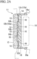
- FIG. 2A is a cross-sectional view taken along line 1A-1A of FIG. 1 .
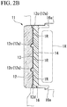
- FIG. 2B is a cross-sectional view taken along line 1B-1B of FIG. 1 .
- the radar cover 11 of the present embodiment has an emblem 1E disposed at the center and a mesh-like outer design portion 1D disposed around the emblem 1E.
- a portion of the emblem 1E and a portion of the outer design portion 1D are illustrated in white, but the region illustrated in white is silver in the present embodiment.
- a region indicated by a dot pattern in the emblem 1E and the outer design portion 1D is black in the present embodiment.
- the radar cover 11 of the present embodiment is disposed so as to cover a radar unit 1X for detecting a surrounding situation of a vehicle from a front side of the vehicle, and transmits a radio wave used in the radar unit 1X.
- a radar cover 11 of the present embodiment is disposed on a path of a radio wave of the radar unit 1X (in a region through which a radio wave emitted from the radar unit 1X is propagated), and includes, a transparent member 12, a print layer 13, a paint layer 14, an inner core 15 (colored core), and a support member 16 as illustrated in FIGS. 2A and 2B .
- the up-down direction on the sheet in FIGS. 1 , 2A , and 2B is simply referred to as an up-down direction.
- the up-down direction is the same as the vertical direction when the radar cover 11 is installed in a vehicle.
- the transparent member 12 is formed of a transparent resin material and is disposed at the outermost side of a vehicle among constituent members of the radar cover 11.
- a front surface of the transparent member 12 is formed in a smooth surface in order to enhance visibility of the emblem 1E and the outer design portion 1D when viewed from the outside of the vehicle.
- On a back side of the transparent member 12 (a side facing the support member 16, back surface), a recess 12a is formed.
- the transparent member 12 includes, as the recess 12a, an inner core housing recess 12b (housing recess) having the inner core 15 housed therein, and a painted recess 12c having the paint layer 14 formed therein by application of a paint to the inner wall surface.
- a surface of the transparent member 12 on a side of the radar unit 1X is referred to as a back surface, and the surface opposite thereto is referred to as a front surface (front).
- a side on which a back surface of the transparent member 12 is located may be referred to as a back side, and a side on which a front surface thereof is located may be referred to as a front side.
- a direction in which the front surface and the back surface of the transparent member 12 face each other, that is, a left-right direction on the sheet in FIGS. 2A and 2B may be referred to as a thickness direction.
- the inner core housing recess 12b is formed in a circular shape when viewed from the front and is disposed at the center of the radar cover 11 on which the emblem 1E is disposed.
- a circular outer edge of the inner core housing recess 12b is disposed avoiding the character "F” illustrated in FIG. 1 , and the character “F” is located inside the circular outer edge.
- Such an inner core housing recess 12b houses the inner core 15 in a state in which the inner core 15 is in contact with the inner wall surface.
- FIG. 3 is a schematic enlarged cross-sectional view including the inner core housing recess 12b.
- a depth dimension 1d1 of the inner core housing recess 12b is set to be larger than a thickness dimension 1d2 of the inner core 15.
- the depth dimension 1d1 of the inner core housing recess 12b means a distance dimension from a bottom surface of the inner core housing recess 12b to a virtual surface 1S which is the same surface as a back surface of the transparent member 12 in a direction perpendicular to the back surface of the transparent member 12 (thickness direction).
- the depth dimension 1d1 of the inner core housing recess 12b indicates the depth distance from the back surface of the transparent member 12 of the inner core housing recess 12b recessed from the back surface of the transparent member 12 toward the front of the transparent member 12.
- the thickness dimension 1d2 of the inner core 15 means a distance dimension from a surface of the transparent member 12 of the inner core 15 on a front side thereof to a surface of the transparent member 12 of the inner core 15 on a back side thereof in a direction perpendicular to the back surface of the transparent member 12 (thickness direction). That is, the thickness dimension 1d2 of the inner core 15 indicates the thickness of the inner core 15 formed in a plate shape.
- the inner wall surface of the inner core housing recess 12b is bent at an angle of approximately 90° and connected to the back surface of the transparent member 12. That is, a boundary portion (connecting portion) between the inner wall surface (side surface) of the inner core housing recess 12b and a print layer forming region 1R has a so-called pin angle (an angle having no roundness but a sharp edge, an angular shape).
- the angle formed between the inner wall surface of the inner core housing recess 12b and the back surface of the transparent member 12 is preferably 90°, but may be about 93° in consideration of a draft during injection molding. Note that the angle may be an obtuse angle.
- the painted recess 12c has, a frame-like portion 12d disposed in a frame shape on an outer edge portion of the radar cover 11, and a mesh-like portion 12e formed in a mesh shape inside the frame-like portion 12d, when viewed from the front.
- the paint layer 14 is disposed so as to cover the inner wall surface of the painted recess 12c.
- a portion of the support member 16 enters the painted recess 12c, and the paint layer 14 is covered from the back side by the support member 16.
- a region in which the recess 12a is not formed on a surface of the transparent member 12 on a side of the support member 16 is the print layer forming region 1R where the print layer 13 is formed.
- This print layer forming region 1R is a flat surface and is covered from the back side of the transparent member 12 by the print layer 13.
- Such a transparent member 12 is formed of a transparent synthetic resin such as colorless polycarbonate (PC) or a polymethyl methacrylate resin (PMMA), for example, and has a thickness of about 1.5 mm to 10 mm.
- a front surface of the transparent member 12 may be subjected to a hard coat treatment for preventing scratches or a clear coat treatment with a urethane-based paint as necessary.
- a material of the transparent member 12 is a transparent synthetic resin having scratch resistance, the scratch preventing treatment is not necessary.
- the print layer 13 is a thin film layer printed on the print layer forming region 1R of the transparent member 12 and is black as described above in the present embodiment.
- the print layer 13 is formed by transferring black ink onto the print layer forming region 1R and drying the ink.
- the print layer 13 can be formed by putting a black resin ink capable of transmitting a radio wave used in the radar unit 1X on the print layer forming region 1R, for example, by a silk printing method and drying the ink naturally.
- Such a print layer 13 is visually recognizable from the outside through the transparent member 12 and forms a region indicated by the dot pattern illustrated in FIG. 1 .
- the paint layer 14 is a thin film layer formed by drying a silver paint capable of transmitting a radio wave used in the radar unit 1X and is silver as described above in the present embodiment.
- the paint layer 14 is disposed on the entire back surface of the transparent member 12 on which the print layer 13 is formed except for a region where the emblem 1E is formed. That is, the paint layer 14 covers a surface (surface facing the support member 16) of the print layer 13 on a side of the support member 16 except for the region where the emblem 1E is formed.
- the paint layer 14 can be formed, for example, by applying a paint containing a pearl pigment and drying the paint naturally. Such a paint layer 14 is visually recognizable from the outside through the transparent member 12 in the painted recess 12c and forms a region indicated by white of the outer design portion 1D illustrated in FIG. 1 .
- the inner core 15 has, a base formed of a resin capable of transmitting a radio wave used in the radar unit 1X, and a glittering film formed so as to cover a front surface of the base.
- the glittering film include a discontinuous metal film having many gaps (holes) capable of transmitting a radio wave formed therein, and examples thereof include an indium film formed by a sputtering method or a vacuum vapor deposition method. That is, the inner core 15 has a discontinuous metal film disposed on a surface layer thereof and capable of transmitting a radio wave. By having such a discontinuous metal film, the inner core 15 is silver.
- the inner core 15 may have a transparent top coat layer covering a front surface of the glittering film or an undercoat layer covering a back surface of the glittering film.
- Such an inner core 15 is fitted and disposed in the inner core housing recess 12b of the transparent member 12 such that the glittering film of the inner core 15 faces the inner wall surface of the inner core housing recess 12b.
- Such an inner core 15 is visually recognizable from the outside through the transparent member 12 and forms a region indicated by white of the emblem 1E illustrated in FIG. 1 .
- the front surface of the inner core 15 is in contact with a bottom surface (front inner surface) of the inner core housing recess 12b.
- the thickness dimension 1d2 of the inner core 15 is set to be smaller than the depth 1d1 of the inner core housing recess 12b. Therefore, when the transparent member 12 and the inner core 15 are viewed as an integrated body (integrated structure), a recess is formed on a back surface of the integrated body.
- the support member 16 is a portion bonded to the back surface of the transparent member 12 and supporting the transparent member 12, and is formed of a black resin material.
- the support member 16 has an engaging portion 16a protruding toward a side of an engine room.
- the engaging portion 16a has a claw-shaped distal end portion, and the distal end portion is engaged, for example, with a radiator grill main body.
- the support member 16 has a protrusion 16b housed in the inner core housing recess 12b and bonded to the back surface of the inner core 15.
- the protrusion 16b which is a portion of the support member 16 is filled in a region where the inner core 15 is not disposed (region from the inner core 15 to the virtual surface IS illustrated in FIG. 3 ) out of a space surrounded by the inner core housing recess 12b of the transparent member 12.
- the protrusion 16b is located on the opposite side to the bottom surface of the inner core housing recess 12b with the inner core 15 interposed therebetween.
- the protrusion 16b of the support member 16 is formed in the entire region forming the inner core housing recess 12b when viewed from the front side of the transparent member 12. Therefore, the protrusion 16b of the support member 16 is connected to the inner wall surface of the inner core housing recess 12b over the entire region in a circumferential direction thereof.
- Such a support member 16 is formed of a synthetic resin such as an acrylonitrile/butadiene/styrene copolymer synthetic resin (ABS), an acrylonitrile/ethylene/styrene copolymer synthetic resin (AES), acrylonitrile/styrene/acrylate (ASA), polybutylene terephthalate (PBT), a colored PC, or polyethylene terephthalate (PET), or a composite resin thereof, and has a thickness of about 1.0 mm to 10 mm.
- ABS acrylonitrile/butadiene/styrene copolymer synthetic resin
- AES acrylonitrile/ethylene/styrene copolymer synthetic resin
- ASA acrylonitrile/styrene/acrylate
- PBT polybutylene terephthalate
- PET polyethylene terephthalate
- the transparent member 12 is formed.
- FIG. 4A is a cross-sectional view at the same position as FIG. 2A
- FIG. 4B is a cross-sectional view at the same position as FIG. 2B
- the transparent member 12 is formed by injection molding using a die 110.
- the die 110 has a fixed side cavity die 111 and a moving side core die 112.
- the core die 112 has, a base 112a forming the print layer forming region 1R, and a nest 112b for forming the recess 12a.
- the nest 112b is separated from the base 112a of the core die 112 and protrudes from a front surface of the base 112a toward a side of the cavity die 111 in a state of being fixed to the base 112a.
- a front surface of the base 112a and a front surface of the nest 112b can be bent and connected to each other to form the transparent member 12 in which the print layer forming region 1R and the inner wall surface of the recess 12a are bent and connected to each other.
- the depth dimension 1d1 of the inner core housing recess 12b of the transparent member 12 is set to be larger than the thickness dimension 1d2 of the inner core 15 (see FIG. 3 ). That is, such a step illustrated in FIG. 4 corresponds to a transparent member forming step of forming the transparent member 12 having the inner core housing recess 12b in which the depth dimension 1d1 is set to be larger than the thickness dimension 1d2 of the inner core 15.
- FIGS. 5A and 5B the print layer 13 is formed.
- FIG. 5A is a cross-sectional view at the same position as FIG. 2A
- FIG. 5B is a cross-sectional view at the same position as FIG. 2B .
- the print layer 13 is formed by transferring ink onto the print layer forming region 1R which is a region except for the recess 12a of the transparent member 12 by a printing method such as a silk printing method and drying the ink.
- the print layer forming region 1R and the inner wall surface of the recess 12a are bent and connected to each other.
- the ink transferred onto the print layer forming region 1R has more difficulty in moving to the inner wall surface of the recess 12a than a case where the print layer forming region 1R and the inner wall surface of the recess 12a are connected with a smooth curved surface. According to such a method for manufacturing the radar cover 11 of the present embodiment, it is possible to prevent unintentional meandering of an end portion of the print layer 13.
- FIG. 6A is a cross-sectional view at the same position as FIG. 2A
- FIG. 6B is a cross-sectional view at the same position as FIG. 2B .
- a silver mica paint is sprayed, for example, on a back side of the transparent member 12 on which the print layer 13 is formed, and the mica paint is dried to form the paint layer 14.
- the paint layer 14 covering the print layer 13 and directly adhering to the inner wall surface of the entire painted recess 12c is formed except for the region where the emblem 1E is formed.
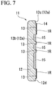
- FIG. 7 is a cross-sectional view at the same position as FIG. 2A .
- the inner core 15 formed in parallel to formation of the above-described transparent member 12, print layer 13, or paint layer 14 is housed in the inner core housing recess 12b.
- the inner core 15 is formed by forming a glittering discontinuous metal film such as an indium layer on a base formed by injection molding in advance by a vacuum vapor deposition method, a sputtering method, or the like. Note that a topcoat layer or an undercoat layer is formed as necessary in the inner core 15.
- Such an inner core 15 is housed in the inner core housing recess 12b with the glittering discontinuous metal film facing a side of the inner wall surface of the inner core housing recess 12b in a state of being in contact with a bottom of the inner core housing recess 12b.
- Such a step illustrated in FIG. 7 disposes the inner core 15 in a state of being in contact with the bottom of the inner core housing recess 12b, corresponding to the colored core disposing step in the present embodiment.
- the depth dimension 1d1 of the inner core housing recess 12b of the transparent member 12 is set to be larger than the thickness dimension 1d2 of the inner core 15 (see FIG. 3 ). Therefore, when the inner core 15 is housed in the inner core housing recess 12b, the region from the back surface of the inner core 15 to the virtual surface IS illustrated in FIG. 3 is a space where the inner core 15 does not exist.
- FIGS. 8A and 8B the support member 16 is formed.
- FIG. 8A is a cross-sectional view at the same position as FIG. 2A
- FIG. 8B is a cross-sectional view at the same position as FIG. 2B .
- the transparent member 12 having the inner core 15 disposed in the inner core housing recess 12b is disposed inside a die for injection molding, and insert molding for emitting a molten resin to the back side of the transparent member 12 is performed to form the support member 16.
- Such a support member 16 is welded to the transparent member 12 by heat during insert molding and disposed so as to cover the inner core 15. As a result, the inner core 15 is fixed to the transparent member 12.
- the inner wall surface of the inner core housing recess 12b protrudes beyond the back surface of the inner core 15, and it is possible to prevent the inner core 15 from flowing out of the inner core housing recess 12b when a material for forming the support member 16 is poured into the inner core housing recess 12b.
- the molten resin flows into and fills a region where the inner core 15 does not exist out of a space surrounded by the inner core housing recess 12b, and this portion is cooled to form the protrusion 16b.
- Such a step illustrated in FIGS. 8A and 8B forms the support member 16 on the back side of the transparent member 12 by injection molding, corresponding to the support member forming step in the present embodiment.
- the depth dimension 1d1 of the inner core housing recess 12b formed on the back side of the transparent member 12 is set to be larger than the thickness dimension 1d2 of the inner core 15. Therefore, even when the inner core 15 is housed in the inner core housing recess 12b, not the whole of the inner core housing recess 12b is filled with the inner core 15, and there is a region where the inner core 15 does not exist in a portion of the inner core housing recess 12b on a side of the support member 16. Furthermore, in the radar cover 11 of the present embodiment, the support member 16 is filled in a region where the inner core 15 does not exist in the inner core housing recess 12b.
- the entire back surface of the inner core 15 is reliably in close contact with the support member 16, and the entire area of a side surface of the inner core 15 is in contact with the inner wall surface of the inner core housing recess 12b. Therefore, it is possible to reliably prevent displacement of the inner core 15 with respect to the transparent member 12.
- the protrusion 16b of the support member 16 enters the inner core housing recess 12b. Therefore, a coupling force between the transparent member 12 and the support member 16 is enhanced, and separation of the transparent member 12 from the support member 16 can be suppressed.
- the support member 16 is formed by injection molding in a state where the inner core 15 is housed in the inner core housing recess 12b of the transparent member 12. At this time, the entire inner core 15 is reliably housed inside the inner core housing recess 12b, and the back surface of the inner core 15 is disposed on an inner side of a back surface of the transparent member 12 (on a front side of the transparent member 12).
- the inner wall surface of the inner core housing recess 12b protrudes beyond the back surface of the inner core 15, and it is possible to reliably prevent the inner core 15 from flowing out of the inner core housing recess 12b when a material for forming the support member 16 is poured into the inner core housing recess 12b. Therefore, according to the method for manufacturing the radar cover 11 of the present embodiment, it is possible to reliably prevent displacement of the inner core 15 with respect to the transparent member 12.
- the inner wall surface of the inner core housing recess 12b is bent and connected to the back surface of the transparent member 12. This makes it possible to more reliably prevent the inner core 15 from flowing out of the inner core housing recess 12b as compared with a case where the inner wall surface of the inner core housing recess 12b is curved and smoothly connected to the back surface of the transparent member 12.
- the radar cover 11 and the method for manufacturing the radar cover 11 according to the present embodiment it is possible to reliably prevent displacement of the inner core 15 with respect to the transparent member 12 as described above. Therefore, when a discontinuous metal film capable of transmitting a radio wave is formed on a surface layer of the inner core 15, it is possible to prevent the discontinuous metal film from being rubbed against the inner wall surface of the transparent member 12 to be scratched.
- the present invention is not limited thereto, and can also adopt a configuration in which in only a portion of the region forming the inner core housing recess 12b when viewed from the front side of the transparent member 12, a region where the inner core 15 is not disposed out of a space surrounded by the inner core housing recess 12b is formed.
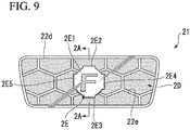
- FIG. 9 is a front view schematically illustrating a radar cover 21 of the present embodiment.
- FIG. 10 is a partially enlarged view of the transparent member 22 and the inner core 25.
- the inner core housing recess 22b described later is indicated by a solid line, and the painted recess 22c described later is omitted.
- FIG. 11 is a cross-sectional view taken along line 2A-2A of FIG. 9 .
- the radar cover 21 of the present embodiment has, an emblem 2E disposed at the center, and a mesh-like outer design portion 2D disposed around the emblem 2E.
- FIG. 10 is a partially enlarged view of the transparent member 22 and the inner core 25.
- the inner core housing recess 22b described later is indicated by a solid line, and the painted recess 22c described later is omitted.
- FIG. 11 is a cross-sectional view taken along line 2A-2A of FIG. 9 .
- the radar cover 21 of the present embodiment has, an emblem 2E disposed at the center
- a portion of the emblem 2E and a portion of the outer design portion 2D are illustrated in white, but the region illustrated in white is silver in the present embodiment.
- a region indicated by a dot pattern in the emblem 2E and the outer design portion 2D is black in the present embodiment.
- the radar cover 21 of the present embodiment is disposed so as to cover a radar unit 2X for detecting a surrounding situation of a vehicle from a front side of the vehicle, and transmits a radio wave used in the radar unit 2X.
- a radar cover 21 of the present embodiment is disposed on a travelling path of a radio wave of the radar unit 2X (in a region through which a radio wave emitted from the radar unit 2X is propagated), and includes, a transparent member 22, a print layer 23, a paint layer 24, an inner core 25 (colored core), and a support member 26 as illustrated in FIG. 11 .
- the up-down direction on the sheet in FIGS. 9 , 10 , and 11 is simply referred to as an up-down direction.
- the up-down direction is the same as the vertical direction when the radar cover 21 is installed in a vehicle.
- the transparent member 22 is formed of a transparent resin material and is disposed at the outermost side of a vehicle among constituent members of the radar cover 21.
- a front surface of the transparent member 22 is formed in a smooth surface in order to enhance visibility of the emblem 2E and the outer design portion 2D as viewed from the outside of the vehicle.
- On a back surface of the transparent member 22 (a surface on a side of the support member 26), a recess 22a is formed.
- the transparent member 22 includes, as the recess 22a, an inner core housing recess 22b having the inner core 25 housed therein, and a painted recess 22c having the paint layer 24 formed therein by application of a paint to the inner wall surface.
- a surface of the transparent member 22 on a side of the radar unit 2X is referred to as a back surface, and the surface opposite thereto is referred to as a front surface (front).
- a side on which a back surface of the transparent member 22 is located may be referred to as a back side, and a side on which a front surface thereof is located may be referred to as a front side.
- a direction in which the front surface and the back surface of the transparent member 22 face each other, that is, a left-right direction on the sheet in FIG. 11 may be referred to as a thickness direction.
- the inner core housing recess 22b is formed in a shape along the outer shape of the emblem 2E when viewed from the front and is formed at the center of the radar cover 21 on which the emblem 2E is disposed.
- the opening shape of the inner core housing recess 22b is slightly larger than the outer shape of the inner core 25 in order to make it possible to house the inner core 25 therein.
- the painted recess 22c has, a frame-like portion 22d formed in a frame shape on an outer edge portion of the radar cover 21, and a mesh-like portion 22e formed in a mesh shape inside the frame-like portion 22d, when viewed from the front.
- the paint layer 24 is disposed so as to cover the inner wall surface.
- Part of the support member 26 enters the painted recess 22c, and the paint layer 24 is covered from the back side by the support member 26.
- a region in which the recess 22a is not formed on a surface (back surface) of the transparent member 22 on a side of the support member 26 is the print layer forming region 2R where the print layer 23 is formed.
- This print layer forming region 2R is a flat surface and is covered from the back side of the transparent member 22 by the print layer 23.
- the transparent member 22 has a protrusion 22f protruding from a bottom of the inner core housing recess 22b.
- the protrusion 22f is erected on the bottom of the inner core housing recess 22b so as to protrude from the front side of the transparent member 22 to the back side thereof.
- the distal end surface of the protrusion 22f is a flat surface and is formed so as to be a print layer forming surface on which the print layer 23 is formed. Note that the distal end surface of the protrusion 22f is closer to the front side of the transparent member 22 than the print layer forming region 2R which is the back surface of the transparent member 22 (closer to the front). That is, the protrusion dimension of the inner core housing recess 22b of the protrusion 22f from the bottom is set to be smaller than the depth dimension of the inner core housing recess 22b.
- the transparent member 22 has a plurality of protrusions 22g formed on the inner wall surface of the recess 22a as illustrated in FIG. 10 . These protrusions 22g are configured to position the inner core 25 in the inner core housing recess 22b. Details of these protrusions 22g will be described later in detail.
- Such a transparent member 22 is formed of a transparent synthetic resin such as colorless polycarbonate (PC) or a polymethyl methacrylate resin (PMMA), for example, and has a thickness of about 1.5 mm to 10 mm.
- a front surface of the transparent member 22 may be subjected to a hard coat treatment for preventing scratches or a clear coat treatment with a urethane-based paint as necessary.
- a material of the transparent member 22 is a transparent synthetic resin having scratch resistance, the scratch preventing treatment is not necessary.
- the print layer 23 is a thin film layer printed on the print layer forming region 2R of the transparent member 22 and the distal end surface of the protrusion 22f and is black as described above in the present embodiment.
- the print layer 23 is formed by transferring a black ink onto the print layer forming region 2R or the distal end surface of the protrusion 22f and drying the ink.
- the print layer 23 formed on the print layer forming region 2R (back surface) of the transparent member 22 (hereinafter referred to as an outer print layer 23a) can be formed by putting a black resin ink capable of transmitting a radio wave used in the radar unit 2X on the print layer forming region 2R, for example, by a silk printing method and drying the ink naturally.
- the print layer 23 formed on the distal end surface of the protrusion 22f (hereinafter referred to as an emblem print layer 23b) can be formed by putting a black resin ink capable of transmitting a radio wave used in the radar unit X on the distal end surface of the protrusion 22f, for example, by a pad printing method and drying the ink naturally.
- the outer print layer 23a and the emblem print layer 23b are visually recognizable from the outside through the transparent member 22 and form a region indicated by the dot pattern illustrated in FIG. 9 .
- the outer print layer 23a forms a portion excluding the mesh-like pattern of the outer design portion 2D.
- the emblem print layer 23b forms a character portion of "F" of the emblem 2E.
- the paint layer 24 is a thin film layer formed by drying a silver paint capable of transmitting a radio wave used in the radar unit 2X and is silver as described above in the present embodiment.
- the paint layer 24 is disposed on the entire back surface of the transparent member 22 on which the print layer 23 is formed except for a region where the emblem 2E is formed. That is, the paint layer 24 covers a surface (surface facing the support member 26) of the print layer 23 on a side of the support member 26 except for the region where the emblem 2E is formed.
- the paint layer 24 can be formed, for example, by applying a paint containing a pearl pigment and drying the paint naturally. Such a paint layer 24 is visually recognizable from the outside through the transparent member 22 in the painted recess 22c and forms a region indicated by white of the outer design portion 2D illustrated in FIG. 9 .
- the inner core 25 has, a base formed of a resin capable of transmitting a radio wave used in the radar unit 2X, and a glittering film formed so as to cover a front surface of the base.
- the glittering film include a discontinuous metal film having many gaps (holes) capable of transmitting a radio wave formed therein, and examples thereof include an indium film formed by a sputtering method or a vacuum vapor deposition method. That is, the inner core 25 has a discontinuous metal film disposed on a surface layer thereof and capable of transmitting a radio wave. By having such a discontinuous metal film, the inner core 25 is silver.
- the inner core 25 may have a transparent top coat layer covering a front surface of the glittering film or an undercoat layer covering a back surface of the glittering film.
- the inner core 25 has a groove corresponding to the protrusion 22f of the transparent member 22.
- the inner core 25 is fitted and disposed in the inner core housing recess 22b of the transparent member 22 such that the glittering film of the inner core 25 faces the inner wall surface of the inner core housing recess 22b and furthermore the protrusion 22f is fitted into the groove.
- Such an inner core 25 is visually recognizable from the outside through the transparent member 22 and forms a region indicated by white of the emblem 2E illustrated in FIG. 9 .
- the support member 26 is a portion bonded to the back surface of the transparent member 22 and supporting the transparent member 22, and is formed of a black resin material.
- the support member 26 has an engaging portion 26a protruding toward a side of an engine room.
- the engaging portion 26a has a claw-shaped distal end portion, and the distal end portion is engaged, for example, with a radiator grill main body.
- Such a support member 26 is formed of a synthetic resin such as an acrylonitrile/butadiene/styrene copolymer synthetic resin (ABS), an acrylonitrile/ethylene/styrene copolymer synthetic resin (AES), acrylonitrile/styrene/acrylate (ASA), polybutylene terephthalate (PBT), a colored PC, or polyethylene terephthalate (PET), or a composite resin thereof, and has a thickness of about 1.0 mm to 10 mm.
- ABS acrylonitrile/butadiene/styrene copolymer synthetic resin
- AES acrylonitrile/ethylene/styrene copolymer synthetic resin
- ASA acrylonitrile/styrene/acrylate
- PBT polybutylene terephthalate
- PET polyethylene terephthalate
- the emblem 2E is formed into a shape having, a circular central portion 2E1, an upper protrusion 2E2 protruding upward from the central portion 2E1 and having a linear upper edge and a linear side edge, a lower protrusion 2E3 protruding downward from the central portion 2E1 and having a linear lower edge and a linear side edge, a right protrusion 2E4 protruding to the right from the central portion 2E1 and having a linear right edge and linear upper and lower edges, and a left protrusion 2E5 protruding to the left from the central portion 2E1 and having a linear left edge and linear upper and lower edges, when viewed from the front side (when viewed from the thickness direction)
- the shapes of the inner core 25 and the inner core housing recess 22b of the transparent member 22 are set according to the shape of
- the inner core 25 is formed into a shape having, a disk-like central plate portion 25a, an upper plate portion 25b protruding upward from the central plate portion 25a and having a flat upper end surface and a flat side end surface, a lower plate portion 25c protruding downward from the central plate portion 25a and having a flat lower end surface and a flat side end surface, a right plate portion 25d protruding to the right from the central plate portion 25a and having a flat right end surface and flat upper and lower end surfaces, and a left plate portion 25e protruding to the left from the central plate portion 25a and having a flat left end surface and flat upper and lower end surfaces.
- the upper end surface and the side end surface of the upper plate portion 25b, the lower end surface and the side end surface of the lower plate portion 25c, the right end surface and the upper and lower end surfaces of the right plate portion 25d, and the left end surface and the upper and lower end surfaces of the left plate portion 25e are parallel to a thickness direction. Note that these surfaces may be inclined with respect to the thickness direction.
- the inner core housing recess 22b of the transparent member 22 is formed into a shape having, a central recess 22b1 in which the central plate portion 25a of the inner core 25 is housed, an upper recess 22b2 in which the upper plate portion 25b of the inner core 25 is housed, a lower recess 22b3 in which the lower plate portion 25c of the inner core 25 is housed, a right recess 22b4 in which the right plate portion 25d of the inner core 25 is housed, and a left recess 22b5 in which the left plate portion 25e of the inner core 25 is housed.
- the upper recess 22b2 has a flat upper wall surface 221 facing an upper end surface of the upper plate portion 25b of the inner core 25.
- the lower recess 22b3 has a flat lower wall surface 222 facing a lower end surface of the lower plate portion 25c of the inner core 25.
- the right recess 22b4 has, a flat upper wall surface 223 facing an upper end surface of the right plate portion 25d of the inner core 25, and a flat side wall surface 224 facing a right end surface of the right plate portion 25d of the inner core 25.
- the left recess 22b5 has, a flat upper wall surface 225 facing an upper end surface of the left plate portion 25e of the inner core 25, and a flat side wall surface 226 facing a left end surface of the left plate portion 25e of the inner core 25.
- the protrusions 22g are formed at five positions in total, that is, on the lower wall surface 222 of the lower recess 22b3, the upper wall surface 223 of the right recess 22b4, the side wall surface 224 of the right recess 22b4, the upper wall surface 225 of the left recess 22b5, and the side wall surface 226 of the left recess 22b5.
- Each of the protrusions 22g is disposed at the center of each of the surfaces when viewed from the front side.
- the protrusion 22g formed on the lower wall surface 222 of the lower recess 22b3 is referred to as a first protrusion 22g1
- the protrusion 22g formed on the upper wall surface 223 of the right recess 22b4 is referred to as a second protrusion 22g2
- the protrusion 22g formed on the side wall surface 224 of the right recess 22b4 is referred to as a third protrusion 22g3
- the protrusion 22g formed on the upper wall surface 225 of the left recess 22b5 is referred to as a fourth protrusion 22g4
- the protrusion 22g formed on the side wall surface 226 of the left recess 22b5 is referred to as a fifth protrusion 22g5.
- FIG. 12 is an enlarged schematic view of the protrusion 22g.
- the protrusion 22g is drawn largely so as to be visually recognizable.
- the protrusion amount of the actual protrusion 22g from the inner wall surface of the inner core housing recess 22b of the transparent member 22 to a distal end thereof is, for example, 0.1 mm or less. As illustrated in FIG.
- the protrusion 22g protrudes from an inner wall side surface of the inner core housing recess 22b (a surface connecting the bottom surface (front surface) of the inner core housing recess 22b to the print layer forming region 2R out of the inner wall surface) toward a side of the inner core 25 (a direction along the front surface of the transparent member 22), and is narrowed from a root thereof toward a distal end thereof.
- the width of the protrusion 22g when viewed from the thickness direction decreases toward a distal end thereof.
- the protrusion 22g is formed with a length from a bottom of the inner core housing recess 22b to an opening end thereof. Such a protrusion 22g positions the inner core 25 in the inner core housing recess 22b in a direction along a front surface of the transparent member 22 by bringing a distal end thereof into contact with the inner core 25.
- the first protrusion 22g1 regulates movement of the inner core 25 downward with respect to the transparent member 22 by bringing a distal end thereof into contact with the lower end surface of the lower plate portion 25c of the inner core 25.
- the second protrusion 22g2 regulates movement of the inner core 25 upward with respect to the transparent member 22 by bringing a distal end thereof into contact with the upper end surface of the right plate portion 25d of the inner core 25.
- the third protrusion 22g3 regulates movement of the inner core 25 to the right with respect to the transparent member 22 by bringing a distal end thereof into contact with the right end surface of the right plate portion 25d of the inner core 25.
- the fourth protrusion 22g4 regulates movement of the inner core 25 upward with respect to the transparent member 22 by bringing a distal end thereof into contact with the upper end surface of the left plate portion 25e of the inner core 25.
- the fifth protrusion 22g5 regulates movement of the inner core 25 to the left with respect to the transparent member 22 by bringing a distal end thereof into contact with the left end surface of the left plate portion 25e of the inner core 25.
- the first protrusion 22g1, the second protrusion 22g2, and the fourth protrusion 22g4 regulate movement (linear movement) of the inner core 25 with respect to the transparent member 22 in the up-down direction, and position the inner core 25 in the inner core housing recess 22b in the up-down direction.
- the first protrusion 22g1, the second protrusion 22g2, and the fourth protrusion 22g4 regulate rotation of the inner core 25 with respect to the transparent member 22 when viewed from a direction orthogonal to a front surface of the transparent member 22, and position the inner core 25 in the inner core housing recess 22b in the rotation direction.
- each of the first protrusion 22g1, the second protrusion 22g2, and the fourth protrusion 22g4 functions as both a rotation regulating protrusion for regulating movement of the inner core 25 with respect to the transparent member 22 in a rotation direction when viewed from a direction orthogonal to a front surface of the transparent member 22 (rotation direction around an axis intersecting with a front surface of the transparent member 22) and a linear movement regulating protrusion (first linear movement regulating protrusion) for regulating movement of the inner core 25 with respect to the transparent member 22 in a linear direction along the front surface of the transparent member 22.
- the third protrusion 22g3 and the fifth protrusion 22g5 regulate movement (linear movement) of the inner core 25 with respect to the transparent member 22 in the left-right direction, and position the inner core 25 in the inner core housing recess 22b in the left-right direction. That is, each of the third protrusion 22g3 and the fifth protrusion 22g5 functions as a linear movement regulating protrusion (second linear movement regulating protrusion) for regulating movement of the inner core 25 with respect to the transparent member 22 in a linear direction along the front surface of the transparent member 22.
- the inner core 25 is positioned by these protrusions 22g.
- a minute gap corresponding to the protrusion amount of each of the protrusions 22g is formed between the lower wall surface 222 of the lower recess 22b3 and the lower end surface of the lower plate portion 25c of the inner core 25, between the upper wall surface 223 of the right recess 22b4 and the upper end surface of the right plate portion 25d of the inner core 25, between the side wall surface 224 of the right recess 22b4 and the right end surface of the right plate portion 25d of the inner core 25, between the upper wall surface 225 of the left recess 22b5 and the upper end surface of the left plate portion 25e of the inner core 25, and between the side wall surface 226 of the left recess 22b5 and the left end surface of the left plate portion 25e of the inner core 25.
- the protrusion 22g is not formed on the upper wall surface 221 of the upper recess 22b2 which is the uppermost surface of the inner core housing recess 22b. Therefore, the upper end surface of the upper plate portion 25b of the inner core 25 is in surface contact with the upper wall surface 221 of the upper recess 22b2.
- the inner core housing recess 22b is formed to be larger than the inner core 25, a gap is generated at any position between the inner core 25 and the inner wall surface of the inner core housing recess 22b.
- the protrusion 22g positions the inner core 25 in the inner core housing recess 22b.
- the transparent member 22 is formed.
- FIG. 13 is a cross-sectional view at the same position as FIG. 11 .
- the transparent member 22 is formed by injection molding using a die 210.
- the die 210 has a fixed side cavity die 211 and a moving side core die 212.
- the core die 212 has, a base 212a forming the print layer forming region 2R, and a nest 212b for forming the recess 22a.
- the nest 212b is separated from the base 212a of the core die 212 and protrudes from a front surface of the base 212a toward a side of the cavity die 211 in a state of being fixed to the base 212a.
- the protrusion 22g for positioning the inner core 25 is formed in the step illustrated in FIG. 13 .
- FIGS. 14 and 15 are cross-sectional views at the same position as FIG. 11 .
- ink is transferred onto the print layer forming region 2R of the transparent member 22 by a printing method such as a silk printing method, and the ink is dried to form the outer print layer 23a.
- ink is transferred onto the distal end surface of the protrusion 22f by a pad printing method, and the ink is dried to form the emblem print layer 23b.
- ink is transferred from a metallic die onto a silicon pad 2P, and furthermore the pad 2P is pressed against the distal end surface of the protrusion 22f to transfer the ink onto the distal end surface of the protrusion 22f.
- FIG. 16 is a cross-sectional view at the same position as FIG. 11 .
- a silver mica paint is sprayed, for example, on a back side of the transparent member 22 on which the print layer 23 is formed, and the mica paint is dried to form the paint layer 24.
- the paint layer 24 thus formed covers the print layer 23 and directly adheres to the inner wall surface of the entire painted recess 22c except for the region where the emblem 2E is formed.
- the inner core 25 is housed in the inner core housing recess 22b.
- FIG. 17 is a cross-sectional view at the same position as FIG. 11 .
- the inner core 25 formed in parallel to formation of the above-described transparent member 22, print layer 23, or paint layer 24 is housed in the inner core housing recess 22b.
- the inner core 25 is formed by forming a glittering discontinuous metal film such as an indium layer on a base formed by injection molding in advance by a vacuum vapor deposition method, a sputtering method, or the like. Note that a topcoat layer or an undercoat layer is formed as necessary in the inner core 25.
- Such an inner core 25 is housed in the inner core housing recess 22b with the glittering discontinuous metal film facing a side of the inner wall surface of the inner core housing recess 22b.
- FIG. 18 is a cross-sectional view at the same position as FIG. 11 .
- the transparent member 22 having the inner core 25 disposed in the inner core housing recess 22b is disposed inside a die for injection molding, and insert molding for emitting a molten resin to the back side of the transparent member 22 is performed to form the support member 26.
- Such a support member 26 is welded to the transparent member 22 by heat during insert molding and disposed so as to cover the inner core 25. As a result, the inner core 25 is fixed to the transparent member 22.
- the protrusion 22g formed in the transparent member 22 positions the inner core 25 with respect to the transparent member 22 in a direction along a front surface of the transparent member 22. Therefore, it is possible to accurately position the inner core 25 in the inner core housing recess 22b of the transparent member 22. For example, it is possible to prevent an unintentional change in an important portion in the design of the radar cover 21.
- a region where the character "F" of the emblem 2E is formed is a position that is most easily caught by a person's attention and is the most important portion in the design of the radar cover 21. If a positional relationship between the distal end surface of the protrusion 22f of the transparent member 22 on which the print layer 23 is formed and the groove of the inner core 25 where the protrusion 22f is formed is displaced with respect to a normal position in the region where the character "F" is formed, failure in design may occur, for example, an edge of the character "F” visually recognized from the outside appears slightly double due to an influence of reflection on the inner wall surface of the groove or the like.
- the design at an important position may unintentionally change slightly.
- the radar cover 21 of the present embodiment since the inner core 25 is positioned with respect to the transparent member 22 by the protrusions 22g, it is possible to prevent displacement of the inner core 25 with respect to the transparent member 22 and to prevent a design change in the region where the character "F" important in design is formed.
- the protrusion 22g is formed on a flat surface of the transparent member 22. Therefore, as compared with a case where the protrusion 22g is formed on a curved surface, it is possible to easily form the protrusion 22g and to dispose a distal end surface of the protrusion 22g at a desired position. Since the protrusion 22g is formed so as to be narrowed from a root thereof toward a distal end thereof, the contact area between the protrusion 22g and the inner core 25 is reduced, the inner core 25 is easily disposed in the inner core housing recess 22b, and the inner core 25 can be accurately positioned.
- the radar cover 21 of the present embodiment has, the rotation regulating protrusion (first protrusion 22g1, second protrusion 22g2, and fourth protrusion 22g4) for regulating movement of the inner core 25 with respect to the transparent member 22 in a rotation direction when viewed from a direction orthogonal to a front surface of the transparent member 22, and a linear movement regulating protrusion (first protrusion 22g1 to fifth protrusion 22g5) for regulating movement of the inner core 25 with respect to the transparent member 22 in a linear direction along the front surface of the transparent member 22. Therefore, movement of the inner core 25 along the front surface of the transparent member 22 can be regulated more reliably.
- the protrusion 22g is formed so as to protrude from the inner wall side surface of the inner core housing recess 22b of the transparent member 22 in a direction along the front surface of the transparent member 22.
- the protrusion 22g is formed avoiding the upper wall surface 221 which is the uppermost surface of the inner core housing recess 22b. Therefore, the upper wall surface 221 is in contact with the uppermost surface of the inner core 25, and no gap is generated between the upper wall surface 221 and the uppermost surface of the inner core 25.
- a person who visually recognizes the emblem 2E views the emblem 2E in such a manner that the person looks down on the emblem 2E obliquely from above. Therefore, the eyes tend to be focused on the vicinity of the upper wall surface 221.
- there is no gap between the upper wall surface 221 and the uppermost surface of the inner core 25 there is no gap between the upper wall surface 221 and the uppermost surface of the inner core 25. Therefore, it is possible to prevent an edge of the emblem 2E from appearing double at the portion on which the eyes are focused, and a person viewing the emblem 2E does not feel strangeness.
- a plurality of protrusions 22g is formed symmetrically when viewed from the front side (direction orthogonal to a front surface of the transparent member 22). Therefore, a gap formed between the inner core 25 and the inner wall side surface of the inner core housing recess 22b is also symmetrical.
- the outer shape of the emblem 2E is symmetrical. Therefore, since the gap formed between the inner core 25 and the inner wall side surface of the inner core housing recess 22b is also symmetrical, the gap is also recognized as a portion of design, and it is possible to prevent a person viewing the emblem 2E from feeling strangeness.
- the protrusion 22g is formed such that the protrusion amount thereof is, for example, 0.1 mm or less. This makes it possible to make the protrusion 22g less conspicuous in design and to reduce the gap formed between the inner core 25 and the inner wall side surface of the inner core housing recess 22b. This prevents an edge of the emblem 2E from appearing double, and a person viewing the emblem 2E does not feel strangeness.
- the configuration in which the protrusion 22g is formed as a portion of the transparent member 22 has been described.
- the present invention is not limited thereto.
- a protrusion may be formed on each of the transparent member 22 and the inner core 25.
- a protrusion having functions equivalent to those of the protrusions 22g3 and 22g5 of the above embodiment may be formed on the inner core 25.
- the present invention is not limited thereto, and can adopt a configuration in which protrusions of different shapes are formed.
- the shape of the protrusion when viewed from the thickness direction may be a triangle, an arc, or a rectangle with a narrow width.
- the important portion in the design of the emblem 2E is the region where the character "F" is formed.
- the important portion in the radar cover 21 is not necessarily limited to the portion where a character is formed.
- an impressive figure or pattern may be an important portion in design of a radar cover.
- a portion having an impressive shape may be an important portion in design of a radar cover.
Landscapes
- Engineering & Computer Science (AREA)
- Radar, Positioning & Navigation (AREA)
- Remote Sensing (AREA)
- Physics & Mathematics (AREA)
- Mechanical Engineering (AREA)
- Computer Networks & Wireless Communication (AREA)
- General Physics & Mathematics (AREA)
- Electromagnetism (AREA)
- Manufacturing & Machinery (AREA)
- Radar Systems Or Details Thereof (AREA)
- Injection Moulding Of Plastics Or The Like (AREA)
- Details Of Aerials (AREA)
Abstract
Description
- The present invention relates to a radar cover and a method for manufacturing the radar cover.
- The present application claims priority based on Japanese Patent Application No.
2016-252957 filed on December 27, 2016 2017-005813 filed on January 17, 2017 - In recent years, a radar unit for detecting an obstacle or the like around a vehicle using a radio wave such as a millimeter wave has been mounted on the vehicle. Generally, a radar unit is installed in a state in which the radar unit is covered with a radar cover to which a decoration such as an emblem has been applied. Such a radar unit transmits and receives a radio wave that has passed through the radar cover. Therefore, for example, as disclosed in Patent Documents 1 and 2, of course, it is necessary to form the radar cover so as to transmit a radio wave.
- Patent Document 3 discloses a radar cover in which an inner core having a metallic discontinuous film formed on a surface layer thereof is housed in a housing recess formed on a back surface of a transparent member, and a support member is bonded to the back surface of the transparent member. A radar cover having such an inner core is manufactured by integrating the inner core housed in the housing recess with the support member by injection molding. For example, Patent Document 3 discloses a method for simply manufacturing a radar cover having an emblem or the like by sandwiching a glittering member serving as a colored core between a transparent member and a support member.
-
- [Patent Document 1] Japanese Unexamined Patent Application, First Publication No.
2015-99081 - [Patent Document 2] Japanese Unexamined Patent Application, First Publication No.
2016-80479 - [Patent Document 3] Japanese Unexamined Patent Application, First Publication No.
2011-46183 - By the way, in a radar cover having an inner core, by including a metallic discontinuous film on a surface layer thereof, an inner core (colored core) having a silver front surface forms a portion of an emblem or the like visually recognizable from the outside. When the position of such a colored core with respect to the transparent member is displaced from an original reference position, impression of the emblem or the like visually recognized from the outside unintentionally changes.
- The present invention has been made in view of the above circumstances, and an object of the present invention is, in a radar cover having a colored core, to prevent displacement of a positional relationship between a transparent member and a colored core from a reference position and to prevent change of impression of an emblem or the like that has been applied to the radar cover.
- In Patent Document 3, a radar cover is manufactured by insert molding for forming a support member on a back surface of a transparent member by injection molding in a state in which a colored core is housed in a recess formed on the back surface of the transparent member. In such a radar cover, it is necessary to make the opening shape of the recess of the transparent member slightly larger than the outer shape of the colored core in order to make it possible to house the colored core in the recess of the transparent member.
- A size difference between the recess of the transparent member and the colored core is extremely small. Therefore, in general, the position of the colored core in the recess does not cause such a difference in design that can be recognized by an outside person. However, an emblem or the like of a vehicle manufacturer may include a portion that is particularly easily caught by a person's attention, such as a character or a characteristic graphic. Such a portion is often extremely important in terms of a brand image strategy of a vehicle manufacturer or the like. Therefore, in a particularly important portion, it is desirable that there is no intentional difference in design even if an expert identifies the portion. However, depending on the position of the colored core in the recess in a direction along a front surface of the transparent member, an unintentional change in design may slightly occur in an important portion, for example, an edge of a character or the like appears slightly double lines.
- The present invention has been achieved in view of the above circumstances, and an object of the present invention is, in a radar cover having a colored core housed in a recess formed on a back surface of a transparent member, to further improve arrangement precision of the colored core with respect to the transparent member and to prevent an unintentional change in design in a particularly important portion of the radar cover.
- The present invention adopts the following configuration as a means for solving the above problems.
- A radar cover according to a first aspect of the present invention is disposed on a path of a radio wave of a radar unit for detecting a surrounding situation of a vehicle, and includes, a plate-like transparent member having a housing recess recessed toward the front and formed on a back surface thereof, a colored core housed in the housing recess in a state of being in contact with a bottom surface of the housing recess, and a support member bonded to the back surface of the transparent member. In at least a portion of a region forming the housing recess when viewed from a front side of the transparent member, the depth dimension of the housing recess is set to be larger than the thickness dimension of the colored core, and a portion of the support member is filled in a region where the colored core is not disposed in a space surrounded by the housing recess.
- In the first aspect, the inner wall surface of the housing recess may be bent and connected to the back surface of the transparent member.
- In the first aspect, the colored core may have a discontinuous metal film disposed on a surface layer thereof and capable of transmitting the radio wave.
- A method for manufacturing a radar cover according to a second aspect of the present invention is a method for manufacturing a radar cover disposed on a path of a radio wave of a radar unit for detecting a surrounding situation of a vehicle. The radar cover includes, a plate-like transparent member having a housing recess recessed toward the front and formed on a back surface thereof, a colored core housed in the housing recess in a state of being in contact with a bottom surface of the housing recess, and a support member bonded to the back surface of the transparent member. The method includes, a transparent member forming step of forming the transparent member having the housing recess in which the depth dimension is set to be larger than the thickness dimension of the colored core in at least a portion of a region forming the housing recess when viewed from a front side of the transparent member, a colored core disposing step of disposing the colored layer in the housing recess in a state of being in contact with a bottom of the housing recess, and a support member forming step of forming the support member on a back side of the transparent member by injection molding.
- In the second aspect, in the transparent member forming step, the transparent member in which the inner wall surface of the housing recess is bent and connected to the back surface may be formed.
- In the second aspect, in the colored core disposing step, the colored core having a discontinuous metal film capable of transmitting the radio wave on a surface layer thereof may be disposed in the housing recess.
- A radar cover according to a third aspect of the present invention includes, a transparent member having a recess formed on a back surface thereof, a colored core housed in the recess, and a support member bonded to the back surface of the transparent member and supporting the transparent member. At least one of the transparent member and the colored core has a protrusion for positioning the colored core with respect to the transparent member in a direction along a front surface of the transparent member.
- In the third aspect, the protrusion may be disposed on either one of a flat surface disposed on the transparent member and a flat surface disposed on the colored core.
- In the third aspect, the protrusion may be formed so as to be narrowed from a root thereof toward a distal end thereof.
- In the third aspect, as the protrusion, a rotation regulating protrusion for regulating movement of the colored core with respect to the transparent member in a rotation direction around an axis intersecting with a front surface of the transparent member, and a linear movement regulating protrusion for regulating movement of the colored core with respect to the transparent member in a linear direction along the front surface of the transparent member may be included.
- In the third aspect, the protrusion may be formed so as to protrude in a direction along a front surface of the transparent member from an inner wall side surface of the recess.
- In the third aspect, the protrusion may be formed so as to avoid the uppermost surface of the recess and the uppermost surface of the colored core.
- In the third aspect, the protrusion amount of the protrusion may be 0.1 mm or less.
- In the first and second aspects of the present invention, the depth dimension of the housing recess formed on a back surface of the transparent member is set to be larger than the thickness dimension of the colored core. Therefore, even when the colored core is housed in the housing recess, the whole of the housing recess is not filled with the colored core, and there is a region where the colored core does not exist in a portion of the housing recess on a side of the support member (a region close to the support member). Furthermore, in each of the above aspects of the present invention, the support member is filled in a region where the colored core does not exist in the housing recess. According to each of the above aspects of the present invention, the entire back surface of the colored core is reliably in close contact with the support member, and the entire area of a side surface of the colored core is in contact with the housing recess. Therefore, it is possible to reliably prevent displacement of the colored core with respect to the transparent member.
- Furthermore, in each of the above aspects of the present invention, in manufacturing the radar cover, the support member is formed by injection molding in a state in which the colored core is housed in the housing recess of the transparent member. At this time, the entire colored core is reliably housed inside the housing recess, and a back surface of the colored core is disposed on an inner side of a back surface of the transparent member (on a front side of the transparent member). As a result, the inner wall surface of the housing recess protrudes to a position higher than the colored core (a position protruding toward a side of the support member beyond the back surface of the colored core). When a material for forming the support member is poured into the housing recess, it is possible to reliably prevent the colored core from flowing out of the housing recess. Therefore, according to each of the above aspects of the present invention, it is possible to reliably prevent displacement of the colored core with respect to the transparent member.
- Therefore, according to each of the above aspects of the present invention, in the radar cover having the colored core, it is possible to prevent displacement of a positional relationship between the transparent member and the colored core from a reference position and to prevent change of impression of an emblem or the like that has been applied to the radar cover.
- Furthermore, according to the third aspect of the present invention, the protrusion formed in the transparent member or the colored core positions the colored core with respect to the transparent member in a direction along a front surface of the transparent member. Therefore, it is possible to accurately position the colored core in the recess of the transparent member. For example, it is possible to prevent an unintentional change in an important portion in the design of the radar cover. Therefore, according to the above aspects of the present invention, in the radar cover having the colored core housed in the recess formed on the back surface of the transparent member, it is possible to further improve arrangement precision of the colored core with respect to the transparent member and to prevent an unintentional change in design in a particularly important portion of the radar cover.
-
-
FIG. 1 is a front view schematically illustrating a radar cover according to a first embodiment of the present invention. -
FIG. 2A is a cross-sectional view taken alongline 1A-1A ofFIG. 1 . -
FIG. 2B is a cross-sectional view taken alongline 1B-1B ofFIG. 1 . -
FIG. 3 is a schematic enlarged cross-sectional view including an inner core housing recess 2b included in the radar cover according to the first embodiment of the present invention. -
FIG. 4A is a schematic view for explaining a method for manufacturing the radar cover according to the first embodiment of the present invention. -
FIG. 4B is a schematic view for explaining the method for manufacturing the radar cover according to the first embodiment of the present invention. -
FIG. 5A is a schematic view for explaining the method for manufacturing the radar cover according to the first embodiment of the present invention. -
FIG. 5B is a schematic view for explaining the method for manufacturing the radar cover according to the first embodiment of the present invention. -
FIG. 6A is a schematic view for explaining the method for manufacturing the radar cover according to the first embodiment of the present invention. -
FIG. 6B is a schematic view for explaining the method for manufacturing the radar cover according to the first embodiment of the present invention. -
FIG. 7 is a schematic view for explaining the method for manufacturing the radar cover according to the first embodiment of the present invention. -
FIG. 8A is a schematic view for explaining the method for manufacturing the radar cover according to the first embodiment of the present invention. -
FIG. 8B is a schematic view for explaining the method for manufacturing the radar cover according to the first embodiment of the present invention. -
FIG. 9 is a front view schematically illustrating a radar cover according to a second embodiment of the present invention. -
FIG. 10 is a partially enlarged view of a transparent member and an inner core included in the radar cover according to the second embodiment of the present invention. -
FIG. 11 is a cross-sectional view taken alongline 2A-2A ofFIG. 9 . -
FIG. 12 is an enlarged schematic view including a protrusion included in the radar cover according to the second embodiment of the present invention. -
FIG. 13 is a schematic view for explaining a method for manufacturing the radar cover according to the second embodiment of the present invention. -
FIG. 14 is a schematic view for explaining the method for manufacturing the radar cover according to the second embodiment of the present invention. -
FIG. 15 is a schematic view for explaining the method for manufacturing the radar cover according to the second embodiment of the present invention. -
FIG. 16 is a schematic view for explaining the method for manufacturing the radar cover according to the second embodiment of the present invention. -
FIG. 17 is a schematic view for explaining the method for manufacturing the radar cover according to the second embodiment of the present invention. -
FIG. 18 is a schematic view for explaining the method for manufacturing the radar cover according to the second embodiment of the present invention. - Hereinafter, a radar cover and a method for manufacturing the radar cover according to a first embodiment of the present invention will be described with reference to the drawings. Incidentally, in the following drawings, in order to make each member have a recognizable size, the scale of each member is appropriately changed.
-
FIG. 1 is a front view schematically illustrating aradar cover 11 of the present embodiment.FIG. 2A is a cross-sectional view taken alongline 1A-1A ofFIG. 1 .FIG. 2B is a cross-sectional view taken alongline 1B-1B ofFIG. 1 . As illustrated inFIG. 1 , theradar cover 11 of the present embodiment has anemblem 1E disposed at the center and a mesh-likeouter design portion 1D disposed around theemblem 1E. Incidentally, inFIG. 1 , a portion of theemblem 1E and a portion of theouter design portion 1D are illustrated in white, but the region illustrated in white is silver in the present embodiment. A region indicated by a dot pattern in theemblem 1E and theouter design portion 1D is black in the present embodiment. - As illustrated in
FIGS. 2A and2B , theradar cover 11 of the present embodiment is disposed so as to cover aradar unit 1X for detecting a surrounding situation of a vehicle from a front side of the vehicle, and transmits a radio wave used in theradar unit 1X. Such aradar cover 11 of the present embodiment is disposed on a path of a radio wave of theradar unit 1X (in a region through which a radio wave emitted from theradar unit 1X is propagated), and includes, atransparent member 12, aprint layer 13, apaint layer 14, an inner core 15 (colored core), and asupport member 16 as illustrated inFIGS. 2A and2B . Hereinafter, the up-down direction on the sheet inFIGS. 1 ,2A , and2B is simply referred to as an up-down direction. The up-down direction is the same as the vertical direction when theradar cover 11 is installed in a vehicle. - The
transparent member 12 is formed of a transparent resin material and is disposed at the outermost side of a vehicle among constituent members of theradar cover 11. A front surface of thetransparent member 12 is formed in a smooth surface in order to enhance visibility of theemblem 1E and theouter design portion 1D when viewed from the outside of the vehicle. On a back side of the transparent member 12 (a side facing thesupport member 16, back surface), arecess 12a is formed. In theradar cover 11 of the present embodiment, thetransparent member 12 includes, as therecess 12a, an innercore housing recess 12b (housing recess) having theinner core 15 housed therein, and a paintedrecess 12c having thepaint layer 14 formed therein by application of a paint to the inner wall surface. A surface of thetransparent member 12 on a side of theradar unit 1X is referred to as a back surface, and the surface opposite thereto is referred to as a front surface (front). A side on which a back surface of thetransparent member 12 is located may be referred to as a back side, and a side on which a front surface thereof is located may be referred to as a front side. A direction in which the front surface and the back surface of thetransparent member 12 face each other, that is, a left-right direction on the sheet inFIGS. 2A and2B may be referred to as a thickness direction. - The inner
core housing recess 12b is formed in a circular shape when viewed from the front and is disposed at the center of theradar cover 11 on which theemblem 1E is disposed. A circular outer edge of the innercore housing recess 12b is disposed avoiding the character "F" illustrated inFIG. 1 , and the character "F" is located inside the circular outer edge. Such an innercore housing recess 12b houses theinner core 15 in a state in which theinner core 15 is in contact with the inner wall surface. -
FIG. 3 is a schematic enlarged cross-sectional view including the innercore housing recess 12b. As illustrated inFIG. 3 , in the present embodiment, a depth dimension 1d1 of the innercore housing recess 12b is set to be larger than a thickness dimension 1d2 of theinner core 15. Note that the depth dimension 1d1 of the innercore housing recess 12b means a distance dimension from a bottom surface of the innercore housing recess 12b to avirtual surface 1S which is the same surface as a back surface of thetransparent member 12 in a direction perpendicular to the back surface of the transparent member 12 (thickness direction). That is, the depth dimension 1d1 of the innercore housing recess 12b indicates the depth distance from the back surface of thetransparent member 12 of the innercore housing recess 12b recessed from the back surface of thetransparent member 12 toward the front of thetransparent member 12. The thickness dimension 1d2 of theinner core 15 means a distance dimension from a surface of thetransparent member 12 of theinner core 15 on a front side thereof to a surface of thetransparent member 12 of theinner core 15 on a back side thereof in a direction perpendicular to the back surface of the transparent member 12 (thickness direction). That is, the thickness dimension 1d2 of theinner core 15 indicates the thickness of theinner core 15 formed in a plate shape. - As illustrated in
FIG. 3 , the inner wall surface of the innercore housing recess 12b is bent at an angle of approximately 90° and connected to the back surface of thetransparent member 12. That is, a boundary portion (connecting portion) between the inner wall surface (side surface) of the innercore housing recess 12b and a printlayer forming region 1R has a so-called pin angle (an angle having no roundness but a sharp edge, an angular shape). Note that the angle formed between the inner wall surface of the innercore housing recess 12b and the back surface of thetransparent member 12 is preferably 90°, but may be about 93° in consideration of a draft during injection molding. Note that the angle may be an obtuse angle. - With reference to
FIGS. 2A and2B again, the paintedrecess 12c has, a frame-like portion 12d disposed in a frame shape on an outer edge portion of theradar cover 11, and a mesh-like portion 12e formed in a mesh shape inside the frame-like portion 12d, when viewed from the front. In such a paintedrecess 12c, thepaint layer 14 is disposed so as to cover the inner wall surface of the paintedrecess 12c. A portion of thesupport member 16 enters the paintedrecess 12c, and thepaint layer 14 is covered from the back side by thesupport member 16. - In the present embodiment, a region in which the
recess 12a is not formed on a surface of thetransparent member 12 on a side of thesupport member 16 is the printlayer forming region 1R where theprint layer 13 is formed. This printlayer forming region 1R is a flat surface and is covered from the back side of thetransparent member 12 by theprint layer 13. - Such a
transparent member 12 is formed of a transparent synthetic resin such as colorless polycarbonate (PC) or a polymethyl methacrylate resin (PMMA), for example, and has a thickness of about 1.5 mm to 10 mm. A front surface of thetransparent member 12 may be subjected to a hard coat treatment for preventing scratches or a clear coat treatment with a urethane-based paint as necessary. Incidentally, if a material of thetransparent member 12 is a transparent synthetic resin having scratch resistance, the scratch preventing treatment is not necessary. - The
print layer 13 is a thin film layer printed on the printlayer forming region 1R of thetransparent member 12 and is black as described above in the present embodiment. Theprint layer 13 is formed by transferring black ink onto the printlayer forming region 1R and drying the ink. Theprint layer 13 can be formed by putting a black resin ink capable of transmitting a radio wave used in theradar unit 1X on the printlayer forming region 1R, for example, by a silk printing method and drying the ink naturally. Such aprint layer 13 is visually recognizable from the outside through thetransparent member 12 and forms a region indicated by the dot pattern illustrated inFIG. 1 . - The
paint layer 14 is a thin film layer formed by drying a silver paint capable of transmitting a radio wave used in theradar unit 1X and is silver as described above in the present embodiment. - As illustrated in
FIGS. 2A and2B , thepaint layer 14 is disposed on the entire back surface of thetransparent member 12 on which theprint layer 13 is formed except for a region where theemblem 1E is formed. That is, thepaint layer 14 covers a surface (surface facing the support member 16) of theprint layer 13 on a side of thesupport member 16 except for the region where theemblem 1E is formed. Thepaint layer 14 can be formed, for example, by applying a paint containing a pearl pigment and drying the paint naturally. Such apaint layer 14 is visually recognizable from the outside through thetransparent member 12 in the paintedrecess 12c and forms a region indicated by white of theouter design portion 1D illustrated inFIG. 1 . - The
inner core 15 has, a base formed of a resin capable of transmitting a radio wave used in theradar unit 1X, and a glittering film formed so as to cover a front surface of the base. Examples of the glittering film include a discontinuous metal film having many gaps (holes) capable of transmitting a radio wave formed therein, and examples thereof include an indium film formed by a sputtering method or a vacuum vapor deposition method. That is, theinner core 15 has a discontinuous metal film disposed on a surface layer thereof and capable of transmitting a radio wave. By having such a discontinuous metal film, theinner core 15 is silver. Note that theinner core 15 may have a transparent top coat layer covering a front surface of the glittering film or an undercoat layer covering a back surface of the glittering film. Such aninner core 15 is fitted and disposed in the innercore housing recess 12b of thetransparent member 12 such that the glittering film of theinner core 15 faces the inner wall surface of the innercore housing recess 12b. Such aninner core 15 is visually recognizable from the outside through thetransparent member 12 and forms a region indicated by white of theemblem 1E illustrated inFIG. 1 . The front surface of theinner core 15 is in contact with a bottom surface (front inner surface) of the innercore housing recess 12b. - As described above, the thickness dimension 1d2 of the
inner core 15 is set to be smaller than the depth 1d1 of the innercore housing recess 12b. Therefore, when thetransparent member 12 and theinner core 15 are viewed as an integrated body (integrated structure), a recess is formed on a back surface of the integrated body. - The
support member 16 is a portion bonded to the back surface of thetransparent member 12 and supporting thetransparent member 12, and is formed of a black resin material. Thesupport member 16 has an engagingportion 16a protruding toward a side of an engine room. The engagingportion 16a has a claw-shaped distal end portion, and the distal end portion is engaged, for example, with a radiator grill main body. In the present embodiment, thesupport member 16 has aprotrusion 16b housed in the innercore housing recess 12b and bonded to the back surface of theinner core 15. That is, in theradar cover 11 of the present embodiment, theprotrusion 16b which is a portion of thesupport member 16 is filled in a region where theinner core 15 is not disposed (region from theinner core 15 to the virtual surface IS illustrated inFIG. 3 ) out of a space surrounded by the innercore housing recess 12b of thetransparent member 12. In the present embodiment, theprotrusion 16b is located on the opposite side to the bottom surface of the innercore housing recess 12b with theinner core 15 interposed therebetween. - Incidentally, in the present embodiment, in the entire region forming the inner
core housing recess 12b when viewed from the front side of thetransparent member 12, a region where theinner core 15 is not disposed out of a space surrounded by the innercore housing recess 12b is formed. Therefore, in the present embodiment, theprotrusion 16b of thesupport member 16 is formed in the entire region forming the innercore housing recess 12b when viewed from the front side of thetransparent member 12. Therefore, theprotrusion 16b of thesupport member 16 is connected to the inner wall surface of the innercore housing recess 12b over the entire region in a circumferential direction thereof. - Such a
support member 16 is formed of a synthetic resin such as an acrylonitrile/butadiene/styrene copolymer synthetic resin (ABS), an acrylonitrile/ethylene/styrene copolymer synthetic resin (AES), acrylonitrile/styrene/acrylate (ASA), polybutylene terephthalate (PBT), a colored PC, or polyethylene terephthalate (PET), or a composite resin thereof, and has a thickness of about 1.0 mm to 10 mm. - Subsequently, a method for manufacturing the
radar cover 11 of the present embodiment will be described with reference toFIGS. 4 to 8 . - First, as illustrated in
FIGS. 4A and4B , thetransparent member 12 is formed. Note thatFIG. 4A is a cross-sectional view at the same position asFIG. 2A , andFIG. 4B is a cross-sectional view at the same position asFIG. 2B . Here, thetransparent member 12 is formed by injection molding using adie 110. Thedie 110 has a fixed side cavity die 111 and a moving side core die 112. Furthermore, in the present embodiment, the core die 112 has, abase 112a forming the printlayer forming region 1R, and anest 112b for forming therecess 12a. Thenest 112b is separated from thebase 112a of the core die 112 and protrudes from a front surface of thebase 112a toward a side of the cavity die 111 in a state of being fixed to thebase 112a. By disposing thenest 112b in the core die 112 as described above, a front surface of thebase 112a and a front surface of thenest 112b can be bent and connected to each other to form thetransparent member 12 in which the printlayer forming region 1R and the inner wall surface of therecess 12a are bent and connected to each other. - In the
radar cover 11 of the present embodiment, as described above, the depth dimension 1d1 of the innercore housing recess 12b of thetransparent member 12 is set to be larger than the thickness dimension 1d2 of the inner core 15 (seeFIG. 3 ). That is, such a step illustrated inFIG. 4 corresponds to a transparent member forming step of forming thetransparent member 12 having the innercore housing recess 12b in which the depth dimension 1d1 is set to be larger than the thickness dimension 1d2 of theinner core 15. - Subsequently, as illustrated in
FIGS. 5A and 5B , theprint layer 13 is formed. Note thatFIG. 5A is a cross-sectional view at the same position asFIG. 2A , andFIG. 5B is a cross-sectional view at the same position asFIG. 2B . Here, theprint layer 13 is formed by transferring ink onto the printlayer forming region 1R which is a region except for therecess 12a of thetransparent member 12 by a printing method such as a silk printing method and drying the ink. At this time, in theradar cover 11 of the present embodiment, the printlayer forming region 1R and the inner wall surface of therecess 12a are bent and connected to each other. Therefore, the ink transferred onto the printlayer forming region 1R has more difficulty in moving to the inner wall surface of therecess 12a than a case where the printlayer forming region 1R and the inner wall surface of therecess 12a are connected with a smooth curved surface. According to such a method for manufacturing theradar cover 11 of the present embodiment, it is possible to prevent unintentional meandering of an end portion of theprint layer 13. - Subsequently, as illustrated in
FIGS. 6A and 6B , thepaint layer 14 is formed. Note thatFIG. 6A is a cross-sectional view at the same position asFIG. 2A , andFIG. 6B is a cross-sectional view at the same position asFIG. 2B . Here, in a state in which aregion 1M where theemblem 1E illustrated inFIG. 6A is formed is masked, a silver mica paint is sprayed, for example, on a back side of thetransparent member 12 on which theprint layer 13 is formed, and the mica paint is dried to form thepaint layer 14. In this way, thepaint layer 14 covering theprint layer 13 and directly adhering to the inner wall surface of the entire paintedrecess 12c is formed except for the region where theemblem 1E is formed. - Subsequently, as illustrated in
FIG. 7 , theinner core 15 is housed in the innercore housing recess 12b. Note thatFIG. 7 is a cross-sectional view at the same position asFIG. 2A . Here, theinner core 15 formed in parallel to formation of the above-describedtransparent member 12,print layer 13, orpaint layer 14 is housed in the innercore housing recess 12b. Theinner core 15 is formed by forming a glittering discontinuous metal film such as an indium layer on a base formed by injection molding in advance by a vacuum vapor deposition method, a sputtering method, or the like. Note that a topcoat layer or an undercoat layer is formed as necessary in theinner core 15. Such aninner core 15 is housed in the innercore housing recess 12b with the glittering discontinuous metal film facing a side of the inner wall surface of the innercore housing recess 12b in a state of being in contact with a bottom of the innercore housing recess 12b. Such a step illustrated inFIG. 7 disposes theinner core 15 in a state of being in contact with the bottom of the innercore housing recess 12b, corresponding to the colored core disposing step in the present embodiment. - Incidentally, as described above, in the
radar cover 11 of the present embodiment, the depth dimension 1d1 of the innercore housing recess 12b of thetransparent member 12 is set to be larger than the thickness dimension 1d2 of the inner core 15 (seeFIG. 3 ). Therefore, when theinner core 15 is housed in the innercore housing recess 12b, the region from the back surface of theinner core 15 to the virtual surface IS illustrated inFIG. 3 is a space where theinner core 15 does not exist. - Subsequently, as illustrated in
FIGS. 8A and8B , thesupport member 16 is formed. Note thatFIG. 8A is a cross-sectional view at the same position asFIG. 2A , andFIG. 8B is a cross-sectional view at the same position asFIG. 2B . Here, thetransparent member 12 having theinner core 15 disposed in the innercore housing recess 12b is disposed inside a die for injection molding, and insert molding for emitting a molten resin to the back side of thetransparent member 12 is performed to form thesupport member 16. Such asupport member 16 is welded to thetransparent member 12 by heat during insert molding and disposed so as to cover theinner core 15. As a result, theinner core 15 is fixed to thetransparent member 12. - At this time, the inner wall surface of the inner
core housing recess 12b protrudes beyond the back surface of theinner core 15, and it is possible to prevent theinner core 15 from flowing out of the innercore housing recess 12b when a material for forming thesupport member 16 is poured into the innercore housing recess 12b. Note that the molten resin flows into and fills a region where theinner core 15 does not exist out of a space surrounded by the innercore housing recess 12b, and this portion is cooled to form theprotrusion 16b. Such a step illustrated inFIGS. 8A and8B forms thesupport member 16 on the back side of thetransparent member 12 by injection molding, corresponding to the support member forming step in the present embodiment. - In the
radar cover 11 of the present embodiment as described above, the depth dimension 1d1 of the innercore housing recess 12b formed on the back side of thetransparent member 12 is set to be larger than the thickness dimension 1d2 of theinner core 15. Therefore, even when theinner core 15 is housed in the innercore housing recess 12b, not the whole of the innercore housing recess 12b is filled with theinner core 15, and there is a region where theinner core 15 does not exist in a portion of the innercore housing recess 12b on a side of thesupport member 16. Furthermore, in theradar cover 11 of the present embodiment, thesupport member 16 is filled in a region where theinner core 15 does not exist in the innercore housing recess 12b. According to such aradar cover 11 of the present embodiment, the entire back surface of theinner core 15 is reliably in close contact with thesupport member 16, and the entire area of a side surface of theinner core 15 is in contact with the inner wall surface of the innercore housing recess 12b. Therefore, it is possible to reliably prevent displacement of theinner core 15 with respect to thetransparent member 12. In theradar cover 11 of the present embodiment, theprotrusion 16b of thesupport member 16 enters the innercore housing recess 12b. Therefore, a coupling force between thetransparent member 12 and thesupport member 16 is enhanced, and separation of thetransparent member 12 from thesupport member 16 can be suppressed. - In the method for manufacturing the
radar cover 11 of the present embodiment, thesupport member 16 is formed by injection molding in a state where theinner core 15 is housed in the innercore housing recess 12b of thetransparent member 12. At this time, the entireinner core 15 is reliably housed inside the innercore housing recess 12b, and the back surface of theinner core 15 is disposed on an inner side of a back surface of the transparent member 12 (on a front side of the transparent member 12). As a result, the inner wall surface of the innercore housing recess 12b protrudes beyond the back surface of theinner core 15, and it is possible to reliably prevent theinner core 15 from flowing out of the innercore housing recess 12b when a material for forming thesupport member 16 is poured into the innercore housing recess 12b. Therefore, according to the method for manufacturing theradar cover 11 of the present embodiment, it is possible to reliably prevent displacement of theinner core 15 with respect to thetransparent member 12. - In the
radar cover 11 and the method for manufacturing theradar cover 11 according to the present embodiment, the inner wall surface of the innercore housing recess 12b is bent and connected to the back surface of thetransparent member 12. This makes it possible to more reliably prevent theinner core 15 from flowing out of the innercore housing recess 12b as compared with a case where the inner wall surface of the innercore housing recess 12b is curved and smoothly connected to the back surface of thetransparent member 12. - In the
radar cover 11 and the method for manufacturing theradar cover 11 according to the present embodiment, it is possible to reliably prevent displacement of theinner core 15 with respect to thetransparent member 12 as described above. Therefore, when a discontinuous metal film capable of transmitting a radio wave is formed on a surface layer of theinner core 15, it is possible to prevent the discontinuous metal film from being rubbed against the inner wall surface of thetransparent member 12 to be scratched. - Hitherto, the preferred embodiment of the present invention has been described with reference to the attached drawings, but the present invention is not limited to the above embodiment. The shapes, the combinations, and the like of the respective constituent members described in the above embodiment are merely examples, and various modifications can be made based on design requirement or the like without departing from the gist of the present invention.
- For example, in the above embodiment, in the entire region forming the inner
core housing recess 12b when viewed from the front side of thetransparent member 12, a region where theinner core 15 is not disposed out of a space surrounded by the innercore housing recess 12b is formed. However, the present invention is not limited thereto, and can also adopt a configuration in which in only a portion of the region forming the innercore housing recess 12b when viewed from the front side of thetransparent member 12, a region where theinner core 15 is not disposed out of a space surrounded by the innercore housing recess 12b is formed. - Hereinafter, a radar cover according to a second embodiment of the present invention will be described with reference to the drawings. Incidentally, in the following drawings, in order to make each member have a recognizable size, the scale of each member is appropriately changed.
-
FIG. 9 is a front view schematically illustrating aradar cover 21 of the present embodiment.FIG. 10 is a partially enlarged view of thetransparent member 22 and theinner core 25. Incidentally, inFIG. 10 , the innercore housing recess 22b described later is indicated by a solid line, and the paintedrecess 22c described later is omitted.FIG. 11 is a cross-sectional view taken alongline 2A-2A ofFIG. 9 . As illustrated inFIG. 9 , theradar cover 21 of the present embodiment has, anemblem 2E disposed at the center, and a mesh-likeouter design portion 2D disposed around theemblem 2E. Incidentally, inFIG. 9 , a portion of theemblem 2E and a portion of theouter design portion 2D are illustrated in white, but the region illustrated in white is silver in the present embodiment. A region indicated by a dot pattern in theemblem 2E and theouter design portion 2D is black in the present embodiment. - As illustrated in
FIG. 11 , theradar cover 21 of the present embodiment is disposed so as to cover aradar unit 2X for detecting a surrounding situation of a vehicle from a front side of the vehicle, and transmits a radio wave used in theradar unit 2X. Such aradar cover 21 of the present embodiment is disposed on a travelling path of a radio wave of theradar unit 2X (in a region through which a radio wave emitted from theradar unit 2X is propagated), and includes, atransparent member 22, aprint layer 23, apaint layer 24, an inner core 25 (colored core), and asupport member 26 as illustrated inFIG. 11 . Hereinafter, the up-down direction on the sheet inFIGS. 9 ,10 , and11 is simply referred to as an up-down direction. The up-down direction is the same as the vertical direction when theradar cover 21 is installed in a vehicle. - The
transparent member 22 is formed of a transparent resin material and is disposed at the outermost side of a vehicle among constituent members of theradar cover 21. A front surface of thetransparent member 22 is formed in a smooth surface in order to enhance visibility of theemblem 2E and theouter design portion 2D as viewed from the outside of the vehicle. On a back surface of the transparent member 22 (a surface on a side of the support member 26), arecess 22a is formed. In theradar cover 21 of the present embodiment, thetransparent member 22 includes, as therecess 22a, an innercore housing recess 22b having theinner core 25 housed therein, and a paintedrecess 22c having thepaint layer 24 formed therein by application of a paint to the inner wall surface. A surface of thetransparent member 22 on a side of theradar unit 2X is referred to as a back surface, and the surface opposite thereto is referred to as a front surface (front). A side on which a back surface of thetransparent member 22 is located may be referred to as a back side, and a side on which a front surface thereof is located may be referred to as a front side. A direction in which the front surface and the back surface of thetransparent member 22 face each other, that is, a left-right direction on the sheet inFIG. 11 may be referred to as a thickness direction. - The inner
core housing recess 22b is formed in a shape along the outer shape of theemblem 2E when viewed from the front and is formed at the center of theradar cover 21 on which theemblem 2E is disposed. The opening shape of the innercore housing recess 22b is slightly larger than the outer shape of theinner core 25 in order to make it possible to house theinner core 25 therein. - The painted
recess 22c has, a frame-like portion 22d formed in a frame shape on an outer edge portion of theradar cover 21, and a mesh-like portion 22e formed in a mesh shape inside the frame-like portion 22d, when viewed from the front. In such a paintedrecess 22c, thepaint layer 24 is disposed so as to cover the inner wall surface. Part of thesupport member 26 enters the paintedrecess 22c, and thepaint layer 24 is covered from the back side by thesupport member 26. - In the present embodiment, a region in which the
recess 22a is not formed on a surface (back surface) of thetransparent member 22 on a side of thesupport member 26 is the printlayer forming region 2R where theprint layer 23 is formed. This printlayer forming region 2R is a flat surface and is covered from the back side of thetransparent member 22 by theprint layer 23. - The
transparent member 22 has aprotrusion 22f protruding from a bottom of the innercore housing recess 22b. Theprotrusion 22f is erected on the bottom of the innercore housing recess 22b so as to protrude from the front side of thetransparent member 22 to the back side thereof. The distal end surface of theprotrusion 22f is a flat surface and is formed so as to be a print layer forming surface on which theprint layer 23 is formed. Note that the distal end surface of theprotrusion 22f is closer to the front side of thetransparent member 22 than the printlayer forming region 2R which is the back surface of the transparent member 22 (closer to the front). That is, the protrusion dimension of the innercore housing recess 22b of theprotrusion 22f from the bottom is set to be smaller than the depth dimension of the innercore housing recess 22b. - In the
radar cover 21 of the present embodiment, thetransparent member 22 has a plurality ofprotrusions 22g formed on the inner wall surface of therecess 22a as illustrated inFIG. 10 . Theseprotrusions 22g are configured to position theinner core 25 in the innercore housing recess 22b. Details of theseprotrusions 22g will be described later in detail. - Such a
transparent member 22 is formed of a transparent synthetic resin such as colorless polycarbonate (PC) or a polymethyl methacrylate resin (PMMA), for example, and has a thickness of about 1.5 mm to 10 mm. A front surface of thetransparent member 22 may be subjected to a hard coat treatment for preventing scratches or a clear coat treatment with a urethane-based paint as necessary. Incidentally, if a material of thetransparent member 22 is a transparent synthetic resin having scratch resistance, the scratch preventing treatment is not necessary. - The
print layer 23 is a thin film layer printed on the printlayer forming region 2R of thetransparent member 22 and the distal end surface of theprotrusion 22f and is black as described above in the present embodiment. Theprint layer 23 is formed by transferring a black ink onto the printlayer forming region 2R or the distal end surface of theprotrusion 22f and drying the ink. Theprint layer 23 formed on the printlayer forming region 2R (back surface) of the transparent member 22 (hereinafter referred to as anouter print layer 23a) can be formed by putting a black resin ink capable of transmitting a radio wave used in theradar unit 2X on the printlayer forming region 2R, for example, by a silk printing method and drying the ink naturally. Theprint layer 23 formed on the distal end surface of theprotrusion 22f (hereinafter referred to as anemblem print layer 23b) can be formed by putting a black resin ink capable of transmitting a radio wave used in the radar unit X on the distal end surface of theprotrusion 22f, for example, by a pad printing method and drying the ink naturally. - The
outer print layer 23a and theemblem print layer 23b are visually recognizable from the outside through thetransparent member 22 and form a region indicated by the dot pattern illustrated inFIG. 9 . For example, theouter print layer 23a forms a portion excluding the mesh-like pattern of theouter design portion 2D. Theemblem print layer 23b forms a character portion of "F" of theemblem 2E. - The
paint layer 24 is a thin film layer formed by drying a silver paint capable of transmitting a radio wave used in theradar unit 2X and is silver as described above in the present embodiment. - The
paint layer 24 is disposed on the entire back surface of thetransparent member 22 on which theprint layer 23 is formed except for a region where theemblem 2E is formed. That is, thepaint layer 24 covers a surface (surface facing the support member 26) of theprint layer 23 on a side of thesupport member 26 except for the region where theemblem 2E is formed. Thepaint layer 24 can be formed, for example, by applying a paint containing a pearl pigment and drying the paint naturally. Such apaint layer 24 is visually recognizable from the outside through thetransparent member 22 in the paintedrecess 22c and forms a region indicated by white of theouter design portion 2D illustrated inFIG. 9 . - The
inner core 25 has, a base formed of a resin capable of transmitting a radio wave used in theradar unit 2X, and a glittering film formed so as to cover a front surface of the base. Examples of the glittering film include a discontinuous metal film having many gaps (holes) capable of transmitting a radio wave formed therein, and examples thereof include an indium film formed by a sputtering method or a vacuum vapor deposition method. That is, theinner core 25 has a discontinuous metal film disposed on a surface layer thereof and capable of transmitting a radio wave. By having such a discontinuous metal film, theinner core 25 is silver. Note that theinner core 25 may have a transparent top coat layer covering a front surface of the glittering film or an undercoat layer covering a back surface of the glittering film. Theinner core 25 has a groove corresponding to theprotrusion 22f of thetransparent member 22. Theinner core 25 is fitted and disposed in the innercore housing recess 22b of thetransparent member 22 such that the glittering film of theinner core 25 faces the inner wall surface of the innercore housing recess 22b and furthermore theprotrusion 22f is fitted into the groove. Such aninner core 25 is visually recognizable from the outside through thetransparent member 22 and forms a region indicated by white of theemblem 2E illustrated inFIG. 9 . - The
support member 26 is a portion bonded to the back surface of thetransparent member 22 and supporting thetransparent member 22, and is formed of a black resin material. Thesupport member 26 has an engagingportion 26a protruding toward a side of an engine room. The engagingportion 26a has a claw-shaped distal end portion, and the distal end portion is engaged, for example, with a radiator grill main body. Such asupport member 26 is formed of a synthetic resin such as an acrylonitrile/butadiene/styrene copolymer synthetic resin (ABS), an acrylonitrile/ethylene/styrene copolymer synthetic resin (AES), acrylonitrile/styrene/acrylate (ASA), polybutylene terephthalate (PBT), a colored PC, or polyethylene terephthalate (PET), or a composite resin thereof, and has a thickness of about 1.0 mm to 10 mm. - Subsequently, with reference to
FIGS. 9 and10 , theprotrusion 22g included in thetransparent member 22 will be described. In the present embodiment, as illustrated inFIG. 9 , theemblem 2E is formed into a shape having, a circular central portion 2E1, an upper protrusion 2E2 protruding upward from the central portion 2E1 and having a linear upper edge and a linear side edge, a lower protrusion 2E3 protruding downward from the central portion 2E1 and having a linear lower edge and a linear side edge, a right protrusion 2E4 protruding to the right from the central portion 2E1 and having a linear right edge and linear upper and lower edges, and a left protrusion 2E5 protruding to the left from the central portion 2E1 and having a linear left edge and linear upper and lower edges, when viewed from the front side (when viewed from the thickness direction) The shapes of theinner core 25 and the innercore housing recess 22b of thetransparent member 22 are set according to the shape of such anemblem 2E. - That is, as illustrated in
FIG. 10 , theinner core 25 is formed into a shape having, a disk-likecentral plate portion 25a, anupper plate portion 25b protruding upward from thecentral plate portion 25a and having a flat upper end surface and a flat side end surface, alower plate portion 25c protruding downward from thecentral plate portion 25a and having a flat lower end surface and a flat side end surface, aright plate portion 25d protruding to the right from thecentral plate portion 25a and having a flat right end surface and flat upper and lower end surfaces, and aleft plate portion 25e protruding to the left from thecentral plate portion 25a and having a flat left end surface and flat upper and lower end surfaces. In the present embodiment, the upper end surface and the side end surface of theupper plate portion 25b, the lower end surface and the side end surface of thelower plate portion 25c, the right end surface and the upper and lower end surfaces of theright plate portion 25d, and the left end surface and the upper and lower end surfaces of theleft plate portion 25e are parallel to a thickness direction. Note that these surfaces may be inclined with respect to the thickness direction. - Note that a groove corresponding to the
protrusion 22f of thetransparent member 22 for forming the character "F" of theemblem 2E is formed in thecentral plate portion 25a of theinner core 25. - The inner
core housing recess 22b of thetransparent member 22 is formed into a shape having, a central recess 22b1 in which thecentral plate portion 25a of theinner core 25 is housed, an upper recess 22b2 in which theupper plate portion 25b of theinner core 25 is housed, a lower recess 22b3 in which thelower plate portion 25c of theinner core 25 is housed, a right recess 22b4 in which theright plate portion 25d of theinner core 25 is housed, and a left recess 22b5 in which theleft plate portion 25e of theinner core 25 is housed. - The upper recess 22b2 has a flat
upper wall surface 221 facing an upper end surface of theupper plate portion 25b of theinner core 25. The lower recess 22b3 has a flatlower wall surface 222 facing a lower end surface of thelower plate portion 25c of theinner core 25. The right recess 22b4 has, a flatupper wall surface 223 facing an upper end surface of theright plate portion 25d of theinner core 25, and a flatside wall surface 224 facing a right end surface of theright plate portion 25d of theinner core 25. The left recess 22b5 has, a flatupper wall surface 225 facing an upper end surface of theleft plate portion 25e of theinner core 25, and a flatside wall surface 226 facing a left end surface of theleft plate portion 25e of theinner core 25. - As illustrated in
FIG. 10 , theprotrusions 22g are formed at five positions in total, that is, on thelower wall surface 222 of the lower recess 22b3, theupper wall surface 223 of the right recess 22b4, theside wall surface 224 of the right recess 22b4, theupper wall surface 225 of the left recess 22b5, and theside wall surface 226 of the left recess 22b5. Each of theprotrusions 22g is disposed at the center of each of the surfaces when viewed from the front side. Hereinafter, theprotrusion 22g formed on thelower wall surface 222 of the lower recess 22b3 is referred to as a first protrusion 22g1, theprotrusion 22g formed on theupper wall surface 223 of the right recess 22b4 is referred to as a second protrusion 22g2, theprotrusion 22g formed on theside wall surface 224 of the right recess 22b4 is referred to as a third protrusion 22g3, theprotrusion 22g formed on theupper wall surface 225 of the left recess 22b5 is referred to as a fourth protrusion 22g4, and theprotrusion 22g formed on theside wall surface 226 of the left recess 22b5 is referred to as a fifth protrusion 22g5. -
FIG. 12 is an enlarged schematic view of theprotrusion 22g. In addition toFIG. 12 , also in the other drawings, theprotrusion 22g is drawn largely so as to be visually recognizable. The protrusion amount of theactual protrusion 22g from the inner wall surface of the innercore housing recess 22b of thetransparent member 22 to a distal end thereof is, for example, 0.1 mm or less. As illustrated inFIG. 12 , theprotrusion 22g protrudes from an inner wall side surface of the innercore housing recess 22b (a surface connecting the bottom surface (front surface) of the innercore housing recess 22b to the printlayer forming region 2R out of the inner wall surface) toward a side of the inner core 25 (a direction along the front surface of the transparent member 22), and is narrowed from a root thereof toward a distal end thereof. In the present embodiment, the width of theprotrusion 22g when viewed from the thickness direction decreases toward a distal end thereof. Theprotrusion 22g is formed with a length from a bottom of the innercore housing recess 22b to an opening end thereof. Such aprotrusion 22g positions theinner core 25 in the innercore housing recess 22b in a direction along a front surface of thetransparent member 22 by bringing a distal end thereof into contact with theinner core 25. - More specifically, the first protrusion 22g1 regulates movement of the
inner core 25 downward with respect to thetransparent member 22 by bringing a distal end thereof into contact with the lower end surface of thelower plate portion 25c of theinner core 25. - The second protrusion 22g2 regulates movement of the
inner core 25 upward with respect to thetransparent member 22 by bringing a distal end thereof into contact with the upper end surface of theright plate portion 25d of theinner core 25. The third protrusion 22g3 regulates movement of theinner core 25 to the right with respect to thetransparent member 22 by bringing a distal end thereof into contact with the right end surface of theright plate portion 25d of theinner core 25. The fourth protrusion 22g4 regulates movement of theinner core 25 upward with respect to thetransparent member 22 by bringing a distal end thereof into contact with the upper end surface of theleft plate portion 25e of theinner core 25. The fifth protrusion 22g5 regulates movement of theinner core 25 to the left with respect to thetransparent member 22 by bringing a distal end thereof into contact with the left end surface of theleft plate portion 25e of theinner core 25. - Among these
protrusions 22g, the first protrusion 22g1, the second protrusion 22g2, and the fourth protrusion 22g4 regulate movement (linear movement) of theinner core 25 with respect to thetransparent member 22 in the up-down direction, and position theinner core 25 in the innercore housing recess 22b in the up-down direction. The first protrusion 22g1, the second protrusion 22g2, and the fourth protrusion 22g4 regulate rotation of theinner core 25 with respect to thetransparent member 22 when viewed from a direction orthogonal to a front surface of thetransparent member 22, and position theinner core 25 in the innercore housing recess 22b in the rotation direction. That is, each of the first protrusion 22g1, the second protrusion 22g2, and the fourth protrusion 22g4 functions as both a rotation regulating protrusion for regulating movement of theinner core 25 with respect to thetransparent member 22 in a rotation direction when viewed from a direction orthogonal to a front surface of the transparent member 22 (rotation direction around an axis intersecting with a front surface of the transparent member 22) and a linear movement regulating protrusion (first linear movement regulating protrusion) for regulating movement of theinner core 25 with respect to thetransparent member 22 in a linear direction along the front surface of thetransparent member 22. - Among the
protrusions 22g, the third protrusion 22g3 and the fifth protrusion 22g5 regulate movement (linear movement) of theinner core 25 with respect to thetransparent member 22 in the left-right direction, and position theinner core 25 in the innercore housing recess 22b in the left-right direction. That is, each of the third protrusion 22g3 and the fifth protrusion 22g5 functions as a linear movement regulating protrusion (second linear movement regulating protrusion) for regulating movement of theinner core 25 with respect to thetransparent member 22 in a linear direction along the front surface of thetransparent member 22. - The
inner core 25 is positioned by theseprotrusions 22g. As a result, as illustrated inFIG. 10 , a minute gap corresponding to the protrusion amount of each of theprotrusions 22g is formed between thelower wall surface 222 of the lower recess 22b3 and the lower end surface of thelower plate portion 25c of theinner core 25, between theupper wall surface 223 of the right recess 22b4 and the upper end surface of theright plate portion 25d of theinner core 25, between theside wall surface 224 of the right recess 22b4 and the right end surface of theright plate portion 25d of theinner core 25, between theupper wall surface 225 of the left recess 22b5 and the upper end surface of theleft plate portion 25e of theinner core 25, and between theside wall surface 226 of the left recess 22b5 and the left end surface of theleft plate portion 25e of theinner core 25. - Meanwhile, the
protrusion 22g is not formed on theupper wall surface 221 of the upper recess 22b2 which is the uppermost surface of the innercore housing recess 22b. Therefore, the upper end surface of theupper plate portion 25b of theinner core 25 is in surface contact with theupper wall surface 221 of the upper recess 22b2. - Since the inner
core housing recess 22b is formed to be larger than theinner core 25, a gap is generated at any position between theinner core 25 and the inner wall surface of the innercore housing recess 22b. Here, in theradar cover 21 of the present embodiment, theprotrusion 22g positions theinner core 25 in the innercore housing recess 22b. As a result, the position where the gap is formed and a gap dimension can be set within predetermined ranges of position and amount. - Subsequently, a method for manufacturing the
radar cover 21 of the present embodiment will be described with reference toFIGS. 13 to 18 . - First, as illustrated in
FIG. 13 , thetransparent member 22 is formed. Note thatFIG. 13 is a cross-sectional view at the same position asFIG. 11 . Here, thetransparent member 22 is formed by injection molding using adie 210. Thedie 210 has a fixed side cavity die 211 and a moving side core die 212. Furthermore, in the present embodiment, the core die 212 has, abase 212a forming the printlayer forming region 2R, and anest 212b for forming therecess 22a. Thenest 212b is separated from thebase 212a of the core die 212 and protrudes from a front surface of thebase 212a toward a side of the cavity die 211 in a state of being fixed to thebase 212a. In the present embodiment, theprotrusion 22g for positioning theinner core 25 is formed in the step illustrated inFIG. 13 . - Subsequently, as illustrated in
FIGS. 14 and 15 , theprint layer 23 is formed. Note thatFIG. 14 and 15 are cross-sectional views at the same position asFIG. 11 . First, as illustrated inFIG. 14 , ink is transferred onto the printlayer forming region 2R of thetransparent member 22 by a printing method such as a silk printing method, and the ink is dried to form theouter print layer 23a. Next, as illustrated inFIG. 15 , ink is transferred onto the distal end surface of theprotrusion 22f by a pad printing method, and the ink is dried to form theemblem print layer 23b. Here, ink is transferred from a metallic die onto asilicon pad 2P, and furthermore thepad 2P is pressed against the distal end surface of theprotrusion 22f to transfer the ink onto the distal end surface of theprotrusion 22f. - Subsequently, as illustrated in
FIG. 16 , thepaint layer 24 is formed. Note thatFIG. 16 is a cross-sectional view at the same position asFIG. 11 . Here, in a state in which aregion 2M where theemblem 2E illustrated inFIG. 16 is formed is masked, a silver mica paint is sprayed, for example, on a back side of thetransparent member 22 on which theprint layer 23 is formed, and the mica paint is dried to form thepaint layer 24. Thepaint layer 24 thus formed covers theprint layer 23 and directly adheres to the inner wall surface of the entire paintedrecess 22c except for the region where theemblem 2E is formed. - Subsequently, as illustrated in
FIG. 17 , theinner core 25 is housed in the innercore housing recess 22b. Note thatFIG. 17 is a cross-sectional view at the same position asFIG. 11 . Here, theinner core 25 formed in parallel to formation of the above-describedtransparent member 22,print layer 23, orpaint layer 24 is housed in the innercore housing recess 22b. Theinner core 25 is formed by forming a glittering discontinuous metal film such as an indium layer on a base formed by injection molding in advance by a vacuum vapor deposition method, a sputtering method, or the like. Note that a topcoat layer or an undercoat layer is formed as necessary in theinner core 25. Such aninner core 25 is housed in the innercore housing recess 22b with the glittering discontinuous metal film facing a side of the inner wall surface of the innercore housing recess 22b. - Subsequently, as illustrated in
FIG. 18 , thesupport member 26 is formed. Note thatFIG. 18 is a cross-sectional view at the same position asFIG. 11 . Here, thetransparent member 22 having theinner core 25 disposed in the innercore housing recess 22b is disposed inside a die for injection molding, and insert molding for emitting a molten resin to the back side of thetransparent member 22 is performed to form thesupport member 26. Such asupport member 26 is welded to thetransparent member 22 by heat during insert molding and disposed so as to cover theinner core 25. As a result, theinner core 25 is fixed to thetransparent member 22. - According to the
radar cover 21 of the present embodiment as described above, theprotrusion 22g formed in thetransparent member 22 positions theinner core 25 with respect to thetransparent member 22 in a direction along a front surface of thetransparent member 22. Therefore, it is possible to accurately position theinner core 25 in the innercore housing recess 22b of thetransparent member 22. For example, it is possible to prevent an unintentional change in an important portion in the design of theradar cover 21. - For example, in the
radar cover 21 of the present embodiment, a region where the character "F" of theemblem 2E is formed is a position that is most easily caught by a person's attention and is the most important portion in the design of theradar cover 21. If a positional relationship between the distal end surface of theprotrusion 22f of thetransparent member 22 on which theprint layer 23 is formed and the groove of theinner core 25 where theprotrusion 22f is formed is displaced with respect to a normal position in the region where the character "F" is formed, failure in design may occur, for example, an edge of the character "F" visually recognized from the outside appears slightly double due to an influence of reflection on the inner wall surface of the groove or the like. Therefore, when theinner core 25 moves with respect to thetransparent member 22 due to an external force or the like applied at the time of insert molding, the design at an important position may unintentionally change slightly. Meanwhile, according to theradar cover 21 of the present embodiment, since theinner core 25 is positioned with respect to thetransparent member 22 by theprotrusions 22g, it is possible to prevent displacement of theinner core 25 with respect to thetransparent member 22 and to prevent a design change in the region where the character "F" important in design is formed. - In the
radar cover 21 of the present embodiment, theprotrusion 22g is formed on a flat surface of thetransparent member 22. Therefore, as compared with a case where theprotrusion 22g is formed on a curved surface, it is possible to easily form theprotrusion 22g and to dispose a distal end surface of theprotrusion 22g at a desired position. Since theprotrusion 22g is formed so as to be narrowed from a root thereof toward a distal end thereof, the contact area between theprotrusion 22g and theinner core 25 is reduced, theinner core 25 is easily disposed in the innercore housing recess 22b, and theinner core 25 can be accurately positioned. - The
radar cover 21 of the present embodiment has, the rotation regulating protrusion (first protrusion 22g1, second protrusion 22g2, and fourth protrusion 22g4) for regulating movement of theinner core 25 with respect to thetransparent member 22 in a rotation direction when viewed from a direction orthogonal to a front surface of thetransparent member 22, and a linear movement regulating protrusion (first protrusion 22g1 to fifth protrusion 22g5) for regulating movement of theinner core 25 with respect to thetransparent member 22 in a linear direction along the front surface of thetransparent member 22. Therefore, movement of theinner core 25 along the front surface of thetransparent member 22 can be regulated more reliably. - In the
radar cover 21 of the present embodiment, theprotrusion 22g is formed so as to protrude from the inner wall side surface of the innercore housing recess 22b of thetransparent member 22 in a direction along the front surface of thetransparent member 22. By thus forming theprotrusion 22g as a portion of thetransparent member 22, it is difficult for theprotrusion 22g to be visually recognized from the outside. - In the
radar cover 21 of the present embodiment, theprotrusion 22g is formed avoiding theupper wall surface 221 which is the uppermost surface of the innercore housing recess 22b. Therefore, theupper wall surface 221 is in contact with the uppermost surface of theinner core 25, and no gap is generated between theupper wall surface 221 and the uppermost surface of theinner core 25. Generally, a person who visually recognizes theemblem 2E views theemblem 2E in such a manner that the person looks down on theemblem 2E obliquely from above. Therefore, the eyes tend to be focused on the vicinity of theupper wall surface 221. Meanwhile, according to theradar cover 21 of the present embodiment, there is no gap between theupper wall surface 221 and the uppermost surface of theinner core 25. Therefore, it is possible to prevent an edge of theemblem 2E from appearing double at the portion on which the eyes are focused, and a person viewing theemblem 2E does not feel strangeness. - In the
radar cover 21 of the present embodiment, a plurality ofprotrusions 22g is formed symmetrically when viewed from the front side (direction orthogonal to a front surface of the transparent member 22). Therefore, a gap formed between theinner core 25 and the inner wall side surface of the innercore housing recess 22b is also symmetrical. Generally, the outer shape of theemblem 2E is symmetrical. Therefore, since the gap formed between theinner core 25 and the inner wall side surface of the innercore housing recess 22b is also symmetrical, the gap is also recognized as a portion of design, and it is possible to prevent a person viewing theemblem 2E from feeling strangeness. - In the
radar cover 21 of the present embodiment, theprotrusion 22g is formed such that the protrusion amount thereof is, for example, 0.1 mm or less. This makes it possible to make theprotrusion 22g less conspicuous in design and to reduce the gap formed between theinner core 25 and the inner wall side surface of the innercore housing recess 22b. This prevents an edge of theemblem 2E from appearing double, and a person viewing theemblem 2E does not feel strangeness. - Hitherto, the preferred embodiment of the present invention has been described with reference to the attached drawings, but the present invention is not limited to the above embodiment. The shapes, the combinations, and the like of the respective constituent members described in the above embodiment are merely examples, and various modifications can be made based on design requirement or the like without departing from the gist of the present invention.
- For example, in the above embodiment, the configuration in which the
protrusion 22g is formed as a portion of thetransparent member 22 has been described. However, the present invention is not limited thereto. For example, it is possible to adopt a configuration in which theinner core 25 has a protrusion. A protrusion may be formed on each of thetransparent member 22 and theinner core 25. For example, a protrusion having functions equivalent to those of the protrusions 22g3 and 22g5 of the above embodiment may be formed on theinner core 25. - In the above embodiment, a configuration in which the
protrusion 22g is formed so as to be narrowed from a root thereof toward a distal end thereof when viewed from a direction orthogonal to the front surface of thetransparent member 22 has been adopted. However, the present invention is not limited thereto, and can adopt a configuration in which protrusions of different shapes are formed. For example, the shape of the protrusion when viewed from the thickness direction may be a triangle, an arc, or a rectangle with a narrow width. - In the
radar cover 21 of the above embodiment, it has been described that the important portion in the design of theemblem 2E is the region where the character "F" is formed. However, the important portion in theradar cover 21 is not necessarily limited to the portion where a character is formed. For example, an impressive figure or pattern may be an important portion in design of a radar cover. A portion having an impressive shape may be an important portion in design of a radar cover. -
- 11, 21: Radar cover
- 12, 22: Transparent member
- 12a, 22a: Recess
- 12b, 22b: Inner core housing recess (housing recess)
- 12c, 22c: Painted recess
- 12d, 22d: Frame-like portion
- 12e, 22e: Mesh-like portion
- 13, 23: Print layer
- 14, 24: Paint layer
- 15, 25: Inner core (colored core)
- 16, 26: Support member
- 16b: Protrusion
- 22f: Protrusion
- 22g: Protrusion
- 1D, 2D: Outer design portion
- IE, 2E: Emblem
- 1R, 2R: Print layer forming region
- 1S: Virtual surface
- 1X, 2X: Radar unit
Claims (13)
- A radar cover disposed on a path of a radio wave of a radar unit for detecting a surrounding situation of a vehicle, the radar cover comprising:a plate-like transparent member comprising a housing recess recessed toward a front and formed on a back surface thereof;a colored core housed in the housing recess in a state of being in contact with a bottom surface of the housing recess; anda support member bonded to the back surface of the transparent member,wherein
in at least a portion of a region forming the housing recess when viewed from a front side of the transparent member, a depth dimension of the housing recess is set to be larger than a thickness dimension of the colored core, and a portion of the support member is filled in a region where the colored core is not disposed in a space surrounded by the housing recess. - The radar cover according to claim 1, wherein an inner wall surface of the housing recess is bent and connected to the back surface of the transparent member.
- The radar cover according to claim 1 or 2, wherein the colored core comprises a discontinuous metal film disposed on a surface layer thereof and capable of transmitting the radio wave.
- A method for manufacturing a radar cover disposed on a path of a radio wave of a radar unit for detecting a surrounding situation of a vehicle, wherein
the radar cover comprises:
a plate-like transparent member comprising a housing recess recessed toward a front and formed on a back surface thereof; a colored core housed in the housing recess in a state of being in contact with a bottom surface of the housing recess; and a support member bonded to the back surface of the transparent member, and the method comprises:a transparent member forming step of forming the transparent member comprising the housing recess in which a depth dimension is set to be larger than a thickness dimension of the colored core in at least a portion of a region forming the housing recess when viewed from a front side of the transparent member;a colored core disposing step of disposing the colored core in the housing recess in a state of being in contact with a bottom of the housing recess; anda support member forming step of forming the support member on a back side of the transparent member by injection molding. - The method for manufacturing a radar cover according to claim 4, wherein in the transparent member forming step, the transparent member in which an inner wall surface of the housing recess is bent and connected to the back surface is formed.
- The method for manufacturing a radar cover according to claim 4 or 5, wherein in the colored core disposing step, the colored core comprising a discontinuous metal film capable of transmitting the radio wave on a surface layer thereof is disposed in the housing recess.
- A radar cover comprising:a transparent member comprising a recess formed on a back surface thereof;a colored core housed in the recess; anda support member bonded to the back surface of the transparent member and supporting the transparent member, whereinat least one of the transparent member and the colored core has a protrusion for positioning the colored core with respect to the transparent member in a direction along a front surface of the transparent member.
- The radar cover according to claim 7, wherein the protrusion is disposed on either one of a flat surface disposed on the transparent member and a flat surface disposed on the colored core.
- The radar cover according to claim 7 or 8, wherein the protrusion is formed so as to be narrowed from a root thereof toward a distal end thereof.
- The radar cover according to any one of claims 7 to 9, comprising: as the protrusion, a rotation regulating protrusion for regulating movement of the colored core with respect to the transparent member in a rotation direction around an axis intersecting with a front surface of the transparent member; and a linear movement regulating protrusion for regulating movement of the colored core with respect to the transparent member in a linear direction along the front surface of the transparent member.
- The radar cover according to any one of claims 7 to 10, wherein the protrusion is formed so as to protrude in a direction along a front surface of the transparent member from an inner wall side surface of the recess.
- The radar cover according to any one of claims 7 to 11, wherein the protrusion is formed so as to avoid an uppermost surface of the recess and an uppermost surface of the colored core.
- The radar cover according to any one of claims 7 to 12, wherein a protrusion amount of the protrusion is 0.1 mm or less.
Applications Claiming Priority (3)
| Application Number | Priority Date | Filing Date | Title |
|---|---|---|---|
| JP2016252957A JP6492048B2 (en) | 2016-12-27 | 2016-12-27 | Radar cover and radar cover manufacturing method |
| JP2017005813A JP6670770B2 (en) | 2017-01-17 | 2017-01-17 | Radar cover |
| PCT/JP2017/046115 WO2018123859A1 (en) | 2016-12-27 | 2017-12-22 | Radar cover and method for manufacturing radar cover |
Publications (2)
| Publication Number | Publication Date |
|---|---|
| EP3527430A1 true EP3527430A1 (en) | 2019-08-21 |
| EP3527430A4 EP3527430A4 (en) | 2020-10-21 |
Family
ID=62707538
Family Applications (1)
| Application Number | Title | Priority Date | Filing Date |
|---|---|---|---|
| EP17887770.0A Withdrawn EP3527430A4 (en) | 2016-12-27 | 2017-12-22 | RADAR COVER AND METHOD OF MANUFACTURING THE RADAR COVER |
Country Status (4)
| Country | Link |
|---|---|
| US (1) | US11726167B2 (en) |
| EP (1) | EP3527430A4 (en) |
| CN (1) | CN110023145B (en) |
| WO (1) | WO2018123859A1 (en) |
Families Citing this family (4)
| Publication number | Priority date | Publication date | Assignee | Title |
|---|---|---|---|---|
| JP7037998B2 (en) * | 2018-04-19 | 2022-03-17 | 本田技研工業株式会社 | Transport equipment |
| JP6954941B2 (en) * | 2019-02-28 | 2021-10-27 | 株式会社ファルテック | Radar cover |
| US11607151B2 (en) * | 2019-12-17 | 2023-03-21 | Vayyar Imaging Ltd. | Systems and method for scanning subjects to ascertain body measurements |
| US12320916B1 (en) | 2021-07-19 | 2025-06-03 | Waymo Llc | Static dome assembly for LiDAR systems |
Family Cites Families (14)
| Publication number | Priority date | Publication date | Assignee | Title |
|---|---|---|---|---|
| JP3755809B2 (en) | 2000-10-27 | 2006-03-15 | 本田技研工業株式会社 | Radio wave permeable exterior part and manufacturing method thereof |
| JP4022819B2 (en) * | 2002-12-26 | 2007-12-19 | 豊田合成株式会社 | Radio wave transmission cover |
| JP4848985B2 (en) | 2007-03-22 | 2011-12-28 | 豊田合成株式会社 | Radio wave transmission cover |
| JP4888732B2 (en) * | 2007-06-13 | 2012-02-29 | 豊田合成株式会社 | Radio wave transmission cover and method of manufacturing radio wave transmission cover |
| JP4720866B2 (en) * | 2008-07-30 | 2011-07-13 | 豊田合成株式会社 | Decorative member and manufacturing method thereof |
| JP4881984B2 (en) | 2009-08-28 | 2012-02-22 | 株式会社ファルテック | Manufacturing method of radome |
| JP5460218B2 (en) | 2009-09-30 | 2014-04-02 | 株式会社ファルテック | Manufacturing method of radome |
| DE202012002178U1 (en) | 2012-03-06 | 2012-04-24 | Hella Kgaa Hueck & Co. | Radom |
| DE102013221064B4 (en) * | 2013-10-17 | 2025-02-06 | Robert Bosch Gmbh | Cover for a radar sensor and radar sensor for motor vehicles, method for producing the cover |
| JP2015099081A (en) | 2013-11-19 | 2015-05-28 | 豊田合成株式会社 | Electric wave transparent cover, and method of manufacturing the same |
| JP2016080479A (en) | 2014-10-15 | 2016-05-16 | 豊田合成株式会社 | Radio wave transmissive cover |
| PL3037239T3 (en) | 2014-12-22 | 2019-09-30 | Magna Steyr Fahrzeugtechnik Ag & Co Kg | Method for the production of parts for motor vehicles/structural components from a plastic material and vehicle or structural component |
| JP6518104B2 (en) | 2015-03-26 | 2019-05-22 | 株式会社ファルテック | Vehicle attachment |
| JP2017005813A (en) | 2015-06-05 | 2017-01-05 | 株式会社Lixil | Solar cell module installation frame |
-
2017
- 2017-12-22 US US16/462,426 patent/US11726167B2/en active Active
- 2017-12-22 EP EP17887770.0A patent/EP3527430A4/en not_active Withdrawn
- 2017-12-22 WO PCT/JP2017/046115 patent/WO2018123859A1/en not_active Ceased
- 2017-12-22 CN CN201780074146.2A patent/CN110023145B/en active Active
Also Published As
| Publication number | Publication date |
|---|---|
| US11726167B2 (en) | 2023-08-15 |
| CN110023145B (en) | 2022-08-02 |
| EP3527430A4 (en) | 2020-10-21 |
| US20190361090A1 (en) | 2019-11-28 |
| WO2018123859A1 (en) | 2018-07-05 |
| CN110023145A (en) | 2019-07-16 |
Similar Documents
| Publication | Publication Date | Title |
|---|---|---|
| EP3552884A1 (en) | Radar cover and manufacturing method for radar cover | |
| EP3527430A1 (en) | Radar cover and method for manufacturing radar cover | |
| CN109982896B (en) | Radome and method of manufacturing radome | |
| JP6954941B2 (en) | Radar cover | |
| JP6609542B2 (en) | Radar cover and radar cover manufacturing method | |
| JP6670770B2 (en) | Radar cover | |
| JP6492048B2 (en) | Radar cover and radar cover manufacturing method | |
| JP7267036B2 (en) | radar cover | |
| JP6518644B2 (en) | Radar cover | |
| JP6932155B2 (en) | Radar cover and radar cover manufacturing method | |
| JP6574751B2 (en) | Radar cover | |
| JP6809886B2 (en) | Radar cover and radar cover manufacturing method | |
| JP6783904B2 (en) | Radar cover and radar cover manufacturing method | |
| JP7063842B2 (en) | Radar cover and radar cover manufacturing method | |
| JP6954962B2 (en) | Radar cover and radar cover manufacturing method | |
| JP2018089992A (en) | Radar cover and radar cover manufacturing method | |
| JP7034123B2 (en) | Radar cover | |
| JP2019177873A (en) | Radar cover | |
| JP7076415B2 (en) | Radar cover manufacturing method | |
| JP2021121514A (en) | Radar cover and manufacturing method of radar cover | |
| JP2021121481A (en) | Radar cover manufacturing method and radar cover | |
| JP2017178015A (en) | Transparent member, radar cover, and manufacturing method of radar cover | |
| JP2021025776A (en) | Radar cover | |
| JP2018094999A (en) | Radar cover |
Legal Events
| Date | Code | Title | Description |
|---|---|---|---|
| STAA | Information on the status of an ep patent application or granted ep patent |
Free format text: STATUS: THE INTERNATIONAL PUBLICATION HAS BEEN MADE |
|
| PUAI | Public reference made under article 153(3) epc to a published international application that has entered the european phase |
Free format text: ORIGINAL CODE: 0009012 |
|
| STAA | Information on the status of an ep patent application or granted ep patent |
Free format text: STATUS: REQUEST FOR EXAMINATION WAS MADE |
|
| 17P | Request for examination filed |
Effective date: 20190516 |
|
| AK | Designated contracting states |
Kind code of ref document: A1 Designated state(s): AL AT BE BG CH CY CZ DE DK EE ES FI FR GB GR HR HU IE IS IT LI LT LU LV MC MK MT NL NO PL PT RO RS SE SI SK SM TR |
|
| AX | Request for extension of the european patent |
Extension state: BA ME |
|
| DAV | Request for validation of the european patent (deleted) | ||
| DAX | Request for extension of the european patent (deleted) | ||
| RIC1 | Information provided on ipc code assigned before grant |
Ipc: G01S 13/86 20060101ALI20200608BHEP Ipc: G01S 7/03 20060101AFI20200608BHEP Ipc: G01S 13/931 20200101ALI20200608BHEP Ipc: H01Q 1/42 20060101ALI20200608BHEP |
|
| REG | Reference to a national code |
Ref country code: DE Ref legal event code: R079 Free format text: PREVIOUS MAIN CLASS: B60R0013000000 Ipc: G01S0007030000 |
|
| A4 | Supplementary search report drawn up and despatched |
Effective date: 20200917 |
|
| RIC1 | Information provided on ipc code assigned before grant |
Ipc: H01Q 1/42 20060101ALI20200911BHEP Ipc: G01S 7/03 20060101AFI20200911BHEP Ipc: G01S 13/931 20200101ALI20200911BHEP Ipc: G01S 13/86 20060101ALI20200911BHEP |
|
| STAA | Information on the status of an ep patent application or granted ep patent |
Free format text: STATUS: EXAMINATION IS IN PROGRESS |
|
| 17Q | First examination report despatched |
Effective date: 20230123 |
|
| STAA | Information on the status of an ep patent application or granted ep patent |
Free format text: STATUS: THE APPLICATION IS DEEMED TO BE WITHDRAWN |
|
| 18D | Application deemed to be withdrawn |
Effective date: 20240920 |