EP3527323A1 - Alignment tool and method for aligning heavy machinery and equipment - Google Patents
Alignment tool and method for aligning heavy machinery and equipment Download PDFInfo
- Publication number
- EP3527323A1 EP3527323A1 EP18461517.7A EP18461517A EP3527323A1 EP 3527323 A1 EP3527323 A1 EP 3527323A1 EP 18461517 A EP18461517 A EP 18461517A EP 3527323 A1 EP3527323 A1 EP 3527323A1
- Authority
- EP
- European Patent Office
- Prior art keywords
- top plate
- alignment
- actuators
- machinery
- tool
- Prior art date
- Legal status (The legal status is an assumption and is not a legal conclusion. Google has not performed a legal analysis and makes no representation as to the accuracy of the status listed.)
- Granted
Links
- 238000000034 method Methods 0.000 title claims abstract description 13
- 230000005662 electromechanics Effects 0.000 claims description 4
- 230000003028 elevating effect Effects 0.000 claims description 2
- 239000004809 Teflon Substances 0.000 description 2
- 229920006362 Teflon® Polymers 0.000 description 2
- 210000001331 nose Anatomy 0.000 description 2
- 229920001343 polytetrafluoroethylene Polymers 0.000 description 2
- 239000004810 polytetrafluoroethylene Substances 0.000 description 2
- 238000004873 anchoring Methods 0.000 description 1
- 238000005452 bending Methods 0.000 description 1
- 230000006378 damage Effects 0.000 description 1
- 230000001419 dependent effect Effects 0.000 description 1
- 239000000428 dust Substances 0.000 description 1
- 238000005516 engineering process Methods 0.000 description 1
- 239000012530 fluid Substances 0.000 description 1
- 239000002783 friction material Substances 0.000 description 1
- 239000004519 grease Substances 0.000 description 1
- 239000002184 metal Substances 0.000 description 1
- 238000012797 qualification Methods 0.000 description 1
Images


Classifications
-
- B—PERFORMING OPERATIONS; TRANSPORTING
- B23—MACHINE TOOLS; METAL-WORKING NOT OTHERWISE PROVIDED FOR
- B23Q—DETAILS, COMPONENTS, OR ACCESSORIES FOR MACHINE TOOLS, e.g. ARRANGEMENTS FOR COPYING OR CONTROLLING; MACHINE TOOLS IN GENERAL CHARACTERISED BY THE CONSTRUCTION OF PARTICULAR DETAILS OR COMPONENTS; COMBINATIONS OR ASSOCIATIONS OF METAL-WORKING MACHINES, NOT DIRECTED TO A PARTICULAR RESULT
- B23Q1/00—Members which are comprised in the general build-up of a form of machine, particularly relatively large fixed members
- B23Q1/0054—Means for adjusting the position of a machine tool with respect to its supporting surface
-
- F—MECHANICAL ENGINEERING; LIGHTING; HEATING; WEAPONS; BLASTING
- F01—MACHINES OR ENGINES IN GENERAL; ENGINE PLANTS IN GENERAL; STEAM ENGINES
- F01D—NON-POSITIVE DISPLACEMENT MACHINES OR ENGINES, e.g. STEAM TURBINES
- F01D25/00—Component parts, details, or accessories, not provided for in, or of interest apart from, other groups
- F01D25/28—Supporting or mounting arrangements, e.g. for turbine casing
-
- B—PERFORMING OPERATIONS; TRANSPORTING
- B66—HOISTING; LIFTING; HAULING
- B66F—HOISTING, LIFTING, HAULING OR PUSHING, NOT OTHERWISE PROVIDED FOR, e.g. DEVICES WHICH APPLY A LIFTING OR PUSHING FORCE DIRECTLY TO THE SURFACE OF A LOAD
- B66F7/00—Lifting frames, e.g. for lifting vehicles; Platform lifts
- B66F7/10—Lifting frames, e.g. for lifting vehicles; Platform lifts with platforms supported directly by jacks
- B66F7/16—Lifting frames, e.g. for lifting vehicles; Platform lifts with platforms supported directly by jacks by one or more hydraulic or pneumatic jacks
-
- B—PERFORMING OPERATIONS; TRANSPORTING
- B66—HOISTING; LIFTING; HAULING
- B66F—HOISTING, LIFTING, HAULING OR PUSHING, NOT OTHERWISE PROVIDED FOR, e.g. DEVICES WHICH APPLY A LIFTING OR PUSHING FORCE DIRECTLY TO THE SURFACE OF A LOAD
- B66F7/00—Lifting frames, e.g. for lifting vehicles; Platform lifts
- B66F7/28—Constructional details, e.g. end stops, pivoting supporting members, sliding runners adjustable to load dimensions
-
- F—MECHANICAL ENGINEERING; LIGHTING; HEATING; WEAPONS; BLASTING
- F05—INDEXING SCHEMES RELATING TO ENGINES OR PUMPS IN VARIOUS SUBCLASSES OF CLASSES F01-F04
- F05D—INDEXING SCHEME FOR ASPECTS RELATING TO NON-POSITIVE-DISPLACEMENT MACHINES OR ENGINES, GAS-TURBINES OR JET-PROPULSION PLANTS
- F05D2230/00—Manufacture
- F05D2230/60—Assembly methods
- F05D2230/64—Assembly methods using positioning or alignment devices for aligning or centring, e.g. pins
- F05D2230/644—Assembly methods using positioning or alignment devices for aligning or centring, e.g. pins for adjusting the position or the alignment, e.g. wedges or eccenters
-
- F—MECHANICAL ENGINEERING; LIGHTING; HEATING; WEAPONS; BLASTING
- F05—INDEXING SCHEMES RELATING TO ENGINES OR PUMPS IN VARIOUS SUBCLASSES OF CLASSES F01-F04
- F05D—INDEXING SCHEME FOR ASPECTS RELATING TO NON-POSITIVE-DISPLACEMENT MACHINES OR ENGINES, GAS-TURBINES OR JET-PROPULSION PLANTS
- F05D2240/00—Components
- F05D2240/90—Mounting on supporting structures or systems
- F05D2240/91—Mounting on supporting structures or systems on a stationary structure
Landscapes
- Engineering & Computer Science (AREA)
- Mechanical Engineering (AREA)
- Life Sciences & Earth Sciences (AREA)
- Geology (AREA)
- Structural Engineering (AREA)
- General Engineering & Computer Science (AREA)
- Structures Of Non-Positive Displacement Pumps (AREA)
- Turbine Rotor Nozzle Sealing (AREA)
Abstract
Description
- The claimed invention relates to the field of alignment and adjusting the alignment of machinery such as gas turbines, steam turbines, generators, production machines and other large and heavy machines. This machinery stands on several mounting feet and has to be aligned precisely before running the machinery.
- The invention also relates to a system comprising a control unit and several tools that are connected to each other such that the tools can be controlled by the control unit.
- From
US 6,871,412 B2 (Markeson ) an alignment tool and a method for aligning large machinery is known. - The alignment tool described in
US 6,871,412 B2 comprises a bottom plate and a top plate. Between the bottom plate and the top plate a low friction intermediate element is arranged allowing a limited relative movement between the bottom plate and the top plate. This relative movement is used for aligning the machinery. - This tool comprises jacking screws securing the top plate during setup and relative to the bottom plate. Once the machinery has been lifted such that its weight is diverted from the mounting feet to the supporting tools on each corner of the machinery, the jacking screws are released allowing a controlled and substantially uniplanar or horizontal movement of the machinery to allow the desired precise and efficient alignment of the machinery.
- Even though this prior art contributes a progress in the art of aligning and adjusting large machinery it has to be stated that making use of these tools is still time-consuming and the quality of the alignment still depends quite a lot on the qualification of the persons that use these tools.
- It is the object of the claimed invention to provide tools, a system and a method for adjusting the alignment of machinery that is easy to handle and achieves very good results. Further, the time for adjusting the alignment of machinery has to be reduced significantly.
- This object is achieved by a tool according to
claim 1. This tool comprises a bottom plate, a top plate, a low friction intermediate element between the bottom plate and the top plate and further comprises at least one hydraulic actuator or electro-mechanic actuator arranged between the bottom plate and the top plate capable of moving the top plate relative to the bottom plate. - Making use of hydraulic or electro-mechanic actuators that move the top plate relative to the bottom plate allows an exact control of the movement of the top plate and saves quite a lot of time for aligning the machinery. Further, it raises the quality of the adjustment, since the relative movement of each top plate relative to the base plate is predictable and can be controlled by a feed forward or a closed-loop control.
- Due to the fact that no person has to operate the actuators manually, but the actuators are controlled by a control unit remote from the machinery, the danger of injuries is significantly reduced. Further the operator of the control unit has a better overview of the whole situation compared to a person that directly fastens or releases the jacking screws as known from the prior art.
- To limit the movement of the top plate relative to the bottom plate, the bottom plate comprises a projecting part bearing the low friction intermediate element and the top plate comprises a recess surrounding the low friction intermediate element and the projecting part. Between the surrounding element and the projecting part an annular gap exists that limits the movement of the top plate relative to the base plate.
- Since the low-friction intermediate element is surrounded by the walls of the recess and rests on top of the projecting part of the bottom plate, dust, dirt and/or humidity are kept away from the low-friction intermediate element raising the service-time of the machinery.
- It has proven advantageous that the top plate comprises at least one lever arm, wherein a movable end of the at least one actuator is attached to the at least one lever arm and wherein a fixed end of the at least one actuator is attached to the bottom plate.
- In a further advantageous embodiment the tool comprises a first pair of lever arms and a first pair of actuators, wherein the lever arms of the first pair of lever arms are located on opposite sides of the surrounding part of the top plate and wherein the actuators of the first pair of actuators are arranged on opposite sides of the surrounding part of the top plate and parallel to each other.
- Doing so, it is possible to induce the forces from the actuators into the top plate in a very linear mode without applying torque or bending forces to the machinery and a very precise movement of the top plate in a direction parallel to the longitudinal axis of the actuators is achieved. This results in a very precise adjustment and alignment of the machinery.
- In a still further improved embodiment of the claimed tool two pairs of lever arms and two pairs of actuators are provided. Preferably, the two pairs of lever arms enclose an angle of 90° and consequently the two pairs of actuators comprise an angle of 90°, too. This embodiment allows the exact alignment of machinery in a lateral and in an axial direction independent from each other.
- To allow an alignment and lifting of the machinery lifting means are arranged between the bottom plate and the top plate of the tool or on top of the top plate, e.g. by means of a hydraulic jack.
- This combination of the claimed tools and lifting means allows alignment of machinery in vertical, lateral and axial direction independent from each other.
- Preferably, the actuators (hydraulic or electro-mechanic) are double-acting such that each actuator can push and pull the lever arm and move the top plate in two directions (forward and rearward).
- To allow a closed-loop control of the movement of the top plate relative to the bottom plate means for detecting the position of the top plate relative to the bottom plate in one direction, preferably in two directions or in three directions are provided. It is preferred if these directions are orthogonal to each other.
- These means for detecting have an output such that a control unit can receive the output signals of the means for detecting the relative position and use it for a closed loop-control of the movement of the top plate.
- The a. m. object is also achieved by a system for alignment adjustment of large machinery comprising at least two tools according to anyone of the preceding claims and a control unit, the tools being connected to the control unit such that each actuator of the tools is controlled by the control unit.
- This control unit in a preferred embodiment comprises at least one outlet for each alignment movement to be controlled, a power supply, valves or switches for each output controlled by a processor of the control unit. Further, the control unit may have inputs for receiving signals from means for detecting the positions of the top plates relative to the bottom plates of several tools. This enables the control unit to execute a closed-loop control.
- The object is further achieved by a method for adjusting the alignment of machinery making use of a system according to claims 9 to 12 by elevating the machinery on at least three lifting points distal from each other with the lifting means (i. e. hydraulic jacks or the like) and moving the top plates of each of the tools in axial and/or lateral direction and/or vertical direction of the machinery by driving the actuators of the tools such that the machinery is aligned precisely and within the set limits. The actuators of the tools may be actuated simultaneously or sequentially.
- In a further advantageous embodiment of the claimed method the misalignment of each lifting point is determined before lifting the machinery and compiled into appropriate driving commands of the control unit, once the machinery has been lifted.
- The drawings show:
-
Figure 1 : A perspective view of a gas turbine. -
Figure 2 : A side view of the gas turbine offigure 1 . -
Figure 3 : A front view of one end of the gas turbine. -
Figure 4 : A detail fromfigure 3 . -
Figure 5 : A detail fromfigure 2 . -
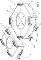
Figure 6 : A perspective view of two embodiments of the claimed tool. -
Figure 7 : Several views of the first embodiment of the claimed tool. -
Figure 8 : Several views of a top plate of the first embodiment. -
Figure 9 : Part of the low-friction intermediate element. -
Figure 10 : Several views of the second embodiment of the tool. -
Figure 11 : Several views of the top plate of the second embodiment. -
Figure 12 : The hydraulic system of the claimed invention. -
Figure 1 illustrates agas turbine 1 in a perspective view as an example for large machinery that has to be aligned properly before being operated. The use of the claimed tools and method is not limited to the alignment of gas turbine, but can be applied to align any type of large machinery. - The
gas turbine 1 is mounted on twosocles 3. On thesesocles 3 four mounting points 5.1, 5.2, 5.3 and 5.4 are provided. Before being mounted on the mounting points 5.1 to 5.4 thegas turbine 1 has to be precisely aligned. Precisely aligned means that at each of the mounting points 5.1 to 5.3 of thegas turbine 1 has an appropriate position in an axial direction A, a lateral direction L and a vertical direction V. Connecting thegas turbine 1 with thesocles 3 at the mounting points 5.1 to 5.4 must not change this alignment. Aligning thegas turbine 1 has to be executed not only when installing thegas turbine 1 for the first time, but in regular time intervals when thegas turbine 1 is overhauled. - The invention claims tools, a system and a method for adjusting the alignment of a
gas turbine 1 or any other machinery in a more efficient and more precise manner than known from the art. - For aligning
gas turbine 1 relative to the mounting points 5.1 to 5.4 it is obvious, that the jaws and bolts connecting thegas turbine 1 with the mounting points 5.1 to 5.4 have to be released. Further means for aligning thegas turbine 1 in the directions of the axes A, L and V are required. To achieve an optimal alignment with regard to precision and costs, the claimed method uses tools for alignment of large machinery at three alignment points AP1, AP2 and AP3. - These three alignment points AP1, AP2 and AP3 are shown schematically in the left part of
figure 1 without the gas turbine. The fact that the claimed method requires only three alignment points AP instead of four alignment points as known from the prior artUS 6,871,412 B2 is a first important advantage with regard to precision and costs of the alignment. - In
figure 1 the alignment movements that are necessary for aligning a gas turbine are illustrated by arrows VR and FR at thealignment point 1, VL and FL at the alignment point 2 and the arrows VA, AK, AA, AL and AF at the alignment point AP3. A similar scheme can be found infigure 12 that shows the hydraulic part of the control unit of the claimed invention. In conjunction with the claimed invention the alignment movements in opposing direction are considered as two alignment movements. For example AL and AR, AA and AF are considered as four alignment movements. FR and FL are considered as two further alignment movements - To properly align the
gas turbine 1 or the other machinery it is obvious that at each alignment point AP1 to AP3 lifting thegas turbine 1 in a vertical direction is required. Consequently, at eachalignment point 1 one alignment movement VR (c.f. API), VL (c.f. AP2) and VA (c.f. AP3 is provided. By means of these three alignment movements VR, VL and VA it is possible to properly align thegas turbine 1 in a vertical direction and to lift thegas turbine 1 from thesocles 3 to allow alignment in a horizontal plane. - To properly align the gas turbine in a lateral direction (parallel to the axis L) four alignment movements FR, FL, AR and AL are required.
- At the alignment point AP1 the alignment movement FR is executed. The same applies to the alignment point AP2 and alignment movement FL. The alignment directions FR and FL have opposite directions. This means that it is sufficient if the tools for aligning a
gas turbine 1 at the alignment points AP1 and AP2 provide one alignment movement. These tools do not require a double-acting actuator or two opposed actuators acting in opposed directions (for example FR and FL). - In other words: The tools for aligning the
gas turbine 1 required in the alignment points AP1 and AP2 are capable only of pushing thegas turbine 1 in the direction of one of the arrows FR and FL. Independent from that it is possible to lift the gas turbine (c.f. the arrows VR and VL) at the alignment points AP1 and AP3 independently from each other. - To complete the alignment of the
gas turbine 1 in a horizontal plane there are four movements required at the alignment point AP3. For a lateral alignment the alignment movements AR and AL (c.f. the arrows AR and AL) are required. - For an axial alignment of the
gas turbine 1 there are two additional alignment movements required (c.f. the arrows AA and AF). - In other words, for perfectly aligning the
gas turbine 1 or any other large machinery at the alignment point AP1 the alignment movements VR and FR, at the alignment point AP2 the alignment movements VL and FL and at the alignment point AP3 five alignment movements VA, AR, AL, AA and AF are required. - For this reason the claimed tool for aligning the gas turbine at the alignment points AP1 and AP2 is simpler and requires less space than the claimed tool required for aligning the
gas turbine 1 at the alignment point AP3. - The alignment of the gas turbine in a vertical direction is executed by means of jacks, preferably by hydraulic jacks, that are known from the art and which are not described in detail.
- In
figure 2 a side view of thegas turbine 1 offigure 1 is illustrated. On the left side of thefigure 2 the alignment point AP1 and the mounting points 5.1 and 5.4 can be seen. - In
figure 2 a side view of thegas turbine 1 offigure 1 is illustrated. On the left side offigure 2 the alignment point AP1 and the mounting point 5.4 can be seen. On the right side offigure 2 the mounting point 5.1 can be seen. The alignment points AP2 and AP3 are not visible infigure 2 . - From
figure 2 it can be seen that the mounting point 5.4 and the alignment point AP1 are nearby or adjacent to each other. The same applies to the mounting point 5.3 and the alignment point AP2 (not visible infigure 2 ). The alignment point AP3 is right in the middle between the mounting points 5.1 and 5.2 as can be seen infigure 3 . -
Figure 3 illustrates a cross-sectional view of thegas turbine 1 along the line A-A fromfigure 2 . In this figure the alignment point AP3 and the mounting points 5.1 and 5.2 can be seen. -
Figure 4 illustrates the detail B fromfigure 3 in a perspective view. Infigure 4 a second embodiment of the claimed tool can be seen. This embodiment of the tool for aligning large machinery has thereference numeral 7. Thetool 7 is capable of executing four alignment movements AR, AA, AL and AF in a horizontal plane as explained in conjunction withfigure 1 . There are four hydraulic inlets 9 illustrated. - On top of tool 7 a
hydraulic jack 11 is arranged havingfurther input 13 to provide an alignment movement VA. -
Figure 5 illustrates the detail C (c.f.figure 1 ) of the first alignment point AP1. The tool for aligning has thereference numeral 15 and is, compared tofigure 4 , mounted upside down. Between thesocle 3 and the tool 15 ahydraulic jack 11 is arranged. Of course, it does not make any difference, whether thehydraulic jack 11 is mounted on top of any of thetools - In
figure 5 it can be seen that between thesocles 3 and the lower part of thegas turbine 1 several mountingbolts 17 andnuts 19 are provided. In case thegas turbine 1 shall be aligned, thenut 19 has to be opened to allow a movement in axial, lateral and vertical direction of thegas turbine 1 relative to thesocle 3 at the mounting point. Thetool 15 provides only one alignment movement and therefore only onehydraulic inlet 13 is provided. - In
figure 6 thetools tools casing - The
tool 7 comprises abase plate 35, a part of which is not covered by thecasing 21. The hydraulic inlets 9FL, 9AR, 9AA and 9AL are mounted on the base plate. Each of these inlets 9 is connected with the respective outlets of a control unit, as illustrated infigure 12 . - The
casing 21 has an opening on its top. Inside this opening 27 atop plate 29 of thetool 7 can be seen. - By means of several hydraulic actuators inside the
casing 21 it is possible to move thetop plate 29 relative to thebase plate 35 in the directions AR, AF, AL and AA. These movements allow the alignment of the third alignment point AP3 as described in conjunction withfigure 1 . - The
tool 15 is based on the same technology as thetool 7, but with a reduced functionality. Thecasing 23 of thetool 15 covers the base plate completely the latter being not visible infigure 6 . Thetop plate 33 of thetool 15 can be seen, since thecasing 23 of thetool 15 provides anopening 36 similar to theopening 27 of thecasing 21. Thetop plate 33 can be moved along the direction illustrated by the arrow FL, FR infigure 6 . Dependent, whether thetool 15 is mounted at the alignment point AP1 or the alignment point AP2, thetool 15 executes the alignment movements FR or FL. In other words: Thetools 15 used at the alignment points AP1 and AP2 are identical, which helps to reduce the costs and increases the availability. - In
figure 7 thetool 15 is shown in several views. In some of these views thecasing 23 has been cut off to show the design details of thetool 15. - In the center of
figure 7 a top view of thetool 15 is shown. At the right side offigure 7 a cross-sectional view along the line BU-BU can be seen. In this cross-sectional view thebase plate 35 and thetop plate 33 are visible. - In the middle of the base plate 35 a projecting
part 37 is provided. It further can be seen that thetop plate 33 comprises arecess 39. The inner diameter of therecess 39 is larger than the outer diameter of the projectingpart 37, such that a relative movement of thetop plate 33 relative to the base plate is possible within the limit set by the difference of the inner diameter of therecess 39 and the outer diameter of the projectingpart 37. - Between the projecting
part 37 and the top plate a low-frictionintermediate element 41 is provided. The low-frictionintermediate element 41 may comprise a plurality of captured ball bearings or comprise two layers of roller bearings at right angles and separated by a plate. This element can also comprise a plate of a low-friction material, such as PTFE (Teflon) or a layer of grease or oil between the recess and the projecting part of thebase plate 33. - On the left side of
figure 7 a top view of thetool 15 is shown, with most of thecasing 23 cut away. From this view it can be seen that thetop plate 33 comprises twolever arms 43, one on each side of thetop plate 33. In this embodiment both lever arms share the same longitudinal axis (not illustrated). Each of thelever arms 43 is connected with apiston 45 of ahydraulic actuator 47. Thetools 15 may be applied in the alignment points AP1 and AP2. - If hydraulic pressure is applied to the
hydraulic actuators 47 thepistons 45 move thelever arms 43 and thetop plate 3 relative to thebase plate 35 executing the desired alignment movement FL, FR. - The
actuators 47 are connected with a control unit (not shown infigure 6 ) and receive hydraulic fluid under pressure, if an alignment movement FR, FL is to be carried out. In the cross-sectional view along the line BU-BU thepistons 45 and thehydraulic actuators 47 can be seen, too. - To center the
top plate 33 relative to thebase plate 35 in case thehydraulic actuators 47 are not pressurized, foursprings 49 are arranged radially between thetop plate 33 and thebase plate 35. -
Figure 8 illustrates thetop plate 33 and itslever arms 43 and itsrecess 39 in more detail. In this exemplary embodiment therecess 39 is circular. Consequently, the projectingpart 37 of the base plate is circular, too. It would also be possible that therecess 39 and the projecting part have a rectangular cross-section. - In
figure 9 a part of the low-frictionintermediate element 41 is illustrated. It comprises aplate 48 having the same diameter as the projecting part of thebase plate 35. Theplate 48 is part of a ball bearing and comprises multiple cavities for balls (not shown) that allow a low-friction relative movement between the top plate and the base plate. - Further details of such a ball bearing or as an alternative a low-friction intermediate element with two layers of roller bearings at right angles can be found in
US 6,871,412 B2 . As mentioned before, in some cases it is sufficient to provide a plate of PTFE (Teflon) between the projectingpart 37 and therecess 39 to sufficiently reduce friction betweentop plate 33 andbase plate 35. -
Figure 10 shows thetool 7 in several views. In principle, the design of thetool 7 is similar to the design of thetool 15, as far as the base plate, the projecting part, the top plate and the recess are concerned. For this reason the same parts have the same reference numerals as thetool 15. For reasons of clarity, not in all views of each reference number is drawn. - The main difference between the
tools tool 7 provides four alignment movements, whereas thetool 15 only provides one alignment movement. - In the top view of
figure 10 the different alignment movements are illustrated similar tofigure 6 . Since thetop plate 33 of thetool 7 shall be moved into four directions AF, AL, AA and AR, there are two pairs oflever arms top plate 33. Thelever arms - At each
lever arm hydraulic actuators 47 are attached. In the top view offigure 10 onelever arm 43, onelever arm 51 and fouractuators 47 are visible, since thecasing 21 is cut away only in part. The other four hydraulic actuators are covered by thecasing 21. Fromfigure 11 details of thetop plate 33 with fourlever arms - In the side view and the top view of
figure 10 the hydraulic inlets 9 can be seen. Each hydraulic inlet 9 is attached to twohydraulic actuators 47, which are parallel to each other and act in the same direction. - E.g., the actuator 47.1 is connected with the inlet 9AL, since the hydraulic actuator 47.1 moves the
top plate 33 towards the direction of the alignment movement AL. The hydraulic actuator 47.2 is connected with the inlet 9AR. The same applies mutatis mutandis to the hydraulic actuators 47.3 and 47.4. By pressurizing e.g. the inlet 9AF and the inlet 9AL it is possible to move thetop plate 33 simultaneously towards the alignment directions AF and AL. It also possible to pressurize the differenthydraulic actuators 7 sequentially, such that the alignment movements towards one of the four directions AA, AR, AF and AL are executed one behind the other. - As has been mentioned before in
figure 10 , only half of theactuators 47 are visible. The respective co-actuators are not visible due to thecasing 21. - From
figure 11 which shows thetop plate 33 in more detail, it becomes clear that thetop plate 33 has a symmetric contour and eighthydraulic actuators 47 can be attached to the fourlevers - Similarly to the
tool 15 foursprings 49 are provided between thetop plate 33 and thebase plate 35 centering thetop plate 33 relatively to thebase plate 35, if none of thehydraulic actuators 47 is pressurized. - In
figure 11 it can be seen that the four noses orprotrusions 53 serve as anchoring points for the springs 49 (not shown infigure11 ). - The
hydraulic jacks 11 and thetools figure 12 . - The control unit comprises a
pump 55 driven by anelectric motor 57 and several hydraulic pipes and valves. Further, the control unit comprises multiple outlets AR, AA, AL, VR, VA, VL, FR, AF and FL. Each of these outlets is connected with one of the hydraulic inlets of thehydraulic jacks 11 or thetools figure 12 and described in detail infigure 1 are executed if the respective outlet of the control unit is pressurized by means of thepump 55 and due to an appropriate command of the valves of the control unit. - The electric parts of the control unit such as a display, a user interface and the wiring for submitting commands to the pump and the valves are not shown.
-
- 1 Gas turbine
- 3 socle
- 5.1 - 5.4 Mounting point
- AP1, AP2, AP3 Alignment point
- VR, FR Alignment Movements at AP1
- VL, FL Alignment Movements at AP2
- VA, AR, AA, AL, AF Alignment Movements at AP3
- 7 Tool
- 9 hydraulic inlet
- 11 hydraulic jack
- 13 hydraulic inlet
- 15 Tool
- 17 mounting bolt
- 19 Nut
- 21, 23 casing
- 25 -
- 27 Opening of the casing
- 29 top plate
- 31 plate
- 33 top plate
- 35 base plate
- 36 opening
- 37 projecting part
- 39 recess
- 41 low friction intermediate element
- 43 lever arm
- 45 piston
- 47 hydraulic actuator
- 48 plate
- 49 spring
- 51 lever arm
- 53 protrusion (nose)
- 55 hydraulic pump
- 57 electric motor
Claims (15)
- Tool for alignment adjustment s of machinery comprising
a bottom plate (35),
a top plate (33), being oriented in parallel planes
a low friction intermediate element (41) between bottom plate (35) and top plate (33),
characterized in, that
it comprises at least one hydraulic actuator (47) or electro-mechanic actuator arranged between the bottom plate (35) and the top plate (33) capable of moving the top plate (33) relative to the bottom plate (35). - Tool according to claim 1, characterized in that the bottom plate (35) comprises a projecting part (37) bearing the low friction intermediate element (41) and in that the top plate (33) comprises a recess (39) surrounding the low friction intermediate element (41) and the projecting part (37).
- Tool according to claim 1 or 2, characterized in that the top plate (33) comprises at least one lever arm (43, 51), that a movable end of the at least one actuator (47) is attached to the at least one lever arm (43, 51) and in that a fixed end of the at least one actuator (47) is attached to the bottom plate (35).
- Tool according to claim 3, characterized in that the top plate (3) comprises a first pair of lever arms (43) and a first pair of actuators (47), that the lever arms (43) of the first pair of lever arms (43) are located on opposite sides of the top plate (33), and in that the actuators (47) of the first pair of actuators are arranged on opposite sides of the top plate (33) and parallel to each other.
- Tool according to claim 3 and 4, characterized in that the top plate (33) comprises a second pair of lever arms (51) and four pairs of actuators (47), that the lever arms (51) of the second pair of lever arms are located on opposite sides of the top plate (33), in that at each lever arm (43, 51) two actuators (47) are mounted on opposite sides of the lever arm (43, 51), and in that the longitudinal axis of the lever arm (43, 51) enclose an angle of 90°.
- Tool according to any one of the preceding claims, characterized in that it comprises lifting means (19) below the bottom plate (35) or on top of the top plate (33)
- Tool according to any one of the preceding claims, characterized in that the actuators (47) are double-acting.
- Tool according to any one of the preceding claims, characterized in that it comprises means for detecting the position of the top plate (33) relative to the bottom plate (35) in at least one direction, preferably in two directions being orthogonal to each other.
- System for alignment adjustment s of large machinery comprising at least two tools (7, 15) according to any one of the preceding claims and a control unit, the tools (7, 17) being connected to the control unit such that each actuator (47) of the tools (7, 15) is driven by the control unit
- System according to claim 9, characterized in that the control unit () controls the actuators (47) by means of a feed forward control or a closed loop control.
- System according to claim 9 or 10, characterized in that the control unit () comprises at least one outlet (VR, FR, VL, FL, VA, AR, AA, AL, AF) for each actuator (47) of each tool (7, 15, 19), a power supply (55, 57), valves or switches for each out let (VR, FR, VL, FL, VA, AR, AA, AL, AF) that are controlled by a processor
- System according to any one of the preceding claims 9 to 11, characterized in that it receives output signals from the means for detecting the position of the top plate (33) relative to the bottom plate (35) from at least one tool (7, 15, 19).
- Method for adjusting the alignment of machinery making use of a system according to claims 9 to 12, comprising the steps of:Elevating the machinery on at least three alignment points (API, AP2, AP3) distal from each other with the lifting means (19),Moving the top plates (33) of each of the tools (7, 15) in an axial and/or lateral direction of the machinery by driving the actuators (47) of the tools (7, 15) until the machinery is aligned properly within the set limits.
- Method according to claim 13, characterized in that the actuators (47) of the tools (7, 15) are driven simultaneously or sequentially.
- Method according to claim 13 or 14, characterized in that before lifting the machinery the misalignment at each alignment point (API, AP2, AP3) is determined and compiled into appropriate driving commands of the control unit
Priority Applications (3)
| Application Number | Priority Date | Filing Date | Title |
|---|---|---|---|
| PL18461517.7T PL3527323T3 (en) | 2018-02-19 | 2018-02-19 | Alignment tool and method for aligning heavy machinery and equipment |
| EP18461517.7A EP3527323B1 (en) | 2018-02-19 | 2018-02-19 | Alignment tool and method for aligning heavy machinery and equipment |
| US16/246,783 US11331760B2 (en) | 2018-02-19 | 2019-01-14 | Alignment tool and method for aligning heavy machinery and equipment |
Applications Claiming Priority (1)
| Application Number | Priority Date | Filing Date | Title |
|---|---|---|---|
| EP18461517.7A EP3527323B1 (en) | 2018-02-19 | 2018-02-19 | Alignment tool and method for aligning heavy machinery and equipment |
Publications (2)
| Publication Number | Publication Date |
|---|---|
| EP3527323A1 true EP3527323A1 (en) | 2019-08-21 |
| EP3527323B1 EP3527323B1 (en) | 2022-06-08 |
Family
ID=61249591
Family Applications (1)
| Application Number | Title | Priority Date | Filing Date |
|---|---|---|---|
| EP18461517.7A Active EP3527323B1 (en) | 2018-02-19 | 2018-02-19 | Alignment tool and method for aligning heavy machinery and equipment |
Country Status (3)
| Country | Link |
|---|---|
| US (1) | US11331760B2 (en) |
| EP (1) | EP3527323B1 (en) |
| PL (1) | PL3527323T3 (en) |
Citations (5)
| Publication number | Priority date | Publication date | Assignee | Title |
|---|---|---|---|---|
| US3849857A (en) * | 1973-07-05 | 1974-11-26 | M Murray | Machine element alignment positioner |
| WO2000056638A1 (en) * | 1999-03-23 | 2000-09-28 | Helge Funch | A lifting jack for handling heavy objects |
| FR2846313A1 (en) * | 2002-10-29 | 2004-04-30 | Savoisienne Des Verins Hydraul | Device for displacing heavy railway equipment comprises pressurized fluid lifting actuator able to be slid in direction perpendicular to lifting axis by motor and non-reversible transmission |
| US6871412B2 (en) | 2002-04-23 | 2005-03-29 | Daniel Markeson | Alignment tool and method for aligning large machinery |
| EP3211187A1 (en) * | 2016-02-29 | 2017-08-30 | General Electric Company | Positioning system for aligning industrial machine coupling elements |
Family Cites Families (2)
| Publication number | Priority date | Publication date | Assignee | Title |
|---|---|---|---|---|
| NL8601095A (en) * | 1986-04-29 | 1987-11-16 | Philips Nv | POSITIONING DEVICE. |
| JP5026455B2 (en) * | 2009-03-18 | 2012-09-12 | 住友重機械工業株式会社 | XY stage apparatus, semiconductor inspection apparatus, and semiconductor exposure apparatus |
-
2018
- 2018-02-19 EP EP18461517.7A patent/EP3527323B1/en active Active
- 2018-02-19 PL PL18461517.7T patent/PL3527323T3/en unknown
-
2019
- 2019-01-14 US US16/246,783 patent/US11331760B2/en active Active
Patent Citations (5)
| Publication number | Priority date | Publication date | Assignee | Title |
|---|---|---|---|---|
| US3849857A (en) * | 1973-07-05 | 1974-11-26 | M Murray | Machine element alignment positioner |
| WO2000056638A1 (en) * | 1999-03-23 | 2000-09-28 | Helge Funch | A lifting jack for handling heavy objects |
| US6871412B2 (en) | 2002-04-23 | 2005-03-29 | Daniel Markeson | Alignment tool and method for aligning large machinery |
| FR2846313A1 (en) * | 2002-10-29 | 2004-04-30 | Savoisienne Des Verins Hydraul | Device for displacing heavy railway equipment comprises pressurized fluid lifting actuator able to be slid in direction perpendicular to lifting axis by motor and non-reversible transmission |
| EP3211187A1 (en) * | 2016-02-29 | 2017-08-30 | General Electric Company | Positioning system for aligning industrial machine coupling elements |
Also Published As
| Publication number | Publication date |
|---|---|
| US20200189049A1 (en) | 2020-06-18 |
| PL3527323T3 (en) | 2022-07-25 |
| US11331760B2 (en) | 2022-05-17 |
| EP3527323B1 (en) | 2022-06-08 |
Similar Documents
| Publication | Publication Date | Title |
|---|---|---|
| EP3211187B1 (en) | Positioning system for aligning industrial machine coupling elements | |
| US20190389704A1 (en) | Independent drive motors for machinery positioning apparatus having independent lifting motors | |
| US9259772B2 (en) | Forming apparatus | |
| CN104907608B (en) | Drilling jig for drilling of outer wallboard of forklift | |
| US20180155160A1 (en) | Crane system and an associated method thereof | |
| US11331760B2 (en) | Alignment tool and method for aligning heavy machinery and equipment | |
| CN102252163A (en) | Automatic loading and unloading machine of cylinder valve | |
| US3604683A (en) | Jacking mechanisms | |
| CN110202545A (en) | A kind of auxiliary drive unit and the six-degree-of-freedom parallel connection mechanism containing the unit | |
| EP2672079A2 (en) | Method and apparatus for roll-in and alignment of a casing shell of a gas turbine | |
| EP1252943A1 (en) | Radial press for fitting hose fittings | |
| CN107651614A (en) | The level height method of adjustment of line pipe joint | |
| CN111591923A (en) | Alignment tool and method for aligning heavy machinery and equipment | |
| EP4157711B1 (en) | Alignment system | |
| CN102182188B (en) | Full hydraulic static pulling machine and method of underground diaphragm wall joint pipe | |
| KR20190142513A (en) | Multiaxial test apparatus for battery crush and penetration test | |
| CN107442635B (en) | Multi-station hydraulic machine hydraulic cushion multifunctional composite hydraulic system | |
| CN110814692A (en) | Multi-degree-of-freedom docking tool for engine separation test and assembling method | |
| CN111120439A (en) | Hydraulic jacking system and operation method thereof | |
| KR200434407Y1 (en) | Block Maintenance Apparatus for Power Plant | |
| CN218377112U (en) | Large-scale derrick deviation rectifying multipoint synchronous electro-hydraulic control system based on variable frequency speed regulation-high speed switch | |
| CN209833965U (en) | Underwater hydraulic control magnetic adsorption walking operation device | |
| CN110756643B (en) | A split type stamping equipment for linear guide production | |
| CN107042318A (en) | A kind of vertical type turning center workpiece jacking mechanism | |
| CN104411451A (en) | Tool for banding mechanical components and banding method using such a tool |
Legal Events
| Date | Code | Title | Description |
|---|---|---|---|
| PUAI | Public reference made under article 153(3) epc to a published international application that has entered the european phase |
Free format text: ORIGINAL CODE: 0009012 |
|
| STAA | Information on the status of an ep patent application or granted ep patent |
Free format text: STATUS: THE APPLICATION HAS BEEN PUBLISHED |
|
| AK | Designated contracting states |
Kind code of ref document: A1 Designated state(s): AL AT BE BG CH CY CZ DE DK EE ES FI FR GB GR HR HU IE IS IT LI LT LU LV MC MK MT NL NO PL PT RO RS SE SI SK SM TR |
|
| AX | Request for extension of the european patent |
Extension state: BA ME |
|
| STAA | Information on the status of an ep patent application or granted ep patent |
Free format text: STATUS: REQUEST FOR EXAMINATION WAS MADE |
|
| 17P | Request for examination filed |
Effective date: 20200119 |
|
| RBV | Designated contracting states (corrected) |
Designated state(s): AL AT BE BG CH CY CZ DE DK EE ES FI FR GB GR HR HU IE IS IT LI LT LU LV MC MK MT NL NO PL PT RO RS SE SI SK SM TR |
|
| RIC1 | Information provided on ipc code assigned before grant |
Ipc: B66F 7/28 20060101ALI20210915BHEP Ipc: B66F 7/16 20060101ALI20210915BHEP Ipc: F01D 25/28 20060101ALI20210915BHEP Ipc: B23P 19/10 20060101AFI20210915BHEP |
|
| GRAP | Despatch of communication of intention to grant a patent |
Free format text: ORIGINAL CODE: EPIDOSNIGR1 |
|
| STAA | Information on the status of an ep patent application or granted ep patent |
Free format text: STATUS: GRANT OF PATENT IS INTENDED |
|
| INTG | Intention to grant announced |
Effective date: 20211029 |
|
| GRAS | Grant fee paid |
Free format text: ORIGINAL CODE: EPIDOSNIGR3 |
|
| GRAA | (expected) grant |
Free format text: ORIGINAL CODE: 0009210 |
|
| STAA | Information on the status of an ep patent application or granted ep patent |
Free format text: STATUS: THE PATENT HAS BEEN GRANTED |
|
| AK | Designated contracting states |
Kind code of ref document: B1 Designated state(s): AL AT BE BG CH CY CZ DE DK EE ES FI FR GB GR HR HU IE IS IT LI LT LU LV MC MK MT NL NO PL PT RO RS SE SI SK SM TR |
|
| REG | Reference to a national code |
Ref country code: AT Ref legal event code: REF Ref document number: 1496583 Country of ref document: AT Kind code of ref document: T Effective date: 20220615 Ref country code: CH Ref legal event code: EP |
|
| REG | Reference to a national code |
Ref country code: DE Ref legal event code: R096 Ref document number: 602018036450 Country of ref document: DE |
|
| REG | Reference to a national code |
Ref country code: IE Ref legal event code: FG4D |
|
| REG | Reference to a national code |
Ref country code: LT Ref legal event code: MG9D |
|
| REG | Reference to a national code |
Ref country code: NL Ref legal event code: MP Effective date: 20220608 |
|
| PG25 | Lapsed in a contracting state [announced via postgrant information from national office to epo] |
Ref country code: SE Free format text: LAPSE BECAUSE OF FAILURE TO SUBMIT A TRANSLATION OF THE DESCRIPTION OR TO PAY THE FEE WITHIN THE PRESCRIBED TIME-LIMIT Effective date: 20220608 Ref country code: NO Free format text: LAPSE BECAUSE OF FAILURE TO SUBMIT A TRANSLATION OF THE DESCRIPTION OR TO PAY THE FEE WITHIN THE PRESCRIBED TIME-LIMIT Effective date: 20220908 Ref country code: LT Free format text: LAPSE BECAUSE OF FAILURE TO SUBMIT A TRANSLATION OF THE DESCRIPTION OR TO PAY THE FEE WITHIN THE PRESCRIBED TIME-LIMIT Effective date: 20220608 Ref country code: HR Free format text: LAPSE BECAUSE OF FAILURE TO SUBMIT A TRANSLATION OF THE DESCRIPTION OR TO PAY THE FEE WITHIN THE PRESCRIBED TIME-LIMIT Effective date: 20220608 Ref country code: GR Free format text: LAPSE BECAUSE OF FAILURE TO SUBMIT A TRANSLATION OF THE DESCRIPTION OR TO PAY THE FEE WITHIN THE PRESCRIBED TIME-LIMIT Effective date: 20220909 Ref country code: FI Free format text: LAPSE BECAUSE OF FAILURE TO SUBMIT A TRANSLATION OF THE DESCRIPTION OR TO PAY THE FEE WITHIN THE PRESCRIBED TIME-LIMIT Effective date: 20220608 Ref country code: ES Free format text: LAPSE BECAUSE OF FAILURE TO SUBMIT A TRANSLATION OF THE DESCRIPTION OR TO PAY THE FEE WITHIN THE PRESCRIBED TIME-LIMIT Effective date: 20220608 Ref country code: BG Free format text: LAPSE BECAUSE OF FAILURE TO SUBMIT A TRANSLATION OF THE DESCRIPTION OR TO PAY THE FEE WITHIN THE PRESCRIBED TIME-LIMIT Effective date: 20220908 |
|
| REG | Reference to a national code |
Ref country code: AT Ref legal event code: MK05 Ref document number: 1496583 Country of ref document: AT Kind code of ref document: T Effective date: 20220608 |
|
| PG25 | Lapsed in a contracting state [announced via postgrant information from national office to epo] |
Ref country code: RS Free format text: LAPSE BECAUSE OF FAILURE TO SUBMIT A TRANSLATION OF THE DESCRIPTION OR TO PAY THE FEE WITHIN THE PRESCRIBED TIME-LIMIT Effective date: 20220608 Ref country code: LV Free format text: LAPSE BECAUSE OF FAILURE TO SUBMIT A TRANSLATION OF THE DESCRIPTION OR TO PAY THE FEE WITHIN THE PRESCRIBED TIME-LIMIT Effective date: 20220608 |
|
| PG25 | Lapsed in a contracting state [announced via postgrant information from national office to epo] |
Ref country code: NL Free format text: LAPSE BECAUSE OF FAILURE TO SUBMIT A TRANSLATION OF THE DESCRIPTION OR TO PAY THE FEE WITHIN THE PRESCRIBED TIME-LIMIT Effective date: 20220608 |
|
| PG25 | Lapsed in a contracting state [announced via postgrant information from national office to epo] |
Ref country code: SM Free format text: LAPSE BECAUSE OF FAILURE TO SUBMIT A TRANSLATION OF THE DESCRIPTION OR TO PAY THE FEE WITHIN THE PRESCRIBED TIME-LIMIT Effective date: 20220608 Ref country code: SK Free format text: LAPSE BECAUSE OF FAILURE TO SUBMIT A TRANSLATION OF THE DESCRIPTION OR TO PAY THE FEE WITHIN THE PRESCRIBED TIME-LIMIT Effective date: 20220608 Ref country code: RO Free format text: LAPSE BECAUSE OF FAILURE TO SUBMIT A TRANSLATION OF THE DESCRIPTION OR TO PAY THE FEE WITHIN THE PRESCRIBED TIME-LIMIT Effective date: 20220608 Ref country code: PT Free format text: LAPSE BECAUSE OF FAILURE TO SUBMIT A TRANSLATION OF THE DESCRIPTION OR TO PAY THE FEE WITHIN THE PRESCRIBED TIME-LIMIT Effective date: 20221010 Ref country code: EE Free format text: LAPSE BECAUSE OF FAILURE TO SUBMIT A TRANSLATION OF THE DESCRIPTION OR TO PAY THE FEE WITHIN THE PRESCRIBED TIME-LIMIT Effective date: 20220608 Ref country code: CZ Free format text: LAPSE BECAUSE OF FAILURE TO SUBMIT A TRANSLATION OF THE DESCRIPTION OR TO PAY THE FEE WITHIN THE PRESCRIBED TIME-LIMIT Effective date: 20220608 Ref country code: AT Free format text: LAPSE BECAUSE OF FAILURE TO SUBMIT A TRANSLATION OF THE DESCRIPTION OR TO PAY THE FEE WITHIN THE PRESCRIBED TIME-LIMIT Effective date: 20220608 |
|
| PG25 | Lapsed in a contracting state [announced via postgrant information from national office to epo] |
Ref country code: IS Free format text: LAPSE BECAUSE OF FAILURE TO SUBMIT A TRANSLATION OF THE DESCRIPTION OR TO PAY THE FEE WITHIN THE PRESCRIBED TIME-LIMIT Effective date: 20221008 |
|
| REG | Reference to a national code |
Ref country code: DE Ref legal event code: R097 Ref document number: 602018036450 Country of ref document: DE |
|
| PG25 | Lapsed in a contracting state [announced via postgrant information from national office to epo] |
Ref country code: AL Free format text: LAPSE BECAUSE OF FAILURE TO SUBMIT A TRANSLATION OF THE DESCRIPTION OR TO PAY THE FEE WITHIN THE PRESCRIBED TIME-LIMIT Effective date: 20220608 |
|
| PLBE | No opposition filed within time limit |
Free format text: ORIGINAL CODE: 0009261 |
|
| STAA | Information on the status of an ep patent application or granted ep patent |
Free format text: STATUS: NO OPPOSITION FILED WITHIN TIME LIMIT |
|
| PG25 | Lapsed in a contracting state [announced via postgrant information from national office to epo] |
Ref country code: DK Free format text: LAPSE BECAUSE OF FAILURE TO SUBMIT A TRANSLATION OF THE DESCRIPTION OR TO PAY THE FEE WITHIN THE PRESCRIBED TIME-LIMIT Effective date: 20220608 |
|
| PGFP | Annual fee paid to national office [announced via postgrant information from national office to epo] |
Ref country code: FR Payment date: 20230119 Year of fee payment: 6 |
|
| 26N | No opposition filed |
Effective date: 20230310 |
|
| PG25 | Lapsed in a contracting state [announced via postgrant information from national office to epo] |
Ref country code: SI Free format text: LAPSE BECAUSE OF FAILURE TO SUBMIT A TRANSLATION OF THE DESCRIPTION OR TO PAY THE FEE WITHIN THE PRESCRIBED TIME-LIMIT Effective date: 20220608 |
|
| PGFP | Annual fee paid to national office [announced via postgrant information from national office to epo] |
Ref country code: PL Payment date: 20230120 Year of fee payment: 6 Ref country code: IT Payment date: 20230120 Year of fee payment: 6 Ref country code: DE Payment date: 20230119 Year of fee payment: 6 |
|
| PG25 | Lapsed in a contracting state [announced via postgrant information from national office to epo] |
Ref country code: MC Free format text: LAPSE BECAUSE OF FAILURE TO SUBMIT A TRANSLATION OF THE DESCRIPTION OR TO PAY THE FEE WITHIN THE PRESCRIBED TIME-LIMIT Effective date: 20220608 |
|
| REG | Reference to a national code |
Ref country code: CH Ref legal event code: PL |
|
| REG | Reference to a national code |
Ref country code: BE Ref legal event code: MM Effective date: 20230228 |
|
| GBPC | Gb: european patent ceased through non-payment of renewal fee |
Effective date: 20230219 |
|
| PG25 | Lapsed in a contracting state [announced via postgrant information from national office to epo] |
Ref country code: LU Free format text: LAPSE BECAUSE OF NON-PAYMENT OF DUE FEES Effective date: 20230219 Ref country code: LI Free format text: LAPSE BECAUSE OF NON-PAYMENT OF DUE FEES Effective date: 20230228 Ref country code: CH Free format text: LAPSE BECAUSE OF NON-PAYMENT OF DUE FEES Effective date: 20230228 |
|
| REG | Reference to a national code |
Ref country code: DE Ref legal event code: R081 Ref document number: 602018036450 Country of ref document: DE Owner name: GENERAL ELECTRIC TECHNOLOGY GMBH, CH Free format text: FORMER OWNER: GENERAL ELECTRIC COMPANY, SCHENECTADY, NY, US |
|
| REG | Reference to a national code |
Ref country code: IE Ref legal event code: MM4A |
|
| PG25 | Lapsed in a contracting state [announced via postgrant information from national office to epo] |
Ref country code: GB Free format text: LAPSE BECAUSE OF NON-PAYMENT OF DUE FEES Effective date: 20230219 |
|
| PG25 | Lapsed in a contracting state [announced via postgrant information from national office to epo] |
Ref country code: IE Free format text: LAPSE BECAUSE OF NON-PAYMENT OF DUE FEES Effective date: 20230219 Ref country code: GB Free format text: LAPSE BECAUSE OF NON-PAYMENT OF DUE FEES Effective date: 20230219 |
|
| PG25 | Lapsed in a contracting state [announced via postgrant information from national office to epo] |
Ref country code: BE Free format text: LAPSE BECAUSE OF NON-PAYMENT OF DUE FEES Effective date: 20230228 |
|
| PGFP | Annual fee paid to national office [announced via postgrant information from national office to epo] |
Ref country code: DE Payment date: 20240123 Year of fee payment: 7 |