EP3527240A1 - Infusion device - Google Patents
Infusion device Download PDFInfo
- Publication number
- EP3527240A1 EP3527240A1 EP17861721.3A EP17861721A EP3527240A1 EP 3527240 A1 EP3527240 A1 EP 3527240A1 EP 17861721 A EP17861721 A EP 17861721A EP 3527240 A1 EP3527240 A1 EP 3527240A1
- Authority
- EP
- European Patent Office
- Prior art keywords
- sub
- liquid
- flow path
- open
- close valve
- Prior art date
- Legal status (The legal status is an assumption and is not a legal conclusion. Google has not performed a legal analysis and makes no representation as to the accuracy of the status listed.)
- Granted
Links
Images



Classifications
-
- A—HUMAN NECESSITIES
- A61—MEDICAL OR VETERINARY SCIENCE; HYGIENE
- A61M—DEVICES FOR INTRODUCING MEDIA INTO, OR ONTO, THE BODY; DEVICES FOR TRANSDUCING BODY MEDIA OR FOR TAKING MEDIA FROM THE BODY; DEVICES FOR PRODUCING OR ENDING SLEEP OR STUPOR
- A61M5/00—Devices for bringing media into the body in a subcutaneous, intra-vascular or intramuscular way; Accessories therefor, e.g. filling or cleaning devices, arm-rests
- A61M5/14—Infusion devices, e.g. infusing by gravity; Blood infusion; Accessories therefor
- A61M5/168—Means for controlling media flow to the body or for metering media to the body, e.g. drip meters, counters ; Monitoring media flow to the body
- A61M5/16804—Flow controllers
- A61M5/16813—Flow controllers by controlling the degree of opening of the flow line
-
- A—HUMAN NECESSITIES
- A61—MEDICAL OR VETERINARY SCIENCE; HYGIENE
- A61M—DEVICES FOR INTRODUCING MEDIA INTO, OR ONTO, THE BODY; DEVICES FOR TRANSDUCING BODY MEDIA OR FOR TAKING MEDIA FROM THE BODY; DEVICES FOR PRODUCING OR ENDING SLEEP OR STUPOR
- A61M5/00—Devices for bringing media into the body in a subcutaneous, intra-vascular or intramuscular way; Accessories therefor, e.g. filling or cleaning devices, arm-rests
- A61M5/14—Infusion devices, e.g. infusing by gravity; Blood infusion; Accessories therefor
-
- A—HUMAN NECESSITIES
- A61—MEDICAL OR VETERINARY SCIENCE; HYGIENE
- A61M—DEVICES FOR INTRODUCING MEDIA INTO, OR ONTO, THE BODY; DEVICES FOR TRANSDUCING BODY MEDIA OR FOR TAKING MEDIA FROM THE BODY; DEVICES FOR PRODUCING OR ENDING SLEEP OR STUPOR
- A61M5/00—Devices for bringing media into the body in a subcutaneous, intra-vascular or intramuscular way; Accessories therefor, e.g. filling or cleaning devices, arm-rests
- A61M5/14—Infusion devices, e.g. infusing by gravity; Blood infusion; Accessories therefor
- A61M5/1407—Infusion of two or more substances
- A61M5/1408—Infusion of two or more substances in parallel, e.g. manifolds, sequencing valves
-
- A—HUMAN NECESSITIES
- A61—MEDICAL OR VETERINARY SCIENCE; HYGIENE
- A61M—DEVICES FOR INTRODUCING MEDIA INTO, OR ONTO, THE BODY; DEVICES FOR TRANSDUCING BODY MEDIA OR FOR TAKING MEDIA FROM THE BODY; DEVICES FOR PRODUCING OR ENDING SLEEP OR STUPOR
- A61M5/00—Devices for bringing media into the body in a subcutaneous, intra-vascular or intramuscular way; Accessories therefor, e.g. filling or cleaning devices, arm-rests
- A61M5/14—Infusion devices, e.g. infusing by gravity; Blood infusion; Accessories therefor
- A61M5/168—Means for controlling media flow to the body or for metering media to the body, e.g. drip meters, counters ; Monitoring media flow to the body
-
- A—HUMAN NECESSITIES
- A61—MEDICAL OR VETERINARY SCIENCE; HYGIENE
- A61M—DEVICES FOR INTRODUCING MEDIA INTO, OR ONTO, THE BODY; DEVICES FOR TRANSDUCING BODY MEDIA OR FOR TAKING MEDIA FROM THE BODY; DEVICES FOR PRODUCING OR ENDING SLEEP OR STUPOR
- A61M5/00—Devices for bringing media into the body in a subcutaneous, intra-vascular or intramuscular way; Accessories therefor, e.g. filling or cleaning devices, arm-rests
- A61M5/14—Infusion devices, e.g. infusing by gravity; Blood infusion; Accessories therefor
- A61M5/168—Means for controlling media flow to the body or for metering media to the body, e.g. drip meters, counters ; Monitoring media flow to the body
- A61M5/16877—Adjusting flow; Devices for setting a flow rate
- A61M5/16881—Regulating valves
-
- A—HUMAN NECESSITIES
- A61—MEDICAL OR VETERINARY SCIENCE; HYGIENE
- A61M—DEVICES FOR INTRODUCING MEDIA INTO, OR ONTO, THE BODY; DEVICES FOR TRANSDUCING BODY MEDIA OR FOR TAKING MEDIA FROM THE BODY; DEVICES FOR PRODUCING OR ENDING SLEEP OR STUPOR
- A61M5/00—Devices for bringing media into the body in a subcutaneous, intra-vascular or intramuscular way; Accessories therefor, e.g. filling or cleaning devices, arm-rests
- A61M5/14—Infusion devices, e.g. infusing by gravity; Blood infusion; Accessories therefor
- A61M5/168—Means for controlling media flow to the body or for metering media to the body, e.g. drip meters, counters ; Monitoring media flow to the body
- A61M5/16886—Means for controlling media flow to the body or for metering media to the body, e.g. drip meters, counters ; Monitoring media flow to the body for measuring fluid flow rate, i.e. flowmeters
- A61M5/1689—Drip counters
-
- A—HUMAN NECESSITIES
- A61—MEDICAL OR VETERINARY SCIENCE; HYGIENE
- A61M—DEVICES FOR INTRODUCING MEDIA INTO, OR ONTO, THE BODY; DEVICES FOR TRANSDUCING BODY MEDIA OR FOR TAKING MEDIA FROM THE BODY; DEVICES FOR PRODUCING OR ENDING SLEEP OR STUPOR
- A61M5/00—Devices for bringing media into the body in a subcutaneous, intra-vascular or intramuscular way; Accessories therefor, e.g. filling or cleaning devices, arm-rests
- A61M5/14—Infusion devices, e.g. infusing by gravity; Blood infusion; Accessories therefor
- A61M5/168—Means for controlling media flow to the body or for metering media to the body, e.g. drip meters, counters ; Monitoring media flow to the body
- A61M5/172—Means for controlling media flow to the body or for metering media to the body, e.g. drip meters, counters ; Monitoring media flow to the body electrical or electronic
-
- A—HUMAN NECESSITIES
- A61—MEDICAL OR VETERINARY SCIENCE; HYGIENE
- A61M—DEVICES FOR INTRODUCING MEDIA INTO, OR ONTO, THE BODY; DEVICES FOR TRANSDUCING BODY MEDIA OR FOR TAKING MEDIA FROM THE BODY; DEVICES FOR PRODUCING OR ENDING SLEEP OR STUPOR
- A61M5/00—Devices for bringing media into the body in a subcutaneous, intra-vascular or intramuscular way; Accessories therefor, e.g. filling or cleaning devices, arm-rests
- A61M5/36—Devices for bringing media into the body in a subcutaneous, intra-vascular or intramuscular way; Accessories therefor, e.g. filling or cleaning devices, arm-rests with means for eliminating or preventing injection or infusion of air into body
Definitions
- the present invention relates to an infusion apparatus to be used to administer a liquid such as a medical solution via a patient's vein.
- infusion to administer medicines, nutrients, electrolytes, or the like via a patient's vein is widely performed.
- an anti-cancer agent it is necessary to administer, to a patient, not only a medical solution that contains the anti-cancer agent but also a plurality of liquids, such as a premedication and a physiological saline for washing out flow paths.
- the plurality of liquids are stored separately in a plurality of respective infusion bags.
- An infusion set that includes a main line and a plurality of sub-injection lines is used to bring a plurality of infusion bags into communication with a needle that has been inserted into a patient's vein (e.g. see Patent Document 1).
- priming an operation, which is called priming, to replace air that is within a flow path in the infusion set with a priming solution (e.g. a physiological saline) needs to be performed.
- a priming solution e.g. a physiological saline
- the infusion bag needs to be sequentially switched to administer liquids in the plurality of infusion bags to a patient in a predetermined order.
- the flow rate of liquid differs depending on the type of liquid, the flow rate needs to be set appropriately every time the infusion bag is switched.
- These operations are usually performed manually by a nurse. From the start to end of infusion, a nurse is called by a nurse call system every time the liquid in each infusion bag runs out, placing a large work load on a nurse.
- a nurse will make an operation error of incorrectly setting the order in which infusion bags are to be switched or the flow rate. Such an operation error may lead to a critical medical accident.
- Patent Document 2 describes an infusion pump that automatically switches between the plurality of infusion bags and sets the flow rate. However, in Patent Document 2, no consideration is given to priming.
- the present invention aims to lighten the burden on an operator, reduce operation errors, and enables accurate and safe infusion by automating priming, switching between containers in which liquids are stored, and setting of the flow rate when administering a plurality of liquids to a patient.
- a first infusion apparatus includes an infusion set and a controller.
- the infusion set includes: a first flow path having a first connector, which is to be connected to a first container for storing a first liquid, at one end, and a downstream connector at the other end; a first open/close valve, a first liquid surface sensor, a second liquid surface sensor, a drip chamber, and a variable valve that are provided in this order on the first flow path from the first connector side toward the downstream connector side; a droplet sensor that the drip chamber is provided with; a second flow path having a second connector, which is to be connected to a second container for storing a second liquid, at one end; and a second open/close valve provided on the second flow path.
- the second flow path is in communication with a portion of the first flow path between the first liquid surface sensor and the second liquid surface sensor.
- the controller is configured to control the first open/close valve, the variable valve, and the second open/close valve based on signals from the first liquid surface sensor, the second liquid surface sensor, and the droplet sensor.
- a second infusion apparatus includes an infusion set and a controller.
- the infusion set includes: a first flow path having a first connector, which is to be connected to a first container for storing a first liquid, at one end, and a downstream connector at the other end; a first open/close valve, a drip chamber, and a variable valve that are provided in this order on the first flow path from the first connector side toward the downstream connector side; a droplet sensor, a first liquid surface sensor, and a second liquid surface sensor that the drip chamber is provided with in this order from an upper side toward a lower side; an air discharge tube that is in communication with a gas storing portion in the drip chamber; an air discharge tube open/close valve that the air discharge tube is provided with; a second flow path having a second connector, which is to be connected to a second container for storing a second liquid, at one end; and a second open/close valve provided on the second flow path.
- the second flow path is in communication with a portion of the first flow path between the first open/close valve and the drip chamber.
- the controller is configured to control the first open/close valve, the variable valve, the second open/close valve, and the air discharge tube open/close valve based on signals from the droplet sensor, the first liquid surface sensor, and the second liquid surface sensor.
- the first and second infusion apparatuses according to the present invention make it possible to automatically switch from the first container to the second container and set the flow rate of the first liquid and the second liquid, after a drip of the first liquid has been started. Also, the side-injection line (the second flow path) can be automatically primed immediately before a drip of the second liquid is given. Accordingly, the infusion apparatus according to the present invention is advantageous in lightening the work load on an operator. In addition, it is less likely that an operation error of incorrectly setting the order in which containers are to be switched or the flow rate occurs, and thus, the infusion apparatus according to the present invention is advantageous in increasing accuracy and safety of infusion.
- the variable valve may be closed and the second open/close valve may be opened to flow the second liquid into the second flow path, and if the first liquid surface sensor detects an interface between air and the second liquid, the first open/close valve may be closed and the variable valve may be opened to flow the second liquid from the second container toward the downstream connector.
- the infusion set may further include: a third flow path having a third connector, which is to be connected to a third container for storing a third liquid, at one end; and a third open/close valve provided on the third flow path.
- the third flow path may be in communication with a portion of the first flow path between the first liquid surface sensor and the second liquid surface sensor.
- the controller may be configured to control the third open/close valve based on a signal from the second liquid surface sensor.
- the third flow path can be automatically primed immediately before a drip of the third liquid is given.
- the second liquid surface sensor detects an interface between the second liquid and air
- the second open/close valve and the variable valve may be closed and the first open/close valve and the third open/close valve may be opened to flow the third liquid into the third flow path
- the first open/close valve may be closed and the variable valve may be opened to flow the third liquid from the third container toward the downstream connector.
- the above-described first infusion apparatus may further include a sub-infusion set.
- the sub-infusion set may include: a first sub-flow path having a first sub-connector, which is to be connected to a first sub-container for storing a first sub-liquid, at one end, the other end being configured to be in communication with a portion of the first flow path on the downstream connector side of the variable valve, or with a flow path that is to be connected to the downstream connector in the infusion set; a first sub-open/close valve, a first sub-liquid surface sensor, a second sub-liquid surface sensor, a sub-drip chamber, and a sub-variable valve that are provided in this order on the first sub-flow path from the first sub-connector side toward the other end side of the first sub-flow path; a sub-droplet sensor that the sub-drip chamber is provided with; a second sub-flow path having a second sub-connector, which is to be connected to a second sub-container for
- the second sub-flow path may be in communication with a portion of the first sub-flow path between the first sub-liquid surface sensor and the second sub-liquid surface sensor.
- the controller may be configured to control the first sub-open/close valve, the sub-variable valve, and the second sub-open/close valve based on signals from the first sub-liquid surface sensor, the second sub-liquid surface sensor, and the sub-droplet sensor.
- variable valve in the infusion set and the sub-variable valve in the sub-infusion set may be configured to open simultaneously. According to this configuration, drips of a plurality of liquids can be started simultaneously, and thus, simultaneous drip of the plurality of liquids can be given reliably.
- the air discharge tube may be in communication with a portion of the first flow path on the first connector side of the first open/close valve, or with the first connector.
- the second liquid surface sensor detects that a liquid surface within the drip chamber has reached a lower limit position, in a state where the second open/close valve and the air discharge tube open/close valve are closed and the first open/close valve and the variable valve are opened to flow the first liquid from the first container toward the downstream connector, the first open/close valve and the variable valve may be closed and the second open/close valve and the air discharge tube open/close valve may be opened to flow the second liquid into the second flow path, and if the first liquid surface sensor detects that the liquid surface within the drip chamber has reached an upper limit position, the air discharge tube open/close valve may be closed and the variable valve may be opened to flow the second liquid from the second container toward the downstream connector.
- termination of infusion of the first liquid, priming of the second flow path, and starting of infusion of the second liquid can be automatically performed sequentially.
- the infusion set may further include: a third flow path having a third connector, which is to be connected to a third container for storing a third liquid, at one end; and a third open/close valve provided on the third flow path.
- the third flow path may be in communication with a portion of the first flow path between the first open/close valve and the drip chamber.
- the controller may be configured to control the third open/close valve based on a signal from the second liquid surface sensor.
- the second liquid surface sensor detects that a liquid surface within the drip chamber has reached a lower limit position, in a state where the first open/close valve, the third open/close valve, and the air discharge tube open/close valve are closed and the second open/close valve and the variable valve are opened to flow the second liquid from the second container toward the downstream connector, the second open/close valve and the variable valve may be closed and the third open/close valve and the air discharge tube open/close valve may be opened to flow the third liquid into the third flow path, and if the first liquid surface sensor detects that the liquid surface within the drip chamber has reached an upper limit position, the air discharge tube open/close valve may be closed and the variable valve may be opened to flow the third liquid from the third container toward the downstream connector.
- termination of infusion of the second liquid, priming of the third flow path, and starting of infusion of the third liquid can be automatically performed sequentially.
- the above-described second infusion apparatus may further include a sub-infusion set.
- the sub-infusion set may include: a first sub-flow path having a first sub-connector, which is to be connected to a first sub-container for storing a first sub-liquid, at one end, the other end being configured to be in communication with a portion of the first flow path on the downstream connector side of the variable valve, or with a flow path that is to be connected to the downstream connector in the infusion set; a first sub-open/close valve, a sub-drip chamber, and a sub-variable valve that are provided in this order on the first sub-flow path from the first sub-connector side toward the other end side of the first sub-flow path; a sub-droplet sensor, a first sub-liquid surface sensor, and a second sub-liquid surface sensor that the sub-drip chamber is provided with in this order from an upper side toward a lower side; a sub-air discharge tube that is in communication with a gas storing portion in
- the second sub-flow path may be in communication with a portion of the first sub-flow path between the first sub-open/close valve and the sub-drip chamber.
- the controller may be configured to control the first sub-open/close valve, the sub-variable valve, the second sub-open/close valve, and the sub-air discharge tube open/close valve based on signals from the sub-droplet sensor, the first sub-liquid surface sensor, and the second sub-liquid surface sensor.
- variable valve in the infusion set and the sub-variable valve in the sub-infusion set may be configured to open simultaneously. According to this configuration, drips of a plurality of liquids can be started simultaneously, and thus, simultaneous drip of the plurality of liquids can be given reliably.
- An infusion apparatus includes an infusion set 1 and a controller.
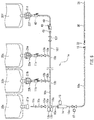
- FIG. 1 shows a schematic configuration of the infusion set 1 (the controller is not shown).
- the infusion set 1 is used to sequentially administer, to a patient, a first liquid to a fifth liquid, which are stored respectively in a first container 20a to a fifth container 20e.
- the first liquid stored in the first container 20a may be a medical solution that contains a premedication
- the second to fourth liquids stored in the second to fourth containers 20b to 20d may be medical solutions that contain an anti-cancer agent
- the fifth liquid stored in the fifth container 20e may be a physiological saline for washing out flow paths.
- the first container 20a to the fifth container 20e are sealed infusion bags, each of which is constituted by two soft sheets that are adhered to each other at their peripheral portions.
- the first container 20a to the fifth container 20e include ports 21a to 21e, respectively, for drawing out the stored liquids. Openings of the ports 21a to 21e are sealed by rubber plugs (which are not visible in FIG. 1 ).
- the infusion set 1 includes a first flow path 10a, which serves as a main line.
- the first flow path 10a is constituted by a hollow, soft tube.
- the first flow path 10a has a first connector 11a and a downstream connector 19 at an upstream end and a downstream end thereof, respectively.
- the first connector 11a and the downstream connector 19 are in communication with each other via the first flow path 10a.
- the first connector 11a is a puncture needle (which may also be called a spike) that has an acute tip, and is inserted into the rubber plug provided in the port 21a of the first container 20a.
- the downstream connector 19 is connected to a connector 32, which is provided at an upstream end of a soft tube 30.
- a needle 31, which is to be inserted into a patient's vein, is provided at a downstream end of the tube 30.
- a first open/close valve 12a, a first liquid surface sensor 13a, a second liquid surface sensor 13b, a drip chamber 14, and a variable valve 17 are provided in this order on the first flow path 10a from the first connector 11a side toward the downstream connector 19 side.
- the first open/close valve 12a is an electric pinch clamp, for example, and opens and closes the first flow path 10a based on a signal from a controller (not shown).
- the first liquid surface sensor 13a and the second liquid surface sensor 13b detect an interface (i.e. liquid surface) between a liquid and air within the first flow path 10a, and output detection signals to the controller.
- the drip chamber 14 makes flowing of a liquid through the first flow path 10a visible.
- the drip chamber 14 is provided with a droplet sensor 15.
- the droplet sensor 15 detects droplets that drip down within the drip chamber 14, and outputs a detection signal to the controller.
- the variable valve 17 is an electric variable pinch clamp, for example, and adjusts the flow rate of a liquid flowing through the first flow path 10a by adjusting the cross-sectional area of the first flow path 10a based on a signal from the controller (not shown).
- the infusion set 1 also includes a second flow path 10b, a third flow path 10c, a fourth flow path 10d, and a fifth flow path 10e, which serve as side-injection lines.
- the second to fifth flow paths 10b to 10e are constituted by hollow, soft tubes, similarly to the first flow path 10a.
- the second, third, fourth, and fifth flow paths 10b, 10c, 10d, and 10e have second, third, fourth, and fifth connectors 11b, 11c, 11d, and 11e, respectively, at their upstream ends.
- the second to fifth connectors 11b to 11e are lever lock connectors each including a male member and a lock lever with a claw (e.g. see Patent Document 3).
- the second to fifth connectors 11b to 11e are connected to the ports 21b to 21e of the second to fifth containers 20b to 20e via adapters 22b to 22e, respectively.
- Each of the adapters 22b to 22e includes a puncture needle, which has an acute tip capable of being inserted into a corresponding one of the rubber plugs in the ports 21b to 21e, an engaging claw, which is to engage with a corresponding one of the ports 21b to 21e, and a mixture injection port, which has an elastic partition member called a septum (e.g. see Patent Document 4).
- the male members of the second to fifth connectors 11b to 11e are inserted into the elastic partition members of the mixture injection ports, and the claws of the second to fifth connectors 11b to 11e engage with the mixture injection ports of the ports 21b to 21e.
- Connecting the second to fifth flow paths 10b to 10e to the ports 21b to 21e via the second to fifth connectors 11b to 11e and the adapters 22b to 22e is advantageous in reducing the likelihood of a hazardous medicine, such as an anti-cancer agent, leaking out to the outside and an operator being exposed to the medicine.
- the second to fifth flow paths 10b to 10e are brought into communication with a portion of the first flow path 10a between the first liquid surface sensor 13a and the second liquid surface sensor 13b.
- one branch flow path 10x branches from a first branching portion 18a, which is provided on the first flow path 10a and has a T-shape (or a Y-shape), second, third, and fourth branching portions 18b, 18c, and 18d, which have a T-shape (or a Y-shape), are provided in this order on the branch flow path 10x, a second flow path 10b branches from the second branching portion 18b, a third flow path 10c branches from the third branching portion 18c, and a fourth flow path 10d and a fifth flow path 10e branch from the fourth branching portion 18d.
- the second to fifth flow paths (side-injection lines) 10b to 10e mean portions from the second to fifth connectors 11b, respectively, to 11e to the first flow path (main line) 10a. Accordingly, in the configuration in FIG. 1 , each of the second to fifth flow paths 10b to 10e has a flow path portion that is shared with the other flow paths, and a unique flow path portion that is distinguished from the other flow paths.
- Second, third, fourth, and fifth open/close valves 12b, 12c, 12d, and 12e are provided on the second, third, fourth, and fifth flow paths 10b, 10c, 10d, and 10e, respectively. If, as shown in FIG. 1 , the second to fifth flow paths 10b to 10e have, as a portion thereof, a shared flow path portion shared by the other flow paths, the second to fifth open/close valves 12b to 12e are provided on the unique flow path portions that are distinguished from the other flow paths.
- the second to fifth open/close valves 12b to 12e are electric pinch clamps, for example, similarly to the first open/close valve 12a, and open and close the second to fifth flow paths 10b to 10e, respectively, based on a signal from the controller (not shown).
- Embodiment 1 A description will now be given of a method of using the infusion apparatus according to Embodiment 1 that is configured as described above. Note that, in Embodiment 1, the first liquid to the fifth liquid flow within the infusion set 1 utilizing gravity, as will be described later, similarly to ordinary infusion.
- the first container 20a to the fifth container 20e, in which the first liquid to the fifth liquid are stored, respectively, are suspended from, for example, an irrigator stand (not shown), with the ports 21a to 21e facing downward.
- the adapters 22b to 22e are attached to the ports 21b to 21e.
- An infusion set 1 with the first to fifth open/close valves 12a to 12e and the variable valve 17 in a closed state is prepared.
- the first connector 11a in the infusion set 1 is connected to the port 21a of the first container 20a, and the second to fifth connectors 11b to 11e in the infusion set 1 are connected to the adapters 22b to 22e, respectively.
- the first flow path 10a is suspended in a substantially vertical direction due to gravity such that the first connector 11a, the first open/close valve 12a, the first liquid surface sensor 13a, the second liquid surface sensor 13b, the drip chamber 14, and the variable valve 17 are arranged in this order from the upper side toward the lower side.
- the second to fifth containers 20b to 20e are arranged at positions higher than the first open/close valve 12a.
- the downstream connector 19 is connected to the connector 32.
- the first flow path 10a is primed using the first liquid (e.g. a premedication) in the first container 20a. That is to say, the first open/close valve 12a and the variable valve 17 are opened.
- the first liquid in the first container 20a flows from the first connector 11a into the first flow path 10a.
- the first open/close valve 12a and/or the variable valve 17 are closed once.
- a flow path that extends from the first container 20a to the needle 31 through the first flow path 10a and the tube 31 is filled with the first liquid.
- the above operation to open and close the first open/close valve 12a and the variable valve 17 that accompanies the priming operation may be automatically performed by the controller, or may be manually performed by an operator.
- the needle 31 is inserted into a patient's vein.
- the controller again opens the first open/close valve 12a and the variable valve 17. A drip of the first liquid is started.
- the flow rate of the first liquid is monitored by the droplet sensor 15.
- the controller adjusts the degree of opening of the variable valve 17 such that the flow rate of the first liquid takes a predetermined value, based on a flow rate signal that is associated with the flow rate and is output from the droplet sensor 15.
- the controller opens the second open/close valve 12b at the same time as or subsequently to closing the variable valve 17.
- the second liquid in the second container 20b flows into the second flow path 10b. Since the variable valve 17 and the third to fifth open/close valves 12c to 12e are closed, as a result of the second liquid flowing into the second flow path 10b, air that was in the second flow path 10b prior to the inflow of the second liquid flows into the first flow path 10a through the first branching portion 18a, and is pushed out toward the first container 20a.
- the interface (liquid surface) between air and the second liquid passes through the first branching portion 18a and moves up within the first flow path 10a.
- the first liquid surface sensor 13a upon detecting the liquid surface, outputs a liquid surface detection signal to the controller.
- the controller closes the first open/close valve 12a and opens the variable valve 17, based on the liquid surface detection signal from the first liquid surface sensor 13a. Thereafter, the second liquid moves down the first flow path 10a through the first branching portion 18a, and flows toward the downstream connector 19. Thus, the drip of the first liquid remaining in the first flow path 10a is resumed, and subsequently, a drip of the second liquid is started.
- the flow rate of the second liquid is monitored by the droplet sensor 15.
- the controller adjusts the degree of opening of the variable valve 17 such that the flow rate of the second liquid takes a predetermined value, based on a flow rate signal that is associated with the flow rate and is output from the droplet sensor 15.
- Air that was in the second flow path 10b before the second open/close valve 12b was opened is confined to a portion of the first flow path 10a on the upstream side (i.e. on the first container 20a side) of the first open/close valve 12a and the first container 20a.
- the controller opens the first open/close valve 12a and the third open/close valve 12c at the same time as or subsequently to closing the second open/close valve 12b and the variable valve 17.
- the third liquid in the third container 20c flows into the third flow path 10c. Since the variable valve 17 and the second, fourth, and fifth open/close valves 12b, 12d, and 12e are closed, as a result of the third liquid flowing into the third flow path 10c, air that was in the third flow path 10c prior to the inflow of the third liquid flows into the first flow path 10a through the first branching portion 18a, and is pushed out toward the first container 20a. The interface (liquid surface) between the air and the third liquid passes through the first branching portion 18a and moves up within the first flow path 10a.
- the first liquid surface sensor 13a upon detecting the liquid surface, outputs a liquid surface detection signal to the controller.
- the controller closes the first open/close valve 12a and opens the variable valve 17 based on this liquid surface detection signal from the first liquid surface sensor 13a.
- the third liquid moves down the first flow path 10a through the first branching portion 18a, and flows toward the downstream connector 19.
- the flow rate of the third liquid is monitored by the droplet sensor 15.
- the controller adjusts the degree of opening of the variable valve 17 such that the flow rate of the third liquid takes a predetermined value, based on a flow rate signal that is associated with the flow rate and is output from the droplet sensor 15. Air that was in the third flow path 10c before the third open/close valve 12c was opened is confined to a portion of the first flow path 10a on the upstream side (i.e. on the first container 20a side) of the first open/close valve 12a and the first container 20a.
- drips of the fourth liquid in the fourth container 20d and the fifth liquid in the fifth container 20e are sequentially given according to a similar procedure. If the droplet sensor 15 detects that the fifth liquid has run out, the controller closes the fifth open/close valve 12e and the variable valve 17. The drips of the first liquid to the fifth liquid thus end.
- the infusion apparatus automatically switches between the first container 20a to the fifth container 20e in which the first liquid to the fifth liquid are stored, respectively, and sets the flow rate of the first to the fifth liquids.
- This configuration is advantageous in lightening the work load on an operator and preventing a human error during operation.
- the infusion apparatus automatically primes the second to fifth flow paths 10b to 10e after a drip of the first liquid has been started and immediately before drips of the second to fifth liquids are given, respectively.
- a method called back-priming which is also called priming-back
- a priming solution is made to flow backward from the main line toward the side-injection lines
- the priming operation for the side-injection lines can be automated. This point is also advantageous in lightening the work load on the operator.
- the side-injection lines (the second to fifth flow paths 10b to 10e) are primed using the respective liquids stored in the containers that are connected to the side-injection lines.
- a hazardous medicine such as an anti-cancer agent
- air that was discharged from the side-injection line due to priming contains vapor of the hazardous medicine.
- air that was in the side-injection line before priming was performed is confined to the portion of the first flow path 10a on the upstream side (i.e. on the first container 20a side) of the first open/close valve 12a and the first container 20a, and does not leak out to the outside. This configuration is advantageous in reducing the likelihood of medicine exposure due to priming.
- the infusion apparatus according to Embodiment 2 includes an infusion set 2 and a controller.
- FIG. 2 shows a schematic configuration of the infusion set 2 (the controller is not shown).
- the infusion set 2 does not include the first liquid surface sensor 13a and the second liquid surface sensor 13b that are included in the infusion set 1 according to Embodiment 1.
- the drip chamber 14 is provided with a first liquid surface sensor 16a and a second liquid surface sensor 16b.
- the infusion set 2 includes an air discharge tube 10g, which bring a gas storing portion of the drip chamber 14 into communication with a portion of the first flow path 10a on the upstream side (i.e. on the first connector 11a side) of the first open/close valve 12a, or with the first connector 11a, and an air discharge tube open/close valve 12g, which is provided on the air discharge tube 10g.
- the first liquid surface sensor 16a and the second liquid surface sensor 16b detect an interface (i.e. liquid surface) between a liquid in the drip chamber 14 and air, and output a detection signal to a controller (not shown).
- the droplet sensor 15, the first liquid surface sensor 16a, and the second liquid surface sensor 16b are arranged in this order on the drip chamber 14 from the upper side toward the lower side.
- the first liquid surface sensor 16a is provided so as to detect an upper limit position of the liquid surface within the drip chamber 14, and the second liquid surface sensor 16b is provided so as to detect a lower limit position of the liquid surface within the drip chamber 14.
- the air discharge tube 10g is not limited, but may be constituted by a hollow, soft tube, similarly to the first to fifth flow paths 10a to 10e.
- the lower end of the air discharge tube 10g is in communication with a portion where air exists above the liquid surface within the drip chamber 14 (the gas storing portion).
- the drip chamber 14 is constituted by a chamber in which a liquid is stored and that is transparent and has a cylindrical shape, and a cap for closing an opening at the upper end of the chamber.
- the lower end of the air discharge tube 10g is connected to the cap.
- the lower end of the air discharge tube 10g may also be connected to the chamber as long as the air discharge tube 10g is in communication with the gas storing portion in the drip chamber 14.
- the air discharge tube 10g brings the gas storing portion in the drip chamber 14 into communication with a portion of the first flow path 10a on the upstream side (i.e. on the first container 20a side) of the first open/close valve 12a, when the first open/close valve 12a is closed.
- the upper end of the air discharge tube 10g is connected to the base end of the first connector 11a, but may alternatively be connected to a portion of the first flow path 10a between the first open/close valve 12a and the first connector 11a.
- the air discharge tube open/close valve 12g is an electric pinch clamp, for example, similarly to the first to fifth open/close valves 12a to 12e, and opens and closes the air discharge tube 10g based on a signal from the controller (not shown).
- the first container 20a to the fifth container 20e, in which the first liquid to the fifth liquid are stored, respectively, are suspended from, for example, an irrigator stand (not shown), with the ports 21a to 21e facing downward.
- the adapters 22b to 22e are attached to the ports 21b to 21e.
- An infusion set 2 with the first to fifth open/close valves 12a to 12e, the air discharge tube open/close valve 12g, and the variable valve 17 in a closed state is prepared.
- the first connector 11a in the infusion set 2 is connected to the port 21a of the first container 20a, and the second to fifth connectors 11b to 11e in the infusion set 2 are connected to the adapters 22b to 22e, respectively.
- the first flow path 10a is suspended in a substantially vertical direction due to gravity such that the first connector 11a, the first open/close valve 12a, the drip chamber 14, and the variable valve 17 are arranged in this order from the upper side toward the lower side.
- the second to fifth containers 20b to 20e are arranged at positions higher than the first open/close valve 12a.
- the downstream connector 19 is connected to the connector 32.
- the first flow path 10a is primed using the first liquid (e.g. a premedication) in the first container 20a. That is to say, the first open/close valve 12a and the variable valve 17 are opened.
- the first liquid in the first container 10a flows from the first connector 20a into the first flow path 11a.
- the first open/close valve 12a and/or the variable valve 17 are closed once.
- a flow path that extends from the first container 20a to the needle 31 through the first flow path 10a and the tube 31 is filled with the first liquid.
- the above operation to open and close the first open/close valve 12a and the variable valve 17 that accompanies the priming operation may be automatically performed by the controller, or may be manually performed by an operator.
- the needle 31 is inserted into a patient's vein.
- the controller again opens the first open/close valve 12a and the variable valve 17.
- a drip of the first liquid is started.
- the flow rate of the first liquid is monitored by the droplet sensor 15, and the liquid surface within the drip chamber 14 is monitored by the first liquid surface sensor 16a and the second liquid surface sensor 16b.
- the controller adjusts the degree of opening of the variable valve 17 such that the flow rate of the first liquid takes a predetermined value, based on a flow rate signal that is associated with the flow rate and is output from the droplet sensor 15.
- the controller may issue an alarm, or may also adjust the degree of opening of the variable valve 17 such that the liquid surface is located in this range.
- the controller opens the second open/close valve 12b and the air discharge tube open/close valve 12g at the same time as or subsequently to closing the first open/close valve 12a and the variable valve 17.
- the second liquid in the second container 20b flows into the second flow path 10b. Since the variable valve 17 and the first and third to fifth open/close valves 12a and 12c to 12e are closed, as a result of the second liquid flowing into the second flow path 10b, air that was in the second flow path 10b prior to the inflow of the second liquid flows into the first flow path 10a, the drip chamber 14, and the air discharge tube 10g, in this order, through the first branching portion 18a, and is pushed out toward the first container 20a.
- the second liquid that has flowed into the second flow path 10b flows into the drip chamber 14 through the first branching portion 18a and the first flow path 10a in this order.
- the liquid surface within the drip chamber 14 rises gradually.
- the first liquid surface sensor 16a upon detecting that the liquid surface has reached the upper limit position, outputs a restored liquid surface signal to the controller.
- the controller closes the air discharge tube open/close valve 12g and opens the variable valve 17, based on the restored liquid surface signal from the first liquid surface sensor 16a.
- the second liquid moves down the first flow path 10a through the first branching portion 18a, and flows toward the downstream connector 19.
- the drip of the first liquid remaining in the first flow path 10a is resumed, and subsequently, a drip of the second liquid is started.
- the flow rate of the second liquid is monitored by the droplet sensor 15, and the liquid surface within the drip chamber 14 is monitored by the first liquid surface sensor 16a and the second liquid surface sensor 16b.
- the controller adjusts the degree of opening of the variable valve 17 such that the flow rate of the second liquid takes a predetermined value, based on a flow rate signal that is associated with the flow rate and is output from the droplet sensor 15. If the liquid surface within the drip chamber 14 is out of the range from the upper limit position (the first liquid surface sensor 16a) to the lower limit position (the second liquid surface sensor 16b), the controller may issue an alarm, or may adjust the degree of opening of the variable valve 17 such that the liquid surface is located in this range. Air that was in the second flow path 10b before the second open/close valve 12b was opened is confined to the gas storing portion in the drip chamber 14, the air discharge tube 10g, and the first container 20a.
- the controller opens the third open/close valve 12c and the air discharge tube open/close valve 12g at the same time as or subsequently to closing the second open/close valve 12b and the variable valve 17.
- the third liquid in the third container 20c flows into the third flow path 10c. Since the variable valve 17 and the first, second, fourth, and fifth open/close valves 12a, 12b, 12d, and 12e are closed, as a result of the third liquid flowing into the third flow path 10c, air that was in the third flow path 10c prior to the inflow of the third liquid flows into the first flow path 10a, the drip chamber 14, and the air discharge tube 10g, in this order, through the first branching portion 18a, and is pushed out toward the first container 20a.
- the third liquid that has flowed into the third flow path 10c flows into the drip chamber 14 through the first branching portion 18a and the first flow path 10a in this order.
- the liquid surface within the drip chamber 14 rises gradually.
- the first liquid surface sensor 16a upon detecting that the liquid surface has reached the upper limit position, outputs a restored liquid surface signal to the controller.
- the controller closes the air discharge tube open/close valve 12g and opens the variable valve 17, based on the restored liquid surface signal from the first liquid surface sensor 16a.
- the third liquid moves down the first flow path 10a through the first branching portion 18a, and flows toward the downstream connector 19.
- the drip of the second liquid remaining in the first flow path 10a is resumed, and subsequently, a drip of the third liquid is started.
- the flow rate of the third liquid is monitored by the droplet sensor 15, and the liquid surface within the drip chamber 14 is monitored by the first liquid surface sensor 16a and the second liquid surface sensor 16b.
- the controller adjusts the degree of opening of the variable valve 17 such that the flow rate of the third liquid takes a predetermined value, based on a flow rate signal that is associated with the flow rate and is output from the droplet sensor 15. If the liquid surface within the drip chamber 14 is out of the range from the upper limit position (the first liquid surface sensor 16a) to the lower limit position (the second liquid surface sensor 16b), the controller may issue an alarm, or may adjust the degree of opening of the variable valve 17 such that the liquid surface is located in this range. Air that was in the third flow path 10c before the third open/close valve 12c was opened is confined to the gas storing portion in the drip chamber 14, the air discharge tube 10g, and the first container 20a.
- drips of the fourth liquid in the fourth container 20d and the fifth liquid in the fifth container 20e are sequentially given according to a similar procedure. If the droplet sensor 15 and the second liquid surface sensor 16b detect that the fifth liquid has run out, the controller closes the fifth open/close valve 12e and the variable valve 17. The drips of the first liquid to the fifth liquid thus end.
- Embodiment 2 As well, after a drip of the first liquid has been started, switching between the first container 20a to the fifth container 20e in which the first liquid to the fifth liquid are stored, respectively, and setting of the flow rate of the first liquid to the fifth liquid are automatically performed.
- This configuration is advantageous in lightening the work load on an operator and preventing a human error in operation.
- the side-injection lines (the second to fifth flow paths 10b to 10e) are automatically primed after a drip of the first liquid has been started and immediately before drips of the second liquid to the fifth liquid are given, respectively. This configuration is also advantageous in reducing the work load on an operator.
- Air that was in the side-injection lines (the second to fifth flow paths 10b to 10e) before the side-injection lines were primed is confined to the drip chamber 14, the air discharge tube 10g, and the first container 20a. As a result, the air does not leak out to the outside, similarly to Embodiment 1.
- This configuration is advantageous in reducing the likelihood of medicine exposure due to priming.
- the upper end of the air discharge tube 10g is connected to the first flow path 10a or the first connector 11a, but the present invention is not limited thereto.
- the air discharge tube 10g may alternatively be connected to a sealed discharged air collection container (bag) that differs from the first to fifth containers 20a to 20e in which liquids are stored. In this case, air that was in the side-injection lines before priming is collected into the discharged air collection container, rather than the first container 10a.
- bag sealed discharged air collection container
- the upper end of the air discharge tube 10g may be open to the outside.
- Embodiment 2 is the same as Embodiment 1, except for the above-described configuration.
- the descriptions of Embodiment 1 are also applied to Embodiment 2.
- the first liquid to the fifth liquid that are stored respectively in the first container 20a to the fifth container 20e are sequentially administered to a patient.
- a plurality of different liquids e.g. two types of anti-cancer agents, or an anti-cancer agent and an enhancer for this anti-cancer agent
- Embodiment 3 of the present invention provides an infusion apparatus that enables such simultaneous administration of a plurality of liquids.
- FIG. 3 shows a schematic configuration of the infusion apparatus according to Embodiment 3 (a controller is not shown).
- the infusion apparatus according to Embodiment 3 includes a sub-infusion set 1' in addition to the infusion set 1 described in Embodiment 1 (see FIG. 1 ), which serves as a main infusion set.
- the sub-infusion set 1' includes the same members as those constituting the infusion set 1, or members corresponding to the members that constitute the infusion set 1. To distinguish the members that constitute the sub-infusion set 1' from the corresponding members of the infusion set 1, sub- is appended to the names of the members that constitute the sub-infusion set 1', and ['] is appended to the reference numerals of these members.
- a first sub-connector 11a' is a member that constitutes the sub-infusion set 1' and corresponds to "the first connector 11a” that constitutes the infusion set 1.
- Descriptions of the members that constitute the sub-infusion set 1' are omitted to avoid redundant descriptions.
- descriptions of the members of the infusion set 1 that correspond to these members should be referenced as appropriate unless otherwise stated. Note that, in FIG. 3 , the third container 20c and the fourth container 20d, and members that constitute the infusion set 1 and are associated with the third and fourth containers 20c and 20d are omitted to simplify the drawing.
- First to third sub-liquids are stored in the first to third sub-containers 20a' to 20c', respectively.
- the first sub-liquid stored in the first sub-container 20a' is a medical solution that contains a premedication.
- the second sub-liquid stored in the second sub-container 20b' is a medical solution that is to be administered simultaneously with the anti-cancer agent in the second container 20b and contains another anti-cancer agent.
- the third sub-liquid stored in the third sub-container 20c' is a physiological saline for washing out flow paths.
- the first to third sub-liquids may also be any other liquids.
- the sub-infusion set 1' includes a first main line (a first sub-flow path 10a') and a plurality of side-injection lines, similarly to the infusion set 1.
- the sub-infusion set 1' differs from the infusion set 1 that includes four side-injection lines (the second to fifth flow paths 10b to 10e), in that the sub-infusion set 1' includes two side-injection lines (second and third sub-flow paths 10b' and 10c').
- the first sub-flow path 10a' has a first sub-connector 11a' and a downstream sub-connector 19' at an upstream end and a downstream end thereof, respectively.
- the first sub-connector 11a' is a puncture needle (which is also called a spike) that has an acute tip, and is inserted into a rubber plug that is provided in a sub-port 21a' of the first sub-container 20a'.
- a first sub-open/close valve 12a', a first sub-liquid surface sensor 13a', a second sub-liquid surface sensor 13b', a sub-drip chamber 14', and a sub-variable valve 17' are provided on the first sub-flow path 10a' in this order from the first sub-connector 11a' side toward the downstream sub-connector 19' side.
- the sub-drip chamber 14' is provided with a sub-droplet sensor 15'.
- the second sub-flow path 10b' and the third sub-flow path 10c' have a second sub-connector 11b' and a third sub-connector 11c', respectively, at their upstream ends.
- the second and third sub-connectors 11b' and 11c' are lever lock connectors (e.g. see Patent Document 3).
- the second and third sub-connectors 11b' and 11c' are connected to sub-ports 21b' and 21c' of the second and third sub-containers 20b' and 20c' via sub-adapters 22b' and 22c', respectively (e.g. see Patent Document 4).
- the second sub-flow path 10b' and the third sub-flow path 10c' are in communication with a portion of the first sub-flow path 10a' between the first sub-liquid surface sensor 13a' and the second sub-liquid surface sensor 13b'.
- One sub-branch flow path 10x' branches from a first sub-branching portion 18a', which is provided on the first sub-flow path 10a' and has a T-shape (or a Y-shape), a second sub-branching portion 18b', which has a T-shape (or a Y-shape), is provided on the sub-branch flow path 10x', and the second sub-flow path 10b' and the third sub-flow path 10c' branch from the second sub-branching portion 18b'.
- a second sub-open/close valve 12b' is provided at a portion of the second sub-flow path 10b' between the second sub-branching portion 18b' and the second sub-connector 11b'.
- a third sub-open/close valve 12c' is provided at a portion of the third sub-flow path 10c' between the second sub-branching portion 18b' and the third sub-connector 11c'.
- Signals from the first and second sub-liquid surface sensors 13a' and 13b' and the sub-droplet sensor 15' are output to a controller (not shown), which is shared with the infusion set 1.
- the first to third sub-open/close valves 12a' to 12c' and the sub-variable valve 17' are controlled based on signals from the controller, which is shared with the infusion set 1.
- the first container 20a to the fifth container 20e, in which the first liquid to the fifth liquid are stored, respectively, and the first sub-container 20a' to the third sub-container 20c', in which the first sub-liquid to the third sub-liquid are stored, respectively, are suspended from, for example, an irrigator stand (not shown), with the ports 21a to 21e and the sub-ports 21a' to 21c' facing downward.
- the adapters 22b to 22e and the sub-adapters 22b' and 22c' are attached to the ports 21b to 21e and the sub-ports 21b' and 21c', respectively.
- An infusion set 1 with the first to fifth open/close valves 12a to 12e and the variable valve 17 in a closed state, and a sub-infusion set 1' with the first to third sub-open/close valves 12a' to 12c' and the sub-variable valve 17' in a closed state are prepared.
- the first to fifth connectors 11a to 11e in the infusion set 1 are connected to the first to fifth containers 20a to 20e, and the downstream connector 19 in the infusion set 1 is connected to the connector 32.
- the first to third sub-connectors 11a' to 11c' in the sub-infusion set 1' are connected to the first to third sub-containers 20a' to 20c', and the downstream sub-connector 19' in the sub-infusion set 1' is connected to a mixture injection port 33 (e.g. see Patent Documents 5 and 6), which is provided on the tube 30.
- a mixture injection port 33 e.g. see Patent Documents 5 and 6
- the first sub-flow path 10a' is suspended in a substantially vertical direction due to gravity such that the first sub-connector 11a', the first sub-open/close valve 12a', the first sub-liquid surface sensor 13a', the second sub-liquid surface sensor 13b', the sub-drip chamber 14', and the sub-variable valve 17' are arranged in this order from the upper side toward the lower side.
- the second and third sub-containers 20b' and 20c' are arranged at positions higher than the first sub-open/close valve 12a'.
- first flow path 10a and the first sub-flow path 10a' are primed. Either of the first flow path 10a and the first sub-flow path 10a' may be primed first. The case of priming the first sub-flow path 10a' first will be described.
- the first sub-open/close valve 12a' and the sub-variable valve 17' are opened.
- the first sub-liquid in the first sub-container 20a' flows from the first sub-connector 11a' into the first sub-flow path 10a'.
- the first sub-open/close valve 12a' and/or the sub-variable valve 17' are closed.
- the first sub-flow path 10a' from the first sub-container 20a' to the downstream sub-connector 19' is filled with the first sub-liquid.
- the first open/close valve 12a and the variable valve 17 are opened.
- the first liquid in the first container 20a flows from the first connector 11a into the first flow path 10a.
- the first open/close valve 12a and/or the variable valve 17 are closed.
- a flow path that extends from the first container 20a to the needle 31 through the first flow path 10a and the tube 31 is filled with the first liquid.
- the above operation to open and close the valves 12a, 12a', 17, and 17' that accompanies the priming operation may be automatically performed by the controller, or may be manually performed by an operator.
- the needle 31 is inserted into a patient's vein.
- Embodiment 3 Thereafter, drips of the first liquid to the fifth liquid are sequentially given, similarly to Embodiment 1.
- the second sub-liquid in the second sub-container 20b' needs to be mixed with the second liquid in the second container 20b to give a drip thereof simultaneously with the second liquid.
- a drip of the first sub-liquid in the first sub-container 20a' needs to be given to the patient before the second sub-liquid.
- a drip of the third sub-liquid in the third sub-container 20c' needs to be given to the patient after the second sub-liquid.
- An example of a drip method according to Embodiment 3 will be described, mainly regarding the drips of the first to third sub-liquids.
- the controller opens the first open/close valve 12a and the variable valve 17 to start giving a drip of the first liquid in the first container 20a. If the first liquid in the first container 20a runs out, and the second liquid surface sensor 13b detects an interface (liquid surface) between the first liquid and air, the controller closes the variable valve 17.
- the controller opens the first sub-open/close valve 12a' and the sub-variable valve 17' to start a drip of the first sub-liquid in the first sub-container 20a'. If the first sub-liquid in the first sub-container 20a' runs out, and the second sub-liquid surface sensor 13b' detects an interface (liquid surface) between the first sub-liquid and air, the controller closes the sub-variable valve 17'.
- the controller opens the second open/close valve 12b and the second sub-open/close valve 12b'.
- the second liquid in the second container 20b flows into the second flow path 10b, and the second sub-liquid in the second sub-container 20b' flows into the second sub-flow path 10b'.
- Embodiment 1 As described in Embodiment 1, as a result of the second liquid flowing into the second flow path 10b, air that was in the second flow path 10b prior to the inflow of the second liquid is pushed out toward the first container 20a.
- the second liquid passes through the second flow path 10b and the first branching portion 18a, and flows toward the first container 20a. If the first liquid surface sensor 13a detects an interface (liquid surface) between the second liquid and air, the controller closes the first open/close valve 12a. The flow of the second liquid is temporarily stopped.
- the controller After closing both the first open/close valve 12a and the first sub-open/close valve 12a', the controller simultaneously opens the variable valve 17 and the sub-variable valve 17'.
- the second liquid moves down the first flow path 10a through the first branching portion 18a, and flows toward the downstream connector 19.
- the second sub-liquid moves down the first sub-flow path 10a' through the first sub-branching portion 18a', and flows toward the downstream sub-connector 19'.
- the second liquid and the second sub-liquid merge at the mixture injection port 33, and are administered to the patient through the needle 31.
- the flow rate of the second liquid is monitored by the droplet sensor 15, and is appropriately controlled by adjusting the degree of opening of the variable valve 17.
- the flow rate of the second sub-liquid Independently from the monitoring and control of the second liquid, the flow rate of the second sub-liquid is monitored by the sub-droplet sensor 15', and is appropriately controlled by adjusting the degree of opening of the sub-variable valve 17'.
- the controller closes the second open/close valve 12b and the variable valve 17.
- the controller closes the second sub-open/close valve 12b' and the variable valve 17'.
- the controller opens the first sub-open/close valve 12a' and the third sub-open/close valve 12c'.
- the third sub-liquid in the third sub-container 20c' flows into the third sub-flow path 10c', and air that was in the third sub-flow path 10c' prior to the inflow of the third sub-liquid is pushed out toward the first sub-container 20a'.
- the third sub-liquid passes through the third sub-flow path 10c' and the first sub-branching portion 18a', and flows toward the first sub-container 20a'. If the first sub-liquid surface sensor 13a' detects an interface (liquid surface) between the third sub-liquid and air, the controller closes the first sub-open/close valve 12a'. The flow of the third sub-liquid is temporarily stopped.
- the controller opens the sub-variable valve 17'.
- the third liquid moves down the first sub-flow path 10a' through the first sub-branching portion 18a', and flows toward the downstream sub-connector 19'.
- the drip of the second sub-liquid remaining in the first sub-flow path 10a' is resumed, and subsequently, a drip of the third sub-liquid is started.
- the flow rate of the third sub-liquid is monitored by the sub-droplet sensor 15', and is appropriately controlled by adjusting the degree of opening of the sub-variable valve 17'.
- the controller closes the third sub-open/close valve 12c' and the sub-variable valve 17'.
- the infusion apparatus As described above, with the infusion apparatus according to Embodiment 3, two different liquids can be mixed, and a drip of the mixed liquid can be given to a patient.
- the second liquid and the third liquid can be mixed and a drip of the mixed liquid can be given by simultaneously opening the second and third open/close valves 12b and 12c, for example.
- the flow rate of the second liquid and the third liquid cannot be separately monitored and independently controlled.
- drips of two different liquids can be simultaneously given, while separately monitoring and independently controlling the flow rates of the two liquids. Accordingly, for example, drips of two liquids, such as two different anti-cancer agents, or an anti-cancer agent and an enhancer for this anti-cancer agent, can be simultaneously given via the shared needle 31 while appropriately controlling the flow rates of the respective liquids.
- the sub-infusion set 1' has the same basic configuration as that of the infusion set 1. Therefore, the sub-infusion set 1' exhibits the following effects, which are similar to those of Embodiment 1.
- the side-injection lines (the second sub-flow path 10b' and the third sub-flow path 10c') are automatically primed after a drip of the first sub-liquid has been started and immediately before drips of the second sub-liquid and third sub-liquid are given, respectively.
- This configuration is also advantageous in reducing the work load on an operator.
- Air that was in the side-injection lines (the second sub-flow path 10b' and the third sub-flow path 10c') before the side-injection lines were primed does not leak out to the outside due to the priming.
- This configuration is advantageous in reducing the likelihood of medicine exposure due to priming in the case where a hazardous medical solution, such as an anti-cancer agent, is stored in a container that is connected to a side-injection line.
- Embodiment 3 is the same as Embodiment 1, except for the above-described configuration.
- the descriptions of Embodiment 1 are also applied to Embodiment 3.
- Embodiment 4 of the present invention also provides an infusion apparatus that enables simultaneous administration of a plurality of liquids, similarly to Embodiment 3.
- FIG. 4 shows a schematic configuration of an infusion apparatus according to Embodiment 4 (the controller is not shown).
- the infusion apparatus according to Embodiment 4 includes a sub-infusion set 2' in addition to the infusion set 2 described in Embodiment 2 (see FIG. 2 ), which serves as a main infusion set.
- the sub-infusion set 2' includes the same members as those constituting the infusion set 2, or members corresponding to the members that constitute the infusion set 2. To distinguish the members that constitute the sub-infusion set 2' from the corresponding members of the infusion set 2, sub- is appended to the names of the members that constitute the sub-infusion set 2', and ['] is appended to the reference numerals of these members.
- First to third sub-liquids are stored in the first to third sub-containers 20a' to 20c', respectively.
- the first sub-liquid stored in the first sub-container 20a' is a medical solution that contains a premedication.
- the second sub-liquid stored in the second sub-container 20b' is a medical solution that is to be administered simultaneously with the anti-cancer agent in the second container 20b and contains another anti-cancer agent.
- the third sub-liquid stored in the third sub-container 20c' is a physiological saline for washing out flow paths.
- the first to third sub-liquids may also be any other liquids.
- a sub-drip chamber 14' is provided with a sub-droplet sensor 15', a first sub-liquid surface sensor 16a', and a second sub-liquid surface sensor 16b' in this order from the upper side toward the lower side.
- a sub-air discharge tube 10g' brings a gas storing portion in the sub-drip chamber 14' into communication with a portion of the first sub-flow path 10a' on the upstream side (i.e. on the first sub-connector 11a' side) of a first sub-open/close valve 12a', or with the first sub-connector 11a'.
- a sub-air discharge tube open/close valve 12g' is provided on the sub-air discharge tube 10g'.
- Signals from the first and second sub-liquid surface sensors 16a' and 16b' and the sub-droplet sensor 15' are output to a controller (not shown), which is shared with the infusion set 2.
- the first to third sub-open/close valves 12a' to 12c', the sub-variable valve 17', and the sub-air discharge tube open/close valve 12g' are controlled based on signals from the controller, which is shared with the infusion set 2.
- the first container 20a to the fifth container 20e in which the first liquid to the fifth liquid are stored, respectively, and the first sub-container 20a' to the third sub-container 20c' in which the first sub-liquid to the third sub-liquid are stored, respectively, are suspended from, for example, an irrigator stand (not shown), with the ports 21a to 21e and sub-ports 21a' to 21c' facing downward.
- the adapters 22b to 22e and sub-adapters 22b' and 22c' are attached to the ports 21b to 21e and the sub-ports 21b' and 21c', respectively.
- An infusion set 2 with the first to fifth open/close valves 12a to 12e, the air discharge tube open/close valve 12g, and the variable valve 17 in a closed state, and a sub-infusion set 2' with the first to third sub-open/close valves 12a' to 12c', the sub-air discharge tube open/close valve 12g', and the sub-variable valve 17' in a closed state, are prepared.
- the first to fifth connectors 11a to 11e in the infusion set 2 are connected to the first to fifth containers 20a to 20e, respectively, and the downstream connector 19 in the infusion set 2 is connected to the connector 32.
- the first to third sub-connectors 11a' to 11c' in the sub-infusion set 2' are connected to the first to third sub-containers 20a' to 20c', and the downstream sub-connector 19' in the sub-infusion set 2' is connected to a mixture injection port 33 (e.g. see Patent Documents 5 and 6), which is provided on the tube 30.
- the first sub-flow path 10a' is suspended in a substantially vertical direction due to gravity such that the first sub-connector 11a', the first sub-open/close valve 12a', the sub-drip chamber 14', and the sub-variable valve 17' are arranged in this order from the upper side toward the lower side.
- the second and third sub-containers 20b' and 20c' are arranged at positions higher than the first sub-open/close valve 12a'.
- first flow path 10a and the first sub-flow path 10a' are primed. Either of the first flow path 10a and the first sub-flow path 10a' may be primed first. The case of priming the first sub-flow path 10a' first will be described.
- the first sub-open/close valve 12a' and the sub-variable valve 17' are opened.
- the first sub-liquid in the first sub-container 20a' flows from the first sub-connector 11a' into the first sub-flow path 10a'.
- the first sub-open/close valve 12a' and/or the sub-variable valve 17' are closed.
- the first sub-flow path 10a' from the first sub-container 20a' to the downstream sub-connector 19' is filled with the first sub-liquid.
- the first open/close valve 12a and the variable valve 17 are opened.
- the first liquid in the first container 20a flows from the first connector 11a into the first flow path 10a.
- the first open/close valve 12a and/or the variable valve 17 are closed.
- a flow path that extends from the first container 20a to the needle 31 through the first flow path 10a and the tube 31 is filled with the first liquid.
- the above operation to open and close the valves 12a, 12a', 17, and 17' that accompanies the priming operation may be automatically performed by the controller, or may be manually performed by an operator.
- the needle 31 is inserted into a patient's vein.
- drips of the first liquid to the fifth liquid are sequentially given, similarly to Embodiment 2.
- the second sub-liquid in the second sub-container 20b' needs to be mixed with the second liquid in the second container 20b to give a drip thereof simultaneously with the second liquid.
- a drip of the first sub-liquid in the first sub-container 20a' needs to be given to the patient before the second sub-liquid.
- a drip of the third sub-liquid in the third sub-container 20c' needs to be given to the patient after the second sub-liquid.
- An example of a drip method according to Embodiment 4 will be described, mainly regarding drips of the first to third sub-liquids.
- the controller opens the first open/close valve 12a and the variable valve 17 to start a drip of the first liquid. If the first liquid in the first container 20a runs out, and the second liquid surface sensor 16b detects that the liquid surface has reached the lower limit position, the controller closes the first open/close valve 12a and the variable valve 17.
- the controller opens the first sub-open/close valve 12a' and the sub-variable valve 17' to start a drip of the first sub-liquid in the first sub-container 20a'. If the first sub-liquid in the first sub-container 20a' runs out, and the second sub-liquid surface sensor 16b' detects that the liquid surface has reached the lower limit position, the controller closes the first sub-open/close valve 12a' and the sub-variable valve 17'.
- the controller opens the second open/close valve 12b and the air discharge tube open/close valve 12g, and also opens the second sub-open/close valve 12b' and the sub-air discharge tube open/close valve 12g'.
- the second liquid in the second container 20b flows into the second flow path 10b, and the second sub-liquid in the second sub-container 20b' flows into the second sub-flow path 10b'.
- the controller After closing both the air discharge tube open/close valve 12g and the sub-air discharge tube open/close valve 12g', the controller simultaneously opens the variable valve 17 and the sub-variable valve 17'.
- the second liquid moves down the first flow path 10a through the first branching portion 18a, and flows toward the downstream connector 19.
- the second sub-liquid moves down the first sub-flow path 10a' through the first sub-branching portion 18a', and flows toward the downstream sub-connector 19'.
- the second liquid and the second sub-liquid merge at the mixture injection port 33, and are administered to the patient through the needle 31.
- the flow rate of the second liquid is monitored by the droplet sensor 15, and is appropriately controlled by adjusting the degree of opening of the variable valve 17.
- the flow rate of the second sub-liquid is monitored by the sub-droplet sensor 15', and is appropriately controlled by adjusting the degree of opening of the sub-variable valve 17'.
- the liquid surface within the drip chamber 14 is monitored by the first liquid surface sensor 16a and the second liquid surface sensor 16b.
- the liquid surface within the sub-drip chamber 14' is monitored by the first sub-liquid surface sensor 16a' and the second sub-liquid surface sensor 16b'.
- the controller closes the second open/close valve 12b and the variable valve 17.
- the controller closes the second sub-open/close valve 12b' and the sub-variable valve 17'.
- the controller opens the third sub-open/close valve 12c' and the sub-air discharge tube open/close valve 12g'.
- the third sub-liquid in the third sub-container 20c' flows into the third sub-flow path 10c'.
- air that was in the third sub-flow path 10c' prior to the inflow of the third sub-liquid passes through the first sub-branching portion 18a', the first sub-flow path 10a', the sub-drip chamber 14', and the sub-air discharge tube 10g' in this order, and is pushed out toward the first sub-container 20a'.
- the third sub-liquid passes through the third sub-flow path 10c', the first sub-branching portion 18a', and the first sub-flow path 10a' in this order, and flows into the sub-drip chamber 14'. If the first sub-liquid surface sensor 16a' detects that the liquid surface has reached the upper limit position, the controller closes the sub-air discharge tube open/close valve 12g'. The flow of the third sub-liquid is temporarily stopped.
- the controller opens the sub-variable valve 17'.
- the third sub-liquid moves down the first sub-flow path 18a' through the first sub-branching portion 10a', and flows toward the downstream sub-connector 19'.
- the drip of the second sub-liquid remaining in the first sub-flow path 10a' is resumed, and subsequently, a drip of the third sub-liquid is started.
- the flow rate of the third sub-liquid is monitored by the sub-droplet sensor 15, and is appropriately controlled by adjusting the degree of opening of the sub-variable valve 17'.
- the liquid surface within the sub-drip chamber 14' is monitored by the first sub-liquid surface sensor 16a' and the second sub-liquid surface sensor 16b'.
- the controller closes the third sub-open/close valve 12c' and the sub-variable valve 17'.
- the sub-infusion set 2' has the same basic configuration as that of the infusion set 2. Therefore, the sub-infusion set 2' exhibits the following effects, which are similar to those of Embodiment 2.
- the side-injection lines (the second sub-flow path 10b' and the third sub-flow path 10c') are automatically primed after a drip of the first sub-liquid has been started and immediately before drips of the second sub-liquid and third sub-liquid are given, respectively.
- This configuration is also advantageous in reducing the work load on an operator.
- Air that was in the side-injection lines (the second sub-flow path 10b' and the third sub-flow path 10c') before the side-injection lines were primed does not leak out to the outside due to the priming.
- This configuration is advantageous in reducing the likelihood of medicine exposure due to priming in the case where a hazardous medical solution, such as an anti-cancer agent, is stored in a container that is connected to a side-injection line.
- an upper end of the sub-air discharge tube 10g' is connected to the first sub-flow path 10a' or the first sub-connector 11a', but, for example, the upper end of the sub-air discharge tube 10g' may alternatively be connected to a sealed discharged air collection container (bag) that differs from the first to third sub-containers 20a' to 20c' in which liquids are stored.
- a sealed discharged air collection container bag
- air that was in the side-injection lines before priming is collected into the discharged air collection container, rather than the first sub-container 10a'.
- the upper end of the sub-air discharge tube 10g' may be open to the outside.
- Embodiment 4 is the same as Embodiment 2, except for the above-described configuration. The descriptions of Embodiment 2 are also applied to Embodiment 4.
- Embodiments 1 to 4 described above are merely examples. The present invention is not limited to Embodiments 1 to 4 described above, and can be modified as appropriate.
- the second to fifth flow paths (side-injection lines) 10b to 10e are in communication with the first flow path (main line) 10a at the shared first branching portion 18a.
- this configuration makes is possible to shorten the distance between the first liquid surface sensor 13a and the second liquid surface sensor 13b, and connect all of the second to fifth flow paths 10b to 10e to the first flow path 10a between the first liquid surface sensor 13a and the second liquid surface sensor 13b while bringing the second to fifth flow paths 10b to 10e close to the first liquid surface sensor 13a and the second liquid surface sensor 13b.
- the infusion sets 1 and 2 may have a configuration in which the second to fifth flow paths 10b to 10e do not have a shared flow path portion but are in communication with the first flow path 10a at different branching portions.
- the side-injection lines (the second sub-flow path 10b' and the third sub-flow path 10c') that constitute the sub-infusion sets 1' and 2' according to Embodiments 3 and 4.
- the number of side-injection lines included in each infusion set does not need to be four (namely, the second to fifth flow paths 10b to 10e) as in Embodiments 1 to 4 described above, and need only be at least one.
- the infusion set can exhibit the above-described effects of the present invention if the infusion set includes at least one side-injection line that branches from the main line (the first flow path 10a).
- the number of side-injection lines is two or more.
- the number of side-injection lines included in a sub-infusion set does not need to be two (namely, the second sub-flow path 10b' and the third sub-flow path 10c') as in Embodiments 3 and 4 described above, and need only be at least one.
- the number of side-injection lines is two or more.
- the number of side-injection lines in the infusion set is four, and the number of side-injection lines in the sub-infusion set is two.
- the present invention is not limited thereto.
- the infusion set and the sub-infusion set may include the same number of side-injection lines. That is to say, the infusion set (main infusion set) and the sub-infusion set may have the same configuration. Since the same infusion set can be used as either the main infusion set or the sub-infusion set, this configuration is advantageous in reducing the number of types of infusion sets and simplifying management and storage of the infusion sets.
- the same infusion set as the infusion set 1 may be used as the sub-infusion set 1'. In this case, no container is connected to two of the four side-injection lines in the sub-infusion set 1'. The same applies to Embodiment 4.
- a drip of only the second liquid in the second container 20b, out of the first to fifth containers 20a to 20e that are connected to the infusion sets 1 and 2, is given simultaneously with a drip of the second sub-liquid.
- the present invention is not limited thereto.
- a drip of a liquid in any one or more of the plurality of containers that are connected to the infusion sets 1 and 2 may be given simultaneously with a drip of another liquid, using the sub-infusion sets 1' and 2'.
- the infusion set (main infusion set) and the sub-infusion set having the same configuration as described above is advantageous in giving drips of two or more of the plurality of liquids, drips of which are sequentially given via the main infusion set, simultaneously with a drip of another liquid.
- the downstream sub-connector 19' in the sub-infusion sets 1' and 2' is connected to the mixture injection port 33 provided on the tube 30, but the configuration for merging a liquid from the infusion sets 1 and 2 with a liquid from the sub-infusion sets 1' and 2' is not limited thereto.
- a configuration may also be employed in which the mixture injection port 33 is provided at a portion of the first flow path 10a in the infusion sets 1 and 2 between the variable valve 17 and the downstream connector 19, and the downstream sub-connector 19' is connected to this mixture injection port 33.
- a branch connector that branches to form a "T" shape or a "Y” shape may be used as the connector 32 that is provided at the upstream end of the tube 30 to connect the downstream connector 19 and the downstream sub-connector 19' to this branch connector.
- a branch tube that branches to form a "T” shape or a "Y” shape may be used, and the downstream end of the first sub-flow path 10a' in the sub-infusion sets 1' and 2' may be connected to one connection opening of the branch tube.
- This branch tube can be provided at a portion of the first flow path 10a between the variable valve 17 and the downstream connector 19, or on the tube 30.
- the infusion apparatus may include one infusion set (main infusion set) and two or more sub-infusion sets.
- a downstream end of the first sub-flow path 10a' in each of the two or more sub-infusion sets is in communication with a portion of the first flow path 10a on the downstream side of the variable valve 17 or with a flow path (the tube 30) that is connected to the downstream connector 19 in the main infusion set.
- the two or more sub-infusion sets may have the same configuration, or may have different configurations. Some or all of the two or more sub-infusion sets may have the same configuration as the configuration of the main infusion set, or may have a configuration that differs from the configuration of the main infusion set.
- the infusion set and the sub-infusion set may further be provided with any other members.
- the infusion set and the sub-infusion set may be provided with, for example, a filter for filtering a liquid, a mixture injection port for mixing a medical solution or the like with a liquid, or the like.
- FIG. 5 shows an infusion set 1a in which a side-injection line in the infusion set 1 according to Embodiment 1 is provided with a mixture injection port 45.
- FIG. 6 shows an infusion set 2a in which a side-injection line in the infusion set 2 according to Embodiment 2 is provided with the mixture injection port 45.
- FIGS. 5 and 6 omit the third container 20c, the fourth container 20d, and members associated with these containers to simplify the drawings.
- a fifth branching portion 18e which has a T shape (or a Y shape), is provided on the branch flow path 10x, and the fifth flow path 10e and a sixth flow path 10f branch from the fifth branching portion 18e.
- a sixth open/close valve 12f is provided on the sixth flow path 10f, and the mixture injection port 45 is provided at a terminal of the sixth flow path 10f.
- the sixth open/close valve 12f is an electric pinch clamp, for example, similarly to the first to fifth open/close valve 12a to 12e, and is opened and closed based on a signal from the controller (not shown).
- the configuration of the mixture injection port 45 is not limited, the mixture injection port 45 may be constituted by a female connector (e.g. see Patent Document 7) that has an elastic partition member called a septum.
- the sixth container 20f can be connected to the mixture injection port 45 via an extension tube 40.
- the connectors 41 and 42 are not limited, they may be lever lock connectors that are the same as the second to fifth connectors 11b to 11e.
- the sixth container 20f may have the same configuration as the configuration of the first to fifth containers 20a to 20e, and the adapter 22f may have the same configuration as the configuration of the adapters 22b to 22e.
- the mixture injection port 45 with which a side-injection line is provided has substantially the same effects as the effects achieved in the case of increasing the number of side-injection lines in the infusion set.
- a liquid in the sixth container 20f can be administered to a patient via the mixture injection port 45 similarly to Embodiments 1 and 2, when needed.
- the connector 42 By making the connector 42 different from the second to fifth connectors 11b to 11e, a container with a port to which the second to fifth connectors 11b to 11e cannot be connected can be connected to the infusion set via the mixture injection port 45.
- the sixth open/close valve 12f may alternatively be provided on the extension tube 40, rather than on the sixth flow path 10f.
- a side-injection line in the infusion sets 1' and 2' according to Embodiments 3 and 4 may also be provided with the mixture injection port 45.
- the configuration of the connectors to be connected to a container for storing liquids is not limited to puncture needles (the first connector 11a, the first sub-connector 11a') and lever lock connectors (the second to fifth connectors 11b to 11e, the second and third sub-connectors 11b' and 11c'), and may be any other configuration. All of the connectors may have the same configuration, or some of the connectors may have a different configuration.
- the connector provided in the main line may be the same as the connectors that are provided in the side-injection lines.
- the containers that are connected to the infusion set and the sub-infusion set may have any configuration.
- the containers may be infusion bags formed by adhering soft sheets, or may be bottles that are made of a hard material and are not substantially deformed.
- the ports of the containers are not limited to those sealed with rubber plugs.
- the configuration of the adapters that are interposed between the ports and the connectors in the infusion set is not limited to those described in the above-described embodiments either, and may also be any other configuration.
- the connectors may be directly connected to the ports without using the adapters.
- Any type of liquid may be administered using the infusion apparatus according to the present invention.
- a medical solution that contains a hazardous medicine such as an anti-cancer agent, may be administered, or a liquid that contains a nutrient, an electrolyte, or the like and poses no risk if a person is exposed thereto may be administered.
- the infusion apparatus according to the present invention can be favorably used in the medical field in the case of administering a plurality of types of liquids to a patient.
- the infusion apparatus according to the present invention is preferable in the case of administering a hazardous medical solution, such as an anti-cancer agent, to which an operator may be exposed.
Landscapes
- Health & Medical Sciences (AREA)
- Hematology (AREA)
- General Health & Medical Sciences (AREA)
- Vascular Medicine (AREA)
- Engineering & Computer Science (AREA)
- Anesthesiology (AREA)
- Biomedical Technology (AREA)
- Veterinary Medicine (AREA)
- Life Sciences & Earth Sciences (AREA)
- Heart & Thoracic Surgery (AREA)
- Animal Behavior & Ethology (AREA)
- Public Health (AREA)
- Physics & Mathematics (AREA)
- Fluid Mechanics (AREA)
- Emergency Medicine (AREA)
- Infusion, Injection, And Reservoir Apparatuses (AREA)
Abstract
Description
- The present invention relates to an infusion apparatus to be used to administer a liquid such as a medical solution via a patient's vein.
- In the medical field, infusion to administer medicines, nutrients, electrolytes, or the like via a patient's vein is widely performed. For example, in the case of administering an anti-cancer agent, it is necessary to administer, to a patient, not only a medical solution that contains the anti-cancer agent but also a plurality of liquids, such as a premedication and a physiological saline for washing out flow paths. The plurality of liquids are stored separately in a plurality of respective infusion bags. An infusion set that includes a main line and a plurality of sub-injection lines is used to bring a plurality of infusion bags into communication with a needle that has been inserted into a patient's vein (e.g. see Patent Document 1).
- Before infusion is started, an operation, which is called priming, to replace air that is within a flow path in the infusion set with a priming solution (e.g. a physiological saline) needs to be performed. After infusion has been started, the infusion bag needs to be sequentially switched to administer liquids in the plurality of infusion bags to a patient in a predetermined order. Also, since the flow rate of liquid differs depending on the type of liquid, the flow rate needs to be set appropriately every time the infusion bag is switched. These operations are usually performed manually by a nurse. From the start to end of infusion, a nurse is called by a nurse call system every time the liquid in each infusion bag runs out, placing a large work load on a nurse. Moreover, there is a possibility that a nurse will make an operation error of incorrectly setting the order in which infusion bags are to be switched or the flow rate. Such an operation error may lead to a critical medical accident.
-
Patent Document 2 describes an infusion pump that automatically switches between the plurality of infusion bags and sets the flow rate. However, inPatent Document 2, no consideration is given to priming. -
- [Patent Document 1]
JP 5774802B - [Patent Document 2]
JP 7-236692A - [Patent Document 3]
WO 2013/154050 - [Patent Document 4]
JP 2014-079355A - [Patent Document 5]
JP 11-197254A - [Patent Document 6]
JP 2008-029607A - [Patent Document 7]
JP 2013-252165A - The present invention aims to lighten the burden on an operator, reduce operation errors, and enables accurate and safe infusion by automating priming, switching between containers in which liquids are stored, and setting of the flow rate when administering a plurality of liquids to a patient.
- A first infusion apparatus according to the present invention includes an infusion set and a controller. The infusion set includes: a first flow path having a first connector, which is to be connected to a first container for storing a first liquid, at one end, and a downstream connector at the other end; a first open/close valve, a first liquid surface sensor, a second liquid surface sensor, a drip chamber, and a variable valve that are provided in this order on the first flow path from the first connector side toward the downstream connector side; a droplet sensor that the drip chamber is provided with; a second flow path having a second connector, which is to be connected to a second container for storing a second liquid, at one end; and a second open/close valve provided on the second flow path. The second flow path is in communication with a portion of the first flow path between the first liquid surface sensor and the second liquid surface sensor. The controller is configured to control the first open/close valve, the variable valve, and the second open/close valve based on signals from the first liquid surface sensor, the second liquid surface sensor, and the droplet sensor.
- A second infusion apparatus according to the present invention includes an infusion set and a controller. The infusion set includes: a first flow path having a first connector, which is to be connected to a first container for storing a first liquid, at one end, and a downstream connector at the other end; a first open/close valve, a drip chamber, and a variable valve that are provided in this order on the first flow path from the first connector side toward the downstream connector side; a droplet sensor, a first liquid surface sensor, and a second liquid surface sensor that the drip chamber is provided with in this order from an upper side toward a lower side; an air discharge tube that is in communication with a gas storing portion in the drip chamber; an air discharge tube open/close valve that the air discharge tube is provided with; a second flow path having a second connector, which is to be connected to a second container for storing a second liquid, at one end; and a second open/close valve provided on the second flow path. The second flow path is in communication with a portion of the first flow path between the first open/close valve and the drip chamber. The controller is configured to control the first open/close valve, the variable valve, the second open/close valve, and the air discharge tube open/close valve based on signals from the droplet sensor, the first liquid surface sensor, and the second liquid surface sensor.
- The first and second infusion apparatuses according to the present invention make it possible to automatically switch from the first container to the second container and set the flow rate of the first liquid and the second liquid, after a drip of the first liquid has been started. Also, the side-injection line (the second flow path) can be automatically primed immediately before a drip of the second liquid is given. Accordingly, the infusion apparatus according to the present invention is advantageous in lightening the work load on an operator. In addition, it is less likely that an operation error of incorrectly setting the order in which containers are to be switched or the flow rate occurs, and thus, the infusion apparatus according to the present invention is advantageous in increasing accuracy and safety of infusion.
- Furthermore, according to the first infusion apparatus, air that was discharged from the side-injection line (the second flow path) as a result of priming the side-injection line does not leak out to the outside. This configuration is advantageous in preventing medicine exposure.
-
-
FIG. 1 shows an infusion set according toEmbodiment 1 of the present invention. -
FIG. 2 shows an infusion set according toEmbodiment 2 of the present invention. -
FIG. 3 shows an infusion set and a sub-infusion set according to Embodiment 3 of the present invention. -
FIG. 4 shows an infusion set and a sub-infusion set according to Embodiment 4 of the present invention. -
FIG. 5 shows another infusion set according toEmbodiment 1 of the present invention in which a side-injection line is provided with a mixture injection port. -
FIG. 6 shows another infusion set according toEmbodiment 2 of the present invention in which a side-injection line is provided with a mixture injection port. - In the above-described first infusion apparatus according to the present invention, if the second liquid surface sensor detects an interface between the first liquid and air, in a state where the second open/close valve is closed and the first open/close valve and the variable valve are opened to flow the first liquid from the first container toward the downstream connector, the variable valve may be closed and the second open/close valve may be opened to flow the second liquid into the second flow path, and if the first liquid surface sensor detects an interface between air and the second liquid, the first open/close valve may be closed and the variable valve may be opened to flow the second liquid from the second container toward the downstream connector. According to this configuration, termination of infusion of the first liquid, priming of the second flow path, and starting of infusion of the second liquid can be automatically performed sequentially.
- In the above-described first infusion apparatus according to the present invention, the infusion set may further include: a third flow path having a third connector, which is to be connected to a third container for storing a third liquid, at one end; and a third open/close valve provided on the third flow path. In this case, the third flow path may be in communication with a portion of the first flow path between the first liquid surface sensor and the second liquid surface sensor. The controller may be configured to control the third open/close valve based on a signal from the second liquid surface sensor. With the first infusion apparatus that has the above configuration, in the case of further administering the third liquid in the third container, switching from the second container to the third container and setting of the flow rate of the third liquid can be automatically performed. Also, the third flow path can be automatically primed immediately before a drip of the third liquid is given. These configurations are advantageous in reducing the work load on an operator. In addition, air that was discharged from the third flow path as a result of priming the third flow path does not leak out to the outside. This configuration is advantageous in preventing medicine exposure.
- In the above described first infusion apparatus according to the present invention, if the second liquid surface sensor detects an interface between the second liquid and air, in a state where the first open/close valve and the third open/close valve are closed and the second open/close valve and the variable valve are opened to flow the second liquid from the second container toward the downstream connector, the second open/close valve and the variable valve may be closed and the first open/close valve and the third open/close valve may be opened to flow the third liquid into the third flow path, and if the first liquid surface sensor detects an interface between air and the third liquid, the first open/close valve may be closed and the variable valve may be opened to flow the third liquid from the third container toward the downstream connector. According to the above configuration, termination of infusion of the second liquid, priming of the third flow path, and starting of infusion of the third liquid can be automatically performed sequentially.
- The above-described first infusion apparatus according to the present invention may further include a sub-infusion set. the sub-infusion set may include: a first sub-flow path having a first sub-connector, which is to be connected to a first sub-container for storing a first sub-liquid, at one end, the other end being configured to be in communication with a portion of the first flow path on the downstream connector side of the variable valve, or with a flow path that is to be connected to the downstream connector in the infusion set; a first sub-open/close valve, a first sub-liquid surface sensor, a second sub-liquid surface sensor, a sub-drip chamber, and a sub-variable valve that are provided in this order on the first sub-flow path from the first sub-connector side toward the other end side of the first sub-flow path; a sub-droplet sensor that the sub-drip chamber is provided with; a second sub-flow path having a second sub-connector, which is to be connected to a second sub-container for storing a second sub-liquid, at one end; and a second sub-open/close valve provided on the second sub-flow path. The second sub-flow path may be in communication with a portion of the first sub-flow path between the first sub-liquid surface sensor and the second sub-liquid surface sensor. The controller may be configured to control the first sub-open/close valve, the sub-variable valve, and the second sub-open/close valve based on signals from the first sub-liquid surface sensor, the second sub-liquid surface sensor, and the sub-droplet sensor. According to the above configuration, drips of a plurality of liquids can be simultaneously given via a shared needle while independently controlling the flow rate of each liquid.
- In the above-described first infusion apparatus according to the present invention, the variable valve in the infusion set and the sub-variable valve in the sub-infusion set may be configured to open simultaneously. According to this configuration, drips of a plurality of liquids can be started simultaneously, and thus, simultaneous drip of the plurality of liquids can be given reliably.
- In the above-described second infusion apparatus according to the present invention, the air discharge tube may be in communication with a portion of the first flow path on the first connector side of the first open/close valve, or with the first connector. According to the above configuration, air that was discharged from the side-injection line (the second flow path) as a result of priming the side-injection line is collected into the first container, and does not leak out to the outside. This configuration is advantageous in preventing medicine exposure.
- In the above-described second infusion apparatus according to the present invention, if the second liquid surface sensor detects that a liquid surface within the drip chamber has reached a lower limit position, in a state where the second open/close valve and the air discharge tube open/close valve are closed and the first open/close valve and the variable valve are opened to flow the first liquid from the first container toward the downstream connector, the first open/close valve and the variable valve may be closed and the second open/close valve and the air discharge tube open/close valve may be opened to flow the second liquid into the second flow path, and if the first liquid surface sensor detects that the liquid surface within the drip chamber has reached an upper limit position, the air discharge tube open/close valve may be closed and the variable valve may be opened to flow the second liquid from the second container toward the downstream connector. According to this configuration, termination of infusion of the first liquid, priming of the second flow path, and starting of infusion of the second liquid can be automatically performed sequentially.
- In the above-described second infusion apparatus according to the present invention, the infusion set may further include: a third flow path having a third connector, which is to be connected to a third container for storing a third liquid, at one end; and a third open/close valve provided on the third flow path. In this case, the third flow path may be in communication with a portion of the first flow path between the first open/close valve and the drip chamber. The controller may be configured to control the third open/close valve based on a signal from the second liquid surface sensor. With the second infusion apparatus that has the above configuration, in the case of further administering the third liquid in the third container, switching from the second container to the third container and setting of the flow rate of the third liquid can be automatically performed. Also, the third flow path can be automatically primed immediately before a drip of the third liquid is given. These configurations are advantageous in reducing the work load on an operator.
- In the above-described second infusion apparatus according to the present invention, if the second liquid surface sensor detects that a liquid surface within the drip chamber has reached a lower limit position, in a state where the first open/close valve, the third open/close valve, and the air discharge tube open/close valve are closed and the second open/close valve and the variable valve are opened to flow the second liquid from the second container toward the downstream connector, the second open/close valve and the variable valve may be closed and the third open/close valve and the air discharge tube open/close valve may be opened to flow the third liquid into the third flow path, and if the first liquid surface sensor detects that the liquid surface within the drip chamber has reached an upper limit position, the air discharge tube open/close valve may be closed and the variable valve may be opened to flow the third liquid from the third container toward the downstream connector. According to the above configuration, termination of infusion of the second liquid, priming of the third flow path, and starting of infusion of the third liquid can be automatically performed sequentially.
- The above-described second infusion apparatus according to the present invention may further include a sub-infusion set. The sub-infusion set may include: a first sub-flow path having a first sub-connector, which is to be connected to a first sub-container for storing a first sub-liquid, at one end, the other end being configured to be in communication with a portion of the first flow path on the downstream connector side of the variable valve, or with a flow path that is to be connected to the downstream connector in the infusion set; a first sub-open/close valve, a sub-drip chamber, and a sub-variable valve that are provided in this order on the first sub-flow path from the first sub-connector side toward the other end side of the first sub-flow path; a sub-droplet sensor, a first sub-liquid surface sensor, and a second sub-liquid surface sensor that the sub-drip chamber is provided with in this order from an upper side toward a lower side; a sub-air discharge tube that is in communication with a gas storing portion in the sub-drip chamber; a sub-air discharge tube open/close valve that the sub-air discharge tube is provided with; a second sub-flow path having a second sub-connector, which is to be connected to a second sub-container for storing a second sub-liquid, at one end; and a second sub-open/close valve provided on the second sub-flow path. The second sub-flow path may be in communication with a portion of the first sub-flow path between the first sub-open/close valve and the sub-drip chamber. The controller may be configured to control the first sub-open/close valve, the sub-variable valve, the second sub-open/close valve, and the sub-air discharge tube open/close valve based on signals from the sub-droplet sensor, the first sub-liquid surface sensor, and the second sub-liquid surface sensor. According to the above configuration, drips of a plurality of liquids can be simultaneously given via a shared needle while independently controlling the flow rate of each liquid.
- In the above-described second infusion apparatus according to the present invention, the variable valve in the infusion set and the sub-variable valve in the sub-infusion set may be configured to open simultaneously. According to this configuration, drips of a plurality of liquids can be started simultaneously, and thus, simultaneous drip of the plurality of liquids can be given reliably.
- Hereinafter, the present invention will be described in detail while illustrating preferable embodiments. Needless to say, however, the present invention is not limited to the following embodiments. The drawings that are referenced in the following description show main members that constitute the embodiments of the present invention in a simplified manner for convenience of description. Accordingly, the present invention may include any member that is not shown in the following drawings. Also, members shown in the following drawings may be changed or omitted within the scope of the present invention. In the drawings referenced in the description of the embodiments, members that correspond to members that are shown in a drawing referenced in a preceding embodiment are assigned the same reference signs as those in the drawing illustrating the preceding embodiment. Redundant descriptions of such members are omitted, and description of the preceding embodiment should be considered where appropriate.
- An infusion apparatus according to
Embodiment 1 of the present invention includes aninfusion set 1 and a controller.FIG. 1 shows a schematic configuration of the infusion set 1 (the controller is not shown). The infusion set 1 is used to sequentially administer, to a patient, a first liquid to a fifth liquid, which are stored respectively in afirst container 20a to afifth container 20e. - For example, the first liquid stored in the
first container 20a may be a medical solution that contains a premedication, the second to fourth liquids stored in the second tofourth containers 20b to 20d may be medical solutions that contain an anti-cancer agent, and the fifth liquid stored in thefifth container 20e may be a physiological saline for washing out flow paths. Thefirst container 20a to thefifth container 20e are sealed infusion bags, each of which is constituted by two soft sheets that are adhered to each other at their peripheral portions. Thefirst container 20a to thefifth container 20e includeports 21a to 21e, respectively, for drawing out the stored liquids. Openings of theports 21a to 21e are sealed by rubber plugs (which are not visible inFIG. 1 ). - The infusion set 1 includes a
first flow path 10a, which serves as a main line. Thefirst flow path 10a is constituted by a hollow, soft tube. Thefirst flow path 10a has afirst connector 11a and adownstream connector 19 at an upstream end and a downstream end thereof, respectively. Thefirst connector 11a and thedownstream connector 19 are in communication with each other via thefirst flow path 10a. Thefirst connector 11a is a puncture needle (which may also be called a spike) that has an acute tip, and is inserted into the rubber plug provided in theport 21a of thefirst container 20a. Thedownstream connector 19 is connected to aconnector 32, which is provided at an upstream end of asoft tube 30. Aneedle 31, which is to be inserted into a patient's vein, is provided at a downstream end of thetube 30. - A first open/
close valve 12a, a firstliquid surface sensor 13a, a secondliquid surface sensor 13b, adrip chamber 14, and avariable valve 17 are provided in this order on thefirst flow path 10a from thefirst connector 11a side toward thedownstream connector 19 side. - The first open/
close valve 12a is an electric pinch clamp, for example, and opens and closes thefirst flow path 10a based on a signal from a controller (not shown). The firstliquid surface sensor 13a and the secondliquid surface sensor 13b detect an interface (i.e. liquid surface) between a liquid and air within thefirst flow path 10a, and output detection signals to the controller. Thedrip chamber 14 makes flowing of a liquid through thefirst flow path 10a visible. Thedrip chamber 14 is provided with adroplet sensor 15. Thedroplet sensor 15 detects droplets that drip down within thedrip chamber 14, and outputs a detection signal to the controller. Thevariable valve 17 is an electric variable pinch clamp, for example, and adjusts the flow rate of a liquid flowing through thefirst flow path 10a by adjusting the cross-sectional area of thefirst flow path 10a based on a signal from the controller (not shown). - The infusion set 1 also includes a
second flow path 10b, athird flow path 10c, afourth flow path 10d, and afifth flow path 10e, which serve as side-injection lines. The second tofifth flow paths 10b to 10e are constituted by hollow, soft tubes, similarly to thefirst flow path 10a. The second, third, fourth, andfifth flow paths fifth connectors fifth connectors 11b to 11e are lever lock connectors each including a male member and a lock lever with a claw (e.g. see Patent Document 3). The second tofifth connectors 11b to 11e are connected to theports 21b to 21e of the second tofifth containers 20b to 20e viaadapters 22b to 22e, respectively. Each of theadapters 22b to 22e includes a puncture needle, which has an acute tip capable of being inserted into a corresponding one of the rubber plugs in theports 21b to 21e, an engaging claw, which is to engage with a corresponding one of theports 21b to 21e, and a mixture injection port, which has an elastic partition member called a septum (e.g. see Patent Document 4). The male members of the second tofifth connectors 11b to 11e are inserted into the elastic partition members of the mixture injection ports, and the claws of the second tofifth connectors 11b to 11e engage with the mixture injection ports of theports 21b to 21e. Connecting the second tofifth flow paths 10b to 10e to theports 21b to 21e via the second tofifth connectors 11b to 11e and theadapters 22b to 22e is advantageous in reducing the likelihood of a hazardous medicine, such as an anti-cancer agent, leaking out to the outside and an operator being exposed to the medicine. - The second to
fifth flow paths 10b to 10e are brought into communication with a portion of thefirst flow path 10a between the firstliquid surface sensor 13a and the secondliquid surface sensor 13b. InFIG. 1 , onebranch flow path 10x branches from a first branchingportion 18a, which is provided on thefirst flow path 10a and has a T-shape (or a Y-shape), second, third, and fourth branchingportions branch flow path 10x, asecond flow path 10b branches from the second branchingportion 18b, athird flow path 10c branches from the third branchingportion 18c, and afourth flow path 10d and afifth flow path 10e branch from the fourth branchingportion 18d. In the present invention, the second to fifth flow paths (side-injection lines) 10b to 10e mean portions from the second tofifth connectors 11b, respectively, to 11e to the first flow path (main line) 10a. Accordingly, in the configuration inFIG. 1 , each of the second tofifth flow paths 10b to 10e has a flow path portion that is shared with the other flow paths, and a unique flow path portion that is distinguished from the other flow paths. - Second, third, fourth, and fifth open/
close valves fifth flow paths FIG. 1 , the second tofifth flow paths 10b to 10e have, as a portion thereof, a shared flow path portion shared by the other flow paths, the second to fifth open/close valves 12b to 12e are provided on the unique flow path portions that are distinguished from the other flow paths. The second to fifth open/close valves 12b to 12e are electric pinch clamps, for example, similarly to the first open/close valve 12a, and open and close the second tofifth flow paths 10b to 10e, respectively, based on a signal from the controller (not shown). - A description will now be given of a method of using the infusion apparatus according to
Embodiment 1 that is configured as described above. Note that, inEmbodiment 1, the first liquid to the fifth liquid flow within the infusion set 1 utilizing gravity, as will be described later, similarly to ordinary infusion. - The
first container 20a to thefifth container 20e, in which the first liquid to the fifth liquid are stored, respectively, are suspended from, for example, an irrigator stand (not shown), with theports 21a to 21e facing downward. Theadapters 22b to 22e are attached to theports 21b to 21e. - An infusion set 1 with the first to fifth open/
close valves 12a to 12e and thevariable valve 17 in a closed state is prepared. Thefirst connector 11a in the infusion set 1 is connected to theport 21a of thefirst container 20a, and the second tofifth connectors 11b to 11e in the infusion set 1 are connected to theadapters 22b to 22e, respectively. Thefirst flow path 10a is suspended in a substantially vertical direction due to gravity such that thefirst connector 11a, the first open/close valve 12a, the firstliquid surface sensor 13a, the secondliquid surface sensor 13b, thedrip chamber 14, and thevariable valve 17 are arranged in this order from the upper side toward the lower side. The second tofifth containers 20b to 20e are arranged at positions higher than the first open/close valve 12a. Thedownstream connector 19 is connected to theconnector 32. - Initially, the
first flow path 10a is primed using the first liquid (e.g. a premedication) in thefirst container 20a. That is to say, the first open/close valve 12a and thevariable valve 17 are opened. The first liquid in thefirst container 20a flows from thefirst connector 11a into thefirst flow path 10a. When the first liquid reaches the tip of theneedle 31 that is provided further downstream of thedownstream connector 19, the first open/close valve 12a and/or thevariable valve 17 are closed once. A flow path that extends from thefirst container 20a to theneedle 31 through thefirst flow path 10a and thetube 31 is filled with the first liquid. The above operation to open and close the first open/close valve 12a and thevariable valve 17 that accompanies the priming operation may be automatically performed by the controller, or may be manually performed by an operator. - Next, the
needle 31 is inserted into a patient's vein. - Next, the controller again opens the first open/
close valve 12a and thevariable valve 17. A drip of the first liquid is started. The flow rate of the first liquid is monitored by thedroplet sensor 15. The controller adjusts the degree of opening of thevariable valve 17 such that the flow rate of the first liquid takes a predetermined value, based on a flow rate signal that is associated with the flow rate and is output from thedroplet sensor 15. - Upon the first liquid in the
first container 20a running out, air in thefirst container 20a flows out from theport 21a, following the first liquid. An interface (liquid surface) between the first liquid and air passes through thefirst connector 11a and moves down within thefirst flow path 10a. The secondliquid surface sensor 13b, upon detecting the liquid surface, outputs a liquid surface detection signal to the controller. The controller closes thevariable valve 17 based on the liquid surface detection signal from the secondliquid surface sensor 13b. The drip of the first liquid is temporarily discontinued. A portion from the secondliquid surface sensor 13b to thefirst container 20a is filled with air, and a portion on the downstream side (i.e. on thedownstream connector 19 side) of the secondliquid surface sensor 13b is filled with the first liquid. - The controller opens the second open/
close valve 12b at the same time as or subsequently to closing thevariable valve 17. The second liquid in thesecond container 20b flows into thesecond flow path 10b. Since thevariable valve 17 and the third to fifth open/close valves 12c to 12e are closed, as a result of the second liquid flowing into thesecond flow path 10b, air that was in thesecond flow path 10b prior to the inflow of the second liquid flows into thefirst flow path 10a through the first branchingportion 18a, and is pushed out toward thefirst container 20a. The interface (liquid surface) between air and the second liquid passes through the first branchingportion 18a and moves up within thefirst flow path 10a. The firstliquid surface sensor 13a, upon detecting the liquid surface, outputs a liquid surface detection signal to the controller. The controller closes the first open/close valve 12a and opens thevariable valve 17, based on the liquid surface detection signal from the firstliquid surface sensor 13a. Thereafter, the second liquid moves down thefirst flow path 10a through the first branchingportion 18a, and flows toward thedownstream connector 19. Thus, the drip of the first liquid remaining in thefirst flow path 10a is resumed, and subsequently, a drip of the second liquid is started. The flow rate of the second liquid is monitored by thedroplet sensor 15. The controller adjusts the degree of opening of thevariable valve 17 such that the flow rate of the second liquid takes a predetermined value, based on a flow rate signal that is associated with the flow rate and is output from thedroplet sensor 15. Air that was in thesecond flow path 10b before the second open/close valve 12b was opened is confined to a portion of thefirst flow path 10a on the upstream side (i.e. on thefirst container 20a side) of the first open/close valve 12a and thefirst container 20a. - Upon the second liquid in the
second container 20b running out, air in thesecond container 20b flows out from theport 21b, following the second liquid. The interface (liquid surface) between the second liquid and the air passes through thesecond connector 11b and moves within thesecond flow path 10b. The secondliquid surface sensor 13b, upon detecting the liquid surface, outputs a liquid surface detection signal to the controller. The controller closes the second open/close valve 12b and thevariable valve 17 based on the liquid surface detection signal from the secondliquid surface sensor 13b. The drip of the second liquid is temporarily discontinued. A portion from the secondliquid surface sensor 13b to thesecond container 20b is filled with air, and a portion on the downstream side (i.e. on thedownstream connector 19 side) of the secondliquid surface sensor 13b is filled with the second liquid. - The controller opens the first open/
close valve 12a and the third open/close valve 12c at the same time as or subsequently to closing the second open/close valve 12b and thevariable valve 17. The third liquid in thethird container 20c flows into thethird flow path 10c. Since thevariable valve 17 and the second, fourth, and fifth open/close valves third flow path 10c, air that was in thethird flow path 10c prior to the inflow of the third liquid flows into thefirst flow path 10a through the first branchingportion 18a, and is pushed out toward thefirst container 20a. The interface (liquid surface) between the air and the third liquid passes through the first branchingportion 18a and moves up within thefirst flow path 10a. The firstliquid surface sensor 13a, upon detecting the liquid surface, outputs a liquid surface detection signal to the controller. The controller closes the first open/close valve 12a and opens thevariable valve 17 based on this liquid surface detection signal from the firstliquid surface sensor 13a. Thereafter, the third liquid moves down thefirst flow path 10a through the first branchingportion 18a, and flows toward thedownstream connector 19. Thus, the drip of the second liquid remaining in thefirst flow path 10a is resumed, and subsequently, a drip of the third liquid is started. The flow rate of the third liquid is monitored by thedroplet sensor 15. The controller adjusts the degree of opening of thevariable valve 17 such that the flow rate of the third liquid takes a predetermined value, based on a flow rate signal that is associated with the flow rate and is output from thedroplet sensor 15. Air that was in thethird flow path 10c before the third open/close valve 12c was opened is confined to a portion of thefirst flow path 10a on the upstream side (i.e. on thefirst container 20a side) of the first open/close valve 12a and thefirst container 20a. - Then, drips of the fourth liquid in the
fourth container 20d and the fifth liquid in thefifth container 20e are sequentially given according to a similar procedure. If thedroplet sensor 15 detects that the fifth liquid has run out, the controller closes the fifth open/close valve 12e and thevariable valve 17. The drips of the first liquid to the fifth liquid thus end. - As described above, after starting a drip of the first liquid, the infusion apparatus according to
Embodiment 1 automatically switches between thefirst container 20a to thefifth container 20e in which the first liquid to the fifth liquid are stored, respectively, and sets the flow rate of the first to the fifth liquids. This configuration is advantageous in lightening the work load on an operator and preventing a human error during operation. - The infusion apparatus according to
Embodiment 1 automatically primes the second tofifth flow paths 10b to 10e after a drip of the first liquid has been started and immediately before drips of the second to fifth liquids are given, respectively. In the case of performing priming for an infusion set that includes one main line and a plurality of side-injection lines, such as the infusion set 1 according toEmbodiment 1, a method called back-priming (which is also called priming-back), in which a priming solution is made to flow backward from the main line toward the side-injection lines, is often employed for the side-injection lines. This method needs to be manually performed by an operator, and requires laborious operations. According toEmbodiment 1, the priming operation for the side-injection lines (the second tofifth flow paths 10b to 10e) can be automated. This point is also advantageous in lightening the work load on the operator. - In
Embodiment 1, the side-injection lines (the second tofifth flow paths 10b to 10e) are primed using the respective liquids stored in the containers that are connected to the side-injection lines. If a hazardous medicine, such as an anti-cancer agent, is stored in a container connected to a side-injection line, there is a possibility that air that was discharged from the side-injection line due to priming contains vapor of the hazardous medicine. However, inEmbodiment 1, air that was in the side-injection line before priming was performed is confined to the portion of thefirst flow path 10a on the upstream side (i.e. on thefirst container 20a side) of the first open/close valve 12a and thefirst container 20a, and does not leak out to the outside. This configuration is advantageous in reducing the likelihood of medicine exposure due to priming. - An infusion apparatus according to
Embodiment 2 of the present invention will be described, mainly regarding differences fromEmbodiment 1. The infusion apparatus according toEmbodiment 2 includes aninfusion set 2 and a controller.FIG. 2 shows a schematic configuration of the infusion set 2 (the controller is not shown). The infusion set 2 does not include the firstliquid surface sensor 13a and the secondliquid surface sensor 13b that are included in the infusion set 1 according toEmbodiment 1. Instead, thedrip chamber 14 is provided with a firstliquid surface sensor 16a and a secondliquid surface sensor 16b. Furthermore, the infusion set 2 includes anair discharge tube 10g, which bring a gas storing portion of thedrip chamber 14 into communication with a portion of thefirst flow path 10a on the upstream side (i.e. on thefirst connector 11a side) of the first open/close valve 12a, or with thefirst connector 11a, and an air discharge tube open/close valve 12g, which is provided on theair discharge tube 10g. - The first
liquid surface sensor 16a and the secondliquid surface sensor 16b detect an interface (i.e. liquid surface) between a liquid in thedrip chamber 14 and air, and output a detection signal to a controller (not shown). Thedroplet sensor 15, the firstliquid surface sensor 16a, and the secondliquid surface sensor 16b are arranged in this order on thedrip chamber 14 from the upper side toward the lower side. The firstliquid surface sensor 16a is provided so as to detect an upper limit position of the liquid surface within thedrip chamber 14, and the secondliquid surface sensor 16b is provided so as to detect a lower limit position of the liquid surface within thedrip chamber 14. - The
air discharge tube 10g is not limited, but may be constituted by a hollow, soft tube, similarly to the first tofifth flow paths 10a to 10e. The lower end of theair discharge tube 10g is in communication with a portion where air exists above the liquid surface within the drip chamber 14 (the gas storing portion). Ordinarily, thedrip chamber 14 is constituted by a chamber in which a liquid is stored and that is transparent and has a cylindrical shape, and a cap for closing an opening at the upper end of the chamber. InEmbodiment 2, the lower end of theair discharge tube 10g is connected to the cap. The lower end of theair discharge tube 10g may also be connected to the chamber as long as theair discharge tube 10g is in communication with the gas storing portion in thedrip chamber 14. Theair discharge tube 10g brings the gas storing portion in thedrip chamber 14 into communication with a portion of thefirst flow path 10a on the upstream side (i.e. on thefirst container 20a side) of the first open/close valve 12a, when the first open/close valve 12a is closed. InEmbodiment 2, the upper end of theair discharge tube 10g is connected to the base end of thefirst connector 11a, but may alternatively be connected to a portion of thefirst flow path 10a between the first open/close valve 12a and thefirst connector 11a. - The air discharge tube open/
close valve 12g is an electric pinch clamp, for example, similarly to the first to fifth open/close valves 12a to 12e, and opens and closes theair discharge tube 10g based on a signal from the controller (not shown). - A description will now be given of a method of using the infusion apparatus according to
Embodiment 2 that is configured as described above. - The
first container 20a to thefifth container 20e, in which the first liquid to the fifth liquid are stored, respectively, are suspended from, for example, an irrigator stand (not shown), with theports 21a to 21e facing downward. Theadapters 22b to 22e are attached to theports 21b to 21e. - An infusion set 2 with the first to fifth open/
close valves 12a to 12e, the air discharge tube open/close valve 12g, and thevariable valve 17 in a closed state is prepared. Thefirst connector 11a in the infusion set 2 is connected to theport 21a of thefirst container 20a, and the second tofifth connectors 11b to 11e in the infusion set 2 are connected to theadapters 22b to 22e, respectively. Thefirst flow path 10a is suspended in a substantially vertical direction due to gravity such that thefirst connector 11a, the first open/close valve 12a, thedrip chamber 14, and thevariable valve 17 are arranged in this order from the upper side toward the lower side. The second tofifth containers 20b to 20e are arranged at positions higher than the first open/close valve 12a. Thedownstream connector 19 is connected to theconnector 32. - Initially, the
first flow path 10a is primed using the first liquid (e.g. a premedication) in thefirst container 20a. That is to say, the first open/close valve 12a and thevariable valve 17 are opened. The first liquid in thefirst container 10a flows from thefirst connector 20a into thefirst flow path 11a. When the first liquid reaches the tip of theneedle 31 that is provided further downstream of thedownstream connector 19, the first open/close valve 12a and/or thevariable valve 17 are closed once. A flow path that extends from thefirst container 20a to theneedle 31 through thefirst flow path 10a and thetube 31 is filled with the first liquid. The above operation to open and close the first open/close valve 12a and thevariable valve 17 that accompanies the priming operation may be automatically performed by the controller, or may be manually performed by an operator. - Next, the
needle 31 is inserted into a patient's vein. - Next, the controller again opens the first open/
close valve 12a and thevariable valve 17. A drip of the first liquid is started. The flow rate of the first liquid is monitored by thedroplet sensor 15, and the liquid surface within thedrip chamber 14 is monitored by the firstliquid surface sensor 16a and the secondliquid surface sensor 16b. The controller adjusts the degree of opening of thevariable valve 17 such that the flow rate of the first liquid takes a predetermined value, based on a flow rate signal that is associated with the flow rate and is output from thedroplet sensor 15. If the liquid surface within thedrip chamber 14 is out of the range from the upper limit position (the firstliquid surface sensor 16a) to the lower limit position (the secondliquid surface sensor 16b), the controller may issue an alarm, or may also adjust the degree of opening of thevariable valve 17 such that the liquid surface is located in this range. - Upon the first liquid in the
first container 20a running out, air in thefirst container 20a flows out from theport 21a, following the first liquid. Droplets no longer drop down in thedrip chamber 14, and the liquid surface is lowered. Thedroplet sensor 15, upon detecting the end of dripping, outputs a dripping-end signal to the controller. Subsequently, the secondliquid surface sensor 16b, upon detecting that the liquid surface has reached the lower limit position, outputs a lowered liquid surface signal to the controller. The controller, upon receiving the lowered liquid surface signal subsequently to the dripping-end signal, closes the first open/close valve 12a and thevariable valve 17. The drip of the first liquid is temporarily discontinued. A portion from the gas storing portion in thedrip chamber 14 to thefirst container 20a is filled with air, and a portion on the downstream side (i.e. on thedownstream connector 19 side) of the liquid surface within thedrip chamber 14 is filled with the first liquid. - The controller opens the second open/
close valve 12b and the air discharge tube open/close valve 12g at the same time as or subsequently to closing the first open/close valve 12a and thevariable valve 17. The second liquid in thesecond container 20b flows into thesecond flow path 10b. Since thevariable valve 17 and the first and third to fifth open/close valves second flow path 10b, air that was in thesecond flow path 10b prior to the inflow of the second liquid flows into thefirst flow path 10a, thedrip chamber 14, and theair discharge tube 10g, in this order, through the first branchingportion 18a, and is pushed out toward thefirst container 20a. The second liquid that has flowed into thesecond flow path 10b flows into thedrip chamber 14 through the first branchingportion 18a and thefirst flow path 10a in this order. The liquid surface within thedrip chamber 14 rises gradually. The firstliquid surface sensor 16a, upon detecting that the liquid surface has reached the upper limit position, outputs a restored liquid surface signal to the controller. The controller closes the air discharge tube open/close valve 12g and opens thevariable valve 17, based on the restored liquid surface signal from the firstliquid surface sensor 16a. Thereafter, the second liquid moves down thefirst flow path 10a through the first branchingportion 18a, and flows toward thedownstream connector 19. Thus, the drip of the first liquid remaining in thefirst flow path 10a is resumed, and subsequently, a drip of the second liquid is started. The flow rate of the second liquid is monitored by thedroplet sensor 15, and the liquid surface within thedrip chamber 14 is monitored by the firstliquid surface sensor 16a and the secondliquid surface sensor 16b. The controller adjusts the degree of opening of thevariable valve 17 such that the flow rate of the second liquid takes a predetermined value, based on a flow rate signal that is associated with the flow rate and is output from thedroplet sensor 15. If the liquid surface within thedrip chamber 14 is out of the range from the upper limit position (the firstliquid surface sensor 16a) to the lower limit position (the secondliquid surface sensor 16b), the controller may issue an alarm, or may adjust the degree of opening of thevariable valve 17 such that the liquid surface is located in this range. Air that was in thesecond flow path 10b before the second open/close valve 12b was opened is confined to the gas storing portion in thedrip chamber 14, theair discharge tube 10g, and thefirst container 20a. - Upon the second liquid in the
second container 20b running out, air in thesecond container 20b flows out from theport 21b following the second liquid. Droplets no longer drop down in thedrip chamber 14, and the liquid surface is lowered. Thedroplet sensor 15, upon detecting the end of dripping, outputs a dripping-end signal to the controller. Subsequently, the secondliquid surface sensor 16b, upon detecting that the liquid surface has reached the lower limit position, outputs a lowered liquid surface signal to the controller. The controller, upon receiving the lowered liquid surface signal subsequently to the dripping-end signal, closes the second open/close valve 12b and thevariable valve 17. The drip of the second liquid is temporarily discontinued. A portion from the gas storing portion in thedrip chamber 14 to thesecond container 20b is filled with air, and a portion on the downstream side (i.e. on thedownstream connector 19 side) of the liquid surface within thedrip chamber 14 is filled with the second liquid. - The controller opens the third open/
close valve 12c and the air discharge tube open/close valve 12g at the same time as or subsequently to closing the second open/close valve 12b and thevariable valve 17. The third liquid in thethird container 20c flows into thethird flow path 10c. Since thevariable valve 17 and the first, second, fourth, and fifth open/close valves third flow path 10c, air that was in thethird flow path 10c prior to the inflow of the third liquid flows into thefirst flow path 10a, thedrip chamber 14, and theair discharge tube 10g, in this order, through the first branchingportion 18a, and is pushed out toward thefirst container 20a. The third liquid that has flowed into thethird flow path 10c flows into thedrip chamber 14 through the first branchingportion 18a and thefirst flow path 10a in this order. The liquid surface within thedrip chamber 14 rises gradually. The firstliquid surface sensor 16a, upon detecting that the liquid surface has reached the upper limit position, outputs a restored liquid surface signal to the controller. The controller closes the air discharge tube open/close valve 12g and opens thevariable valve 17, based on the restored liquid surface signal from the firstliquid surface sensor 16a. Thereafter, the third liquid moves down thefirst flow path 10a through the first branchingportion 18a, and flows toward thedownstream connector 19. Thus, the drip of the second liquid remaining in thefirst flow path 10a is resumed, and subsequently, a drip of the third liquid is started. The flow rate of the third liquid is monitored by thedroplet sensor 15, and the liquid surface within thedrip chamber 14 is monitored by the firstliquid surface sensor 16a and the secondliquid surface sensor 16b. The controller adjusts the degree of opening of thevariable valve 17 such that the flow rate of the third liquid takes a predetermined value, based on a flow rate signal that is associated with the flow rate and is output from thedroplet sensor 15. If the liquid surface within thedrip chamber 14 is out of the range from the upper limit position (the firstliquid surface sensor 16a) to the lower limit position (the secondliquid surface sensor 16b), the controller may issue an alarm, or may adjust the degree of opening of thevariable valve 17 such that the liquid surface is located in this range. Air that was in thethird flow path 10c before the third open/close valve 12c was opened is confined to the gas storing portion in thedrip chamber 14, theair discharge tube 10g, and thefirst container 20a. - Thereafter, drips of the fourth liquid in the
fourth container 20d and the fifth liquid in thefifth container 20e are sequentially given according to a similar procedure. If thedroplet sensor 15 and the secondliquid surface sensor 16b detect that the fifth liquid has run out, the controller closes the fifth open/close valve 12e and thevariable valve 17. The drips of the first liquid to the fifth liquid thus end. - Similarly to
Embodiment 1, inEmbodiment 2 as well, after a drip of the first liquid has been started, switching between thefirst container 20a to thefifth container 20e in which the first liquid to the fifth liquid are stored, respectively, and setting of the flow rate of the first liquid to the fifth liquid are automatically performed. This configuration is advantageous in lightening the work load on an operator and preventing a human error in operation. The side-injection lines (the second tofifth flow paths 10b to 10e) are automatically primed after a drip of the first liquid has been started and immediately before drips of the second liquid to the fifth liquid are given, respectively. This configuration is also advantageous in reducing the work load on an operator. - Air that was in the side-injection lines (the second to
fifth flow paths 10b to 10e) before the side-injection lines were primed is confined to thedrip chamber 14, theair discharge tube 10g, and thefirst container 20a. As a result, the air does not leak out to the outside, similarly toEmbodiment 1. This configuration is advantageous in reducing the likelihood of medicine exposure due to priming. - In the configuration in
FIG. 2 , the upper end of theair discharge tube 10g is connected to thefirst flow path 10a or thefirst connector 11a, but the present invention is not limited thereto. For example, theair discharge tube 10g may alternatively be connected to a sealed discharged air collection container (bag) that differs from the first tofifth containers 20a to 20e in which liquids are stored. In this case, air that was in the side-injection lines before priming is collected into the discharged air collection container, rather than thefirst container 10a. - In the case where liquids that pose no risk if a person is exposed thereto are stored in the first to
fifth containers 20a to 20e, the upper end of theair discharge tube 10g may be open to the outside. -
Embodiment 2 is the same asEmbodiment 1, except for the above-described configuration. The descriptions ofEmbodiment 1 are also applied toEmbodiment 2. - In the case of using the infusion apparatuses according to
Embodiments first container 20a to thefifth container 20e are sequentially administered to a patient. At the actual medical site, however, there may be cases where a plurality of different liquids (e.g. two types of anti-cancer agents, or an anti-cancer agent and an enhancer for this anti-cancer agent) are to be simultaneously administered to a patient. Embodiment 3 of the present invention provides an infusion apparatus that enables such simultaneous administration of a plurality of liquids. -
FIG. 3 shows a schematic configuration of the infusion apparatus according to Embodiment 3 (a controller is not shown). The infusion apparatus according to Embodiment 3 includes a sub-infusion set 1' in addition to the infusion set 1 described in Embodiment 1 (seeFIG. 1 ), which serves as a main infusion set. The sub-infusion set 1' includes the same members as those constituting the infusion set 1, or members corresponding to the members that constitute the infusion set 1. To distinguish the members that constitute the sub-infusion set 1' from the corresponding members of the infusion set 1, sub- is appended to the names of the members that constitute the sub-infusion set 1', and ['] is appended to the reference numerals of these members. For example, "a first sub-connector 11a'" is a member that constitutes the sub-infusion set 1' and corresponds to "thefirst connector 11a" that constitutes the infusion set 1. Descriptions of the members that constitute the sub-infusion set 1' are omitted to avoid redundant descriptions. For the members with sub- and ['], descriptions of the members of the infusion set 1 that correspond to these members should be referenced as appropriate unless otherwise stated. Note that, inFIG. 3 , thethird container 20c and thefourth container 20d, and members that constitute the infusion set 1 and are associated with the third andfourth containers - First to third sub-liquids are stored in the first to third sub-containers 20a' to 20c', respectively. In Embodiment 3, the first sub-liquid stored in the first sub-container 20a' is a medical solution that contains a premedication. The second sub-liquid stored in the second sub-container 20b' is a medical solution that is to be administered simultaneously with the anti-cancer agent in the
second container 20b and contains another anti-cancer agent. The third sub-liquid stored in the third sub-container 20c' is a physiological saline for washing out flow paths. However, these are examples, and the first to third sub-liquids may also be any other liquids. - The sub-infusion set 1' includes a first main line (a first
sub-flow path 10a') and a plurality of side-injection lines, similarly to the infusion set 1. The sub-infusion set 1' differs from the infusion set 1 that includes four side-injection lines (the second tofifth flow paths 10b to 10e), in that the sub-infusion set 1' includes two side-injection lines (second and thirdsub-flow paths 10b' and 10c'). - The first
sub-flow path 10a' has a first sub-connector 11a' and a downstream sub-connector 19' at an upstream end and a downstream end thereof, respectively. The first sub-connector 11a' is a puncture needle (which is also called a spike) that has an acute tip, and is inserted into a rubber plug that is provided in a sub-port 21a' of the first sub-container 20a'. A first sub-open/close valve 12a', a firstsub-liquid surface sensor 13a', a secondsub-liquid surface sensor 13b', a sub-drip chamber 14', and a sub-variable valve 17' are provided on the firstsub-flow path 10a' in this order from the first sub-connector 11a' side toward the downstream sub-connector 19' side. The sub-drip chamber 14' is provided with a sub-droplet sensor 15'. - The second
sub-flow path 10b' and the thirdsub-flow path 10c' have a second sub-connector 11b' and a third sub-connector 11c', respectively, at their upstream ends. The second and third sub-connectors 11b' and 11c' are lever lock connectors (e.g. see Patent Document 3). The second and third sub-connectors 11b' and 11c' are connected to sub-ports 21b' and 21c' of the second and third sub-containers 20b' and 20c' via sub-adapters 22b' and 22c', respectively (e.g. see Patent Document 4). The secondsub-flow path 10b' and the thirdsub-flow path 10c' are in communication with a portion of the firstsub-flow path 10a' between the firstsub-liquid surface sensor 13a' and the secondsub-liquid surface sensor 13b'. Onesub-branch flow path 10x' branches from a firstsub-branching portion 18a', which is provided on the firstsub-flow path 10a' and has a T-shape (or a Y-shape), a secondsub-branching portion 18b', which has a T-shape (or a Y-shape), is provided on thesub-branch flow path 10x', and the secondsub-flow path 10b' and the thirdsub-flow path 10c' branch from the secondsub-branching portion 18b'. A second sub-open/close valve 12b' is provided at a portion of the secondsub-flow path 10b' between the secondsub-branching portion 18b' and the second sub-connector 11b'. A third sub-open/close valve 12c' is provided at a portion of the thirdsub-flow path 10c' between the secondsub-branching portion 18b' and the third sub-connector 11c'. - Signals from the first and second
sub-liquid surface sensors 13a' and 13b' and the sub-droplet sensor 15' are output to a controller (not shown), which is shared with the infusion set 1. The first to third sub-open/close valves 12a' to 12c' and the sub-variable valve 17' are controlled based on signals from the controller, which is shared with the infusion set 1. - A description will now be given of a method of using the infusion apparatus according to Embodiment 3 that is configured as described above.
- The
first container 20a to thefifth container 20e, in which the first liquid to the fifth liquid are stored, respectively, and the first sub-container 20a' to the third sub-container 20c', in which the first sub-liquid to the third sub-liquid are stored, respectively, are suspended from, for example, an irrigator stand (not shown), with theports 21a to 21e and the sub-ports 21a' to 21c' facing downward. Theadapters 22b to 22e and the sub-adapters 22b' and 22c' are attached to theports 21b to 21e and the sub-ports 21b' and 21c', respectively. - An infusion set 1 with the first to fifth open/
close valves 12a to 12e and thevariable valve 17 in a closed state, and a sub-infusion set 1' with the first to third sub-open/close valves 12a' to 12c' and the sub-variable valve 17' in a closed state are prepared. Similarly toEmbodiment 1, the first tofifth connectors 11a to 11e in the infusion set 1 are connected to the first tofifth containers 20a to 20e, and thedownstream connector 19 in the infusion set 1 is connected to theconnector 32. The first to third sub-connectors 11a' to 11c' in the sub-infusion set 1' are connected to the first to third sub-containers 20a' to 20c', and the downstream sub-connector 19' in the sub-infusion set 1' is connected to a mixture injection port 33 (e.g. see Patent Documents 5 and 6), which is provided on thetube 30. The firstsub-flow path 10a' is suspended in a substantially vertical direction due to gravity such that the first sub-connector 11a', the first sub-open/close valve 12a', the firstsub-liquid surface sensor 13a', the secondsub-liquid surface sensor 13b', the sub-drip chamber 14', and the sub-variable valve 17' are arranged in this order from the upper side toward the lower side. The second and third sub-containers 20b' and 20c' are arranged at positions higher than the first sub-open/close valve 12a'. - Initially, the
first flow path 10a and the firstsub-flow path 10a' are primed. Either of thefirst flow path 10a and the firstsub-flow path 10a' may be primed first. The case of priming the firstsub-flow path 10a' first will be described. The first sub-open/close valve 12a' and the sub-variable valve 17' are opened. The first sub-liquid in the first sub-container 20a' flows from the first sub-connector 11a' into the firstsub-flow path 10a'. When the first sub-liquid passes through the downstream sub-connector 19' and themixture injection port 33 and flows into thetube 30, the first sub-open/close valve 12a' and/or the sub-variable valve 17' are closed. The firstsub-flow path 10a' from the first sub-container 20a' to the downstream sub-connector 19' is filled with the first sub-liquid. Next, the first open/close valve 12a and thevariable valve 17 are opened. The first liquid in thefirst container 20a flows from thefirst connector 11a into thefirst flow path 10a. When the first liquid flows past thedownstream connector 19 and themixture injection port 33 and reaches the tip of theneedle 31, the first open/close valve 12a and/or thevariable valve 17 are closed. A flow path that extends from thefirst container 20a to theneedle 31 through thefirst flow path 10a and thetube 31 is filled with the first liquid. The above operation to open and close thevalves - Next, the
needle 31 is inserted into a patient's vein. - Thereafter, drips of the first liquid to the fifth liquid are sequentially given, similarly to
Embodiment 1. In Embodiment 3, however, the second sub-liquid in the second sub-container 20b' needs to be mixed with the second liquid in thesecond container 20b to give a drip thereof simultaneously with the second liquid. A drip of the first sub-liquid in the first sub-container 20a' needs to be given to the patient before the second sub-liquid. A drip of the third sub-liquid in the third sub-container 20c' needs to be given to the patient after the second sub-liquid. An example of a drip method according to Embodiment 3 will be described, mainly regarding the drips of the first to third sub-liquids. - Initially, the controller opens the first open/
close valve 12a and thevariable valve 17 to start giving a drip of the first liquid in thefirst container 20a. If the first liquid in thefirst container 20a runs out, and the secondliquid surface sensor 13b detects an interface (liquid surface) between the first liquid and air, the controller closes thevariable valve 17. - Next, the controller opens the first sub-open/
close valve 12a' and the sub-variable valve 17' to start a drip of the first sub-liquid in the first sub-container 20a'. If the first sub-liquid in the first sub-container 20a' runs out, and the secondsub-liquid surface sensor 13b' detects an interface (liquid surface) between the first sub-liquid and air, the controller closes the sub-variable valve 17'. - Next, the controller opens the second open/
close valve 12b and the second sub-open/close valve 12b'. The second liquid in thesecond container 20b flows into thesecond flow path 10b, and the second sub-liquid in the second sub-container 20b' flows into the secondsub-flow path 10b'. - As described in
Embodiment 1, as a result of the second liquid flowing into thesecond flow path 10b, air that was in thesecond flow path 10b prior to the inflow of the second liquid is pushed out toward thefirst container 20a. The second liquid passes through thesecond flow path 10b and the first branchingportion 18a, and flows toward thefirst container 20a. If the firstliquid surface sensor 13a detects an interface (liquid surface) between the second liquid and air, the controller closes the first open/close valve 12a. The flow of the second liquid is temporarily stopped. - Similarly, as a result of the second sub-liquid flowing into the second
sub-flow path 10b', air that was in the secondsub-flow path 10b prior to the inflow of the second sub-liquid is pushed out toward the first sub-container 20a'. The second sub-liquid passes through the secondsub-flow path 10b' and the firstsub-branching portion 18a', and flows toward the first sub-container 20a'. If the firstsub-liquid surface sensor 13a' detects an interface (liquid surface) between the second sub-liquid and air, the controller closes the first sub-open/close valve 12a'. The flow of the second sub-liquid is temporarily stopped. - After closing both the first open/
close valve 12a and the first sub-open/close valve 12a', the controller simultaneously opens thevariable valve 17 and the sub-variable valve 17'. The second liquid moves down thefirst flow path 10a through the first branchingportion 18a, and flows toward thedownstream connector 19. Similarly, the second sub-liquid moves down the firstsub-flow path 10a' through the firstsub-branching portion 18a', and flows toward the downstream sub-connector 19'. The second liquid and the second sub-liquid merge at themixture injection port 33, and are administered to the patient through theneedle 31. The flow rate of the second liquid is monitored by thedroplet sensor 15, and is appropriately controlled by adjusting the degree of opening of thevariable valve 17. Independently from the monitoring and control of the second liquid, the flow rate of the second sub-liquid is monitored by the sub-droplet sensor 15', and is appropriately controlled by adjusting the degree of opening of the sub-variable valve 17'. - If the second liquid in the
second container 20a runs out, and the secondliquid surface sensor 13b detects an interface (liquid surface) between the second liquid and air, the controller closes the second open/close valve 12b and thevariable valve 17. Similarly, if the second sub-liquid in the second sub-container 20a' runs out, and the secondsub-liquid surface sensor 13b' detects an interface (liquid surface) between the second sub-liquid and air, the controller closes the second sub-open/close valve 12b' and the variable valve 17'. - Next, the controller opens the first sub-open/
close valve 12a' and the third sub-open/close valve 12c'. The third sub-liquid in the third sub-container 20c' flows into the thirdsub-flow path 10c', and air that was in the thirdsub-flow path 10c' prior to the inflow of the third sub-liquid is pushed out toward the first sub-container 20a'. The third sub-liquid passes through the thirdsub-flow path 10c' and the firstsub-branching portion 18a', and flows toward the first sub-container 20a'. If the firstsub-liquid surface sensor 13a' detects an interface (liquid surface) between the third sub-liquid and air, the controller closes the first sub-open/close valve 12a'. The flow of the third sub-liquid is temporarily stopped. - Next, the controller opens the sub-variable valve 17'. The third liquid moves down the first
sub-flow path 10a' through the firstsub-branching portion 18a', and flows toward the downstream sub-connector 19'. Thus, the drip of the second sub-liquid remaining in the firstsub-flow path 10a' is resumed, and subsequently, a drip of the third sub-liquid is started. The flow rate of the third sub-liquid is monitored by the sub-droplet sensor 15', and is appropriately controlled by adjusting the degree of opening of the sub-variable valve 17'. - If the sub-droplet sensor 15' detects that the third sub-liquid has run out, the controller closes the third sub-open/
close valve 12c' and the sub-variable valve 17'. - Thereafter, drips of the third liquid to the fifth liquid are sequentially given, similarly to
Embodiment 1. - As described above, with the infusion apparatus according to Embodiment 3, two different liquids can be mixed, and a drip of the mixed liquid can be given to a patient. With the infusion apparatus (see
FIG. 1 ) according toEmbodiment 1 as well, the second liquid and the third liquid can be mixed and a drip of the mixed liquid can be given by simultaneously opening the second and third open/close valves needle 31 while appropriately controlling the flow rates of the respective liquids. - The sub-infusion set 1' has the same basic configuration as that of the infusion set 1. Therefore, the sub-infusion set 1' exhibits the following effects, which are similar to those of
Embodiment 1. - After a drip of the first sub-liquid has been started, switching between the first sub-containers 20a' to the third sub-container 20c' in which the first sub-liquid to the third sub-liquid are stored, and setting of the flow rate of the first sub-liquid to the third sub-liquid are automatically performed. This configuration is advantageous in lightening the work load on an operator and preventing a human error in operation.
- The side-injection lines (the second
sub-flow path 10b' and the thirdsub-flow path 10c') are automatically primed after a drip of the first sub-liquid has been started and immediately before drips of the second sub-liquid and third sub-liquid are given, respectively. This configuration is also advantageous in reducing the work load on an operator. - Air that was in the side-injection lines (the second
sub-flow path 10b' and the thirdsub-flow path 10c') before the side-injection lines were primed does not leak out to the outside due to the priming. This configuration is advantageous in reducing the likelihood of medicine exposure due to priming in the case where a hazardous medical solution, such as an anti-cancer agent, is stored in a container that is connected to a side-injection line. - Embodiment 3 is the same as
Embodiment 1, except for the above-described configuration. The descriptions ofEmbodiment 1 are also applied to Embodiment 3. - Embodiment 4 of the present invention also provides an infusion apparatus that enables simultaneous administration of a plurality of liquids, similarly to Embodiment 3.
-
FIG. 4 shows a schematic configuration of an infusion apparatus according to Embodiment 4 (the controller is not shown). The infusion apparatus according to Embodiment 4 includes a sub-infusion set 2' in addition to the infusion set 2 described in Embodiment 2 (seeFIG. 2 ), which serves as a main infusion set. The sub-infusion set 2' includes the same members as those constituting the infusion set 2, or members corresponding to the members that constitute the infusion set 2. To distinguish the members that constitute the sub-infusion set 2' from the corresponding members of the infusion set 2, sub- is appended to the names of the members that constitute the sub-infusion set 2', and ['] is appended to the reference numerals of these members. Descriptions of the members that constitute the sub-infusion set 2' will be omitted to avoid redundant descriptions. For the members with sub- and ['], descriptions of the members of the infusion set 2 that correspond to these members should be referenced as appropriate unless otherwise stated. Note that, inFIG. 4 , thethird container 20c and thefourth container 20d, and the members that constitute the infusion set 2 and are associated with the third andfourth containers - First to third sub-liquids are stored in the first to third sub-containers 20a' to 20c', respectively. Similarly to Embodiment 3, in Embodiment 4, the first sub-liquid stored in the first sub-container 20a' is a medical solution that contains a premedication. The second sub-liquid stored in the second sub-container 20b' is a medical solution that is to be administered simultaneously with the anti-cancer agent in the
second container 20b and contains another anti-cancer agent. The third sub-liquid stored in the third sub-container 20c' is a physiological saline for washing out flow paths. However, these are examples, and the first to third sub-liquids may also be any other liquids. - Similarly to the infusion set 2, a sub-drip chamber 14' is provided with a sub-droplet sensor 15', a first
sub-liquid surface sensor 16a', and a secondsub-liquid surface sensor 16b' in this order from the upper side toward the lower side. Asub-air discharge tube 10g' brings a gas storing portion in the sub-drip chamber 14' into communication with a portion of the firstsub-flow path 10a' on the upstream side (i.e. on the first sub-connector 11a' side) of a first sub-open/close valve 12a', or with the first sub-connector 11a'. A sub-air discharge tube open/close valve 12g' is provided on thesub-air discharge tube 10g'. - Signals from the first and second
sub-liquid surface sensors 16a' and 16b' and the sub-droplet sensor 15' are output to a controller (not shown), which is shared with the infusion set 2. The first to third sub-open/close valves 12a' to 12c', the sub-variable valve 17', and the sub-air discharge tube open/close valve 12g' are controlled based on signals from the controller, which is shared with the infusion set 2. - A description will now be given of a method of using the infusion apparatus according to Embodiment 4 that is configured as described above.
- The
first container 20a to thefifth container 20e in which the first liquid to the fifth liquid are stored, respectively, and the first sub-container 20a' to the third sub-container 20c' in which the first sub-liquid to the third sub-liquid are stored, respectively, are suspended from, for example, an irrigator stand (not shown), with theports 21a to 21e and sub-ports 21a' to 21c' facing downward. Theadapters 22b to 22e and sub-adapters 22b' and 22c' are attached to theports 21b to 21e and the sub-ports 21b' and 21c', respectively. - An infusion set 2 with the first to fifth open/
close valves 12a to 12e, the air discharge tube open/close valve 12g, and thevariable valve 17 in a closed state, and a sub-infusion set 2' with the first to third sub-open/close valves 12a' to 12c', the sub-air discharge tube open/close valve 12g', and the sub-variable valve 17' in a closed state, are prepared. Similarly toEmbodiment 2, the first tofifth connectors 11a to 11e in the infusion set 2 are connected to the first tofifth containers 20a to 20e, respectively, and thedownstream connector 19 in the infusion set 2 is connected to theconnector 32. The first to third sub-connectors 11a' to 11c' in the sub-infusion set 2' are connected to the first to third sub-containers 20a' to 20c', and the downstream sub-connector 19' in the sub-infusion set 2' is connected to a mixture injection port 33 (e.g. see Patent Documents 5 and 6), which is provided on thetube 30. The firstsub-flow path 10a' is suspended in a substantially vertical direction due to gravity such that the first sub-connector 11a', the first sub-open/close valve 12a', the sub-drip chamber 14', and the sub-variable valve 17' are arranged in this order from the upper side toward the lower side. The second and third sub-containers 20b' and 20c' are arranged at positions higher than the first sub-open/close valve 12a'. - Initially, the
first flow path 10a and the firstsub-flow path 10a' are primed. Either of thefirst flow path 10a and the firstsub-flow path 10a' may be primed first. The case of priming the firstsub-flow path 10a' first will be described. The first sub-open/close valve 12a' and the sub-variable valve 17' are opened. The first sub-liquid in the first sub-container 20a' flows from the first sub-connector 11a' into the firstsub-flow path 10a'. When the first sub-liquid passes through the downstream sub-connector 19' and themixture injection port 33 and flows into thetube 30, the first sub-open/close valve 12a' and/or the sub-variable valve 17' are closed. The firstsub-flow path 10a' from the first sub-container 20a' to the downstream sub-connector 19' is filled with the first sub-liquid. Next, the first open/close valve 12a and thevariable valve 17 are opened. The first liquid in thefirst container 20a flows from thefirst connector 11a into thefirst flow path 10a. When the first liquid flows past thedownstream connector 19 and themixture injection port 33 and reaches the tip of theneedle 31, the first open/close valve 12a and/or thevariable valve 17 are closed. A flow path that extends from thefirst container 20a to theneedle 31 through thefirst flow path 10a and thetube 31 is filled with the first liquid. The above operation to open and close thevalves - Next, the
needle 31 is inserted into a patient's vein. - Thereafter, drips of the first liquid to the fifth liquid are sequentially given, similarly to
Embodiment 2. In Embodiment 4, however, the second sub-liquid in the second sub-container 20b' needs to be mixed with the second liquid in thesecond container 20b to give a drip thereof simultaneously with the second liquid. A drip of the first sub-liquid in the first sub-container 20a' needs to be given to the patient before the second sub-liquid. A drip of the third sub-liquid in the third sub-container 20c' needs to be given to the patient after the second sub-liquid. An example of a drip method according to Embodiment 4 will be described, mainly regarding drips of the first to third sub-liquids. - Initially, the controller opens the first open/
close valve 12a and thevariable valve 17 to start a drip of the first liquid. If the first liquid in thefirst container 20a runs out, and the secondliquid surface sensor 16b detects that the liquid surface has reached the lower limit position, the controller closes the first open/close valve 12a and thevariable valve 17. - Next, the controller opens the first sub-open/
close valve 12a' and the sub-variable valve 17' to start a drip of the first sub-liquid in the first sub-container 20a'. If the first sub-liquid in the first sub-container 20a' runs out, and the secondsub-liquid surface sensor 16b' detects that the liquid surface has reached the lower limit position, the controller closes the first sub-open/close valve 12a' and the sub-variable valve 17'. - Next, the controller opens the second open/
close valve 12b and the air discharge tube open/close valve 12g, and also opens the second sub-open/close valve 12b' and the sub-air discharge tube open/close valve 12g'. The second liquid in thesecond container 20b flows into thesecond flow path 10b, and the second sub-liquid in the second sub-container 20b' flows into the secondsub-flow path 10b'. - As described in
Embodiment 2, as a result of the second liquid flowing into thesecond flow path 10b, air that was in thesecond flow path 10b prior to the inflow of the second liquid passes through the first branchingportion 18a, thefirst flow path 10a, thedrip chamber 14, and theair discharge tube 10g in this order, and is pushed out toward thefirst container 20a. The second liquid passes through thesecond flow path 10b, the first branchingportion 18a, and thefirst flow path 10a in this order, and flows into thedrip chamber 14. If the firstliquid surface sensor 16a detects that the liquid surface has reached the upper limit position, the controller closes the air discharge tube open/close valve 12g. The flow of the second liquid is temporarily stopped. - Similarly, as a result of the second sub-liquid in the second sub-container 20b' flowing into the second
sub-flow path 10b', air that was in the secondsub-flow path 10b' prior to the inflow of the second sub-liquid passes through the firstsub-branching portion 18a', the firstsub-flow path 10a', the sub-drip chamber 14', and thesub-air discharge tube 10g' in this order, and is pushed out toward the first sub-container 20a'. The second sub-liquid passes through the secondsub-flow path 10b', the firstsub-branching portion 18a', and the firstsub-flow path 10a' in this order, and flows into the sub-drip chamber 14'. If the firstsub-liquid surface sensor 16a' detects that the liquid surface has reached the upper limit position, the controller closes the sub-air discharge tube open/close valve 12g'. The flow of the second sub-liquid is temporarily stopped. - After closing both the air discharge tube open/
close valve 12g and the sub-air discharge tube open/close valve 12g', the controller simultaneously opens thevariable valve 17 and the sub-variable valve 17'. The second liquid moves down thefirst flow path 10a through the first branchingportion 18a, and flows toward thedownstream connector 19. Similarly, the second sub-liquid moves down the firstsub-flow path 10a' through the firstsub-branching portion 18a', and flows toward the downstream sub-connector 19'. The second liquid and the second sub-liquid merge at themixture injection port 33, and are administered to the patient through theneedle 31. The flow rate of the second liquid is monitored by thedroplet sensor 15, and is appropriately controlled by adjusting the degree of opening of thevariable valve 17. Independently from the monitoring and control of the flow rate of the second liquid, the flow rate of the second sub-liquid is monitored by the sub-droplet sensor 15', and is appropriately controlled by adjusting the degree of opening of the sub-variable valve 17'. The liquid surface within thedrip chamber 14 is monitored by the firstliquid surface sensor 16a and the secondliquid surface sensor 16b. Similarly, the liquid surface within the sub-drip chamber 14' is monitored by the firstsub-liquid surface sensor 16a' and the secondsub-liquid surface sensor 16b'. - If the second liquid in the
second container 20b runs out, and the secondliquid surface sensor 16b detects that the liquid surface has reached the lower limit position, the controller closes the second open/close valve 12b and thevariable valve 17. Similarly, if the second sub-liquid in the second sub-container 20b' runs out, and the secondsub-liquid surface sensor 16b' detects that the liquid surface has reached the lower limit position, the controller closes the second sub-open/close valve 12b' and the sub-variable valve 17'. - Next, the controller opens the third sub-open/
close valve 12c' and the sub-air discharge tube open/close valve 12g'. The third sub-liquid in the third sub-container 20c' flows into the thirdsub-flow path 10c'. As a result of the third sub-liquid flowing into the thirdsub-flow path 10c', air that was in the thirdsub-flow path 10c' prior to the inflow of the third sub-liquid passes through the firstsub-branching portion 18a', the firstsub-flow path 10a', the sub-drip chamber 14', and thesub-air discharge tube 10g' in this order, and is pushed out toward the first sub-container 20a'. The third sub-liquid passes through the thirdsub-flow path 10c', the firstsub-branching portion 18a', and the firstsub-flow path 10a' in this order, and flows into the sub-drip chamber 14'. If the firstsub-liquid surface sensor 16a' detects that the liquid surface has reached the upper limit position, the controller closes the sub-air discharge tube open/close valve 12g'. The flow of the third sub-liquid is temporarily stopped. - Next, the controller opens the sub-variable valve 17'. The third sub-liquid moves down the first
sub-flow path 18a' through the firstsub-branching portion 10a', and flows toward the downstream sub-connector 19'. Thus, the drip of the second sub-liquid remaining in the firstsub-flow path 10a' is resumed, and subsequently, a drip of the third sub-liquid is started. The flow rate of the third sub-liquid is monitored by thesub-droplet sensor 15, and is appropriately controlled by adjusting the degree of opening of the sub-variable valve 17'. The liquid surface within the sub-drip chamber 14' is monitored by the firstsub-liquid surface sensor 16a' and the secondsub-liquid surface sensor 16b'. - If the third sub-liquid in the third sub-container 20b' runs out, and the second
sub-liquid surface sensor 16b' detects that the liquid surface has reached the lower limit position, the controller closes the third sub-open/close valve 12c' and the sub-variable valve 17'. - Thereafter, drips of the third liquid to the fifth liquid are sequentially given, similarly to
Embodiment 2. - Similarly to Embodiment 3, with the infusion apparatus according to Embodiment 4 as well, drips of two different liquids can be simultaneously given via the shared
needle 31, while separately monitoring and independently controlling the flow rates of the two liquids. - The sub-infusion set 2' has the same basic configuration as that of the infusion set 2. Therefore, the sub-infusion set 2' exhibits the following effects, which are similar to those of
Embodiment 2. - After a drip of the first sub-liquid has been started, switching between the first sub-container 20a' to the third sub-container 20c' in which the first sub-liquid to the third sub-liquid are stored, and setting of the flow rate of the first sub-liquid to the third sub-liquid are automatically performed. This configuration is advantageous in lightening the work load on an operator and preventing a human error in operation.
- The side-injection lines (the second
sub-flow path 10b' and the thirdsub-flow path 10c') are automatically primed after a drip of the first sub-liquid has been started and immediately before drips of the second sub-liquid and third sub-liquid are given, respectively. This configuration is also advantageous in reducing the work load on an operator. - Air that was in the side-injection lines (the second
sub-flow path 10b' and the thirdsub-flow path 10c') before the side-injection lines were primed does not leak out to the outside due to the priming. This configuration is advantageous in reducing the likelihood of medicine exposure due to priming in the case where a hazardous medical solution, such as an anti-cancer agent, is stored in a container that is connected to a side-injection line. - In the configuration in
FIG. 4 , an upper end of thesub-air discharge tube 10g' is connected to the firstsub-flow path 10a' or the first sub-connector 11a', but, for example, the upper end of thesub-air discharge tube 10g' may alternatively be connected to a sealed discharged air collection container (bag) that differs from the first to third sub-containers 20a' to 20c' in which liquids are stored. In this case, air that was in the side-injection lines before priming is collected into the discharged air collection container, rather than the first sub-container 10a'. - In the case where liquids that pose no risk if a person is exposed thereto are stored in the first to
third containers 20a' to 20c', the upper end of thesub-air discharge tube 10g' may be open to the outside. - Embodiment 4 is the same as
Embodiment 2, except for the above-described configuration. The descriptions ofEmbodiment 2 are also applied to Embodiment 4. -
Embodiments 1 to 4 described above are merely examples. The present invention is not limited toEmbodiments 1 to 4 described above, and can be modified as appropriate. - In
Embodiments 1 to 4 described above, the second to fifth flow paths (side-injection lines) 10b to 10e are in communication with the first flow path (main line) 10a at the shared first branchingportion 18a. InEmbodiment 1, this configuration makes is possible to shorten the distance between the firstliquid surface sensor 13a and the secondliquid surface sensor 13b, and connect all of the second tofifth flow paths 10b to 10e to thefirst flow path 10a between the firstliquid surface sensor 13a and the secondliquid surface sensor 13b while bringing the second tofifth flow paths 10b to 10e close to the firstliquid surface sensor 13a and the secondliquid surface sensor 13b. InEmbodiment 1, this configuration is advantageous in facilitating the discharging of air when priming the second tofifth flow paths 10b to 10e and reducing mixing of different liquids when sequentially switching between containers. However, the present invention is not limited thereto. For example, the infusion sets 1 and 2 may have a configuration in which the second tofifth flow paths 10b to 10e do not have a shared flow path portion but are in communication with thefirst flow path 10a at different branching portions. The same applies to the side-injection lines (the secondsub-flow path 10b' and the thirdsub-flow path 10c') that constitute the sub-infusion sets 1' and 2' according to Embodiments 3 and 4. - The number of side-injection lines included in each infusion set does not need to be four (namely, the second to
fifth flow paths 10b to 10e) as inEmbodiments 1 to 4 described above, and need only be at least one. The infusion set can exhibit the above-described effects of the present invention if the infusion set includes at least one side-injection line that branches from the main line (thefirst flow path 10a). Preferably, the number of side-injection lines is two or more. Similarly, the number of side-injection lines included in a sub-infusion set does not need to be two (namely, the secondsub-flow path 10b' and the thirdsub-flow path 10c') as in Embodiments 3 and 4 described above, and need only be at least one. Preferably, the number of side-injection lines is two or more. - In Embodiments 3 and 4, the number of side-injection lines in the infusion set is four, and the number of side-injection lines in the sub-infusion set is two. However, the present invention is not limited thereto. For example, the infusion set and the sub-infusion set may include the same number of side-injection lines. That is to say, the infusion set (main infusion set) and the sub-infusion set may have the same configuration. Since the same infusion set can be used as either the main infusion set or the sub-infusion set, this configuration is advantageous in reducing the number of types of infusion sets and simplifying management and storage of the infusion sets. For example, in Embodiment 3, the same infusion set as the infusion set 1 may be used as the sub-infusion set 1'. In this case, no container is connected to two of the four side-injection lines in the sub-infusion set 1'. The same applies to Embodiment 4.
- In Embodiments 3 and 4, a drip of only the second liquid in the
second container 20b, out of the first tofifth containers 20a to 20e that are connected to the infusion sets 1 and 2, is given simultaneously with a drip of the second sub-liquid. However, the present invention is not limited thereto. A drip of a liquid in any one or more of the plurality of containers that are connected to the infusion sets 1 and 2 may be given simultaneously with a drip of another liquid, using the sub-infusion sets 1' and 2'. The infusion set (main infusion set) and the sub-infusion set having the same configuration as described above is advantageous in giving drips of two or more of the plurality of liquids, drips of which are sequentially given via the main infusion set, simultaneously with a drip of another liquid. - In Embodiments 3 and 4, the downstream sub-connector 19' in the sub-infusion sets 1' and 2' is connected to the
mixture injection port 33 provided on thetube 30, but the configuration for merging a liquid from the infusion sets 1 and 2 with a liquid from the sub-infusion sets 1' and 2' is not limited thereto. For example, a configuration may also be employed in which themixture injection port 33 is provided at a portion of thefirst flow path 10a in the infusion sets 1 and 2 between thevariable valve 17 and thedownstream connector 19, and the downstream sub-connector 19' is connected to thismixture injection port 33. Alternatively, a branch connector that branches to form a "T" shape or a "Y" shape may be used as theconnector 32 that is provided at the upstream end of thetube 30 to connect thedownstream connector 19 and the downstream sub-connector 19' to this branch connector. Rather than using disconnectable connecting members such as themixture injection port 33 and the downstream sub-connector 19', a branch tube that branches to form a "T" shape or a "Y" shape may be used, and the downstream end of the firstsub-flow path 10a' in the sub-infusion sets 1' and 2' may be connected to one connection opening of the branch tube. This branch tube can be provided at a portion of thefirst flow path 10a between thevariable valve 17 and thedownstream connector 19, or on thetube 30. - The infusion apparatus according to the present invention may include one infusion set (main infusion set) and two or more sub-infusion sets. A downstream end of the first
sub-flow path 10a' in each of the two or more sub-infusion sets is in communication with a portion of thefirst flow path 10a on the downstream side of thevariable valve 17 or with a flow path (the tube 30) that is connected to thedownstream connector 19 in the main infusion set. The two or more sub-infusion sets may have the same configuration, or may have different configurations. Some or all of the two or more sub-infusion sets may have the same configuration as the configuration of the main infusion set, or may have a configuration that differs from the configuration of the main infusion set. By using an infusion apparatus that includes one main infusion set and two or more sub-infusion sets, drips of three of more liquids can be simultaneously given via the sharedneedle 31 while appropriately controlling the flow rate of these liquids. - The infusion set and the sub-infusion set may further be provided with any other members. For example, the infusion set and the sub-infusion set may be provided with, for example, a filter for filtering a liquid, a mixture injection port for mixing a medical solution or the like with a liquid, or the like.
-
FIG. 5 shows an infusion set 1a in which a side-injection line in the infusion set 1 according toEmbodiment 1 is provided with amixture injection port 45.FIG. 6 shows an infusion set 2a in which a side-injection line in the infusion set 2 according toEmbodiment 2 is provided with themixture injection port 45.FIGS. 5 and6 omit thethird container 20c, thefourth container 20d, and members associated with these containers to simplify the drawings. As shown inFIGS. 5 and6 , a fifth branchingportion 18e, which has a T shape (or a Y shape), is provided on thebranch flow path 10x, and thefifth flow path 10e and asixth flow path 10f branch from the fifth branchingportion 18e. A sixth open/close valve 12f is provided on thesixth flow path 10f, and themixture injection port 45 is provided at a terminal of thesixth flow path 10f. The sixth open/close valve 12f is an electric pinch clamp, for example, similarly to the first to fifth open/close valve 12a to 12e, and is opened and closed based on a signal from the controller (not shown). Although the configuration of themixture injection port 45 is not limited, themixture injection port 45 may be constituted by a female connector (e.g. see Patent Document 7) that has an elastic partition member called a septum. Thesixth container 20f can be connected to themixture injection port 45 via anextension tube 40. Aconnector 41, which is to be connected to themixture injection port 45, is provided at one end of theextension tube 40, and aconnector 42, which is to be connected to aport 21f of thesixth container 20f via anadapter 22f, is provided at the other end of theextension tube 40. Although theconnectors fifth connectors 11b to 11e. Thesixth container 20f may have the same configuration as the configuration of the first tofifth containers 20a to 20e, and theadapter 22f may have the same configuration as the configuration of theadapters 22b to 22e. Themixture injection port 45 with which a side-injection line is provided has substantially the same effects as the effects achieved in the case of increasing the number of side-injection lines in the infusion set. A liquid in thesixth container 20f can be administered to a patient via themixture injection port 45 similarly toEmbodiments connector 42 different from the second tofifth connectors 11b to 11e, a container with a port to which the second tofifth connectors 11b to 11e cannot be connected can be connected to the infusion set via themixture injection port 45. InFIGS. 5 and6 , the sixth open/close valve 12f may alternatively be provided on theextension tube 40, rather than on thesixth flow path 10f. A side-injection line in the infusion sets 1' and 2' according to Embodiments 3 and 4 may also be provided with themixture injection port 45. - The configuration of the connectors to be connected to a container for storing liquids is not limited to puncture needles (the
first connector 11a, the first sub-connector 11a') and lever lock connectors (the second tofifth connectors 11b to 11e, the second and third sub-connectors 11b' and 11c'), and may be any other configuration. All of the connectors may have the same configuration, or some of the connectors may have a different configuration. The connector provided in the main line may be the same as the connectors that are provided in the side-injection lines. - The containers that are connected to the infusion set and the sub-infusion set may have any configuration. The containers may be infusion bags formed by adhering soft sheets, or may be bottles that are made of a hard material and are not substantially deformed. The ports of the containers are not limited to those sealed with rubber plugs. The configuration of the adapters that are interposed between the ports and the connectors in the infusion set is not limited to those described in the above-described embodiments either, and may also be any other configuration. The connectors may be directly connected to the ports without using the adapters.
- Any type of liquid may be administered using the infusion apparatus according to the present invention. A medical solution that contains a hazardous medicine, such as an anti-cancer agent, may be administered, or a liquid that contains a nutrient, an electrolyte, or the like and poses no risk if a person is exposed thereto may be administered.
- The infusion apparatus according to the present invention can be favorably used in the medical field in the case of administering a plurality of types of liquids to a patient. In particular, the infusion apparatus according to the present invention is preferable in the case of administering a hazardous medical solution, such as an anti-cancer agent, to which an operator may be exposed.
-
- 1, 2
- Infusion set
- 1', 2'
- Sub-infusion set
- 10a to 10e
- Flow path
- 10a' to 10c'
- Sub-flow path
- 10g
- Air discharge tube
- 10g'
- Sub-air discharge tube
- 11a to 11e
- Connector
- 11a' to 11c'
- Sub-connector
- 12a to 12e
- Open/close valve
- 12a' to 12c'
- Sub-open/close valve
- 12g
- Air discharge tube open/close valve
- 12g'
- Sub-air discharge tube open/close valve
- 13a
- First liquid surface sensor
- 13a'
- First sub-liquid surface sensor
- 13b
- Second liquid surface sensor
- 13b
- Second sub-liquid surface sensor
- 14
- Drip chamber
- 14'
- Sub-drip chamber
- 15
- Droplet sensor
- 15'
- Sub-droplet sensor
- 16a
- First liquid surface sensor
- 16a'
- First sub-liquid surface sensor
- 16b
- Second liquid surface sensor
- 16b'
- Second sub-liquid surface sensor
- 17
- Variable valve
- 17'
- Sub-variable valve
- 19
- Downstream connector
- 19'
- Downstream sub-connector
- 20a to 20e
- Container
- 20a' to 20c'
- Sub-container
Claims (13)
- An infusion apparatus comprising:an infusion set; anda controller,the infusion set including:a first flow path having a first connector, which is to be connected to a first container for storing a first liquid, at one end, and a downstream connector at the other end;a first open/close valve, a first liquid surface sensor, a second liquid surface sensor, a drip chamber, and a variable valve that are provided in this order on the first flow path from the first connector side toward the downstream connector side;a droplet sensor that the drip chamber is provided with;a second flow path having a second connector, which is to be connected to a second container for storing a second liquid, at one end; anda second open/close valve provided on the second flow path,wherein the second flow path is in communication with a portion of the first flow path between the first liquid surface sensor and the second liquid surface sensor, andthe controller is configured to control the first open/close valve, the variable valve, and the second open/close valve based on signals from the first liquid surface sensor, the second liquid surface sensor, and the droplet sensor.
- The infusion apparatus according to claim 1,
wherein, if the second liquid surface sensor detects an interface between the first liquid and air, in a state where the second open/close valve is closed and the first open/close valve and the variable valve are opened to flow the first liquid from the first container toward the downstream connector, the variable valve is closed and the second open/close valve is opened to flow the second liquid into the second flow path, and
if the first liquid surface sensor detects an interface between air and the second liquid, the first open/close valve is closed and the variable valve is opened to flow the second liquid from the second container toward the downstream connector. - The infusion apparatus according to claims 1 or 2,
wherein the infusion set further includes:a third flow path having a third connector, which is to be connected to a third container for storing a third liquid, at one end; anda third open/close valve provided on the third flow path,wherein the third flow path is in communication with a portion of the first flow path between the first liquid surface sensor and the second liquid surface sensor, and
the controller is configured to control the third open/close valve based on a signal from the second liquid surface sensor. - The infusion apparatus according to claim 3,
wherein, if the second liquid surface sensor detects an interface between the second liquid and air, in a state where the first open/close valve and the third open/close valve are closed and the second open/close valve and the variable valve are opened to flow the second liquid from the second container toward the downstream connector, the second open/close valve and the variable valve are closed and the first open/close valve and the third open/close valve are opened to flow the third liquid into the third flow path, and
if the first liquid surface sensor detects an interface between air and the third liquid, the first open/close valve is closed and the variable valve is opened to flow the third liquid from the third container toward the downstream connector. - The infusion apparatus according to any one of claims 1 to 4, further comprising:a sub-infusion set including:a first sub-flow path having a first sub-connector, which is to be connected to a first sub-container for storing a first sub-liquid, at one end, the other end being configured to be in communication with a portion of the first flow path on the downstream connector side of the variable valve, or with a flow path that is to be connected to the downstream connector in the infusion set;a first sub-open/close valve, a first sub-liquid surface sensor, a second sub-liquid surface sensor, a sub-drip chamber, and a sub-variable valve that are provided in this order on the first sub-flow path from the first sub-connector side toward the other end side of the first sub-flow path;a sub-droplet sensor that the sub-drip chamber is provided with;a second sub-flow path having a second sub-connector, which is to be connected to a second sub-container for storing a second sub-liquid, at one end; anda second sub-open/close valve provided on the second sub-flow path,wherein the second sub-flow path is in communication with a portion of the first sub-flow path between the first sub-liquid surface sensor and the second sub-liquid surface sensor, andthe controller is configured to control the first sub-open/close valve, the sub-variable valve, and the second sub-open/close valve based on signals from the first sub-liquid surface sensor, the second sub-liquid surface sensor, and the sub-droplet sensor.
- The infusion apparatus according to claim 5,
wherein the variable valve in the infusion set and the sub-variable valve in the sub-infusion set are configured to open simultaneously. - An infusion apparatus comprising:an infusion set; anda controller,the infusion set including:a first flow path having a first connector, which is to be connected to a first container for storing a first liquid, at one end, and a downstream connector at the other end;a first open/close valve, a drip chamber, and a variable valve that are provided in this order on the first flow path from the first connector side toward the downstream connector side;a droplet sensor, a first liquid surface sensor, and a second liquid surface sensor that the drip chamber is provided with in this order from an upper side toward a lower side;an air discharge tube that is in communication with a gas storing portion in the drip chamber;an air discharge tube open/close valve that the air discharge tube is provided with;a second flow path having a second connector, which is to be connected to a second container for storing a second liquid, at one end; anda second open/close valve provided on the second flow path,wherein the second flow path is in communication with a portion of the first flow path between the first open/close valve and the drip chamber, andthe controller is configured to control the first open/close valve, the variable valve, the second open/close valve, and the air discharge tube open/close valve based on signals from the droplet sensor, the first liquid surface sensor, and the second liquid surface sensor.
- The infusion apparatus according to claim 7,
wherein the air discharge tube is in communication with a portion of the first flow path on the first connector side of the first open/close valve, or with the first connector. - The infusion apparatus according to claim 7 or 8,
wherein, if the second liquid surface sensor detects that a liquid surface within the drip chamber has reached a lower limit position, in a state where the second open/close valve and the air discharge tube open/close valve are closed and the first open/close valve and the variable valve are opened to flow the first liquid from the first container toward the downstream connector, the first open/close valve and the variable valve are closed and the second open/close valve and the air discharge tube open/close valve are opened to flow the second liquid into the second flow path, and
if the first liquid surface sensor detects that the liquid surface within the drip chamber has reached an upper limit position, the air discharge tube open/close valve is closed and the variable valve is opened to flow the second liquid from the second container toward the downstream connector. - The infusion apparatus according to any one of claims 7 to 9,
wherein the infusion set further includes:a third flow path having a third connector, which is to be connected to a third container for storing a third liquid, at one end; anda third open/close valve provided on the third flow path,the third flow path is in communication with a portion of the first flow path between the first open/close valve and the drip chamber, and
the controller is configured to control the third open/close valve based on a signal from the second liquid surface sensor. - The infusion apparatus according to claim 10,
wherein, if the second liquid surface sensor detects that a liquid surface within the drip chamber has reached a lower limit position, in a state where the first open/close valve, the third open/close valve, and the air discharge tube open/close valve are closed and the second open/close valve and the variable valve are opened to flow the second liquid from the second container toward the downstream connector, the second open/close valve and the variable valve are closed and the third open/close valve and the air discharge tube open/close valve are opened to flow the third liquid into the third flow path, and
if the first liquid surface sensor detects that the liquid surface within the drip chamber has reached an upper limit position, the air discharge tube open/close valve is closed and the variable valve is opened to flow the third liquid from the third container toward the downstream connector. - The infusion apparatus according to any one of claims 7 to 11, further comprising:a sub-infusion set including:a first sub-flow path having a first sub-connector, which is to be connected to a first sub-container for storing a first sub-liquid, at one end, the other end being configured to be in communication with a portion of the first flow path on the downstream connector side of the variable valve, or with a flow path that is to be connected to the downstream connector in the infusion set;a first sub-open/close valve, a sub-drip chamber, and a sub-variable valve that are provided in this order on the first sub-flow path from the first sub-connector side toward the other end side of the first sub-flow path;a sub-droplet sensor, a first sub-liquid surface sensor, and a second sub-liquid surface sensor that the sub-drip chamber is provided with in this order from an upper side toward a lower side;a sub-air discharge tube that is in communication with a gas storing portion in the sub-drip chamber;a sub-air discharge tube open/close valve that the sub-air discharge tube is provided with;a second sub-flow path having a second sub-connector, which is to be connected to a second sub-container for storing a second sub-liquid, at one end; anda second sub-open/close valve provided on the second sub-flow path,wherein the second sub-flow path is in communication with a portion of the first sub-flow path between the first sub-open/close valve and the sub-drip chamber, andthe controller is configured to control the first sub-open/close valve, the sub-variable valve, the second sub-open/close valve, and the sub-air discharge tube open/close valve based on signals from the sub-droplet sensor, the first sub-liquid surface sensor, and the second sub-liquid surface sensor.
- The infusion apparatus according to claim 12,
wherein the variable valve in the infusion set and the sub-variable valve in the sub-infusion set are configured to open simultaneously.
Applications Claiming Priority (2)
| Application Number | Priority Date | Filing Date | Title |
|---|---|---|---|
| JP2016203437 | 2016-10-17 | ||
| PCT/JP2017/036760 WO2018074294A1 (en) | 2016-10-17 | 2017-10-11 | Infusion device |
Publications (3)
| Publication Number | Publication Date |
|---|---|
| EP3527240A1 true EP3527240A1 (en) | 2019-08-21 |
| EP3527240A4 EP3527240A4 (en) | 2020-11-04 |
| EP3527240B1 EP3527240B1 (en) | 2024-07-10 |
Family
ID=62018555
Family Applications (1)
| Application Number | Title | Priority Date | Filing Date |
|---|---|---|---|
| EP17861721.3A Active EP3527240B1 (en) | 2016-10-17 | 2017-10-11 | Infusion device |
Country Status (4)
| Country | Link |
|---|---|
| US (1) | US11141529B2 (en) |
| EP (1) | EP3527240B1 (en) |
| JP (1) | JP6923162B2 (en) |
| WO (1) | WO2018074294A1 (en) |
Families Citing this family (8)
| Publication number | Priority date | Publication date | Assignee | Title |
|---|---|---|---|---|
| JP7515401B2 (en) * | 2018-04-10 | 2024-07-12 | バイエル・ヘルスケア・エルエルシー | Pre-filling the administration line for the contrast injection protocol |
| JP7128985B2 (en) * | 2018-04-17 | 2022-09-01 | 株式会社ジェイ・エム・エス | infusion set |
| CN108635633B (en) * | 2018-05-14 | 2020-09-11 | 王珍丽 | Cut-off and flow-dividing device for infusion tube |
| CN108543164B (en) * | 2018-05-14 | 2020-09-11 | 王珍丽 | Cut-off and flow-dividing mechanism for infusion tube of infusion apparatus |
| CN108785792A (en) * | 2018-06-19 | 2018-11-13 | 山东英才学院 | Multichannel infusion set for animal experiments |
| CN110801551B (en) * | 2019-12-09 | 2024-06-18 | 华中科技大学同济医学院附属协和医院 | Four-connection automatic liquid-changing flushing pipe device |
| AU2021356704A1 (en) | 2020-10-09 | 2023-06-01 | Icu Medical, Inc. | Fluid transfer device and method of use for same |
| WO2026070512A1 (en) * | 2024-09-30 | 2026-04-02 | 株式会社ジェイ・エム・エス | Infusion device |
Family Cites Families (16)
| Publication number | Priority date | Publication date | Assignee | Title |
|---|---|---|---|---|
| US3677248A (en) * | 1970-08-27 | 1972-07-18 | American Hospital Supply Corp | Surgical irrigation apparatus and method of using same |
| US4946439A (en) * | 1988-08-15 | 1990-08-07 | Critikon, Inc. | Dual source parenteral infusion system with secondary infusion module |
| JPH02286175A (en) * | 1989-04-27 | 1990-11-26 | Oval Eng Co Ltd | Controller for flow of intravenous drip injection |
| JPH07236692A (en) | 1994-03-01 | 1995-09-12 | Terumo Corp | Transfusion pump |
| ATE216605T1 (en) * | 1995-08-25 | 2002-05-15 | Debiotech Sa | DEVICE FOR CONTINUOUS INJECTION |
| JP3389983B2 (en) | 1997-10-23 | 2003-03-24 | 株式会社ジェイ・エム・エス | Medical injection port |
| US6485454B1 (en) * | 2000-10-13 | 2002-11-26 | Edward Yang | Automatic infusion set for continuously infusing liquid medicine of double bottles |
| US8540698B2 (en) * | 2004-04-16 | 2013-09-24 | Medrad, Inc. | Fluid delivery system including a fluid path set and a check valve connector |
| US20070161970A1 (en) * | 2004-04-16 | 2007-07-12 | Medrad, Inc. | Fluid Delivery System, Fluid Path Set, and Pressure Isolation Mechanism with Hemodynamic Pressure Dampening Correction |
| JP4848881B2 (en) | 2006-07-28 | 2011-12-28 | 株式会社ジェイ・エム・エス | Medical pipe joint and line used for transporting infusion or blood using the same |
| JP5265680B2 (en) * | 2008-07-02 | 2013-08-14 | テルモ株式会社 | Connector and infusion tube set |
| US9144644B2 (en) * | 2011-08-02 | 2015-09-29 | Baxter International Inc. | Infusion pump with independently controllable valves and low power operation and methods thereof |
| WO2013154050A1 (en) | 2012-04-13 | 2013-10-17 | 株式会社ジェイ・エム・エス | Male connector equipped with lock mechanism |
| JP5994400B2 (en) | 2012-06-05 | 2016-09-21 | 株式会社ジェイ・エム・エス | Female connector |
| JP6222512B2 (en) | 2012-10-16 | 2017-11-01 | 株式会社ジェイ・エム・エス | Puncture needle adapter |
| US10518025B2 (en) | 2015-02-09 | 2019-12-31 | Kobayashi & Co., Ltd. | Infusion set |
-
2017
- 2017-10-11 JP JP2018546268A patent/JP6923162B2/en active Active
- 2017-10-11 EP EP17861721.3A patent/EP3527240B1/en active Active
- 2017-10-11 US US16/342,023 patent/US11141529B2/en active Active
- 2017-10-11 WO PCT/JP2017/036760 patent/WO2018074294A1/en not_active Ceased
Also Published As
| Publication number | Publication date |
|---|---|
| EP3527240A4 (en) | 2020-11-04 |
| EP3527240B1 (en) | 2024-07-10 |
| WO2018074294A1 (en) | 2018-04-26 |
| US11141529B2 (en) | 2021-10-12 |
| JPWO2018074294A1 (en) | 2019-08-08 |
| US20190247576A1 (en) | 2019-08-15 |
| JP6923162B2 (en) | 2021-08-18 |
Similar Documents
| Publication | Publication Date | Title |
|---|---|---|
| EP3527240B1 (en) | Infusion device | |
| EP3782674B1 (en) | Infusion set priming method and infusion set | |
| EP2467117B1 (en) | Multiple vial drug mixing system | |
| US4581014A (en) | Fluid infusion system | |
| CN102341135B (en) | Dialysis machine, for the manifold of dialysis machine and method | |
| CN107206160B (en) | Bottle needle tube sleeve and front disposal method of infusion set using same | |
| CN108136105A (en) | Infusion set | |
| CN106860957A (en) | Automatic exhaust electronic pump | |
| CN204072883U (en) | Multi-functionally adopt blood exchange transfusion set | |
| US20130102975A1 (en) | Blood delivery system | |
| CN219354676U (en) | Safety transporter for bottled medicines of xilin and transporter thereof | |
| CN210963319U (en) | Transfusion system convenient for liquid changing operation | |
| US20240139407A1 (en) | Tube connector for an infusion tube, infusion set, and method for venting an infusion tube | |
| CN105616159A (en) | Totally-enclosed multifunctional medicine dispensing and getting device | |
| CN203524804U (en) | Accurate proportioning device for drug administration of animal vein puncturing | |
| CN206152004U (en) | Many bags drive control infusion pump | |
| CN214232302U (en) | Needleless infusion connecting piece with filtering function | |
| CN211634611U (en) | Transfusion system convenient for liquid changing and flushing | |
| CN212914073U (en) | an infusion set | |
| JP3401340B2 (en) | Drug dissolution / injection system | |
| CN103462803A (en) | Closed type circular liquid preparation pipeline system | |
| CN211024507U (en) | An intravenous infusion pressure measuring and dosing device | |
| CN209237021U (en) | A kind of multi-functional infusion apparatus of multiple-limb | |
| CN106860948B (en) | Medical infusion device | |
| CN119185697A (en) | Infusion tube blocking control device and infusion system |
Legal Events
| Date | Code | Title | Description |
|---|---|---|---|
| STAA | Information on the status of an ep patent application or granted ep patent |
Free format text: STATUS: THE INTERNATIONAL PUBLICATION HAS BEEN MADE |
|
| PUAI | Public reference made under article 153(3) epc to a published international application that has entered the european phase |
Free format text: ORIGINAL CODE: 0009012 |
|
| STAA | Information on the status of an ep patent application or granted ep patent |
Free format text: STATUS: REQUEST FOR EXAMINATION WAS MADE |
|
| 17P | Request for examination filed |
Effective date: 20190516 |
|
| AK | Designated contracting states |
Kind code of ref document: A1 Designated state(s): AL AT BE BG CH CY CZ DE DK EE ES FI FR GB GR HR HU IE IS IT LI LT LU LV MC MK MT NL NO PL PT RO RS SE SI SK SM TR |
|
| AX | Request for extension of the european patent |
Extension state: BA ME |
|
| DAV | Request for validation of the european patent (deleted) | ||
| DAX | Request for extension of the european patent (deleted) | ||
| A4 | Supplementary search report drawn up and despatched |
Effective date: 20201001 |
|
| RIC1 | Information provided on ipc code assigned before grant |
Ipc: A61M 5/168 20060101ALI20200925BHEP Ipc: A61M 5/36 20060101ALI20200925BHEP Ipc: A61M 5/14 20060101AFI20200925BHEP Ipc: A61M 5/172 20060101ALI20200925BHEP |
|
| GRAP | Despatch of communication of intention to grant a patent |
Free format text: ORIGINAL CODE: EPIDOSNIGR1 |
|
| STAA | Information on the status of an ep patent application or granted ep patent |
Free format text: STATUS: GRANT OF PATENT IS INTENDED |
|
| INTG | Intention to grant announced |
Effective date: 20240207 |
|
| GRAS | Grant fee paid |
Free format text: ORIGINAL CODE: EPIDOSNIGR3 |
|
| GRAA | (expected) grant |
Free format text: ORIGINAL CODE: 0009210 |
|
| STAA | Information on the status of an ep patent application or granted ep patent |
Free format text: STATUS: THE PATENT HAS BEEN GRANTED |
|
| AK | Designated contracting states |
Kind code of ref document: B1 Designated state(s): AL AT BE BG CH CY CZ DE DK EE ES FI FR GB GR HR HU IE IS IT LI LT LU LV MC MK MT NL NO PL PT RO RS SE SI SK SM TR |
|
| REG | Reference to a national code |
Ref country code: CH Ref legal event code: EP |
|
| REG | Reference to a national code |
Ref country code: DE Ref legal event code: R096 Ref document number: 602017083251 Country of ref document: DE |
|
| REG | Reference to a national code |
Ref country code: LT Ref legal event code: MG9D |
|
| REG | Reference to a national code |
Ref country code: NL Ref legal event code: MP Effective date: 20240710 |
|
| PG25 | Lapsed in a contracting state [announced via postgrant information from national office to epo] |
Ref country code: PT Free format text: LAPSE BECAUSE OF FAILURE TO SUBMIT A TRANSLATION OF THE DESCRIPTION OR TO PAY THE FEE WITHIN THE PRESCRIBED TIME-LIMIT Effective date: 20241111 |
|
| REG | Reference to a national code |
Ref country code: AT Ref legal event code: MK05 Ref document number: 1701492 Country of ref document: AT Kind code of ref document: T Effective date: 20240710 |
|
| PG25 | Lapsed in a contracting state [announced via postgrant information from national office to epo] |
Ref country code: NL Free format text: LAPSE BECAUSE OF FAILURE TO SUBMIT A TRANSLATION OF THE DESCRIPTION OR TO PAY THE FEE WITHIN THE PRESCRIBED TIME-LIMIT Effective date: 20240710 |
|
| PG25 | Lapsed in a contracting state [announced via postgrant information from national office to epo] |
Ref country code: PT Free format text: LAPSE BECAUSE OF FAILURE TO SUBMIT A TRANSLATION OF THE DESCRIPTION OR TO PAY THE FEE WITHIN THE PRESCRIBED TIME-LIMIT Effective date: 20241111 Ref country code: NL Free format text: LAPSE BECAUSE OF FAILURE TO SUBMIT A TRANSLATION OF THE DESCRIPTION OR TO PAY THE FEE WITHIN THE PRESCRIBED TIME-LIMIT Effective date: 20240710 |
|
| PG25 | Lapsed in a contracting state [announced via postgrant information from national office to epo] |
Ref country code: NO Free format text: LAPSE BECAUSE OF FAILURE TO SUBMIT A TRANSLATION OF THE DESCRIPTION OR TO PAY THE FEE WITHIN THE PRESCRIBED TIME-LIMIT Effective date: 20241010 |
|
| PG25 | Lapsed in a contracting state [announced via postgrant information from national office to epo] |
Ref country code: FI Free format text: LAPSE BECAUSE OF FAILURE TO SUBMIT A TRANSLATION OF THE DESCRIPTION OR TO PAY THE FEE WITHIN THE PRESCRIBED TIME-LIMIT Effective date: 20240710 Ref country code: GR Free format text: LAPSE BECAUSE OF FAILURE TO SUBMIT A TRANSLATION OF THE DESCRIPTION OR TO PAY THE FEE WITHIN THE PRESCRIBED TIME-LIMIT Effective date: 20241011 Ref country code: PL Free format text: LAPSE BECAUSE OF FAILURE TO SUBMIT A TRANSLATION OF THE DESCRIPTION OR TO PAY THE FEE WITHIN THE PRESCRIBED TIME-LIMIT Effective date: 20240710 |
|
| PG25 | Lapsed in a contracting state [announced via postgrant information from national office to epo] |
Ref country code: BG Free format text: LAPSE BECAUSE OF FAILURE TO SUBMIT A TRANSLATION OF THE DESCRIPTION OR TO PAY THE FEE WITHIN THE PRESCRIBED TIME-LIMIT Effective date: 20240710 |
|
| PG25 | Lapsed in a contracting state [announced via postgrant information from national office to epo] |
Ref country code: LV Free format text: LAPSE BECAUSE OF FAILURE TO SUBMIT A TRANSLATION OF THE DESCRIPTION OR TO PAY THE FEE WITHIN THE PRESCRIBED TIME-LIMIT Effective date: 20240710 |
|
| PG25 | Lapsed in a contracting state [announced via postgrant information from national office to epo] |
Ref country code: IS Free format text: LAPSE BECAUSE OF FAILURE TO SUBMIT A TRANSLATION OF THE DESCRIPTION OR TO PAY THE FEE WITHIN THE PRESCRIBED TIME-LIMIT Effective date: 20241110 Ref country code: AT Free format text: LAPSE BECAUSE OF FAILURE TO SUBMIT A TRANSLATION OF THE DESCRIPTION OR TO PAY THE FEE WITHIN THE PRESCRIBED TIME-LIMIT Effective date: 20240710 |
|
| PG25 | Lapsed in a contracting state [announced via postgrant information from national office to epo] |
Ref country code: HR Free format text: LAPSE BECAUSE OF FAILURE TO SUBMIT A TRANSLATION OF THE DESCRIPTION OR TO PAY THE FEE WITHIN THE PRESCRIBED TIME-LIMIT Effective date: 20240710 |
|
| PG25 | Lapsed in a contracting state [announced via postgrant information from national office to epo] |
Ref country code: RS Free format text: LAPSE BECAUSE OF FAILURE TO SUBMIT A TRANSLATION OF THE DESCRIPTION OR TO PAY THE FEE WITHIN THE PRESCRIBED TIME-LIMIT Effective date: 20241010 Ref country code: ES Free format text: LAPSE BECAUSE OF FAILURE TO SUBMIT A TRANSLATION OF THE DESCRIPTION OR TO PAY THE FEE WITHIN THE PRESCRIBED TIME-LIMIT Effective date: 20240710 |
|
| PG25 | Lapsed in a contracting state [announced via postgrant information from national office to epo] |
Ref country code: RS Free format text: LAPSE BECAUSE OF FAILURE TO SUBMIT A TRANSLATION OF THE DESCRIPTION OR TO PAY THE FEE WITHIN THE PRESCRIBED TIME-LIMIT Effective date: 20241010 Ref country code: PL Free format text: LAPSE BECAUSE OF FAILURE TO SUBMIT A TRANSLATION OF THE DESCRIPTION OR TO PAY THE FEE WITHIN THE PRESCRIBED TIME-LIMIT Effective date: 20240710 Ref country code: NO Free format text: LAPSE BECAUSE OF FAILURE TO SUBMIT A TRANSLATION OF THE DESCRIPTION OR TO PAY THE FEE WITHIN THE PRESCRIBED TIME-LIMIT Effective date: 20241010 Ref country code: LV Free format text: LAPSE BECAUSE OF FAILURE TO SUBMIT A TRANSLATION OF THE DESCRIPTION OR TO PAY THE FEE WITHIN THE PRESCRIBED TIME-LIMIT Effective date: 20240710 Ref country code: IS Free format text: LAPSE BECAUSE OF FAILURE TO SUBMIT A TRANSLATION OF THE DESCRIPTION OR TO PAY THE FEE WITHIN THE PRESCRIBED TIME-LIMIT Effective date: 20241110 Ref country code: HR Free format text: LAPSE BECAUSE OF FAILURE TO SUBMIT A TRANSLATION OF THE DESCRIPTION OR TO PAY THE FEE WITHIN THE PRESCRIBED TIME-LIMIT Effective date: 20240710 Ref country code: GR Free format text: LAPSE BECAUSE OF FAILURE TO SUBMIT A TRANSLATION OF THE DESCRIPTION OR TO PAY THE FEE WITHIN THE PRESCRIBED TIME-LIMIT Effective date: 20241011 Ref country code: FI Free format text: LAPSE BECAUSE OF FAILURE TO SUBMIT A TRANSLATION OF THE DESCRIPTION OR TO PAY THE FEE WITHIN THE PRESCRIBED TIME-LIMIT Effective date: 20240710 Ref country code: ES Free format text: LAPSE BECAUSE OF FAILURE TO SUBMIT A TRANSLATION OF THE DESCRIPTION OR TO PAY THE FEE WITHIN THE PRESCRIBED TIME-LIMIT Effective date: 20240710 Ref country code: BG Free format text: LAPSE BECAUSE OF FAILURE TO SUBMIT A TRANSLATION OF THE DESCRIPTION OR TO PAY THE FEE WITHIN THE PRESCRIBED TIME-LIMIT Effective date: 20240710 Ref country code: AT Free format text: LAPSE BECAUSE OF FAILURE TO SUBMIT A TRANSLATION OF THE DESCRIPTION OR TO PAY THE FEE WITHIN THE PRESCRIBED TIME-LIMIT Effective date: 20240710 |
|
| REG | Reference to a national code |
Ref country code: DE Ref legal event code: R097 Ref document number: 602017083251 Country of ref document: DE |
|
| PG25 | Lapsed in a contracting state [announced via postgrant information from national office to epo] |
Ref country code: RO Free format text: LAPSE BECAUSE OF FAILURE TO SUBMIT A TRANSLATION OF THE DESCRIPTION OR TO PAY THE FEE WITHIN THE PRESCRIBED TIME-LIMIT Effective date: 20240710 Ref country code: SM Free format text: LAPSE BECAUSE OF FAILURE TO SUBMIT A TRANSLATION OF THE DESCRIPTION OR TO PAY THE FEE WITHIN THE PRESCRIBED TIME-LIMIT Effective date: 20240710 Ref country code: DK Free format text: LAPSE BECAUSE OF FAILURE TO SUBMIT A TRANSLATION OF THE DESCRIPTION OR TO PAY THE FEE WITHIN THE PRESCRIBED TIME-LIMIT Effective date: 20240710 |
|
| PG25 | Lapsed in a contracting state [announced via postgrant information from national office to epo] |
Ref country code: EE Free format text: LAPSE BECAUSE OF FAILURE TO SUBMIT A TRANSLATION OF THE DESCRIPTION OR TO PAY THE FEE WITHIN THE PRESCRIBED TIME-LIMIT Effective date: 20240710 |
|
| PG25 | Lapsed in a contracting state [announced via postgrant information from national office to epo] |
Ref country code: CZ Free format text: LAPSE BECAUSE OF FAILURE TO SUBMIT A TRANSLATION OF THE DESCRIPTION OR TO PAY THE FEE WITHIN THE PRESCRIBED TIME-LIMIT Effective date: 20240710 |
|
| PG25 | Lapsed in a contracting state [announced via postgrant information from national office to epo] |
Ref country code: IT Free format text: LAPSE BECAUSE OF FAILURE TO SUBMIT A TRANSLATION OF THE DESCRIPTION OR TO PAY THE FEE WITHIN THE PRESCRIBED TIME-LIMIT Effective date: 20240710 Ref country code: SK Free format text: LAPSE BECAUSE OF FAILURE TO SUBMIT A TRANSLATION OF THE DESCRIPTION OR TO PAY THE FEE WITHIN THE PRESCRIBED TIME-LIMIT Effective date: 20240710 |
|
| PLBE | No opposition filed within time limit |
Free format text: ORIGINAL CODE: 0009261 |
|
| STAA | Information on the status of an ep patent application or granted ep patent |
Free format text: STATUS: NO OPPOSITION FILED WITHIN TIME LIMIT |
|
| REG | Reference to a national code |
Ref country code: CH Ref legal event code: PL |
|
| 26N | No opposition filed |
Effective date: 20250411 |
|
| GBPC | Gb: european patent ceased through non-payment of renewal fee |
Effective date: 20241011 |
|
| PG25 | Lapsed in a contracting state [announced via postgrant information from national office to epo] |
Ref country code: MC Free format text: LAPSE BECAUSE OF FAILURE TO SUBMIT A TRANSLATION OF THE DESCRIPTION OR TO PAY THE FEE WITHIN THE PRESCRIBED TIME-LIMIT Effective date: 20240710 |
|
| PG25 | Lapsed in a contracting state [announced via postgrant information from national office to epo] |
Ref country code: GB Free format text: LAPSE BECAUSE OF NON-PAYMENT OF DUE FEES Effective date: 20241011 |
|
| PG25 | Lapsed in a contracting state [announced via postgrant information from national office to epo] |
Ref country code: BE Free format text: LAPSE BECAUSE OF NON-PAYMENT OF DUE FEES Effective date: 20241031 Ref country code: LU Free format text: LAPSE BECAUSE OF NON-PAYMENT OF DUE FEES Effective date: 20241011 |
|
| PG25 | Lapsed in a contracting state [announced via postgrant information from national office to epo] |
Ref country code: CH Free format text: LAPSE BECAUSE OF NON-PAYMENT OF DUE FEES Effective date: 20241031 |
|
| REG | Reference to a national code |
Ref country code: BE Ref legal event code: MM Effective date: 20241031 |
|
| PG25 | Lapsed in a contracting state [announced via postgrant information from national office to epo] |
Ref country code: SE Free format text: LAPSE BECAUSE OF FAILURE TO SUBMIT A TRANSLATION OF THE DESCRIPTION OR TO PAY THE FEE WITHIN THE PRESCRIBED TIME-LIMIT Effective date: 20240710 |
|
| PG25 | Lapsed in a contracting state [announced via postgrant information from national office to epo] |
Ref country code: IE Free format text: LAPSE BECAUSE OF NON-PAYMENT OF DUE FEES Effective date: 20241011 |
|
| PGFP | Annual fee paid to national office [announced via postgrant information from national office to epo] |
Ref country code: DE Payment date: 20251021 Year of fee payment: 9 |
|
| PGFP | Annual fee paid to national office [announced via postgrant information from national office to epo] |
Ref country code: FR Payment date: 20251030 Year of fee payment: 9 |
|
| PG25 | Lapsed in a contracting state [announced via postgrant information from national office to epo] |
Ref country code: CY Free format text: LAPSE BECAUSE OF FAILURE TO SUBMIT A TRANSLATION OF THE DESCRIPTION OR TO PAY THE FEE WITHIN THE PRESCRIBED TIME-LIMIT; INVALID AB INITIO Effective date: 20171011 |
|
| PG25 | Lapsed in a contracting state [announced via postgrant information from national office to epo] |
Ref country code: HU Free format text: LAPSE BECAUSE OF FAILURE TO SUBMIT A TRANSLATION OF THE DESCRIPTION OR TO PAY THE FEE WITHIN THE PRESCRIBED TIME-LIMIT; INVALID AB INITIO Effective date: 20171011 |