EP2467117B1 - Multiple vial drug mixing system - Google Patents
Multiple vial drug mixing system Download PDFInfo
- Publication number
- EP2467117B1 EP2467117B1 EP10748186.3A EP10748186A EP2467117B1 EP 2467117 B1 EP2467117 B1 EP 2467117B1 EP 10748186 A EP10748186 A EP 10748186A EP 2467117 B1 EP2467117 B1 EP 2467117B1
- Authority
- EP
- European Patent Office
- Prior art keywords
- port
- vial
- modular assembly
- vial adapter
- adapter modular
- Prior art date
- Legal status (The legal status is an assumption and is not a legal conclusion. Google has not performed a legal analysis and makes no representation as to the accuracy of the status listed.)
- Not-in-force
Links
- 239000003814 drug Substances 0.000 title description 17
- 229940079593 drug Drugs 0.000 title description 17
- 239000012530 fluid Substances 0.000 claims description 34
- 230000000903 blocking effect Effects 0.000 claims description 18
- 230000000712 assembly Effects 0.000 claims description 4
- 238000000429 assembly Methods 0.000 claims description 4
- 230000009969 flowable effect Effects 0.000 claims description 2
- 230000001419 dependent effect Effects 0.000 claims 1
- 231100001261 hazardous Toxicity 0.000 description 2
- 238000001802 infusion Methods 0.000 description 2
- 239000007788 liquid Substances 0.000 description 2
- 239000000463 material Substances 0.000 description 2
- 239000000126 substance Substances 0.000 description 2
- 208000012266 Needlestick injury Diseases 0.000 description 1
- 238000013329 compounding Methods 0.000 description 1
- 229940088679 drug related substance Drugs 0.000 description 1
- 239000013536 elastomeric material Substances 0.000 description 1
- 238000001990 intravenous administration Methods 0.000 description 1
- 238000007789 sealing Methods 0.000 description 1
- 238000000926 separation method Methods 0.000 description 1
Images


Classifications
-
- A—HUMAN NECESSITIES
- A61—MEDICAL OR VETERINARY SCIENCE; HYGIENE
- A61J—CONTAINERS SPECIALLY ADAPTED FOR MEDICAL OR PHARMACEUTICAL PURPOSES; DEVICES OR METHODS SPECIALLY ADAPTED FOR BRINGING PHARMACEUTICAL PRODUCTS INTO PARTICULAR PHYSICAL OR ADMINISTERING FORMS; DEVICES FOR ADMINISTERING FOOD OR MEDICINES ORALLY; BABY COMFORTERS; DEVICES FOR RECEIVING SPITTLE
- A61J1/00—Containers specially adapted for medical or pharmaceutical purposes
- A61J1/14—Details; Accessories therefor
- A61J1/1475—Inlet or outlet ports
-
- A—HUMAN NECESSITIES
- A61—MEDICAL OR VETERINARY SCIENCE; HYGIENE
- A61J—CONTAINERS SPECIALLY ADAPTED FOR MEDICAL OR PHARMACEUTICAL PURPOSES; DEVICES OR METHODS SPECIALLY ADAPTED FOR BRINGING PHARMACEUTICAL PRODUCTS INTO PARTICULAR PHYSICAL OR ADMINISTERING FORMS; DEVICES FOR ADMINISTERING FOOD OR MEDICINES ORALLY; BABY COMFORTERS; DEVICES FOR RECEIVING SPITTLE
- A61J1/00—Containers specially adapted for medical or pharmaceutical purposes
- A61J1/14—Details; Accessories therefor
- A61J1/20—Arrangements for transferring or mixing fluids, e.g. from vial to syringe
- A61J1/2089—Containers or vials which are to be joined to each other in order to mix their contents
-
- A—HUMAN NECESSITIES
- A61—MEDICAL OR VETERINARY SCIENCE; HYGIENE
- A61J—CONTAINERS SPECIALLY ADAPTED FOR MEDICAL OR PHARMACEUTICAL PURPOSES; DEVICES OR METHODS SPECIALLY ADAPTED FOR BRINGING PHARMACEUTICAL PRODUCTS INTO PARTICULAR PHYSICAL OR ADMINISTERING FORMS; DEVICES FOR ADMINISTERING FOOD OR MEDICINES ORALLY; BABY COMFORTERS; DEVICES FOR RECEIVING SPITTLE
- A61J1/00—Containers specially adapted for medical or pharmaceutical purposes
- A61J1/05—Containers specially adapted for medical or pharmaceutical purposes for collecting, storing or administering blood, plasma or medical fluids ; Infusion or perfusion containers
- A61J1/10—Bag-type containers
-
- A—HUMAN NECESSITIES
- A61—MEDICAL OR VETERINARY SCIENCE; HYGIENE
- A61J—CONTAINERS SPECIALLY ADAPTED FOR MEDICAL OR PHARMACEUTICAL PURPOSES; DEVICES OR METHODS SPECIALLY ADAPTED FOR BRINGING PHARMACEUTICAL PRODUCTS INTO PARTICULAR PHYSICAL OR ADMINISTERING FORMS; DEVICES FOR ADMINISTERING FOOD OR MEDICINES ORALLY; BABY COMFORTERS; DEVICES FOR RECEIVING SPITTLE
- A61J1/00—Containers specially adapted for medical or pharmaceutical purposes
- A61J1/14—Details; Accessories therefor
- A61J1/20—Arrangements for transferring or mixing fluids, e.g. from vial to syringe
- A61J1/2003—Accessories used in combination with means for transfer or mixing of fluids, e.g. for activating fluid flow, separating fluids, filtering fluid or venting
- A61J1/2006—Piercing means
- A61J1/201—Piercing means having one piercing end
-
- A—HUMAN NECESSITIES
- A61—MEDICAL OR VETERINARY SCIENCE; HYGIENE
- A61J—CONTAINERS SPECIALLY ADAPTED FOR MEDICAL OR PHARMACEUTICAL PURPOSES; DEVICES OR METHODS SPECIALLY ADAPTED FOR BRINGING PHARMACEUTICAL PRODUCTS INTO PARTICULAR PHYSICAL OR ADMINISTERING FORMS; DEVICES FOR ADMINISTERING FOOD OR MEDICINES ORALLY; BABY COMFORTERS; DEVICES FOR RECEIVING SPITTLE
- A61J1/00—Containers specially adapted for medical or pharmaceutical purposes
- A61J1/14—Details; Accessories therefor
- A61J1/20—Arrangements for transferring or mixing fluids, e.g. from vial to syringe
- A61J1/2003—Accessories used in combination with means for transfer or mixing of fluids, e.g. for activating fluid flow, separating fluids, filtering fluid or venting
- A61J1/202—Separating means
- A61J1/2034—Separating means having separation clips
-
- A—HUMAN NECESSITIES
- A61—MEDICAL OR VETERINARY SCIENCE; HYGIENE
- A61J—CONTAINERS SPECIALLY ADAPTED FOR MEDICAL OR PHARMACEUTICAL PURPOSES; DEVICES OR METHODS SPECIALLY ADAPTED FOR BRINGING PHARMACEUTICAL PRODUCTS INTO PARTICULAR PHYSICAL OR ADMINISTERING FORMS; DEVICES FOR ADMINISTERING FOOD OR MEDICINES ORALLY; BABY COMFORTERS; DEVICES FOR RECEIVING SPITTLE
- A61J1/00—Containers specially adapted for medical or pharmaceutical purposes
- A61J1/14—Details; Accessories therefor
- A61J1/20—Arrangements for transferring or mixing fluids, e.g. from vial to syringe
- A61J1/2003—Accessories used in combination with means for transfer or mixing of fluids, e.g. for activating fluid flow, separating fluids, filtering fluid or venting
- A61J1/2048—Connecting means
- A61J1/2051—Connecting means having tap means, e.g. tap means activated by sliding
-
- A—HUMAN NECESSITIES
- A61—MEDICAL OR VETERINARY SCIENCE; HYGIENE
- A61J—CONTAINERS SPECIALLY ADAPTED FOR MEDICAL OR PHARMACEUTICAL PURPOSES; DEVICES OR METHODS SPECIALLY ADAPTED FOR BRINGING PHARMACEUTICAL PRODUCTS INTO PARTICULAR PHYSICAL OR ADMINISTERING FORMS; DEVICES FOR ADMINISTERING FOOD OR MEDICINES ORALLY; BABY COMFORTERS; DEVICES FOR RECEIVING SPITTLE
- A61J1/00—Containers specially adapted for medical or pharmaceutical purposes
- A61J1/14—Details; Accessories therefor
- A61J1/20—Arrangements for transferring or mixing fluids, e.g. from vial to syringe
- A61J1/2003—Accessories used in combination with means for transfer or mixing of fluids, e.g. for activating fluid flow, separating fluids, filtering fluid or venting
- A61J1/2048—Connecting means
- A61J1/2058—Connecting means having multiple connecting ports
-
- A—HUMAN NECESSITIES
- A61—MEDICAL OR VETERINARY SCIENCE; HYGIENE
- A61J—CONTAINERS SPECIALLY ADAPTED FOR MEDICAL OR PHARMACEUTICAL PURPOSES; DEVICES OR METHODS SPECIALLY ADAPTED FOR BRINGING PHARMACEUTICAL PRODUCTS INTO PARTICULAR PHYSICAL OR ADMINISTERING FORMS; DEVICES FOR ADMINISTERING FOOD OR MEDICINES ORALLY; BABY COMFORTERS; DEVICES FOR RECEIVING SPITTLE
- A61J1/00—Containers specially adapted for medical or pharmaceutical purposes
- A61J1/14—Details; Accessories therefor
- A61J1/20—Arrangements for transferring or mixing fluids, e.g. from vial to syringe
- A61J1/2003—Accessories used in combination with means for transfer or mixing of fluids, e.g. for activating fluid flow, separating fluids, filtering fluid or venting
- A61J1/2068—Venting means
- A61J1/2075—Venting means for external venting
-
- A—HUMAN NECESSITIES
- A61—MEDICAL OR VETERINARY SCIENCE; HYGIENE
- A61J—CONTAINERS SPECIALLY ADAPTED FOR MEDICAL OR PHARMACEUTICAL PURPOSES; DEVICES OR METHODS SPECIALLY ADAPTED FOR BRINGING PHARMACEUTICAL PRODUCTS INTO PARTICULAR PHYSICAL OR ADMINISTERING FORMS; DEVICES FOR ADMINISTERING FOOD OR MEDICINES ORALLY; BABY COMFORTERS; DEVICES FOR RECEIVING SPITTLE
- A61J1/00—Containers specially adapted for medical or pharmaceutical purposes
- A61J1/14—Details; Accessories therefor
- A61J1/20—Arrangements for transferring or mixing fluids, e.g. from vial to syringe
- A61J1/2003—Accessories used in combination with means for transfer or mixing of fluids, e.g. for activating fluid flow, separating fluids, filtering fluid or venting
- A61J1/2079—Filtering means
- A61J1/2082—Filtering means for gas filtration
-
- Y—GENERAL TAGGING OF NEW TECHNOLOGICAL DEVELOPMENTS; GENERAL TAGGING OF CROSS-SECTIONAL TECHNOLOGIES SPANNING OVER SEVERAL SECTIONS OF THE IPC; TECHNICAL SUBJECTS COVERED BY FORMER USPC CROSS-REFERENCE ART COLLECTIONS [XRACs] AND DIGESTS
- Y10—TECHNICAL SUBJECTS COVERED BY FORMER USPC
- Y10T—TECHNICAL SUBJECTS COVERED BY FORMER US CLASSIFICATION
- Y10T137/00—Fluid handling
- Y10T137/598—With repair, tapping, assembly, or disassembly means
Definitions
- the present invention relates to drug mixing systems generally and particularly to a system for multiple connection of vials for mixing multi-part drugs.
- Drug mixing systems are well known in the art. An example is given in WO 2008/126090 .
- One particular drug mixing system is described in published PCT patent application WO 2005/041846 , assigned to the current assignee of the present application.
- the drug mixing system is commercially available from Teva Medical Ltd. and is sold under the brand name Tevadaptor. It is a system for safe compounding and administration of hazardous intravenous drugs. Tevadaptor minimizes the risk of exposure to hazardous drug substances, and eliminates the risk of needle stick injuries.
- the drug mixing system is intended for use with a luer fitted hypodermic syringe.
- the Tevadaptor drug mixing system includes a receptacle port adapter that can be inserted into a port of a fluid receptacle, such as an IV bag.
- a vial adapter element is provided for connection to a vial containing a drug.
- a syringe adapter element can be attached to a syringe and to the receptacle port adapter and/or the vial adapter element.
- the syringe adapter element has a needle that fluidly communicates with the contents of the syringe.
- the needle does not normally protrude outwards, but rather is sealed inside the syringe adapter element by a septum.
- the syringe adapter element can be screwed onto the luer lock tip of the syringe, which brings the needle of the syringe adapter element into fluid communication with the contents of the syringe.
- the vial adapter element has a spike that fluidly communicates with the contents of the vial, arid is sealed by a septum.
- the vial can be pushed onto the vial adapter element, wherein the spike of the vial adapter element punctures the septum of the vial.
- the vial adapter element may then be pushed onto the syringe adapter element, wherein the needle of the syringe adapter element punctures the septa of the syringe adapter element and the vial adapter assembly. This allows fluid to flow from the syringe through the needle of the syringe adapter element and through the spike of the vial adapter element to the vial.
- the vial adapter assembly may be separated from the syringe adapter element. Immediately upon separation, the needle of the syringe adapter element retracts inwards and is sealed by elastomeric septa. In this manner, no fluid drips outwards.
- the present invention seeks to provide further features to a drug mixing system, particularly a system for multiple connections of vials for mixing multi-part drugs. It is described further in detail hereinbelow.
- a vial adapter modular assembly including a bag spike port connectable to an output port of a bag, a vial port connectable to a vial, an exit port, a vent element, a lumen having a vial port flow opening and a vent port flow opening formed therein, the vial port flow opening being in fluid communication with the vial port and the vent port flow opening being in fluid communication with the vent element, and a plunger that slides in the lumen between a non-blocking position and a blocking position, wherein in the non-blocking position, the plunger element does not block the vial port flow opening and permits fluid flow between the bag spike port and the vial port, and wherein in the blocking position, the plunger element blocks the vial port flow opening and blocks fluid flow between the bag spike port and the vial port.
- bag encompasses not only a bag, but any kind of suitable container for mixing substances and/or infusion sets.
- the plunger is formed with a hollow portion and apertures are formed at a distal end of the plunger, wherein fluid is flowable through the hollow portion and the apertures.
- the vent element includes a filter.
- the vent element is positioned along the lumen at a junction of the bag spike port, the vial port and the exit port.
- the vent element can be positioned at the bag spike port, the vial port and/or the exit port or even at or on the cap.
- first and second vial adapter modular assemblies there are at least two vial adapter modular assemblies, referred to as first and second vial adapter modular assemblies, wherein the bag spike port of the second vial adapter modular assembly is inserted into the exit port of the first vial adapter modular assembly.
- inserting the bag spike port of the second vial adapter modular assembly into the exit port of the first vial adapter modular assembly pushes the plunger element of the first vial adapter modular assembly along the lumen to the blocking position in the first vial adapter modular assembly.
- a vial adapter modular assembly including a bag spike port connectable to an output port of a bag, a vial port connectable to a vial, an exit port, a lumen having a vial port flow opening in fluid communication with said vial port, and a closure element that has a non-blocking position and a blocking position, wherein in the non-blocking position, said closure element does not block said vial port flow opening and permits fluid flow between said bag spike port and said vial port, and wherein in the blocking position, said closure element blocks said vial port flow opening and blocks fluid flow between said bag spike port and said vial port.
- the closure element may be a clamp that selectively closes and opens a flow conduit that leads to the vial port.
- FIG. 1 and 2 illustrate a vial adapter modular assembly 10 for a drug mixing system, constructed and operative in accordance with an embodiment of the present invention.
- Vial adapter modular assembly 10 includes a bag spike port 12, which in Fig. 1 is closed with a cap 14.
- bag spike port 12 may be connected to an output port 16 of a bag 18 (which may contain a mixing liquid). The connection may be effected by the spike (or needle) of bag spike port 12 piercing a septum (not shown) of output port 16 of bag 18. Cap 14 is of course removed before connecting to the bag.
- Vial adapter modular assembly 10 also includes a vial port 20 to which one connects a vial 22. Again, the connection may be effected by a needle or spike of vial port 20 piercing a septum (not shown) of vial 22. Vial adapter modular assembly 10 also includes an exit port 24 closed with a cap 26. Vial adapter modular assembly 10 is preferably vented, such as by a vent element 28 that has a filter 30. Vent element 28 is shown in Figs. 1 and 2 positioned along a lumen 32 (seen in Figs. 4-5 ) at a junction of bag spike port 12, vial port 20 and exit port 24. Alternatively, vent element 28 may be placed elsewhere, such as at the end of one of the ports (e.g., the end of the bag spike port 12 or cap 14, as shown in dotted line in Fig. 1 or along another place on lumen 32).
- Vial adapter modular assembly 10 can be used for serial connection to another vial adapter modular assembly. This is shown in Fig. 3 , which illustrates a second vial adapter modular assembly 10 (the one on the right in the drawing) connected to the first vial adapter modular assembly 10 (the one on the left in the drawing). Cap 26 of the first vial adapter modular assembly 10 has been removed and the bag spike port 12 of the second vial adapter modular assembly 10 has been inserted into the exit port 24 of the first vial adapter modular assembly 10.
- Vial adapter modular assembly 10 selectively seals or allows flow between the bag 18 and the first and second vials 22, as is now explained.
- the vial adapter modular assembly 10 includes a plunger element 34 that slides in lumen 32.
- Plunger element 34 may be constructed of a flexible material, such as an elastomeric material, or any other material suitable for sealing and sliding.
- Lumen 32 is the flow channel between the various ports of vial adapter modular assembly 10.
- Lumen 32 has a vial port flow opening 36 and a vent port flow opening 38 formed therein.
- Vial port flow opening 36 is in fluid communication with vial port 20.
- Vent port flow opening 38 is in fluid communication with vent element 28.
- Fig. 4 shows plunger element 34 in a position closer to exit port 24.
- plunger element 34 does not block vial port flow opening 36 and 38 and permits fluid flow between bag spike port 12 (and thus bag 18, not shown in Fig. 4 ) and vial port 20 (and thus vial 22).
- liquid in bag 18 may be mixed and shaken together with the contents of vial 22 to form a solution, which may be stored temporarily in bag 18 (vial 22 being now empty).
- Fluid communication to vent element 28 is open so no air is trapped that could possibly interfere with the fluid flow between bag 18 and vial 22. Vent element 28 ensures equilibrium of fluid pressures for proper flow.
- Fig. 5 shows the configuration of Fig. 3 , namely, Fig. 3 , the second vial adapter modular assembly has been connected to the first vial adapter modular assembly.
- the cap of the first vial adapter modular assembly has been twisted off or otherwise removed and the bag spike port 12 of the second vial adapter modular assembly has been inserted into the exit port 24 of the first vial adapter modular assembly.
- the action of inserting bag spike port 12 of the second vial adapter modular assembly into the exit port 24 of the first vial adapter modular assembly pushes the plunger element 34 of the first vial adapter modular assembly along lumen 32 towards the bag spike port 12 of the first vial adapter modular assembly (towards the left in the sense of the drawing).
- Plunger 34 preferably abuts against a stop 40 formed in lumen 32, thereby arresting further movement of plunger 34 in lumen 32. In this position, plunger element 34 blocks vial port flow opening 36 and vent port flow opening 38. Now fluid cannot flow between bag 18 and the first vial 22. Instead fluid can flow between bag 18 and the second vial 22 ( Fig. 3 ). Fluid flows from bag 18 through a hollow portion 42 of plunger 34 out through apertures 44 formed at a distal end of plunger 34, then through apertures 46 formed in a proximal end of the bag spike port 12 of the second vial adapter modular assembly. Fluid can continue to flow in this position to the second vial (not shown) because the plunger of the second vial adapter modular assembly is in the position shown in Fig. 4 that permits fluid flow to the vial.
- the vial adapter modular assembly 10 can be used to serially mix different substances in a drug mixing system in a "daisy chain" of vials, one after the other.
- an infusion set (not shown) may be connected to the exit port of the last vial adapter modular assembly.
- FIG. 6 illustrates a vial adapter modular assembly for a drug mixing system, constructed and operative in accordance with another embodiment of the present invention.
- the assembly is the same as assembly 10, except that instead of a plunger, there is a closure element 50 with a clamp that selectively closes and opens a flow conduit 52 that leads to the vial port 20.
Landscapes
- Health & Medical Sciences (AREA)
- Pharmacology & Pharmacy (AREA)
- Life Sciences & Earth Sciences (AREA)
- Animal Behavior & Ethology (AREA)
- General Health & Medical Sciences (AREA)
- Public Health (AREA)
- Veterinary Medicine (AREA)
- Medical Preparation Storing Or Oral Administration Devices (AREA)
- Infusion, Injection, And Reservoir Apparatuses (AREA)
Description
- The present invention relates to drug mixing systems generally and particularly to a system for multiple connection of vials for mixing multi-part drugs.
- Drug mixing systems are well known in the art. An example is given in
WO 2008/126090 . One particular drug mixing system is described in publishedPCT patent application WO 2005/041846 , assigned to the current assignee of the present application. The drug mixing system is commercially available from Teva Medical Ltd. and is sold under the brand name Tevadaptor. It is a system for safe compounding and administration of hazardous intravenous drugs. Tevadaptor minimizes the risk of exposure to hazardous drug substances, and eliminates the risk of needle stick injuries. The drug mixing system is intended for use with a luer fitted hypodermic syringe. - The Tevadaptor drug mixing system includes a receptacle port adapter that can be inserted into a port of a fluid receptacle, such as an IV bag. A vial adapter element is provided for connection to a vial containing a drug. A syringe adapter element can be attached to a syringe and to the receptacle port adapter and/or the vial adapter element.
- The syringe adapter element has a needle that fluidly communicates with the contents of the syringe. The needle does not normally protrude outwards, but rather is sealed inside the syringe adapter element by a septum. The syringe adapter element can be screwed onto the luer lock tip of the syringe, which brings the needle of the syringe adapter element into fluid communication with the contents of the syringe.
- Similarly, the vial adapter element has a spike that fluidly communicates with the contents of the vial, arid is sealed by a septum. The vial can be pushed onto the vial adapter element, wherein the spike of the vial adapter element punctures the septum of the vial. The vial adapter element may then be pushed onto the syringe adapter element, wherein the needle of the syringe adapter element punctures the septa of the syringe adapter element and the vial adapter assembly. This allows fluid to flow from the syringe through the needle of the syringe adapter element and through the spike of the vial adapter element to the vial.
- After filling the vial with a desired amount of fluid, the vial adapter assembly may be separated from the syringe adapter element. Immediately upon separation, the needle of the syringe adapter element retracts inwards and is sealed by elastomeric septa. In this manner, no fluid drips outwards.
- The present invention according to claim 1 seeks to provide further features to a drug mixing system, particularly a system for multiple connections of vials for mixing multi-part drugs. It is described further in detail hereinbelow.
- There is thus provided in accordance with an embodiment of the present invention a vial adapter modular assembly including a bag spike port connectable to an output port of a bag, a vial port connectable to a vial, an exit port, a vent element, a lumen having a vial port flow opening and a vent port flow opening formed therein, the vial port flow opening being in fluid communication with the vial port and the vent port flow opening being in fluid communication with the vent element, and a plunger that slides in the lumen between a non-blocking position and a blocking position, wherein in the non-blocking position, the plunger element does not block the vial port flow opening and permits fluid flow between the bag spike port and the vial port, and wherein in the blocking position, the plunger element blocks the vial port flow opening and blocks fluid flow between the bag spike port and the vial port.
- The term "bag" encompasses not only a bag, but any kind of suitable container for mixing substances and/or infusion sets.
- In accordance with an embodiment of the present invention the plunger is formed with a hollow portion and apertures are formed at a distal end of the plunger, wherein fluid is flowable through the hollow portion and the apertures.
- In accordance with an embodiment of the present invention the vent element includes a filter.
- In accordance with an embodiment of the present invention the vent element is positioned along the lumen at a junction of the bag spike port, the vial port and the exit port. Alternatively, the vent element can be positioned at the bag spike port, the vial port and/or the exit port or even at or on the cap.
- In accordance with an embodiment of the present invention there are at least two vial adapter modular assemblies, referred to as first and second vial adapter modular assemblies, wherein the bag spike port of the second vial adapter modular assembly is inserted into the exit port of the first vial adapter modular assembly.
- In accordance with an embodiment of the present invention inserting the bag spike port of the second vial adapter modular assembly into the exit port of the first vial adapter modular assembly pushes the plunger element of the first vial adapter modular assembly along the lumen to the blocking position in the first vial adapter modular assembly.
- There is also provided in accordance with an embodiment of the present invention a vial adapter modular assembly including a bag spike port connectable to an output port of a bag, a vial port connectable to a vial, an exit port, a lumen having a vial port flow opening in fluid communication with said vial port, and a closure element that has a non-blocking position and a blocking position, wherein in the non-blocking position, said closure element does not block said vial port flow opening and permits fluid flow between said bag spike port and said vial port, and wherein in the blocking position, said closure element blocks said vial port flow opening and blocks fluid flow between said bag spike port and said vial port. The closure element may be a clamp that selectively closes and opens a flow conduit that leads to the vial port.
- The present invention will be understood and appreciated more fully from the following detailed description, taken in conjunction with the drawings in which:
-
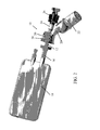
Fig. 1 is a pictorial illustration of a vial adapter modular assembly for a drug mixing system, constructed and operative in accordance with an embodiment of the present invention, for serial connection to another vial adapter modular assembly, and showing a vial connected to a vial port, a bag spike port closed with a cap, an exit port closed with a cap, and a vent element that has a filter; -
Fig. 2 is a pictorial illustration of the vial adapter modular assembly ofFig. 1 connected to the output port of a bag, in accordance with an embodiment of the present invention; -
Fig. 3 is a pictorial illustration of a second vial adapter modular assembly connected to the vial adapter modular assembly ofFig. 1 , in accordance with an embodiment of the present invention, and showing a vial connected to a vial port of the second vial adapter modular assembly; -
Fig. 4 is a simplified partially cutaway illustration of the vial adapter modular assembly ofFig. 1 , showing a plunger element in a position that permits fluid flow to the vial port and to the vent element, in accordance with an embodiment of the present invention; -
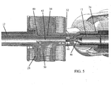
Fig. 5 is a simplified partially cutaway illustration of the vial adapter modular assembly ofFig. 1 , wherein the plunger element has been moved to a position that blocks fluid flow to the vial port and to a vent element, and fluid flow is only permitted through a needle along a longitudinal lumen of the vial adapter modular assembly towards the exit port of the vial adapter modular assembly; and -
Fig. 6 is a pictorial illustration of a vial adapter modular assembly, for a drug mixing system, constructed and operative in accordance with another embodiment of the present invention, including a closure element with a clamp that selectively closes and opens a flow conduit that leads to the vial port. - Reference is now made to
Figs. 1 and2 , which illustrate a vial adaptermodular assembly 10 for a drug mixing system, constructed and operative in accordance with an embodiment of the present invention. - Vial adapter
modular assembly 10 includes abag spike port 12, which inFig. 1 is closed with acap 14. As seen inFig. 2 ,bag spike port 12 may be connected to anoutput port 16 of a bag 18 (which may contain a mixing liquid). The connection may be effected by the spike (or needle) ofbag spike port 12 piercing a septum (not shown) ofoutput port 16 ofbag 18.Cap 14 is of course removed before connecting to the bag. - Vial adapter
modular assembly 10 also includes avial port 20 to which one connects avial 22. Again, the connection may be effected by a needle or spike ofvial port 20 piercing a septum (not shown) ofvial 22. Vial adaptermodular assembly 10 also includes anexit port 24 closed with acap 26. Vial adaptermodular assembly 10 is preferably vented, such as by avent element 28 that has afilter 30.Vent element 28 is shown inFigs. 1 and2 positioned along a lumen 32 (seen inFigs. 4-5 ) at a junction ofbag spike port 12,vial port 20 andexit port 24. Alternatively,vent element 28 may be placed elsewhere, such as at the end of one of the ports (e.g., the end of thebag spike port 12 orcap 14, as shown in dotted line inFig. 1 or along another place on lumen 32). - Vial adapter
modular assembly 10 can be used for serial connection to another vial adapter modular assembly. This is shown inFig. 3 , which illustrates a second vial adapter modular assembly 10 (the one on the right in the drawing) connected to the first vial adapter modular assembly 10 (the one on the left in the drawing).Cap 26 of the first vial adaptermodular assembly 10 has been removed and thebag spike port 12 of the second vial adaptermodular assembly 10 has been inserted into theexit port 24 of the first vial adaptermodular assembly 10. - Vial adapter
modular assembly 10 selectively seals or allows flow between thebag 18 and the first andsecond vials 22, as is now explained. - Reference is now made to
Fig. 4 . The vial adaptermodular assembly 10 includes aplunger element 34 that slides inlumen 32.Plunger element 34 may be constructed of a flexible material, such as an elastomeric material, or any other material suitable for sealing and sliding.Lumen 32 is the flow channel between the various ports of vial adaptermodular assembly 10.Lumen 32 has a vial port flow opening 36 and a vent port flow opening 38 formed therein. Vialport flow opening 36 is in fluid communication withvial port 20. Vent port flow opening 38 is in fluid communication withvent element 28. -
Fig. 4 showsplunger element 34 in a position closer to exitport 24. In this position,plunger element 34 does not block vial port flow opening 36 and 38 and permits fluid flow between bag spike port 12 (and thusbag 18, not shown inFig. 4 ) and vial port 20 (and thus vial 22). Accordingly, in this position, liquid inbag 18 may be mixed and shaken together with the contents ofvial 22 to form a solution, which may be stored temporarily in bag 18 (vial 22 being now empty). Fluid communication to ventelement 28 is open so no air is trapped that could possibly interfere with the fluid flow betweenbag 18 andvial 22.Vent element 28 ensures equilibrium of fluid pressures for proper flow. -
Fig. 5 shows the configuration ofFig. 3 , namely,Fig. 3 , the second vial adapter modular assembly has been connected to the first vial adapter modular assembly. The cap of the first vial adapter modular assembly has been twisted off or otherwise removed and thebag spike port 12 of the second vial adapter modular assembly has been inserted into theexit port 24 of the first vial adapter modular assembly. The action of insertingbag spike port 12 of the second vial adapter modular assembly into theexit port 24 of the first vial adapter modular assembly pushes theplunger element 34 of the first vial adapter modular assembly alonglumen 32 towards thebag spike port 12 of the first vial adapter modular assembly (towards the left in the sense of the drawing).Plunger 34 preferably abuts against astop 40 formed inlumen 32, thereby arresting further movement ofplunger 34 inlumen 32. In this position,plunger element 34 blocks vial port flow opening 36 and vent port flow opening 38. Now fluid cannot flow betweenbag 18 and thefirst vial 22. Instead fluid can flow betweenbag 18 and the second vial 22 (Fig. 3 ). Fluid flows frombag 18 through ahollow portion 42 ofplunger 34 out throughapertures 44 formed at a distal end ofplunger 34, then throughapertures 46 formed in a proximal end of thebag spike port 12 of the second vial adapter modular assembly. Fluid can continue to flow in this position to the second vial (not shown) because the plunger of the second vial adapter modular assembly is in the position shown inFig. 4 that permits fluid flow to the vial. - In this manner, in this position, the solution temporarily stored in bag 18 (that had been mixed with the contents of the first vial) may be mixed and shaken together with the contents of the second vial to form a solution, which again may be stored temporarily in bag 18 (the second vial being now empty). Accordingly, the vial adapter
modular assembly 10 can be used to serially mix different substances in a drug mixing system in a "daisy chain" of vials, one after the other. When the solution is finally mixed and ready for administration to a patient, an infusion set (not shown) may be connected to the exit port of the last vial adapter modular assembly. , - Reference is now made to
Fig. 6 , which illustrates a vial adapter modular assembly for a drug mixing system, constructed and operative in accordance with another embodiment of the present invention. The assembly is the same asassembly 10, except that instead of a plunger, there is aclosure element 50 with a clamp that selectively closes and opens aflow conduit 52 that leads to thevial port 20.
Claims (10)
- A vial adapter modular assembly (10) comprising:a bag spike port (12) connectable to an output port (16) of a bag (18);a vial port (20) connectable to a vial (22); andan exit port (24),a lumen (32) having a vial port flow opening (36) in fluid communication with said vial port (20); anda closure element (34; 50) that has a non-blocking position and a blocking position, wherein in the non-blocking position, said closure element (34; 50) does not block said vial port flow opening (36) and permits fluid flow between said bag spike port (12) and said vial port (20), and wherein in the blocking position, said closure element (34; 50) blocks said vial port flow opening (36) and blocks fluid flow between said bag spike port (12) and said vial port (20);characterised by at least two said vial adapter modular assemblies (10), referred to as first and second vial adapter modular assemblies, wherein said bag spike port (12) of the second vial adapter modular assembly (10) is inserted into said exit port (24) of the first vial adapter modular assembly (10);and said bag spike port (12) of the second vial adapter modular assembly (10) is inserted into said exit port (24) of the first vial adapter modular assembly (10), thereby pushing said closure element (34; 50) of the first vial adapter modular assembly (10) along said lumen (32) to the blocking position in the first vial adapter modular assembly (10).
- The vial adapter modular assembly (10) according to claim 1, further comprising a vent element (28), wherein said lumen (32) has a vent port flow opening (38) in fluid communication with said vent element (28), and wherein in the non-blocking position, said closure element (34; 50) does not block said vent port flow opening (38)and permits fluid flow between said bag spike port (12) and said vent element (28), and wherein in the blocking position, said closure element (34; 50) blocks said vent port flow opening (38) and blocks fluid flow between said bag spike port (12) and said vent element (28).
- The vial adapter modular assembly (10) according to claim 1, wherein said closure element (34; 50) is formed with a hollow portion (42) and apertures (44) are formed at a distal end of said closure element (34; 50) from said bag spike support, wherein fluid is flowable through said hollow portion (42) and said apertures (44).
- The vial adapter modular assembly (10) according to claim 2, wherein said vent element (28) comprises a filter (30).
- The vial adapter modular assembly (10) according to claim 1, wherein said vent element (28) is positioned along said lumen (32) at a junction of said bag spike port (12), said vial port (20) and said exit port (24).
- The vial adapter modular assembly (10) according to claim 2, wherein said vent element (28) is positioned at at least one of said bag spike port (12), said vial port (20) and said exit port (24).
- The vial adapter modular assembly (10) according to any one preceding claim, further comprising a cap (26) for closing said exit port (24).
- The vial adapter modular assembly (10) according to claim 7 when dependent on claim 6, wherein said vent element (28) is positioned at at least one of said bag spike port (12), said cap (26), said vial port (20) and said exit port (24).
- The vial adapter modular assembly as claimed in any one previous claim, wherein the closure element comprises a plunger element (34) that slides in said lumen (32) between a non-blocking position and a blocking position
- The vial adapter modular assembly according to any one of claims 1 to 8, wherein said closure element (50) comprises a clamp that selectively closes and opens a flow conduit (52) that leads to said vial port (20).
Applications Claiming Priority (2)
| Application Number | Priority Date | Filing Date | Title |
|---|---|---|---|
| IL200547A IL200547A (en) | 2009-08-23 | 2009-08-23 | Multiple vial drug mixing system |
| PCT/US2010/046256 WO2011025719A1 (en) | 2009-08-23 | 2010-08-22 | Multiple vial drug mixing system |
Publications (2)
| Publication Number | Publication Date |
|---|---|
| EP2467117A1 EP2467117A1 (en) | 2012-06-27 |
| EP2467117B1 true EP2467117B1 (en) | 2015-10-28 |
Family
ID=42335673
Family Applications (1)
| Application Number | Title | Priority Date | Filing Date |
|---|---|---|---|
| EP10748186.3A Not-in-force EP2467117B1 (en) | 2009-08-23 | 2010-08-22 | Multiple vial drug mixing system |
Country Status (4)
| Country | Link |
|---|---|
| US (1) | US9486391B2 (en) |
| EP (1) | EP2467117B1 (en) |
| IL (1) | IL200547A (en) |
| WO (1) | WO2011025719A1 (en) |
Families Citing this family (24)
| Publication number | Priority date | Publication date | Assignee | Title |
|---|---|---|---|---|
| IL221634A0 (en) | 2012-08-26 | 2012-12-31 | Medimop Medical Projects Ltd | Universal drug vial adapter |
| WO2015019343A1 (en) | 2013-08-07 | 2015-02-12 | Medimop Medical Projects Ltd | Liquid transfer devices for use with infusion liquid containers |
| US11357702B2 (en) * | 2014-10-02 | 2022-06-14 | Equashield Medical Ltd. | Liquid transfer system |
| EP3217944B1 (en) | 2015-01-05 | 2019-04-10 | West Pharma. Services IL, Ltd | Dual vial adapter assemblages with quick release drug vial adapter for ensuring correct usage |
| US10357429B2 (en) | 2015-07-16 | 2019-07-23 | West Pharma. Services IL, Ltd. | Liquid drug transfer devices for secure telescopic snap fit on injection vials |
| CN115721558A (en) | 2015-11-25 | 2023-03-03 | 西部制药服务以色列有限公司 | Dual vial adapter assembly comprising a drug vial adapter having a self-sealing inlet valve |
| IL245803A0 (en) | 2016-05-24 | 2016-08-31 | West Pharma Services Il Ltd | Dual vial adapter assemblages including vented drug vial adapter and vented liquid vial adapter |
| IL245800A0 (en) | 2016-05-24 | 2016-08-31 | West Pharma Services Il Ltd | Dual vial adapter assemblages including identical twin vial adapters |
| IL246073A0 (en) | 2016-06-06 | 2016-08-31 | West Pharma Services Il Ltd | Fluid transfer devices for use with drug pump cartridge having slidable driving plunger |
| IL247376A0 (en) | 2016-08-21 | 2016-12-29 | Medimop Medical Projects Ltd | Syringe assembly |
| IL249408A0 (en) | 2016-12-06 | 2017-03-30 | Medimop Medical Projects Ltd | A device for transporting fluids for use with an infusion fluid container and a hand tool similar to a plunger to release a vial from it |
| IL251458A0 (en) | 2017-03-29 | 2017-06-29 | Medimop Medical Projects Ltd | User actuated liquid drug transfer devices for use in ready-to-use (rtu) liquid drug transfer assemblages |
| IL254802A0 (en) | 2017-09-29 | 2017-12-31 | Medimop Medical Projects Ltd | Dual vial adapter assemblages with twin vented female vial adapters |
| JP6850400B2 (en) | 2017-12-03 | 2021-03-31 | ウェスト ファーマ サービシーズ イスラエル リミテッド | Infusion device with telescopic bottle adapter for use with infusion container and another infusion bottle |
| USD903864S1 (en) | 2018-06-20 | 2020-12-01 | West Pharma. Services IL, Ltd. | Medication mixing apparatus |
| JP1630477S (en) | 2018-07-06 | 2019-05-07 | ||
| USD923812S1 (en) | 2019-01-16 | 2021-06-29 | West Pharma. Services IL, Ltd. | Medication mixing apparatus |
| JP1648075S (en) | 2019-01-17 | 2019-12-16 | ||
| EP3911292B1 (en) | 2019-01-18 | 2022-12-28 | West Pharma Services IL, Ltd. | Liquid transfer devices for use with intravenous (iv) bottles |
| US11918542B2 (en) | 2019-01-31 | 2024-03-05 | West Pharma. Services IL, Ltd. | Liquid transfer device |
| CN113677382B (en) * | 2019-04-09 | 2023-06-09 | 西医药服务以色列有限公司 | Liquid delivery device with integrated syringe |
| KR102692155B1 (en) | 2019-04-30 | 2024-08-06 | 웨스트 파마. 서비시즈 일, 리미티드 | Liquid delivery device with dual lumen IV spikes |
| USD956958S1 (en) | 2020-07-13 | 2022-07-05 | West Pharma. Services IL, Ltd. | Liquid transfer device |
| CA3198353A1 (en) | 2020-10-09 | 2022-04-14 | Icu Medical, Inc. | Fluid transfer device and method of use for same |
Family Cites Families (8)
| Publication number | Priority date | Publication date | Assignee | Title |
|---|---|---|---|---|
| US5484406A (en) * | 1992-11-19 | 1996-01-16 | Baxter International Inc. | In-line drug delivery device for use with a standard IV administration set and a method for delivery |
| US5405333A (en) * | 1992-12-28 | 1995-04-11 | Richmond; Frank M. | Liquid medicament bag with needleless connector fitting using boat assembly |
| US5658271A (en) | 1996-02-08 | 1997-08-19 | Loubser; Paul G. | Closed circuit autologous sequestration reservoir system |
| US20040073189A1 (en) * | 2002-10-09 | 2004-04-15 | Phil Wyatt | Vial access transfer set |
| SI2664550T1 (en) | 2003-10-30 | 2020-03-31 | Simplivia Healtcare Ltd., | Safety Drug Handling Device |
| FR2869533B1 (en) * | 2004-05-03 | 2006-07-28 | Sedat Sa | SYRINGE FOR MEDICAL INTERVENTIONS AND NECESSARY FOR RECONSTITUTION OF EXTEMPORANEOUS SUBSTANCES COMPRISING SUCH A SYRINGE |
| US7862537B2 (en) * | 2005-02-14 | 2011-01-04 | Medimop Medical Projects Ltd. | Medical device for in situ liquid drug reconstitution in medicinal vessels |
| IL182605A0 (en) * | 2007-04-17 | 2007-07-24 | Medimop Medical Projects Ltd | Fluid control device with manually depressed actuator |
-
2009
- 2009-08-23 IL IL200547A patent/IL200547A/en active IP Right Grant
-
2010
- 2010-08-22 EP EP10748186.3A patent/EP2467117B1/en not_active Not-in-force
- 2010-08-22 WO PCT/US2010/046256 patent/WO2011025719A1/en not_active Ceased
- 2010-08-22 US US13/390,939 patent/US9486391B2/en not_active Expired - Fee Related
Also Published As
| Publication number | Publication date |
|---|---|
| IL200547A (en) | 2014-06-30 |
| WO2011025719A1 (en) | 2011-03-03 |
| US9486391B2 (en) | 2016-11-08 |
| IL200547A0 (en) | 2010-05-17 |
| EP2467117A1 (en) | 2012-06-27 |
| US20140102552A1 (en) | 2014-04-17 |
Similar Documents
| Publication | Publication Date | Title |
|---|---|---|
| EP2467117B1 (en) | Multiple vial drug mixing system | |
| US10806668B2 (en) | Method and assembly for fluid transfer and drug containment in an infusion system | |
| US6228065B1 (en) | Displacement activated medical check valve | |
| US5897526A (en) | Closed system medication administering system | |
| DK1957028T3 (en) | Needleless additive control valve | |
| EP1368078B1 (en) | Drug delivery system | |
| KR101507841B1 (en) | Method and apparatus for contamination-free transfer of a hazardous drug | |
| US7637889B2 (en) | Drug delivery device with sliding valve and methodology | |
| EP2437715B1 (en) | Multi-container transfer and delivery device | |
| KR20240154676A (en) | Pooling device for single or multiple containers | |
| US12274671B2 (en) | Sterile flexible package with pressure compensator for the dosed reconstitution of fluid medicinal or nutritional substances to be administered to patients by infusion or injection | |
| KR102839673B1 (en) | Sterile or sterilized package for administration of medicinal or nutritional substances | |
| EP4000588B1 (en) | Assembly with connectable and disconnectable elements for the reconstitution of fluid drugs and nutrients with active substances in powder, liquid or gel form, and related method of use | |
| KR20240125671A (en) | Pressure compensating device for reconstituting, withdrawing and delivering a drug from a vial or other vacuum container and an apparatus including said device | |
| AU2002252082B2 (en) | Drug delivery system | |
| AU2002252082A1 (en) | Drug delivery system |
Legal Events
| Date | Code | Title | Description |
|---|---|---|---|
| PUAI | Public reference made under article 153(3) epc to a published international application that has entered the european phase |
Free format text: ORIGINAL CODE: 0009012 |
|
| 17P | Request for examination filed |
Effective date: 20120320 |
|
| AK | Designated contracting states |
Kind code of ref document: A1 Designated state(s): AL AT BE BG CH CY CZ DE DK EE ES FI FR GB GR HR HU IE IS IT LI LT LU LV MC MK MT NL NO PL PT RO SE SI SK SM TR |
|
| DAX | Request for extension of the european patent (deleted) | ||
| RIC1 | Information provided on ipc code assigned before grant |
Ipc: A61J 1/20 20060101AFI20150323BHEP Ipc: A61J 1/10 20060101ALN20150323BHEP |
|
| GRAP | Despatch of communication of intention to grant a patent |
Free format text: ORIGINAL CODE: EPIDOSNIGR1 |
|
| INTG | Intention to grant announced |
Effective date: 20150506 |
|
| GRAS | Grant fee paid |
Free format text: ORIGINAL CODE: EPIDOSNIGR3 |
|
| GRAA | (expected) grant |
Free format text: ORIGINAL CODE: 0009210 |
|
| AK | Designated contracting states |
Kind code of ref document: B1 Designated state(s): AL AT BE BG CH CY CZ DE DK EE ES FI FR GB GR HR HU IE IS IT LI LT LU LV MC MK MT NL NO PL PT RO SE SI SK SM TR |
|
| REG | Reference to a national code |
Ref country code: GB Ref legal event code: FG4D |
|
| REG | Reference to a national code |
Ref country code: CH Ref legal event code: EP |
|
| REG | Reference to a national code |
Ref country code: AT Ref legal event code: REF Ref document number: 757530 Country of ref document: AT Kind code of ref document: T Effective date: 20151115 |
|
| REG | Reference to a national code |
Ref country code: IE Ref legal event code: FG4D |
|
| REG | Reference to a national code |
Ref country code: DE Ref legal event code: R096 Ref document number: 602010028621 Country of ref document: DE |
|
| REG | Reference to a national code |
Ref country code: SE Ref legal event code: TRGR |
|
| REG | Reference to a national code |
Ref country code: LT Ref legal event code: MG4D |
|
| REG | Reference to a national code |
Ref country code: NL Ref legal event code: MP Effective date: 20151028 |
|
| REG | Reference to a national code |
Ref country code: AT Ref legal event code: MK05 Ref document number: 757530 Country of ref document: AT Kind code of ref document: T Effective date: 20151028 |
|
| PG25 | Lapsed in a contracting state [announced via postgrant information from national office to epo] |
Ref country code: IT Free format text: LAPSE BECAUSE OF FAILURE TO SUBMIT A TRANSLATION OF THE DESCRIPTION OR TO PAY THE FEE WITHIN THE PRESCRIBED TIME-LIMIT Effective date: 20151028 Ref country code: ES Free format text: LAPSE BECAUSE OF FAILURE TO SUBMIT A TRANSLATION OF THE DESCRIPTION OR TO PAY THE FEE WITHIN THE PRESCRIBED TIME-LIMIT Effective date: 20151028 Ref country code: NO Free format text: LAPSE BECAUSE OF FAILURE TO SUBMIT A TRANSLATION OF THE DESCRIPTION OR TO PAY THE FEE WITHIN THE PRESCRIBED TIME-LIMIT Effective date: 20160128 Ref country code: NL Free format text: LAPSE BECAUSE OF FAILURE TO SUBMIT A TRANSLATION OF THE DESCRIPTION OR TO PAY THE FEE WITHIN THE PRESCRIBED TIME-LIMIT Effective date: 20151028 Ref country code: IS Free format text: LAPSE BECAUSE OF FAILURE TO SUBMIT A TRANSLATION OF THE DESCRIPTION OR TO PAY THE FEE WITHIN THE PRESCRIBED TIME-LIMIT Effective date: 20160228 Ref country code: LT Free format text: LAPSE BECAUSE OF FAILURE TO SUBMIT A TRANSLATION OF THE DESCRIPTION OR TO PAY THE FEE WITHIN THE PRESCRIBED TIME-LIMIT Effective date: 20151028 Ref country code: HR Free format text: LAPSE BECAUSE OF FAILURE TO SUBMIT A TRANSLATION OF THE DESCRIPTION OR TO PAY THE FEE WITHIN THE PRESCRIBED TIME-LIMIT Effective date: 20151028 |
|
| PG25 | Lapsed in a contracting state [announced via postgrant information from national office to epo] |
Ref country code: FI Free format text: LAPSE BECAUSE OF FAILURE TO SUBMIT A TRANSLATION OF THE DESCRIPTION OR TO PAY THE FEE WITHIN THE PRESCRIBED TIME-LIMIT Effective date: 20151028 Ref country code: AT Free format text: LAPSE BECAUSE OF FAILURE TO SUBMIT A TRANSLATION OF THE DESCRIPTION OR TO PAY THE FEE WITHIN THE PRESCRIBED TIME-LIMIT Effective date: 20151028 Ref country code: LV Free format text: LAPSE BECAUSE OF FAILURE TO SUBMIT A TRANSLATION OF THE DESCRIPTION OR TO PAY THE FEE WITHIN THE PRESCRIBED TIME-LIMIT Effective date: 20151028 Ref country code: GR Free format text: LAPSE BECAUSE OF FAILURE TO SUBMIT A TRANSLATION OF THE DESCRIPTION OR TO PAY THE FEE WITHIN THE PRESCRIBED TIME-LIMIT Effective date: 20160129 Ref country code: PT Free format text: LAPSE BECAUSE OF FAILURE TO SUBMIT A TRANSLATION OF THE DESCRIPTION OR TO PAY THE FEE WITHIN THE PRESCRIBED TIME-LIMIT Effective date: 20160229 Ref country code: PL Free format text: LAPSE BECAUSE OF FAILURE TO SUBMIT A TRANSLATION OF THE DESCRIPTION OR TO PAY THE FEE WITHIN THE PRESCRIBED TIME-LIMIT Effective date: 20151028 |
|
| PG25 | Lapsed in a contracting state [announced via postgrant information from national office to epo] |
Ref country code: CZ Free format text: LAPSE BECAUSE OF FAILURE TO SUBMIT A TRANSLATION OF THE DESCRIPTION OR TO PAY THE FEE WITHIN THE PRESCRIBED TIME-LIMIT Effective date: 20151028 |
|
| REG | Reference to a national code |
Ref country code: DE Ref legal event code: R097 Ref document number: 602010028621 Country of ref document: DE |
|
| REG | Reference to a national code |
Ref country code: FR Ref legal event code: PLFP Year of fee payment: 7 |
|
| PG25 | Lapsed in a contracting state [announced via postgrant information from national office to epo] |
Ref country code: DK Free format text: LAPSE BECAUSE OF FAILURE TO SUBMIT A TRANSLATION OF THE DESCRIPTION OR TO PAY THE FEE WITHIN THE PRESCRIBED TIME-LIMIT Effective date: 20151028 Ref country code: SK Free format text: LAPSE BECAUSE OF FAILURE TO SUBMIT A TRANSLATION OF THE DESCRIPTION OR TO PAY THE FEE WITHIN THE PRESCRIBED TIME-LIMIT Effective date: 20151028 Ref country code: RO Free format text: LAPSE BECAUSE OF FAILURE TO SUBMIT A TRANSLATION OF THE DESCRIPTION OR TO PAY THE FEE WITHIN THE PRESCRIBED TIME-LIMIT Effective date: 20151028 Ref country code: EE Free format text: LAPSE BECAUSE OF FAILURE TO SUBMIT A TRANSLATION OF THE DESCRIPTION OR TO PAY THE FEE WITHIN THE PRESCRIBED TIME-LIMIT Effective date: 20151028 Ref country code: SM Free format text: LAPSE BECAUSE OF FAILURE TO SUBMIT A TRANSLATION OF THE DESCRIPTION OR TO PAY THE FEE WITHIN THE PRESCRIBED TIME-LIMIT Effective date: 20151028 |
|
| PLBE | No opposition filed within time limit |
Free format text: ORIGINAL CODE: 0009261 |
|
| STAA | Information on the status of an ep patent application or granted ep patent |
Free format text: STATUS: NO OPPOSITION FILED WITHIN TIME LIMIT |
|
| 26N | No opposition filed |
Effective date: 20160729 |
|
| PG25 | Lapsed in a contracting state [announced via postgrant information from national office to epo] |
Ref country code: SI Free format text: LAPSE BECAUSE OF FAILURE TO SUBMIT A TRANSLATION OF THE DESCRIPTION OR TO PAY THE FEE WITHIN THE PRESCRIBED TIME-LIMIT Effective date: 20151028 |
|
| PG25 | Lapsed in a contracting state [announced via postgrant information from national office to epo] |
Ref country code: MC Free format text: LAPSE BECAUSE OF FAILURE TO SUBMIT A TRANSLATION OF THE DESCRIPTION OR TO PAY THE FEE WITHIN THE PRESCRIBED TIME-LIMIT Effective date: 20151028 |
|
| REG | Reference to a national code |
Ref country code: IE Ref legal event code: MM4A |
|
| PG25 | Lapsed in a contracting state [announced via postgrant information from national office to epo] |
Ref country code: IE Free format text: LAPSE BECAUSE OF NON-PAYMENT OF DUE FEES Effective date: 20160822 |
|
| REG | Reference to a national code |
Ref country code: FR Ref legal event code: PLFP Year of fee payment: 8 |
|
| PG25 | Lapsed in a contracting state [announced via postgrant information from national office to epo] |
Ref country code: LU Free format text: LAPSE BECAUSE OF NON-PAYMENT OF DUE FEES Effective date: 20160822 |
|
| PG25 | Lapsed in a contracting state [announced via postgrant information from national office to epo] |
Ref country code: HU Free format text: LAPSE BECAUSE OF FAILURE TO SUBMIT A TRANSLATION OF THE DESCRIPTION OR TO PAY THE FEE WITHIN THE PRESCRIBED TIME-LIMIT; INVALID AB INITIO Effective date: 20100822 Ref country code: CY Free format text: LAPSE BECAUSE OF FAILURE TO SUBMIT A TRANSLATION OF THE DESCRIPTION OR TO PAY THE FEE WITHIN THE PRESCRIBED TIME-LIMIT Effective date: 20151028 |
|
| PG25 | Lapsed in a contracting state [announced via postgrant information from national office to epo] |
Ref country code: MT Free format text: LAPSE BECAUSE OF NON-PAYMENT OF DUE FEES Effective date: 20160831 Ref country code: TR Free format text: LAPSE BECAUSE OF FAILURE TO SUBMIT A TRANSLATION OF THE DESCRIPTION OR TO PAY THE FEE WITHIN THE PRESCRIBED TIME-LIMIT Effective date: 20151028 Ref country code: MK Free format text: LAPSE BECAUSE OF FAILURE TO SUBMIT A TRANSLATION OF THE DESCRIPTION OR TO PAY THE FEE WITHIN THE PRESCRIBED TIME-LIMIT Effective date: 20151028 |
|
| PG25 | Lapsed in a contracting state [announced via postgrant information from national office to epo] |
Ref country code: BG Free format text: LAPSE BECAUSE OF FAILURE TO SUBMIT A TRANSLATION OF THE DESCRIPTION OR TO PAY THE FEE WITHIN THE PRESCRIBED TIME-LIMIT Effective date: 20151028 |
|
| REG | Reference to a national code |
Ref country code: FR Ref legal event code: PLFP Year of fee payment: 9 |
|
| PG25 | Lapsed in a contracting state [announced via postgrant information from national office to epo] |
Ref country code: AL Free format text: LAPSE BECAUSE OF FAILURE TO SUBMIT A TRANSLATION OF THE DESCRIPTION OR TO PAY THE FEE WITHIN THE PRESCRIBED TIME-LIMIT Effective date: 20151028 |
|
| PGFP | Annual fee paid to national office [announced via postgrant information from national office to epo] |
Ref country code: SE Payment date: 20190821 Year of fee payment: 10 Ref country code: FR Payment date: 20190822 Year of fee payment: 10 Ref country code: DE Payment date: 20190822 Year of fee payment: 10 |
|
| PGFP | Annual fee paid to national office [announced via postgrant information from national office to epo] |
Ref country code: BE Payment date: 20190821 Year of fee payment: 10 |
|
| PGFP | Annual fee paid to national office [announced via postgrant information from national office to epo] |
Ref country code: GB Payment date: 20190821 Year of fee payment: 10 |
|
| PGFP | Annual fee paid to national office [announced via postgrant information from national office to epo] |
Ref country code: CH Payment date: 20190821 Year of fee payment: 10 |
|
| REG | Reference to a national code |
Ref country code: DE Ref legal event code: R119 Ref document number: 602010028621 Country of ref document: DE |
|
| REG | Reference to a national code |
Ref country code: SE Ref legal event code: EUG |
|
| REG | Reference to a national code |
Ref country code: CH Ref legal event code: PL |
|
| GBPC | Gb: european patent ceased through non-payment of renewal fee |
Effective date: 20200822 |
|
| PG25 | Lapsed in a contracting state [announced via postgrant information from national office to epo] |
Ref country code: CH Free format text: LAPSE BECAUSE OF NON-PAYMENT OF DUE FEES Effective date: 20200831 Ref country code: LI Free format text: LAPSE BECAUSE OF NON-PAYMENT OF DUE FEES Effective date: 20200831 |
|
| REG | Reference to a national code |
Ref country code: BE Ref legal event code: MM Effective date: 20200831 |
|
| PG25 | Lapsed in a contracting state [announced via postgrant information from national office to epo] |
Ref country code: SE Free format text: LAPSE BECAUSE OF NON-PAYMENT OF DUE FEES Effective date: 20200823 |
|
| PG25 | Lapsed in a contracting state [announced via postgrant information from national office to epo] |
Ref country code: FR Free format text: LAPSE BECAUSE OF NON-PAYMENT OF DUE FEES Effective date: 20200831 Ref country code: DE Free format text: LAPSE BECAUSE OF NON-PAYMENT OF DUE FEES Effective date: 20210302 |
|
| PG25 | Lapsed in a contracting state [announced via postgrant information from national office to epo] |
Ref country code: GB Free format text: LAPSE BECAUSE OF NON-PAYMENT OF DUE FEES Effective date: 20200822 Ref country code: BE Free format text: LAPSE BECAUSE OF NON-PAYMENT OF DUE FEES Effective date: 20200831 |