EP3527113A1 - Cooking appliance - Google Patents
Cooking appliance Download PDFInfo
- Publication number
- EP3527113A1 EP3527113A1 EP17859822.3A EP17859822A EP3527113A1 EP 3527113 A1 EP3527113 A1 EP 3527113A1 EP 17859822 A EP17859822 A EP 17859822A EP 3527113 A1 EP3527113 A1 EP 3527113A1
- Authority
- EP
- European Patent Office
- Prior art keywords
- cover
- cooking appliance
- control panel
- pot
- assembly
- Prior art date
- Legal status (The legal status is an assumption and is not a legal conclusion. Google has not performed a legal analysis and makes no representation as to the accuracy of the status listed.)
- Granted
Links
Images





Classifications
-
- A—HUMAN NECESSITIES
- A47—FURNITURE; DOMESTIC ARTICLES OR APPLIANCES; COFFEE MILLS; SPICE MILLS; SUCTION CLEANERS IN GENERAL
- A47J—KITCHEN EQUIPMENT; COFFEE MILLS; SPICE MILLS; APPARATUS FOR MAKING BEVERAGES
- A47J27/00—Cooking-vessels
- A47J27/08—Pressure-cookers; Lids or locking devices specially adapted therefor
- A47J27/0802—Control mechanisms for pressure-cookers
-
- A—HUMAN NECESSITIES
- A47—FURNITURE; DOMESTIC ARTICLES OR APPLIANCES; COFFEE MILLS; SPICE MILLS; SUCTION CLEANERS IN GENERAL
- A47J—KITCHEN EQUIPMENT; COFFEE MILLS; SPICE MILLS; APPARATUS FOR MAKING BEVERAGES
- A47J36/00—Parts, details or accessories of cooking-vessels
- A47J36/32—Time-controlled igniting mechanisms or alarm devices
-
- A—HUMAN NECESSITIES
- A47—FURNITURE; DOMESTIC ARTICLES OR APPLIANCES; COFFEE MILLS; SPICE MILLS; SUCTION CLEANERS IN GENERAL
- A47J—KITCHEN EQUIPMENT; COFFEE MILLS; SPICE MILLS; APPARATUS FOR MAKING BEVERAGES
- A47J27/00—Cooking-vessels
- A47J27/08—Pressure-cookers; Lids or locking devices specially adapted therefor
- A47J27/086—Pressure-cookers; Lids or locking devices specially adapted therefor with built-in heating means
Definitions
- the present disclosure relates to a technical field of cooking appliances, and more particularly, to a cooking appliance.
- the existing products are not designed to effectively separate control panels configured to control two types of functions, i.e., cooking functions in a cover-closed state and cooking functions in a cover-open state, and a situation where the cooking function supposed to be performed in the cover-open state is operated in the cover-closed state may occur, which leads to cooking failure and even product damage in serious cases.
- An objective of the present disclosure is to provide a cooking appliance, which can effectively avoid misoperation in a cover-open state and a cover-closed state, and improve the operation convenience and reliability of the cooking appliance.
- the present disclosure provides a cooking appliance including a pot body assembly and a pot cover assembly, in which the pot cover assembly can cover the pot body assembly in an openable and closable manner.
- the cooking appliance includes a cover-closed state and a cover-open state; the cooking appliance further includes a first control panel working in the cover-open state and a second control panel working in the cover-closed state.
- the pot cover assembly covers the first control panel in the cover-closed state.
- the first control panel is disposed on a top surface of the pot body assembly.
- the top surface of the pot body assembly is provided with a table top, and the table top is provided with a first area configured to mount the first control panel, and the pot cover assembly is provided with a shielding part configured to shield the first area in the cover-closed state.
- the table top is also provided with a second area configured to mount the second control panel, and the pot cover assembly is provided with a relief space to avoid the second area in the cover-closed state.
- the second control panel is disposed to a side surface of the pot body assembly or a surface of the pot cover assembly.
- the second control panel is provided with a control knob configured to adjust a working state of the cooking appliance.
- the center of the control knob is provided with a cover opening button configured to open the pot cover assembly.
- the cooking appliance further includes a controller, a first control circuit and a second control circuit, in which the first control panel is connected to the controller by the first control circuit, and the second control panel is connected to the controller by the second control circuit.
- the controller controls to connect the first control circuit and disconnect the second control circuit when the cooking appliance is in the cover-open state; the controller controls to connect the second control circuit and disconnect the first control circuit when the cooking appliance is in the cover-closed state.
- the cooking appliance further includes a detection component.
- the detection component is configured to detect a working state of the cooking appliance in the cover-closed state or the cover-open state, and transmit the detected working state to the controller.
- the detection component includes a pressure sensor disposed on the first control panel and a triggering member disposed correspondingly to the pot cover assembly, and the pressure sensor is pressed against the triggering member and generates a pressure signal to be transmitted to the controller in the cover-closed state.
- both the first control panel and the second control panel are provided with a functional control key.
- the first control panel is disposed on a lower surface of the pot cover assembly in the cover-closed state.
- the cooking appliance is an electric pressure cooker or an electric rice cooker.
- the present disclosure divides the existing control panel into the first control panel working in the cover-open state and the second control panel working in the cover-closed state, and the first control panel is covered by the pot cover assembly in the cover-closed state, such that it cannot be manipulated. Therefore, the user can only control the second control panel in the cover-closed state, and can only start and control a cover-open cooking function in the cover-open state, thus avoiding cooking failure or product damage caused by the user's misoperation of controlling the cover-open cooking function in the cover-closed state, and improving the operation convenience and reliability of the cooking appliance.
- pot cover assembly 1, pot body assembly 2, first control panel 3, second control panel 4, functional control key 5, display screen 6, control knob 7, cover opening button 8, first area 21, and second area 22.
- orientation terms such as “up,” “down,” “top,” and “bottom” used herein refer to an electric rice cooker shown in Fig. 1 under a normal use condition, or describe the mutual positional relationship of components in the upright, vertical or gravity direction; orientation terms such as “inner” and “outer” generally refer to the interior and exterior of a chamber relative to the chamber.
- the present disclosure provides a cooking appliance.
- the cooking appliance includes a pot body assembly 2 and a pot cover assembly 1, in which the pot cover assembly 1 can cover the pot body assembly 2 in an openable and closable manner.
- the cooking appliance includes a cover-closed state and a cover-open state.
- the cooking appliance further includes a first control panel 3 working in the cover-open state and a second control panel 4 working in the cover-closed state.
- the pot cover assembly 1 covers the first control panel 3 in the cover-closed state.
- the present disclosure improves the existing control panel and divides it into the first control panel 3 working in the cover-open state and the second control panel 4 working in the cover-closed state; and the first control panel 3 is covered by the pot cover assembly 1 in the cover-closed state, such that the first control panel 3 cannot be manipulated. Therefore, the user can only manipulate the second control panel 4 in the cover-closed state, and can activate the first control panel 3 only in the cover-open state to control a cover-open cooking function, thus avoiding cooking failure or product damage caused by the user's misoperation of controlling the cover-open cooking function in the cover-closed state, and improving the operation convenience and reliability of the cooking appliance.
- the first control panel 3 is disposed on a top surface of the pot body assembly 2.
- the pot cover assembly 1 it is convenient for the pot cover assembly 1 to cover the first control panel 3 to effect the separation of the first control panel 3 and the second control panel 4.
- the second control panel 4 is disposed on a top surface of the pot cover assembly 1, and the first control panel 3 is disposed on the top surface of the pot body assembly 2.
- the top surface of the pot body assembly 2 is provided with a table top, and the table top is provided with a first area 21 configured to mount the first control panel 3.
- the pot cover assembly 1 is provided with a shielding part configured to shield the first area 21 in the cover-closed state, such that the pot cover assembly 1 can cover the first control panel 3. As shown in Fig.
- the pot cover assembly 1 in the cover-closed state, covers the first control panel 3 on the top surface of the pot body assembly 2, and only the second control panel 4 on the top surface of the pot cover assembly 1 is exposed to the outside, such that the first control panel 3 and the second control panel 4 are separated, and the user can conveniently control the cooking appliance to cook in the cover-closed state through the second control panel 4.
- the second control panel 4 in the cover-open state, is flipped up to a rear side together with the pot cover assembly 1, and only the first control panel 3 on the top surface of the pot body assembly 2 is exposed to the outside, such that the user controls the cooking appliance to cook in the cover-open state through the first control panel 3.
- the present disclosure overcomes a defect that a top-mounted control panel of an existing high-end conjoined product is flipped up to the rear side with the pot cover assembly 1 in the cover-open state, making it very inconvenient for the user to cook in the cover-open state.
- the cooking appliance of the present disclosure can still easily perform the cover-open cooking function in the cover-open state, such that the operation convenience of the cooking appliance is further improved.
- Figs. 3 and 4 show stereograms of a cooking appliance according to a second embodiment of the present disclosure.
- the second control panel 4 is disposed to a surface of the pot cover assembly 1
- the first control panel 3 is disposed on the top surface of the pot body assembly 2.
- the second control panel 4 of the surface of the pot cover assembly 1 is always exposed to the outside regardless of whether it is in the cover-closed state or in the cover-open state. Further referring to Fig.
- the pot cover assembly 1 covers the first control panel 3 on the top surface of the pot body assembly 2, so that the first control panel 3 and the second control panel 4 are separated to make it convenient for the user to control the cooking appliance to cook in the cover-closed state by the second control panel 4.
- the first control panel 3 of the top surface of the pot body assembly 2 is exposed to the outside, and the user controls the cooking appliance to cook in the cover-open state by the first control panel 3.
- the first control panel 3 and the second control panel 4 are disposed on different surfaces of the pot cover assembly 1 to separate the first control panel 3 and the second control panel 4, so as to avoid misoperation by the user.
- the first control panel 3 directly faces the user, such that the user will not manipulate the second control panel 4 on the surface of the pot body assembly 2, thereby facilitating cooking by the user in the cover-open state and further avoiding cooking failure and product damage caused by misoperation of the user.
- the top surface of the pot body assembly 2 is provided with a table top, and the table top is provided with a first area 21 configured to mount the first control panel 3; the pot cover assembly 1 is provided with a shielding part configured to shield the first area 21 in the cover-closed state.
- the table top on the top surface of the pot body assembly 2 is also provided with a second area 22 configured to mount the second control panel 4; and the pot cover assembly 1 is provided with a relief space to avoid the second area 22 in the cover-closed state.
- the relief space of the pot cover assembly 1 can be a hole provided in a pot cover when the pot cover assembly 1 has the same size as the top surface of the pot body assembly 2. In the cover-closed state, the pot cover assembly 1 can cover the first control panel 3, and the hole exposes the second control panel 4 disposed on the top surface of the pot body assembly 2, such that the user can only operate the second control panel 4.
- the relief space can be formed by designing the pot cover assembly 1 to a shorter size; a front end of the pot cover assembly 1 defines the relief space to avoid the second area 22 provided at a front end of the top surface of the pot body assembly 2 when the cover is closed, so as to expose the second control panel 4.
- the top surface of the pot body assembly 2 includes a pot-cover-assembly coverage area (i.e., the first area 21) provided with the first control panel 3 and a pot-cover-assembly non-coverage area (i.e., the second area 22) provided with the second control panel 4.
- the pot cover assembly 1 covers the pot-cover-assembly coverage area.
- the top surface of the pot body assembly 2 is divided into the pot-cover-assembly coverage area and the pot-cover-assembly non-coverage area by a covering effect of the pot cover assembly 1, and the first control panel 3 is arranged in the pot-cover-assembly coverage area, such that only the second control panel 4 is exposed outside while the first control panel 3 is covered by the pot cover assembly 1 in the cover-closed state, thereby enabling the user to manipulate the second control panel 4 to realize a cover-closed cooking function of the cooking appliance.
- the pot cover assembly 1 is flipped up to expose the first control panel 3, such that the user can distinguish the first control panel 3 from the second control panel 4, and can perform cooking in the cover-open state conveniently.
- the second control panel 4 is provided with a control knob 7 configured to adjust a working state of the cooking appliance.
- the center of the control knob 7 is provided with a cover opening button 8 configured to open the pot cover assembly 1.
- cooking parameters such as temperature, pressure, time, etc. can be adjusted by turning the knob 7, and an upper cover can be opened by pressing the cover opening button 8.
- the cooking appliance further includes a controller, a first control circuit and a second control circuit.
- the first control panel 3 is connected to the controller by the first control circuit
- the second control panel 4 is connected to the controller by the second control circuit.
- the controller controls to connect the second control circuit and disconnect the first control circuit;
- the controller controls to connect the first control circuit and disconnect the second control circuit.
- the user in the cover-open state, the user can only manipulate the first control panel 3 to start the cooking appliance and perform the corresponding cooking function, and even if the user mistakenly operates the second control panel 4, the cooking function of the cooking appliance will not be affected; on the contrary, in the cover-closed state, the user can only manipulate the second control panel 4 to start the cooking appliance and perform the corresponding cooking function, and the user has no access to the first control panel 3 in the cover-closed state, thus avoiding the possibility of misoperation by the user.
- the cooking appliance further includes a detection component configured to detect the working state of the cooking appliance in the cover-closed state or the cover-open state, and transmit the detected working state to the controller.
- the detection component may be a sensor through which it can be known that the pot cover assembly 1 of the cooking appliance is in the cover-open state or the cover-closed state.
- the sensor may be disposed on the top surface of the pot body assembly 2 or preferably on the first control panel 3, or provided to a contact surface of the pot cover assembly 1 with the pot body assembly 2.
- the detection component includes a pressure sensor provided on the first control panel 3 and a triggering member provided correspondingly to the pot cover assembly 1.
- the pressure sensor In the cover-closed state, the pressure sensor is pressed against the triggering member and generates a pressure signal to be transmitted to the controller.
- the pressure sensor on the first control panel 3 In the cover-closed state, the pressure sensor on the first control panel 3 is triggered by the triggering member of the pot cover assembly 1 to transmit the pressure signal generated by the pressure sensor to the controller, and then the controller controls to connect the second control circuit and disconnect the first control circuit, such that the second control panel 4 works and the first control panel 3 is disconnected.
- the contact pressure on the pressure sensor is released, and the pressure sensor transmits a release signal to the controller, and then the controller controls to connect the first control circuit and disconnect the second control circuit, such that the first control panel 3 works and the second control panel 4 is disconnected.
- the pressure sensor may be provided to a bottom surface of the pot cover assembly 1.
- the triggering member is a protrusion portion that extends from the bottom surface of the pot cover assembly 1 toward the pressure sensor.
- the pressure sensor is correspondingly formed in a recess configured to accommodate the protrusion portion.
- the present disclosure is not limited thereto, and the triggering member may be in other forms, such as a telescopic member.
- the first control panel 3 and the second control panel 4 are each provided with a functional control key 5.
- the functional control key 5 in the second control panel 4 is used to control the cooking function of the cooking appliance in the cover-closed state.
- the functional control key 5 in the second control panel 4 may refer to stewing, timing, or the like.
- the functional control key 5 in the first control panel 3 is used to control the cooking function of the cooking appliance in the cover-open state.
- the functional control key 5 in the first control panel 3 may refer to frying, decoction, stir-frying, etc.
- the first control panel 3 and the second control panel 4 may also be provided with a display screen 6.
- the display screen 6 is electrically connected to the functional control keys 5 on the first control panel 3 and the second control panel 4, to display the function of the operated functional control key 5 and the current state of the cooking appliance on the display screen 6. For example, the function, temperature, time or the like achieved at present by the cooking appliance are displayed. It should be noted that this is not limited to keys, and the first control panel 3 and the second control panel 4 may also be touch screens.
- the first control panel 3 is provided to a lower surface of the pot cover assembly 1 in the cover-closed state, which can also realize the setting of the control panel.
- the cooking appliance of the present disclosure may take various suitable forms such as an electric pressure cooker or an electric rice cooker.
- the cooking appliance is an electric pressure cooker.
- the present disclosure improves the existing control panel and divides it into the first control panel 3 working in the cover-open state and the second control panel 4 working in the cover-closed state, and the first control panel 3 is covered by the pot cover assembly 1 in the cover-closed state, such that the first control panel 3 cannot be manipulated. Therefore, the user can only manipulate the second control panel 4 in the cover-closed state, and can activate the first control panel 3 only in the cover-open state to control the cover-open cooking function, thus avoiding cooking failure or product damage caused by the user's misoperation of controlling the cover-open cooking function in the cover-closed state, and improving the operation convenience and reliability of the cooking appliance.
- the present disclosure overcomes the defect that the top-mounted control panel of the existing high-end conjoined product is flipped over to the rear side with the pot cover when in the cover-open state, making it very inconvenient for the user to cook in the cover-open state.
- the cooking appliance of the present disclosure can still easily perform the cover-open cooking function in the cover-open state, thereby further improving the operation convenience of the cooking appliance.
Landscapes
- Engineering & Computer Science (AREA)
- Food Science & Technology (AREA)
- Cookers (AREA)
Abstract
Description
- The present disclosure relates to a technical field of cooking appliances, and more particularly, to a cooking appliance.
- With the popularization of cooking appliances such as electric pressure cookers and rice cookers, they have been further expanded in functionality, and some functions performed in a state in which a cover is open have been incorporated, such as frying, decoction, stir-frying, stewing, and the like.
- However, the existing products are not designed to effectively separate control panels configured to control two types of functions, i.e., cooking functions in a cover-closed state and cooking functions in a cover-open state, and a situation where the cooking function supposed to be performed in the cover-open state is operated in the cover-closed state may occur, which leads to cooking failure and even product damage in serious cases.
- An objective of the present disclosure is to provide a cooking appliance, which can effectively avoid misoperation in a cover-open state and a cover-closed state, and improve the operation convenience and reliability of the cooking appliance.
- In order to achieve the above objective, the present disclosure provides a cooking appliance including a pot body assembly and a pot cover assembly, in which the pot cover assembly can cover the pot body assembly in an openable and closable manner. The cooking appliance includes a cover-closed state and a cover-open state; the cooking appliance further includes a first control panel working in the cover-open state and a second control panel working in the cover-closed state. The pot cover assembly covers the first control panel in the cover-closed state.
- According to an embodiment of the present disclosure, the first control panel is disposed on a top surface of the pot body assembly.
- According to an embodiment of the present disclosure, the top surface of the pot body assembly is provided with a table top, and the table top is provided with a first area configured to mount the first control panel, and the pot cover assembly is provided with a shielding part configured to shield the first area in the cover-closed state.
- According to an embodiment of the present disclosure, the table top is also provided with a second area configured to mount the second control panel, and the pot cover assembly is provided with a relief space to avoid the second area in the cover-closed state.
- According to an embodiment of the present disclosure, the second control panel is disposed to a side surface of the pot body assembly or a surface of the pot cover assembly.
- According to an embodiment of the present disclosure, the second control panel is provided with a control knob configured to adjust a working state of the cooking appliance.
- According to an embodiment of the present disclosure, the center of the control knob is provided with a cover opening button configured to open the pot cover assembly.
- According to an embodiment of the present disclosure, the cooking appliance further includes a controller, a first control circuit and a second control circuit, in which the first control panel is connected to the controller by the first control circuit, and the second control panel is connected to the controller by the second control circuit. The controller controls to connect the first control circuit and disconnect the second control circuit when the cooking appliance is in the cover-open state; the controller controls to connect the second control circuit and disconnect the first control circuit when the cooking appliance is in the cover-closed state.
- According to an embodiment of the present disclosure, the cooking appliance further includes a detection component. The detection component is configured to detect a working state of the cooking appliance in the cover-closed state or the cover-open state, and transmit the detected working state to the controller.
- According to an embodiment of the present disclosure, the detection component includes a pressure sensor disposed on the first control panel and a triggering member disposed correspondingly to the pot cover assembly, and the pressure sensor is pressed against the triggering member and generates a pressure signal to be transmitted to the controller in the cover-closed state.
- According to an embodiment of the present disclosure, both the first control panel and the second control panel are provided with a functional control key.
- According to an embodiment of the present disclosure, the first control panel is disposed on a lower surface of the pot cover assembly in the cover-closed state.
- According to an embodiment of the present disclosure, the cooking appliance is an electric pressure cooker or an electric rice cooker.
- Through the above technical solutions, the present disclosure divides the existing control panel into the first control panel working in the cover-open state and the second control panel working in the cover-closed state, and the first control panel is covered by the pot cover assembly in the cover-closed state, such that it cannot be manipulated. Therefore, the user can only control the second control panel in the cover-closed state, and can only start and control a cover-open cooking function in the cover-open state, thus avoiding cooking failure or product damage caused by the user's misoperation of controlling the cover-open cooking function in the cover-closed state, and improving the operation convenience and reliability of the cooking appliance.
- Additional features and advantages of the present disclosure will be given in part in the following descriptions.
- The accompanying drawings, which are incorporated in and constitute a part of this specification, together with the description, serve to explain the present disclosure, but are not intended to limit the present disclosure, in which:
-
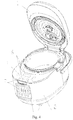
Fig. 1 is a stereogram of a cooking appliance in a cover-closed state according to a first embodiment of the present disclosure; -
Fig. 2 is a stereogram of a cooking appliance in a cover-open state according to the first embodiment of the present disclosure; -
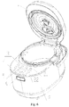
Fig. 3 is a stereogram of a cooking appliance in a cover-closed state according to a second embodiment of the present disclosure; -
Fig. 4 is a stereogram of a cooking appliance in a cover-open state according to the second embodiment of the present disclosure; -
Fig. 5 is a stereogram of a cooking appliance in a cover-open state according to a third embodiment of the present disclosure; -
Fig. 6 is a stereogram of a cooking appliance in a cover-open state according to the third embodiment of the present disclosure; -
Fig. 7 is a stereogram of a cooking appliance in a cover-closed state according to a fourth embodiment of the present disclosure; -
Fig. 8 is a stereogram of a cooking appliance in a cover-open state according to the fourth embodiment of the present disclosure; -
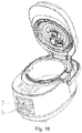
Fig. 9 is a stereogram of a cooking appliance in a cover-closed state according to a fifth embodiment of the present disclosure; and -
Fig. 10 is a stereogram of a cooking appliance in a cover-closed state according to the fifth embodiment of the present disclosure. - Reference numerals: pot cover assembly 1,
pot body assembly 2,first control panel 3,second control panel 4,functional control key 5,display screen 6,control knob 7, cover opening button 8, first area 21, andsecond area 22. - The specific embodiments of the present disclosure will be described in detail below with reference to the accompanying drawings. It should be understood that, the specific embodiments described herein are only used to explain the present disclosure rather than limit the present disclosure.
- In the present disclosure, in the absence of explanation to the contrary, orientation terms such as "up," "down," "top," and "bottom" used herein refer to an electric rice cooker shown in
Fig. 1 under a normal use condition, or describe the mutual positional relationship of components in the upright, vertical or gravity direction; orientation terms such as "inner" and "outer" generally refer to the interior and exterior of a chamber relative to the chamber. - The present disclosure provides a cooking appliance. The cooking appliance includes a
pot body assembly 2 and a pot cover assembly 1, in which the pot cover assembly 1 can cover thepot body assembly 2 in an openable and closable manner. The cooking appliance includes a cover-closed state and a cover-open state. The cooking appliance further includes afirst control panel 3 working in the cover-open state and asecond control panel 4 working in the cover-closed state. The pot cover assembly 1 covers thefirst control panel 3 in the cover-closed state. - The present disclosure improves the existing control panel and divides it into the
first control panel 3 working in the cover-open state and thesecond control panel 4 working in the cover-closed state; and thefirst control panel 3 is covered by the pot cover assembly 1 in the cover-closed state, such that thefirst control panel 3 cannot be manipulated. Therefore, the user can only manipulate thesecond control panel 4 in the cover-closed state, and can activate thefirst control panel 3 only in the cover-open state to control a cover-open cooking function, thus avoiding cooking failure or product damage caused by the user's misoperation of controlling the cover-open cooking function in the cover-closed state, and improving the operation convenience and reliability of the cooking appliance. - In particular, the
first control panel 3 is disposed on a top surface of thepot body assembly 2. By arranging thefirst control panel 3 on the top surface of thepot body assembly 2, it is convenient for the pot cover assembly 1 to cover thefirst control panel 3 to effect the separation of thefirst control panel 3 and thesecond control panel 4. - In a first embodiment of the present disclosure, referring to
Figs. 1 and2 , thesecond control panel 4 is disposed on a top surface of the pot cover assembly 1, and thefirst control panel 3 is disposed on the top surface of thepot body assembly 2. The top surface of thepot body assembly 2 is provided with a table top, and the table top is provided with a first area 21 configured to mount thefirst control panel 3. The pot cover assembly 1 is provided with a shielding part configured to shield the first area 21 in the cover-closed state, such that the pot cover assembly 1 can cover thefirst control panel 3. As shown inFig. 1 , in the cover-closed state, the pot cover assembly 1 covers thefirst control panel 3 on the top surface of thepot body assembly 2, and only thesecond control panel 4 on the top surface of the pot cover assembly 1 is exposed to the outside, such that thefirst control panel 3 and thesecond control panel 4 are separated, and the user can conveniently control the cooking appliance to cook in the cover-closed state through thesecond control panel 4. As shown inFig. 2 , in the cover-open state, thesecond control panel 4 is flipped up to a rear side together with the pot cover assembly 1, and only thefirst control panel 3 on the top surface of thepot body assembly 2 is exposed to the outside, such that the user controls the cooking appliance to cook in the cover-open state through thefirst control panel 3. Therefore, the present disclosure overcomes a defect that a top-mounted control panel of an existing high-end conjoined product is flipped up to the rear side with the pot cover assembly 1 in the cover-open state, making it very inconvenient for the user to cook in the cover-open state. The cooking appliance of the present disclosure can still easily perform the cover-open cooking function in the cover-open state, such that the operation convenience of the cooking appliance is further improved. - However, the present disclosure is not limited to the above one embodiment, and in particular,
Figs. 3 and4 show stereograms of a cooking appliance according to a second embodiment of the present disclosure. Therein, it is shown that thesecond control panel 4 is disposed to a surface of the pot cover assembly 1, and thefirst control panel 3 is disposed on the top surface of thepot body assembly 2. As shown inFigs. 3 and4 , thesecond control panel 4 of the surface of the pot cover assembly 1 is always exposed to the outside regardless of whether it is in the cover-closed state or in the cover-open state. Further referring toFig. 3 , in the cover-closed state, the pot cover assembly 1 covers thefirst control panel 3 on the top surface of thepot body assembly 2, so that thefirst control panel 3 and thesecond control panel 4 are separated to make it convenient for the user to control the cooking appliance to cook in the cover-closed state by thesecond control panel 4. Referring toFig. 4 , in the cover-open state, thefirst control panel 3 of the top surface of thepot body assembly 2 is exposed to the outside, and the user controls the cooking appliance to cook in the cover-open state by thefirst control panel 3. In this embodiment, thefirst control panel 3 and thesecond control panel 4 are disposed on different surfaces of the pot cover assembly 1 to separate thefirst control panel 3 and thesecond control panel 4, so as to avoid misoperation by the user. Further, in the cover-open state, thefirst control panel 3 directly faces the user, such that the user will not manipulate thesecond control panel 4 on the surface of thepot body assembly 2, thereby facilitating cooking by the user in the cover-open state and further avoiding cooking failure and product damage caused by misoperation of the user. - The present disclosure also provides another embodiment. In particular, the top surface of the
pot body assembly 2 is provided with a table top, and the table top is provided with a first area 21 configured to mount thefirst control panel 3; the pot cover assembly 1 is provided with a shielding part configured to shield the first area 21 in the cover-closed state. The table top on the top surface of thepot body assembly 2 is also provided with asecond area 22 configured to mount thesecond control panel 4; and the pot cover assembly 1 is provided with a relief space to avoid thesecond area 22 in the cover-closed state. It should be noted that there are many forms of relief space. For example, the relief space of the pot cover assembly 1 can be a hole provided in a pot cover when the pot cover assembly 1 has the same size as the top surface of thepot body assembly 2. In the cover-closed state, the pot cover assembly 1 can cover thefirst control panel 3, and the hole exposes thesecond control panel 4 disposed on the top surface of thepot body assembly 2, such that the user can only operate thesecond control panel 4. - As shown in
Figs. 5 and6 , the relief space can be formed by designing the pot cover assembly 1 to a shorter size; a front end of the pot cover assembly 1 defines the relief space to avoid thesecond area 22 provided at a front end of the top surface of thepot body assembly 2 when the cover is closed, so as to expose thesecond control panel 4. - Referring specifically to
Figs. 5 and6 , the top surface of thepot body assembly 2 includes a pot-cover-assembly coverage area (i.e., the first area 21) provided with thefirst control panel 3 and a pot-cover-assembly non-coverage area (i.e., the second area 22) provided with thesecond control panel 4. In the cover-closed state, the pot cover assembly 1 covers the pot-cover-assembly coverage area. In this embodiment, although thefirst control panel 3 and thesecond control panel 4 are both disposed on the top surface of thepot body assembly 2, the top surface of thepot body assembly 2 is divided into the pot-cover-assembly coverage area and the pot-cover-assembly non-coverage area by a covering effect of the pot cover assembly 1, and thefirst control panel 3 is arranged in the pot-cover-assembly coverage area, such that only thesecond control panel 4 is exposed outside while thefirst control panel 3 is covered by the pot cover assembly 1 in the cover-closed state, thereby enabling the user to manipulate thesecond control panel 4 to realize a cover-closed cooking function of the cooking appliance. In the cover-open state, the pot cover assembly 1 is flipped up to expose thefirst control panel 3, such that the user can distinguish thefirst control panel 3 from thesecond control panel 4, and can perform cooking in the cover-open state conveniently. - Referring specifically to
Figs. 7-10 , thesecond control panel 4 is provided with acontrol knob 7 configured to adjust a working state of the cooking appliance. - Further, the center of the
control knob 7 is provided with a cover opening button 8 configured to open the pot cover assembly 1. In this way, cooking parameters such as temperature, pressure, time, etc. can be adjusted by turning theknob 7, and an upper cover can be opened by pressing the cover opening button 8. - In order to further avoid cooking failure or product damage caused by the user's misoperation, in particular, the cooking appliance further includes a controller, a first control circuit and a second control circuit. The
first control panel 3 is connected to the controller by the first control circuit, and thesecond control panel 4 is connected to the controller by the second control circuit. When the cooking appliance is in the cover-closed state, the controller controls to connect the second control circuit and disconnect the first control circuit; when the cooking appliance is in the cover-open state, the controller controls to connect the first control circuit and disconnect the second control circuit. Through the control of the controller, in the cover-closed state, only thesecond control panel 4 works and thefirst control panel 3 does not work; in the cover-open state, only thefirst control panel 2 works and thesecond control panel 4 does not work. That is, in the cover-open state, the user can only manipulate thefirst control panel 3 to start the cooking appliance and perform the corresponding cooking function, and even if the user mistakenly operates thesecond control panel 4, the cooking function of the cooking appliance will not be affected; on the contrary, in the cover-closed state, the user can only manipulate thesecond control panel 4 to start the cooking appliance and perform the corresponding cooking function, and the user has no access to thefirst control panel 3 in the cover-closed state, thus avoiding the possibility of misoperation by the user. - In order to realize the function of the above controller, in particular, the cooking appliance further includes a detection component configured to detect the working state of the cooking appliance in the cover-closed state or the cover-open state, and transmit the detected working state to the controller. For example, the detection component may be a sensor through which it can be known that the pot cover assembly 1 of the cooking appliance is in the cover-open state or the cover-closed state. The sensor may be disposed on the top surface of the
pot body assembly 2 or preferably on thefirst control panel 3, or provided to a contact surface of the pot cover assembly 1 with thepot body assembly 2. - In particular, in a non-limiting manner, in a preferred embodiment of the present disclosure, the detection component includes a pressure sensor provided on the
first control panel 3 and a triggering member provided correspondingly to the pot cover assembly 1. In the cover-closed state, the pressure sensor is pressed against the triggering member and generates a pressure signal to be transmitted to the controller. In the cover-closed state, the pressure sensor on thefirst control panel 3 is triggered by the triggering member of the pot cover assembly 1 to transmit the pressure signal generated by the pressure sensor to the controller, and then the controller controls to connect the second control circuit and disconnect the first control circuit, such that thesecond control panel 4 works and thefirst control panel 3 is disconnected. On the contrary, in the cover-open state, the contact pressure on the pressure sensor is released, and the pressure sensor transmits a release signal to the controller, and then the controller controls to connect the first control circuit and disconnect the second control circuit, such that thefirst control panel 3 works and thesecond control panel 4 is disconnected. However, the present disclosure is not limited thereto, and the pressure sensor may be provided to a bottom surface of the pot cover assembly 1. - In one embodiment of the present disclosure, the triggering member is a protrusion portion that extends from the bottom surface of the pot cover assembly 1 toward the pressure sensor. The pressure sensor is correspondingly formed in a recess configured to accommodate the protrusion portion. However, the present disclosure is not limited thereto, and the triggering member may be in other forms, such as a telescopic member.
- In particular, the
first control panel 3 and thesecond control panel 4 are each provided with afunctional control key 5. Thefunctional control key 5 in thesecond control panel 4 is used to control the cooking function of the cooking appliance in the cover-closed state. For example, thefunctional control key 5 in thesecond control panel 4 may refer to stewing, timing, or the like. Thefunctional control key 5 in thefirst control panel 3 is used to control the cooking function of the cooking appliance in the cover-open state. For example, thefunctional control key 5 in thefirst control panel 3 may refer to frying, decoction, stir-frying, etc. Preferably, thefirst control panel 3 and thesecond control panel 4 may also be provided with adisplay screen 6. Thedisplay screen 6 is electrically connected to thefunctional control keys 5 on thefirst control panel 3 and thesecond control panel 4, to display the function of the operatedfunctional control key 5 and the current state of the cooking appliance on thedisplay screen 6. For example, the function, temperature, time or the like achieved at present by the cooking appliance are displayed. It should be noted that this is not limited to keys, and thefirst control panel 3 and thesecond control panel 4 may also be touch screens. - In one embodiment of the present disclosure, the
first control panel 3 is provided to a lower surface of the pot cover assembly 1 in the cover-closed state, which can also realize the setting of the control panel. - The cooking appliance of the present disclosure may take various suitable forms such as an electric pressure cooker or an electric rice cooker. In the embodiments shown in
Figs. 1 to 6 , the cooking appliance is an electric pressure cooker. - In summary, the present disclosure improves the existing control panel and divides it into the
first control panel 3 working in the cover-open state and thesecond control panel 4 working in the cover-closed state, and thefirst control panel 3 is covered by the pot cover assembly 1 in the cover-closed state, such that thefirst control panel 3 cannot be manipulated. Therefore, the user can only manipulate thesecond control panel 4 in the cover-closed state, and can activate thefirst control panel 3 only in the cover-open state to control the cover-open cooking function, thus avoiding cooking failure or product damage caused by the user's misoperation of controlling the cover-open cooking function in the cover-closed state, and improving the operation convenience and reliability of the cooking appliance. - In addition, the present disclosure overcomes the defect that the top-mounted control panel of the existing high-end conjoined product is flipped over to the rear side with the pot cover when in the cover-open state, making it very inconvenient for the user to cook in the cover-open state. The cooking appliance of the present disclosure can still easily perform the cover-open cooking function in the cover-open state, thereby further improving the operation convenience of the cooking appliance.
- The preferred embodiments of the present disclosure have been described in detail above with reference to the accompanying drawings. However, the present disclosure is not limited to the specific details in the above embodiments. Within the idea of the present disclosure, various modifications can be made to the technical solutions of the present disclosure, and these modifications are all within the protection scope of the present disclosure.
- It should be further noted that the specific technical features described in the above specific embodiments may be combined in any suitable manner without contradiction. In order to avoid unnecessary repetition, the present disclosure will not further elaborate various possible combinations.
- In addition, any combination among various embodiments of the present disclosure may be possible as long as it does not deviate from the idea of the present disclosure, and should also be regarded as the content of the present disclosure.
Claims (13)
- A cooking appliance, comprising: a pot body assembly (2), a pot cover assembly (1) and a valve body mounted on the pot cover assembly (1), the pot cover assembly (1) covering the pot body assembly (2) in an openable and closable manner,
the cooking appliance comprising a cover-closed state and a cover-open state, and
the cooking appliance further comprising a first control panel (3) working in the cover-open state and a second control panel (4) working in the cover-closed state, wherein the pot cover assembly (1) covers the first control panel (3) in the cover-closed state. - The cooking appliance according to claim 1, wherein the first control panel (3) is disposed on a top surface of the pot body assembly (2).
- The cooking appliance according to claim 2, wherein the top surface of the pot body assembly (2) is provided with a table top, the table top is provided with a first area (21) configured to install the first control panel (3), and the pot cover assembly (1) is provided with a shielding part configured to shield the first area (21) in the cover-closed state.
- The cooking appliance according to claim 3, wherein the table top is also provided with a second area (22) configured to install the second control panel (4), and the pot cover assembly (1) is provided with a relief space to avoid the second area (22) in the cover-closed state.
- The cooking appliance according to claim 2, wherein the second control panel (4) is disposed to a side surface of the pot body assembly (2) or a surface of the pot cover assembly (1).
- The cooking appliance according to claim 1, wherein the second control panel (4) is provided with a control knob (7) configured to adjust a working state of the cooking appliance.
- The cooking appliance according to claim 6, wherein the center of the control knob (7) is provided with a cover opening button (8) configured to open the pot cover assembly (1).
- The cooking appliance according to claim 1, wherein the cooking appliance further comprises a controller, a first control circuit and a second control circuit, the first control panel (3) being connected to the controller by the first control circuit, and the second control panel (4) being connected to the controller by the second control circuit;
the controller controls to connect the first control circuit and disconnect the second control circuit when the cooking appliance is in the cover-open state; the controller controls to connect the second control circuit and disconnect the first control circuit when the cooking appliance is in the cover-closed state. - The cooking appliance according to claim 8, wherein the cooking appliance further comprises a detection component configured to detect that a working state of the cooking appliance is the closed cover state or the open cover state, and transmit the detected working state to the controller.
- The cooking appliance according to claim 9, wherein the detection component comprises a pressure sensor disposed on the first control panel (3) and a triggering member disposed correspondingly to the pot cover assembly (1), and the pressure sensor is pressed against the triggering member and generates a pressure signal to be transmitted to the controller in the cover-closed state.
- The cooking appliance according to claim 1, wherein both the first control panel (3) and the second control panel (4) are provided with a functional control key (5).
- The cooking appliance according to claim 1, wherein the first control panel (3) is disposed to a lower surface of the pot cover assembly (1) in the cover-closed state.
- The cooking appliance according to any one of claims 1 to 12, wherein the cooking appliance is an electric pressure cooker or an electric rice cooker.
Applications Claiming Priority (3)
| Application Number | Priority Date | Filing Date | Title |
|---|---|---|---|
| CN201610892529.8A CN107928378A (en) | 2016-10-12 | 2016-10-12 | Cooking apparatus |
| CN201621116523.3U CN206239117U (en) | 2016-10-12 | 2016-10-12 | Cooking apparatus |
| PCT/CN2017/105719 WO2018068731A1 (en) | 2016-10-12 | 2017-10-11 | Cooking appliance |
Publications (3)
| Publication Number | Publication Date |
|---|---|
| EP3527113A1 true EP3527113A1 (en) | 2019-08-21 |
| EP3527113A4 EP3527113A4 (en) | 2019-10-23 |
| EP3527113B1 EP3527113B1 (en) | 2023-05-10 |
Family
ID=61905289
Family Applications (1)
| Application Number | Title | Priority Date | Filing Date |
|---|---|---|---|
| EP17859822.3A Active EP3527113B1 (en) | 2016-10-12 | 2017-10-11 | Cooking appliance |
Country Status (3)
| Country | Link |
|---|---|
| US (1) | US20210145201A1 (en) |
| EP (1) | EP3527113B1 (en) |
| WO (1) | WO2018068731A1 (en) |
Family Cites Families (11)
| Publication number | Priority date | Publication date | Assignee | Title |
|---|---|---|---|---|
| US7356361B1 (en) * | 2001-06-11 | 2008-04-08 | Palm, Inc. | Hand-held device |
| KR20040059141A (en) * | 2002-12-28 | 2004-07-05 | 삼성전자주식회사 | Microwave oven |
| JP2006288742A (en) * | 2005-04-11 | 2006-10-26 | Tiger Vacuum Bottle Co Ltd | Electric rice cooker |
| US20160007644A1 (en) * | 2013-03-13 | 2016-01-14 | Hearthmark, Llc | Automatic Pressure Steam Canning Appliance |
| WO2015051446A1 (en) * | 2013-10-09 | 2015-04-16 | Double Insight Inc. | Apparatus for cooking a food item |
| CN103735148A (en) * | 2014-01-10 | 2014-04-23 | 美的集团股份有限公司 | Cooking appliance |
| CN203762847U (en) * | 2014-01-10 | 2014-08-13 | 美的集团股份有限公司 | Cooking utensil |
| CN204520255U (en) * | 2015-01-27 | 2015-08-05 | 东莞市御明电器科技有限公司 | Anti-scald intelligent cooking machine |
| CN105747829A (en) * | 2016-04-07 | 2016-07-13 | 广东浩特电器有限公司 | Electric rice cooker convenient to use |
| US10087567B2 (en) * | 2016-07-06 | 2018-10-02 | Haier Us Appliance Solutions, Inc. | Control panel for a washing machine appliance |
| CN206239117U (en) * | 2016-10-12 | 2017-06-13 | 佛山市顺德区美的电热电器制造有限公司 | Cooking apparatus |
-
2017
- 2017-10-11 US US16/341,866 patent/US20210145201A1/en not_active Abandoned
- 2017-10-11 WO PCT/CN2017/105719 patent/WO2018068731A1/en not_active Ceased
- 2017-10-11 EP EP17859822.3A patent/EP3527113B1/en active Active
Also Published As
| Publication number | Publication date |
|---|---|
| EP3527113B1 (en) | 2023-05-10 |
| WO2018068731A1 (en) | 2018-04-19 |
| EP3527113A4 (en) | 2019-10-23 |
| US20210145201A1 (en) | 2021-05-20 |
Similar Documents
| Publication | Publication Date | Title |
|---|---|---|
| CN206239117U (en) | Cooking apparatus | |
| JP5565900B2 (en) | Operation device for electric appliance and operation method | |
| CN206137865U (en) | Electric cooking | |
| JP2011175886A (en) | Induction cooking device | |
| EP3527113B1 (en) | Cooking appliance | |
| CN107928378A (en) | Cooking apparatus | |
| JP6701035B2 (en) | rice cooker | |
| CN103672982B (en) | Kitchen range Control Component and kitchen range | |
| JP3842026B2 (en) | Built-in stove | |
| JP4722059B2 (en) | Heating cooker and rice cooker | |
| CN212570805U (en) | Integrated knob subassembly and gas cooking utensils are shown in area | |
| KR100691058B1 (en) | gas ring | |
| JP2014095495A (en) | Heating cooker | |
| JP2009163899A (en) | Heating cooker | |
| JP5345166B2 (en) | Cooker | |
| CN106489185A (en) | There is the user interface of the electronics of screening arrangement | |
| JP2019504399A (en) | Operation component and electric device provided with the same | |
| CN218215111U (en) | Control switch structure suitable for integrated kitchen | |
| JP5637247B2 (en) | rice cooker | |
| JP2018035989A (en) | Heating cooker | |
| CN214949240U (en) | Cooking utensil | |
| CN120226885A (en) | Cooking appliance and control method | |
| CN214172220U (en) | Burner and cooking utensil | |
| CN215336562U (en) | Smoke and stove integrated machine | |
| CN210727502U (en) | Safety structure of electric cooking device |
Legal Events
| Date | Code | Title | Description |
|---|---|---|---|
| STAA | Information on the status of an ep patent application or granted ep patent |
Free format text: STATUS: THE INTERNATIONAL PUBLICATION HAS BEEN MADE |
|
| PUAI | Public reference made under article 153(3) epc to a published international application that has entered the european phase |
Free format text: ORIGINAL CODE: 0009012 |
|
| STAA | Information on the status of an ep patent application or granted ep patent |
Free format text: STATUS: REQUEST FOR EXAMINATION WAS MADE |
|
| 17P | Request for examination filed |
Effective date: 20190424 |
|
| AK | Designated contracting states |
Kind code of ref document: A1 Designated state(s): AL AT BE BG CH CY CZ DE DK EE ES FI FR GB GR HR HU IE IS IT LI LT LU LV MC MK MT NL NO PL PT RO RS SE SI SK SM TR |
|
| AX | Request for extension of the european patent |
Extension state: BA ME |
|
| A4 | Supplementary search report drawn up and despatched |
Effective date: 20190924 |
|
| RIC1 | Information provided on ipc code assigned before grant |
Ipc: A47J 27/08 20060101ALI20190918BHEP Ipc: A47J 27/00 20060101AFI20190918BHEP Ipc: A47J 36/32 20060101ALI20190918BHEP |
|
| DAV | Request for validation of the european patent (deleted) | ||
| DAX | Request for extension of the european patent (deleted) | ||
| STAA | Information on the status of an ep patent application or granted ep patent |
Free format text: STATUS: EXAMINATION IS IN PROGRESS |
|
| 17Q | First examination report despatched |
Effective date: 20210517 |
|
| GRAP | Despatch of communication of intention to grant a patent |
Free format text: ORIGINAL CODE: EPIDOSNIGR1 |
|
| STAA | Information on the status of an ep patent application or granted ep patent |
Free format text: STATUS: GRANT OF PATENT IS INTENDED |
|
| INTG | Intention to grant announced |
Effective date: 20221122 |
|
| GRAS | Grant fee paid |
Free format text: ORIGINAL CODE: EPIDOSNIGR3 |
|
| GRAA | (expected) grant |
Free format text: ORIGINAL CODE: 0009210 |
|
| STAA | Information on the status of an ep patent application or granted ep patent |
Free format text: STATUS: THE PATENT HAS BEEN GRANTED |
|
| AK | Designated contracting states |
Kind code of ref document: B1 Designated state(s): AL AT BE BG CH CY CZ DE DK EE ES FI FR GB GR HR HU IE IS IT LI LT LU LV MC MK MT NL NO PL PT RO RS SE SI SK SM TR |
|
| REG | Reference to a national code |
Ref country code: GB Ref legal event code: FG4D |
|
| REG | Reference to a national code |
Ref country code: AT Ref legal event code: REF Ref document number: 1565881 Country of ref document: AT Kind code of ref document: T Effective date: 20230515 Ref country code: CH Ref legal event code: EP |
|
| REG | Reference to a national code |
Ref country code: DE Ref legal event code: R096 Ref document number: 602017068721 Country of ref document: DE |
|
| REG | Reference to a national code |
Ref country code: IE Ref legal event code: FG4D |
|
| REG | Reference to a national code |
Ref country code: LT Ref legal event code: MG9D |
|
| REG | Reference to a national code |
Ref country code: NL Ref legal event code: MP Effective date: 20230510 |
|
| REG | Reference to a national code |
Ref country code: AT Ref legal event code: MK05 Ref document number: 1565881 Country of ref document: AT Kind code of ref document: T Effective date: 20230510 |
|
| PG25 | Lapsed in a contracting state [announced via postgrant information from national office to epo] |
Ref country code: SE Free format text: LAPSE BECAUSE OF FAILURE TO SUBMIT A TRANSLATION OF THE DESCRIPTION OR TO PAY THE FEE WITHIN THE PRESCRIBED TIME-LIMIT Effective date: 20230510 Ref country code: PT Free format text: LAPSE BECAUSE OF FAILURE TO SUBMIT A TRANSLATION OF THE DESCRIPTION OR TO PAY THE FEE WITHIN THE PRESCRIBED TIME-LIMIT Effective date: 20230911 Ref country code: NO Free format text: LAPSE BECAUSE OF FAILURE TO SUBMIT A TRANSLATION OF THE DESCRIPTION OR TO PAY THE FEE WITHIN THE PRESCRIBED TIME-LIMIT Effective date: 20230810 Ref country code: NL Free format text: LAPSE BECAUSE OF FAILURE TO SUBMIT A TRANSLATION OF THE DESCRIPTION OR TO PAY THE FEE WITHIN THE PRESCRIBED TIME-LIMIT Effective date: 20230510 Ref country code: ES Free format text: LAPSE BECAUSE OF FAILURE TO SUBMIT A TRANSLATION OF THE DESCRIPTION OR TO PAY THE FEE WITHIN THE PRESCRIBED TIME-LIMIT Effective date: 20230510 Ref country code: AT Free format text: LAPSE BECAUSE OF FAILURE TO SUBMIT A TRANSLATION OF THE DESCRIPTION OR TO PAY THE FEE WITHIN THE PRESCRIBED TIME-LIMIT Effective date: 20230510 |
|
| PG25 | Lapsed in a contracting state [announced via postgrant information from national office to epo] |
Ref country code: RS Free format text: LAPSE BECAUSE OF FAILURE TO SUBMIT A TRANSLATION OF THE DESCRIPTION OR TO PAY THE FEE WITHIN THE PRESCRIBED TIME-LIMIT Effective date: 20230510 Ref country code: PL Free format text: LAPSE BECAUSE OF FAILURE TO SUBMIT A TRANSLATION OF THE DESCRIPTION OR TO PAY THE FEE WITHIN THE PRESCRIBED TIME-LIMIT Effective date: 20230510 Ref country code: LV Free format text: LAPSE BECAUSE OF FAILURE TO SUBMIT A TRANSLATION OF THE DESCRIPTION OR TO PAY THE FEE WITHIN THE PRESCRIBED TIME-LIMIT Effective date: 20230510 Ref country code: LT Free format text: LAPSE BECAUSE OF FAILURE TO SUBMIT A TRANSLATION OF THE DESCRIPTION OR TO PAY THE FEE WITHIN THE PRESCRIBED TIME-LIMIT Effective date: 20230510 Ref country code: IS Free format text: LAPSE BECAUSE OF FAILURE TO SUBMIT A TRANSLATION OF THE DESCRIPTION OR TO PAY THE FEE WITHIN THE PRESCRIBED TIME-LIMIT Effective date: 20230910 Ref country code: HR Free format text: LAPSE BECAUSE OF FAILURE TO SUBMIT A TRANSLATION OF THE DESCRIPTION OR TO PAY THE FEE WITHIN THE PRESCRIBED TIME-LIMIT Effective date: 20230510 Ref country code: GR Free format text: LAPSE BECAUSE OF FAILURE TO SUBMIT A TRANSLATION OF THE DESCRIPTION OR TO PAY THE FEE WITHIN THE PRESCRIBED TIME-LIMIT Effective date: 20230811 |
|
| PG25 | Lapsed in a contracting state [announced via postgrant information from national office to epo] |
Ref country code: FI Free format text: LAPSE BECAUSE OF FAILURE TO SUBMIT A TRANSLATION OF THE DESCRIPTION OR TO PAY THE FEE WITHIN THE PRESCRIBED TIME-LIMIT Effective date: 20230510 |
|
| PG25 | Lapsed in a contracting state [announced via postgrant information from national office to epo] |
Ref country code: SK Free format text: LAPSE BECAUSE OF FAILURE TO SUBMIT A TRANSLATION OF THE DESCRIPTION OR TO PAY THE FEE WITHIN THE PRESCRIBED TIME-LIMIT Effective date: 20230510 |
|
| PG25 | Lapsed in a contracting state [announced via postgrant information from national office to epo] |
Ref country code: SM Free format text: LAPSE BECAUSE OF FAILURE TO SUBMIT A TRANSLATION OF THE DESCRIPTION OR TO PAY THE FEE WITHIN THE PRESCRIBED TIME-LIMIT Effective date: 20230510 Ref country code: SK Free format text: LAPSE BECAUSE OF FAILURE TO SUBMIT A TRANSLATION OF THE DESCRIPTION OR TO PAY THE FEE WITHIN THE PRESCRIBED TIME-LIMIT Effective date: 20230510 Ref country code: RO Free format text: LAPSE BECAUSE OF FAILURE TO SUBMIT A TRANSLATION OF THE DESCRIPTION OR TO PAY THE FEE WITHIN THE PRESCRIBED TIME-LIMIT Effective date: 20230510 Ref country code: EE Free format text: LAPSE BECAUSE OF FAILURE TO SUBMIT A TRANSLATION OF THE DESCRIPTION OR TO PAY THE FEE WITHIN THE PRESCRIBED TIME-LIMIT Effective date: 20230510 Ref country code: DK Free format text: LAPSE BECAUSE OF FAILURE TO SUBMIT A TRANSLATION OF THE DESCRIPTION OR TO PAY THE FEE WITHIN THE PRESCRIBED TIME-LIMIT Effective date: 20230510 Ref country code: CZ Free format text: LAPSE BECAUSE OF FAILURE TO SUBMIT A TRANSLATION OF THE DESCRIPTION OR TO PAY THE FEE WITHIN THE PRESCRIBED TIME-LIMIT Effective date: 20230510 |
|
| REG | Reference to a national code |
Ref country code: DE Ref legal event code: R097 Ref document number: 602017068721 Country of ref document: DE |
|
| PLBE | No opposition filed within time limit |
Free format text: ORIGINAL CODE: 0009261 |
|
| STAA | Information on the status of an ep patent application or granted ep patent |
Free format text: STATUS: NO OPPOSITION FILED WITHIN TIME LIMIT |
|
| 26N | No opposition filed |
Effective date: 20240213 |
|
| PG25 | Lapsed in a contracting state [announced via postgrant information from national office to epo] |
Ref country code: SI Free format text: LAPSE BECAUSE OF FAILURE TO SUBMIT A TRANSLATION OF THE DESCRIPTION OR TO PAY THE FEE WITHIN THE PRESCRIBED TIME-LIMIT Effective date: 20230510 |
|
| PG25 | Lapsed in a contracting state [announced via postgrant information from national office to epo] |
Ref country code: SI Free format text: LAPSE BECAUSE OF FAILURE TO SUBMIT A TRANSLATION OF THE DESCRIPTION OR TO PAY THE FEE WITHIN THE PRESCRIBED TIME-LIMIT Effective date: 20230510 Ref country code: IT Free format text: LAPSE BECAUSE OF FAILURE TO SUBMIT A TRANSLATION OF THE DESCRIPTION OR TO PAY THE FEE WITHIN THE PRESCRIBED TIME-LIMIT Effective date: 20230510 Ref country code: MC Free format text: LAPSE BECAUSE OF FAILURE TO SUBMIT A TRANSLATION OF THE DESCRIPTION OR TO PAY THE FEE WITHIN THE PRESCRIBED TIME-LIMIT Effective date: 20230510 |
|
| REG | Reference to a national code |
Ref country code: CH Ref legal event code: PL |
|
| REG | Reference to a national code |
Ref country code: BE Ref legal event code: MM Effective date: 20231031 |
|
| PG25 | Lapsed in a contracting state [announced via postgrant information from national office to epo] |
Ref country code: LU Free format text: LAPSE BECAUSE OF NON-PAYMENT OF DUE FEES Effective date: 20231011 |
|
| PG25 | Lapsed in a contracting state [announced via postgrant information from national office to epo] |
Ref country code: LU Free format text: LAPSE BECAUSE OF NON-PAYMENT OF DUE FEES Effective date: 20231011 |
|
| PG25 | Lapsed in a contracting state [announced via postgrant information from national office to epo] |
Ref country code: CH Free format text: LAPSE BECAUSE OF NON-PAYMENT OF DUE FEES Effective date: 20231031 |
|
| PG25 | Lapsed in a contracting state [announced via postgrant information from national office to epo] |
Ref country code: CH Free format text: LAPSE BECAUSE OF NON-PAYMENT OF DUE FEES Effective date: 20231031 |
|
| PG25 | Lapsed in a contracting state [announced via postgrant information from national office to epo] |
Ref country code: BE Free format text: LAPSE BECAUSE OF NON-PAYMENT OF DUE FEES Effective date: 20231031 |
|
| PG25 | Lapsed in a contracting state [announced via postgrant information from national office to epo] |
Ref country code: IE Free format text: LAPSE BECAUSE OF NON-PAYMENT OF DUE FEES Effective date: 20231011 |
|
| PG25 | Lapsed in a contracting state [announced via postgrant information from national office to epo] |
Ref country code: IE Free format text: LAPSE BECAUSE OF NON-PAYMENT OF DUE FEES Effective date: 20231011 |
|
| PG25 | Lapsed in a contracting state [announced via postgrant information from national office to epo] |
Ref country code: BG Free format text: LAPSE BECAUSE OF FAILURE TO SUBMIT A TRANSLATION OF THE DESCRIPTION OR TO PAY THE FEE WITHIN THE PRESCRIBED TIME-LIMIT Effective date: 20230510 |
|
| PG25 | Lapsed in a contracting state [announced via postgrant information from national office to epo] |
Ref country code: BG Free format text: LAPSE BECAUSE OF FAILURE TO SUBMIT A TRANSLATION OF THE DESCRIPTION OR TO PAY THE FEE WITHIN THE PRESCRIBED TIME-LIMIT Effective date: 20230510 |
|
| PGFP | Annual fee paid to national office [announced via postgrant information from national office to epo] |
Ref country code: DE Payment date: 20241022 Year of fee payment: 8 |
|
| PGFP | Annual fee paid to national office [announced via postgrant information from national office to epo] |
Ref country code: GB Payment date: 20241028 Year of fee payment: 8 |
|
| PGFP | Annual fee paid to national office [announced via postgrant information from national office to epo] |
Ref country code: FR Payment date: 20241024 Year of fee payment: 8 |
|
| PG25 | Lapsed in a contracting state [announced via postgrant information from national office to epo] |
Ref country code: CY Free format text: LAPSE BECAUSE OF FAILURE TO SUBMIT A TRANSLATION OF THE DESCRIPTION OR TO PAY THE FEE WITHIN THE PRESCRIBED TIME-LIMIT; INVALID AB INITIO Effective date: 20171011 |
|
| PG25 | Lapsed in a contracting state [announced via postgrant information from national office to epo] |
Ref country code: HU Free format text: LAPSE BECAUSE OF FAILURE TO SUBMIT A TRANSLATION OF THE DESCRIPTION OR TO PAY THE FEE WITHIN THE PRESCRIBED TIME-LIMIT; INVALID AB INITIO Effective date: 20171011 |
|
| PG25 | Lapsed in a contracting state [announced via postgrant information from national office to epo] |
Ref country code: TR Free format text: LAPSE BECAUSE OF FAILURE TO SUBMIT A TRANSLATION OF THE DESCRIPTION OR TO PAY THE FEE WITHIN THE PRESCRIBED TIME-LIMIT Effective date: 20230510 |