EP3526552B1 - Parametric disturbance sensor for a vehicular measurement system - Google Patents
Parametric disturbance sensor for a vehicular measurement system Download PDFInfo
- Publication number
- EP3526552B1 EP3526552B1 EP17860733.9A EP17860733A EP3526552B1 EP 3526552 B1 EP3526552 B1 EP 3526552B1 EP 17860733 A EP17860733 A EP 17860733A EP 3526552 B1 EP3526552 B1 EP 3526552B1
- Authority
- EP
- European Patent Office
- Prior art keywords
- stripline
- sensor
- sensor core
- enclosure
- core
- Prior art date
- Legal status (The legal status is an assumption and is not a legal conclusion. Google has not performed a legal analysis and makes no representation as to the accuracy of the status listed.)
- Active
Links
Images


Classifications
-
- G—PHYSICS
- G01—MEASURING; TESTING
- G01D—MEASURING NOT SPECIALLY ADAPTED FOR A SPECIFIC VARIABLE; ARRANGEMENTS FOR MEASURING TWO OR MORE VARIABLES NOT COVERED IN A SINGLE OTHER SUBCLASS; TARIFF METERING APPARATUS; MEASURING OR TESTING NOT OTHERWISE PROVIDED FOR
- G01D11/00—Component parts of measuring arrangements not specially adapted for a specific variable
- G01D11/24—Housings ; Casings for instruments
-
- E—FIXED CONSTRUCTIONS
- E01—CONSTRUCTION OF ROADS, RAILWAYS, OR BRIDGES
- E01F—ADDITIONAL WORK, SUCH AS EQUIPPING ROADS OR THE CONSTRUCTION OF PLATFORMS, HELICOPTER LANDING STAGES, SIGNS, SNOW FENCES, OR THE LIKE
- E01F11/00—Road engineering aspects of Embedding pads or other sensitive devices in paving or other road surfaces, e.g. traffic detectors, vehicle-operated pressure-sensitive actuators, devices for monitoring atmospheric or road conditions
-
- G—PHYSICS
- G01—MEASURING; TESTING
- G01G—WEIGHING
- G01G19/00—Weighing apparatus or methods adapted for special purposes not provided for in the preceding groups
- G01G19/02—Weighing apparatus or methods adapted for special purposes not provided for in the preceding groups for weighing wheeled or rolling bodies, e.g. vehicles
- G01G19/03—Weighing apparatus or methods adapted for special purposes not provided for in the preceding groups for weighing wheeled or rolling bodies, e.g. vehicles for weighing during motion
- G01G19/035—Weighing apparatus or methods adapted for special purposes not provided for in the preceding groups for weighing wheeled or rolling bodies, e.g. vehicles for weighing during motion using electrical weight-sensitive devices
-
- G—PHYSICS
- G01—MEASURING; TESTING
- G01G—WEIGHING
- G01G9/00—Methods of, or apparatus for, the determination of weight, not provided for in groups G01G1/00 - G01G7/00
-
- G—PHYSICS
- G01—MEASURING; TESTING
- G01L—MEASURING FORCE, STRESS, TORQUE, WORK, MECHANICAL POWER, MECHANICAL EFFICIENCY, OR FLUID PRESSURE
- G01L1/00—Measuring force or stress, in general
- G01L1/26—Auxiliary measures taken, or devices used, in connection with the measurement of force, e.g. for preventing influence of transverse components of force, for preventing overload
-
- G—PHYSICS
- G01—MEASURING; TESTING
- G01L—MEASURING FORCE, STRESS, TORQUE, WORK, MECHANICAL POWER, MECHANICAL EFFICIENCY, OR FLUID PRESSURE
- G01L5/00—Apparatus for, or methods of, measuring force, work, mechanical power, or torque, specially adapted for specific purposes
- G01L5/0028—Force sensors associated with force applying means
- G01L5/0038—Force sensors associated with force applying means applying a pushing force
Definitions
- Intelligent transportation systems may involve data collection, toll collection, vehicle classification, weigh in motion (WIM), and other traffic monitoring or traffic management systems.
- WIM weigh in motion
- WIM systems are used to detect and weigh vehicles in motion in order to enhance the operation of road systems in a safer and more efficient manner.
- a WIM system uses one or more sensors to obtain information about a vehicle as it is sensed by the sensor, typically as the vehicle moves over the sensor. Some information may be measured directly from a sensor, and other information may be measured and derived from a combination of sensors operating together.
- time domain reflectometry is a measurement technique based on the principle that a transmission line of a particular geometry presents a known characteristic impedance. Therefore, changes to the geometry of the transmission line result in changes in the characteristic impedance that can be measured using TDR techniques.
- time domain reflectometry may be used with optical or electrical signals, and that practically the optical and electrical signals are physically different requiring differently skilled knowledge and equipment to measure changes in transmission line characteristics.
- a reflection will be generated whenever an incident wave meets a change in the characteristic impedance, which is also known as a discontinuity.
- TDR measurement techniques can then be used to determine the location and magnitude of the discontinuity in the transmission line from the reflected wave.
- the time the reflected wave takes to travel back along the transmission line can be translated into a distance along the transmission line.
- the magnitude of the voltage of the reflected wave can be used to calculate the amount of change in the characteristic impedance.
- TDR measurement techniques may use a step input voltage for the incident wave shape as it eases the complexity of interpreting the reflected signals.
- the step input voltage is divided between the source impedance and the transmission line impedance. If the source and transmission line impedances are matched, then the voltage measured between the source and the transmission line over the round-trip of the incident wave along the transmission line is half of the step input voltage. Where discontinuities exist on the transmission line, the voltage measured will deviate from exactly half due to the received reflections.
- Other approaches for TDR measurement may also be used, such as wave modulation with a swept frequency.
- UK patent application GB 2,250,813A discloses a weighing apparatus for vehicles.
- the apparatus comprises a fibre optic cable whose light transmission characteristics vary under load and is encased in a pressure pad of resilient material and laid across a roadway. As a vehicle crosses the pressure pad, a time domain reflectometer calculates the load exerted by each wheel by monitoring the intensity of back scattered light from the fibre optic cable.
- the patent documents US2016/018252A and US4799381A also disclose parametric disturbance sensors used for weigh in motion applications.
- the invention consists of a parametric disturbance sensor as defined in claim 1 and a method of its manufacturing as defined in claim 14.
- the parametric disturbance sensor uses Electrical Time Domain Reflectometry measurement techniques.
- the parametric disturbance sensor is configured to be used in a weigh in motion (WIM) system and VEHICLE INFORMATION IN MOTION system.
- Vehicle information that may be measured includes, for example, the number of axles, weight per axle, weight per wheel, wheel width, vehicle weight, wheel count, wheel spacing, axle spacing, inter-axle spacing, axle width, and axle and/or vehicle speed. Aggregate information may also be collected such as the total number of vehicles detected by the sensors.
- the parametric disturbance sensor is resistant to environmental contaminants such as moisture, dirt, or road debris.
- the parametric disturbance sensor uses few moving parts and is resistant to mechanical damage.
- the baseline impedance of the parametric disturbance sensor may be tuned simply and in a variety of ways during the manufacturing process.
- the parametric disturbance sensor is straightforward to manufacture.
- the sensor core comprises, a center trace, a first ground plane separated from the center trace by a first separator, a second ground plane separated from the center trace by a second separator, and, a cable-end connector connected to the center trace for connecting the sensor core to a processing unit.
- the separators are elastically deformable, electrically insulating foam, and/or a closed cell foam with a loss tangent similar to air.
- the parametric disturbance sensor has a stripline enclosure that defines an internal chamber.
- a stripline sensor core is positioned within the internal chamber.
- a fill material is used to fill the internal chamber.
- a cable-end connector is connected to the stripline sensor core for connecting the stripline sensor core to a processing unit.
- a method for manufacturing a parametric disturbance sensor includes positioning a stripline sensor core within an internal chamber of a stripline enclosure. A first end of the internal chamber is then sealed. A fill material is used to fill the internal chamber.
- a sensor core is also provided.
- the sensor core includes a center trace.
- a first ground plane is separated from the center trace by a first seperator, and a second ground plane separated from the center trace by a second separator.
- a cable-end connector is connected to the center trace for connecting the sensor core to a processing unit.
- FIG. 1 depicts a perspective view of an example embodiment parametric disturbance sensor.
- FIG. 2 depicts a cross-sectional view of the parametric disturbance sensor of FIG. 1 .
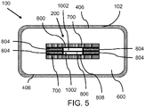
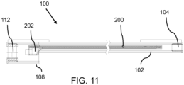
- the parametric disturbance sensor 100 includes a stripline enclosure (102) having an internal chamber (110), a stripline sensor core (200) positioned within the internal chamber, a fill material (600) filling the internal chamber (110), and a cable-end connector (202) connected to the stripline sensor core (200) for connecting the stripline sensor core (200) to a processing unit (not shown).
- the fill material (600) fills the internal chamber (110) such that the stripline sensor core (200) is not in direct contact with the stripline enclosure (102).
- FIG. 3 depicts a perspective view of a stripline enclosure of an example embodiment parametric disturbance sensor.
- the stripline enclosure 102 has an internal chamber 110.
- the stripline enclosure 102 encloses and protects, at least in part, a stripline sensor core 200.
- the stripline enclosure 102 also distributes, at least in part, a force exerted on the parametric disturbance sensor 100. For example, once a force is exerted on the stripline enclosure 102 the force is distributed, at least in part, over the stripline enclosure 102 on which the force is exerted. Examples of this force distribution include, but is not limited to, an elastic deformation or an elastic compression of the stripline enclosure 102.
- the stripline enclosure 102 should be sufficiently resilient for use in a traffic monitoring system.
- the stripline enclosure 102 is made of a steel tube (SAE 4130 chromium-molybdenum, SAE 304 stainless steel, or any other grade of steel suitable for such an application).
- SAE 4130 chromium-molybdenum, SAE 304 stainless steel, or any other grade of steel suitable for such an application A skilled person would understand that other materials could be used without departing from the scope of this disclosure. For instance, it may be appropriate to use different steel alloys depending on the environmental conditions. An example would be to use a more corrosion-resistant steel alloy for the stripline enclosure 102 when deploying the sensor in high salt and moisture environments (such as northern Canada and the US).
- the parametric disturbance sensor 100 may also be enclosed in a protective layer (not shown) prior to being embedded in a roadway.
- This protective layer adds an additional layer of protection from the environment.
- protective layers include, but are not limited to, urethane, plastic, epoxy, tar, or any other material suitable for a protective layer.
- the dimensions of the stripline enclosure 102 may affect the sensitivity of the parametric disturbance sensor 100.
- the materials, width, and thickness of the sensor enclosure 102 may also be used to adjust the sensitivity of the parametric disturbance sensor 100.
- the ability of the stripline enclosure 102 to deflect depends, at least in part, on physical characteristics of the stripline enclosure 102 such as wall thickness or width.
- the wall thickness and/or width of the stripline enclosure 102 the deflection characteristics of the parametric disturbance sensor 100 can be modified. This will alter the sensitivity of the parametric disturbance sensor 100 when compared with another parametric disturbance sensor 100 using a stripline enclosure 102 having a different wall thickness.
- the parametric disturbance sensor 100 may also have a cable end enclosure 108.
- the cable end enclosure 108 is connected to an end of the stripline enclosure 102 and is used to enclose, at least in part, the cable end connector 202.
- the cable end enclosure 108 may be attached, at least in part, to the stripline enclosure 102.
- the cable end enclosure 108 may be affixed to the stripline enclosure 102 via a weld, a solder, an adhesive, or a mechanical attachment means such as screws, rivets, folds, crimps, or clips.
- a weld a weld
- a solder a solder
- an adhesive a mechanical attachment means
- a mechanical attachment means such as screws, rivets, folds, crimps, or clips.
- the cable end enclosure 108 might be riveted to the sensor enclosure 102.
- the cable end enclosure 108 and the stripline enclosure 102 may be constructed as a single unit.
- the stripline enclosure 102 could be constructed so as to leave sufficient room to enclose, at least in part, the cable end enclosure 108.
- the parametric disturbance sensor 100 has a cable-end connector 202.
- the cable end connector 202 is configured to connect the stripline sensor core 200 to a processing unit. This allows information to be transported from the stripline sensor core 200 to the processing unit.
- the processing unit is, at least partially, for processing ETDR signals.
- a coaxial RF connector such as a SMA or SMB connector may be used as a cable end connector.
- a coaxial RF connector such as a SMA or SMB connector may be used as a cable end connector.
- SMA or SMB connector may be used as a coaxial RF connector.
- SMC or other suitable connector may also be used without departing from the scope of this disclosure.
- the cable end enclosure further includes a cable end cap 112.
- the cable end cap 112 acts as a cover for an open end of the cable end enclosure 108.
- the cable end cap 112 prevents dirt, environmental debris, and/or moisture from entering the cable end enclosure 108 by covering, at least in part, the cable end enclosure 108. This helps to protect the cable end connector 202 and any other components within the cable end enclosure 108 from environmental exposure and damage.
- the stripline enclosure 102 has an end cap 104.
- the end cap 104 is positioned at the end of the stripline enclosure 102 that is opposite the cable end enclosure 108.
- the end cap 104 is configured to seal the stripline enclosure 102 at one end so that once the parametric disturbance sensor 100 is filled the fill material 600 does not exit the stripline enclosure 102.
- the end cap also prevents debris and moisture, at least in part, from entering the stripline enclosure 102.
- the end cap 104 is attached to the stripline enclosure 102 using any suitable means.
- the end cap 104 is welded to the stripline enclosure 102.
- a skilled person would understand that alternate methods of attaching the end cap 104 to the stripline enclosure 102 can be used without departing from the scope of this disclosure.
- the end cap 104 can be press-fit into the stripline enclosure.
- the end cap 104 can be glued, soldered, or clipped into the stripline enclosure 102.
- the end cap 104 should be sufficiently resilient for use in a traffic monitoring environment.
- the end cap 104 is aluminum.
- Other suitable materials can be used without departing from the scope of this disclosure.
- a plastic, rubber, or steel alloy end cap 104 could also be used.
- a stripline sensor core (200) is positioned within the internal chamber.
- the stripline sensor core 200 is configured to generate, at least in part, an impedance change once a force is exerted on the parametric disturbance sensor 100.
- the stripline sensor core 200 is configured to generate, at least in part, an impedance change once a force is exerted on the sensor core 200.
- the stripline sensor core 200 is approximately centered in the stripline enclosure 102. It should be noted, however, that the stripline sensor core 200 can be positioned anywhere within the stripline enclosure 102, including contacting an inner wall of an internal chamber of the stripline enclosure 102.
- the parametric disturbance sensor 100 also includes a fill material 600.
- the fill material 600 fills the internal chamber 110 of the stripline enclosure 102 so that the stripline sensor core 200 does not move within the internal chamber 110 of the stripline enclosure 102. Or, the stripline sensor core 200 is stabilized within the internal chamber 110.
- the fill material also mechanically transmits and/or connects, at least in part, a force applied to the stripline enclosure 102 to the stripline sensor core 200.
- the fill material may also used to electrically isolate the stripline sensor core 200 from the stripline enclosure 102.
- the stripline sensor core 200 may be electrically connected to the stripline enclosure 102. It may be beneficial to connect the stripline enclosure 102 electrically to the ground planes 800 and 808 for shielding the sensor core 200 electrically from any radio frequency (RF) interference. Also, although the risk of static charge buildup in the sensor core 200 is low because the sensor core 200 may be encapsulated within the filler material, the risk of static charge buildup would be about zero if the stripline enclosure 102 is electrically connected to the ground planes 800 and 808 for grounding.
- RF radio frequency
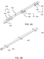
- FIG. 4A a stripline sensor core 200 and positioning blocks 404 of an example embodiment parametric disturbance sensor 100 are depicted.
- one or more positioning blocks 404 are configured to position the stripline sensor core 200 within the internal chamber 110.
- the one or more positioning blocks 404 are in contact with both the stripline sensor core 200 and an inner wall 406 of the internal chamber 110.
- the positioning blocks 404 may also be used to prevent the stripline sensor core 200 from directly contacting the inner wall 406 of the internal chamber 110.
- the positioning blocks 404 include horizontal positioning blocks 402 and vertical positioning blocks 400.
- the vertical positioning blocks 400 are used to position the stripline sensor core 200 along a vertical axis in the internal chamber 110 of the stripline enclosure 102.
- the horizontal positioning blocks 402 are used to position the stripline sensor core 200 along a horizontal axis in the internal chamber 110 of the stripline enclosure 102.
- the horizontal positioning blocks 402 contact the inner wall of the internal chamber 110 of the stripline enclosure 102 so that the sensor can be positioned along a horizontal axis of the internal chamber 110 of the stripline enclosure 102.
- a spring steel positioning block is configured to span a horizontal axis of internal chamber 110 of the stripline enclosure 102.
- the spring steel positioning block is also glued to the stripline sensor core 200 so that the stripline sensor core 200 is approximately horizontally centered in the internal chamber 110 of the stripline enclosure 102.
- the vertical positioning blocks 400 contact opposing inner walls of the internal chamber 110 of the stripline enclosure 102 so that the sensor can be positioned along a vertical axis of the internal chamber 110.
- a urethane positioning block is configured to span a vertical axis of internal chamber 110.
- the urethane positioning block is also glued to the stripline sensor core 200 so that the stripline sensor core 200 is approximately vertically centered in the internal chamber 110.
- the horizontal positioning blocks 402 are made with spring steel.
- the vertical positioning blocks 400 are made with urethane.
- rubber could be used as a horizontal positioning block 402, vertical positioning block 400, or both.
- the positioning blocks (404) are attached to the stripline sensor core (200).
- both the horizontal positioning blocks 402 and the vertical positioning blocks 400 are attached to the stripline sensor core 200.
- the vertical positioning blocks 400 and horizontal positioning blocks 402 are glued to the stripline sensor core 200.
- the positioning blocks 404 may be welded or soldered onto the stripline sensor core 200.
- the positioning blocks 404 may be mechanically attached to the stripline sensor core 200 using screws, clips, rivets, friction fit, or similar fastening means.
- a stripline sensor core 200 and positioning blocks 404 of an alternate example parametric disturbance sensor 100 are depicted.
- the positioning blocks 404 are configured to position the sensor both vertically and horizontally in the internal chamber of the stripline enclosure. That is, the positioning block 404 performs the function of both the verticall positioning block 400 and horizontal positioning block 402 could also be combined to form a block or strip that would position the sensor both vertically and horizontally.
- the stripline sensor core 200 might be enclosed in a wrapping or webbing that is configured to position, at least in part, the stripline sensor core 200.
- the fill material 600 is configured to fill the internal chamber 110 of the stripline enclosure 102 so that a force applied to the stripline enclosure 102 is mechanically transferred, at least in part, to the stripline sensor core 200.
- the fill material 600 may be selected to cooperate with the input dynamic range of the analog electronics and the output of the stripline sensor core 200. As the fill material 600 expands or contracts due to environmental factors, the fill material 600 exerts a varying amount of pressure on the stripline sensor core 200 and the stripline enclosure 102. This change in pressure being exerted on the stripline sensor core 200 and the stripline enclosure 102 affects the output of the sensor core 200.
- the analog electronics would also have to be configured to match this change in output range for the stripline sensor core 200. If the dynamic range of the input of the analog electronics is not correctly tuned to account for the variable pressure exerted by the fill material 600 on the stripline sensor core 600 under varying environmental conditions, then the output of the stripline sensor core 200 may not be properly received. That is, the sensor will be providing a signal response outside of the dynamic range of the analog electronics.
- a parametric disturbance sensor 100 with the analog electronics configured to have a dynamic range of 47-53 ohms.
- the output of the compressed stripline sensor core 200 may drop below 45 ohms. Once this occurs, the signal response of the stripline sensor core 200 no longer matches the tuning of the analog electronics. Although the stripline sensor core 200 is still responsive to the load, the resulting signal output from the stripline sensor core 200 would be below 45 ohms and is outside the dynamic range of the analog electronics.
- the fill material 600 may exert more pressure or less pressure on the stripline sensor core 200 depending on the fill material's properties or environmental factors or both.
- the dynamic range of the input of the analog electronics may be tuned to account for the output range of the stripline sensor core 200 when variable pressure is exerted on the stripline sensor core 200 by the fill material 600.
- the fill material 600 is selected for various reasons as described below.
- the fill material 600 may be selected so that high environmental temperatures will not cause the fill material 600 to expand and cause an undue deformation of the stripline sensor core 200. That is, the fill material 600 should have a sufficiently low thermal expansion coefficient so that high temperatures frequently found in vehicular measurement systems will not cause the fill material 600 to expand and cause an undue deformation of the stripline sensor core 200.
- the fill material 600 may also be selected so that the output of the sensor remains constant despite change in environmental factors such as temperature.
- the fill material 600 may also have a low enough viscosity so that the fill material is able to flow into empty spaces defined in the internal chamber 110 of the stripline enclosure 102. This will help to ensure that any forces applied on the stripline enclosure 102 will be transferred, at least in part and via the fill material 600, to the stripline sensor core 200.
- the fill material 600 is a urethane mix comprising a mixture of urethane and silica sand.
- the urethane mix is sufficiently viscous so as to fill any empty space in the internal chamber 110 of the stripline enclosure 102.
- the thermal properties of silica sand allow for a tuning of the thermal properties of the urethane mix so that high temperatures would not cause an undue deformation of the stripline sensor core 200.
- the fill material 600 may be configured to harden over time to become a solid.
- the fill material 600 may initially be in a fluid state when poured into the internal chamber 110 then allowed to harden to a solid.
- examples of such fill materials include epoxies, plastics, urethanes, silicones, and curable plastics.
- the base impedance of the parametric disturbance sensor 100 can be adjusted, at least in part, by adjusting the pressure of the fill material 600 once the stripline enclosure 102 is filled with fill material 600.
- the pressure of the fill material 600 in the stripline enclosure 102 pre-loads, at least in part, the stripline sensor core 200.
- the pre-loaded stripline sensor core 200 would then have a baseline impedance once the parametric disturbance sensor 100 is finally assembled.
- An example method of setting a base impedance of the parametric disturbance sensor 100 is provided.
- it is a method of manufacturing a parametric disturbance sensor.
- the stripline sensor core 200 is positioned in a stripline enclosure 102 and is connected, via the cable end connector 202 and cable 106, to a processing device that displays the impedance value of the stripline sensor core 200.
- a pressurized fill material 600 is injected into the internal cavity 110 of the stripline enclosure 102, the impedance of the stripline sensor core 200 changes and is displayed via the processing device.
- a desired baseline impedance value is reached the injection of the fill material 600 into the internal cavity 110 is stopped.
- the fill material is cured, that is, the fill material 600 transitions from a liquid to a solid.
- An example of a desired baseline impedance value is 50 ohms.
- the stripline sensor core may be positioned in the center of the internal cavity 110. In another embodiment, the stripline sensor core may also be positioned near a force receiving side of the stripline enclosure. In another embodiment, the stripline sensor core may be positioned in contact with a force receiving side of the stripline enclosure.
- the stripline sensor core 200 includes a first ground plane 800, a second ground plane 808, and a center trace 806.
- the stripline sensor core 200 is a flat planar shape.
- the stripline sensor core 200 is a flat planar rectangular shape.
- the center trace 806, the first ground plane 800, and the second ground plane 808 of the stripline sensor core are substantially parallel to each other.
- a force receiving side of the stripline enclosure, the center trace 806, the first ground plane 800, and the second ground plane 808 of the stripline sensor core are substantially parallel to each other.
- a force receiving side of the stripline enclosure is configured to receive a force.
- the force receiving side of the stripline enclosure is the side of the stripline enclosure that is closest to a surface of a roadway. It will be appreciated that any side of the stripline enclosure closest to an applied force can be considered a force receiving side of a stripline enclosure.
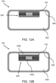
- FIG. 12A and FIG. 12B illustrate an example of the above embodiment.
- the stripline sensor core 200 is configured to detect, at least in part, a force exerted on the parametric disturbance sensor.
- a force is transmitted, at least in part, from the stripline enclosure 102 to the stripline sensor core 200 through the fill 600. This force deforms, at least in part, the first ground plane 800, second ground plane 808, or both.
- an electrical signal is transmitted to the unloaded parametric disturbance sensor 100.
- the parametric disturbance sensor 100 has a baseline impedance.
- the deformation of the first ground plane 800, second ground plane 808, or both changes the impedance of the parametric disturbance sensor 100. This changes the electrical signal. This change in electrical signal is then used to determine characteristics of the force applied to the parametric disturbance sensor 100.
- the first ground plane 800, second ground plane 808, and center trace 806 are electrically connected.
- the first ground plane 800, second ground plane 808, and the center trace 806 are electrically connected by the cable-end connector 202 at one end, and using a pin, wire, or similar electrical connection at the opposite end. Once the first ground plane 800, second ground plane 808, and the center trace 806 are electrically connected, an electrical circuit is formed.
- the center trace 806 is electrically separated from the ground planes (800 and 808) at the end away from the cable end using a resistor which matches the impedance of the electrical circuit. For example, a 50 ohm resistor. In this embodiment, it is a requirement for the ETDR equipment or ETDR processing unit, and may be different if we had different ETDR equipment or ETDR processing unit.
- the center trace 806 was directly connected to the ground planes (800 and 808) in a short circuit configuration; the center trace 806 was not connected to ground planes (800 and 808) at all in an open circuit configuration; and, the center trace was connected to the ground planes (800 and 808) by a resistor of a selected resistance.
- the first ground plane 800 and second ground plane 808 are supported and separated from the and center trace 806, at least in part, using printed circuit boards (PCBs).
- PCBs printed circuit boards
- the first ground plane PCB 802, second ground plane PCB 810, first ground plane cable end PCB 811, and second ground plane cable end PCB 812 are used to mechanically support and separate, at least in part, the first ground plane 800 and the second ground plane 808 from the center trace 806.
- the ground plane PCBs also act as spacers and are not deformable. The ground plane PCBs are not deformable for not breaking the solder joints.
- PCBs may also be used to electrically connect, at least in part, the first ground plane 800, second ground plane 808, and the center trace 806.
- first ground plane 800 is electrically connected to a first ground plane PCB 802.
- second ground plane 808 is electrically connected to a second ground plane PCB 810.
- the center trace 806 is configured to contact, at least in part, the first ground plane PCB 802 and the second ground plane PCB 810. Once the first ground plane PCB 802 and second ground plane PCB 810 are connected the first ground plane 800, second ground plane 808, and center trace 806 are electrically connected.
- first ground plane PCB 802 and the second ground plane PCB 810 are connected by soldering the first ground plane PCB 802 and the second ground plane PCB 810 together.
- first ground plane PCB 802 and the second ground plane PCB 810 can be contemplated.
- the two PCBs could be attached by welding or using an adhesive, clips, screws, bolts, or other attachment means.
- the center trace 806 is separated from the first ground plane 800 and the second ground plane 808 by one or more separators 804.
- the separators 804 are configured to separate the first ground plane 800 and the second ground plane 808 from the center trace 806.
- the separators 804 are further configured to isolate the center trace 806 from the first ground plane 800 and the second ground plane 808. This isolation can be either physical, electrical, or both.
- the separators 804 are made of an electrically insulating foam such as a polyethylene closed-cell foam.
- an electrically insulating foam such as a polyethylene closed-cell foam.
- other materials could be used as a separator 804 without departing from the scope of this disclosure.
- rubber, plastic, or other suitable materials could be used as a separator 804.
- the spacer 804 between the center trace 806 and the two ground planes (800 and 808) may be chosen for a few reasons including rebound, dimensional tolerance, and loss tangent. Although, solid materials (rather than foam) including rubber and silicone result in a functioning embodiment, the attenuation may be too high to be acceptable. Also, in another embodiment, using a foam as a separator 804 on the whole ground plane surface resulted in a functioning embodiment although the attenuation may be too high to be acceptable.
- the sensor core 200 with an air gap 1002 is a preferred embodiment.
- one moving ground plane e.g. the ground plane 800 deflects towards the center trace 806 and one ground plane (e.g. the ground plane 808) at a fixed distance, resulted in a functioning embodiment although the sensitivity may not be as regular as desired.
- the closed cell foam as a separator 804 has a loss tangent similar to air, which is preferable.
- the closed cell foam as a separator 804 may be selected to rebound well when compressed.
- the closed cell foam may also be selected for precise dimensional tolerances.
- the base impedance of the sensor 100 can be tuned according to the invention, at least in part, by adjusting a distance between a first ground plane 800 and a second ground plane 808 to the center trace 806 of the sensor core 200.
- the distance between a first ground plane 800 and a second ground plane 808 to the center trace 806 can be adjusted by varying the height of the separators 804 between the center trace 806 and the first ground plane 800, the second ground plane 808, or both.
- the base impedance of the sensor 100 can be tuned, at least in part, by adjusting the width of the center trace 806 of the stripline sensor core 200. That is, the characteristic impedance of the sensor can be increased or decreased by decreasing or increasing the width of the electrically conductive portion of the center trace 806.
- adjusting the base impedance of the sensor 100 include, but are not limited to, adjusting the distance between the copper center trace 806 and the ground planes (800 and 808) by the foam height 804, the width of copper ground planes (800 and 808), and/or the width and/or height of the air gap 1002.
- the width of the air gap 1002 is adjusted by the width of the center trace 806, the width of the foam/separator 804, and the and the overall width of the stripline sensor core 200.
- the overall width of the stripline sensor core 200 is defined by the width of the center trace PCB, the width of the first ground plane PCB, and the width of the second ground plane PCB.
- the impedance of the sensor changes from the baseline impedance. This change in impedance is then used to determine certain properties of the load being exerted on the parametric disturbance sensor 100.
- Properties of the load being exerted on the parametric disturbance sensor 100 include, but are not limited to, the location of the load on the sensor, the pressure of the load on the sensor, the width of the load on the sensor, and the center of the load on the sensor. Additional information can include the number of axles, weight per axle, weight per wheel, vehicle weight, wheel count, wheel spacing, axle spacing, inter-axle spacing, axle width, and axle and/or vehicle speed. Aggregate information may also be collected such as the total number of vehicles detected by the sensors. In an embodiment, both the first ground plane 800 and the second ground plane 808 deform or deflect towards the center trace 806 on the application of a force on the sensor core 200.
- the change in impedance, deflection of the sensor core, or signal generated can vary in size (amplitude) depending on a variety of factors that can be adjusted, at least in part, when constructing the sensor core 200. These include, but are not limited to, the position of the sensor core stiffeners 700 on or in the sensor core 200, deflection properties of the sensor core 200, stripline enclosure 102 deflection properties, the position of the sensor core 200 in the stripline enclosure 102, and the type of fill material 600 used. By adjusting these parameters the signal size of the signal can be tuned.
- the consistency of the signal can be controlled and/or adjusted if so desired. This can be done in a variety of ways including, but not limited to, the consistency of the materials being used to build the sensor core 200, the stripline enclosure 102, the fill material 600, and, positioning of the sensor core 200 within the stripline enclosure 102. In an embodiment, the consistency of the signal is controlled or adjusted so the consistency is maximized.
- the attenuation of the signal down the length of the sensor core 200 can be controlled, at least in part, by adjusting the height and width of the air gap 1002 between the first ground plane 800, the second ground plane 808, and the center trace 806.
- the height distance between the ground planes (800 and 808) and the center trace 806 is adjust by adjusting the separator 804 height.
- the width of the air gap 1002 is adjusted by the width of the center trace 806, the width of the foam/separator 804, and the overall width of the stripline sensor core 200.
- the overall width of the stripline sensor core 200 is defined by the width of the center trace PCB, the width of the first ground plane PCB, and the width of the second ground plane PCB.
- the longevity of the signal emitted from the sensor core 200 can also be adjusted, at least in part. This can be done by adjusting the amount the sensor core 200 deflects (as a percentage of its height, for example), adjusting the amount of the deflection of the enclosure 102, adjusting the type of fill material 600 used, and/or selecting the materials used as a separator 804. In an embodiment, the longevity of the signal may be adjusted to minimize or maximize signal longevity as required by the ETDR equipment or ETDR processing unit.
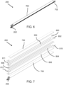
- the stripline sensor core 200 includes one or more sensor core stiffeners 700.
- the sensor core stiffeners 700 are used to stiffen the sensor core 200 for maintaining stability of the sensor core 200 during the manufacturing process. Also, the sensor core stiffeners 700 transfer, at least in part, a force on the sensor core 200 once a force is exerted, at least in part, on the sensor core stiffeners 700.
- the sensor core stiffeners 700 are configured adjacent to a first ground plane 800 of the stripline sensor core 200.
- a second sensor core stiffener is configured adjacent to a second ground plane 808 of the stripline sensor core 200.
- the sensor core stiffeners 700 are configured to stiffen the sensor core 200 and thereby reduce the sensor core's 200 tendency to flex and/or twist.
- the sensor core stiffeners (700) have a similar size and shape to the sensor core 200.
- the sensor core stiffeners 700 are strips made of spring steel.
- a force exerted on the stripline enclosure 102 may be transmitted, at least in part, via the fill material 600 to the sensor core stiffeners 700.
- the sensor core stiffeners 700 then distribute, at least in part, the force to the sensor core 200.
- This force distribution may manifest itself in a variety of ways, including a deformation, flex, or compression of the sensor core stiffener 700.
- the sensor core stiffener 700 may also be configured to absorb, at least in part, the force exerted on the sensor core 200. Thus, the sensor core stiffener 700 may be used to protect, at least in part, the sensor core 200 from excessive compression or other excessive forces, thereby preventing damage to the sensor core 200.
- the amount of force absorbed and transferred by the sensor core stiffeners 700 will depend on the shape of the sensor core stiffeners and the materials used, among other factors. For instance, the amount of force absorbed and distributed by a spring steel core stiffener may differ from a strip aluminum core stiffener, a line-shaped aluminum core stiffener, or a cylindrical stainless steel core stiffener.
- sensor core stiffeners 700 could be used for the sensor core stiffeners 700 without departing from the scope of this disclosure.
- a line-shaped aluminum core stiffener or a cylindrical stainless steel core stiffener running along the length of the stripline sensor core 200 may also be used without departing from the scope of this disclosure.
- the sensor core is sufficiently resilient so as to not require the addition of sensor core stiffeners 700.
- a wrap (not shown) is provided.
- the wrap surrounds the stripline sensor core 200.
- the wrap is configured to prevent the fill material 600 from entering the stripline sensor core 200.
- the wrap is applied to the sensor core 200 before the positioning block 400, the sensor core stiffener 700, or both, are applied.
- the positioning blocks 400 and the sensor core 200 may be wrapped together.
- the sensor core 200 and the sensor core stiffener is wrapped together.
- the wrap material used should be suitably resilient so that fill material 600 (and other environmental debris) will not enter the sensor core 200 once the internal chamber 110 of the stripline enclosure 102 is filled with fill material 600.
- the wrap material should also be sufficiently flexible so as to provide little to no space between the sensor core 200 (and/or positioning block 400 and/or sensor core stiffener 700) and the wrap.
- a heat shrink is used as a wrap.
- the sensor core 200 and optionally the sensor core stiffener 700 and/or positioning block 400 are wrapped in a heat shrink material. Heat is then applied to the heat shrink, causing the heat wrap to shrink around the sensor core 200, sensor core stiffener 700, and/or positioning block 400 assembly.
- FIG. 8A depicts a representative top down view of a vehicle having a wheel 900 and an axle 902 crossing over a parametric disturbance sensor 100 embedded in a road 904.
- FIG. 8B depicts a representative front view cross section (along the plane marked B-B in FIG. 8A ) of the vehicle of FIG. 8A crossing over a parametric disturbance sensor 100 embedded in a road 904.
- a parametric disturbance sensor as disclosed is a part of a vehicle monitoring system.
- vehicle monitoring system examples include, but are not limited to, a weigh in motion (WIM) system.
- WIM weigh in motion
- the parametric disturbance sensor 100 is embedded in a road 904.
- the parametric disturbance sensor 100 is electrically connected to a processing unit, in this example a vehicle monitoring system, through the cable 106.
- a force 906 is exerted on the parametric disturbance sensor 100.
- the force 906 is exerted, approximately, across an area represented by the contact patch 908.
- the force 906 causes the parametric disturbance sensor 100, and in particular the stripline sensor core 200, to be elastically deformed. This elastic deformation causes the impedance of the parametric disturbance sensor 100 to change from its baseline impedance.
- the force 906 is transferred, at least in part, from the stripline enclosure 102 to the stripline sensor core 200 through the fill material 600.
- the fill material 600 is sufficiently resilient so as to transfer the force, at least in part, from a contact patch 906 on the stripline enclosure 102 (i.e., the wheel contact point) to an area on the stripline sensor core 200 that is approximately in-line and parallel with the contact patch 908 on the stripline enslocure 102.
- the force 906 exerted on the localized area of the stripline sensor core 200 deforms the stripline sensor core 200. This deformation causes the impedance of the stripline sensor core 200 to change from its baseline impedance at that localized area.
- EDR electrical time domain reflectometry
- This information can then be used to determine properties of the force 906 exerted on the parametric disturbance sensor 100. These properties include, but are not limited to, the number of axles, weight per axle, weight per wheel, vehicle weight, wheel count, wheel spacing, axle spacing, wheel width, inter-axle spacing, axle width, and axle and/or vehicle speed.
- the vehicle monitoring system may also collect aggregate information. This can include, but is not limited to, the total number of vehicles detected by the sensors.
- the parametric disturbance sensor 100 includes a coating that adds additional protection from the environment. This is useful in environments where salt, water, snow, moisture, dirt, etc., is prevalent.
- the coating can be applied using any known method including, but not limited to wrapping, dipping, spraying, painting, etc.
- FIG. 9 in this example embodiment a parametric disturbance sensor 100 having a stripline sensor core 200 and a fill material 600 surrounding the stripline sensor core 200 is depicted.
- the parametric disturbance sensor 100 is embedded directly in the road 904.
- the parametric disturbance sensor 100 in this alternate example embodiment is embedded in a trench, cut space, carved space, moulded space, or any other space in the road 904 so that the parametric disturbance sensor 100 is approximately flush, at least in part, with the road 904.
- the road 906 itself acts, at least in part, as an enclosure for the stripline sensor core 200.
- the fill material 600 directly contacts the road 904 such that the road 904 acts as a replacement for the bottom, sides, and ends of the stripline enclosure.
- the fill material 600 is left exposed at the top so that a load (e.g., from a wheel of a vehicle) is applied directly to the fill material 600 of the parametric disturbance sensor 100.
- the exposed top of the parametric disturbance sensor 100 may be covered. Examples of a covering include, but are not limited to, any one or a combination of a steel plate, a roadway paving material, gravel, aggregate, sand, or any other material suitable for use in a roadway.
- the stripline sensor core 200 is embedded directly in the road 904 without a fill material 600 surrounding the stripline sensor core 200. Then, the parametric disturbance sensor 100 is fixed in the space in the road by a roadway fill material (not illustrated) such as, for example, a roadway paving material, grout, concrete, or asphalt. In another embodiment, the fill material and the roadway fill material may be the same material.
- one or more positioning blocks 404 may also be used to position the stripline sensor core 200 in the space in the road 904. Once the stripline sensor core 200 is positioned in the space in the road 904, the fill material 600 is applied so that the fill material 600 fills the space in the road 904 and covers, at least in part, the stripline sensor core 200.
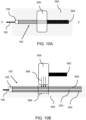
- FIG. 10A depicts a representative top down view of a vehicle having a wheel 900 and an axle 902 crossing over a parametric disturbance sensor 100 embedded in a road 904.
- FIG. 10B depicts a representative front view cross section (along the plane marked C-C in FIG. 10A ) of the vehicle of FIG. 10A crossing over a parametric disturbance sensor 100 embedded in a road 904.
- the operation of the parametric disturbance sensor 100 as depicted in FIG. 10A and 10B is substantially similar to the operation previously described in FIG. 8A and 8B .
- the difference is that as the wheel 900 rolls over the parametric disturbance sensor 100 the force 906 is applied directly to the fill material 600, the roadway fill material, and/or the covering. The force 906 is then transmitted to the stripline sensor core 200 as previously described.
- the stripline sensor core 200 is attached to an interior wall of the stripline enclosure 102. That is, the stripline sensor core 200 is directly attached to the interior wall of the stripline enclosure 102.
- the fill material 600 fills the internal chamber of the stripline enclosure 102 so that the fill material 600 surrounds the sides of the stripline sensor core 200 that are not attached to the stripline enclosure 102.
- the fill material will transmit, at least in part, any forces exerted on the of the stripline enclosure 102 to the stripline sensor core 200.
- the stripline sensor core 200 is attached to the stripline enclosure 102 using an adhesive layer 1000.
- the adhesive layer 1000 is used to attach the stripline sensor core 200 to an interior wall of the stripline enclosure 102.
- the adhesive layer 1000 is attached to a top surface of the stripline sensor core 200 and extends the length of the stripline sensor core 200. Generally, however, the adhesive layer 1000 will be between a surface of the stripline sensor core 200 and an inner wall of the interior chamber of the stripline enclosure 102.
- the adhesive layer 1000 can be applied to any appropriate surface of the stripline sensor core 200.
- the adhesive layer 1000 is attached to a ground plane 800 of the stripline sensor core 200, then the stripline sensor core 200 and adhesive are attached to the interior wall of the stripline enclosure 102.
- the adhesive layer 1000 is applied to another surface of the stripline sensor core 200 such as the sensor core stiffener 700.
- the adhesive layer 1000 can be applied to the any part of, or the entirety of, a surface of the stripline sensor core 200.
- the adhesive layer 1000 is at least as wide as the stripline sensor core 200.
- the adhesive layer 1000 is continuous and also at least as long as the stripline sensor core 200.
- the adhesive layer can include one or more adhesive strip segments (not shown) applied anywhere along the stripline sensor core 200.
- the adhesive strip segments can be sized in any suitable manner.
- the stripline sensor core 200 is attached to the stripline enclosure 102 using two or more adhesive strip segments that are half as wide as the stripline sensor core 200 and 1/10 th the length of the stripline sensor core.
- Other configurations of adhesive strip segments can be used as necessary.
- the fill material 600 will fill any voids or spaces defined by the stripline sensor core 200, the adhesive strip segments (not shown), and the stripline enclosure 102.
- the adhesive layer 1000 is configured to mechanically transmit, at least in part, forces exerted on the stripline enclosure 102 to the stripline sensor core 200.
- the adhesive layer 1000 is an electrical insulator that electrically isolates the stripline sensor core 200 from the stripline enclosure 102.
- the adhesive layer can be any material suitable for attaching the stripline sensor core 200 to the interior wall of the stripline enclosure 102.
- these materials include, but are not limited to, a two-sided acrylic adhesive, a heat activated adhesive (e.g., 3M THERMOBOND FILM), glue, epoxy, etc.
- the positioning block is attached to the stripline sensor core.
- the stripline enclosure is a groove defined in a roadway.
- the intermediate attachment layer is an adhesive.
- a preferred sensor core comprises: a center trace; a first ground plane separated from the center trace by a first seperator; a second ground plane separated from the center trace by a second separator; and a cable-end connector connected to the center trace for connecting the sensor core to a processing unit.
Landscapes
- Physics & Mathematics (AREA)
- General Physics & Mathematics (AREA)
- Engineering & Computer Science (AREA)
- General Engineering & Computer Science (AREA)
- Architecture (AREA)
- Civil Engineering (AREA)
- Structural Engineering (AREA)
- Chemical & Material Sciences (AREA)
- Analytical Chemistry (AREA)
- Force Measurement Appropriate To Specific Purposes (AREA)
Description
- Intelligent transportation systems may involve data collection, toll collection, vehicle classification, weigh in motion (WIM), and other traffic monitoring or traffic management systems.
- For example, WIM systems are used to detect and weigh vehicles in motion in order to enhance the operation of road systems in a safer and more efficient manner.
- A WIM system uses one or more sensors to obtain information about a vehicle as it is sensed by the sensor, typically as the vehicle moves over the sensor. Some information may be measured directly from a sensor, and other information may be measured and derived from a combination of sensors operating together.
- Generally, time domain reflectometry (TDR) is a measurement technique based on the principle that a transmission line of a particular geometry presents a known characteristic impedance. Therefore, changes to the geometry of the transmission line result in changes in the characteristic impedance that can be measured using TDR techniques. A skilled person would understand that time domain reflectometry may be used with optical or electrical signals, and that practically the optical and electrical signals are physically different requiring differently skilled knowledge and equipment to measure changes in transmission line characteristics.
- In an electrical transmission line, a reflection will be generated whenever an incident wave meets a change in the characteristic impedance, which is also known as a discontinuity. TDR measurement techniques can then be used to determine the location and magnitude of the discontinuity in the transmission line from the reflected wave. Thus, the time the reflected wave takes to travel back along the transmission line can be translated into a distance along the transmission line. The magnitude of the voltage of the reflected wave can be used to calculate the amount of change in the characteristic impedance.
- TDR measurement techniques may use a step input voltage for the incident wave shape as it eases the complexity of interpreting the reflected signals. In source- or both-ends terminated transmission lines, the step input voltage is divided between the source impedance and the transmission line impedance. If the source and transmission line impedances are matched, then the voltage measured between the source and the transmission line over the round-trip of the incident wave along the transmission line is half of the step input voltage. Where discontinuities exist on the transmission line, the voltage measured will deviate from exactly half due to the received reflections. Other approaches for TDR measurement may also be used, such as wave modulation with a swept frequency.
- UK patent application
GB 2,250,813A US2016/018252A andUS4799381A also disclose parametric disturbance sensors used for weigh in motion applications. - The invention consists of a parametric disturbance sensor as defined in
claim 1 and a method of its manufacturing as defined in claim 14. The parametric disturbance sensor uses Electrical Time Domain Reflectometry measurement techniques. The parametric disturbance sensor is configured to be used in a weigh in motion (WIM) system and VEHICLE INFORMATION IN MOTION system. - Vehicle information that may be measured includes, for example, the number of axles, weight per axle, weight per wheel, wheel width, vehicle weight, wheel count, wheel spacing, axle spacing, inter-axle spacing, axle width, and axle and/or vehicle speed. Aggregate information may also be collected such as the total number of vehicles detected by the sensors.
- In an aspect, the parametric disturbance sensor is resistant to environmental contaminants such as moisture, dirt, or road debris. The parametric disturbance sensor uses few moving parts and is resistant to mechanical damage. The baseline impedance of the parametric disturbance sensor may be tuned simply and in a variety of ways during the manufacturing process. The parametric disturbance sensor is straightforward to manufacture.
- In another aspect, the sensor core comprises, a center trace, a first ground plane separated from the center trace by a first separator, a second ground plane separated from the center trace by a second separator, and, a cable-end connector connected to the center trace for connecting the sensor core to a processing unit. In various embodiments, the separators are elastically deformable, electrically insulating foam, and/or a closed cell foam with a loss tangent similar to air.
- What is provided is a Parametric Disturbance Sensor. The parametric disturbance sensor has a stripline enclosure that defines an internal chamber. A stripline sensor core is positioned within the internal chamber. A fill material is used to fill the internal chamber. Furthermore, a cable-end connector is connected to the stripline sensor core for connecting the stripline sensor core to a processing unit.
- A method for manufacturing a parametric disturbance sensor is provided. The method includes positioning a stripline sensor core within an internal chamber of a stripline enclosure. A first end of the internal chamber is then sealed. A fill material is used to fill the internal chamber.
- A sensor core is also provided. The sensor core includes a center trace. A first ground plane is separated from the center trace by a first seperator, and a second ground plane separated from the center trace by a second separator. A cable-end connector is connected to the center trace for connecting the sensor core to a processing unit.
- Other aspects are identified in the claims.
- Other aspects and features of the non-limiting embodiments may now become apparent to those skilled in the art upon review of the following detailed description of the non-limiting embodiments with the accompanying drawings.
-
-
FIG. 1 [PAGE 1/10] depicts a perspective view of an example parametric disturbance sensor. -
FIG. 2 [PAGE 1/10] depicts a cross-sectional view of the parametric disturbance sensor ofFIG. 1 -
FIG. 3 [PAGE 2/10] depicts a perspective view of a stripline enclosure of an example parametric disturbance sensor. -
FIG. 4A [PAGE 3/10] depicts a perspective view of a stripline sensor core and positioning blocks of an example parametric disturbance sensor. -
FIG. 4B [PAGE 3/10] depicts a perspective view of a stripline sensor core and positioning blocks of another example parametric disturbance sensor. -
FIG. 5 [PAGE 4/10] depicts a cross sectional view alongFIG. 1 line A-A showing a stripline enclosure, a stripline sensor core, and a fill material of an example embodiment parametric disturbance sensor. -
FIG. 6 [PAGE 5/10] depicts a perspective view of a stripline sensor core of an example embodiment parametric disturbance sensor. -
FIG. 7 [PAGE 5/10] depicts an exploded perspective view of the stripline sensor core ofFIG. 6 . -
FIG. 8A [PAGE 6/10] depicts a representative top down view of a vehicle having a wheel and an axle crossing over a parametric disturbance sensor embedded in a road. -
FIG. 8B [PAGE 6/10] depicts a representative front view cross section (along the plane marked B-B inFIG. 8A ) of the vehicle ofFIG. 8A crossing over a parametric disturbance sensor embedded in a road. -
FIG. 9 [PAGE 7/10] depicts a cross sectional view of an alternate embodiment of a parametric disturbance sensor showing a stripline sensor core and a fill material embedded in a roadway. -
FIG. 10A [PAGE 8/10] depicts a representative top down view of a vehicle having a wheel and an axle crossing over the parametric disturbance sensor ofFIG. 9 embedded in a road. -
FIG. 10B [PAGE 8/10] depicts a representative front view cross section (along the plane marked C-C inFIG. 10A ) of the vehicle ofFIG. 10A crossing over a parametric disturbance sensor embedded in a road. -
FIG. 11 [PAGE 9/10] depicts a cross-sectional view of another embodiment of the parametric disturbance sensor. -
FIG. 12A [PAGE 10/10] depicts a cross sectional view of the embodiment of the parametric disturbance sensor ofFIG. 11 . -
FIG. 12B [PAGE 10/10] depicts a cross sectional view of the embodiment of the parametric disturbance sensor. - The drawings are not necessarily to scale and may be illustrated by phantom lines, diagrammatic representations and fragmentary views. In certain instances, details unnecessary for an understanding of the embodiments (and/or details that render other details difficult to perceive) may have been omitted.
- Corresponding reference characters indicate corresponding components throughout the several figures of the drawings. Elements in the several figures are illustrated for simplicity and clarity and have not been drawn to scale. The dimensions of some of the elements in the figures may be emphasized relative to other elements for facilitating an understanding of the various disclosed embodiments. In addition, common, but well-understood, elements that are useful or necessary in commercially feasible embodiments are often not depicted to provide a less obstructed view of the embodiments of the present disclosure.
-
- 100 -
- Parametric Disturbance Sensor
- 102 -
- Stripline Enclosure
- 104 -
- End Cap
- 106 -
- Cable
- 108 -
- Cable End Enclosure
- 110 -
- internal chamber
- 112 -
- Cable End Enclosure cap
- 200 -
- Stripline Sensor Core
- 202 -
- Cable End Connector
- 400 -
- Vertical Positioning Blocks
- 402 -
- Horizontal Positioning Blocks
- 404 -
- Positioning Blocks
- 406 -
- Inner wall of the internal chamber
- 600 -
- Fill material
- 700 -
- Sensor Core Stiffener
- 702 -
- Far End Connection
- 800 -
- First Ground Plane
- 802 -
- First Ground Plane PCB
- 804 -
- Separators/Foam
- 806 -
- Center Trace
- 808 -
- Second Ground Plane
- 810 -
- Second Ground Plane PCB
- 811 -
- First Ground Plane Cable End PCB
- 812 -
- Second Ground Plane Cable End PCB
- 900 -
- Wheel
- 902 -
- Axle
- 904 -
- Road
- 906 -
- Force
- 908 -
- Contact patch/area below contact patch
- 1000 -
- Adhesive/Adhesive Layer
- 1002 -
- Air Gap
- The following detailed description is merely exemplary and is not intended to limit the described embodiments or the application and uses of the described embodiments. As used, the word "exemplary" or "illustrative" means "serving as an example, instance, or illustration." Any implementation described as "exemplary" or "illustrative" is not necessarily to be construed as preferred or advantageous over other implementations. All of the implementations described below are exemplary implementations provided to enable persons skilled in the art to make or use the embodiments of the disclosure and are not intended to limit the scope of the disclosure. The scope of the invention is defined by the claims. For the description, the terms "upper," "lower," "left," "rear," "right," "front," "vertical," "horizontal," and derivatives thereof shall relate to the examples as oriented in the drawings. There is no intention to be bound by any expressed or implied theory in the preceding Technical Field, Background, Summary or the following detailed description. It is also to be understood that the devices and processes illustrated in the attached drawings, and described in the following specification, are exemplary embodiments (examples), aspects and/or concepts defined in the appended claims. Hence, dimensions and other physical characteristics relating to the embodiments disclosed are not to be considered as limiting, unless the claims expressly state otherwise. It is understood that the phrase "at least one" is equivalent to "a". The aspects (examples, alterations, modifications, options, variations, embodiments and any equivalent thereof) are described regarding the drawings. It should be understood that the invention is limited to the subject matter provided by the claims, and that the invention is not limited to the particular aspects depicted and described.
-
FIG. 1 depicts a perspective view of an example embodiment parametric disturbance sensor.FIG. 2 depicts a cross-sectional view of the parametric disturbance sensor ofFIG. 1 . - In accordance with an embodiment, the
parametric disturbance sensor 100 includes a stripline enclosure (102) having an internal chamber (110), a stripline sensor core (200) positioned within the internal chamber, a fill material (600) filling the internal chamber (110), and a cable-end connector (202) connected to the stripline sensor core (200) for connecting the stripline sensor core (200) to a processing unit (not shown). In another embodiment, the fill material (600) fills the internal chamber (110) such that the stripline sensor core (200) is not in direct contact with the stripline enclosure (102). -
FIG. 3 depicts a perspective view of a stripline enclosure of an example embodiment parametric disturbance sensor. - In accordance with an embodiment, the
stripline enclosure 102 has aninternal chamber 110. Thestripline enclosure 102 encloses and protects, at least in part, astripline sensor core 200. Thestripline enclosure 102 also distributes, at least in part, a force exerted on theparametric disturbance sensor 100. For example, once a force is exerted on thestripline enclosure 102 the force is distributed, at least in part, over thestripline enclosure 102 on which the force is exerted. Examples of this force distribution include, but is not limited to, an elastic deformation or an elastic compression of thestripline enclosure 102. - The
stripline enclosure 102 should be sufficiently resilient for use in a traffic monitoring system. In an example embodiment thestripline enclosure 102 is made of a steel tube (SAE 4130 chromium-molybdenum, SAE 304 stainless steel, or any other grade of steel suitable for such an application). A skilled person would understand that other materials could be used without departing from the scope of this disclosure. For instance, it may be appropriate to use different steel alloys depending on the environmental conditions. An example would be to use a more corrosion-resistant steel alloy for thestripline enclosure 102 when deploying the sensor in high salt and moisture environments (such as northern Canada and the US). - In some embodiments the
parametric disturbance sensor 100 may also be enclosed in a protective layer (not shown) prior to being embedded in a roadway. This protective layer adds an additional layer of protection from the environment. Examples of protective layers include, but are not limited to, urethane, plastic, epoxy, tar, or any other material suitable for a protective layer. - It should be noted that the dimensions of the
stripline enclosure 102 may affect the sensitivity of theparametric disturbance sensor 100. In accordance with an embodiment, the materials, width, and thickness of thesensor enclosure 102 may also be used to adjust the sensitivity of theparametric disturbance sensor 100. For instance, in this example the ability of thestripline enclosure 102 to deflect depends, at least in part, on physical characteristics of thestripline enclosure 102 such as wall thickness or width. By adjusting the wall thickness and/or width of thestripline enclosure 102 the deflection characteristics of theparametric disturbance sensor 100 can be modified. This will alter the sensitivity of theparametric disturbance sensor 100 when compared with anotherparametric disturbance sensor 100 using astripline enclosure 102 having a different wall thickness. - Referring again to
FIG. 1, FIG. 2 , andFIG. 3 , in accordance with an embodiment theparametric disturbance sensor 100 may also have acable end enclosure 108. Thecable end enclosure 108 is connected to an end of thestripline enclosure 102 and is used to enclose, at least in part, thecable end connector 202. - In some example embodiments the
cable end enclosure 108 may be attached, at least in part, to thestripline enclosure 102. For example, thecable end enclosure 108 may be affixed to thestripline enclosure 102 via a weld, a solder, an adhesive, or a mechanical attachment means such as screws, rivets, folds, crimps, or clips. A skilled person would understand that other ways of attaching thecable end enclosure 108 to thestripline enclosure 102 may be contemplated without straying from the scope of this disclosure. For instance, thecable end enclosure 108 might be riveted to thesensor enclosure 102. - In another example embodiment the
cable end enclosure 108 and thestripline enclosure 102 may be constructed as a single unit. For example, thestripline enclosure 102 could be constructed so as to leave sufficient room to enclose, at least in part, thecable end enclosure 108. - Referring now to
FIG. 2 ,FIG. 4A, and FIG. 4B , in accordance with an embodiment theparametric disturbance sensor 100 has a cable-end connector 202. Thecable end connector 202 is configured to connect thestripline sensor core 200 to a processing unit. This allows information to be transported from thestripline sensor core 200 to the processing unit. The processing unit is, at least partially, for processing ETDR signals. - In an example embodiment, a coaxial RF connector such as a SMA or SMB connector may be used as a cable end connector. A skilled person would understand that other connectors could be used that would be within the scope of this disclosure. For example, a SMC or other suitable connector may also be used without departing from the scope of this disclosure.
- Referring again to
FIG. 1 and FIG. 2 , in accordance with an embodiment the cable end enclosure further includes acable end cap 112. Thecable end cap 112 acts as a cover for an open end of thecable end enclosure 108. Thecable end cap 112 prevents dirt, environmental debris, and/or moisture from entering thecable end enclosure 108 by covering, at least in part, thecable end enclosure 108. This helps to protect thecable end connector 202 and any other components within thecable end enclosure 108 from environmental exposure and damage. - Referring again to
FIG. 1 , thestripline enclosure 102 has anend cap 104. Theend cap 104 is positioned at the end of thestripline enclosure 102 that is opposite thecable end enclosure 108. Theend cap 104 is configured to seal thestripline enclosure 102 at one end so that once theparametric disturbance sensor 100 is filled thefill material 600 does not exit thestripline enclosure 102. The end cap also prevents debris and moisture, at least in part, from entering thestripline enclosure 102. - The
end cap 104 is attached to thestripline enclosure 102 using any suitable means. In the example provided inFIG. 1 , theend cap 104 is welded to thestripline enclosure 102. A skilled person would understand that alternate methods of attaching theend cap 104 to thestripline enclosure 102 can be used without departing from the scope of this disclosure. For instance, theend cap 104 can be press-fit into the stripline enclosure. Alternately, theend cap 104 can be glued, soldered, or clipped into thestripline enclosure 102. - The
end cap 104 should be sufficiently resilient for use in a traffic monitoring environment. In one example embodiment, theend cap 104 is aluminum. Other suitable materials can be used without departing from the scope of this disclosure. For example, a plastic, rubber, or steelalloy end cap 104 could also be used. - Referring again to
FIG. 2 andFIG. 3 , a stripline sensor core (200) is positioned within the internal chamber. Thestripline sensor core 200 is configured to generate, at least in part, an impedance change once a force is exerted on theparametric disturbance sensor 100. In another embodiment, thestripline sensor core 200 is configured to generate, at least in part, an impedance change once a force is exerted on thesensor core 200. - In the example embodiment depicted in
FIG. 2 , thestripline sensor core 200 is approximately centered in thestripline enclosure 102. It should be noted, however, that thestripline sensor core 200 can be positioned anywhere within thestripline enclosure 102, including contacting an inner wall of an internal chamber of thestripline enclosure 102. - The
parametric disturbance sensor 100 also includes afill material 600. Thefill material 600 fills theinternal chamber 110 of thestripline enclosure 102 so that thestripline sensor core 200 does not move within theinternal chamber 110 of thestripline enclosure 102. Or, thestripline sensor core 200 is stabilized within theinternal chamber 110. - In an embodiment, the fill material also mechanically transmits and/or connects, at least in part, a force applied to the
stripline enclosure 102 to thestripline sensor core 200. - In an embodiment, the fill material may also used to electrically isolate the
stripline sensor core 200 from thestripline enclosure 102. - In another embodiment, the
stripline sensor core 200 may be electrically connected to thestripline enclosure 102. It may be beneficial to connect thestripline enclosure 102 electrically to the ground planes 800 and 808 for shielding thesensor core 200 electrically from any radio frequency (RF) interference. Also, although the risk of static charge buildup in thesensor core 200 is low because thesensor core 200 may be encapsulated within the filler material, the risk of static charge buildup would be about zero if thestripline enclosure 102 is electrically connected to the ground planes 800 and 808 for grounding. - Referring now to
FIG. 4A , astripline sensor core 200 andpositioning blocks 404 of an example embodimentparametric disturbance sensor 100 are depicted. - Generally, one or more positioning blocks 404 are configured to position the
stripline sensor core 200 within theinternal chamber 110. In this embodiment, the one or more positioning blocks 404 are in contact with both thestripline sensor core 200 and aninner wall 406 of theinternal chamber 110. The positioning blocks 404 may also be used to prevent thestripline sensor core 200 from directly contacting theinner wall 406 of theinternal chamber 110. - In the example depicted in
FIG. 4A , the positioning blocks 404 include horizontal positioning blocks 402 and vertical positioning blocks 400. The vertical positioning blocks 400 are used to position thestripline sensor core 200 along a vertical axis in theinternal chamber 110 of thestripline enclosure 102. The horizontal positioning blocks 402 are used to position thestripline sensor core 200 along a horizontal axis in theinternal chamber 110 of thestripline enclosure 102. - The horizontal positioning blocks 402 contact the inner wall of the
internal chamber 110 of thestripline enclosure 102 so that the sensor can be positioned along a horizontal axis of theinternal chamber 110 of thestripline enclosure 102. In an example embodiment, a spring steel positioning block is configured to span a horizontal axis ofinternal chamber 110 of thestripline enclosure 102. The spring steel positioning block is also glued to thestripline sensor core 200 so that thestripline sensor core 200 is approximately horizontally centered in theinternal chamber 110 of thestripline enclosure 102. - The vertical positioning blocks 400 contact opposing inner walls of the
internal chamber 110 of thestripline enclosure 102 so that the sensor can be positioned along a vertical axis of theinternal chamber 110. In an example embodiment, a urethane positioning block is configured to span a vertical axis ofinternal chamber 110. The urethane positioning block is also glued to thestripline sensor core 200 so that thestripline sensor core 200 is approximately vertically centered in theinternal chamber 110. - In the example embodiments provided above the horizontal positioning blocks 402 are made with spring steel. The vertical positioning blocks 400 are made with urethane. A skilled person, however, would understand that any suitable material could be used as a
horizontal positioning block 402 or avertical positioning block 400 without departing from the scope of this disclosure. For example, rubber could be used as ahorizontal positioning block 402,vertical positioning block 400, or both. - Referring again to
FIG. 4A , in the example depicted inFIG. 4A the positioning blocks (404) are attached to the stripline sensor core (200). - In this example both the horizontal positioning blocks 402 and the vertical positioning blocks 400 are attached to the
stripline sensor core 200. In an example embodiment, the vertical positioning blocks 400 and horizontal positioning blocks 402 are glued to thestripline sensor core 200. A skilled person would understand that other ways of attaching the vertical positioning blocks 400 and horizontal positioning blocks 402 may be contemplated without departing from the scope of this disclosure. For instance, the positioning blocks 404 may be welded or soldered onto thestripline sensor core 200. Alternately, the positioning blocks 404 may be mechanically attached to thestripline sensor core 200 using screws, clips, rivets, friction fit, or similar fastening means. - Referring now to
FIG. 4B , astripline sensor core 200 andpositioning blocks 404 of an alternate exampleparametric disturbance sensor 100 are depicted. In this example the positioning blocks 404 are configured to position the sensor both vertically and horizontally in the internal chamber of the stripline enclosure. That is, thepositioning block 404 performs the function of both theverticall positioning block 400 andhorizontal positioning block 402 could also be combined to form a block or strip that would position the sensor both vertically and horizontally. - Alternate ways of positioning the
stripline sensor core 200 can be contemplated without departing from the scope of disclosure. For example, thestripline sensor core 200 might be enclosed in a wrapping or webbing that is configured to position, at least in part, thestripline sensor core 200. - Referring now to
FIG. 5 , thefill material 600 is configured to fill theinternal chamber 110 of thestripline enclosure 102 so that a force applied to thestripline enclosure 102 is mechanically transferred, at least in part, to thestripline sensor core 200. - The
fill material 600 may be selected to cooperate with the input dynamic range of the analog electronics and the output of thestripline sensor core 200. As thefill material 600 expands or contracts due to environmental factors, thefill material 600 exerts a varying amount of pressure on thestripline sensor core 200 and thestripline enclosure 102. This change in pressure being exerted on thestripline sensor core 200 and thestripline enclosure 102 affects the output of thesensor core 200. - In this case, the analog electronics would also have to be configured to match this change in output range for the
stripline sensor core 200. If the dynamic range of the input of the analog electronics is not correctly tuned to account for the variable pressure exerted by thefill material 600 on thestripline sensor core 600 under varying environmental conditions, then the output of thestripline sensor core 200 may not be properly received. That is, the sensor will be providing a signal response outside of the dynamic range of the analog electronics. - For example, in an embodiment, consider a
parametric disturbance sensor 100 with the analog electronics configured to have a dynamic range of 47-53 ohms. In this example, once thefill material 600 expands due to heat, the output of the compressedstripline sensor core 200 may drop below 45 ohms. Once this occurs, the signal response of thestripline sensor core 200 no longer matches the tuning of the analog electronics. Although thestripline sensor core 200 is still responsive to the load, the resulting signal output from thestripline sensor core 200 would be below 45 ohms and is outside the dynamic range of the analog electronics. It is understood that thefill material 600 may exert more pressure or less pressure on thestripline sensor core 200 depending on the fill material's properties or environmental factors or both. - In an embodiment, the dynamic range of the input of the analog electronics may be tuned to account for the output range of the
stripline sensor core 200 when variable pressure is exerted on thestripline sensor core 200 by thefill material 600. In another embodiment, thefill material 600 is selected for various reasons as described below. - The
fill material 600 may be selected so that high environmental temperatures will not cause thefill material 600 to expand and cause an undue deformation of thestripline sensor core 200. That is, thefill material 600 should have a sufficiently low thermal expansion coefficient so that high temperatures frequently found in vehicular measurement systems will not cause thefill material 600 to expand and cause an undue deformation of thestripline sensor core 200. - The
fill material 600 may also be selected so that the output of the sensor remains constant despite change in environmental factors such as temperature. - The
fill material 600 may also have a low enough viscosity so that the fill material is able to flow into empty spaces defined in theinternal chamber 110 of thestripline enclosure 102. This will help to ensure that any forces applied on thestripline enclosure 102 will be transferred, at least in part and via thefill material 600, to thestripline sensor core 200. - In an example embodiment the
fill material 600 is a urethane mix comprising a mixture of urethane and silica sand. In this example embodiment, the urethane mix is sufficiently viscous so as to fill any empty space in theinternal chamber 110 of thestripline enclosure 102. Furthermore, the thermal properties of silica sand allow for a tuning of the thermal properties of the urethane mix so that high temperatures would not cause an undue deformation of thestripline sensor core 200. - In other example embodiments the
fill material 600 may be configured to harden over time to become a solid. For instance, thefill material 600 may initially be in a fluid state when poured into theinternal chamber 110 then allowed to harden to a solid. Examples of such fill materials include epoxies, plastics, urethanes, silicones, and curable plastics. - According to the invention, the base impedance of the
parametric disturbance sensor 100 can be adjusted, at least in part, by adjusting the pressure of thefill material 600 once thestripline enclosure 102 is filled withfill material 600. The pressure of thefill material 600 in thestripline enclosure 102 pre-loads, at least in part, thestripline sensor core 200. The pre-loadedstripline sensor core 200 would then have a baseline impedance once theparametric disturbance sensor 100 is finally assembled. - An example method of setting a base impedance of the
parametric disturbance sensor 100 is provided. In another embodiment, it is a method of manufacturing a parametric disturbance sensor. In this method, thestripline sensor core 200 is positioned in astripline enclosure 102 and is connected, via thecable end connector 202 andcable 106, to a processing device that displays the impedance value of thestripline sensor core 200. As apressurized fill material 600 is injected into theinternal cavity 110 of thestripline enclosure 102, the impedance of thestripline sensor core 200 changes and is displayed via the processing device. Once a desired baseline impedance value is reached the injection of thefill material 600 into theinternal cavity 110 is stopped. Then, the fill material is cured, that is, thefill material 600 transitions from a liquid to a solid. An example of a desired baseline impedance value is 50 ohms. - In an embodiment, the stripline sensor core may be positioned in the center of the
internal cavity 110. In another embodiment, the stripline sensor core may also be positioned near a force receiving side of the stripline enclosure. In another embodiment, the stripline sensor core may be positioned in contact with a force receiving side of the stripline enclosure. - Referring now to
FIG. 6 and FIG. 7 , an example embodiment of a stripline sensor core is depicted. Thestripline sensor core 200 includes afirst ground plane 800, asecond ground plane 808, and acenter trace 806. In an embodiment, thestripline sensor core 200 is a flat planar shape. In another embodiment, thestripline sensor core 200 is a flat planar rectangular shape. In another embodiment, thecenter trace 806, thefirst ground plane 800, and thesecond ground plane 808 of the stripline sensor core are substantially parallel to each other. In another embodiment, a force receiving side of the stripline enclosure, thecenter trace 806, thefirst ground plane 800, and thesecond ground plane 808 of the stripline sensor core are substantially parallel to each other. - It will be appreciated that a force receiving side of the stripline enclosure is configured to receive a force. In the embodiment where the
parametric disturbance sensor 100 is embedded in a roadway, the force receiving side of the stripline enclosure is the side of the stripline enclosure that is closest to a surface of a roadway. It will be appreciated that any side of the stripline enclosure closest to an applied force can be considered a force receiving side of a stripline enclosure.FIG. 12A and FIG. 12B illustrate an example of the above embodiment. - The
stripline sensor core 200 is configured to detect, at least in part, a force exerted on the parametric disturbance sensor. In the example provided inFIG. 6 and FIG. 7 , a force is transmitted, at least in part, from thestripline enclosure 102 to thestripline sensor core 200 through thefill 600. This force deforms, at least in part, thefirst ground plane 800,second ground plane 808, or both. - In this example embodiment, an electrical signal is transmitted to the unloaded
parametric disturbance sensor 100. Theparametric disturbance sensor 100 has a baseline impedance. As a force is exerted on theparametric disturbance sensor 100, the deformation of thefirst ground plane 800,second ground plane 808, or both changes the impedance of theparametric disturbance sensor 100. This changes the electrical signal. This change in electrical signal is then used to determine characteristics of the force applied to theparametric disturbance sensor 100. - In the example depicted in
FIG. 6 and FIG. 7 , thefirst ground plane 800,second ground plane 808, andcenter trace 806 are electrically connected. In some example embodiments, thefirst ground plane 800,second ground plane 808, and thecenter trace 806 are electrically connected by the cable-end connector 202 at one end, and using a pin, wire, or similar electrical connection at the opposite end. Once thefirst ground plane 800,second ground plane 808, and thecenter trace 806 are electrically connected, an electrical circuit is formed. - In an embodiment, the
center trace 806 is electrically separated from the ground planes (800 and 808) at the end away from the cable end using a resistor which matches the impedance of the electrical circuit. For example, a 50 ohm resistor. In this embodiment, it is a requirement for the ETDR equipment or ETDR processing unit, and may be different if we had different ETDR equipment or ETDR processing unit. In other embodiments, it is possible to create asensor core 200 whereby: thecenter trace 806 was directly connected to the ground planes (800 and 808) in a short circuit configuration; thecenter trace 806 was not connected to ground planes (800 and 808) at all in an open circuit configuration; and, the center trace was connected to the ground planes (800 and 808) by a resistor of a selected resistance. - In the example depicted in
FIG. 6 and FIG. 7 , thefirst ground plane 800 andsecond ground plane 808 are supported and separated from the andcenter trace 806, at least in part, using printed circuit boards (PCBs). In these examples, the firstground plane PCB 802, secondground plane PCB 810, first ground planecable end PCB 811, and second ground planecable end PCB 812 are used to mechanically support and separate, at least in part, thefirst ground plane 800 and thesecond ground plane 808 from thecenter trace 806. In the above example, the ground plane PCBs also act as spacers and are not deformable. The ground plane PCBs are not deformable for not breaking the solder joints. - In other example embodiments, PCBs may also be used to electrically connect, at least in part, the
first ground plane 800,second ground plane 808, and thecenter trace 806. In this example, thefirst ground plane 800 is electrically connected to a firstground plane PCB 802. Similarly, thesecond ground plane 808 is electrically connected to a secondground plane PCB 810. - The
center trace 806 is configured to contact, at least in part, the firstground plane PCB 802 and the secondground plane PCB 810. Once the firstground plane PCB 802 and secondground plane PCB 810 are connected thefirst ground plane 800,second ground plane 808, andcenter trace 806 are electrically connected. - In this example embodiment, the first
ground plane PCB 802 and the secondground plane PCB 810 are connected by soldering the firstground plane PCB 802 and the secondground plane PCB 810 together. A skilled person would understand that alternative ways of connecting the firstground plane PCB 802 and the secondground plane PCB 810 can be contemplated. For example, the two PCBs could be attached by welding or using an adhesive, clips, screws, bolts, or other attachment means. - In the example provided in
FIG. 7 thecenter trace 806 is separated from thefirst ground plane 800 and thesecond ground plane 808 by one ormore separators 804. Theseparators 804 are configured to separate thefirst ground plane 800 and thesecond ground plane 808 from thecenter trace 806. - The
separators 804 are further configured to isolate thecenter trace 806 from thefirst ground plane 800 and thesecond ground plane 808. This isolation can be either physical, electrical, or both. - In the example provided in
FIG. 7 , theseparators 804 are made of an electrically insulating foam such as a polyethylene closed-cell foam. A skilled person would understand that other materials could be used as aseparator 804 without departing from the scope of this disclosure. For instance, rubber, plastic, or other suitable materials could be used as aseparator 804. - The
spacer 804 between thecenter trace 806 and the two ground planes (800 and 808) may be chosen for a few reasons including rebound, dimensional tolerance, and loss tangent. Although, solid materials (rather than foam) including rubber and silicone result in a functioning embodiment, the attenuation may be too high to be acceptable. Also, in another embodiment, using a foam as aseparator 804 on the whole ground plane surface resulted in a functioning embodiment although the attenuation may be too high to be acceptable. Thesensor core 200 with anair gap 1002 is a preferred embodiment. - In another embodiment, one moving ground plane (e.g. the
ground plane 800 deflects towards the center trace 806) and one ground plane (e.g. the ground plane 808) at a fixed distance, resulted in a functioning embodiment although the sensitivity may not be as regular as desired. The closed cell foam as aseparator 804 has a loss tangent similar to air, which is preferable. The closed cell foam as aseparator 804 may be selected to rebound well when compressed. The closed cell foam may also be selected for precise dimensional tolerances. - The base impedance of the
sensor 100 can be tuned according to the invention, at least in part, by adjusting a distance between afirst ground plane 800 and asecond ground plane 808 to thecenter trace 806 of thesensor core 200. In the example provided inFIG. 6 and FIG. 7 , the distance between afirst ground plane 800 and asecond ground plane 808 to thecenter trace 806 can be adjusted by varying the height of theseparators 804 between thecenter trace 806 and thefirst ground plane 800, thesecond ground plane 808, or both. - In another example embodiment, the base impedance of the
sensor 100 can be tuned, at least in part, by adjusting the width of thecenter trace 806 of thestripline sensor core 200. That is, the characteristic impedance of the sensor can be increased or decreased by decreasing or increasing the width of the electrically conductive portion of thecenter trace 806. - Other ways of adjusting the base impedance of the
sensor 100 include, but are not limited to, adjusting the distance between thecopper center trace 806 and the ground planes (800 and 808) by thefoam height 804, the width of copper ground planes (800 and 808), and/or the width and/or height of theair gap 1002. The width of theair gap 1002 is adjusted by the width of thecenter trace 806, the width of the foam/separator 804, and the and the overall width of thestripline sensor core 200. In an embodiment, the overall width of thestripline sensor core 200 is defined by the width of the center trace PCB, the width of the first ground plane PCB, and the width of the second ground plane PCB. - As the
first ground plane 800,second ground plane 808, or both, deforms on the application of a force on theparametric disturbance sensor 100, the impedance of the sensor changes from the baseline impedance. This change in impedance is then used to determine certain properties of the load being exerted on theparametric disturbance sensor 100. Properties of the load being exerted on theparametric disturbance sensor 100 include, but are not limited to, the location of the load on the sensor, the pressure of the load on the sensor, the width of the load on the sensor, and the center of the load on the sensor. Additional information can include the number of axles, weight per axle, weight per wheel, vehicle weight, wheel count, wheel spacing, axle spacing, inter-axle spacing, axle width, and axle and/or vehicle speed. Aggregate information may also be collected such as the total number of vehicles detected by the sensors. In an embodiment, both thefirst ground plane 800 and thesecond ground plane 808 deform or deflect towards thecenter trace 806 on the application of a force on thesensor core 200. - The change in impedance, deflection of the sensor core, or signal generated, can vary in size (amplitude) depending on a variety of factors that can be adjusted, at least in part, when constructing the
sensor core 200. These include, but are not limited to, the position of thesensor core stiffeners 700 on or in thesensor core 200, deflection properties of thesensor core 200,stripline enclosure 102 deflection properties, the position of thesensor core 200 in thestripline enclosure 102, and the type offill material 600 used. By adjusting these parameters the signal size of the signal can be tuned. - Similarly, the consistency of the signal can be controlled and/or adjusted if so desired. This can be done in a variety of ways including, but not limited to, the consistency of the materials being used to build the
sensor core 200, thestripline enclosure 102, thefill material 600, and, positioning of thesensor core 200 within thestripline enclosure 102. In an embodiment, the consistency of the signal is controlled or adjusted so the consistency is maximized. - The attenuation of the signal down the length of the
sensor core 200 can be controlled, at least in part, by adjusting the height and width of theair gap 1002 between thefirst ground plane 800, thesecond ground plane 808, and thecenter trace 806. The height distance between the ground planes (800 and 808) and thecenter trace 806 is adjust by adjusting theseparator 804 height. The width of theair gap 1002 is adjusted by the width of thecenter trace 806, the width of the foam/separator 804, and the overall width of thestripline sensor core 200. In an embodiment, the overall width of thestripline sensor core 200 is defined by the width of the center trace PCB, the width of the first ground plane PCB, and the width of the second ground plane PCB. - The longevity of the signal emitted from the
sensor core 200 can also be adjusted, at least in part. This can be done by adjusting the amount thesensor core 200 deflects (as a percentage of its height, for example), adjusting the amount of the deflection of theenclosure 102, adjusting the type offill material 600 used, and/or selecting the materials used as aseparator 804. In an embodiment, the longevity of the signal may be adjusted to minimize or maximize signal longevity as required by the ETDR equipment or ETDR processing unit. - Referring again to
FIG. 6 and FIG. 7 , thestripline sensor core 200 includes one or moresensor core stiffeners 700. Thesensor core stiffeners 700 are used to stiffen thesensor core 200 for maintaining stability of thesensor core 200 during the manufacturing process. Also, thesensor core stiffeners 700 transfer, at least in part, a force on thesensor core 200 once a force is exerted, at least in part, on thesensor core stiffeners 700. - In the example depicted in
FIG. 6 and FIG. 7 , thesensor core stiffeners 700 are configured adjacent to afirst ground plane 800 of thestripline sensor core 200. A second sensor core stiffener is configured adjacent to asecond ground plane 808 of thestripline sensor core 200. - The
sensor core stiffeners 700 are configured to stiffen thesensor core 200 and thereby reduce the sensor core's 200 tendency to flex and/or twist. In this example embodiment the sensor core stiffeners (700) have a similar size and shape to thesensor core 200. In this example, thesensor core stiffeners 700 are strips made of spring steel. - In the example depicted in
FIG. 6 and FIG. 7 , a force exerted on thestripline enclosure 102 may be transmitted, at least in part, via thefill material 600 to thesensor core stiffeners 700. Thesensor core stiffeners 700 then distribute, at least in part, the force to thesensor core 200. This force distribution may manifest itself in a variety of ways, including a deformation, flex, or compression of thesensor core stiffener 700. - The
sensor core stiffener 700 may also be configured to absorb, at least in part, the force exerted on thesensor core 200. Thus, thesensor core stiffener 700 may be used to protect, at least in part, thesensor core 200 from excessive compression or other excessive forces, thereby preventing damage to thesensor core 200. - The amount of force absorbed and transferred by the
sensor core stiffeners 700 will depend on the shape of the sensor core stiffeners and the materials used, among other factors. For instance, the amount of force absorbed and distributed by a spring steel core stiffener may differ from a strip aluminum core stiffener, a line-shaped aluminum core stiffener, or a cylindrical stainless steel core stiffener. - A skilled person would understand that alternate shapes or materials could be used for the
sensor core stiffeners 700 without departing from the scope of this disclosure. For instance, a line-shaped aluminum core stiffener or a cylindrical stainless steel core stiffener running along the length of thestripline sensor core 200 may also be used without departing from the scope of this disclosure. - Furthermore, in another embodiment the sensor core is sufficiently resilient so as to not require the addition of
sensor core stiffeners 700. - In another example embodiment, a wrap (not shown) is provided. The wrap surrounds the
stripline sensor core 200. The wrap is configured to prevent thefill material 600 from entering thestripline sensor core 200. - In some example embodiments the wrap is applied to the
sensor core 200 before thepositioning block 400, thesensor core stiffener 700, or both, are applied. In another example embodiment the positioning blocks 400 and thesensor core 200 may be wrapped together. In yet another example embodiment, thesensor core 200 and the sensor core stiffener is wrapped together. - The wrap material used should be suitably resilient so that fill material 600 (and other environmental debris) will not enter the
sensor core 200 once theinternal chamber 110 of thestripline enclosure 102 is filled withfill material 600. The wrap material should also be sufficiently flexible so as to provide little to no space between the sensor core 200 (and/orpositioning block 400 and/or sensor core stiffener 700) and the wrap. - In an example embodiment a heat shrink is used as a wrap. In this example the
sensor core 200 and optionally thesensor core stiffener 700 and/orpositioning block 400 are wrapped in a heat shrink material. Heat is then applied to the heat shrink, causing the heat wrap to shrink around thesensor core 200,sensor core stiffener 700, and/orpositioning block 400 assembly. - A skilled person would understand that alternate materials could be used to wrap the
sensor core 200/sensor core stiffener 700/positioning block 400 assembly without departing from the scope of this disclosure. For example, a plastic film wrap, rubberized dip coating, or any other sealing wrap or dip material could also be used. - Referring now to
FIG. 8A and FIG. 8B , an example of how theparametric disturbance sensor 100 might be used in aroad 904 is provided.FIG. 8A depicts a representative top down view of a vehicle having awheel 900 and anaxle 902 crossing over aparametric disturbance sensor 100 embedded in aroad 904.FIG. 8B depicts a representative front view cross section (along the plane marked B-B inFIG. 8A ) of the vehicle ofFIG. 8A crossing over aparametric disturbance sensor 100 embedded in aroad 904. - In the example depicted in
FIG. 8A and FIG. 8B , a parametric disturbance sensor as disclosed is a part of a vehicle monitoring system. Examples of a vehicle monitoring system include, but are not limited to, a weigh in motion (WIM) system. - In this example the
parametric disturbance sensor 100 is embedded in aroad 904. Theparametric disturbance sensor 100 is electrically connected to a processing unit, in this example a vehicle monitoring system, through thecable 106. Once thewheel 900 contacts theparametric disturbance sensor 100, aforce 906 is exerted on theparametric disturbance sensor 100. Theforce 906 is exerted, approximately, across an area represented by thecontact patch 908. Theforce 906 causes theparametric disturbance sensor 100, and in particular thestripline sensor core 200, to be elastically deformed. This elastic deformation causes the impedance of theparametric disturbance sensor 100 to change from its baseline impedance. - In this example embodiment, the
force 906 is transferred, at least in part, from thestripline enclosure 102 to thestripline sensor core 200 through thefill material 600. In this example embodiment, thefill material 600 is sufficiently resilient so as to transfer the force, at least in part, from acontact patch 906 on the stripline enclosure 102 (i.e., the wheel contact point) to an area on thestripline sensor core 200 that is approximately in-line and parallel with thecontact patch 908 on thestripline enslocure 102. Theforce 906 exerted on the localized area of thestripline sensor core 200 deforms thestripline sensor core 200. This deformation causes the impedance of thestripline sensor core 200 to change from its baseline impedance at that localized area. - Using electrical time domain reflectometry (ETDR) principles, when an incident wave meets the change in the baseline impedance (or discontinuity), a reflected wave is generated. This reflected wave is then transmitted through the
cable 106 to the vehicle monitoring system. TDR techniques can then be used to then determine the magnitude and the location of the discontinuity from the reflected wave. - This information can then be used to determine properties of the
force 906 exerted on theparametric disturbance sensor 100. These properties include, but are not limited to, the number of axles, weight per axle, weight per wheel, vehicle weight, wheel count, wheel spacing, axle spacing, wheel width, inter-axle spacing, axle width, and axle and/or vehicle speed. The vehicle monitoring system may also collect aggregate information. This can include, but is not limited to, the total number of vehicles detected by the sensors. - In some embodiments the
parametric disturbance sensor 100 includes a coating that adds additional protection from the environment. This is useful in environments where salt, water, snow, moisture, dirt, etc., is prevalent. - The coating can be applied using any known method including, but not limited to wrapping, dipping, spraying, painting, etc.
- Referring now to
FIG. 9 ,10A, and 10B , an alternate example embodiment is disclosed. Referring now toFIG. 9 , in this example embodiment aparametric disturbance sensor 100 having astripline sensor core 200 and afill material 600 surrounding thestripline sensor core 200 is depicted. Theparametric disturbance sensor 100 is embedded directly in theroad 904. Theparametric disturbance sensor 100 in this alternate example embodiment is embedded in a trench, cut space, carved space, moulded space, or any other space in theroad 904 so that theparametric disturbance sensor 100 is approximately flush, at least in part, with theroad 904. - In this example, the
road 906 itself acts, at least in part, as an enclosure for thestripline sensor core 200. In the example depicted inFIG. 9 , thefill material 600 directly contacts theroad 904 such that theroad 904 acts as a replacement for the bottom, sides, and ends of the stripline enclosure. In this example embodiment, thefill material 600 is left exposed at the top so that a load (e.g., from a wheel of a vehicle) is applied directly to thefill material 600 of theparametric disturbance sensor 100. In another example embodiment, the exposed top of theparametric disturbance sensor 100 may be covered. Examples of a covering include, but are not limited to, any one or a combination of a steel plate, a roadway paving material, gravel, aggregate, sand, or any other material suitable for use in a roadway. - In another embodiment, the
stripline sensor core 200 is embedded directly in theroad 904 without afill material 600 surrounding thestripline sensor core 200. Then, theparametric disturbance sensor 100 is fixed in the space in the road by a roadway fill material (not illustrated) such as, for example, a roadway paving material, grout, concrete, or asphalt. In another embodiment, the fill material and the roadway fill material may be the same material. - In this example one or more positioning blocks 404 may also be used to position the
stripline sensor core 200 in the space in theroad 904. Once thestripline sensor core 200 is positioned in the space in theroad 904, thefill material 600 is applied so that thefill material 600 fills the space in theroad 904 and covers, at least in part, thestripline sensor core 200. - Referring now to
FIG. 10A and FIG. 10B , an example of how theparametric disturbance sensor 100 ofFIG. 9 might be used in aroad 904 is provided.FIG. 10A depicts a representative top down view of a vehicle having awheel 900 and anaxle 902 crossing over aparametric disturbance sensor 100 embedded in aroad 904.FIG. 10B depicts a representative front view cross section (along the plane marked C-C inFIG. 10A ) of the vehicle ofFIG. 10A crossing over aparametric disturbance sensor 100 embedded in aroad 904. - The operation of the
parametric disturbance sensor 100 as depicted inFIG. 10A and 10B is substantially similar to the operation previously described inFIG. 8A and 8B . The difference is that as thewheel 900 rolls over theparametric disturbance sensor 100 theforce 906 is applied directly to thefill material 600, the roadway fill material, and/or the covering. Theforce 906 is then transmitted to thestripline sensor core 200 as previously described. - Referring now to
FIG. 11 andFIG. 12A an alternateparametric disturbance sensor 100 is provided. In this example thestripline sensor core 200 is attached to an interior wall of thestripline enclosure 102. That is, thestripline sensor core 200 is directly attached to the interior wall of thestripline enclosure 102. - In the example depicted in
FIG. 11 andFIG. 12A , thefill material 600 fills the internal chamber of thestripline enclosure 102 so that thefill material 600 surrounds the sides of thestripline sensor core 200 that are not attached to thestripline enclosure 102. - Furthermore, it will be appreciated that in the example depicted in
FIG. 11 andFIG. 12A where thestripline sensor core 200 is attached to an inner wall of thestripline enclosure 102 that is closest to a surface of a road or surface, a force exerted on thestripline enclosure 102 will be transmitted directly to thestripline sensor core 200 rather than through thefill material 600. - In other embodiments where the
stripline sensor core 200 is attached to an inner wall that is not closest to the surface of a road or surface, the fill material will transmit, at least in part, any forces exerted on the of thestripline enclosure 102 to thestripline sensor core 200. - Referring now to
FIG. 12B an alternate example of theparametric disturbance sensor 100 is depicted. In this example thestripline sensor core 200 is attached to thestripline enclosure 102 using anadhesive layer 1000. Theadhesive layer 1000 is used to attach thestripline sensor core 200 to an interior wall of thestripline enclosure 102. - In this example the
adhesive layer 1000 is attached to a top surface of thestripline sensor core 200 and extends the length of thestripline sensor core 200. Generally, however, theadhesive layer 1000 will be between a surface of thestripline sensor core 200 and an inner wall of the interior chamber of thestripline enclosure 102. - It will be appreciated that the
adhesive layer 1000 can be applied to any appropriate surface of thestripline sensor core 200. For instance, in the case where thestripline sensor core 200 does not requiresensor core stiffeners 700, theadhesive layer 1000 is attached to aground plane 800 of thestripline sensor core 200, then thestripline sensor core 200 and adhesive are attached to the interior wall of thestripline enclosure 102. In other embodiments theadhesive layer 1000 is applied to another surface of thestripline sensor core 200 such as thesensor core stiffener 700. - Furthermore the
adhesive layer 1000 can be applied to the any part of, or the entirety of, a surface of thestripline sensor core 200. In the embodiment depicted inFIG. 12B theadhesive layer 1000 is at least as wide as thestripline sensor core 200. Theadhesive layer 1000 is continuous and also at least as long as thestripline sensor core 200. In other embodiments, however, the adhesive layer can include one or more adhesive strip segments (not shown) applied anywhere along thestripline sensor core 200. - The adhesive strip segments can be sized in any suitable manner. For instance, in some embodiments the
stripline sensor core 200 is attached to thestripline enclosure 102 using two or more adhesive strip segments that are half as wide as thestripline sensor core - It will be appreciated that in these embodiments the
fill material 600 will fill any voids or spaces defined by thestripline sensor core 200, the adhesive strip segments (not shown), and thestripline enclosure 102. - The
adhesive layer 1000 is configured to mechanically transmit, at least in part, forces exerted on thestripline enclosure 102 to thestripline sensor core 200. - In some embodiments the
adhesive layer 1000 is an electrical insulator that electrically isolates thestripline sensor core 200 from thestripline enclosure 102. - The adhesive layer can be any material suitable for attaching the
stripline sensor core 200 to the interior wall of thestripline enclosure 102. Examples of these materials include, but are not limited to, a two-sided acrylic adhesive, a heat activated adhesive (e.g., 3M THERMOBOND FILM), glue, epoxy, etc. - In a preferred Parametric Disturbance Sensor, the positioning block is attached to the stripline sensor core. In a preferred Parametric Disturbance Sensor, the stripline enclosure is a groove defined in a roadway. In a preferred Parametric Disturbance Sensor, the intermediate attachment layer is an adhesive. In a preferred method of manufacturing a parametric disturbance sensor of any one or a combination of the clauses in this paragraph comprising: positioning a stripline sensor core within an internal chamber of a stripline enclosure; sealing a first end of the internal chamber; and filling the internal chamber with a fill material. A preferred sensor core comprises: a center trace; a first ground plane separated from the center trace by a first seperator; a second ground plane separated from the center trace by a second separator; and a cable-end connector connected to the center trace for connecting the sensor core to a processing unit.
Claims (16)
- A Parametric Disturbance Sensor comprising:a stripline enclosure defining an internal chamber;a stripline sensor core positioned within the internal chamber;a fill material configured to fill the internal chamber; anda cable-end connector connected to the stripline sensor core for connecting the stripline sensor core to a processing unit;wherein the fill material is configured to mechanically transmits a load, at least in part, on the stripline enclosure to the stripline sensor core once the load is applied to the stripline enclosure; andwherein the stripline sensor core is configured to change an electrical transmission-line parameter in response to the reception of the load;characterized in that a base impedance of the parametric disturbance sensor is tuned, at least in part, by pre-loading the stripline sensor core by adjusting a pressure of the fill material when filling the internal chamber; and/or by adjusting a distance between a first ground plane and a second ground plane of the stripline sensor core from a center trace.
- The sensor of claim 1, wherein:
the stripline sensor core is positioned in the internal chamber so that the stripline sensor core is not in direct contact with an inner wall of the internal chamber. - The sensor of claim 1, wherein:
the stripline sensor core is attached to an inner wall of the internal chamber so that the load, at least in part, is mechanically transmitted from the stripline enclosure to the stripline sensor core through the inner wall. - The sensor of claim 3, wherein:
the stripline sensor core is attached to the inner wall of the internal chamber using an intermediate attachment layer so that the stripline sensor core is not in direct contact with the inner wall. - The sensor of any one of claims 1 to 4, wherein:
the stripline sensor core is electrically isolated from the stripline enclosure. - The sensor of any one of claims 1 to 5, comprising:
a positioning block configured to position the stripline sensor core within the internal chamber so that the stripline sensor core does not directly contact the inner wall of the internal chamber. - The sensor of any one of claims 1 to 6, comprising:
a sensor core stiffener configured adjacent to the first ground plane of the stripline sensor core and the second ground plane of the stripline sensor core, wherein the sensor core stiffener is configured to:stiffen the stripline sensor core, andspread, at least in part, the load on the stripline sensor core once the load is applied to the stripline sensor core. - The sensor of any one of claims 1 to 7, comprising:
a wrap, surrounding the stripline sensor core, configured to prevent the fill material from entering an interior of the stripline sensor core. - The sensor of any one of claims 1 to 8, wherein:
the stripline enclosure is a steel tube. - The sensor of any one of claims 1 to 9 wherein the stripline sensor core comprises:the center trace;the first ground plane separated from the center trace by a first separator;the second ground plane separated from the center trace by a second separator; andwherein
the cable-end connector is connected to the center. - The sensor of claim 10, wherein:
the first and second separator are elastically deformable. - The sensor of claim 10 or claim 11, wherein:
the first and second separator are an electrically insulating foam. - The sensor of any one of claims 10 to 12, wherein:
the first and second separator are a closed cell foam with a loss tangent similar to air. - A method of manufacturing the parametric disturbance sensor of any one of claims 1 to 13, the method comprising:positioning the stripline sensor core within the internal chamber;sealing the first end of the internal chamber; andfilling the internal chamber with the fill material.
- The method of claim 14, further comprising:
pre-loading the stripline sensor core by filling the internal chamber with the fill material so that the fill material exerts a force on the stripline sensor core. - The method of claim 14 or claim 15, further comprising:
attaching the stripline sensor core to an inner wall of the internal chamber using an adhesive.
Applications Claiming Priority (2)
| Application Number | Priority Date | Filing Date | Title |
|---|---|---|---|
| US201662406905P | 2016-10-11 | 2016-10-11 | |
| PCT/CA2017/051209 WO2018068138A1 (en) | 2016-10-11 | 2017-10-11 | Parametric disturbance sensor for a vehicular measurement system |
Publications (3)
| Publication Number | Publication Date |
|---|---|
| EP3526552A1 EP3526552A1 (en) | 2019-08-21 |
| EP3526552A4 EP3526552A4 (en) | 2020-06-17 |
| EP3526552B1 true EP3526552B1 (en) | 2023-03-22 |
Family
ID=61905038
Family Applications (1)
| Application Number | Title | Priority Date | Filing Date |
|---|---|---|---|
| EP17860733.9A Active EP3526552B1 (en) | 2016-10-11 | 2017-10-11 | Parametric disturbance sensor for a vehicular measurement system |
Country Status (5)
| Country | Link |
|---|---|
| US (1) | US11415436B2 (en) |
| EP (1) | EP3526552B1 (en) |
| CN (1) | CN110612434A (en) |
| CA (1) | CA3039833C (en) |
| WO (1) | WO2018068138A1 (en) |
Families Citing this family (2)
| Publication number | Priority date | Publication date | Assignee | Title |
|---|---|---|---|---|
| US9429463B2 (en) | 2013-03-04 | 2016-08-30 | International Road Dynamics, Inc. | System and method for measuring moving vehicle information using electrical time domain reflectometry |
| CN116264353A (en) * | 2021-12-13 | 2023-06-16 | 华为技术有限公司 | Phase shifter, base station antenna and base station system |
Family Cites Families (17)
| Publication number | Priority date | Publication date | Assignee | Title |
|---|---|---|---|---|
| US3925740A (en) * | 1974-07-19 | 1975-12-09 | Itt | Tuning structures for microstrip transmission lines |
| US4799381A (en) | 1988-02-21 | 1989-01-24 | Cmi International, Inc. | Vehicle road sensor |
| GB2250813A (en) * | 1990-12-15 | 1992-06-17 | British Aerospace | Weighing apparatus for vehicles |
| US5257630A (en) * | 1992-05-15 | 1993-11-02 | Thermometrics, Inc. | Pressure sensing probe with calibration capability |
| TW350026B (en) * | 1995-07-28 | 1999-01-11 | Hokushin Ind | Pressure sensor |
| US5959259A (en) * | 1997-03-11 | 1999-09-28 | Lockheed Martin Energy Research Corporation | System and method for accurately weighing and characterizing moving vehicles |
| US6311561B1 (en) * | 1997-12-22 | 2001-11-06 | Rosemount Aerospace Inc. | Media compatible pressure sensor |
| AU2001283754A1 (en) * | 2000-09-15 | 2002-03-26 | K.K. Holding Ag | Monitoring and guiding of the traffic flow in road tunnels, on bridges and otherrestricted stretches |
| US7153383B2 (en) | 2000-12-14 | 2006-12-26 | Hi-Scan Technology (Pty) Ltd | Weight sensor |
| US6894233B2 (en) * | 2003-02-20 | 2005-05-17 | The Revenue Markets, Inc. | Systems and methods for classifying vehicles |
| CN2864625Y (en) * | 2006-01-23 | 2007-01-31 | 郑州恒科实业有限公司 | Parallel curving type dynamic spindle weight measuring weighing bending plate sensor |
| WO2011114628A1 (en) * | 2010-03-18 | 2011-09-22 | パナソニック株式会社 | Mems element, and manufacturing method of mems element |
| US8736458B2 (en) * | 2010-04-29 | 2014-05-27 | Signature Research, Inc. | Weigh-in-motion scale |
| CH706013A1 (en) * | 2012-01-11 | 2013-07-15 | Kistler Holding Ag | Sensor package for WIM sensor and WIM sensor. |
| EP2637007B1 (en) * | 2012-03-08 | 2020-01-22 | ams international AG | MEMS capacitive pressure sensor |
| US9429463B2 (en) * | 2013-03-04 | 2016-08-30 | International Road Dynamics, Inc. | System and method for measuring moving vehicle information using electrical time domain reflectometry |
| US20160018252A1 (en) | 2013-03-04 | 2016-01-21 | International Road Dynamics, Inc. | Sensor including electrical transmission-line parameter that changes responsive to vehicular load |
-
2017
- 2017-10-11 CN CN201780062448.8A patent/CN110612434A/en active Pending
- 2017-10-11 US US16/341,268 patent/US11415436B2/en active Active
- 2017-10-11 CA CA3039833A patent/CA3039833C/en active Active
- 2017-10-11 EP EP17860733.9A patent/EP3526552B1/en active Active
- 2017-10-11 WO PCT/CA2017/051209 patent/WO2018068138A1/en not_active Ceased
Also Published As
| Publication number | Publication date |
|---|---|
| CA3039833A1 (en) | 2018-04-19 |
| CN110612434A (en) | 2019-12-24 |
| US11415436B2 (en) | 2022-08-16 |
| US20210116268A1 (en) | 2021-04-22 |
| WO2018068138A1 (en) | 2018-04-19 |
| EP3526552A4 (en) | 2020-06-17 |
| EP3526552A1 (en) | 2019-08-21 |
| CA3039833C (en) | 2023-02-21 |
Similar Documents
| Publication | Publication Date | Title |
|---|---|---|
| US20210025750A1 (en) | Sensor including electrical transmission-line parameter that changes responsive to vehicular load | |
| EP0044191B1 (en) | Method of making a composite leaf spring for determining the magnitude of a load and a composite leaf spring manufactured by said method | |
| EP3526552B1 (en) | Parametric disturbance sensor for a vehicular measurement system | |
| EP2806277B1 (en) | Closure | |
| US5668540A (en) | Detection device for data relating to the passage of vehicles on a road | |
| JP3101637B2 (en) | In particular, a force sensor device that dynamically determines the axle load, speed, wheelbase and total weight of the vehicle | |
| EP3002594B1 (en) | Voltage sensing device | |
| EP2189766B1 (en) | Measurement of wheel and/or axle load of road vehicles | |
| US20160018252A1 (en) | Sensor including electrical transmission-line parameter that changes responsive to vehicular load | |
| EP2508898A1 (en) | Guarding methods for high voltage measurements | |
| CA2182836C (en) | Probe for use in time domain reflectometry | |
| US20190293547A1 (en) | Sensor system for pipeline integrity monitoring | |
| CN102967341A (en) | Microwave transmission device with grouting | |
| US6635828B2 (en) | Composite electrical insulator including an integrated optical fiber sensor | |
| JPH04231824A (en) | Apparatus for measuring data with regarrd to road-passing vehicle | |
| JP6777787B2 (en) | Hollow profile for WIM sensor and WIM sensor with hollow profile | |
| WO2005012847A2 (en) | Electromagnetic loop sensor for measuring dynamic loads applied to a roadway by road traffic | |
| CN100359296C (en) | Vehicle fuel quantity measuring device using power transmission sequence | |
| CA2132060C (en) | Wheel-load sensor with piezoelectronical measuring element | |
| JP3109723B2 (en) | Load sensor and method of manufacturing load sensor | |
| NL2037379B1 (en) | Road sensor assembly, method of mounting such an assembly, and method of replacing the road sensor of such an assembly | |
| CN121089592A (en) | BOTDA-based OPGW icing thickness monitoring method | |
| CN116222850A (en) | A Fiber Bragg Grating Earth Pressure Sensor and Monitoring System | |
| GB2199437A (en) | Vehicle-sensing device | |
| KR20190061812A (en) | A semiconductor pressure sensor having a single power supply |
Legal Events
| Date | Code | Title | Description |
|---|---|---|---|
| STAA | Information on the status of an ep patent application or granted ep patent |
Free format text: STATUS: THE INTERNATIONAL PUBLICATION HAS BEEN MADE |
|
| PUAI | Public reference made under article 153(3) epc to a published international application that has entered the european phase |
Free format text: ORIGINAL CODE: 0009012 |
|
| STAA | Information on the status of an ep patent application or granted ep patent |
Free format text: STATUS: REQUEST FOR EXAMINATION WAS MADE |
|
| 17P | Request for examination filed |
Effective date: 20190508 |
|
| AK | Designated contracting states |
Kind code of ref document: A1 Designated state(s): AL AT BE BG CH CY CZ DE DK EE ES FI FR GB GR HR HU IE IS IT LI LT LU LV MC MK MT NL NO PL PT RO RS SE SI SK SM TR |
|
| AX | Request for extension of the european patent |
Extension state: BA ME |
|
| DAV | Request for validation of the european patent (deleted) | ||
| DAX | Request for extension of the european patent (deleted) | ||
| A4 | Supplementary search report drawn up and despatched |
Effective date: 20200514 |
|
| RIC1 | Information provided on ipc code assigned before grant |
Ipc: G01L 1/00 20060101ALI20200508BHEP Ipc: E01F 9/50 20160101ALI20200508BHEP Ipc: G01D 11/24 20060101AFI20200508BHEP Ipc: G01G 19/03 20060101ALI20200508BHEP Ipc: G01L 1/26 20060101ALI20200508BHEP |
|
| GRAP | Despatch of communication of intention to grant a patent |
Free format text: ORIGINAL CODE: EPIDOSNIGR1 |
|
| STAA | Information on the status of an ep patent application or granted ep patent |
Free format text: STATUS: GRANT OF PATENT IS INTENDED |
|
| INTG | Intention to grant announced |
Effective date: 20220414 |
|
| GRAJ | Information related to disapproval of communication of intention to grant by the applicant or resumption of examination proceedings by the epo deleted |
Free format text: ORIGINAL CODE: EPIDOSDIGR1 |
|
| STAA | Information on the status of an ep patent application or granted ep patent |
Free format text: STATUS: REQUEST FOR EXAMINATION WAS MADE |
|
| INTC | Intention to grant announced (deleted) | ||
| GRAP | Despatch of communication of intention to grant a patent |
Free format text: ORIGINAL CODE: EPIDOSNIGR1 |
|
| STAA | Information on the status of an ep patent application or granted ep patent |
Free format text: STATUS: GRANT OF PATENT IS INTENDED |
|
| INTG | Intention to grant announced |
Effective date: 20221020 |
|
| GRAS | Grant fee paid |
Free format text: ORIGINAL CODE: EPIDOSNIGR3 |
|
| GRAA | (expected) grant |
Free format text: ORIGINAL CODE: 0009210 |
|
| STAA | Information on the status of an ep patent application or granted ep patent |
Free format text: STATUS: THE PATENT HAS BEEN GRANTED |
|
| AK | Designated contracting states |
Kind code of ref document: B1 Designated state(s): AL AT BE BG CH CY CZ DE DK EE ES FI FR GB GR HR HU IE IS IT LI LT LU LV MC MK MT NL NO PL PT RO RS SE SI SK SM TR |
|
| REG | Reference to a national code |
Ref country code: GB Ref legal event code: FG4D |
|
| REG | Reference to a national code |
Ref country code: CH Ref legal event code: EP |
|
| REG | Reference to a national code |
Ref country code: DE Ref legal event code: R096 Ref document number: 602017067083 Country of ref document: DE |
|
| REG | Reference to a national code |
Ref country code: IE Ref legal event code: FG4D |
|
| REG | Reference to a national code |
Ref country code: AT Ref legal event code: REF Ref document number: 1555561 Country of ref document: AT Kind code of ref document: T Effective date: 20230415 |
|
| REG | Reference to a national code |
Ref country code: LT Ref legal event code: MG9D |
|
| REG | Reference to a national code |
Ref country code: NL Ref legal event code: MP Effective date: 20230322 |
|
| PG25 | Lapsed in a contracting state [announced via postgrant information from national office to epo] |
Ref country code: RS Free format text: LAPSE BECAUSE OF FAILURE TO SUBMIT A TRANSLATION OF THE DESCRIPTION OR TO PAY THE FEE WITHIN THE PRESCRIBED TIME-LIMIT Effective date: 20230322 Ref country code: NO Free format text: LAPSE BECAUSE OF FAILURE TO SUBMIT A TRANSLATION OF THE DESCRIPTION OR TO PAY THE FEE WITHIN THE PRESCRIBED TIME-LIMIT Effective date: 20230622 Ref country code: LV Free format text: LAPSE BECAUSE OF FAILURE TO SUBMIT A TRANSLATION OF THE DESCRIPTION OR TO PAY THE FEE WITHIN THE PRESCRIBED TIME-LIMIT Effective date: 20230322 Ref country code: LT Free format text: LAPSE BECAUSE OF FAILURE TO SUBMIT A TRANSLATION OF THE DESCRIPTION OR TO PAY THE FEE WITHIN THE PRESCRIBED TIME-LIMIT Effective date: 20230322 Ref country code: HR Free format text: LAPSE BECAUSE OF FAILURE TO SUBMIT A TRANSLATION OF THE DESCRIPTION OR TO PAY THE FEE WITHIN THE PRESCRIBED TIME-LIMIT Effective date: 20230322 |
|
| REG | Reference to a national code |
Ref country code: AT Ref legal event code: MK05 Ref document number: 1555561 Country of ref document: AT Kind code of ref document: T Effective date: 20230322 |
|
| PG25 | Lapsed in a contracting state [announced via postgrant information from national office to epo] |
Ref country code: SE Free format text: LAPSE BECAUSE OF FAILURE TO SUBMIT A TRANSLATION OF THE DESCRIPTION OR TO PAY THE FEE WITHIN THE PRESCRIBED TIME-LIMIT Effective date: 20230322 Ref country code: NL Free format text: LAPSE BECAUSE OF FAILURE TO SUBMIT A TRANSLATION OF THE DESCRIPTION OR TO PAY THE FEE WITHIN THE PRESCRIBED TIME-LIMIT Effective date: 20230322 Ref country code: GR Free format text: LAPSE BECAUSE OF FAILURE TO SUBMIT A TRANSLATION OF THE DESCRIPTION OR TO PAY THE FEE WITHIN THE PRESCRIBED TIME-LIMIT Effective date: 20230623 Ref country code: FI Free format text: LAPSE BECAUSE OF FAILURE TO SUBMIT A TRANSLATION OF THE DESCRIPTION OR TO PAY THE FEE WITHIN THE PRESCRIBED TIME-LIMIT Effective date: 20230322 |
|
| PG25 | Lapsed in a contracting state [announced via postgrant information from national office to epo] |
Ref country code: SM Free format text: LAPSE BECAUSE OF FAILURE TO SUBMIT A TRANSLATION OF THE DESCRIPTION OR TO PAY THE FEE WITHIN THE PRESCRIBED TIME-LIMIT Effective date: 20230322 Ref country code: RO Free format text: LAPSE BECAUSE OF FAILURE TO SUBMIT A TRANSLATION OF THE DESCRIPTION OR TO PAY THE FEE WITHIN THE PRESCRIBED TIME-LIMIT Effective date: 20230322 Ref country code: PT Free format text: LAPSE BECAUSE OF FAILURE TO SUBMIT A TRANSLATION OF THE DESCRIPTION OR TO PAY THE FEE WITHIN THE PRESCRIBED TIME-LIMIT Effective date: 20230724 Ref country code: ES Free format text: LAPSE BECAUSE OF FAILURE TO SUBMIT A TRANSLATION OF THE DESCRIPTION OR TO PAY THE FEE WITHIN THE PRESCRIBED TIME-LIMIT Effective date: 20230322 Ref country code: EE Free format text: LAPSE BECAUSE OF FAILURE TO SUBMIT A TRANSLATION OF THE DESCRIPTION OR TO PAY THE FEE WITHIN THE PRESCRIBED TIME-LIMIT Effective date: 20230322 Ref country code: AT Free format text: LAPSE BECAUSE OF FAILURE TO SUBMIT A TRANSLATION OF THE DESCRIPTION OR TO PAY THE FEE WITHIN THE PRESCRIBED TIME-LIMIT Effective date: 20230322 |
|
| PG25 | Lapsed in a contracting state [announced via postgrant information from national office to epo] |
Ref country code: SK Free format text: LAPSE BECAUSE OF FAILURE TO SUBMIT A TRANSLATION OF THE DESCRIPTION OR TO PAY THE FEE WITHIN THE PRESCRIBED TIME-LIMIT Effective date: 20230322 Ref country code: PL Free format text: LAPSE BECAUSE OF FAILURE TO SUBMIT A TRANSLATION OF THE DESCRIPTION OR TO PAY THE FEE WITHIN THE PRESCRIBED TIME-LIMIT Effective date: 20230322 Ref country code: IS Free format text: LAPSE BECAUSE OF FAILURE TO SUBMIT A TRANSLATION OF THE DESCRIPTION OR TO PAY THE FEE WITHIN THE PRESCRIBED TIME-LIMIT Effective date: 20230722 |
|
| REG | Reference to a national code |
Ref country code: DE Ref legal event code: R097 Ref document number: 602017067083 Country of ref document: DE |
|
| PLBE | No opposition filed within time limit |
Free format text: ORIGINAL CODE: 0009261 |
|
| STAA | Information on the status of an ep patent application or granted ep patent |
Free format text: STATUS: NO OPPOSITION FILED WITHIN TIME LIMIT |
|
| PG25 | Lapsed in a contracting state [announced via postgrant information from national office to epo] |
Ref country code: SI Free format text: LAPSE BECAUSE OF FAILURE TO SUBMIT A TRANSLATION OF THE DESCRIPTION OR TO PAY THE FEE WITHIN THE PRESCRIBED TIME-LIMIT Effective date: 20230322 Ref country code: DK Free format text: LAPSE BECAUSE OF FAILURE TO SUBMIT A TRANSLATION OF THE DESCRIPTION OR TO PAY THE FEE WITHIN THE PRESCRIBED TIME-LIMIT Effective date: 20230322 Ref country code: CZ Free format text: LAPSE BECAUSE OF FAILURE TO SUBMIT A TRANSLATION OF THE DESCRIPTION OR TO PAY THE FEE WITHIN THE PRESCRIBED TIME-LIMIT Effective date: 20230322 |
|
| 26N | No opposition filed |
Effective date: 20240102 |
|
| PG25 | Lapsed in a contracting state [announced via postgrant information from national office to epo] |
Ref country code: IT Free format text: LAPSE BECAUSE OF FAILURE TO SUBMIT A TRANSLATION OF THE DESCRIPTION OR TO PAY THE FEE WITHIN THE PRESCRIBED TIME-LIMIT Effective date: 20230322 Ref country code: MC Free format text: LAPSE BECAUSE OF FAILURE TO SUBMIT A TRANSLATION OF THE DESCRIPTION OR TO PAY THE FEE WITHIN THE PRESCRIBED TIME-LIMIT Effective date: 20230322 |
|
| REG | Reference to a national code |
Ref country code: CH Ref legal event code: PL |
|
| REG | Reference to a national code |
Ref country code: BE Ref legal event code: MM Effective date: 20231031 |
|
| PG25 | Lapsed in a contracting state [announced via postgrant information from national office to epo] |
Ref country code: LU Free format text: LAPSE BECAUSE OF NON-PAYMENT OF DUE FEES Effective date: 20231011 |
|
| PG25 | Lapsed in a contracting state [announced via postgrant information from national office to epo] |
Ref country code: LU Free format text: LAPSE BECAUSE OF NON-PAYMENT OF DUE FEES Effective date: 20231011 |
|
| PG25 | Lapsed in a contracting state [announced via postgrant information from national office to epo] |
Ref country code: CH Free format text: LAPSE BECAUSE OF NON-PAYMENT OF DUE FEES Effective date: 20231031 |
|
| PG25 | Lapsed in a contracting state [announced via postgrant information from national office to epo] |
Ref country code: CH Free format text: LAPSE BECAUSE OF NON-PAYMENT OF DUE FEES Effective date: 20231031 |
|
| PG25 | Lapsed in a contracting state [announced via postgrant information from national office to epo] |
Ref country code: BE Free format text: LAPSE BECAUSE OF NON-PAYMENT OF DUE FEES Effective date: 20231031 |
|
| PG25 | Lapsed in a contracting state [announced via postgrant information from national office to epo] |
Ref country code: IE Free format text: LAPSE BECAUSE OF NON-PAYMENT OF DUE FEES Effective date: 20231011 |
|
| PG25 | Lapsed in a contracting state [announced via postgrant information from national office to epo] |
Ref country code: IE Free format text: LAPSE BECAUSE OF NON-PAYMENT OF DUE FEES Effective date: 20231011 |
|
| PG25 | Lapsed in a contracting state [announced via postgrant information from national office to epo] |
Ref country code: BG Free format text: LAPSE BECAUSE OF FAILURE TO SUBMIT A TRANSLATION OF THE DESCRIPTION OR TO PAY THE FEE WITHIN THE PRESCRIBED TIME-LIMIT Effective date: 20230322 |
|
| PG25 | Lapsed in a contracting state [announced via postgrant information from national office to epo] |
Ref country code: BG Free format text: LAPSE BECAUSE OF FAILURE TO SUBMIT A TRANSLATION OF THE DESCRIPTION OR TO PAY THE FEE WITHIN THE PRESCRIBED TIME-LIMIT Effective date: 20230322 |
|
| PG25 | Lapsed in a contracting state [announced via postgrant information from national office to epo] |
Ref country code: CY Free format text: LAPSE BECAUSE OF FAILURE TO SUBMIT A TRANSLATION OF THE DESCRIPTION OR TO PAY THE FEE WITHIN THE PRESCRIBED TIME-LIMIT; INVALID AB INITIO Effective date: 20171011 |
|
| PG25 | Lapsed in a contracting state [announced via postgrant information from national office to epo] |
Ref country code: HU Free format text: LAPSE BECAUSE OF FAILURE TO SUBMIT A TRANSLATION OF THE DESCRIPTION OR TO PAY THE FEE WITHIN THE PRESCRIBED TIME-LIMIT; INVALID AB INITIO Effective date: 20171011 |
|
| PG25 | Lapsed in a contracting state [announced via postgrant information from national office to epo] |
Ref country code: TR Free format text: LAPSE BECAUSE OF FAILURE TO SUBMIT A TRANSLATION OF THE DESCRIPTION OR TO PAY THE FEE WITHIN THE PRESCRIBED TIME-LIMIT Effective date: 20230322 |
|
| PGFP | Annual fee paid to national office [announced via postgrant information from national office to epo] |
Ref country code: DE Payment date: 20251029 Year of fee payment: 9 |
|
| PGFP | Annual fee paid to national office [announced via postgrant information from national office to epo] |
Ref country code: GB Payment date: 20251027 Year of fee payment: 9 |
|
| PGFP | Annual fee paid to national office [announced via postgrant information from national office to epo] |
Ref country code: FR Payment date: 20251027 Year of fee payment: 9 |