EP3526472B1 - Ion thruster with external plasma discharge - Google Patents
Ion thruster with external plasma discharge Download PDFInfo
- Publication number
- EP3526472B1 EP3526472B1 EP17793998.0A EP17793998A EP3526472B1 EP 3526472 B1 EP3526472 B1 EP 3526472B1 EP 17793998 A EP17793998 A EP 17793998A EP 3526472 B1 EP3526472 B1 EP 3526472B1
- Authority
- EP
- European Patent Office
- Prior art keywords
- revolution
- space
- ion thruster
- anode
- magnetic field
- Prior art date
- Legal status (The legal status is an assumption and is not a legal conclusion. Google has not performed a legal analysis and makes no representation as to the accuracy of the status listed.)
- Active
Links
- 150000002500 ions Chemical class 0.000 claims description 92
- 230000005291 magnetic effect Effects 0.000 claims description 63
- 239000000463 material Substances 0.000 claims description 16
- 230000005684 electric field Effects 0.000 claims description 10
- 230000004224 protection Effects 0.000 claims description 9
- 239000000203 mixture Substances 0.000 claims description 8
- 238000000034 method Methods 0.000 claims description 7
- OKTJSMMVPCPJKN-UHFFFAOYSA-N Carbon Chemical compound [C] OKTJSMMVPCPJKN-UHFFFAOYSA-N 0.000 claims description 5
- 229910052799 carbon Inorganic materials 0.000 claims description 5
- 229910052782 aluminium Inorganic materials 0.000 claims description 4
- XAGFODPZIPBFFR-UHFFFAOYSA-N aluminium Chemical compound [Al] XAGFODPZIPBFFR-UHFFFAOYSA-N 0.000 claims description 4
- 229910052751 metal Inorganic materials 0.000 claims description 4
- 239000002184 metal Substances 0.000 claims description 4
- 150000002739 metals Chemical class 0.000 claims description 4
- 229910052715 tantalum Inorganic materials 0.000 claims description 4
- GUVRBAGPIYLISA-UHFFFAOYSA-N tantalum atom Chemical compound [Ta] GUVRBAGPIYLISA-UHFFFAOYSA-N 0.000 claims description 4
- 239000002775 capsule Substances 0.000 claims description 3
- 239000000523 sample Substances 0.000 claims description 3
- 229910000831 Steel Inorganic materials 0.000 claims description 2
- 230000001141 propulsive effect Effects 0.000 claims description 2
- 239000010959 steel Substances 0.000 claims description 2
- 239000004411 aluminium Substances 0.000 claims 1
- 230000001413 cellular effect Effects 0.000 claims 1
- 239000007789 gas Substances 0.000 description 25
- 230000003993 interaction Effects 0.000 description 8
- XEEYBQQBJWHFJM-UHFFFAOYSA-N Iron Chemical compound [Fe] XEEYBQQBJWHFJM-UHFFFAOYSA-N 0.000 description 5
- XKRFYHLGVUSROY-UHFFFAOYSA-N Argon Chemical compound [Ar] XKRFYHLGVUSROY-UHFFFAOYSA-N 0.000 description 4
- 208000031968 Cadaver Diseases 0.000 description 4
- 108091092878 Microsatellite Proteins 0.000 description 4
- PNEYBMLMFCGWSK-UHFFFAOYSA-N aluminium oxide Inorganic materials [O-2].[O-2].[O-2].[Al+3].[Al+3] PNEYBMLMFCGWSK-UHFFFAOYSA-N 0.000 description 3
- 239000000919 ceramic Substances 0.000 description 3
- 239000004020 conductor Substances 0.000 description 3
- 239000000446 fuel Substances 0.000 description 3
- PXHVJJICTQNCMI-UHFFFAOYSA-N Nickel Chemical compound [Ni] PXHVJJICTQNCMI-UHFFFAOYSA-N 0.000 description 2
- 239000004696 Poly ether ether ketone Substances 0.000 description 2
- MCMNRKCIXSYSNV-UHFFFAOYSA-N Zirconium dioxide Chemical compound O=[Zr]=O MCMNRKCIXSYSNV-UHFFFAOYSA-N 0.000 description 2
- 229910045601 alloy Inorganic materials 0.000 description 2
- 239000000956 alloy Substances 0.000 description 2
- 229910052786 argon Inorganic materials 0.000 description 2
- 229910017052 cobalt Inorganic materials 0.000 description 2
- 239000010941 cobalt Substances 0.000 description 2
- -1 des ions Chemical class 0.000 description 2
- 230000000694 effects Effects 0.000 description 2
- 230000005294 ferromagnetic effect Effects 0.000 description 2
- 230000004907 flux Effects 0.000 description 2
- 229910052742 iron Inorganic materials 0.000 description 2
- 229910052743 krypton Inorganic materials 0.000 description 2
- DNNSSWSSYDEUBZ-UHFFFAOYSA-N krypton atom Chemical compound [Kr] DNNSSWSSYDEUBZ-UHFFFAOYSA-N 0.000 description 2
- 238000012423 maintenance Methods 0.000 description 2
- 229910052759 nickel Inorganic materials 0.000 description 2
- 229920002530 polyetherether ketone Polymers 0.000 description 2
- 230000035882 stress Effects 0.000 description 2
- 230000008646 thermal stress Effects 0.000 description 2
- 229910052724 xenon Inorganic materials 0.000 description 2
- FHNFHKCVQCLJFQ-UHFFFAOYSA-N xenon atom Chemical compound [Xe] FHNFHKCVQCLJFQ-UHFFFAOYSA-N 0.000 description 2
- 229910000531 Co alloy Inorganic materials 0.000 description 1
- 241001080024 Telles Species 0.000 description 1
- HCHKCACWOHOZIP-UHFFFAOYSA-N Zinc Chemical compound [Zn] HCHKCACWOHOZIP-UHFFFAOYSA-N 0.000 description 1
- QVYYOKWPCQYKEY-UHFFFAOYSA-N [Fe].[Co] Chemical compound [Fe].[Co] QVYYOKWPCQYKEY-UHFFFAOYSA-N 0.000 description 1
- 230000001133 acceleration Effects 0.000 description 1
- 229910000828 alnico Inorganic materials 0.000 description 1
- XFWJKVMFIVXPKK-UHFFFAOYSA-N calcium;oxido(oxo)alumane Chemical compound [Ca+2].[O-][Al]=O.[O-][Al]=O XFWJKVMFIVXPKK-UHFFFAOYSA-N 0.000 description 1
- SFJBWZNTPHYOEH-UHFFFAOYSA-N cobalt Chemical compound [Co].[Co].[Co] SFJBWZNTPHYOEH-UHFFFAOYSA-N 0.000 description 1
- GUTLYIVDDKVIGB-UHFFFAOYSA-N cobalt atom Chemical compound [Co] GUTLYIVDDKVIGB-UHFFFAOYSA-N 0.000 description 1
- 230000001186 cumulative effect Effects 0.000 description 1
- 230000001419 dependent effect Effects 0.000 description 1
- 238000001493 electron microscopy Methods 0.000 description 1
- 238000010304 firing Methods 0.000 description 1
- 150000002602 lanthanoids Chemical group 0.000 description 1
- WPBNNNQJVZRUHP-UHFFFAOYSA-L manganese(2+);methyl n-[[2-(methoxycarbonylcarbamothioylamino)phenyl]carbamothioyl]carbamate;n-[2-(sulfidocarbothioylamino)ethyl]carbamodithioate Chemical group [Mn+2].[S-]C(=S)NCCNC([S-])=S.COC(=O)NC(=S)NC1=CC=CC=C1NC(=S)NC(=O)OC WPBNNNQJVZRUHP-UHFFFAOYSA-L 0.000 description 1
- 239000006262 metallic foam Substances 0.000 description 1
- 229910001172 neodymium magnet Inorganic materials 0.000 description 1
- 150000002815 nickel Chemical group 0.000 description 1
- 229920000642 polymer Polymers 0.000 description 1
- 238000002459 porosimetry Methods 0.000 description 1
- 239000003380 propellant Substances 0.000 description 1
- 230000005855 radiation Effects 0.000 description 1
- 229910000938 samarium–cobalt magnet Inorganic materials 0.000 description 1
- 239000000126 substance Substances 0.000 description 1
- 229920001187 thermosetting polymer Polymers 0.000 description 1
- 229910052725 zinc Inorganic materials 0.000 description 1
- 239000011701 zinc Substances 0.000 description 1
- 229910000859 α-Fe Inorganic materials 0.000 description 1
Images


Classifications
-
- F—MECHANICAL ENGINEERING; LIGHTING; HEATING; WEAPONS; BLASTING
- F03—MACHINES OR ENGINES FOR LIQUIDS; WIND, SPRING, OR WEIGHT MOTORS; PRODUCING MECHANICAL POWER OR A REACTIVE PROPULSIVE THRUST, NOT OTHERWISE PROVIDED FOR
- F03H—PRODUCING A REACTIVE PROPULSIVE THRUST, NOT OTHERWISE PROVIDED FOR
- F03H1/00—Using plasma to produce a reactive propulsive thrust
- F03H1/0037—Electrostatic ion thrusters
- F03H1/0062—Electrostatic ion thrusters grid-less with an applied magnetic field
- F03H1/0075—Electrostatic ion thrusters grid-less with an applied magnetic field with an annular channel; Hall-effect thrusters with closed electron drift
-
- F—MECHANICAL ENGINEERING; LIGHTING; HEATING; WEAPONS; BLASTING
- F03—MACHINES OR ENGINES FOR LIQUIDS; WIND, SPRING, OR WEIGHT MOTORS; PRODUCING MECHANICAL POWER OR A REACTIVE PROPULSIVE THRUST, NOT OTHERWISE PROVIDED FOR
- F03H—PRODUCING A REACTIVE PROPULSIVE THRUST, NOT OTHERWISE PROVIDED FOR
- F03H1/00—Using plasma to produce a reactive propulsive thrust
- F03H1/0006—Details applicable to different types of plasma thrusters
-
- B—PERFORMING OPERATIONS; TRANSPORTING
- B64—AIRCRAFT; AVIATION; COSMONAUTICS
- B64G—COSMONAUTICS; VEHICLES OR EQUIPMENT THEREFOR
- B64G1/00—Cosmonautic vehicles
- B64G1/22—Parts of, or equipment specially adapted for fitting in or to, cosmonautic vehicles
- B64G1/40—Arrangements or adaptations of propulsion systems
- B64G1/405—Ion or plasma engines
-
- B—PERFORMING OPERATIONS; TRANSPORTING
- B64—AIRCRAFT; AVIATION; COSMONAUTICS
- B64G—COSMONAUTICS; VEHICLES OR EQUIPMENT THEREFOR
- B64G1/00—Cosmonautic vehicles
- B64G1/22—Parts of, or equipment specially adapted for fitting in or to, cosmonautic vehicles
- B64G1/40—Arrangements or adaptations of propulsion systems
- B64G1/411—Electric propulsion
- B64G1/413—Ion or plasma engines
-
- F—MECHANICAL ENGINEERING; LIGHTING; HEATING; WEAPONS; BLASTING
- F03—MACHINES OR ENGINES FOR LIQUIDS; WIND, SPRING, OR WEIGHT MOTORS; PRODUCING MECHANICAL POWER OR A REACTIVE PROPULSIVE THRUST, NOT OTHERWISE PROVIDED FOR
- F03H—PRODUCING A REACTIVE PROPULSIVE THRUST, NOT OTHERWISE PROVIDED FOR
- F03H1/00—Using plasma to produce a reactive propulsive thrust
- F03H1/0081—Electromagnetic plasma thrusters
Definitions
- the present invention relates to an ion thruster allowing the generation and confinement of a plasma discharge in an external confinement space created by a magnetic field. B external.
- Ion thrusters otherwise known as plasma or electric thrusters, for space vehicles make it possible to significantly reduce fuel consumption thanks to a high speed of ejection of the latter.
- these thrusters which are opposed to chemical thrusters, offer relatively limited thrust.
- They must operate for very long times, possibly up to several years in cumulative firing, in order to allow the space vehicle to reach a high final speed.
- the lifetime of ion thrusters is therefore a first-order criterion. This lifetime is limited by the wear of the elements, in particular the system generating the electric field which generates a plasma discharge and accelerates the fuel ions as well as the internal space of the ion thruster in which the plasma discharge is confined. This wear of the elements comes from the direct interaction of said elements with the plasma discharge.
- the invention relates to a device according to the independent claims.
- Other embodiments are defined in the dependent claims.
- cross section passing through the axis of revolution (Ox) is also called “cross section”.
- any element qualified as "internal” is included in the internal part of the ion thruster 1, that is to say in the zone between the plane (Oy, Oz) and the plane P of the anode, that is to say the plane parallel to the plane (Oy, Oz) passing through P 1 , while any element qualified as "external” is included outside this zone.
- the internal annular space 7 is therefore included in the internal part of the ion thruster 1.
- the direction [O x ) is the direction along the axis of revolution (Ox) going from the internal part of the ion thruster 1 towards the external part of the ion thruster 1.
- the body 2 which has a symmetry of revolution around the axis (Ox) can in particular be of generally circular shape with a radius D/2. It is formed of a double envelope 2a, 2b in which the magnetic circuit 3 is arranged. In a cross section passing through the axis (Ox), this double envelope has the shape of a capital E.
- the outer envelope 2b is essentially planar, perpendicular to the axis (Ox), its outer end is bent perpendicularly in the direction [O x ).
- the internal envelope 2a is essentially planar, of annular shape with an axis of revolution (Ox), each of its internal 2ai and external 2ae ends is bent perpendicularly in the direction [O x ).
- the ends of the double envelope correspond according to the cross section to the branches of the E.
- a magnetic circuit which is a device made of a material capable of transporting a magnetic flux sufficient to generate on the outside a magnetic field whose intensity is greater than 100 G , the intensity being measured along an axis parallel to the axis (Ox) and distant from D/4.
- the material capable of transporting such a magnetic flux can be chosen from iron, iron-cobalt alloys, and ferrites.
- the magnetic circuit 3 can partially or completely fill the body 2.
- the magnetic circuit 3 connects the elements 4 and 5. desired to the lines of the external magnetic field. In the absence of such a magnetic circuit, the loss of useful magnetic energy would be very great.
- the anode 9 is a generally planar device consisting of an electrical and thermal conductive material. It is arranged opposite the body 2 so that it covers the internal annular space 7. According to the embodiments described in the figures 1 to 3 , the anode 9 is arranged, according to the cross section, from the central crosspiece to the crosspieces extremals of the capital E, the anode therefore passes through the plane P, that is to say the plane parallel to the plane (Oy, Oz) passing through P 1 (which is the point of intersection of the plane P and l axis of revolution (Ox)). According to a particular embodiment, the anode is generally annular in shape. It is such that it allows the passage of gas from the internal annular space 7 to the external part of the ion thruster 1 in the direction [O x ).
- the anode 9 is perforated so as to allow this passage of gas.
- the anode comprises orifices arranged regularly around the axis of revolution (Ox) and being arranged according to the cross section between the central crosspiece and the end crosspieces of the capital E.
- the anode comprises an annular orifice, the annular orifice having a symmetry of revolution around the axis of revolution (Ox) and being arranged along the cross section S between the central crosspiece and the end crosspieces of the capital E.
- the diffuser 8 is a device comprising a porous or alveolar material or else a mechanical device with heat-resistant baffles.
- the diffuser can be an electrical conductor and then act as an anode.
- the anode and the diffuser are one and the same element.
- Diffuser 8 may consist of a porous or alveolar material chosen from ceramics, such as mullites; metal foams in the case of a conductive diffuser, and their mixture.
- the diffuser 8 may have a porosity (or largest pass-through dimension of the cells) of approximately 1 micron to 1 millimeter.
- the porosity must not be too fine because it must allow the passage of the gas, but it must not be too coarse so that the gas is well homogenized and the plasma does not penetrate into the diffuser.
- the porosity of the diffuser can be measured by Hg porosimetry and by electron microscopy.
- the gas line 6 is a device for introducing gas from the outer part of the ion thruster 1 through the body 2 into the inner annular space 7.
- the ion thruster 1 according to the invention can comprise 1, 2 or 3 gas pipes 6, more particularly the ion thruster 1 according to the invention can comprise 1 gas pipe 6.
- cathode means a device made of an electrically conductive material which emits electrons.
- the anode 9 and the cathode generate an electric field E external which ionizes the homogenized gas passing through the anode 9, thus generating a plasma discharge in the external part of the ion thruster 1 according to the invention.
- the magnetic field generating element 4 like the annular magnetic field generating element 5, is a device for generating an external magnetic field. They are chosen independently of each other from a permanent magnet and a magnetic coil. Each of the elements 4 and 5 can be both a permanent magnet and a magnetic coil. Moreover, their magnetic polarity is different, ie if the element 4 generating a magnetic field has a north pole then the annular element 5 generating a magnetic field has a south pole, and vice versa.
- the element 4 can have a generally cylindrical shape or a generally annular shape comprising one or more elements.
- the term "permanent magnet” is understood to mean a device made up of a ferromagnetic alloy comprising an atom chosen from iron, cobalt, nickel, an atom from the lanthanide group, preferably the permanent magnet is a device made up of a ferromagnetic alloy of formula Fe 2 O 3 XO, where X is a manganese, zinc, cobalt or nickel atom.
- the permanent magnet is a device consisting of AlNiCo, SmCo or NdFeB and their mixture.
- the Element 4 and ring element 5 generate an external magnetic field.
- the magnetic field B external.
- the magnetic field B being external, its maximum is present in the external part of the ion thruster 1 It can be either with a negative gradient or with a positive then negative gradient in the direction [Ox) with a maximum in the vicinity of the plane P.
- Its field lines are curved and pass, according to the transverse section, through the serifs of the central crosspiece and the end crosspieces of the capital E. This topology makes it possible to limit the intersection of these field lines with the anode 9 and therefore makes it possible to reduce the direct magnetic interaction between the anode 9 and the magnetic field B external and to increase the lifetime of the anode 9 and therefore of the ion thruster 1 according to the invention.
- the maximum intensity of the magnetic field B external is higher than that of the internal magnetic field generated in a conventional ion thruster.
- the maximum magnetic field strength B external is from 100 to 1000 G, preferably from 300 to 800 G, the intensity being measured along an axis parallel to the axis (Ox) and distant from D/4.
- the topology and the intensity of the magnetic field B external thus create an external confinement space making it possible to confine the plasma discharge in the external part of the ion thruster 1 according to the invention.
- This external confinement space and the internal annular space 7 are positioned on either side of the anode 9.
- the diffuser 8 and the anode 9 occupy at least 50%, preferably from 60 to 100%, and preferentially from 75% to 95% of the internal annular space 7.
- the inventors are of the opinion that the occupation of the internal annular space 7 by the diffuser 8 and the anode 9 as defined above makes it possible to create the plasma discharge and to confine it in the outer part of the ion thruster 1, in particular to confine it in the outer confinement space.
- the body 2 of the ion thruster 1 according to the invention has a size of 2.5 to 5 times smaller than the body size of a conventional ion thruster.
- the body 2 has a diameter D 5 to 10 times greater than the thickness ⁇ , the diameter D being the largest dimension of the body 2 and the thickness ⁇ being the distance between the points O (which is the point of intersection between the outer envelope 2b and the axis of revolution (Ox)) and P1 (which is the point of intersection of the plane P and the axis of revolution (Ox)).
- the body of a conventional ion thruster has a diameter 2 to 4 times its height.
- the ion thruster 1 according to the invention is therefore advantageously thinner than a conventional ion thruster.
- the ion thruster 1 according to the invention is therefore lighter than a conventional ion thruster.
- the body 2 of generally cylindrical shape, in particular circular, promotes the generation of the magnetic field B external.
- the body 2 can be made of a material chosen from ceramics, such as alumina, zirconia, carbide; metals such as tantalum, aluminum, polymers such as PEEK (polyetheretherketone), thermoset polymers; carbon and their mixture.
- ceramics such as alumina, zirconia, carbide
- metals such as tantalum, aluminum
- polymers such as PEEK (polyetheretherketone), thermoset polymers
- carbon and their mixture a material chosen from ceramics, such as alumina, zirconia, carbide
- metals such as tantalum, aluminum
- polymers such as PEEK (polyetheretherketone), thermoset polymers
- the casing 2a and the casing 2b constituting the body can be made of different materials.
- the anode 9 may consist of a material chosen from among metals such as aluminum, tantalum, steels, or carbon and their mixture.
- the materials of the body in particular 2b, of the diffuser 8 and of the anode 9 do not have to resist the stresses generated by the plasma discharge created and confined in the external part of the ion thruster 1 according to the invention.
- these materials are less expensive, lighter and easier to destroy during re-entry into the atmosphere than those used in a conventional ion thruster.
- the ion thruster 1 according to the invention is therefore more economical than a conventional ion thruster and creates little or no space debris.
- the anode 9 can have different configurations.
- the anode 9 can be a disc so that it is not in contact with the end crosspieces of the capital E.
- the anode 9 can also be a ring having symmetry or asymmetry of revolution around the axis of revolution (Ox) and comprising an annular orifice having symmetry or asymmetry of revolution around the axis of revolution (Ox) , said orifice being arranged so that the anode 9 is at least in contact with the central crosspiece of the capital E.
- the anode 9 can also be a multiple ring having a symmetry or an asymmetry of revolution around the axis of revolution (Ox) and comprising at least two annular orifices having a symmetry or an asymmetry of revolution around the axis of revolution (Ox), said annular orifices being arranged so that the anode 9 is at least in contact with the central crosspiece of the capital E.
- the anode 9 can also be a grid.
- the surface of the anode 9 is parallel to the lines of the magnetic field B external so that the anode 9 is magnetically screened.
- this makes it possible to reduce the direct interaction between the anode 9 and the external plasma discharge, and therefore to increase the lifetime of the anode 9 and therefore of the ion thruster 1 according to the invention.
- the anode 9 undergoes, from the plasma discharge, a thermal stress. This thermal stress is reduced by the external confinement of said plasma discharge.
- the anode 9 can be in contact with the diffuser 8.
- the anode 9 and the diffuser 8 can be the same element.
- using a single element instead of two makes it possible to reduce the size and the mass of the ion thruster 1.
- the cathode is included in the external part of the thruster.
- the cathode can be included in the internal part of the ion thruster 1 according to the invention.
- the cathode can be arranged, according to the cross section, in the central crosspiece of the capital E, preferably in the element 4 having a generally annular shape.
- the cathode can also be annular and be arranged along the cross section S in the end crosspieces E of the body 2.
- the size of the ion thruster 1 according to this embodiment is reduced.
- the cathode must be made of an electron-emitting material operating at relatively low temperature so as not to damage the element 4 and the annular element 5 generating a magnetic field.
- this material a calcium aluminate such as dodecacalcium hepta-aluminate C12A7.
- the ion thruster 1 further comprises a protection of the magnetic poles 10 and an annular protection of the magnetic poles 11.
- the protection 10 covers the wheelbase of the central crosspiece of the capital E.
- the annular protection 11 covers the wheelbase of the end crosspieces of the capital E.
- protection 10 and annular protection 11 are made of a material chosen from ceramics, such as alumina; metals, such as aluminum or tantalum; carbon and their mixture, preferably alumina, carbon and their mixture.
- the ion thruster 1 may further comprise heat sinks to dissipate the thermal load generated by the plasma discharge and maintain the ion thruster 1 at a relatively low temperature, ie from 100 to 200° C., as measured at the level magnets. Indeed, maintaining the ion thruster 1 in this temperature range makes it possible not to damage the elements of the ion thruster 1 such as the anode 9, the element 4 and the annular element 5 generating a magnetic field, and therefore increases the lifetime of the ion thruster 1.
- the drains can be connected to radiators which dissipate the heat by radiation to facilitate the maintenance of the ion thruster 1 in this temperature range.
- the ion thruster 1 according to the invention can be used for the propulsion of a space vehicle such as a probe, a satellite, a space capsule, a space shuttle or a space station.
- a space vehicle such as a probe, a satellite, a space capsule, a space shuttle or a space station.
- the ion thruster 1 according to the invention is suitable for any type of satellite, in particular low-mass satellites such as mini-satellites, micro-satellites, nano-satellites and cubsats, in particular mini-satellites and micro-satellites but also to large satellites.
- low-mass satellites such as mini-satellites, micro-satellites, nano-satellites and cubsats, in particular mini-satellites and micro-satellites but also to large satellites.
- generating and confining the plasma discharge in this external confinement space makes it possible to reduce the direct interaction of the elements of the ion thruster according to the invention with the plasma discharge. Compared to a conventional ion thruster, the lifetime of the ion thruster according to the invention is therefore increased. Moreover, by reducing the direct interaction of the elements of the ion thruster according to the invention with the plasma discharge, the losses at the walls of the elements are significantly reduced, the ion thruster according to the invention therefore has good efficiency and lower consumption than that of a conventional ion thruster.
- the ion thruster according to the invention not having to undergo all the stresses generated by the plasma discharge, elements whose materials are less expensive, lighter and easier to destroy during re-entry into the atmosphere than those put into working in a conventional ion thruster can be used.
- the ion thruster according to the invention can operate at higher voltages than a conventional ion thruster and therefore operate at high specific impulse, which reduces its consumption.
- the ion thruster according to the invention can also use alternative fuels that are less expensive than the xenon used in a conventional ion thruster.
- the ion thruster according to the invention therefore advantageously has a longer lifetime than a conventional ion thruster while being smaller, lighter, more economical and creating little or no space debris in accordance with the regulations in the matter.
- the ion thruster according to the invention Compared to conventional ion thrusters, the ion thruster according to the invention, because the plasma discharge is external, is more easily extrapolated to large sizes requiring a strong thrust, and is particularly suitable to be extrapolated to small sizes because the wall effect is less limiting than in conventional thrusters.
- steps a) to e) can be carried out simultaneously or sequentially.
- the method is particularly suitable for a space vehicle such as a probe, a satellite, a space capsule, a space shuttle or a space station.
- the method according to the invention is very particularly suitable for low-mass satellites such as mini-satellites, micro-satellites, nano-satellites and cubsats, in particular mini-satellites and micro-satellites.
- a gas is introduced into the internal annular space 7 through the gas pipe 6.
- this gas is a rare gas such as krypton, argon, xenon or their mixture.
- krypton or argon significantly increases the financial gain of the method of the invention.
- the gas can be introduced near the diffuser 8 or directly into the diffuser 8.
- the interaction between the ion thruster and the plasma discharge is reduced because the plasma discharge is generated and confined in the external confinement space.
- the electric field E external and the magnetic field B external can therefore be generated during step b) with higher operating voltages than a conventional ion thruster without reducing the lifetime of the ion thruster 1 according to the invention.
- these operating voltages are of the order of 100 volts to 1000 volts, in particular of the order of 200 volts to 600 volts.
- an operating voltage in the above ranges allows operation at high specific impulse, which has the effect of reducing the gas consumption of the ion thruster 1.
- step d the plasma discharge is confined in the outer confinement space thus forming a confined plasma discharge.
- step e the ions of this confined plasma discharge are accelerated by the electric field and ejected out of the confinement space.
Landscapes
- Engineering & Computer Science (AREA)
- Chemical & Material Sciences (AREA)
- Combustion & Propulsion (AREA)
- Physics & Mathematics (AREA)
- Plasma & Fusion (AREA)
- Mechanical Engineering (AREA)
- General Engineering & Computer Science (AREA)
- Remote Sensing (AREA)
- Aviation & Aerospace Engineering (AREA)
- Electromagnetism (AREA)
- Plasma Technology (AREA)
Description
La présente invention concerne un propulseur ionique permettant la génération et le confinement d'une décharge plasma dans un espace de confinement externe créé par un champ magnétique
Les propulseurs ioniques, autrement appelés propulseurs à plasma ou électriques, pour les véhicules spatiaux permettent de réduire significativement la consommation de carburant grâce à une grande vitesse d'éjection de ce dernier. Cependant ces propulseurs, qui s'opposent aux propulseurs chimiques, offrent une poussée relativement limitée. De ce fait, ils doivent fonctionner pendant des temps très longs, pouvant aller jusqu'à plusieurs années en tir cumulé, afin de permettre au véhicule spatial d'atteindre une vitesse finale élevée. La durée de vie des propulseurs ioniques est donc un critère de premier ordre. Cette durée de vie est limitée par l'usure des éléments, en particulier le système générant le champ électrique qui génère une décharge plasma et accélère les ions du carburant ainsi que l'espace interne du propulseur ionique dans lequel la décharge plasma est confinée. Cette usure des éléments provient de l'interaction directe desdits éléments avec la décharge plasma.Ion thrusters, otherwise known as plasma or electric thrusters, for space vehicles make it possible to significantly reduce fuel consumption thanks to a high speed of ejection of the latter. However, these thrusters, which are opposed to chemical thrusters, offer relatively limited thrust. As a result, they must operate for very long times, possibly up to several years in cumulative firing, in order to allow the space vehicle to reach a high final speed. The lifetime of ion thrusters is therefore a first-order criterion. This lifetime is limited by the wear of the elements, in particular the system generating the electric field which generates a plasma discharge and accelerates the fuel ions as well as the internal space of the ion thruster in which the plasma discharge is confined. This wear of the elements comes from the direct interaction of said elements with the plasma discharge.
Par exemple, les propulseurs ioniques décrits dans
De façon surprenante, la Demanderesse a trouvé qu'il était possible de s'affranchir de ces problèmes d'usure de matériaux grâce à un propulseur ionique qui permet de créer une décharge plasma et de la confiner à l'extérieur du propulseur.Surprisingly, the Applicant has found that it was possible to overcome these problems of wear of materials thanks to an ion thruster which makes it possible to create a plasma discharge and to confine it outside the thruster.
Ainsi, l'invention concerne un dispositif selon les revendications indépendantes. D'autres modes de réalisation sont définis dans les revendications dépendantes..Thus, the invention relates to a device according to the independent claims. Other embodiments are defined in the dependent claims.
-
La
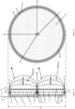
Figure 1a représente une section transversale selon l'axe (Ox) d'un repère orthogonal (O, x, y, z) d'un mode de réalisation du propulseur ionique selon l'invention, sur laquelle sont représentés de façon schématique les champs électrique et magnétique générés lors de l'utilisation dudit propulseur.ThereFigure 1a represents a cross section along the axis (Ox) of an orthogonal reference (O, x, y, z) of an embodiment of the ion thruster according to the invention, on which are schematically represented the electric and magnetic fields generated during the use of said propellant. -
La
Figure 1b représente une coupe selon l'axe AA' de laFigure 1a .ThereFigure 1b represents a section along the axis AA' of thePicture 1a . -
La
Figure 1c représente une vue de face du mode de réalisation de laFigure 1a .ThereFigure 1c shows a front view of the embodiment of thePicture 1a . -
Les
Figures 2 et3 représentent chacune la section transversale selon l'axe(Ox) de deux modes de réalisation distincts du propulseur ionique selon l'invention.THEFigure 2 And3 each represent the cross section along the axis (Ox) of two distinct embodiments of the ion thruster according to the invention.
La présente invention est décrite ci-dessous en référence aux
Selon un premier aspect, la présente invention porte sur un propulseur ionique 1 comprenant :
- un
corps 2 présentant une symétrie de révolution autour d'un axe de révolution (Ox) et ayant la forme générale d'un E capital selon une section transversale dans un plan passant par l'axe de révolution (Ox), lecorps 2 comprenant en son sein un circuit magnétique 3, unélément 4 générant un champ magnétique et un élément annulaire 5 générant un champ magnétique, leditélément 4 étant disposé selon la section transversale dans la traverse centrale du E capital, et ledit élément annulaire 5 présentant une symétrie de révolution autour de l'axe de révolution (Ox) et étant disposé selon la section transversale dans les traverses extrémales du E capital, l'élément 4 et l'élément annulaire 5 présentant une polarité magnétique opposée, - une
anode 9 recouvrant un espace annulaire interne 7, ledit espace annulaire présentant une symétrie de révolution autour de l'axe de révolution (Ox) et correspondant, selon la section transversale, au contrepoinçon du E capital, laditeanode 9 étant telle que, en fonctionnement, elle permet le passage du gaz de l'espace annulaire interne 7 vers la partie externe du bouclier selon une direction [Ox ), - une conduite de
gaz 6 traversant lecorps 2 et débouchant dans l'espace annulaire interne 7? - un
diffuseur 8 disposé dans ledit espace annulaire interne 7, et - une cathode (non représentée) reliée mécaniquement au
corps 2,
- a
body 2 having a symmetry of revolution around an axis of revolution (Ox) and having the general shape of a capital E according to a cross section in a plane passing through the axis of revolution (Ox), thebody 2 comprising within it amagnetic circuit 3, anelement 4 generating a magnetic field and anannular element 5 generating a magnetic field, saidelement 4 being arranged according to the cross section in the central crosspiece of the capital E, and saidannular element 5 having a symmetry of revolution around the axis of revolution (Ox) and being arranged according to the cross section in the end crosspieces of the capital E, theelement 4 and theannular element 5 having an opposite magnetic polarity, - an
anode 9 covering an internalannular space 7, said annular space having a symmetry of revolution around the axis of revolution (Ox) and corresponding, according to the cross section, to the counterpunch of the capital E, saidanode 9 being such that, in operation, it allows the passage of gas from the internalannular space 7 to the external part of the shield in a direction [Ox ), - a
gas line 6 passing through thebody 2 and opening into the internalannular space 7? - a
diffuser 8 disposed in said internalannular space 7, and - a cathode (not shown) mechanically connected to the
body 2,
Dans la présente invention, la coupe transversale passant par l'axe de révolution (Ox) est également appelée « coupe transversale ».In the present invention, the cross section passing through the axis of revolution (Ox) is also called “cross section”.
Au sens de la présente invention, le terme "contrepoinçon" désigne le ou les espaces intérieurs ouverts de certaines lettres.Within the meaning of the present invention, the term "counterpunch" designates the open interior space(s) of certain letters.
Au sens de la présente invention, tout élément qualifié "interne" est compris dans la partie interne du propulseur ionique 1, c'est-à-dire dans la zone comprise entre le plan (Oy, Oz) et le plan P de l'anode, c'est-à-dire le plan parallèle au plan (Oy, Oz) passant par P1, tandis que tout élément qualifié "externe" est compris en dehors de cette zone. L'espace annulaire interne 7 est donc compris dans la partie interne du propulseur ionique 1.Within the meaning of the present invention, any element qualified as "internal" is included in the internal part of the
Au sens de la présente invention, la direction [O
Selon un mode de réalisation, le corps 2 qui présente une symétrie de révolution autour de l'axe (Ox) peut notamment être de forme générale circulaire de rayon D/2. Il est formé d'une double enveloppe 2a, 2b dans laquelle est disposé le circuit magnétique 3. Selon une section transversale passant par l'axe (Ox), cette double enveloppe a la forme d'un E capital. L'enveloppe externe 2b est essentiellement plane, perpendiculaire à l'axe (Ox), son extrémité externe est pliée perpendiculairement selon la direction [O
Dans la double enveloppe constituant le corps 2 du propulseur, est disposé un circuit magnétique qui est un dispositif constitué d'un matériau capable de transporter un flux magnétique suffisant pour générer à l'extérieur un champ magnétique dont l'intensité est supérieure à 100 G, l'intensité étant mesurée suivant un axe parallèle à l'axe (Ox) et distant de D/4. Typiquement, le matériau capable de transporter un tel flux magnétique peut être choisi parmi le fer, les alliages fer-cobalt, et les ferrites. En fonction du matériau choisi le circuit magnétique 3 peut remplir partiellement ou entièrement le corps 2. Le circuit magnétique 3 relie les éléments 4 et 5. Il permet d'orienter le champ magnétique vers la partie externe du propulseur et il permet de donner la forme souhaité aux lignes du champ magnétique externe. En l'absence d'un tel circuit magnétique, la perte d'énergie magnétique utile serait très importante.In the double envelope constituting the
Selon l'invention l'anode 9 est un dispositif généralement plan constitué d'un matériau conducteur électrique et thermique. Elle est disposée en regard du corps 2 de telle sorte qu'elle recouvre l'espace annulaire interne 7. Selon les modes de réalisation décrits sur les
De façon avantageuse, l'anode 9 est perforée de façon à permettre ce passage du gaz. Selon un mode de réalisation, tel que représenté sur les
Selon un autre mode de réalisation, tel que représenté sur la
Selon l'invention, le diffuseur 8 est un dispositif comprenant un matériau poreux ou alvéolaire ou bien un dispositif mécanique à chicanes résistant à la chaleur. Le diffuseur 8, qui est disposé dans l'espace annulaire interne 7, permet d'homogénéiser le gaz introduit dans l'espace annulaire interne 7 par la conduite de gaz 6. Il est généralement non conducteur électrique.According to the invention, the
Cependant, selon un mode de réalisation particulier, le diffuseur peut être conducteur électrique et jouer alors le rôle d'anode. Ainsi, selon un mode de réalisation tel qu'illustré sur la
Le diffuseur 8 peut être constitué d'un matériau poreux ou alvéolaire choisi parmi les céramiques, telles que les mullites; les mousses métalliques dans le cas d'un diffuseur conducteur, et leur mélange.Diffuser 8 may consist of a porous or alveolar material chosen from ceramics, such as mullites; metal foams in the case of a conductive diffuser, and their mixture.
Afin d'homogénéiser le gaz introduit par la conduite de gaz 6 dans l'espace annulaire interne 7, le diffuseur 8 peut présenter une porosité (ou plus grande dimension passante des alvéoles) de 1 micron à 1 millimètre environ. La porosité ne doit pas être trop fine car elle doit permettre le passage du gaz mais elle ne doit pas être trop grossière de façon à ce que le gaz soit bien homogénéisé et que le plasma ne pénètre pas dans le diffuseur. La porosité du diffuseur peut être mesurée par porosimétrie Hg et par microscopie électronique.In order to homogenize the gas introduced through the
La conduite de gaz 6 est un dispositif permettant d'introduire un gaz depuis la partie externe du propulseur ionique 1 à travers le corps 2 dans l'espace annulaire interne 7. Typiquement, le propulseur ionique 1 selon l'invention peut comprendre1, 2 ou 3 conduites de gaz 6, plus particulièrement le propulseur ionique 1 selon l'invention peut comprendre 1 conduite de gaz 6.The
Au sens de la présente invention, on entend par "cathode" un dispositif constitué d'un matériau conducteur électrique qui émet des électrons.Within the meaning of the present invention, the term "cathode" means a device made of an electrically conductive material which emits electrons.
L'anode 9 et la cathode génèrent un champ électrique
L'élément 4 générant un champ magnétique, comme l'élément annulaire 5 générant un champ magnétique, est un dispositif destiné à produire un champ magnétique externe. Ils sont choisis indépendamment l'un de l'autre parmi un aimant permanent et une bobine magnétique. Chacun des éléments 4 et 5 peut être à la fois un aimant permanent et une bobine magnétique. De plus leur polarité magnétique est différente, i.e. que si l'élément 4 générant un champ magnétique présente un pôle nord alors l'élément annulaire 5 générant un champ magnétique présente un pôle sud, et vice-versa. The magnetic
Typiquement, l'élément 4 peut avoir une de forme générale cylindrique ou une forme générale annulaire comprenant un ou plusieurs éléments.Typically, the
Au sens de la présente invention, on entend par "aimant permanent" un dispositif constitué d'un alliage ferromagnétique comprenant un atome choisi parmi fer, cobalt, nickel, un atome du groupe des lanthanides, de préférence l'aimant permanent est un dispositif constitué d'un alliage ferromagnétique de formule Fe2O3XO, où X est un atome de manganèse, zinc, cobalt ou nickel. De préférence l'aimant permanent est un dispositif constitué de AINiCo, SmCo ou NdFeB et leur mélange.Within the meaning of the present invention, the term "permanent magnet" is understood to mean a device made up of a ferromagnetic alloy comprising an atom chosen from iron, cobalt, nickel, an atom from the lanthanide group, preferably the permanent magnet is a device made up of a ferromagnetic alloy of formula Fe 2 O 3 XO, where X is a manganese, zinc, cobalt or nickel atom. Preferably, the permanent magnet is a device consisting of AlNiCo, SmCo or NdFeB and their mixture.
L'élément 4 et l'élément annulaire 5 génèrent un champ magnétique à externe. Le champ magnétique
L'intensité maximale du champ magnétique
De façon avantageuse, la topologie et l'intensité du champ magnétique
Dans le propulseur ionique 1 selon l'invention, le diffuseur 8 et l'anode 9 occupent au moins 50%, de préférence de 60 à 100%, et préférentiellement de 75% à 95% de l'espace annulaire interne 7.In the
Sans vouloir être liés par aucune théorie, les inventeurs sont d'avis que l'occupation de l'espace annulaire interne 7 par le diffuseur 8 et l'anode 9 telle que définie ci-dessus permet de créer la décharge plasma et de la confiner dans la partie externe du propulseur ionique 1, en particulier de la confiner dans l'espace de confinement externe.Without wishing to be bound by any theory, the inventors are of the opinion that the occupation of the internal
De plus grâce à cette occupation de l'espace annulaire interne 7 par le diffuseur 8 et l'anode 9 telle que définie ci-dessus, le corps 2 du propulseur ionique 1 selon l'invention présente une taille de 2,5 à 5 fois inférieure à la taille du corps d'un propulseur ionique classique. En effet le corps 2 présente un diamètre D 5 à 10 fois supérieur à l'épaisseur ε, le diamètre D étant la plus grande dimension du corps 2 et l'épaisseur ε étant la distance entre les points O (qui est le point d'intersection entre l'enveloppe externe 2b et l'axe de révolution (Ox)) et P1 (qui est le point d'intersection du plan P et de l'axe de révolution (Ox)). En comparaison, le corps d'un propulseur ionique classique présente un diamètre de 2 à 4 fois sa hauteur. Le propulseur ionique 1 selon l'invention est donc avantageusement plus mince qu'un propulseur ionique classique. Le propulseur ionique 1 selon l'invention est par conséquent plus léger qu'un propulseur ionique classique.Moreover, thanks to this occupation of the internal
De façon avantageuse, le corps 2 de forme générale cylindrique, en particulier circulaire favorise la génération du champ magnétique
Selon un mode de réalisation, le corps 2 peut être constitué d'un matériau choisi parmi les céramiques, telles que alumine, zircone, carbure ; des métaux tels que tantale, aluminium, des polymères tels que PEEK (polyétheréthercétone), polymères thermodurs ; le carbone et leur mélange.According to one embodiment, the
Selon un mode de réalisation particulier, l'enveloppe 2a et l'enveloppe 2b constitutives du corps peuvent être constituées de matériaux différents.According to a particular embodiment, the
Selon un mode de réalisation, l'anode 9 peut être constituée d'un matériau choisi parmi des métaux tels que aluminium, tantale, aciers, ou carbone et leur mélange.According to one embodiment, the
L'interaction directe du propulseur ionique selon l'invention avec la décharge plasma étant réduite, les matériaux du corps notamment 2b, du diffuseur 8 et de l'anode 9 n'ont pas à résister aux contraintes générées par la décharge plasma créée et confinée dans la partie externe du propulseur ionique 1 selon l'invention. De façon avantageuse, ces matériaux sont moins onéreux, plus légers et plus faciles à détruire lors de la rentrée dans l'atmosphère que ceux mis en oeuvre dans un propulseur ionique classique. Le propulseur ionique 1 selon l'invention est donc plus économique qu'un propulseur ionique classique et crée peu ou pas de débris spatiaux.The direct interaction of the ion thruster according to the invention with the plasma discharge being reduced, the materials of the body in particular 2b, of the
Typiquement, l'anode 9 peut avoir différentes configurations. Par exemple l'anode 9 peut être un disque de sorte qu'elle n'est pas en contact avec les traverses extrémales du E capital. L'anode 9 peut également être un anneau présentant une symétrie ou une asymétrie de révolution autour de l'axe de révolution (Ox) et comprenant un orifice annulaire présentant une symétrie ou une asymétrie de révolution autour de l'axe de révolution (Ox), ledit orifice étant disposé de sorte que l'anode 9 soit au moins en contact avec la traverse centrale du E capital. L'anode 9 peut aussi être un anneau multiple présentant une symétrie ou une asymétrie de révolution autour de l'axe de révolution (Ox) et comprenant au moins deux orifices annulaires présentant une symétrie ou une asymétrie de révolution autour de l'axe de révolution (Ox), lesdits orifices annulaires étant disposés de sorte que l'anode 9 soit au moins en contact avec la traverse centrale du E capital. L'anode 9 peut également être une grille.Typically, the
Quelle que soit la configuration de l'anode 9, il est préférable que, au voisinage d'un axe parallèle à (Ox) et distant de D/4, la surface de l'anode 9 soit parallèle aux lignes du champ magnétique
En plus de l'interaction magnétique, l'anode 9 subit, de la part de la décharge plasma, une contrainte thermique. Cette contrainte thermique est réduite par le confinement externe de ladite décharge plasma.In addition to the magnetic interaction, the
Selon un mode de réalisation particulier, l'anode 9 peut être en contact avec le diffuseur 8.According to a particular embodiment, the
Selon un autre mode de réalisation particulier, l'anode 9 et le diffuseur 8 peuvent être le même élément. De façon avantageuse, utiliser un seul élément au lieu de deux permet de réduire la taille et la masse du propulseur ionique 1.According to another particular embodiment, the
Typiquement la cathode est comprise dans la partie externe du propulseur.Typically the cathode is included in the external part of the thruster.
Selon un mode de réalisation particulier, la cathode peut être comprise dans la partie interne du propulseur ionique 1 selon l'invention.According to a particular embodiment, the cathode can be included in the internal part of the
Selon ce mode de réalisation, la cathode peut être disposée, selon la section transversale, dans la traverse centrale du E capital, de préférence dans l'élément 4 ayant une forme générale annulaire. La cathode peut également être annulaire et être disposée selon la section transversale S dans les traverses extrémales E du corps 2. De façon avantageuse, la taille du propulseur ionique 1 selon ce mode de réalisation est réduite.According to this embodiment, the cathode can be arranged, according to the cross section, in the central crosspiece of the capital E, preferably in the
Selon ce mode de réalisation, la cathode doit être constituée d'un matériau émetteur d'électrons fonctionnant à relativement basse température afin de ne pas endommager l'élément 4 et l'élément annulaire 5 générant un champ magnétique. Typiquement ce matériau un aluminate de calcium tel que le dodécacalcium hepta-aluminate C12A7 .According to this embodiment, the cathode must be made of an electron-emitting material operating at relatively low temperature so as not to damage the
Selon un mode de réalisation, le propulseur ionique 1 comprend en outre une protection des pôles magnétiques 10 et une protection annulaire des pôles magnétiques 11. La protection 10 recouvre l'empattement de la traverse centrale du E capital. La protection annulaire 11 recouvre l'empattement des traverses extrémales du E capital. De façon avantageuse, ces deux protections permettent de protéger la seconde extrémité du corps 2 contre le champ magnétique
Typiquement, la protection 10 et la protection annulaire 11 sont constituées d'un matériau choisi parmi les céramiques, telles que alumine; les métaux, tels que aluminium ou tantale ; carbone et leur mélange, de préférence alumine, carbone et leur, mélange.Typically,
Le propulseur ionique 1 selon l'invention peut en outre comprendre des drains thermiques pour dissiper la charge thermique générée par la décharge plasma et maintenir le propulseur ionique 1 à une température relativement basse, i.e. de 100 à 200°C, telle que mesurée au niveau des aimants . En effet, maintenir le propulseur ionique 1 dans cette gamme de température permet de ne pas endommager les éléments du propulseur ionique 1 tels que l'anode 9, l'élément 4 et l'élément annulaire 5 générant un champ magnétique, et donc augmente la durée de vie du propulseur ionique 1. Typiquement les drains peuvent être reliés à des radiateurs qui dissipent la chaleur par radiation pour faciliter le maintien du propulseur ionique 1 dans cette gamme de température.The
Compte tenu de ses propriétés, en particulier de sa faible taille, de sa faible masse, de la possibilité de générer une décharge plasma dans la partie externe du propulseur ionique 1 selon l'invention et de la confiner dans l'espace de confinement externe, par exemple dans le vide de l'espace, le propulseur ionique 1 selon l'invention peut être utilisé pour la propulsion d'un véhicule spatial tel qu'une sonde, un satellite, une capsule spatiale, une navette spatiale ou une station spatiale.Given its properties, in particular its small size, its low mass, the possibility of generating a plasma discharge in the external part of the
Typiquement le propulseur ionique 1 selon l'invention est adapté à tout type de satellite, notamment des satellites de faible masse tels que les mini-satellites, les micro-satellites, les nano-satellites et les cubsats, en particulier les mini-satellites et les micro-satellites mais aussi à des satellites de grandes tailles.Typically, the
De façon avantageuse, générer et confiner la décharge plasma dans cet espace de confinement externe permet de réduire l'interaction directe des éléments du propulseur ionique selon l'invention avec la décharge plasma. Par rapport à un propulseur ionique classique, la durée de vie du propulseur ionique selon l'invention est donc augmentée. De plus en réduisant l'interaction directe des éléments du propulseur ionique selon l'invention avec la décharge plasma, les pertes aux parois des éléments sont réduites significativement, le propulseur ionique selon l'invention présente donc un bon rendement et une consommation inférieure à celle d'un propulseur ionique classique. Le propulseur ionique selon l'invention n'ayant pas à subir toutes les contraintes générées par la décharge plasma, des éléments dont les matériaux sont moins onéreux, plus légers et plus faciles à détruire lors de la rentrée dans l'atmosphère que ceux mis en oeuvre dans un propulseur ionique classique peuvent être utilisés. Pour la même raison, le propulseur ionique selon l'invention peut fonctionner à des tensions plus hautes qu'un propulseur ionique classique et donc fonctionner à haute impulsion spécifique, ce qui réduit sa consommation. Le propulseur ionique selon l'invention peut aussi mettre en oeuvre des carburants alternatifs moins onéreux que le xénon mis en oeuvre dans un propulseur ionique classique. Le propulseur ionique selon l'invention a donc avantageusement une durée de vie supérieure à un propulseur ionique classique tout en étant plus petit, plus léger, plus économique et en créant peu ou pas de débris spatiaux conformément aux réglementations en la matière.Advantageously, generating and confining the plasma discharge in this external confinement space makes it possible to reduce the direct interaction of the elements of the ion thruster according to the invention with the plasma discharge. Compared to a conventional ion thruster, the lifetime of the ion thruster according to the invention is therefore increased. Moreover, by reducing the direct interaction of the elements of the ion thruster according to the invention with the plasma discharge, the losses at the walls of the elements are significantly reduced, the ion thruster according to the invention therefore has good efficiency and lower consumption than that of a conventional ion thruster. The ion thruster according to the invention not having to undergo all the stresses generated by the plasma discharge, elements whose materials are less expensive, lighter and easier to destroy during re-entry into the atmosphere than those put into working in a conventional ion thruster can be used. For the same reason, the ion thruster according to the invention can operate at higher voltages than a conventional ion thruster and therefore operate at high specific impulse, which reduces its consumption. The ion thruster according to the invention can also use alternative fuels that are less expensive than the xenon used in a conventional ion thruster. The ion thruster according to the invention therefore advantageously has a longer lifetime than a conventional ion thruster while being smaller, lighter, more economical and creating little or no space debris in accordance with the regulations in the matter.
Par rapport à des propulseurs ioniques classiques, le propulseur ionique selon l'invention, du fait que la décharge plasma est externe, est plus facilement extrapolable au grandes tailles nécessitant une forte poussée, et est particulièrement approprié pour être extrapolé aux petites tailles car l'effet de paroi est moins limitant que dans les propulseurs classiques.Compared to conventional ion thrusters, the ion thruster according to the invention, because the plasma discharge is external, is more easily extrapolated to large sizes requiring a strong thrust, and is particularly suitable to be extrapolated to small sizes because the wall effect is less limiting than in conventional thrusters.
Selon un autre aspect, l'invention porte sur un procédé de génération d'une poussée propulsive d'un véhicule spatial au moyen du propulseur ionique 1 selon l'invention comprenant les étapes suivantes:
- a) introduction d'un gaz par la conduite de
gaz 6 dans l'espace annulaireinterne 7 du propulseur ionique 1, - b) génération du champ électrique
E externe par l'anode 9 et une cathode et génération d'un champ magnétiqueB externe par l'élément 4 et l'élément annulaire 5 générant un champ magnétique créant ainsi un espace de confinement externe au propulseur ionique 1, l'espace de confinement externe et l'espace annulaire interne étant positionnés de part et d'autre de l'anode 9, - c) ionisation du gaz introduit dans l'espace annulaire
interne 7 par le champ électriqueE externe, et génération d'une décharge plasma à partir du gaz ionisé dans l'espace de confinement externe, - d) confinement de la décharge plasma dans l'espace de confinement externe
- e) accélération des ions de la décharge plasma par le champ électrique et éjection des ions hors de l'espace de confinement, et
- f) apport par la cathode des électrons nécessaires pour assurer le maintien de la décharge plasma et la neutralité électrique.
- a) introduction of a gas through the
gas line 6 into the internalannular space 7 of theion thruster 1, - b) generation of the electric field
E external via theanode 9 and a cathode and generation of a magnetic fieldB external by theelement 4 and theannular element 5 generating a magnetic field thus creating an external confinement space to theion thruster 1, the external confinement space and the internal annular space being positioned on either side of theanode 9, - c) ionization of the gas introduced into the internal
annular space 7 by the electric fieldE external, and generation of a plasma discharge from the ionized gas in the external confinement space, - d) confinement of the plasma discharge in the outer confinement space
- e) acceleration of the ions from the plasma discharge by the electric field and ejection of the ions out of the confinement space, and
- f) contribution by the cathode of the electrons necessary to ensure the maintenance of the plasma discharge and electrical neutrality.
Dans le procédé ci-dessus, les étapes a) à e) peuvent être réalisées simultanément ou séquentiellement.In the above process, steps a) to e) can be carried out simultaneously or sequentially.
Le procédé est particulièrement adapté pour un véhicule spatial tel qu'une sonde, un satellite, une capsule spatiale, une navette spatiale ou une station spatiale. Le procédé selon l'invention est tout particulièrement adapté à des satellites de faible masse tels que les mini-satellites, les micro-satellites, les nano-satellites et les cubsats, en particulier les mini-satellites et les micro-satellites.The method is particularly suitable for a space vehicle such as a probe, a satellite, a space capsule, a space shuttle or a space station. The method according to the invention is very particularly suitable for low-mass satellites such as mini-satellites, micro-satellites, nano-satellites and cubsats, in particular mini-satellites and micro-satellites.
Au cours de l'étape a) un gaz est introduit dans l'espace annulaire interne 7 par la conduite de gaz 6. Typiquement ce gaz est un gaz rare tel que le krypton, l'argon, le xénon ou leur mélange. De façon avantageuse, utiliser le krypton ou l'argon accroit significativement le gain financier du procédé de l'invention.During step a) a gas is introduced into the internal
Typiquement le gaz peut être introduit au voisinage du diffuseur 8 ou directement dans le diffuseur 8.Typically the gas can be introduced near the
Dans le procédé selon l'invention, l'interaction entre le propulseur ionique et la décharge plasma est réduite car la décharge plasma est générée et confinée dans l'espace de confinement externe. Le champ électrique
De façon avantageuse, une tension de fonctionnement dans les gammes ci-dessus permet un fonctionnement à haute impulsion spécifique ce qui a pour effet de réduire la consommation en gaz du propulseur ionique 1.Advantageously, an operating voltage in the above ranges allows operation at high specific impulse, which has the effect of reducing the gas consumption of the
Au cours de l'étape d), la décharge plasma est confinée dans l'espace de confinement externe formant ainsi une décharge plasma confinée. Lors de l'étape e) les ions de cette décharge plasma confinée sont accélérés par le champ électrique et éjectés hors de l'espace de confinement.During step d), the plasma discharge is confined in the outer confinement space thus forming a confined plasma discharge. During step e) the ions of this confined plasma discharge are accelerated by the electric field and ejected out of the confinement space.
Claims (10)
- An ion thruster (1) comprising:- a body (2) having a symmetry of revolution about an axis of revolution (Ox) and having the shape of a capital E in a cross section passing through the axis of revolution (Ox), the body (2) comprising therein a magnetic circuit (3), an element (4) that generates a magnetic field and an annular element (5) that generates a magnetic field, said element that generates a magnetic field (4) being placed in the cross section in the central arm of the capital E, and said annular element (5) having a symmetry of revolution about the axis of revolution (Ox) and being placed in the cross section S in the upper and lower arms of the capital E, the element (4) that generates a magnetic field and the annular element (5) that generates a magnetic field having opposite magnetic polarities,- an anode (9) arranged opposite the body and covering an internal annular space (7), said internal annular space having a symmetry of revolution about the axis of revolution (Ox) and corresponding, in the cross section, to the counter of the capital E, said anode being such that, in operation, it allows the passage of the gas from the internal annular space (7) to the external portion in the direction of the axis of revolution,- a gas line (6) passing through the body (2) and opening into the internal annular space (7),- a diffuser (8) placed in said internal annular space (7), and- a cathode that is mechanically joined to the body (2),said diffuser (8) and said anode (9) occupying at least 50%, preferably from 60 to 100% and preferentially from 75% to 95% of the internal annular space (7).
- The ion thruster (1) according to claim 1, wherein the anode (9) contacts the diffuser.
- The ion thruster (1) according to claim 1 or claim 2, wherein the diffuser is a porous or cellular diffuser or a chicaned mechanical diffuser (8).
- The ion thruster (1) according to any one of claims 1 to 3, wherein the anode (9) has at least one orifice opening into the annular space (7).
- The ion thruster according to any one of claims 1 to 4, characterised in that the anode is made of a material chosen from metals such as aluminium, tantalum, steels or carbon and mixtures thereof.
- The ion thruster (1) comprising:- a body (2) having a symmetry of revolution about an axis of revolution (Ox) and having the shape of a capital E in a cross section passing through the axis of revolution (Ox), the body (2) comprising therein a magnetic circuit (3), an element (4) that generates a magnetic field and an annular element (5) that generates a magnetic field, said element that generates a magnetic field (4) being placed in the cross section in the central arm of the capital E, and said annular element (5) having a symmetry of revolution about the axis of revolution (Ox) and being placed in the cross section S in the upper and lower arms of the capital E, the element (4) that generates a magnetic field and the annular element (5) that generates a magnetic field having opposite magnetic polarities,- an anode-diffuser assembly arranged opposite the body and arranged inside and covering an internal annular space (7), said internal annular space having a symmetry of revolution about the axis of revolution (Ox) and corresponding, in the cross section, to the counter of the capital E, said anode-diffuser assembly being such that, in operation, it allows the passage of the gas from the internal annular space (7) to the external portion in the direction of the axis of revolution,- a gas line (6) passing through the body (2) and opening into the internal annular space (7),- a cathode that is mechanically joined to the body (2),said anode-diffuser assembly occupying at least 50%, preferably from 60 to 100% and preferentially from 75% to 95% of the internal annular space (7).
- The ion thruster (1) according to any one of claims 1 to 6, wherein the cathode is:- placed in the central arm of the capital E, or- is annular and is placed in the cross section S in the upper and lower arms E of the body (2).
- The ion thruster (1) according to any one of claims 1 to 7, wherein a protection of the magnetic poles (10) covers the serif of the central arm of the capital E and an annular protection of the magnetic poles (11) covers the serif of the upper and lower arms of the capital E.
- The use of an ion thruster (1) such as defined in claims 1 to 8 to propel a space vehicle such as a probe, a satellite, a space capsule, a space shuttle or a space station.
- A method for generating propulsive thrust for a space vehicle by means of an ion thruster (1) such as defined in claims 1 to 8 comprising the following steps:a) introducing a gas via the gas line (6) into the internal annular space (7) of the ion thruster (1),b) generating an external electric field
E via the anode (9) and the cathode and generating an external magnetic fieldB via the element (4) that generates, a magnetic field and the annular element (5) that generates a magnetic field, thus creating a confinement space external to the ion thruster (1), the external confinement space and the internal annular space being positioned on either side of the anode (9),c) ionising the gas introduced into the internal annular space (7) with the external electric fieldE , and generating a plasma discharge from the ionised gas in the external confinement space,d) confining the plasma discharge in the external confinement space,e) accelerating the ions of the plasma discharge with the electric field and ejecting the ions out of the confining space.f) supplying, via the cathode, the electrons required to ensure the plasma discharge and electrical neutrality are maintained.
Applications Claiming Priority (2)
| Application Number | Priority Date | Filing Date | Title |
|---|---|---|---|
| FR1659808A FR3057307B1 (en) | 2016-10-11 | 2016-10-11 | IONIC PROPELLER WITH EXTERNAL PLASMA DISCHARGE |
| PCT/FR2017/052789 WO2018069642A1 (en) | 2016-10-11 | 2017-10-11 | Ion thruster with external plasma discharge |
Publications (2)
| Publication Number | Publication Date |
|---|---|
| EP3526472A1 EP3526472A1 (en) | 2019-08-21 |
| EP3526472B1 true EP3526472B1 (en) | 2023-08-16 |
Family
ID=58314334
Family Applications (1)
| Application Number | Title | Priority Date | Filing Date |
|---|---|---|---|
| EP17793998.0A Active EP3526472B1 (en) | 2016-10-11 | 2017-10-11 | Ion thruster with external plasma discharge |
Country Status (4)
| Country | Link |
|---|---|
| US (1) | US10961989B2 (en) |
| EP (1) | EP3526472B1 (en) |
| FR (1) | FR3057307B1 (en) |
| WO (1) | WO2018069642A1 (en) |
Families Citing this family (3)
| Publication number | Priority date | Publication date | Assignee | Title |
|---|---|---|---|---|
| CN110748467B (en) * | 2019-10-29 | 2020-08-21 | 中国人民解放军国防科技大学 | Intelligent control air suction type electric propulsion system applicable to multiple flow states |
| US12049878B2 (en) * | 2021-08-26 | 2024-07-30 | The Trustees Of Princeton University | Segmented wall-less hall thruster |
| CN114658625B (en) * | 2022-03-24 | 2022-09-09 | 哈尔滨工业大学 | High-excitation-performance rear-loading magnetic field Hall thruster magnetic circuit structure and design method |
Family Cites Families (5)
| Publication number | Priority date | Publication date | Assignee | Title |
|---|---|---|---|---|
| US5646476A (en) * | 1994-12-30 | 1997-07-08 | Electric Propulsion Laboratory, Inc. | Channel ion source |
| US6982520B1 (en) * | 2001-09-10 | 2006-01-03 | Aerojet-General Corporation | Hall effect thruster with anode having magnetic field barrier |
| WO2011017314A2 (en) * | 2009-08-03 | 2011-02-10 | General Plasma, Inc. | Closed drift ion source with symmetric magnetic field |
| US20150128560A1 (en) * | 2013-10-04 | 2015-05-14 | The Regents Of The University Of California | Magnetically shielded miniature hall thruster |
| JP6318447B2 (en) * | 2014-05-23 | 2018-05-09 | 三菱重工業株式会社 | Plasma acceleration apparatus and plasma acceleration method |
-
2016
- 2016-10-11 FR FR1659808A patent/FR3057307B1/en active Active
-
2017
- 2017-10-11 US US16/341,021 patent/US10961989B2/en active Active
- 2017-10-11 WO PCT/FR2017/052789 patent/WO2018069642A1/en unknown
- 2017-10-11 EP EP17793998.0A patent/EP3526472B1/en active Active
Also Published As
| Publication number | Publication date |
|---|---|
| FR3057307B1 (en) | 2018-11-02 |
| EP3526472A1 (en) | 2019-08-21 |
| US20200040877A1 (en) | 2020-02-06 |
| WO2018069642A1 (en) | 2018-04-19 |
| US10961989B2 (en) | 2021-03-30 |
| FR3057307A1 (en) | 2018-04-13 |
Similar Documents
| Publication | Publication Date | Title |
|---|---|---|
| EP0662195B1 (en) | Reduced length plasma engine with closed electron deviation | |
| EP3526472B1 (en) | Ion thruster with external plasma discharge | |
| EP0650557B1 (en) | Fixed plasma motor | |
| EP1496727B1 (en) | Closed electron drift plasma accelerator | |
| EP2433002B1 (en) | Hall effect plasma thruster | |
| EP0711100B1 (en) | Plasma production device, allowing a dissociation between microwave propagation and absorption zones | |
| WO1998053201A1 (en) | Device for concentrating ion beams for hydromagnetic propulsion means and hydromagnetic propulsion means equipped with same | |
| WO2009112667A1 (en) | Filament electrical discharge ion source | |
| WO2004007957A2 (en) | Hall-effect plasma thruster | |
| EP2079096B1 (en) | Ion source with filament electric discharge | |
| EP3250822B1 (en) | Hall effect thruster, and spacecraft including such a thruster | |
| EP4153862A1 (en) | Magnetic circuit for creating a magnetic field in a main annular ionisation and acceleration channel of a hall-effect plasma thruster | |
| FR2757310A1 (en) | MAGNETIC SYSTEM, IN PARTICULAR FOR ECR SOURCES, ALLOWING THE CREATION OF CLOSED SURFACES OF EQUIMODULE B OF ANY SHAPE AND DIMENSIONS | |
| EP0813223B1 (en) | Magnetic field generation means and ECR ion source using the same | |
| EP1568091B1 (en) | Fuel cell comprising a magnetic cathode with static pumping | |
| FR2668642A1 (en) | SOURCE OF HIGHLY LOADED IONS WITH POLARIZABLE PROBE AND ELECTRONIC CYCLOTRONIC RESONANCE. | |
| EP0374011B1 (en) | Process and device using an ECR source for the production of strongly charged heavy ions | |
| EP3232056B1 (en) | Discharge chamber for an ion drive and ion drive having a discharge chamber | |
| FR2820880A1 (en) | Semiconductor material etching ion source multiple charged beam having ionization reactor with extractor wall/ionization input and input/output poles with enclosing flux magnetic field. | |
| EP1272015A1 (en) | Cyclotron resonance device for the generation of ions with variable positive charge | |
| CA2139581A1 (en) | Fixed plasma motor |
Legal Events
| Date | Code | Title | Description |
|---|---|---|---|
| STAA | Information on the status of an ep patent application or granted ep patent |
Free format text: STATUS: UNKNOWN |
|
| STAA | Information on the status of an ep patent application or granted ep patent |
Free format text: STATUS: THE INTERNATIONAL PUBLICATION HAS BEEN MADE |
|
| PUAI | Public reference made under article 153(3) epc to a published international application that has entered the european phase |
Free format text: ORIGINAL CODE: 0009012 |
|
| STAA | Information on the status of an ep patent application or granted ep patent |
Free format text: STATUS: REQUEST FOR EXAMINATION WAS MADE |
|
| 17P | Request for examination filed |
Effective date: 20190416 |
|
| AK | Designated contracting states |
Kind code of ref document: A1 Designated state(s): AL AT BE BG CH CY CZ DE DK EE ES FI FR GB GR HR HU IE IS IT LI LT LU LV MC MK MT NL NO PL PT RO RS SE SI SK SM TR |
|
| AX | Request for extension of the european patent |
Extension state: BA ME |
|
| DAV | Request for validation of the european patent (deleted) | ||
| DAX | Request for extension of the european patent (deleted) | ||
| STAA | Information on the status of an ep patent application or granted ep patent |
Free format text: STATUS: EXAMINATION IS IN PROGRESS |
|
| 17Q | First examination report despatched |
Effective date: 20220202 |
|
| GRAP | Despatch of communication of intention to grant a patent |
Free format text: ORIGINAL CODE: EPIDOSNIGR1 |
|
| STAA | Information on the status of an ep patent application or granted ep patent |
Free format text: STATUS: GRANT OF PATENT IS INTENDED |
|
| INTG | Intention to grant announced |
Effective date: 20230314 |
|
| GRAS | Grant fee paid |
Free format text: ORIGINAL CODE: EPIDOSNIGR3 |
|
| GRAA | (expected) grant |
Free format text: ORIGINAL CODE: 0009210 |
|
| STAA | Information on the status of an ep patent application or granted ep patent |
Free format text: STATUS: THE PATENT HAS BEEN GRANTED |
|
| AK | Designated contracting states |
Kind code of ref document: B1 Designated state(s): AL AT BE BG CH CY CZ DE DK EE ES FI FR GB GR HR HU IE IS IT LI LT LU LV MC MK MT NL NO PL PT RO RS SE SI SK SM TR |
|
| REG | Reference to a national code |
Ref country code: GB Ref legal event code: FG4D Free format text: NOT ENGLISH |
|
| REG | Reference to a national code |
Ref country code: CH Ref legal event code: EP |
|
| REG | Reference to a national code |
Ref country code: DE Ref legal event code: R096 Ref document number: 602017072835 Country of ref document: DE |
|
| REG | Reference to a national code |
Ref country code: IE Ref legal event code: FG4D Free format text: LANGUAGE OF EP DOCUMENT: FRENCH |
|
| REG | Reference to a national code |
Ref country code: LT Ref legal event code: MG9D |
|
| REG | Reference to a national code |
Ref country code: NL Ref legal event code: MP Effective date: 20230816 |
|
| REG | Reference to a national code |
Ref country code: AT Ref legal event code: MK05 Ref document number: 1600291 Country of ref document: AT Kind code of ref document: T Effective date: 20230816 |
|
| PG25 | Lapsed in a contracting state [announced via postgrant information from national office to epo] |
Ref country code: GR Free format text: LAPSE BECAUSE OF FAILURE TO SUBMIT A TRANSLATION OF THE DESCRIPTION OR TO PAY THE FEE WITHIN THE PRESCRIBED TIME-LIMIT Effective date: 20231117 |
|
| PGFP | Annual fee paid to national office [announced via postgrant information from national office to epo] |
Ref country code: GB Payment date: 20231019 Year of fee payment: 7 |
|
| PG25 | Lapsed in a contracting state [announced via postgrant information from national office to epo] |
Ref country code: IS Free format text: LAPSE BECAUSE OF FAILURE TO SUBMIT A TRANSLATION OF THE DESCRIPTION OR TO PAY THE FEE WITHIN THE PRESCRIBED TIME-LIMIT Effective date: 20231216 |
|
| PG25 | Lapsed in a contracting state [announced via postgrant information from national office to epo] |
Ref country code: SE Free format text: LAPSE BECAUSE OF FAILURE TO SUBMIT A TRANSLATION OF THE DESCRIPTION OR TO PAY THE FEE WITHIN THE PRESCRIBED TIME-LIMIT Effective date: 20230816 Ref country code: RS Free format text: LAPSE BECAUSE OF FAILURE TO SUBMIT A TRANSLATION OF THE DESCRIPTION OR TO PAY THE FEE WITHIN THE PRESCRIBED TIME-LIMIT Effective date: 20230816 Ref country code: PT Free format text: LAPSE BECAUSE OF FAILURE TO SUBMIT A TRANSLATION OF THE DESCRIPTION OR TO PAY THE FEE WITHIN THE PRESCRIBED TIME-LIMIT Effective date: 20231218 Ref country code: NO Free format text: LAPSE BECAUSE OF FAILURE TO SUBMIT A TRANSLATION OF THE DESCRIPTION OR TO PAY THE FEE WITHIN THE PRESCRIBED TIME-LIMIT Effective date: 20231116 Ref country code: NL Free format text: LAPSE BECAUSE OF FAILURE TO SUBMIT A TRANSLATION OF THE DESCRIPTION OR TO PAY THE FEE WITHIN THE PRESCRIBED TIME-LIMIT Effective date: 20230816 Ref country code: LV Free format text: LAPSE BECAUSE OF FAILURE TO SUBMIT A TRANSLATION OF THE DESCRIPTION OR TO PAY THE FEE WITHIN THE PRESCRIBED TIME-LIMIT Effective date: 20230816 Ref country code: LT Free format text: LAPSE BECAUSE OF FAILURE TO SUBMIT A TRANSLATION OF THE DESCRIPTION OR TO PAY THE FEE WITHIN THE PRESCRIBED TIME-LIMIT Effective date: 20230816 Ref country code: IS Free format text: LAPSE BECAUSE OF FAILURE TO SUBMIT A TRANSLATION OF THE DESCRIPTION OR TO PAY THE FEE WITHIN THE PRESCRIBED TIME-LIMIT Effective date: 20231216 Ref country code: HR Free format text: LAPSE BECAUSE OF FAILURE TO SUBMIT A TRANSLATION OF THE DESCRIPTION OR TO PAY THE FEE WITHIN THE PRESCRIBED TIME-LIMIT Effective date: 20230816 Ref country code: GR Free format text: LAPSE BECAUSE OF FAILURE TO SUBMIT A TRANSLATION OF THE DESCRIPTION OR TO PAY THE FEE WITHIN THE PRESCRIBED TIME-LIMIT Effective date: 20231117 Ref country code: FI Free format text: LAPSE BECAUSE OF FAILURE TO SUBMIT A TRANSLATION OF THE DESCRIPTION OR TO PAY THE FEE WITHIN THE PRESCRIBED TIME-LIMIT Effective date: 20230816 Ref country code: AT Free format text: LAPSE BECAUSE OF FAILURE TO SUBMIT A TRANSLATION OF THE DESCRIPTION OR TO PAY THE FEE WITHIN THE PRESCRIBED TIME-LIMIT Effective date: 20230816 |
|
| PGFP | Annual fee paid to national office [announced via postgrant information from national office to epo] |
Ref country code: FR Payment date: 20231023 Year of fee payment: 7 Ref country code: DE Payment date: 20231011 Year of fee payment: 7 |
|
| PG25 | Lapsed in a contracting state [announced via postgrant information from national office to epo] |
Ref country code: PL Free format text: LAPSE BECAUSE OF FAILURE TO SUBMIT A TRANSLATION OF THE DESCRIPTION OR TO PAY THE FEE WITHIN THE PRESCRIBED TIME-LIMIT Effective date: 20230816 |
|
| PG25 | Lapsed in a contracting state [announced via postgrant information from national office to epo] |
Ref country code: ES Free format text: LAPSE BECAUSE OF FAILURE TO SUBMIT A TRANSLATION OF THE DESCRIPTION OR TO PAY THE FEE WITHIN THE PRESCRIBED TIME-LIMIT Effective date: 20230816 |
|
| PG25 | Lapsed in a contracting state [announced via postgrant information from national office to epo] |
Ref country code: SM Free format text: LAPSE BECAUSE OF FAILURE TO SUBMIT A TRANSLATION OF THE DESCRIPTION OR TO PAY THE FEE WITHIN THE PRESCRIBED TIME-LIMIT Effective date: 20230816 Ref country code: RO Free format text: LAPSE BECAUSE OF FAILURE TO SUBMIT A TRANSLATION OF THE DESCRIPTION OR TO PAY THE FEE WITHIN THE PRESCRIBED TIME-LIMIT Effective date: 20230816 Ref country code: ES Free format text: LAPSE BECAUSE OF FAILURE TO SUBMIT A TRANSLATION OF THE DESCRIPTION OR TO PAY THE FEE WITHIN THE PRESCRIBED TIME-LIMIT Effective date: 20230816 Ref country code: EE Free format text: LAPSE BECAUSE OF FAILURE TO SUBMIT A TRANSLATION OF THE DESCRIPTION OR TO PAY THE FEE WITHIN THE PRESCRIBED TIME-LIMIT Effective date: 20230816 Ref country code: DK Free format text: LAPSE BECAUSE OF FAILURE TO SUBMIT A TRANSLATION OF THE DESCRIPTION OR TO PAY THE FEE WITHIN THE PRESCRIBED TIME-LIMIT Effective date: 20230816 Ref country code: CZ Free format text: LAPSE BECAUSE OF FAILURE TO SUBMIT A TRANSLATION OF THE DESCRIPTION OR TO PAY THE FEE WITHIN THE PRESCRIBED TIME-LIMIT Effective date: 20230816 Ref country code: SK Free format text: LAPSE BECAUSE OF FAILURE TO SUBMIT A TRANSLATION OF THE DESCRIPTION OR TO PAY THE FEE WITHIN THE PRESCRIBED TIME-LIMIT Effective date: 20230816 |
|
| REG | Reference to a national code |
Ref country code: DE Ref legal event code: R097 Ref document number: 602017072835 Country of ref document: DE |
|
| PG25 | Lapsed in a contracting state [announced via postgrant information from national office to epo] |
Ref country code: MC Free format text: LAPSE BECAUSE OF FAILURE TO SUBMIT A TRANSLATION OF THE DESCRIPTION OR TO PAY THE FEE WITHIN THE PRESCRIBED TIME-LIMIT Effective date: 20230816 |
|
| REG | Reference to a national code |
Ref country code: CH Ref legal event code: PL |
|
| REG | Reference to a national code |
Ref country code: BE Ref legal event code: MM Effective date: 20231031 |
|
| PG25 | Lapsed in a contracting state [announced via postgrant information from national office to epo] |
Ref country code: LU Free format text: LAPSE BECAUSE OF NON-PAYMENT OF DUE FEES Effective date: 20231011 |
|
| PLBE | No opposition filed within time limit |
Free format text: ORIGINAL CODE: 0009261 |
|
| STAA | Information on the status of an ep patent application or granted ep patent |
Free format text: STATUS: NO OPPOSITION FILED WITHIN TIME LIMIT |
|
| PG25 | Lapsed in a contracting state [announced via postgrant information from national office to epo] |
Ref country code: LU Free format text: LAPSE BECAUSE OF NON-PAYMENT OF DUE FEES Effective date: 20231011 |
|
| PG25 | Lapsed in a contracting state [announced via postgrant information from national office to epo] |
Ref country code: CH Free format text: LAPSE BECAUSE OF NON-PAYMENT OF DUE FEES Effective date: 20231031 |
|
| 26N | No opposition filed |
Effective date: 20240517 |
|
| PG25 | Lapsed in a contracting state [announced via postgrant information from national office to epo] |
Ref country code: IT Free format text: LAPSE BECAUSE OF FAILURE TO SUBMIT A TRANSLATION OF THE DESCRIPTION OR TO PAY THE FEE WITHIN THE PRESCRIBED TIME-LIMIT Effective date: 20230816 Ref country code: CH Free format text: LAPSE BECAUSE OF NON-PAYMENT OF DUE FEES Effective date: 20231031 Ref country code: SI Free format text: LAPSE BECAUSE OF FAILURE TO SUBMIT A TRANSLATION OF THE DESCRIPTION OR TO PAY THE FEE WITHIN THE PRESCRIBED TIME-LIMIT Effective date: 20230816 |
|
| PG25 | Lapsed in a contracting state [announced via postgrant information from national office to epo] |
Ref country code: BE Free format text: LAPSE BECAUSE OF NON-PAYMENT OF DUE FEES Effective date: 20231031 |
|
| PG25 | Lapsed in a contracting state [announced via postgrant information from national office to epo] |
Ref country code: IE Free format text: LAPSE BECAUSE OF NON-PAYMENT OF DUE FEES Effective date: 20231011 |