EP3526465B1 - Fuel pressure regulator and fuel filter assembly - Google Patents
Fuel pressure regulator and fuel filter assembly Download PDFInfo
- Publication number
- EP3526465B1 EP3526465B1 EP17787137.3A EP17787137A EP3526465B1 EP 3526465 B1 EP3526465 B1 EP 3526465B1 EP 17787137 A EP17787137 A EP 17787137A EP 3526465 B1 EP3526465 B1 EP 3526465B1
- Authority
- EP
- European Patent Office
- Prior art keywords
- fuel
- rear cover
- housing
- spring
- fuel pressure
- Prior art date
- Legal status (The legal status is an assumption and is not a legal conclusion. Google has not performed a legal analysis and makes no representation as to the accuracy of the status listed.)
- Active
Links
Images
Classifications
-
- F—MECHANICAL ENGINEERING; LIGHTING; HEATING; WEAPONS; BLASTING
- F02—COMBUSTION ENGINES; HOT-GAS OR COMBUSTION-PRODUCT ENGINE PLANTS
- F02M—SUPPLYING COMBUSTION ENGINES IN GENERAL WITH COMBUSTIBLE MIXTURES OR CONSTITUENTS THEREOF
- F02M37/00—Apparatus or systems for feeding liquid fuel from storage containers to carburettors or fuel-injection apparatus; Arrangements for purifying liquid fuel specially adapted for, or arranged on, internal-combustion engines
- F02M37/22—Arrangements for purifying liquid fuel specially adapted for, or arranged on, internal-combustion engines, e.g. arrangements in the feeding system
- F02M37/32—Arrangements for purifying liquid fuel specially adapted for, or arranged on, internal-combustion engines, e.g. arrangements in the feeding system characterised by filters or filter arrangements
- F02M37/46—Filters structurally associated with pressure regulators
-
- B—PERFORMING OPERATIONS; TRANSPORTING
- B01—PHYSICAL OR CHEMICAL PROCESSES OR APPARATUS IN GENERAL
- B01D—SEPARATION
- B01D29/00—Filters with filtering elements stationary during filtration, e.g. pressure or suction filters, not covered by groups B01D24/00 - B01D27/00; Filtering elements therefor
- B01D29/11—Filters with filtering elements stationary during filtration, e.g. pressure or suction filters, not covered by groups B01D24/00 - B01D27/00; Filtering elements therefor with bag, cage, hose, tube, sleeve or like filtering elements
- B01D29/114—Filters with filtering elements stationary during filtration, e.g. pressure or suction filters, not covered by groups B01D24/00 - B01D27/00; Filtering elements therefor with bag, cage, hose, tube, sleeve or like filtering elements arranged for inward flow filtration
-
- B—PERFORMING OPERATIONS; TRANSPORTING
- B01—PHYSICAL OR CHEMICAL PROCESSES OR APPARATUS IN GENERAL
- B01D—SEPARATION
- B01D35/00—Filtering devices having features not specifically covered by groups B01D24/00 - B01D33/00, or for applications not specifically covered by groups B01D24/00 - B01D33/00; Auxiliary devices for filtration; Filter housing constructions
- B01D35/005—Filters specially adapted for use in internal-combustion engine lubrication or fuel systems
-
- B—PERFORMING OPERATIONS; TRANSPORTING
- B01—PHYSICAL OR CHEMICAL PROCESSES OR APPARATUS IN GENERAL
- B01D—SEPARATION
- B01D35/00—Filtering devices having features not specifically covered by groups B01D24/00 - B01D33/00, or for applications not specifically covered by groups B01D24/00 - B01D33/00; Auxiliary devices for filtration; Filter housing constructions
- B01D35/14—Safety devices specially adapted for filtration; Devices for indicating clogging
- B01D35/147—Bypass or safety valves
- B01D35/1475—Pressure relief valves or pressure control valves
-
- B—PERFORMING OPERATIONS; TRANSPORTING
- B01—PHYSICAL OR CHEMICAL PROCESSES OR APPARATUS IN GENERAL
- B01D—SEPARATION
- B01D35/00—Filtering devices having features not specifically covered by groups B01D24/00 - B01D33/00, or for applications not specifically covered by groups B01D24/00 - B01D33/00; Auxiliary devices for filtration; Filter housing constructions
- B01D35/30—Filter housing constructions
-
- F—MECHANICAL ENGINEERING; LIGHTING; HEATING; WEAPONS; BLASTING
- F02—COMBUSTION ENGINES; HOT-GAS OR COMBUSTION-PRODUCT ENGINE PLANTS
- F02M—SUPPLYING COMBUSTION ENGINES IN GENERAL WITH COMBUSTIBLE MIXTURES OR CONSTITUENTS THEREOF
- F02M37/00—Apparatus or systems for feeding liquid fuel from storage containers to carburettors or fuel-injection apparatus; Arrangements for purifying liquid fuel specially adapted for, or arranged on, internal-combustion engines
- F02M37/0011—Constructional details; Manufacturing or assembly of elements of fuel systems; Materials therefor
- F02M37/0023—Valves in the fuel supply and return system
- F02M37/0029—Pressure regulator in the low pressure fuel system
-
- F—MECHANICAL ENGINEERING; LIGHTING; HEATING; WEAPONS; BLASTING
- F16—ENGINEERING ELEMENTS AND UNITS; GENERAL MEASURES FOR PRODUCING AND MAINTAINING EFFECTIVE FUNCTIONING OF MACHINES OR INSTALLATIONS; THERMAL INSULATION IN GENERAL
- F16B—DEVICES FOR FASTENING OR SECURING CONSTRUCTIONAL ELEMENTS OR MACHINE PARTS TOGETHER, e.g. NAILS, BOLTS, CIRCLIPS, CLAMPS, CLIPS OR WEDGES; JOINTS OR JOINTING
- F16B5/00—Joining sheets or plates, e.g. panels, to one another or to strips or bars parallel to them
- F16B5/08—Joining sheets or plates, e.g. panels, to one another or to strips or bars parallel to them by means of welds or the like
-
- F—MECHANICAL ENGINEERING; LIGHTING; HEATING; WEAPONS; BLASTING
- F16—ENGINEERING ELEMENTS AND UNITS; GENERAL MEASURES FOR PRODUCING AND MAINTAINING EFFECTIVE FUNCTIONING OF MACHINES OR INSTALLATIONS; THERMAL INSULATION IN GENERAL
- F16J—PISTONS; CYLINDERS; SEALINGS
- F16J15/00—Sealings
- F16J15/16—Sealings between relatively-moving surfaces
- F16J15/32—Sealings between relatively-moving surfaces with elastic sealings, e.g. O-rings
- F16J15/3204—Sealings between relatively-moving surfaces with elastic sealings, e.g. O-rings with at least one lip
- F16J15/3208—Sealings between relatively-moving surfaces with elastic sealings, e.g. O-rings with at least one lip provided with tension elements, e.g. elastic rings
- F16J15/3212—Sealings between relatively-moving surfaces with elastic sealings, e.g. O-rings with at least one lip provided with tension elements, e.g. elastic rings with metal springs
-
- B—PERFORMING OPERATIONS; TRANSPORTING
- B01—PHYSICAL OR CHEMICAL PROCESSES OR APPARATUS IN GENERAL
- B01D—SEPARATION
- B01D2201/00—Details relating to filtering apparatus
- B01D2201/30—Filter housing constructions
-
- B—PERFORMING OPERATIONS; TRANSPORTING
- B01—PHYSICAL OR CHEMICAL PROCESSES OR APPARATUS IN GENERAL
- B01D—SEPARATION
- B01D2201/00—Details relating to filtering apparatus
- B01D2201/34—Seals or gaskets for filtering elements
- B01D2201/342—Axial sealings
-
- B—PERFORMING OPERATIONS; TRANSPORTING
- B01—PHYSICAL OR CHEMICAL PROCESSES OR APPARATUS IN GENERAL
- B01D—SEPARATION
- B01D2201/00—Details relating to filtering apparatus
- B01D2201/50—Means for dissipating electrostatic charges
-
- H—ELECTRICITY
- H05—ELECTRIC TECHNIQUES NOT OTHERWISE PROVIDED FOR
- H05F—STATIC ELECTRICITY; NATURALLY-OCCURRING ELECTRICITY
- H05F3/00—Carrying-off electrostatic charges
Definitions
- the present utility model relates to a vehicle fuel system, in particular an assembly comprising a fuel pressure regulator and a fuel filter.
- a fuel pressure regulator and a fuel filter are generally integrated together by secondary injection molding, wherein the fuel pressure regulator comprises a body, a rear cover which fits the body, a valve seat, a spring, a diaphragm, a seal and an O-ring, wherein the valve seat has an accommodating cavity and a through-hole running through the accommodating cavity, the spring is disposed in the accommodating cavity with one end pressed against the valve seat and another end fixed to the rear cover, the diaphragm is located between the body and the valve seat and is welded to the body and the valve seat, an opening aligned with the through-hole of the valve seat is provided in the diaphragm in a middle position, the seal is fixed to the body, and the seal cooperates with an opening of the valve seat.
- DE 19711531 A1 comprises a fuel filter housing, a fuel filter, being located in the fuel filter housing, and a fuel pressure regulator.
- the fuel filter housing comprises a fuel inlet and two fuel outlets. One fuel outlet directs previously filtered fuel to a combustion engine. The other fuel outlet directs fuel back to a fuel tank in the case the fuel pressure regulator opens a fuel channel. The fuel pressure regulator opens the fuel channel, if the fuel pressure exceeds a certain fuel pressure.
- the fuel pressure regulator is detachable fixed to the housing.
- the fuel pressure regulator is integrated into the fuel filter housing.
- EP 0 863 304 A1 comprises a fuel filter housing, a fuel filter, being located in the fuel filter housing, and a fuel pressure regulator.
- the fuel filter housing is attached to an electrical fuel pump.
- the fuel pressure regulator is attached to the fuel filter housing and regulated the pressure of the fuel flow directed to a combustion engine.
- the problem of fuel leakage still occurs often at the joint between the housing formed by secondary injection molding and the fuel pressure regulator; moreover, the fuel pressure regulator has a complex structure and a high cost.
- the object of the present utility model is to provide a fuel pressure regulator and fuel filter assembly, which has a simple structure and a low cost, and solves the problem of fuel leakage.
- a fuel pressure regulator and fuel filter assembly provided in the present utility model comprises: a housing, having an accommodating cavity and a connecting end, the connecting end having a fuel channel in communication with the accommodating cavity; a filter element, located in the accommodating cavity of the housing; a cover plate, located at one end of the housing, the cover plate being provided with a fuel inlet and a fuel outlet; a rear cover, being hollow inside, with one end being an opening end and another end being a spring seat, and an opening being provided in a sidewall of the rear cover, the opening end of the rear cover being connected to the connecting end of the housing; a spring, being located in the rear cover, a first end of the spring being pressed against the spring seat of the rear cover; a seal, being located in the rear cover, with a second end of the spring being pressed against the seal, wherein when fuel pressure in the housing is no greater than a spring preload, the seal is pressed tightly against the connecting end of the housing and closes the fuel channel; and a fixing ring, which fits the rear cover to fix
- the connecting end of the housing has an end wall, a sealing part protruding from the end wall, and a welding part;
- the fuel channel runs through the sealing part, the opening end of the rear cover is located outside the sealing part, and the opening end has a bent part formed by outward bending;
- the fixing ring is located outside the rear cover and presses against the bent part, and the fixing ring is connected by laser welding to the welding part.
- the welding part is disposed around the outside of the sealing part and is separated from the sealing part by a certain gap
- the fixing ring has an inner ring part and an outer ring part which are spaced apart; the inner ring part and the opening end of the rear cover are located between the sealing part and the welding part; the welding part is located between the inner ring part and the outer ring part, and is welded by laser to the outer ring part.
- the sealing part has a sealing face; when fuel pressure in the housing is no greater than the spring preload, the seal is pressed tightly against the sealing face and thereby closes the fuel channel.
- the seal is fluororubber, with a metal framework injection molded therein.
- a grounding bolt and a grounding spring are disposed in the cover plate.
- the rear cover, and the spring and seal located in the rear cover cooperate with the connecting end of the housing to achieve regulation of fuel pressure at one end of the assembly, the structure is simple and the cost is low.
- the fixing ring is welded by laser to the connecting end of the housing so as to fix the rear cover to the housing; this design has no secondary injection molding, and fuel leakage is avoided.
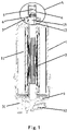
- the fuel pressure regulator and fuel filter assembly of the present utility model comprises a housing 1, a filter element 2, a cover plate 3, a rear cover 4, a spring 5, a seal 6 and a fixing ring 7.
- the housing 1 has an accommodating cavity 11 and a connecting end 12, the connecting end 12 having a fuel channel 13 in communication with the accommodating cavity 11.
- the filter element 2 is located in the accommodating cavity 11 of the housing 1.
- the cover plate 3 is located at one end of the housing 1, and is provided with a fuel inlet 31 and a fuel outlet 32.
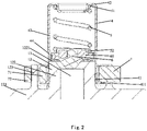
- the rear cover 4 is hollow inside; one end thereof is an opening end 41, the other end being a spring seat 42, and an opening 44 is provided on a sidewall 43 of the rear cover 4; the opening end 41 of the rear cover 4 is connected to the connecting end 12 of the housing 1.
- the spring 5 is located in the rear cover 4, and a first end 51 of the spring 5 is fixed to the spring seat 42 of the rear cover 4.
- the seal 6 is located in the rear cover 4, and a second end 52 of the spring 5 is pressed against the seal 6; when fuel pressure in the housing 1 is no greater than a spring preload, the seal 6 is pressed tightly against the connecting end 12 of the housing 1 and closes the fuel channel, but when fuel pressure in the housing is greater than the spring preload, fuel will push the seal 6, so that a gap forms between the seal 6 and the connecting end 12, and surplus fuel will return to a fuel storage box of a fuel pump directly via the opening 44 in the sidewall 43 of the rear cover 4.
- the fixing ring 7 fits the rear cover 4 to fix the rear cover 4 to the connecting end 12 of the housing 1, and the fixing ring 7 is welded by laser to the connecting end 12.
- the structure is simple and the cost is low; moreover, the fixing ring 7 is welded by laser to the connecting end 12 of the housing 1 so as to fix the rear cover 4 to the housing 1, there is no secondary injection molding, and fuel leakage is avoided.
- the connecting end 12 of the housing 1 has an end wall 121, a sealing part 122 protruding from the end wall 121, and a welding part 123.
- the fuel channel 13 runs through the sealing part 122, the opening end 41 of the rear cover 4 is located outside the sealing part 122, and the opening end 41 has a bent part 411 formed by outward bending.
- the fixing ring 7 is located outside the rear cover 4 and presses against the bent part 411, and the fixing ring 7 is connected by laser welding to the welding part 123.
- the welding part 123 is disposed around the outside of the sealing part 122 and is separated from the sealing part 122 by a certain gap, and the fixing ring 7 has an inner ring part 71 and an outer ring part 72 which are spaced apart.
- the inner ring part 71 and the opening end 41 of the rear cover 4 are located between the sealing part 122 and the welding part 123.
- the welding part 123 is located between the inner ring part 71 and the outer ring part 72, and is welded by laser to the outer ring part 72.
- the sealing part 122 has a sealing face 1221.
- the seal 6 When fuel pressure in the housing 1 is no greater than the spring preload, the seal 6 is pressed tightly against the sealing face 1221 and thereby closes the fuel channel 13.
- fuel pressure in the housing is greater than the spring preload, fuel pushes the seal 6 upwards by a certain distance, and a certain gap forms between the seal 6 and the sealing face 1221; fuel flows through the gap, and returns to the fuel storage box of the fuel pump through the opening 44 in the sidewall 43 of the rear cover 4.
- the seal 6 is fluororubber, with a metal framework 61 injection molded therein, to guarantee strength requirements of the seal 6.
- a grounding bolt 8 and a grounding spring 9 are disposed in the cover plate 3, and used to eliminate static electricity.
Landscapes
- Engineering & Computer Science (AREA)
- General Engineering & Computer Science (AREA)
- Chemical & Material Sciences (AREA)
- Mechanical Engineering (AREA)
- Combustion & Propulsion (AREA)
- Chemical Kinetics & Catalysis (AREA)
- Fuel-Injection Apparatus (AREA)
Description
- The present utility model relates to a vehicle fuel system, in particular an assembly comprising a fuel pressure regulator and a fuel filter.
- In the current market, a fuel pressure regulator and a fuel filter are generally integrated together by secondary injection molding, wherein the fuel pressure regulator comprises a body, a rear cover which fits the body, a valve seat, a spring, a diaphragm, a seal and an O-ring, wherein the valve seat has an accommodating cavity and a through-hole running through the accommodating cavity, the spring is disposed in the accommodating cavity with one end pressed against the valve seat and another end fixed to the rear cover, the diaphragm is located between the body and the valve seat and is welded to the body and the valve seat, an opening aligned with the through-hole of the valve seat is provided in the diaphragm in a middle position, the seal is fixed to the body, and the seal cooperates with an opening of the valve seat. When fuel pressure is higher than a standard value, highpressure fuel will push the valve seat via the diaphragm, the spring will be compressed, and fuel will return to a fuel storage box of a fuel pump via the through-hole of the valve seat and an opening in the rear cover. When fuel pressure is lower than a standard value, the spring pushes against and holds the valve seat in place, the valve seat and the seal cooperate to form a seal, and fuel return stops. The O-ring is located in a groove on the outermost side of the body, and is used to form a seal with an injection molded housing.
-
DE 19711531 A1 comprises a fuel filter housing, a fuel filter, being located in the fuel filter housing, and a fuel pressure regulator. The fuel filter housing comprises a fuel inlet and two fuel outlets. One fuel outlet directs previously filtered fuel to a combustion engine. The other fuel outlet directs fuel back to a fuel tank in the case the fuel pressure regulator opens a fuel channel. The fuel pressure regulator opens the fuel channel, if the fuel pressure exceeds a certain fuel pressure. In a first embodiment the fuel pressure regulator is detachable fixed to the housing. In a second embodiment the fuel pressure regulator is integrated into the fuel filter housing. -
EP 0 863 304 A1 comprises a fuel filter housing, a fuel filter, being located in the fuel filter housing, and a fuel pressure regulator. The fuel filter housing is attached to an electrical fuel pump. The fuel pressure regulator is attached to the fuel filter housing and regulated the pressure of the fuel flow directed to a combustion engine. - However, the problem of fuel leakage still occurs often at the joint between the housing formed by secondary injection molding and the fuel pressure regulator; moreover, the fuel pressure regulator has a complex structure and a high cost.
- The object of the present utility model is to provide a fuel pressure regulator and fuel filter assembly, which has a simple structure and a low cost, and solves the problem of fuel leakage.
- A fuel pressure regulator and fuel filter assembly provided in the present utility model comprises: a housing, having an accommodating cavity and a connecting end, the connecting end having a fuel channel in communication with the accommodating cavity; a filter element, located in the accommodating cavity of the housing; a cover plate, located at one end of the housing, the cover plate being provided with a fuel inlet and a fuel outlet; a rear cover, being hollow inside, with one end being an opening end and another end being a spring seat, and an opening being provided in a sidewall of the rear cover, the opening end of the rear cover being connected to the connecting end of the housing; a spring, being located in the rear cover, a first end of the spring being pressed against the spring seat of the rear cover; a seal, being located in the rear cover, with a second end of the spring being pressed against the seal, wherein when fuel pressure in the housing is no greater than a spring preload, the seal is pressed tightly against the connecting end of the housing and closes the fuel channel; and a fixing ring, which fits the rear cover to fix the rear cover to the connecting end of the housing, the fixing ring being welded by laser to the connecting end.
- The connecting end of the housing has an end wall, a sealing part protruding from the end wall, and a welding part; the fuel channel runs through the sealing part, the opening end of the rear cover is located outside the sealing part, and the opening end has a bent part formed by outward bending; the fixing ring is located outside the rear cover and presses against the bent part, and the fixing ring is connected by laser welding to the welding part.
- Preferably, the welding part is disposed around the outside of the sealing part and is separated from the sealing part by a certain gap, and the fixing ring has an inner ring part and an outer ring part which are spaced apart; the inner ring part and the opening end of the rear cover are located between the sealing part and the welding part; the welding part is located between the inner ring part and the outer ring part, and is welded by laser to the outer ring part.
- Preferably, the sealing part has a sealing face; when fuel pressure in the housing is no greater than the spring preload, the seal is pressed tightly against the sealing face and thereby closes the fuel channel.
- Preferably, the seal is fluororubber, with a metal framework injection molded therein.
- Preferably, a grounding bolt and a grounding spring are disposed in the cover plate.
- Compared with the prior art, since the rear cover, and the spring and seal located in the rear cover, cooperate with the connecting end of the housing to achieve regulation of fuel pressure at one end of the assembly, the structure is simple and the cost is low. Moreover, the fixing ring is welded by laser to the connecting end of the housing so as to fix the rear cover to the housing; this design has no secondary injection molding, and fuel leakage is avoided.
- The accompanying drawings, which form part of the present application, are intended to furnish deeper understanding of the present utility model. Schematic embodiments of the present utility model, and descriptions thereof, are intended to explain the present utility model, and do not constitute an improper limitation thereof. In the drawings:
-
Fig. 1 is a sectional view of the fuel pressure regulator and fuel filter assembly of the present utility model. -
Fig. 2 is an enlarged view of region A infig. 1 . -
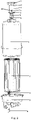
Fig. 3 is an exploded view of the fuel pressure regulator and fuel filter assembly of the present utility model. - Referring to
fig. 1 , the fuel pressure regulator and fuel filter assembly of the present utility model comprises ahousing 1, afilter element 2, acover plate 3, arear cover 4, aspring 5, aseal 6 and a fixing ring 7. Thehousing 1 has anaccommodating cavity 11 and a connectingend 12, the connectingend 12 having afuel channel 13 in communication with theaccommodating cavity 11. Thefilter element 2 is located in theaccommodating cavity 11 of thehousing 1. Thecover plate 3 is located at one end of thehousing 1, and is provided with afuel inlet 31 and afuel outlet 32. - Referring to
figs. 2 and3 , therear cover 4 is hollow inside; one end thereof is anopening end 41, the other end being aspring seat 42, and anopening 44 is provided on asidewall 43 of therear cover 4; theopening end 41 of therear cover 4 is connected to the connectingend 12 of thehousing 1. Thespring 5 is located in therear cover 4, and afirst end 51 of thespring 5 is fixed to thespring seat 42 of therear cover 4. Theseal 6 is located in therear cover 4, and asecond end 52 of thespring 5 is pressed against theseal 6; when fuel pressure in thehousing 1 is no greater than a spring preload, theseal 6 is pressed tightly against the connectingend 12 of thehousing 1 and closes the fuel channel, but when fuel pressure in the housing is greater than the spring preload, fuel will push theseal 6, so that a gap forms between theseal 6 and the connectingend 12, and surplus fuel will return to a fuel storage box of a fuel pump directly via theopening 44 in thesidewall 43 of therear cover 4. The fixing ring 7 fits therear cover 4 to fix therear cover 4 to the connectingend 12 of thehousing 1, and the fixing ring 7 is welded by laser to the connectingend 12. Since therear cover 4, and thespring 5 andseal 6 located in therear cover 4, cooperate with the connectingend 12 of thehousing 1 to achieve regulation of fuel pressure at one end of the assembly, the structure is simple and the cost is low; moreover, the fixing ring 7 is welded by laser to the connectingend 12 of thehousing 1 so as to fix therear cover 4 to thehousing 1, there is no secondary injection molding, and fuel leakage is avoided. - The connecting
end 12 of thehousing 1 has anend wall 121, a sealingpart 122 protruding from theend wall 121, and awelding part 123. Thefuel channel 13 runs through the sealingpart 122, theopening end 41 of therear cover 4 is located outside the sealingpart 122, and theopening end 41 has abent part 411 formed by outward bending. The fixing ring 7 is located outside therear cover 4 and presses against thebent part 411, and the fixing ring 7 is connected by laser welding to thewelding part 123. - The
welding part 123 is disposed around the outside of the sealingpart 122 and is separated from the sealingpart 122 by a certain gap, and the fixing ring 7 has aninner ring part 71 and anouter ring part 72 which are spaced apart. Theinner ring part 71 and theopening end 41 of therear cover 4 are located between thesealing part 122 and thewelding part 123. Thewelding part 123 is located between theinner ring part 71 and theouter ring part 72, and is welded by laser to theouter ring part 72. - The sealing
part 122 has a sealingface 1221. When fuel pressure in thehousing 1 is no greater than the spring preload, theseal 6 is pressed tightly against the sealingface 1221 and thereby closes thefuel channel 13. When fuel pressure in the housing is greater than the spring preload, fuel pushes theseal 6 upwards by a certain distance, and a certain gap forms between theseal 6 and the sealingface 1221; fuel flows through the gap, and returns to the fuel storage box of the fuel pump through theopening 44 in thesidewall 43 of therear cover 4. - The
seal 6 is fluororubber, with ametal framework 61 injection molded therein, to guarantee strength requirements of theseal 6. - A
grounding bolt 8 and a grounding spring 9 are disposed in thecover plate 3, and used to eliminate static electricity.
Claims (5)
- A fuel pressure regulator and fuel filter assembly, comprising:a housing (1), having an accommodating cavity (11) and a connecting end (12), the connecting end (12) having a fuel channel (13) in communication with the accommodating cavity (11);a filter element (2), located in the accommodating cavity (11) of the housing (1);a cover plate (3), located at one end of the housing (1), the cover plate (3) being provided with a fuel inlet (31) and a fuel outlet (32);a rear cover (4), being hollow inside, with one end being an opening end (41) and another end being a spring seat (42), and an opening (44) being provided in a sidewall (43) of the rear cover (4), the opening end (41) of the rear cover (4) being connected to the connecting end (12) of the housing (1);a spring (5), being located in the rear cover (4), a first end (51) of the spring (5) being pressed against the spring seat (42) of the rear cover (4);a seal (6), being located in the rear cover (4), with a second end (52) of the spring (5) being pressed against the seal (6) , wherein when fuel pressure in the housing (1) is no greater than a spring (5) preload, the seal (6) is pressed tightly against the connecting end (12) of the housing (1) and closes the fuel channel (13); and characterized bya fixing ring (7), which fits the rear cover (4) to fix the rear cover (4) to the connecting end (12) of the housing (1), the fixing ring (7) being welded by laser to the connecting end (12), wherebythe connecting end (12) of the housing (1) has an end wall (121), a sealing part (122) protruding from the end wall (121), and a welding part (123); the fuel channel (13) runs through the sealing part (122), the opening end (41) of the rear cover (4) is located outside the sealing part (122), and the opening end (41) has a bent part (411) formed by outward bending; the fixing ring (7) is located outside the rear cover (4) and presses against the bent part (411), and the fixing ring (7) is connected by laser welding to the welding part (123).
- The fuel pressure regulator and fuel filter assembly as claimed in claim 1, characterized in that the welding part (123) is disposed around the outside of the sealing part (122) and is separated from the sealing part (122) by a certain gap, and the fixing ring (7) has an inner ring part (71) and an outer ring part (72) which are spaced apart; the inner ring part (71) and the opening end (41) of the rear cover (4) are located between the sealing part (122) and the welding part (123); the welding part (123) is located between the inner ring part (71) and the outer ring part (72), and is welded by laser to the outer ring part (72).
- The fuel pressure regulator and fuel filter assembly as claimed in claim 1, characterized in that the sealing part (122) has a sealing face (1221); when fuel pressure in the housing (1) is no greater than the spring preload, the seal (6) is pressed tightly against the sealing face (1221) and thereby closes the fuel channel (13).
- The fuel pressure regulator and fuel filter assembly as claimed in claim 1, characterized in that the seal (6) is fluororubber, with a metal framework injection molded therein.
- The fuel pressure regulator and fuel filter assembly as claimed in claim 1, characterized in that a grounding bolt (8) and a grounding spring (9) are disposed in the cover plate (3).
Applications Claiming Priority (2)
| Application Number | Priority Date | Filing Date | Title |
|---|---|---|---|
| CN201621113526.1U CN206054146U (en) | 2016-10-11 | 2016-10-11 | Fuel pressure regulator and fuel filter device assembly |
| PCT/EP2017/075650 WO2018069233A1 (en) | 2016-10-11 | 2017-10-09 | Fuel pressure regulator and fuel filter assembly |
Publications (2)
| Publication Number | Publication Date |
|---|---|
| EP3526465A1 EP3526465A1 (en) | 2019-08-21 |
| EP3526465B1 true EP3526465B1 (en) | 2022-08-17 |
Family
ID=58363966
Family Applications (1)
| Application Number | Title | Priority Date | Filing Date |
|---|---|---|---|
| EP17787137.3A Active EP3526465B1 (en) | 2016-10-11 | 2017-10-09 | Fuel pressure regulator and fuel filter assembly |
Country Status (6)
| Country | Link |
|---|---|
| US (1) | US10662912B2 (en) |
| EP (1) | EP3526465B1 (en) |
| JP (1) | JP6780101B2 (en) |
| KR (1) | KR102196137B1 (en) |
| CN (1) | CN206054146U (en) |
| WO (1) | WO2018069233A1 (en) |
Families Citing this family (4)
| Publication number | Priority date | Publication date | Assignee | Title |
|---|---|---|---|---|
| CN107061078A (en) * | 2017-05-16 | 2017-08-18 | 太平洋电子(昆山)有限公司 | A kind of fuel pressure regulator |
| US10828584B2 (en) * | 2018-11-13 | 2020-11-10 | Hamilton Sundstrand Corporation | Fuel filter element electrical grounding |
| USD1072179S1 (en) * | 2023-03-10 | 2025-04-22 | Qingdao Ecopure Filter Co., Ltd. | Filter cartridge |
| CN117287720B (en) * | 2023-10-30 | 2025-09-02 | 重庆红江机械有限责任公司 | A pre-combustion chamber gas nozzle |
Family Cites Families (10)
| Publication number | Priority date | Publication date | Assignee | Title |
|---|---|---|---|---|
| US4011848A (en) | 1975-08-15 | 1977-03-15 | Chrysler Corporation | Fuel filter and roll-over valve |
| JPH10141159A (en) * | 1996-11-14 | 1998-05-26 | Unisia Jecs Corp | Fuel supply device |
| IT1290007B1 (en) * | 1997-03-03 | 1998-10-19 | Bitron Spa | FUEL INTAKE AND DELIVERY UNIT TO AN ENGINE, IN PARTICULAR FOR MOTOR VEHICLES |
| DE19711531C2 (en) * | 1997-03-20 | 1999-04-15 | Walter Schiffer | Fuel filter with pressure control valve |
| TW371699B (en) * | 1997-12-08 | 1999-10-11 | Mitsubishi Electric Corp | Fuel supply apparatus |
| US6158975A (en) * | 1998-09-24 | 2000-12-12 | Walbro Corporation | Fuel pump module |
| DE10019784A1 (en) * | 2000-04-20 | 2001-10-25 | Bosch Gmbh Robert | Fluid filter for fuel tank has filter housing with upper and lower sections consisting of plastic, and metal pressure regulator housing injected into central passage in top section of filter housing |
| DE10242872A1 (en) * | 2002-09-14 | 2004-03-25 | Mann + Hummel Gmbh | Valve in a filter |
| KR101135372B1 (en) * | 2009-10-20 | 2012-04-17 | 현담산업 주식회사 | Structure of Modulized Fuel Filter |
| CN104067036B (en) * | 2012-01-23 | 2016-09-28 | 大金工业株式会社 | Oil seal for automobile |
-
2016
- 2016-10-11 CN CN201621113526.1U patent/CN206054146U/en active Active
-
2017
- 2017-10-09 JP JP2019519403A patent/JP6780101B2/en active Active
- 2017-10-09 WO PCT/EP2017/075650 patent/WO2018069233A1/en not_active Ceased
- 2017-10-09 KR KR1020197012313A patent/KR102196137B1/en active Active
- 2017-10-09 EP EP17787137.3A patent/EP3526465B1/en active Active
- 2017-10-09 US US16/340,362 patent/US10662912B2/en active Active
Also Published As
| Publication number | Publication date |
|---|---|
| JP6780101B2 (en) | 2020-11-04 |
| CN206054146U (en) | 2017-03-29 |
| JP2019531437A (en) | 2019-10-31 |
| KR102196137B1 (en) | 2020-12-29 |
| WO2018069233A1 (en) | 2018-04-19 |
| EP3526465A1 (en) | 2019-08-21 |
| US20190242342A1 (en) | 2019-08-08 |
| US10662912B2 (en) | 2020-05-26 |
| KR20190052147A (en) | 2019-05-15 |
Similar Documents
| Publication | Publication Date | Title |
|---|---|---|
| EP3526465B1 (en) | Fuel pressure regulator and fuel filter assembly | |
| US5413077A (en) | Non-return fuel system with fuel pressure vacuum response | |
| US20160265494A1 (en) | Fuel supply device | |
| RU2659118C1 (en) | Fuel filter with device for additive release | |
| US20160245246A1 (en) | Fuel supply device | |
| US6306292B1 (en) | Fuel filter with internal pressure regulator | |
| CN110985213B (en) | Differential pressure type self-adjusting valve | |
| CN110593984B (en) | Filter | |
| CA2483179C (en) | Fuel return valve | |
| ITRM20060225A1 (en) | DERIVATION PRESSURE REGULATOR | |
| CN201786509U (en) | Fuel filter integrated with pressure regulating valve | |
| CN212389816U (en) | A dynamic balance control valve | |
| CN210049977U (en) | High leakproofness's filter and fuel pump assembly | |
| CN210623009U (en) | Pulse oil pump | |
| CN222316089U (en) | Pre-solenoid valve and water purifier | |
| US8397698B2 (en) | Composite fuel pump cartridge and fuel tank assembly | |
| CN223298552U (en) | Electronic atomizing device | |
| CN220302242U (en) | High-pressure fuel pump with sealing structure | |
| US10781776B2 (en) | Overmolded plug and method | |
| CN210599232U (en) | Fuel pump assembly structure | |
| JP5666331B2 (en) | Fuel supply device | |
| CN203231018U (en) | Water inlet pipe assembly and non-return water tank applying same | |
| CN110553069A (en) | Fluid pressure stabilizing valve | |
| CN210859000U (en) | Fuel pump with integrated pump body assembly and motor | |
| CN211819892U (en) | Straight-through pressure regulator for fuel pump |
Legal Events
| Date | Code | Title | Description |
|---|---|---|---|
| STAA | Information on the status of an ep patent application or granted ep patent |
Free format text: STATUS: UNKNOWN |
|
| STAA | Information on the status of an ep patent application or granted ep patent |
Free format text: STATUS: THE INTERNATIONAL PUBLICATION HAS BEEN MADE |
|
| PUAI | Public reference made under article 153(3) epc to a published international application that has entered the european phase |
Free format text: ORIGINAL CODE: 0009012 |
|
| STAA | Information on the status of an ep patent application or granted ep patent |
Free format text: STATUS: REQUEST FOR EXAMINATION WAS MADE |
|
| 17P | Request for examination filed |
Effective date: 20190513 |
|
| AK | Designated contracting states |
Kind code of ref document: A1 Designated state(s): AL AT BE BG CH CY CZ DE DK EE ES FI FR GB GR HR HU IE IS IT LI LT LU LV MC MK MT NL NO PL PT RO RS SE SI SK SM TR |
|
| RAP1 | Party data changed (applicant data changed or rights of an application transferred) |
Owner name: VITESCO TECHNOLOGIES GMBH |
|
| STAA | Information on the status of an ep patent application or granted ep patent |
Free format text: STATUS: EXAMINATION IS IN PROGRESS |
|
| 17Q | First examination report despatched |
Effective date: 20200415 |
|
| RAP1 | Party data changed (applicant data changed or rights of an application transferred) |
Owner name: VITESCO TECHNOLOGIES GMBH |
|
| RAP3 | Party data changed (applicant data changed or rights of an application transferred) |
Owner name: VITESCO TECHNOLOGIES GMBH |
|
| GRAP | Despatch of communication of intention to grant a patent |
Free format text: ORIGINAL CODE: EPIDOSNIGR1 |
|
| STAA | Information on the status of an ep patent application or granted ep patent |
Free format text: STATUS: GRANT OF PATENT IS INTENDED |
|
| INTG | Intention to grant announced |
Effective date: 20220311 |
|
| GRAS | Grant fee paid |
Free format text: ORIGINAL CODE: EPIDOSNIGR3 |
|
| GRAA | (expected) grant |
Free format text: ORIGINAL CODE: 0009210 |
|
| STAA | Information on the status of an ep patent application or granted ep patent |
Free format text: STATUS: THE PATENT HAS BEEN GRANTED |
|
| AK | Designated contracting states |
Kind code of ref document: B1 Designated state(s): AL AT BE BG CH CY CZ DE DK EE ES FI FR GB GR HR HU IE IS IT LI LT LU LV MC MK MT NL NO PL PT RO RS SE SI SK SM TR |
|
| REG | Reference to a national code |
Ref country code: CH Ref legal event code: EP |
|
| REG | Reference to a national code |
Ref country code: DE Ref legal event code: R096 Ref document number: 602017060782 Country of ref document: DE |
|
| REG | Reference to a national code |
Ref country code: IE Ref legal event code: FG4D |
|
| REG | Reference to a national code |
Ref country code: AT Ref legal event code: REF Ref document number: 1512348 Country of ref document: AT Kind code of ref document: T Effective date: 20220915 |
|
| REG | Reference to a national code |
Ref country code: NL Ref legal event code: MP Effective date: 20220817 |
|
| REG | Reference to a national code |
Ref country code: LT Ref legal event code: MG9D |
|
| PG25 | Lapsed in a contracting state [announced via postgrant information from national office to epo] |
Ref country code: SE Free format text: LAPSE BECAUSE OF FAILURE TO SUBMIT A TRANSLATION OF THE DESCRIPTION OR TO PAY THE FEE WITHIN THE PRESCRIBED TIME-LIMIT Effective date: 20220817 Ref country code: RS Free format text: LAPSE BECAUSE OF FAILURE TO SUBMIT A TRANSLATION OF THE DESCRIPTION OR TO PAY THE FEE WITHIN THE PRESCRIBED TIME-LIMIT Effective date: 20220817 Ref country code: PT Free format text: LAPSE BECAUSE OF FAILURE TO SUBMIT A TRANSLATION OF THE DESCRIPTION OR TO PAY THE FEE WITHIN THE PRESCRIBED TIME-LIMIT Effective date: 20221219 Ref country code: NO Free format text: LAPSE BECAUSE OF FAILURE TO SUBMIT A TRANSLATION OF THE DESCRIPTION OR TO PAY THE FEE WITHIN THE PRESCRIBED TIME-LIMIT Effective date: 20221117 Ref country code: NL Free format text: LAPSE BECAUSE OF FAILURE TO SUBMIT A TRANSLATION OF THE DESCRIPTION OR TO PAY THE FEE WITHIN THE PRESCRIBED TIME-LIMIT Effective date: 20220817 Ref country code: LV Free format text: LAPSE BECAUSE OF FAILURE TO SUBMIT A TRANSLATION OF THE DESCRIPTION OR TO PAY THE FEE WITHIN THE PRESCRIBED TIME-LIMIT Effective date: 20220817 Ref country code: LT Free format text: LAPSE BECAUSE OF FAILURE TO SUBMIT A TRANSLATION OF THE DESCRIPTION OR TO PAY THE FEE WITHIN THE PRESCRIBED TIME-LIMIT Effective date: 20220817 Ref country code: FI Free format text: LAPSE BECAUSE OF FAILURE TO SUBMIT A TRANSLATION OF THE DESCRIPTION OR TO PAY THE FEE WITHIN THE PRESCRIBED TIME-LIMIT Effective date: 20220817 |
|
| REG | Reference to a national code |
Ref country code: AT Ref legal event code: MK05 Ref document number: 1512348 Country of ref document: AT Kind code of ref document: T Effective date: 20220817 |
|
| PG25 | Lapsed in a contracting state [announced via postgrant information from national office to epo] |
Ref country code: PL Free format text: LAPSE BECAUSE OF FAILURE TO SUBMIT A TRANSLATION OF THE DESCRIPTION OR TO PAY THE FEE WITHIN THE PRESCRIBED TIME-LIMIT Effective date: 20220817 Ref country code: IS Free format text: LAPSE BECAUSE OF FAILURE TO SUBMIT A TRANSLATION OF THE DESCRIPTION OR TO PAY THE FEE WITHIN THE PRESCRIBED TIME-LIMIT Effective date: 20221217 Ref country code: HR Free format text: LAPSE BECAUSE OF FAILURE TO SUBMIT A TRANSLATION OF THE DESCRIPTION OR TO PAY THE FEE WITHIN THE PRESCRIBED TIME-LIMIT Effective date: 20220817 Ref country code: GR Free format text: LAPSE BECAUSE OF FAILURE TO SUBMIT A TRANSLATION OF THE DESCRIPTION OR TO PAY THE FEE WITHIN THE PRESCRIBED TIME-LIMIT Effective date: 20221118 |
|
| PG25 | Lapsed in a contracting state [announced via postgrant information from national office to epo] |
Ref country code: SM Free format text: LAPSE BECAUSE OF FAILURE TO SUBMIT A TRANSLATION OF THE DESCRIPTION OR TO PAY THE FEE WITHIN THE PRESCRIBED TIME-LIMIT Effective date: 20220817 Ref country code: RO Free format text: LAPSE BECAUSE OF FAILURE TO SUBMIT A TRANSLATION OF THE DESCRIPTION OR TO PAY THE FEE WITHIN THE PRESCRIBED TIME-LIMIT Effective date: 20220817 Ref country code: ES Free format text: LAPSE BECAUSE OF FAILURE TO SUBMIT A TRANSLATION OF THE DESCRIPTION OR TO PAY THE FEE WITHIN THE PRESCRIBED TIME-LIMIT Effective date: 20220817 Ref country code: DK Free format text: LAPSE BECAUSE OF FAILURE TO SUBMIT A TRANSLATION OF THE DESCRIPTION OR TO PAY THE FEE WITHIN THE PRESCRIBED TIME-LIMIT Effective date: 20220817 Ref country code: CZ Free format text: LAPSE BECAUSE OF FAILURE TO SUBMIT A TRANSLATION OF THE DESCRIPTION OR TO PAY THE FEE WITHIN THE PRESCRIBED TIME-LIMIT Effective date: 20220817 Ref country code: AT Free format text: LAPSE BECAUSE OF FAILURE TO SUBMIT A TRANSLATION OF THE DESCRIPTION OR TO PAY THE FEE WITHIN THE PRESCRIBED TIME-LIMIT Effective date: 20220817 |
|
| REG | Reference to a national code |
Ref country code: DE Ref legal event code: R097 Ref document number: 602017060782 Country of ref document: DE |
|
| PG25 | Lapsed in a contracting state [announced via postgrant information from national office to epo] |
Ref country code: SK Free format text: LAPSE BECAUSE OF FAILURE TO SUBMIT A TRANSLATION OF THE DESCRIPTION OR TO PAY THE FEE WITHIN THE PRESCRIBED TIME-LIMIT Effective date: 20220817 Ref country code: MC Free format text: LAPSE BECAUSE OF FAILURE TO SUBMIT A TRANSLATION OF THE DESCRIPTION OR TO PAY THE FEE WITHIN THE PRESCRIBED TIME-LIMIT Effective date: 20220817 Ref country code: EE Free format text: LAPSE BECAUSE OF FAILURE TO SUBMIT A TRANSLATION OF THE DESCRIPTION OR TO PAY THE FEE WITHIN THE PRESCRIBED TIME-LIMIT Effective date: 20220817 |
|
| REG | Reference to a national code |
Ref country code: CH Ref legal event code: PL |
|
| PLBE | No opposition filed within time limit |
Free format text: ORIGINAL CODE: 0009261 |
|
| STAA | Information on the status of an ep patent application or granted ep patent |
Free format text: STATUS: NO OPPOSITION FILED WITHIN TIME LIMIT |
|
| REG | Reference to a national code |
Ref country code: BE Ref legal event code: MM Effective date: 20221031 |
|
| PG25 | Lapsed in a contracting state [announced via postgrant information from national office to epo] |
Ref country code: LU Free format text: LAPSE BECAUSE OF NON-PAYMENT OF DUE FEES Effective date: 20221009 Ref country code: AL Free format text: LAPSE BECAUSE OF FAILURE TO SUBMIT A TRANSLATION OF THE DESCRIPTION OR TO PAY THE FEE WITHIN THE PRESCRIBED TIME-LIMIT Effective date: 20220817 |
|
| P01 | Opt-out of the competence of the unified patent court (upc) registered |
Effective date: 20230530 |
|
| 26N | No opposition filed |
Effective date: 20230519 |
|
| GBPC | Gb: european patent ceased through non-payment of renewal fee |
Effective date: 20221117 |
|
| PG25 | Lapsed in a contracting state [announced via postgrant information from national office to epo] |
Ref country code: LI Free format text: LAPSE BECAUSE OF NON-PAYMENT OF DUE FEES Effective date: 20221031 Ref country code: FR Free format text: LAPSE BECAUSE OF NON-PAYMENT OF DUE FEES Effective date: 20221017 Ref country code: CH Free format text: LAPSE BECAUSE OF NON-PAYMENT OF DUE FEES Effective date: 20221031 |
|
| PG25 | Lapsed in a contracting state [announced via postgrant information from national office to epo] |
Ref country code: SI Free format text: LAPSE BECAUSE OF FAILURE TO SUBMIT A TRANSLATION OF THE DESCRIPTION OR TO PAY THE FEE WITHIN THE PRESCRIBED TIME-LIMIT Effective date: 20220817 |
|
| PG25 | Lapsed in a contracting state [announced via postgrant information from national office to epo] |
Ref country code: BE Free format text: LAPSE BECAUSE OF NON-PAYMENT OF DUE FEES Effective date: 20221031 |
|
| PG25 | Lapsed in a contracting state [announced via postgrant information from national office to epo] |
Ref country code: IE Free format text: LAPSE BECAUSE OF NON-PAYMENT OF DUE FEES Effective date: 20221009 Ref country code: GB Free format text: LAPSE BECAUSE OF NON-PAYMENT OF DUE FEES Effective date: 20221117 |
|
| PG25 | Lapsed in a contracting state [announced via postgrant information from national office to epo] |
Ref country code: HU Free format text: LAPSE BECAUSE OF FAILURE TO SUBMIT A TRANSLATION OF THE DESCRIPTION OR TO PAY THE FEE WITHIN THE PRESCRIBED TIME-LIMIT; INVALID AB INITIO Effective date: 20171009 |
|
| PG25 | Lapsed in a contracting state [announced via postgrant information from national office to epo] |
Ref country code: CY Free format text: LAPSE BECAUSE OF FAILURE TO SUBMIT A TRANSLATION OF THE DESCRIPTION OR TO PAY THE FEE WITHIN THE PRESCRIBED TIME-LIMIT Effective date: 20220817 |
|
| PG25 | Lapsed in a contracting state [announced via postgrant information from national office to epo] |
Ref country code: MK Free format text: LAPSE BECAUSE OF FAILURE TO SUBMIT A TRANSLATION OF THE DESCRIPTION OR TO PAY THE FEE WITHIN THE PRESCRIBED TIME-LIMIT Effective date: 20220817 Ref country code: IT Free format text: LAPSE BECAUSE OF FAILURE TO SUBMIT A TRANSLATION OF THE DESCRIPTION OR TO PAY THE FEE WITHIN THE PRESCRIBED TIME-LIMIT Effective date: 20220817 |
|
| PG25 | Lapsed in a contracting state [announced via postgrant information from national office to epo] |
Ref country code: TR Free format text: LAPSE BECAUSE OF FAILURE TO SUBMIT A TRANSLATION OF THE DESCRIPTION OR TO PAY THE FEE WITHIN THE PRESCRIBED TIME-LIMIT Effective date: 20220817 |
|
| PG25 | Lapsed in a contracting state [announced via postgrant information from national office to epo] |
Ref country code: BG Free format text: LAPSE BECAUSE OF FAILURE TO SUBMIT A TRANSLATION OF THE DESCRIPTION OR TO PAY THE FEE WITHIN THE PRESCRIBED TIME-LIMIT Effective date: 20220817 |
|
| PG25 | Lapsed in a contracting state [announced via postgrant information from national office to epo] |
Ref country code: MT Free format text: LAPSE BECAUSE OF FAILURE TO SUBMIT A TRANSLATION OF THE DESCRIPTION OR TO PAY THE FEE WITHIN THE PRESCRIBED TIME-LIMIT Effective date: 20220817 |
|
| REG | Reference to a national code |
Ref country code: DE Ref legal event code: R081 Ref document number: 602017060782 Country of ref document: DE Owner name: SCHAEFFLER TECHNOLOGIES AG & CO. KG, DE Free format text: FORMER OWNER: VITESCO TECHNOLOGIES GMBH, 93055 REGENSBURG, DE |
|
| PGFP | Annual fee paid to national office [announced via postgrant information from national office to epo] |
Ref country code: DE Payment date: 20251031 Year of fee payment: 9 |