EP3526450B1 - Hydraulic lash adjuster assembly sleeves - Google Patents
Hydraulic lash adjuster assembly sleeves Download PDFInfo
- Publication number
- EP3526450B1 EP3526450B1 EP17861294.1A EP17861294A EP3526450B1 EP 3526450 B1 EP3526450 B1 EP 3526450B1 EP 17861294 A EP17861294 A EP 17861294A EP 3526450 B1 EP3526450 B1 EP 3526450B1
- Authority
- EP
- European Patent Office
- Prior art keywords
- sleeves
- hla
- lifter
- sleeve
- cylindrical
- Prior art date
- Legal status (The legal status is an assumption and is not a legal conclusion. Google has not performed a legal analysis and makes no representation as to the accuracy of the status listed.)
- Active
Links
Images

Classifications
-
- F—MECHANICAL ENGINEERING; LIGHTING; HEATING; WEAPONS; BLASTING
- F01—MACHINES OR ENGINES IN GENERAL; ENGINE PLANTS IN GENERAL; STEAM ENGINES
- F01L—CYCLICALLY OPERATING VALVES FOR MACHINES OR ENGINES
- F01L1/00—Valve-gear or valve arrangements, e.g. lift-valve gear
- F01L1/20—Adjusting or compensating clearance
- F01L1/22—Adjusting or compensating clearance automatically, e.g. mechanically
- F01L1/24—Adjusting or compensating clearance automatically, e.g. mechanically by fluid means, e.g. hydraulically
-
- F—MECHANICAL ENGINEERING; LIGHTING; HEATING; WEAPONS; BLASTING
- F01—MACHINES OR ENGINES IN GENERAL; ENGINE PLANTS IN GENERAL; STEAM ENGINES
- F01L—CYCLICALLY OPERATING VALVES FOR MACHINES OR ENGINES
- F01L1/00—Valve-gear or valve arrangements, e.g. lift-valve gear
- F01L1/12—Transmitting gear between valve drive and valve
- F01L1/14—Tappets; Push rods
- F01L1/146—Push-rods
-
- F—MECHANICAL ENGINEERING; LIGHTING; HEATING; WEAPONS; BLASTING
- F01—MACHINES OR ENGINES IN GENERAL; ENGINE PLANTS IN GENERAL; STEAM ENGINES
- F01L—CYCLICALLY OPERATING VALVES FOR MACHINES OR ENGINES
- F01L1/00—Valve-gear or valve arrangements, e.g. lift-valve gear
- F01L1/20—Adjusting or compensating clearance
- F01L1/22—Adjusting or compensating clearance automatically, e.g. mechanically
- F01L1/24—Adjusting or compensating clearance automatically, e.g. mechanically by fluid means, e.g. hydraulically
- F01L2001/2427—Adjusting or compensating clearance automatically, e.g. mechanically by fluid means, e.g. hydraulically by means of an hydraulic adjusting device located between cam and push rod
-
- F—MECHANICAL ENGINEERING; LIGHTING; HEATING; WEAPONS; BLASTING
- F01—MACHINES OR ENGINES IN GENERAL; ENGINE PLANTS IN GENERAL; STEAM ENGINES
- F01L—CYCLICALLY OPERATING VALVES FOR MACHINES OR ENGINES
- F01L1/00—Valve-gear or valve arrangements, e.g. lift-valve gear
- F01L1/20—Adjusting or compensating clearance
- F01L1/22—Adjusting or compensating clearance automatically, e.g. mechanically
- F01L1/24—Adjusting or compensating clearance automatically, e.g. mechanically by fluid means, e.g. hydraulically
- F01L1/245—Hydraulic tappets
- F01L2001/256—Hydraulic tappets between cam and push rod
-
- F—MECHANICAL ENGINEERING; LIGHTING; HEATING; WEAPONS; BLASTING
- F01—MACHINES OR ENGINES IN GENERAL; ENGINE PLANTS IN GENERAL; STEAM ENGINES
- F01L—CYCLICALLY OPERATING VALVES FOR MACHINES OR ENGINES
- F01L2305/00—Valve arrangements comprising rollers
-
- F—MECHANICAL ENGINEERING; LIGHTING; HEATING; WEAPONS; BLASTING
- F01—MACHINES OR ENGINES IN GENERAL; ENGINE PLANTS IN GENERAL; STEAM ENGINES
- F01L—CYCLICALLY OPERATING VALVES FOR MACHINES OR ENGINES
- F01L2307/00—Preventing the rotation of tappets
-
- F—MECHANICAL ENGINEERING; LIGHTING; HEATING; WEAPONS; BLASTING
- F01—MACHINES OR ENGINES IN GENERAL; ENGINE PLANTS IN GENERAL; STEAM ENGINES
- F01L—CYCLICALLY OPERATING VALVES FOR MACHINES OR ENGINES
- F01L2820/00—Details on specific features characterising valve gear arrangements
- F01L2820/01—Absolute values
Definitions
- the present disclosure relates to a hydraulic lash adjuster assembly and, more particularly, to a set of sleeves that enable a hydraulic lash adjuster assembly to be used in multiple engine applications.
- Some internal combustion engines can utilize rocker arms to transfer rotational motion of cams to linear motion appropriate for opening and closing engine valves.
- Deactivating rocker arms can incorporate hydraulic lash adjuster (HLA) mechanisms into a lifter bore of an engine block that allow for selective activation and deactivation of the rocker arm.
- HLA hydraulic lash adjuster
- the size of the lifter bores for the HLA mechanisms can vary across different types of engines, thus requiring specially sized HLA mechanisms for each size of lifter bore.
- EP 1223310 A1 discloses a lifter assembly for an internal combustion engine, including an elongate sleeve having an upper radial wall portion provided with oil feed and oil bleed holes therethrough, through which oil respectively enters and exits the lifter assembly.
- An elongate, hollow lifter body is reciprocatingly disposed within the sleeve.
- valve lifter or tappet which includes a foot having a cam contact surface and an axial bore formed therein, a tappet body having a body portion with an axially extending hub for reception in the axial bore of the foot, and a bearing assembly positioned between the foot and the tappet body.
- the present invention is a set of hydraulic lash adjuster (HLA) sleeves configured to be received within a lifter bore of an engine block as it is defined in claim 1.
- the set of HLA sleeves includes a first cylindrical sleeve having an outer surface defining a first outer diameter, and an inner surface defining a first inner diameter, and a second cylindrical sleeve having an outer surface defining a second outer diameter, and an inner surface defining a second inner diameter.
- the first outer diameter is larger than the second outer diameter.
- One of the first and second cylindrical sleeves is configured to be chosen from the set of HLA sleeves to fit into a corresponding sized lifter bore, and the first and second inner diameters are equal and are each configured to receive a same lifter.
- the described set of HLA sleeves may include one or more of the following features: a third cylindrical sleeve having an outer surface defining a third outer diameter, and an inner surface defining a third inner diameter, wherein the second outer diameter is larger than the third outer diameter, wherein one of the first, second, and third cylindrical sleeves is configured to be chosen from the set of HLA sleeves to fit into a corresponding sized lifter bore, and wherein the first, second, and third inner diameters are equal and are each configured to receive a same lifter.
- the described set of HLA sleeves may include one or more of the following features: wherein the inner surface of the first and second cylindrical sleeves includes a first flat configured to engage a second flat formed on the same lifter to prevent rotation of the same lifter within the first and second cylindrical sleeves; an outer key extending outwardly from the outer surface of each of the first and second cylindrical sleeves, the outer key configured to be received by the engine block to prevent rotation of the first or second cylindrical sleeves within the lifter bore; wherein the inner surface of the first and second cylindrical sleeves includes a flat; and an inner key extending inwardly from the inner surface of each of the first and second cylindrical sleeves, the inner key configured to be received by the same lifter to prevent relative rotation of the same lifter within the first and second cylindrical sleeves.
- the described set of HLA sleeves may include one or more of the following features: an inner key extending inwardly from the inner surface of each of the first and second cylindrical sleeves, the inner key configured to be received by the same lifter to prevent relative rotation of the same lifter within the HLA sleeve; a hydraulic fluid port formed through each of the first and second cylindrical sleeves and configured to supply hydraulic fluid to the same lifter; and an annular groove formed in the inner surface of each of the first and second cylindrical sleeves, the annular groove in fluid communication with the hydraulic fluid port, the annular groove configured to supply hydraulic fluid to the same lifter.
- a hydraulic lash adjuster (HLA) roller lifter constructed in accordance to one example of the present disclosure is shown and generally identified at reference number 10.
- Roller lifter 10 is shown as part of a Type V valve train arrangement.
- a cam lobe 12 indirectly drives a first end of a rocker arm 14 with a push rod 16.
- the roller lifter may be a direct link between the cam lobe 12 and the rocker arm 14.
- a second end of the rocker arm 14 actuates a valve 20. As the cam lobe 12 rotates, the rocker arm 14 pivots about a fixed shaft 22.
- the roller lifter 10 generally includes a body 30, a leakdown assembly 32 received within the body 30, and a roller bearing 34 rotatably mounted to the body 30.
- the body 30 includes an outer peripheral surface 36 configured for sliding movement in a lifter bore 40 provided in a cylinder head or engine block 42 of an internal combustion engine 44 (see FIG. 2B ).
- roller lifter 10 is configured to be disposed within an HLA sleeve 50, which is configured for insertion into the lifter bore 40 formed in the engine block 42. In this way, HLA sleeve 50 can take up the annular space between roller lifter 10 and an oversized bore 40.
- HLA sleeve 50 may be part of a set 100 of HLA sleeves 50, 50', 50" each having the same inner diameter D6 to receive HLA roller lifter 10, but having different outer diameters (e.g., D1, D1', D1"). As illustrated, D1 is greater than D1', which is greater than D1". This enables the same roller lifter 10 to be installed into lifter bores (e.g., 40, 40', 40") having various diameters by selecting from the different sized HLA sleeves 50. As illustrated, the diameter of bore 40 is greater than the diameter of bore 40', which is greater than the diameter of bore 40". As such, a new roller lifter does not need to be designed and sized for each of the various sized lifter bores 40 that occur across multiple engine platforms.
- each HLA sleeve 50 includes a cylindrical or generally cylindrical wall or sleeve 56 having a thickness 'T', an outer surface 58 defining outer diameter D1 ( FIG. 2B ), and an inner surface 60 defining inner diameter D6.
- Inner surface 60 defines a receiving aperture 62 to receive HLA roller lifter 10.
- Thickness 'T' is defined such that outer diameter D1 is equal to or slightly larger than a diameter of bore 40, thereby ensuring an interference fit between HLA sleeve 50 and lifter bore 40 to facilitate preventing rotation of HLA sleeve 50 within lifter bore 40.
- an HLA sleeve 50 is selected with dimensions to take up the size difference between the lifter bore 40 and the roller lifter 10.
- HLA sleeve 50 can include an outer key 64 and an inner key 66.
- Outer key 64 is configured to be received within a slot (not shown) formed within lifter bore 40 to thereby prevent rotation of HLA sleeve 50 within lifter bore 40.
- outer key 64 can have a width D5 and a depth D7.
- Inner key 66 is configured to be received within a slot 67 formed in roller lifter 10 to thereby prevent rotation of roller lifter 10 within HLA sleeve 50.
- inner key 66 can have a height D2, a width D3, and a depth D4, and roller lifter slot 67 can have a width D8.
- width D8 is equal to or slightly larger than width D3.
- HLA sleeve 50 may be press-fit into bore 40 and can include an inner flat 70 (e.g., a flat surface) formed on inner surface 60 (see FIG. 5 ).
- the inner flat 70 is configured to engage a lifter flat 72 (e.g., a flat surface formed on lifter 10 to thereby prevent rotation of lifter 10 within HLA sleeve 50.
- a lifter flat 72 e.g., a flat surface formed on lifter 10 to thereby prevent rotation of lifter 10 within HLA sleeve 50.
- This enables HLA sleeve 50 to prevent rotation of lifter 10 without having to alter the round lifter bore 40 (e.g., forming shapes or flats in the bore 40).
- sleeve outer surface 58 may be formed with a rough texture to facilitate gripping the wall of lifter bore 40 and preventing rotation of HLA sleeve 50.
- HLA sleeve 50 and/or roller lifter 10 may have other complementary shapes or geometries configured to prevent rotation of roller lifter 10 within HLA sleeve (e.g., spheres, slots, etc.).
- the HLA sleeve 50 may have a first engaging structure therein (such as on an inner surface) and the roller lifter 10 may have a complementary second engaging structure thereon (such as on an outer surface) for mating with the first engaging structure.
- the first and second engaging structures can be keyed or mated to inhibit or preclude relative rotation of the roller lifter 10 within the HLA sleeve 50.
- the first and second engaging structures can comprise any suitable complementary geometries such as concave depressions and convex extensions, slots and grooves, and other configurations.
- One example method of assembling an internal combustion engine 44 includes providing an engine block 42 with at least one oversized bore 40.
- An HLA roller lifter 10 is provided having a predetermined diameter 'D' that is smaller than the diameter of the oversized bore.
- the size of bore 40 is determined, and one HLA sleeve 50 is selected from a set of HLA sleeves to take up the annular space between the roller lifter 10 and the wall defining lifter bore 40.
- the selected HLA sleeve 50 is chosen having an outer diameter D1 equal to or slightly greater than the diameter of the lifter bore 40.
- the HLA sleeve 50 is inserted (e.g., press-fit) into lifter bore 40, and roller lifter 10 is subsequently inserted into the selected HLA sleeve 50.
- roller lifter 10 may be inserted into HLA sleeve 50, and sleeve 50 is subsequently inserted into lifter bore 40.
- HLA sleeve 50 is fabricated with an interference fit with lifter bore 40 of 0.0025" or approximately 0.0025" when engine block 42 is fabricated from cast iron. In another implementation, HLA sleeve 50 is fabricated with an interference fit with bore 40 of 0.004" or approximately 0.004" when engine block 42 is fabricated from aluminum.
- the HLA sleeve set includes three HLA sleeves 50 having thicknesses 'T' of 1/16", 3132", and 1/8". In other implementations, the thicknesses 'T' are approximately 1/16", approximately 3/32", and approximately 1/8". Accordingly, this enables one HLA sleeve 50 of the set of sleeves 100 to fit within various sized lifter bores 40 of varied engines 44 while maintaining the strength of the engine blocks 42.
- roller lifter 10 has a diameter of between 24 mm and 40 mm or between approximately 24 mm and approximately 40 mm. In another implementation, roller lifter 10 has a diameter of between 26 mm and 32 mm or between approximately 26 mm and approximately 32 mm.
- thickness 'T', outer diameter D1, inner diameter D6 may have any suitable size to accommodate various sized roller lifters 10 and lifter bores 40.
- HLA sleeve 50 may include one or more oil channel or feed 68 ( FIG. 2 ) configured to supply oil or other hydraulic fluid from a source to the roller lifter 10.
- sleeve inner surface 60 may include an annular groove 74 formed therein and in fluid communication with the hydraulic fluid feed 68.
- the annular groove 74 can be configured to supply hydraulic fluid to the lifter 10 via a groove 76, and can extend around the entirety or only a portion of the circumference of sleeve inner surface 60.
- HLA sleeve 50 is fabricated from a centrifugally spun cast iron alloy of carbon-chrome and molybdenum featuring high tensile strength of 48,000 psi to 53,000 psi.
- HLA sleeve 50 may be fabricated from plastic, ductile iron, HSS steel stamping, hydroformed tubing, or any other suitable material/process that enables HLA sleeve 50 to function as described herein.
Landscapes
- Engineering & Computer Science (AREA)
- Mechanical Engineering (AREA)
- General Engineering & Computer Science (AREA)
- Valve-Gear Or Valve Arrangements (AREA)
Description
- The present disclosure relates to a hydraulic lash adjuster assembly and, more particularly, to a set of sleeves that enable a hydraulic lash adjuster assembly to be used in multiple engine applications.
- Some internal combustion engines can utilize rocker arms to transfer rotational motion of cams to linear motion appropriate for opening and closing engine valves. Deactivating rocker arms can incorporate hydraulic lash adjuster (HLA) mechanisms into a lifter bore of an engine block that allow for selective activation and deactivation of the rocker arm. However, the size of the lifter bores for the HLA mechanisms can vary across different types of engines, thus requiring specially sized HLA mechanisms for each size of lifter bore.
- In
US 2004/0194739 A1 there is disclosed a device for preventing axial rotation of a valve lifter; and in particular a sleeved anti-rotation guide which prevents rotation of a roller follower valve lifter in an internal combustion engine. -
EP 1223310 A1 discloses a lifter assembly for an internal combustion engine, including an elongate sleeve having an upper radial wall portion provided with oil feed and oil bleed holes therethrough, through which oil respectively enters and exits the lifter assembly. An elongate, hollow lifter body is reciprocatingly disposed within the sleeve. - In
US 6435150 B1 there is shown a valve lifter or tappet which includes a foot having a cam contact surface and an axial bore formed therein, a tappet body having a body portion with an axially extending hub for reception in the axial bore of the foot, and a bearing assembly positioned between the foot and the tappet body. - The background description provided herein is for the purpose of generally presenting the context of the disclosure. Work of the presently named inventors, to the extent it is described in this background section, as well as aspects of the description that may not otherwise qualify as prior art at the time of filing, are neither expressly nor impliedly admitted as prior art against the present disclosure.
- The present invention is a set of hydraulic lash adjuster (HLA) sleeves configured to be received within a lifter bore of an engine block as it is defined in claim 1. The set of HLA sleeves includes a first cylindrical sleeve having an outer surface defining a first outer diameter, and an inner surface defining a first inner diameter, and a second cylindrical sleeve having an outer surface defining a second outer diameter, and an inner surface defining a second inner diameter. The first outer diameter is larger than the second outer diameter. One of the first and second cylindrical sleeves is configured to be chosen from the set of HLA sleeves to fit into a corresponding sized lifter bore, and the first and second inner diameters are equal and are each configured to receive a same lifter.
- In addition to the foregoing, the described set of HLA sleeves may include one or more of the following features: a third cylindrical sleeve having an outer surface defining a third outer diameter, and an inner surface defining a third inner diameter, wherein the second outer diameter is larger than the third outer diameter, wherein one of the first, second, and third cylindrical sleeves is configured to be chosen from the set of HLA sleeves to fit into a corresponding sized lifter bore, and wherein the first, second, and third inner diameters are equal and are each configured to receive a same lifter.
- In addition to the foregoing, the described set of HLA sleeves may include one or more of the following features: wherein the inner surface of the first and second cylindrical sleeves includes a first flat configured to engage a second flat formed on the same lifter to prevent rotation of the same lifter within the first and second cylindrical sleeves; an outer key extending outwardly from the outer surface of each of the first and second cylindrical sleeves, the outer key configured to be received by the engine block to prevent rotation of the first or second cylindrical sleeves within the lifter bore; wherein the inner surface of the first and second cylindrical sleeves includes a flat; and an inner key extending inwardly from the inner surface of each of the first and second cylindrical sleeves, the inner key configured to be received by the same lifter to prevent relative rotation of the same lifter within the first and second cylindrical sleeves.
- In addition to the foregoing, the described set of HLA sleeves may include one or more of the following features: an inner key extending inwardly from the inner surface of each of the first and second cylindrical sleeves, the inner key configured to be received by the same lifter to prevent relative rotation of the same lifter within the HLA sleeve; a hydraulic fluid port formed through each of the first and second cylindrical sleeves and configured to supply hydraulic fluid to the same lifter; and an annular groove formed in the inner surface of each of the first and second cylindrical sleeves, the annular groove in fluid communication with the hydraulic fluid port, the annular groove configured to supply hydraulic fluid to the same lifter.
- The present disclosure will become more fully understood from the detailed description and the accompanying drawings, wherein:
-
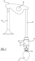
FIG. 1 is a roller lifter constructed in accordance to one example of the present disclosure and shown in an exemplary Type V valve train arrangement; -
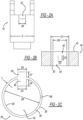
FIG. 2A is a roller lifter constructed in accordance to one example of the present disclosure; -
FIG. 2B is a cross-sectional view of an exemplary hydraulic lash adjuster (HLA) sleeve constructed in accordance to one example of the present disclosure and shown received in an exemplary engine block; -
FIG. 2C is a top view of the HLA sleeve ofFIG. 2B ; -
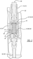
FIG. 3 is a cross-sectional view of a valve train arrangement having the HLA sleeve shown inFIG. 1 . in accordance to one example of the present disclosure; -
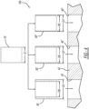
FIG. 4 illustrates a set of HLA sleeves in accordance to one example of the present disclosure; and -
FIG. 5 is a top view of an HLA sleeve and lifter in accordance to one example of the present disclosure. - With initial reference to
FIG. 1 , a hydraulic lash adjuster (HLA) roller lifter constructed in accordance to one example of the present disclosure is shown and generally identified atreference number 10.Roller lifter 10 is shown as part of a Type V valve train arrangement. However, it will be appreciated that while shown in a Type V arrangement, it is within the scope of the present disclosure for the various features described herein to be used in other arrangements. In this regard, the features described herein associated with thevalve train arrangement 10 can be suitable to a wide variety of applications. Acam lobe 12 indirectly drives a first end of arocker arm 14 with apush rod 16. It will be appreciated that in some configurations, such as an overhead cam, the roller lifter may be a direct link between thecam lobe 12 and therocker arm 14. A second end of therocker arm 14 actuates avalve 20. As thecam lobe 12 rotates, therocker arm 14 pivots about afixed shaft 22. - In the example implementation, the
roller lifter 10 generally includes abody 30, aleakdown assembly 32 received within thebody 30, and a roller bearing 34 rotatably mounted to thebody 30. Thebody 30 includes an outerperipheral surface 36 configured for sliding movement in alifter bore 40 provided in a cylinder head orengine block 42 of an internal combustion engine 44 (seeFIG. 2B ). As shown inFIGS. 2 and3 ,roller lifter 10 is configured to be disposed within anHLA sleeve 50, which is configured for insertion into thelifter bore 40 formed in theengine block 42. In this way,HLA sleeve 50 can take up the annular space betweenroller lifter 10 and anoversized bore 40. - Moreover, as shown in
FIG. 4 ,HLA sleeve 50 may be part of aset 100 ofHLA sleeves HLA roller lifter 10, but having different outer diameters (e.g., D1, D1', D1"). As illustrated, D1 is greater than D1', which is greater than D1". This enables thesame roller lifter 10 to be installed into lifter bores (e.g., 40, 40', 40") having various diameters by selecting from the different sizedHLA sleeves 50. As illustrated, the diameter ofbore 40 is greater than the diameter of bore 40', which is greater than the diameter ofbore 40". As such, a new roller lifter does not need to be designed and sized for each of the various sizedlifter bores 40 that occur across multiple engine platforms. - As illustrated in
FIGS. 2A - 2C , eachHLA sleeve 50 includes a cylindrical or generally cylindrical wall orsleeve 56 having a thickness 'T', anouter surface 58 defining outer diameter D1 (FIG. 2B ), and aninner surface 60 defining inner diameter D6.Inner surface 60 defines a receivingaperture 62 to receiveHLA roller lifter 10. Thickness 'T' is defined such that outer diameter D1 is equal to or slightly larger than a diameter ofbore 40, thereby ensuring an interference fit betweenHLA sleeve 50 and lifter bore 40 to facilitate preventing rotation ofHLA sleeve 50 withinlifter bore 40. As such, anHLA sleeve 50 is selected with dimensions to take up the size difference between thelifter bore 40 and theroller lifter 10. - In one arrangement shown in
FIGS. 2A - 2C ,HLA sleeve 50 can include anouter key 64 and aninner key 66.Outer key 64 is configured to be received within a slot (not shown) formed withinlifter bore 40 to thereby prevent rotation ofHLA sleeve 50 withinlifter bore 40. As shown inFIG. 2C ,outer key 64 can have a width D5 and a depth D7.Inner key 66 is configured to be received within aslot 67 formed inroller lifter 10 to thereby prevent rotation ofroller lifter 10 withinHLA sleeve 50. As shown inFIGS. 2A -2C , inner key 66 can have a height D2, a width D3, and a depth D4, androller lifter slot 67 can have a width D8. In one example, width D8 is equal to or slightly larger than width D3. - In alternative arrangements, rather than having
keys HLA sleeve 50 may be press-fit intobore 40 and can include an inner flat 70 (e.g., a flat surface) formed on inner surface 60 (seeFIG. 5 ). The inner flat 70 is configured to engage a lifter flat 72 (e.g., a flat surface formed onlifter 10 to thereby prevent rotation oflifter 10 withinHLA sleeve 50. This enablesHLA sleeve 50 to prevent rotation oflifter 10 without having to alter the round lifter bore 40 (e.g., forming shapes or flats in the bore 40). Moreover, sleeveouter surface 58 may be formed with a rough texture to facilitate gripping the wall of lifter bore 40 and preventing rotation ofHLA sleeve 50. - In other examples,
HLA sleeve 50 and/orroller lifter 10 may have other complementary shapes or geometries configured to prevent rotation ofroller lifter 10 within HLA sleeve (e.g., spheres, slots, etc.). In this regard, theHLA sleeve 50 may have a first engaging structure therein (such as on an inner surface) and theroller lifter 10 may have a complementary second engaging structure thereon (such as on an outer surface) for mating with the first engaging structure. The first and second engaging structures can be keyed or mated to inhibit or preclude relative rotation of theroller lifter 10 within theHLA sleeve 50. The first and second engaging structures can comprise any suitable complementary geometries such as concave depressions and convex extensions, slots and grooves, and other configurations. - One example method of assembling an
internal combustion engine 44 includes providing anengine block 42 with at least oneoversized bore 40. AnHLA roller lifter 10 is provided having a predetermined diameter 'D' that is smaller than the diameter of the oversized bore. The size ofbore 40 is determined, and oneHLA sleeve 50 is selected from a set of HLA sleeves to take up the annular space between theroller lifter 10 and the wall defining lifter bore 40. The selectedHLA sleeve 50 is chosen having an outer diameter D1 equal to or slightly greater than the diameter of the lifter bore 40. TheHLA sleeve 50 is inserted (e.g., press-fit) into lifter bore 40, androller lifter 10 is subsequently inserted into the selectedHLA sleeve 50. Alternatively,roller lifter 10 may be inserted intoHLA sleeve 50, andsleeve 50 is subsequently inserted into lifter bore 40. - In one implementation,
HLA sleeve 50 is fabricated with an interference fit with lifter bore 40 of 0.0025" or approximately 0.0025" whenengine block 42 is fabricated from cast iron. In another implementation,HLA sleeve 50 is fabricated with an interference fit withbore 40 of 0.004" or approximately 0.004" whenengine block 42 is fabricated from aluminum. - In one implementation, the HLA sleeve set includes three
HLA sleeves 50 having thicknesses 'T' of 1/16", 3132", and 1/8". In other implementations, the thicknesses 'T' are approximately 1/16", approximately 3/32", and approximately 1/8". Accordingly, this enables oneHLA sleeve 50 of the set ofsleeves 100 to fit within various sized lifter bores 40 ofvaried engines 44 while maintaining the strength of the engine blocks 42. In one implementation,roller lifter 10 has a diameter of between 24 mm and 40 mm or between approximately 24 mm and approximately 40 mm. In another implementation,roller lifter 10 has a diameter of between 26 mm and 32 mm or between approximately 26 mm and approximately 32 mm. However, it will be appreciated that thickness 'T', outer diameter D1, inner diameter D6 may have any suitable size to accommodate varioussized roller lifters 10 and lifter bores 40. - Moreover,
HLA sleeve 50 may include one or more oil channel or feed 68 (FIG. 2 ) configured to supply oil or other hydraulic fluid from a source to theroller lifter 10. Additionally, as shown inFIG. 3 , sleeveinner surface 60 may include anannular groove 74 formed therein and in fluid communication with thehydraulic fluid feed 68. Theannular groove 74 can be configured to supply hydraulic fluid to thelifter 10 via agroove 76, and can extend around the entirety or only a portion of the circumference of sleeveinner surface 60. - In some examples,
HLA sleeve 50 is fabricated from a centrifugally spun cast iron alloy of carbon-chrome and molybdenum featuring high tensile strength of 48,000 psi to 53,000 psi. Alternatively,HLA sleeve 50 may be fabricated from plastic, ductile iron, HSS steel stamping, hydroformed tubing, or any other suitable material/process that enablesHLA sleeve 50 to function as described herein. - The foregoing description of the examples has been provided for purposes of illustration and description. It is not intended to be exhaustive or to limit the disclosure.
Claims (9)
- A set (100) of hydraulic lash adjuster (HLA) sleeves configured to be received within a lifter bore (40, 40', 40") of an engine block (42), the set of HLA sleeves comprising:a first cylindrical sleeve (50) having an outer surface (58) defining a first outer diameter (D1), and an inner surface (60) defining a first inner diameter (D6);a second cylindrical sleeve (50') having an outer surface (58) defining a second outer diameter (D1'), and an inner surface (60) defining a second inner diameter (D6);characterized in that the first outer diameter is larger than the second outer diameter, wherein one of the first and second cylindrical sleeves is configured to be chosen from the set of HLA sleeves to fit into a corresponding sized lifter bore, andwherein the first and second inner diameters are equal and are each configured to receive a same lifter.
- The set of HLA sleeves of claim 1, further comprising a third cylindrical sleeve (50") having an outer surface (58) defining a third outer diameter (D1 "), and an inner surface (60) defining a third inner diameter (D6), wherein the second outer diameter is larger than the third outer diameter,wherein one of the first, second, and third cylindrical sleeves is configured to be chosen from the set of HLA sleeves to fit into a corresponding sized lifter bore,wherein the first, second, and third inner diameters are equal and are each configured to receive a same lifter.
- The set of HLA sleeves of claim 1, wherein the inner surface of the first and second cylindrical sleeves includes a first flat (70) configured to engage a second flat (72) formed on the same lifter to prevent rotation of the same lifter within the first and second cylindrical sleeves.
- The set of HLA sleeves of claim 1, further comprising an outer key (64) extending outwardly from the outer surface of each of the first and second cylindrical sleeves, the outer key configured to be received by the engine block to prevent rotation of the first or second cylindrical sleeves within the lifter bore.
- The set of HLA sleeves of claim 4, wherein the inner surface of the first and second cylindrical sleeves includes a flat (70).
- The set of HLA sleeves of claim 4, further comprising an inner key (66) extending inwardly from the inner surface of each of the first and second cylindrical sleeves, the inner key configured to be received by the same lifter to prevent relative rotation of the same lifter within the first and second cylindrical sleeves.
- The set of HLA sleeves of claim 1, further comprising an inner key (66) extending inwardly from the inner surface of each of the first and second cylindrical sleeves, the inner key configured to be received by the same lifter to prevent relative rotation of the same lifter within the HLA sleeve.
- The set of HLA sleeves of claim 1, further comprising a hydraulic fluid port (68) formed through each of the first and second cylindrical sleeves and configured to supply hydraulic fluid to the same lifter.
- The set of HLA sleeves of claim 8, further comprising an annular groove (74) formed in the inner surface of each of the first and second cylindrical sleeves, the annular groove in fluid communication with the hydraulic fluid port, the annular groove configured to supply hydraulic fluid to the same lifter.
Applications Claiming Priority (2)
| Application Number | Priority Date | Filing Date | Title |
|---|---|---|---|
| US201662409084P | 2016-10-17 | 2016-10-17 | |
| PCT/US2017/056842 WO2018075425A1 (en) | 2016-10-17 | 2017-10-17 | Hydraulic lash adjuster assembly sleeves |
Publications (3)
| Publication Number | Publication Date |
|---|---|
| EP3526450A1 EP3526450A1 (en) | 2019-08-21 |
| EP3526450A4 EP3526450A4 (en) | 2020-05-20 |
| EP3526450B1 true EP3526450B1 (en) | 2024-05-08 |
Family
ID=62019282
Family Applications (1)
| Application Number | Title | Priority Date | Filing Date |
|---|---|---|---|
| EP17861294.1A Active EP3526450B1 (en) | 2016-10-17 | 2017-10-17 | Hydraulic lash adjuster assembly sleeves |
Country Status (4)
| Country | Link |
|---|---|
| US (1) | US10690017B2 (en) |
| EP (1) | EP3526450B1 (en) |
| CN (1) | CN110073082A (en) |
| WO (1) | WO2018075425A1 (en) |
Families Citing this family (1)
| Publication number | Priority date | Publication date | Assignee | Title |
|---|---|---|---|---|
| US11236642B2 (en) | 2020-05-04 | 2022-02-01 | Caterpillar Inc. | Valve lifter anti-rotation device and valve lifter assembly in valve actuation system |
Family Cites Families (15)
| Publication number | Priority date | Publication date | Assignee | Title |
|---|---|---|---|---|
| US2237854A (en) * | 1934-06-04 | 1941-04-08 | Eaton Mfg Co | Compensating hydraulic valve tappet for internal combustion engines |
| JPS61167109A (en) * | 1985-01-18 | 1986-07-28 | Toyota Motor Corp | Mechanical valve lifter device for internal-combustion engine |
| US5263386A (en) * | 1992-11-24 | 1993-11-23 | General Motors Corporation | Roller cam follower guide |
| US6435150B1 (en) * | 2000-07-25 | 2002-08-20 | Daimlerchrysler Corporation | Offset tappet assembly |
| US6460499B1 (en) * | 2001-01-16 | 2002-10-08 | Tecumseh Products Company | Hydraulic lifter assembly |
| DE10225721A1 (en) * | 2001-06-25 | 2003-01-09 | Ina Schaeffler Kg | Method for fitting valve guide bridge to engine head block using clip fastening into prepared holes in the block |
| US6681734B2 (en) * | 2002-02-01 | 2004-01-27 | General Motors Corporation | Hydraulic cylinder deactivation with rotary sleeves |
| US7121244B2 (en) * | 2003-04-02 | 2006-10-17 | Delphi Technologies, Inc. | Anti-rotation guide for a roller follower valve lifter |
| DE102006059716A1 (en) * | 2006-12-18 | 2008-06-26 | Mahle International Gmbh | Non-rotating ram of a valve train |
| US20100000476A1 (en) * | 2008-07-07 | 2010-01-07 | Kunz Timothy W | Anti-Rotation Feature for an Engine Tappet |
| US8136494B2 (en) * | 2008-10-21 | 2012-03-20 | Ford Global Technologies, Llc | Lifter guide |
| TW201024552A (en) * | 2008-10-30 | 2010-07-01 | Powers Products Iii Llc | Carrier strip system and method for different diameter fasteners |
| US8851038B1 (en) * | 2008-12-09 | 2014-10-07 | Ed Iskenderian Racing Cams | Roller valve lifter |
| CN101832897B (en) * | 2010-05-12 | 2011-11-23 | 株洲市九洲四维实业有限公司 | Ground loading simulator of vertical wind power yawing reducer |
| US20170342868A1 (en) * | 2016-05-26 | 2017-11-30 | Hydrogen Engine Center | Apparatus, systems and methods for indexed hydraulic roller lifters |
-
2017
- 2017-10-17 WO PCT/US2017/056842 patent/WO2018075425A1/en not_active Ceased
- 2017-10-17 EP EP17861294.1A patent/EP3526450B1/en active Active
- 2017-10-17 CN CN201780076768.9A patent/CN110073082A/en active Pending
-
2019
- 2019-04-17 US US16/386,437 patent/US10690017B2/en active Active
Also Published As
| Publication number | Publication date |
|---|---|
| EP3526450A4 (en) | 2020-05-20 |
| WO2018075425A1 (en) | 2018-04-26 |
| CN110073082A (en) | 2019-07-30 |
| US10690017B2 (en) | 2020-06-23 |
| EP3526450A1 (en) | 2019-08-21 |
| US20190242276A1 (en) | 2019-08-08 |
Similar Documents
| Publication | Publication Date | Title |
|---|---|---|
| US10132208B2 (en) | Engine valve lifter oil flow control and anti-rotation feature | |
| US8534252B2 (en) | Concentric camshaft with varying wall geometry and method of assembly | |
| US7854215B2 (en) | Valve train with overload features | |
| US6347606B1 (en) | Valve operating system in internal combustion engine | |
| US6186102B1 (en) | Valve operating system for internal combustion engine | |
| JP6892868B2 (en) | Engine valve lifter with anti-rotation plug | |
| US5931133A (en) | Roller cam follower bearing shaft retention | |
| US10690016B2 (en) | Engine valve lifter having anti-rotation plug | |
| US9726270B2 (en) | Cam follower roller device, notably for a fuel injection pump | |
| US6467444B2 (en) | Valve operating system in internal combustion engine | |
| US10690017B2 (en) | Hydraulic lash adjuster assembly sleeves | |
| US8113163B2 (en) | Concentric camshaft and method of assembly | |
| US6347607B2 (en) | Valve operating system in internal combustion engine | |
| EP3018377B1 (en) | Bearing device and method of manufacturing the same | |
| US20180156078A1 (en) | Engine valve lifter oil flow control and anti-rotation feature | |
| EP3443206B1 (en) | Tappet with sliding inner cup | |
| US8096050B2 (en) | Double ballize camshaft assembly process | |
| EP3037632B1 (en) | Method for producing a hydraulic lash adjuster | |
| US8156910B2 (en) | Concentric camshaft and method of assembly | |
| WO2019129829A1 (en) | Engine valve lifter having anti-rotation plug | |
| WO2018098283A1 (en) | Engine valve lifter oil flow control and anti-rotation feature | |
| KR20200092886A (en) | Camshaft follower mechanism | |
| JPH1113441A (en) | Engine Valve Actuator |
Legal Events
| Date | Code | Title | Description |
|---|---|---|---|
| STAA | Information on the status of an ep patent application or granted ep patent |
Free format text: STATUS: THE INTERNATIONAL PUBLICATION HAS BEEN MADE |
|
| PUAI | Public reference made under article 153(3) epc to a published international application that has entered the european phase |
Free format text: ORIGINAL CODE: 0009012 |
|
| STAA | Information on the status of an ep patent application or granted ep patent |
Free format text: STATUS: REQUEST FOR EXAMINATION WAS MADE |
|
| 17P | Request for examination filed |
Effective date: 20190513 |
|
| AK | Designated contracting states |
Kind code of ref document: A1 Designated state(s): AL AT BE BG CH CY CZ DE DK EE ES FI FR GB GR HR HU IE IS IT LI LT LU LV MC MK MT NL NO PL PT RO RS SE SI SK SM TR |
|
| AX | Request for extension of the european patent |
Extension state: BA ME |
|
| DAV | Request for validation of the european patent (deleted) | ||
| DAX | Request for extension of the european patent (deleted) | ||
| A4 | Supplementary search report drawn up and despatched |
Effective date: 20200420 |
|
| RIC1 | Information provided on ipc code assigned before grant |
Ipc: F01L 1/14 20060101ALI20200414BHEP Ipc: F01L 1/24 20060101AFI20200414BHEP |
|
| STAA | Information on the status of an ep patent application or granted ep patent |
Free format text: STATUS: EXAMINATION IS IN PROGRESS |
|
| 17Q | First examination report despatched |
Effective date: 20220621 |
|
| P01 | Opt-out of the competence of the unified patent court (upc) registered |
Effective date: 20230521 |
|
| GRAP | Despatch of communication of intention to grant a patent |
Free format text: ORIGINAL CODE: EPIDOSNIGR1 |
|
| STAA | Information on the status of an ep patent application or granted ep patent |
Free format text: STATUS: GRANT OF PATENT IS INTENDED |
|
| INTG | Intention to grant announced |
Effective date: 20240223 |
|
| GRAS | Grant fee paid |
Free format text: ORIGINAL CODE: EPIDOSNIGR3 |
|
| GRAA | (expected) grant |
Free format text: ORIGINAL CODE: 0009210 |
|
| STAA | Information on the status of an ep patent application or granted ep patent |
Free format text: STATUS: THE PATENT HAS BEEN GRANTED |
|
| AK | Designated contracting states |
Kind code of ref document: B1 Designated state(s): AL AT BE BG CH CY CZ DE DK EE ES FI FR GB GR HR HU IE IS IT LI LT LU LV MC MK MT NL NO PL PT RO RS SE SI SK SM TR |
|
| REG | Reference to a national code |
Ref country code: GB Ref legal event code: FG4D |
|
| REG | Reference to a national code |
Ref country code: CH Ref legal event code: EP |
|
| REG | Reference to a national code |
Ref country code: DE Ref legal event code: R096 Ref document number: 602017081836 Country of ref document: DE |
|
| REG | Reference to a national code |
Ref country code: IE Ref legal event code: FG4D |
|
| REG | Reference to a national code |
Ref country code: LT Ref legal event code: MG9D |
|
| REG | Reference to a national code |
Ref country code: NL Ref legal event code: MP Effective date: 20240508 |
|
| PG25 | Lapsed in a contracting state [announced via postgrant information from national office to epo] |
Ref country code: IS Free format text: LAPSE BECAUSE OF FAILURE TO SUBMIT A TRANSLATION OF THE DESCRIPTION OR TO PAY THE FEE WITHIN THE PRESCRIBED TIME-LIMIT Effective date: 20240908 |
|
| PG25 | Lapsed in a contracting state [announced via postgrant information from national office to epo] |
Ref country code: BG Free format text: LAPSE BECAUSE OF FAILURE TO SUBMIT A TRANSLATION OF THE DESCRIPTION OR TO PAY THE FEE WITHIN THE PRESCRIBED TIME-LIMIT Effective date: 20240508 |
|
| PG25 | Lapsed in a contracting state [announced via postgrant information from national office to epo] |
Ref country code: HR Free format text: LAPSE BECAUSE OF FAILURE TO SUBMIT A TRANSLATION OF THE DESCRIPTION OR TO PAY THE FEE WITHIN THE PRESCRIBED TIME-LIMIT Effective date: 20240508 Ref country code: FI Free format text: LAPSE BECAUSE OF FAILURE TO SUBMIT A TRANSLATION OF THE DESCRIPTION OR TO PAY THE FEE WITHIN THE PRESCRIBED TIME-LIMIT Effective date: 20240508 |
|
| PG25 | Lapsed in a contracting state [announced via postgrant information from national office to epo] |
Ref country code: GR Free format text: LAPSE BECAUSE OF FAILURE TO SUBMIT A TRANSLATION OF THE DESCRIPTION OR TO PAY THE FEE WITHIN THE PRESCRIBED TIME-LIMIT Effective date: 20240809 |
|
| PG25 | Lapsed in a contracting state [announced via postgrant information from national office to epo] |
Ref country code: PT Free format text: LAPSE BECAUSE OF FAILURE TO SUBMIT A TRANSLATION OF THE DESCRIPTION OR TO PAY THE FEE WITHIN THE PRESCRIBED TIME-LIMIT Effective date: 20240909 |
|
| REG | Reference to a national code |
Ref country code: AT Ref legal event code: MK05 Ref document number: 1685158 Country of ref document: AT Kind code of ref document: T Effective date: 20240508 |
|
| PG25 | Lapsed in a contracting state [announced via postgrant information from national office to epo] |
Ref country code: NL Free format text: LAPSE BECAUSE OF FAILURE TO SUBMIT A TRANSLATION OF THE DESCRIPTION OR TO PAY THE FEE WITHIN THE PRESCRIBED TIME-LIMIT Effective date: 20240508 |
|
| PG25 | Lapsed in a contracting state [announced via postgrant information from national office to epo] |
Ref country code: ES Free format text: LAPSE BECAUSE OF FAILURE TO SUBMIT A TRANSLATION OF THE DESCRIPTION OR TO PAY THE FEE WITHIN THE PRESCRIBED TIME-LIMIT Effective date: 20240508 |
|
| PG25 | Lapsed in a contracting state [announced via postgrant information from national office to epo] |
Ref country code: AT Free format text: LAPSE BECAUSE OF FAILURE TO SUBMIT A TRANSLATION OF THE DESCRIPTION OR TO PAY THE FEE WITHIN THE PRESCRIBED TIME-LIMIT Effective date: 20240508 |
|
| PG25 | Lapsed in a contracting state [announced via postgrant information from national office to epo] |
Ref country code: PL Free format text: LAPSE BECAUSE OF FAILURE TO SUBMIT A TRANSLATION OF THE DESCRIPTION OR TO PAY THE FEE WITHIN THE PRESCRIBED TIME-LIMIT Effective date: 20240508 |
|
| PG25 | Lapsed in a contracting state [announced via postgrant information from national office to epo] |
Ref country code: LV Free format text: LAPSE BECAUSE OF FAILURE TO SUBMIT A TRANSLATION OF THE DESCRIPTION OR TO PAY THE FEE WITHIN THE PRESCRIBED TIME-LIMIT Effective date: 20240508 |
|
| PG25 | Lapsed in a contracting state [announced via postgrant information from national office to epo] |
Ref country code: PT Free format text: LAPSE BECAUSE OF FAILURE TO SUBMIT A TRANSLATION OF THE DESCRIPTION OR TO PAY THE FEE WITHIN THE PRESCRIBED TIME-LIMIT Effective date: 20240909 Ref country code: PL Free format text: LAPSE BECAUSE OF FAILURE TO SUBMIT A TRANSLATION OF THE DESCRIPTION OR TO PAY THE FEE WITHIN THE PRESCRIBED TIME-LIMIT Effective date: 20240508 Ref country code: NO Free format text: LAPSE BECAUSE OF FAILURE TO SUBMIT A TRANSLATION OF THE DESCRIPTION OR TO PAY THE FEE WITHIN THE PRESCRIBED TIME-LIMIT Effective date: 20240808 Ref country code: NL Free format text: LAPSE BECAUSE OF FAILURE TO SUBMIT A TRANSLATION OF THE DESCRIPTION OR TO PAY THE FEE WITHIN THE PRESCRIBED TIME-LIMIT Effective date: 20240508 Ref country code: LV Free format text: LAPSE BECAUSE OF FAILURE TO SUBMIT A TRANSLATION OF THE DESCRIPTION OR TO PAY THE FEE WITHIN THE PRESCRIBED TIME-LIMIT Effective date: 20240508 Ref country code: IS Free format text: LAPSE BECAUSE OF FAILURE TO SUBMIT A TRANSLATION OF THE DESCRIPTION OR TO PAY THE FEE WITHIN THE PRESCRIBED TIME-LIMIT Effective date: 20240908 Ref country code: HR Free format text: LAPSE BECAUSE OF FAILURE TO SUBMIT A TRANSLATION OF THE DESCRIPTION OR TO PAY THE FEE WITHIN THE PRESCRIBED TIME-LIMIT Effective date: 20240508 Ref country code: GR Free format text: LAPSE BECAUSE OF FAILURE TO SUBMIT A TRANSLATION OF THE DESCRIPTION OR TO PAY THE FEE WITHIN THE PRESCRIBED TIME-LIMIT Effective date: 20240809 Ref country code: FI Free format text: LAPSE BECAUSE OF FAILURE TO SUBMIT A TRANSLATION OF THE DESCRIPTION OR TO PAY THE FEE WITHIN THE PRESCRIBED TIME-LIMIT Effective date: 20240508 Ref country code: ES Free format text: LAPSE BECAUSE OF FAILURE TO SUBMIT A TRANSLATION OF THE DESCRIPTION OR TO PAY THE FEE WITHIN THE PRESCRIBED TIME-LIMIT Effective date: 20240508 Ref country code: BG Free format text: LAPSE BECAUSE OF FAILURE TO SUBMIT A TRANSLATION OF THE DESCRIPTION OR TO PAY THE FEE WITHIN THE PRESCRIBED TIME-LIMIT Effective date: 20240508 Ref country code: AT Free format text: LAPSE BECAUSE OF FAILURE TO SUBMIT A TRANSLATION OF THE DESCRIPTION OR TO PAY THE FEE WITHIN THE PRESCRIBED TIME-LIMIT Effective date: 20240508 Ref country code: RS Free format text: LAPSE BECAUSE OF FAILURE TO SUBMIT A TRANSLATION OF THE DESCRIPTION OR TO PAY THE FEE WITHIN THE PRESCRIBED TIME-LIMIT Effective date: 20240808 |
|
| PG25 | Lapsed in a contracting state [announced via postgrant information from national office to epo] |
Ref country code: DK Free format text: LAPSE BECAUSE OF FAILURE TO SUBMIT A TRANSLATION OF THE DESCRIPTION OR TO PAY THE FEE WITHIN THE PRESCRIBED TIME-LIMIT Effective date: 20240508 |
|
| PG25 | Lapsed in a contracting state [announced via postgrant information from national office to epo] |
Ref country code: EE Free format text: LAPSE BECAUSE OF FAILURE TO SUBMIT A TRANSLATION OF THE DESCRIPTION OR TO PAY THE FEE WITHIN THE PRESCRIBED TIME-LIMIT Effective date: 20240508 |
|
| PG25 | Lapsed in a contracting state [announced via postgrant information from national office to epo] |
Ref country code: CZ Free format text: LAPSE BECAUSE OF FAILURE TO SUBMIT A TRANSLATION OF THE DESCRIPTION OR TO PAY THE FEE WITHIN THE PRESCRIBED TIME-LIMIT Effective date: 20240508 |
|
| PG25 | Lapsed in a contracting state [announced via postgrant information from national office to epo] |
Ref country code: SK Free format text: LAPSE BECAUSE OF FAILURE TO SUBMIT A TRANSLATION OF THE DESCRIPTION OR TO PAY THE FEE WITHIN THE PRESCRIBED TIME-LIMIT Effective date: 20240508 Ref country code: RO Free format text: LAPSE BECAUSE OF FAILURE TO SUBMIT A TRANSLATION OF THE DESCRIPTION OR TO PAY THE FEE WITHIN THE PRESCRIBED TIME-LIMIT Effective date: 20240508 |
|
| PG25 | Lapsed in a contracting state [announced via postgrant information from national office to epo] |
Ref country code: SM Free format text: LAPSE BECAUSE OF FAILURE TO SUBMIT A TRANSLATION OF THE DESCRIPTION OR TO PAY THE FEE WITHIN THE PRESCRIBED TIME-LIMIT Effective date: 20240508 |
|
| PG25 | Lapsed in a contracting state [announced via postgrant information from national office to epo] |
Ref country code: SM Free format text: LAPSE BECAUSE OF FAILURE TO SUBMIT A TRANSLATION OF THE DESCRIPTION OR TO PAY THE FEE WITHIN THE PRESCRIBED TIME-LIMIT Effective date: 20240508 Ref country code: SK Free format text: LAPSE BECAUSE OF FAILURE TO SUBMIT A TRANSLATION OF THE DESCRIPTION OR TO PAY THE FEE WITHIN THE PRESCRIBED TIME-LIMIT Effective date: 20240508 Ref country code: RO Free format text: LAPSE BECAUSE OF FAILURE TO SUBMIT A TRANSLATION OF THE DESCRIPTION OR TO PAY THE FEE WITHIN THE PRESCRIBED TIME-LIMIT Effective date: 20240508 Ref country code: EE Free format text: LAPSE BECAUSE OF FAILURE TO SUBMIT A TRANSLATION OF THE DESCRIPTION OR TO PAY THE FEE WITHIN THE PRESCRIBED TIME-LIMIT Effective date: 20240508 Ref country code: DK Free format text: LAPSE BECAUSE OF FAILURE TO SUBMIT A TRANSLATION OF THE DESCRIPTION OR TO PAY THE FEE WITHIN THE PRESCRIBED TIME-LIMIT Effective date: 20240508 Ref country code: CZ Free format text: LAPSE BECAUSE OF FAILURE TO SUBMIT A TRANSLATION OF THE DESCRIPTION OR TO PAY THE FEE WITHIN THE PRESCRIBED TIME-LIMIT Effective date: 20240508 |
|
| PG25 | Lapsed in a contracting state [announced via postgrant information from national office to epo] |
Ref country code: IT Free format text: LAPSE BECAUSE OF FAILURE TO SUBMIT A TRANSLATION OF THE DESCRIPTION OR TO PAY THE FEE WITHIN THE PRESCRIBED TIME-LIMIT Effective date: 20240508 |
|
| REG | Reference to a national code |
Ref country code: DE Ref legal event code: R097 Ref document number: 602017081836 Country of ref document: DE |
|
| PLBE | No opposition filed within time limit |
Free format text: ORIGINAL CODE: 0009261 |
|
| STAA | Information on the status of an ep patent application or granted ep patent |
Free format text: STATUS: NO OPPOSITION FILED WITHIN TIME LIMIT |
|
| 26N | No opposition filed |
Effective date: 20250211 |
|
| PG25 | Lapsed in a contracting state [announced via postgrant information from national office to epo] |
Ref country code: SI Free format text: LAPSE BECAUSE OF FAILURE TO SUBMIT A TRANSLATION OF THE DESCRIPTION OR TO PAY THE FEE WITHIN THE PRESCRIBED TIME-LIMIT Effective date: 20240508 |
|
| REG | Reference to a national code |
Ref country code: CH Ref legal event code: PL |
|
| GBPC | Gb: european patent ceased through non-payment of renewal fee |
Effective date: 20241017 |
|
| PG25 | Lapsed in a contracting state [announced via postgrant information from national office to epo] |
Ref country code: MC Free format text: LAPSE BECAUSE OF FAILURE TO SUBMIT A TRANSLATION OF THE DESCRIPTION OR TO PAY THE FEE WITHIN THE PRESCRIBED TIME-LIMIT Effective date: 20240508 |
|
| PG25 | Lapsed in a contracting state [announced via postgrant information from national office to epo] |
Ref country code: GB Free format text: LAPSE BECAUSE OF NON-PAYMENT OF DUE FEES Effective date: 20241017 |
|
| PG25 | Lapsed in a contracting state [announced via postgrant information from national office to epo] |
Ref country code: LU Free format text: LAPSE BECAUSE OF NON-PAYMENT OF DUE FEES Effective date: 20241017 Ref country code: BE Free format text: LAPSE BECAUSE OF NON-PAYMENT OF DUE FEES Effective date: 20241031 |
|
| PG25 | Lapsed in a contracting state [announced via postgrant information from national office to epo] |
Ref country code: FR Free format text: LAPSE BECAUSE OF NON-PAYMENT OF DUE FEES Effective date: 20241031 |
|
| PG25 | Lapsed in a contracting state [announced via postgrant information from national office to epo] |
Ref country code: CH Free format text: LAPSE BECAUSE OF NON-PAYMENT OF DUE FEES Effective date: 20241031 |
|
| REG | Reference to a national code |
Ref country code: BE Ref legal event code: MM Effective date: 20241031 |
|
| PG25 | Lapsed in a contracting state [announced via postgrant information from national office to epo] |
Ref country code: SE Free format text: LAPSE BECAUSE OF FAILURE TO SUBMIT A TRANSLATION OF THE DESCRIPTION OR TO PAY THE FEE WITHIN THE PRESCRIBED TIME-LIMIT Effective date: 20240508 |
|
| PG25 | Lapsed in a contracting state [announced via postgrant information from national office to epo] |
Ref country code: IE Free format text: LAPSE BECAUSE OF NON-PAYMENT OF DUE FEES Effective date: 20241017 |
|
| PGFP | Annual fee paid to national office [announced via postgrant information from national office to epo] |
Ref country code: DE Payment date: 20250923 Year of fee payment: 9 |
|
| PG25 | Lapsed in a contracting state [announced via postgrant information from national office to epo] |
Ref country code: CY Free format text: LAPSE BECAUSE OF FAILURE TO SUBMIT A TRANSLATION OF THE DESCRIPTION OR TO PAY THE FEE WITHIN THE PRESCRIBED TIME-LIMIT; INVALID AB INITIO Effective date: 20171017 |
|
| PG25 | Lapsed in a contracting state [announced via postgrant information from national office to epo] |
Ref country code: HU Free format text: LAPSE BECAUSE OF FAILURE TO SUBMIT A TRANSLATION OF THE DESCRIPTION OR TO PAY THE FEE WITHIN THE PRESCRIBED TIME-LIMIT; INVALID AB INITIO Effective date: 20171017 |