EP1223310A1 - Hydraulic lifter assembly - Google Patents
Hydraulic lifter assembly Download PDFInfo
- Publication number
- EP1223310A1 EP1223310A1 EP02000684A EP02000684A EP1223310A1 EP 1223310 A1 EP1223310 A1 EP 1223310A1 EP 02000684 A EP02000684 A EP 02000684A EP 02000684 A EP02000684 A EP 02000684A EP 1223310 A1 EP1223310 A1 EP 1223310A1
- Authority
- EP
- European Patent Office
- Prior art keywords
- oil
- lifter
- lifter assembly
- sleeve
- assembly
- Prior art date
- Legal status (The legal status is an assumption and is not a legal conclusion. Google has not performed a legal analysis and makes no representation as to the accuracy of the status listed.)
- Withdrawn
Links
Images



Classifications
-
- F—MECHANICAL ENGINEERING; LIGHTING; HEATING; WEAPONS; BLASTING
- F01—MACHINES OR ENGINES IN GENERAL; ENGINE PLANTS IN GENERAL; STEAM ENGINES
- F01L—CYCLICALLY OPERATING VALVES FOR MACHINES OR ENGINES
- F01L1/00—Valve-gear or valve arrangements, e.g. lift-valve gear
- F01L1/20—Adjusting or compensating clearance
- F01L1/22—Adjusting or compensating clearance automatically, e.g. mechanically
- F01L1/24—Adjusting or compensating clearance automatically, e.g. mechanically by fluid means, e.g. hydraulically
- F01L1/245—Hydraulic tappets
- F01L1/255—Hydraulic tappets between cam and rocker arm
-
- F—MECHANICAL ENGINEERING; LIGHTING; HEATING; WEAPONS; BLASTING
- F01—MACHINES OR ENGINES IN GENERAL; ENGINE PLANTS IN GENERAL; STEAM ENGINES
- F01L—CYCLICALLY OPERATING VALVES FOR MACHINES OR ENGINES
- F01L1/00—Valve-gear or valve arrangements, e.g. lift-valve gear
- F01L1/12—Transmitting gear between valve drive and valve
- F01L1/14—Tappets; Push rods
- F01L1/146—Push-rods
-
- F—MECHANICAL ENGINEERING; LIGHTING; HEATING; WEAPONS; BLASTING
- F01—MACHINES OR ENGINES IN GENERAL; ENGINE PLANTS IN GENERAL; STEAM ENGINES
- F01L—CYCLICALLY OPERATING VALVES FOR MACHINES OR ENGINES
- F01L1/00—Valve-gear or valve arrangements, e.g. lift-valve gear
- F01L1/12—Transmitting gear between valve drive and valve
- F01L1/18—Rocking arms or levers
- F01L1/181—Centre pivot rocking arms
- F01L1/182—Centre pivot rocking arms the rocking arm being pivoted about an individual fulcrum, i.e. not about a common shaft
- F01L1/183—Centre pivot rocking arms the rocking arm being pivoted about an individual fulcrum, i.e. not about a common shaft of the boat type
-
- F—MECHANICAL ENGINEERING; LIGHTING; HEATING; WEAPONS; BLASTING
- F01—MACHINES OR ENGINES IN GENERAL; ENGINE PLANTS IN GENERAL; STEAM ENGINES
- F01L—CYCLICALLY OPERATING VALVES FOR MACHINES OR ENGINES
- F01L1/00—Valve-gear or valve arrangements, e.g. lift-valve gear
- F01L1/20—Adjusting or compensating clearance
- F01L1/22—Adjusting or compensating clearance automatically, e.g. mechanically
- F01L1/24—Adjusting or compensating clearance automatically, e.g. mechanically by fluid means, e.g. hydraulically
- F01L1/245—Hydraulic tappets
Definitions
- the field of the present invention relates to hydraulic lifters or tappets for internal combustion engines, particularly such lifters or tappets which are substantially horizontally oriented.
- Prior known engines that contain hydraulic lifter assemblies for actuating cylinder intake and exhaust valves are well known in the art.
- the camshaft contains one or more lobes which slidably engage the foot of the lifter, and force open valves which are spring-biased into their closed positions. Gases are conducted into, or exhausted from, the combustion chamber of the engine past the valves, which are fitted into ports provided in a cylinder head or the cylinder block.
- the combustion chamber normally includes a cylinder, over which the cylinder head is disposed, and in which a piston reciprocates; the piston is operably coupled to a rotatable crankshaft, which has an axis of rotation normally parallel with that of the camshaft.
- combustion within the chamber forces the piston away from the head, driving the crankshaft.
- angular inertia of the crankshaft causes the reciprocating piston to approach the head.
- the reciprocating piston is also urged toward the head under power of the crankshaft as pistons in other cylinders are similarly urged away from their respective heads during combustion therein.
- the camshaft is driven by the crankshaft, and may be operably coupled by means of a gear drive, a belt drive or a chain drive, all of which are well known in the art and provide the proper camshaft/crankshaft drive ratio.
- a gear drive In a four stroke engine, the crankshaft rotates twice for each rotation of the camshaft, and each piston successively undergoes compression, power, exhaust and intake strokes in each cycle. Ignition of a fuel/air mixture within the combustion chamber, which causes combustion therein, occurs at or near the beginning of the power stroke.
- the exhaust and intake valves are normally closed.
- the respective exhaust valve or intake valve is open, and gas respectively exits or enters the cylinder past the valve.
- the timing and duration of the valve openings and closings, as well as the distance by which the valve is opened, is controlled by the profile of the cam lobes.
- each piston successively undergoes compression/exhaust and power/intake strokes in each cycle.
- the exhaust valve is open; during a portion of the power stroke, the suction valve is open.
- valves and the camshaft lobes are thus operably engaged through the lifters, as well as through any intervening valve rods or rocker arm assemblies which are also included in the valve train to manipulate the direction of motion and/or proportionally change the amount of lift imparted to the valve, as known in the art.
- Lifters or tappets are generally of two types: Solid and hydraulic. Solid lifters are comparatively cheaper, include fewer components, and offer a somewhat greater degree of control over valve travel because they do not compress. Solid lifters, however, require periodic adjustment to maintain proper valve train operating tolerances. When out of tolerance, solid lifters are prone to cause undesirable noise during engine operation as the lifter foot and cam lobes, or other parts of the valve train, slightly separate and subsequently strike each other.
- Hydraulic lifters are comparatively more expensive than solid lifters and include more component parts. Nevertheless, they are virtually maintenance-free and normally very quiet. Further, in most engines, hydraulic lifters offer a satisfactory degree of control over valve travel, despite their being compressible.
- the hydraulic lifter assembly may comprise an elongate, usually cylindrical body, closed on one end by the portion forming the foot of the lifter.
- the lifter body is normally slidably disposed in a bore provided in the cylinder block or valve head which extends perpendicularly relative to the axis of rotation of the camshaft.
- the foot of each lifter body rides on the profile of a different cam lobe as the lifter body reciprocates within its bore.
- a hollow plunger also usually cylindrical, is slidably disposed within the lifter body, and is spring-biased away from the foot.
- the end of the plunger opposite the foot of the lifter body engages its valve, perhaps, as mentioned above, through valve rods and/or rocker arms.
- the plunger contains a low pressure reservoir into which engine oil is received.
- the lifter body has a high pressure oil, expansible reservoir located between the foot and the plunger.
- the high pressure reservoir is in one-way fluid communication with, and receives oil from, the low pressure reservoir through a check valve.
- the present invention addresses the above-mentioned leakdown problem by providing a hydraulic lifter assembly which allows no oil to leak out of its reservoirs during engine shutdown periods.
- the present invention provides a lifter assembly for an internal combustion engine, including an elongate sleeve having an upper radial wall portion provided with oil feed and oil bleed holes therethrough, through which oil respectively enters and exits the lifter assembly.
- An elongate, hollow lifter body is reciprocatingly disposed within the sleeve, the lifter body being closed at one end thereof.
- a plunger is reciprocatingly disposed within the lifter body and has an internal cavity, a low pressure oil reservoir at least partially defined by the plunger internal cavity, the low pressure oil reservoir in at least periodic fluid communication with the oil feed hole, whereby oil from the oil feed hole is received into the low pressure oil reservoir.
- a high pressure oil reservoir is at least partially defined by the plunger and the lifter body closed end, and is in one-way fluid communication with the low pressure oil reservoir, whereby oil is received into the high pressure reservoir from the low pressure oil reservoir.
- a cap is reciprocatingly disposed within the sleeve and engaged with the plunger.
- First and second seals are located between an outer circumferential surface of the lifter body and an outer circumferential surface of the cap, respectively, and an inner circumferential surface of the sleeve, the seals respectively located between the oil feed hole and one end of the sleeve, and the oil bleed hole and the other end of the sleeve, whereby oil is precluded from exiting the lifter assembly through the ends of the sleeve.
- the present invention also provides an arrangement of first and second lifter assemblies, wherein each of the first and second lifter assemblies includes a sleeve in which a lifter body reciprocates, each sleeve provided with an oil feed hole through which oil is provided to the lifter body therein.
- the oil feed holes of the first and second lifter assemblies are in parallel fluid communication with a source of oil which includes a first oil conduit.
- a circumferential groove is located about the first lifter assembly sleeve, the oil feed hole of the first lifter assembly sleeve opening into the circumferential groove, and a second conduit is provided through which the circumferential groove and the second lifter assembly oil feed hole are placed in fluid communication.
- FIG 1 shows engine 10 which is of the four stroke, V-twin cylinder variety having crankcase 12.
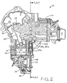
- Crankcase 12 is formed with cylinder portions 14 within each is formed a cylinder bore 16, as shown in Figure 2.
- Each cylinder bore 16 may be provided with a cylinder liner 18 along which each piston 20 reciprocatingly slides in the well known manner.
- Each piston 20 is attached via a connecting rod 22 to crankshaft 24.
- crankshaft 24 is vertically oriented and, with reference to Figure 1, extends from the top and bottom of crankcase 12.
- the present invention should not be construed as being limited to vertical shaft engines, however.
- crankshaft 26 Disposed within crankcase 12 camshaft 26 which has an axis of rotation parallel to that of crankshaft 24 and which is operably coupled thereto, as through a gear, chain or belt drive.
- Crankshaft 26 is provided with cam lobes 28a through 28d.
- cam lobes 28 includes a base or circular portion 42, and a peak 44, as described above.
- each cam lobe is slidably engaged with the foot of a lifter assembly.
- each cylinder head 30 Located over each cylinder portion 14 is a cylinder head 30 which, with the cylinder bore 16 or liner 18, and piston 20, define the combustion chamber.
- each cylinder head 30 is provided with two valves 32: one for intake to the combustion chamber, and one for exhaust from the combustion chamber, as explained above.
- Valves 32 are each biased into their closed position by means of a compression spring 34. Valves 32 are urged into their respective open positions through rocker arm assembly 36 which couples each of the valves to an associated push rod 38.
- Each push rod 38 extends between rocker arm assembly 36 and a lifter assembly 40a through 40d.
- Each of lifter assemblies 40a through 40d are identical, and lifter assembly 40d is not shown in the drawings.
- lifter assemblies 40a and 40c which respectively slidably engage cam lobes 28a and 28c, control the valves 32 in one cylinder head 30.
- Lifter assemblies 40b and 40d (the latter not shown) slidably engage cam lobes 28b and 28d, respectively, and control valves 32 in the other cylinder head 30.
- Each lifter assembly 40 includes cylindrical sleeve 46 having upper radial wall 48 and lower radial wall 50. Each sleeve 46 also has an open inward end 52 which faces cam shaft 26, and an axially opposite, open outward end 54. As best shown in Figure 4, in engine 10 each cylinder portion 14 is provided with an upper bore 56 and, located below upper bore 56, a lower bore 58; sleeves 46 are interference fitted into bores 56 and 58. Located near inward end 52 of each sleeve 46 is oil feed hole 60 located in upper radial wall 48. In the shown embodiment, oil feed hole 60 is located at the vertically uppermost portion of upper radial wall 48. Located near outward end 54 is oil bleed hole 62, also located in the vertically uppermost portion of upper radial wall 48.
- Crankcase 12 is provided with oil supply bore 64 which is supplied with pressurized lubricating oil, as from an oil pump. As shown, oil supply bore 64 extends through upper bore 56 and continues to lower bore 58. In the outer circumferential surface of sleeve 46 is provided annular oil supply groove 66 into which opens oil feed hole 60. Sleeve 46 is positioned in bores 56 and 58 such that groove 66 is in communication with oil supply bore 64. Those skilled in the art will now recognize that the pressurized oil supplied to the lifter assemblies through oil supply bore 64 will be able to reach both lifter assemblies of a given cylinder portion independently.
- each sleeve 46 Slidably disposed within each sleeve 46 is hollow cylindrical lifter body 68 which is closed at one end by a portion 70 which forms the lifter foot on the exterior of that axial end of the lifter body.
- each lifter foot is in sliding engagement with the surface of a cam lobe 28.
- the lifter foot is urged into sliding abutment with the surface of cam lobe 28 by the force of spring 34 ( Figure 2) which acts on the lifter assembly through rocker arm assembly 36 and push rod 38.
- spring 34 Figure 2 which acts on the lifter assembly through rocker arm assembly 36 and push rod 38.
- each lifter body 68 Reciprocatingly disposed within each lifter body 68 is cylindrical plunger 72 which is formed with internal cavity 74.
- the walls of cavity 74 partially define a low pressure oil reservoir 76 within the plunger 72.
- low pressure oil reservoir 76 is in at least periodic fluid communication with oil feed hole 60, whereby oil received into the oil feed hole is received into the low pressure oil reservoir 76.
- High pressure oil reservoir 78 is defined by plunger 72 and the interior of lifter body 68 near lifter body closed portion 70. Plunger 72 is provided with passage 80 over which is provided check valve 82. Low pressure oil cavity 76 is in one way fluid communication with high pressure oil reservoir 78 through passage 80 and check valve 82. The check valve allowing flow from the low pressure reservoir 76 to high pressure reservoir 78. Normally, if the pressure of oil in high pressure reservoir 78 is greater than that of low pressure reservoir 76, check valve 82 will remain closed and no oil will transfer between the two reservoirs.
- Oil received into sleeve 46 through oil feed hole 60 lubricates the interface between the inner cylindrical surface of the sleeve and the outer cylindrical surface of lifter body 68. This oil is also received in wide first circumferential groove 84 provided in the outer cylindrical surface of the lifter body.
- the inner cylindrical surface of the lifter body is provided with second circumferential groove 86 which is in fluid communication with first circumferential groove 84 through first radially directed passage 88 provided in the lifter body.
- Plunger 72 is provided with third circumferential groove 90 in its outer radial surface. Radially directed second passage 92 is located in third circumferential groove 90 and extends through the wall of the plunger to convey oil to low pressure reservoir 76 therein.
- first circumferential groove 84 is of sufficient width that regardless of the position along sleeve 46 which lifter body 68 assumes during reciprocation, oil feed hole 60 and first groove 84 are always in fluid communication with each other. Also, although second groove 86 and third groove 90 are not in superposed relation to one another, there is sufficient clearance between the slidably interfacing inner surface of valve body 68 and outer surface of plunger 72 to allow sufficient oil flow from first radial passage 88 to second radial passage 92 to feed oil to the low pressure oil reservoir.
- Socket 94 is fitted into the end of plunger 72 opposite that in which passage 80 is provided and receives hemispherical tip 96 of stem 98 extending from an axial surface of short cylindrical cap 100 which is slidably received in sleeve 46.
- Metering passage 102 is provided through socket 94 to provide oil from low pressure oil reservoir 76 to lubricate the interface between socket 94 and cap tip 96.
- Axial surface 104 of cap 100, opposite that from which stem 98 extends, is provided with cup 106 in which the end of valve push rod 38 is received.
- Compression spring 108 is provided in high pressure oil reservoir 78 and acts on lifter body closed portion 70 and the interfacing surface of plunger 72 to urge plunger 72 away from lifter body closed end 70.
- Oil in the high pressure oil reservoir 78 is allowed to leak along the interface between the inner cylindrical surface of the lifter body and the outer cylindrical surface of the plunger. Oil is prevented from leaking from the lifter assembly through the annular clearances between lifter body 68 and sleeve 46, and between cap 100 and sleeve 46, by first and second O-rings 110, 112 respectively provided in circumferential grooves 114 and 116 provided in the lifter body and the cap. Thus, oil is only allowed to exit lifter assembly 40 through bleed hole 62 in sleeve 46.
- bleed hole 62 is positioned such that it is never blocked or covered by lifter body 68 or cap 100. As noted above, each bleed hole 62 is in open fluid communication with the interior of crankcase 12.
Landscapes
- Engineering & Computer Science (AREA)
- Mechanical Engineering (AREA)
- General Engineering & Computer Science (AREA)
- Valve-Gear Or Valve Arrangements (AREA)
Abstract
A lifter assembly (40a) for an internal combustion engine (10), including an
elongate sleeve (46) having an upper radial wall portion (48) provided with oil feed (60)
and oil bleed (62) holes therethrough, through which oil respectively enters and exits the
lifter assembly. An elongate, hollow lifter body (68) is reciprocatingly disposed within
the sleeve, the lifter body being closed at one end (70) thereof. A plunger (72) is
reciprocatingly disposed within the lifter body and has an internal cavity (74), a low
pressure oil reservoir (76) at least partially defined by the plunger internal cavity, the low
pressure oil reservoir in at least periodic fluid communication with the oil feed hole,
whereby oil from the oil feed hole is received into the low pressure oil reservoir. A high
pressure oil reservoir (78) is at least partially defined by the plunger and the lifter body
closed end, and is in one-way fluid communication with the low pressure oil reservoir,
whereby oil is received into the high pressure reservoir from the low pressure oil
reservoir. A cap (100) is reciprocatingly disposed within the sleeve and engaged with the
plunger. First (110) and second (112) seals are located between an outer circumferential
surface of the lifter body and an outer circumferential surface of the cap, respectively, and
an inner circumferential surface of the sleeve, the seals respectively located between the
oil feed hole and one end (52) of the sleeve, and the oil bleed hole and the other end (54)
of the sleeve, whereby oil is precluded from exiting the lifter assembly through the ends
of the sleeve.
Description
The field of the present invention relates to hydraulic lifters or tappets for internal
combustion engines, particularly such lifters or tappets which are substantially
horizontally oriented.
Prior known engines that contain hydraulic lifter assemblies for actuating cylinder
intake and exhaust valves are well known in the art. The camshaft contains one or more
lobes which slidably engage the foot of the lifter, and force open valves which are spring-biased
into their closed positions. Gases are conducted into, or exhausted from, the
combustion chamber of the engine past the valves, which are fitted into ports provided in
a cylinder head or the cylinder block. The combustion chamber normally includes a
cylinder, over which the cylinder head is disposed, and in which a piston reciprocates; the
piston is operably coupled to a rotatable crankshaft, which has an axis of rotation
normally parallel with that of the camshaft. In the well known manner, combustion
within the chamber forces the piston away from the head, driving the crankshaft. In a
single cylinder engine, angular inertia of the crankshaft causes the reciprocating piston to
approach the head. In multiple cylinder engines, the reciprocating piston is also urged
toward the head under power of the crankshaft as pistons in other cylinders are similarly
urged away from their respective heads during combustion therein.
The camshaft is driven by the crankshaft, and may be operably coupled by means
of a gear drive, a belt drive or a chain drive, all of which are well known in the art and
provide the proper camshaft/crankshaft drive ratio. In a four stroke engine, the crankshaft
rotates twice for each rotation of the camshaft, and each piston successively undergoes
compression, power, exhaust and intake strokes in each cycle. Ignition of a fuel/air
mixture within the combustion chamber, which causes combustion therein, occurs at or
near the beginning of the power stroke. During the compression and power strokes, the
exhaust and intake valves are normally closed. During the exhaust stroke or intake stroke,
the respective exhaust valve or intake valve is open, and gas respectively exits or enters
the cylinder past the valve. The timing and duration of the valve openings and closings,
as well as the distance by which the valve is opened, is controlled by the profile of the
cam lobes.
In two stroke engines, each piston successively undergoes compression/exhaust
and power/intake strokes in each cycle. During a portion of the compression stroke, the
exhaust valve is open; during a portion of the power stroke, the suction valve is open.
Thus, for each rotation of the camshaft, in a two stroke engine the crankshaft rotates once
As noted above, the foot of each lifter rides on a cam lobe. As the lifter foot
follows the profile of the cam lobe, the spring-biased valve is forced off of its seat, which
surrounds the respective port, to open the valve, and is allowed to return to its seat to
close the valve. The valves and the camshaft lobes are thus operably engaged through the
lifters, as well as through any intervening valve rods or rocker arm assemblies which are
also included in the valve train to manipulate the direction of motion and/or
proportionally change the amount of lift imparted to the valve, as known in the art.
Lifters or tappets are generally of two types: Solid and hydraulic. Solid lifters are
comparatively cheaper, include fewer components, and offer a somewhat greater degree of
control over valve travel because they do not compress. Solid lifters, however, require
periodic adjustment to maintain proper valve train operating tolerances. When out of
tolerance, solid lifters are prone to cause undesirable noise during engine operation as the
lifter foot and cam lobes, or other parts of the valve train, slightly separate and
subsequently strike each other.
Hydraulic lifters are comparatively more expensive than solid lifters and include
more component parts. Nevertheless, they are virtually maintenance-free and normally
very quiet. Further, in most engines, hydraulic lifters offer a satisfactory degree of control
over valve travel, despite their being compressible.
The hydraulic lifter assembly may comprise an elongate, usually cylindrical body,
closed on one end by the portion forming the foot of the lifter. The lifter body is normally
slidably disposed in a bore provided in the cylinder block or valve head which extends
perpendicularly relative to the axis of rotation of the camshaft. The foot of each lifter
body rides on the profile of a different cam lobe as the lifter body reciprocates within its
bore.
A hollow plunger, also usually cylindrical, is slidably disposed within the lifter
body, and is spring-biased away from the foot. The end of the plunger opposite the foot
of the lifter body engages its valve, perhaps, as mentioned above, through valve rods
and/or rocker arms. The plunger contains a low pressure reservoir into which engine oil is
received. The lifter body has a high pressure oil, expansible reservoir located between the
foot and the plunger. The high pressure reservoir is in one-way fluid communication
with, and receives oil from, the low pressure reservoir through a check valve.
During operation, as the highest part or peak of the rotating cam lobe moves out
from under the foot of the lifter body, and the lifter body consequently advances radially
toward the axis of rotation of the camshaft, the spring within the lifter assembly forces the
foot away from the plunger, and oil from the low pressure reservoir is drawn through the
check valve into the high pressure reservoir, thereby fully charging the high pressure
reservoir with oil as the lifter foot encounters the base or circular portion of the cam lobe.
As the lifter foot encounters the ramp portion of the cam lobe which extends from the
base to the peak, the lifter body is forced radially away from the axis of rotation of the
camshaft. The lifter assembly spring and the oil in the high pressure reservoir is
compressed, and the plunger forces the valve open. The compressed oil in the high
pressure reservoir is forced therefrom through clearances between the valve body and the
plunger, and subsequently from between the valve body and the bore in which it
reciprocates. Thus, a hydraulic lifter forms a dashpot.
As the reciprocating lifter body again advances towards the axis of rotation of the
camshaft, oil is again drawn from the low pressure reservoir to the high pressure reservoir
as the lifter assembly spring forces the lifter body and plunger axially apart, and the cycle
continues.
To ensure quiet and reliable operation of the lifter assembly, it is important that an
adequate supply of oil be provided to both the low and high pressure reservoirs at all
times. A problem often encountered is that, during engine shutdown periods, oil will leak
or drain from the reservoirs of the lifter assemblies. This leakdown phenomena is
particularly common in engines which have horizontally-oriented lifter assemblies.
Vertically-oriented lifter assemblies do not experience this problem to the same degree as
horizontally-oriented lifter assemblies do, because the lifter bodies of most vertically-oriented
lifter assemblies are closed by foot-forming lower portions and therefore have a
tendency to retain oil therein.
Upon subsequent startup of engines having previous horizontally-oriented lifter
assemblies, at least the high pressure reservoirs, and perhaps also the low pressure
reservoirs, of the lifter assemblies may be depleted of oil and largely contain air.
Consequently, these lifter assemblies compress too readily and too far, resulting in
undesirable noise or improper valve timing, at least temporarily, as well as possible
damage to components of the valve train (including the lifter assemblies themselves).
Thus, a hydraulic lifter assembly which precludes oil from leaking therefrom, and air from
entering thereinto, during engine shutdown periods is highly desirable.
The present invention addresses the above-mentioned leakdown problem by
providing a hydraulic lifter assembly which allows no oil to leak out of its reservoirs
during engine shutdown periods.
The present invention provides a lifter assembly for an internal combustion
engine, including an elongate sleeve having an upper radial wall portion provided with oil
feed and oil bleed holes therethrough, through which oil respectively enters and exits the
lifter assembly. An elongate, hollow lifter body is reciprocatingly disposed within the
sleeve, the lifter body being closed at one end thereof. A plunger is reciprocatingly
disposed within the lifter body and has an internal cavity, a low pressure oil reservoir at
least partially defined by the plunger internal cavity, the low pressure oil reservoir in at
least periodic fluid communication with the oil feed hole, whereby oil from the oil feed
hole is received into the low pressure oil reservoir. A high pressure oil reservoir is at least
partially defined by the plunger and the lifter body closed end, and is in one-way fluid
communication with the low pressure oil reservoir, whereby oil is received into the high
pressure reservoir from the low pressure oil reservoir. A cap is reciprocatingly disposed
within the sleeve and engaged with the plunger. First and second seals are located
between an outer circumferential surface of the lifter body and an outer circumferential
surface of the cap, respectively, and an inner circumferential surface of the sleeve, the
seals respectively located between the oil feed hole and one end of the sleeve, and the oil
bleed hole and the other end of the sleeve, whereby oil is precluded from exiting the lifter
assembly through the ends of the sleeve.
The present invention also provides an arrangement of first and second lifter
assemblies, wherein each of the first and second lifter assemblies includes a sleeve in
which a lifter body reciprocates, each sleeve provided with an oil feed hole through which
oil is provided to the lifter body therein. The oil feed holes of the first and second lifter
assemblies are in parallel fluid communication with a source of oil which includes a first
oil conduit. A circumferential groove is located about the first lifter assembly sleeve, the
oil feed hole of the first lifter assembly sleeve opening into the circumferential groove,
and a second conduit is provided through which the circumferential groove and the
second lifter assembly oil feed hole are placed in fluid communication.
The above-mentioned and other features and advantages of this invention, and the
manner of attaining them, will become more apparent and the invention itself will be
better understood by reference to the following description of an embodiment of the
invention taken in conjunction with the accompanying drawings, wherein:
Corresponding reference characters indicate corresponding parts throughout the
several views. The exemplification set out herein illustrates one embodiment of the
present invention, and such exemplification is not to be construed as limiting the scope of
the invention in any manner.
Figure 1 shows engine 10 which is of the four stroke, V-twin cylinder variety
having crankcase 12. Crankcase 12 is formed with cylinder portions 14 within each is
formed a cylinder bore 16, as shown in Figure 2. Each cylinder bore 16 may be provided
with a cylinder liner 18 along which each piston 20 reciprocatingly slides in the well
known manner. Each piston 20 is attached via a connecting rod 22 to crankshaft 24. In
engine 10, crankshaft 24 is vertically oriented and, with reference to Figure 1, extends
from the top and bottom of crankcase 12. The present invention should not be construed
as being limited to vertical shaft engines, however.
Disposed within crankcase 12 camshaft 26 which has an axis of rotation parallel to
that of crankshaft 24 and which is operably coupled thereto, as through a gear, chain or
belt drive. Crankshaft 26 is provided with cam lobes 28a through 28d. Referring to
Figure 2 it can be seen that each of cam lobes 28 includes a base or circular portion 42,
and a peak 44, as described above. As will be discussed further herein below, each cam
lobe is slidably engaged with the foot of a lifter assembly.
Located over each cylinder portion 14 is a cylinder head 30 which, with the
cylinder bore 16 or liner 18, and piston 20, define the combustion chamber. In engine 10,
each cylinder head 30 is provided with two valves 32: one for intake to the combustion
chamber, and one for exhaust from the combustion chamber, as explained above. Valves
32 are each biased into their closed position by means of a compression spring 34. Valves
32 are urged into their respective open positions through rocker arm assembly 36 which
couples each of the valves to an associated push rod 38. Each push rod 38 extends
between rocker arm assembly 36 and a lifter assembly 40a through 40d. Each of lifter
assemblies 40a through 40d are identical, and lifter assembly 40d is not shown in the
drawings.
As can be seen from Figures 2 and 3, lifter assemblies 40a and 40c, which
respectively slidably engage cam lobes 28a and 28c, control the valves 32 in one cylinder
head 30. Lifter assemblies 40b and 40d (the latter not shown) slidably engage cam lobes
28b and 28d, respectively, and control valves 32 in the other cylinder head 30.
Each lifter assembly 40 includes cylindrical sleeve 46 having upper radial wall 48
and lower radial wall 50. Each sleeve 46 also has an open inward end 52 which faces cam
shaft 26, and an axially opposite, open outward end 54. As best shown in Figure 4, in
engine 10 each cylinder portion 14 is provided with an upper bore 56 and, located below
upper bore 56, a lower bore 58; sleeves 46 are interference fitted into bores 56 and 58.
Located near inward end 52 of each sleeve 46 is oil feed hole 60 located in upper radial
wall 48. In the shown embodiment, oil feed hole 60 is located at the vertically uppermost
portion of upper radial wall 48. Located near outward end 54 is oil bleed hole 62, also
located in the vertically uppermost portion of upper radial wall 48.
Slidably disposed within each sleeve 46 is hollow cylindrical lifter body 68 which
is closed at one end by a portion 70 which forms the lifter foot on the exterior of that axial
end of the lifter body. As best shown in Figure 3, each lifter foot is in sliding engagement
with the surface of a cam lobe 28. In the usual manner, the lifter foot is urged into sliding
abutment with the surface of cam lobe 28 by the force of spring 34 (Figure 2) which acts
on the lifter assembly through rocker arm assembly 36 and push rod 38. As cam shaft 26
rotates, lifter body 68 reciprocates within its respective sleeve 46.
Reciprocatingly disposed within each lifter body 68 is cylindrical plunger 72
which is formed with internal cavity 74. The walls of cavity 74 partially define a low
pressure oil reservoir 76 within the plunger 72. As will be described further herein below,
low pressure oil reservoir 76 is in at least periodic fluid communication with oil feed hole
60, whereby oil received into the oil feed hole is received into the low pressure oil
reservoir 76.
High pressure oil reservoir 78 is defined by plunger 72 and the interior of lifter
body 68 near lifter body closed portion 70. Plunger 72 is provided with passage 80 over
which is provided check valve 82. Low pressure oil cavity 76 is in one way fluid
communication with high pressure oil reservoir 78 through passage 80 and check valve
82. The check valve allowing flow from the low pressure reservoir 76 to high pressure
reservoir 78. Normally, if the pressure of oil in high pressure reservoir 78 is greater than
that of low pressure reservoir 76, check valve 82 will remain closed and no oil will
transfer between the two reservoirs.
Oil received into sleeve 46 through oil feed hole 60 lubricates the interface
between the inner cylindrical surface of the sleeve and the outer cylindrical surface of
lifter body 68. This oil is also received in wide first circumferential groove 84 provided
in the outer cylindrical surface of the lifter body. The inner cylindrical surface of the lifter
body is provided with second circumferential groove 86 which is in fluid communication
with first circumferential groove 84 through first radially directed passage 88 provided in
the lifter body. Plunger 72 is provided with third circumferential groove 90 in its outer
radial surface. Radially directed second passage 92 is located in third circumferential
groove 90 and extends through the wall of the plunger to convey oil to low pressure
reservoir 76 therein.
As best shown in Figure 5, first circumferential groove 84 is of sufficient width
that regardless of the position along sleeve 46 which lifter body 68 assumes during
reciprocation, oil feed hole 60 and first groove 84 are always in fluid communication with
each other. Also, although second groove 86 and third groove 90 are not in superposed
relation to one another, there is sufficient clearance between the slidably interfacing inner
surface of valve body 68 and outer surface of plunger 72 to allow sufficient oil flow from
first radial passage 88 to second radial passage 92 to feed oil to the low pressure oil
reservoir.
While the present invention has been described as having an exemplary design, the
present invention can be further modified within the spirit and scope of this disclosure.
This application is therefore intended to cover any variations, uses, or adaptations of the
invention using its general principles. For example, the scope of the present invention
encompasses lifter assemblies for two stroke spark ignition engines and compression
ignition (i.e., diesel) engines, as well as for four stroke spark ignition engines such as
engine 10. Further, this application is intended to cover such departures from the present
disclosure as come within known or customary practice in the art to which this invention
pertains.
Claims (26)
- A lifter assembly (40a) for an internal combustion engine (10), including an elongate sleeve (46) having an upper radial wall portion (48), said upper radial wall portion being provided with an oil feed hole (60) through which oil enters said lifter assembly, and an oil bleed hole (62) through which oil exits said lifter assembly, said oil feed hole and said oil bleed hole extending through said upper radial wall portion, an elongate lifter body (68) reciprocatingly disposed within said sleeve, said lifter body being hollow and closed at one end (70) thereof, a plunger (72) reciprocatingly disposed within said lifter body, said plunger having an internal cavity (74), a low pressure oil reservoir (76) at least partially defined by said plunger internal cavity, said low pressure oil reservoir in at least periodic fluid communication with said oil feed hole, whereby oil from said oil feed hole is received into said low pressure oil reservoir, and a high pressure oil reservoir (78) at least partially defined by said plunger and said lifter body closed end, said low pressure oil reservoir and said high pressure oil reservoir in one-way fluid communication, whereby oil is received into said high pressure reservoir from said low pressure oil reservoir; characterized by a cap (100) reciprocatingly disposed within said sleeve, said cap being engaged with said plunger, a first seal (110) located between an outer circumferential surface of said lifter body and an inner circumferential surface of said sleeve, said first seal located between said oil feed hole and one end (52) of said sleeve, and a second seal (112) located between an outer circumferential surface of said cap and said sleeve inner circumferential surface, said second seal located between said oil bleed hole and the other end (54) of said sleeve, whereby oil is precluded from exiting said lifter assembly through the ends of said sleeve.
- The lifter assembly of claim 1, characterized in that said lifter body reciprocates in substantially horizontal directions.
- The lifter assembly of claim 1, characterized in that said oil feed hole and said oil bleed hole are spaced along the length of said sleeve.
- The lifter assembly of claim 1, characterized in that said high pressure oil reservoir is in restricted fluid communication with said oil bleed hole, whereby oil from said high pressure oil reservoir is received, at a lower pressure, into said oil bleed hole.
- The lifter assembly of claim 4, characterized in that an inner surface of said lifter body and an outer surface of said plunger interface and form a clearance therebetween, said high pressure oil reservoir in fluid communication with said oil bleed hole through said clearance.
- The lifter assembly of claim 1, characterized in that said sleeve, said lifter body and said plunger are cylindrical, and said cap has a cylindrical portion on which said cap outer circumferential surface is located.
- The lifter assembly of claim 6, characterized in that said lifter body outer circumferential surface and said cap cylindrical portion outer circumferential surface are each provided with circumferential grooves (114, 116) in which said first and second seals are respectively disposed.
- The lifter assembly of claim 1, characterized by a passage (80) extending between said low pressure oil reservoir and said high pressure oil reservoir, and a check valve (82) disposed over said passage, whereby oil may flow in only one direction through said passage.
- The lifter assembly of claim 8, characterized in that oil flow through said passage is from said low pressure oil reservoir to said high pressure oil reservoir.
- The lifter assembly of claim 1, characterized in that said plunger is biased away from said lifter body closed end.
- The lifter assembly of claim 10, characterized by a compression spring (108) disposed in said high pressure oil reservoir, said spring abutting said lifter body closed end and said plunger, whereby said plunger is biased away from said lifter body closed end.
- The lifter assembly of claim 1, characterized by said cap having a tip (96) and by a socket (94) disposed between said plunger and said cap, said socket partially defining said low pressure oil reservoir and having a recess into which said cap tip is received.
- The lifter assembly of claim 12, characterized in that said socket includes a metering passage (102) extending between said low pressure oil reservoir and said recess, the interface between said socket and said cap tip being provided with oil through said metering passage.
- The lifter assembly of claim 1, characterized in that said oil feed hole and said oil bleed hole are each located at the uppermost portion of said sleeve upper radial wall portion.
- The lifter assembly of claim 1, characterized in that said lifter body has an outer circumferential surface in which a first circumferential groove (84) is located, said first circumferential groove at all times open to said sleeve oil feed hole, said lifter body having an inner circumferential surface in which a second circumferential groove (86) is located, said first and second circumferential grooves in fluid communication through a first passage (88) extending through said lifter body, said plunger has an outer circumferential surface in which a third circumferential groove (90) is located, said third circumferential groove and said low pressure oil reservoir in fluid communication through a second passage (92) extending through said plunger, and said second and third circumferential grooves are in at least periodic fluid communication.
- The lifter assembly of claim 1, characterized in that said lifter body closed end forms a lifter foot.
- The lifter assembly of claim 1, characterized in that an oil chamber is formed between said cap and said lifter body, said oil bleed hole at all times open to said oil chamber, and oil from said high pressure oil reservoir is received in said oil chamber.
- In combination with the lifter assembly of claim 1, a second said lifter assembly (40c), said oil feed holes of said first and second lifter assemblies in parallel fluid communication with a source of oil.
- The combination of claim 18, characterized in that said source of oil includes a first oil conduit (64), and the sleeve of said first lifter assembly has an outer circumferential surface in which a circumferential groove (66) is located, said first lifter assembly oil feed hole located in said circumferential groove, said first oil conduit opening into said first lifter assembly circumferential groove, and said first oil conduit is in fluid communication with the oil feed hole of said second lifter assembly through a second conduit (64), said second conduit extending between said second lifter assembly and said circumferential groove of said first lifter assembly.
- The combination of claim 19, characterized in that said first and second oil conduits are axially aligned.
- The combination of claim 19, characterized in that said first oil conduit approaches said first lifter assembly from above said first lifter assembly.
- The combination of claim 21, characterized in that said first lifter assembly is located above said second lifter assembly.
- An arrangement of first (40a) and second (40c) lifter assemblies, each of said first and second lifter assemblies having a sleeve (46) in which a lifter body (68) reciprocates, each said sleeve provided with an oil feed hole (60) through which oil is provided to the lifter body therein; characterized in that the oil feed holes of said first and second lifter assemblies are in parallel fluid communication with a source of oil which includes a first oil conduit (64), a circumferential groove (66) is located about said first lifter assembly sleeve, said oil feed hole of said first lifter assembly sleeve opening into said circumferential groove, and a second conduit (64) is provided through which said circumferential groove and said second lifter assembly oil feed hole are placed in fluid communication.
- The lifter assembly arrangement of claim 23, characterized in that said first and second conduits are axially aligned.
- The lifter assembly arrangement of claim 24, characterized in that said first lifter assembly is located above said second lifter assembly.
- The lifter assembly arrangement of claim 24, characterized in that said first conduit approaches said first lifter from above.
Applications Claiming Priority (2)
| Application Number | Priority Date | Filing Date | Title |
|---|---|---|---|
| US09/761,353 US6460499B1 (en) | 2001-01-16 | 2001-01-16 | Hydraulic lifter assembly |
| US761353 | 2001-01-16 |
Publications (1)
| Publication Number | Publication Date |
|---|---|
| EP1223310A1 true EP1223310A1 (en) | 2002-07-17 |
Family
ID=25061952
Family Applications (1)
| Application Number | Title | Priority Date | Filing Date |
|---|---|---|---|
| EP02000684A Withdrawn EP1223310A1 (en) | 2001-01-16 | 2002-01-11 | Hydraulic lifter assembly |
Country Status (3)
| Country | Link |
|---|---|
| US (1) | US6460499B1 (en) |
| EP (1) | EP1223310A1 (en) |
| CA (1) | CA2367555C (en) |
Cited By (2)
| Publication number | Priority date | Publication date | Assignee | Title |
|---|---|---|---|---|
| EP3526450A4 (en) * | 2016-10-17 | 2020-05-20 | Eaton Intelligent Power Limited | HYDRAULIC GAME RETRACTOR ASSEMBLY SLEEVES |
| EP3581770A4 (en) * | 2017-02-10 | 2020-10-28 | OTICS Corporation | PISTON |
Families Citing this family (12)
| Publication number | Priority date | Publication date | Assignee | Title |
|---|---|---|---|---|
| US7263956B2 (en) | 1999-07-01 | 2007-09-04 | Delphi Technologies, Inc. | Valve lifter assembly for selectively deactivating a cylinder |
| DE10146129A1 (en) | 2001-09-19 | 2003-04-03 | Ina Schaeffler Kg | Switching element for a valve train of an internal combustion engine |
| EP1472438B1 (en) | 2002-02-06 | 2005-07-27 | INA-Schaeffler KG | Switch element for valve actuation in an internal combustion engine |
| US6802288B2 (en) * | 2002-04-22 | 2004-10-12 | Delphi Technologies, Inc. | Deactivation hydraulic valve lifter having a pressurized oil groove |
| US7055471B2 (en) * | 2002-05-28 | 2006-06-06 | Kohler Co. | Hydraulic lifter feed gallery with aeration removal orifice |
| US7464678B2 (en) * | 2007-02-15 | 2008-12-16 | Gm Global Technology Operations, Inc. | Hydraulic lash adjuster |
| US8161929B2 (en) | 2007-11-21 | 2012-04-24 | Schaeffler Kg | Switchable tappet |
| US8357206B2 (en) * | 2008-03-06 | 2013-01-22 | Alps Intellectual Property Management, Llc | Prosthetic liner with proximal seal |
| US8196556B2 (en) * | 2009-09-17 | 2012-06-12 | Delphi Technologies, Inc. | Apparatus and method for setting mechanical lash in a valve-deactivating hydraulic lash adjuster |
| DE102010018208A1 (en) * | 2010-04-26 | 2011-10-27 | Schaeffler Technologies Gmbh & Co. Kg | Hydraulic valve clearance compensation element for reciprocating internal combustion engines |
| KR101428378B1 (en) * | 2013-04-05 | 2014-08-07 | 현대자동차주식회사 | Lubrication apparatus of high pressure pump for common rail system |
| WO2021055191A1 (en) * | 2019-09-20 | 2021-03-25 | Cummins Inc. | Mechanically timed cylinder deactivation system |
Citations (5)
| Publication number | Priority date | Publication date | Assignee | Title |
|---|---|---|---|---|
| GB185893A (en) * | 1921-07-06 | 1922-09-21 | Geoffrey Hamilton Norman | Improvements in tappet gear for internal combustion engines and the like |
| US3299870A (en) * | 1965-02-06 | 1967-01-24 | Bosch Gmbh Robert | Valve-operating mechanism for internal combustion engines |
| US3650251A (en) * | 1970-05-11 | 1972-03-21 | Mack Trucks | Hydraulic valve lifter |
| US4601267A (en) * | 1985-07-26 | 1986-07-22 | Tecumseh Products Company | Valve mechanism lubrication system for an overhead valve engine |
| US4924821A (en) * | 1988-12-22 | 1990-05-15 | General Motors Corporation | Hydraulic lash adjuster and bridge assembly |
Family Cites Families (13)
| Publication number | Priority date | Publication date | Assignee | Title |
|---|---|---|---|---|
| US2539877A (en) | 1945-06-27 | 1951-01-30 | Eaton Mfg Co | Hydraulic tappet |
| US2954015A (en) | 1958-10-23 | 1960-09-27 | Eaton Mfg Co | Lubricant delivery control |
| US2938508A (en) | 1959-06-04 | 1960-05-31 | Gen Motors Corp | Horizontally operable hydraulic valve lifter |
| US2962012A (en) | 1959-12-28 | 1960-11-29 | Gen Motors Corp | Horizontally operable hydraulic valve lifter |
| US3070080A (en) | 1961-06-30 | 1962-12-25 | Gen Motors Corp | Horizontal valve lifter |
| US3053239A (en) | 1961-06-30 | 1962-09-11 | Gen Motors Corp | Horizontal hydraulic valve lifter |
| US3139078A (en) | 1962-06-20 | 1964-06-30 | Gen Motors Corp | Horizontal hydraulic valve lifter |
| US3262434A (en) | 1963-03-02 | 1966-07-26 | Motomak Motorenbau Maschinenun | Self-adjusting hydraulic valve lifter for piston engines |
| US4184464A (en) | 1977-05-13 | 1980-01-22 | Stanadyne, Inc. | Recirculation groove for hydraulic lash adjuster |
| DE2843918C2 (en) | 1978-10-09 | 1980-12-18 | Ford-Werke Ag, 5000 Koeln | Hydraulic tappet for a valve train of an internal combustion engine |
| JPS582405A (en) | 1981-06-26 | 1983-01-08 | Fuji Heavy Ind Ltd | Oil evacuation preventive device of rush adjuster |
| JPS59105005U (en) | 1982-12-29 | 1984-07-14 | アイシン精機株式会社 | hydraulic lifter |
| JPS59200006A (en) * | 1983-04-28 | 1984-11-13 | Yanmar Diesel Engine Co Ltd | Pump style hydraulic tappet valve of internal combustion engine |
-
2001
- 2001-01-16 US US09/761,353 patent/US6460499B1/en not_active Expired - Fee Related
-
2002
- 2002-01-11 EP EP02000684A patent/EP1223310A1/en not_active Withdrawn
- 2002-01-14 CA CA002367555A patent/CA2367555C/en not_active Expired - Lifetime
Patent Citations (5)
| Publication number | Priority date | Publication date | Assignee | Title |
|---|---|---|---|---|
| GB185893A (en) * | 1921-07-06 | 1922-09-21 | Geoffrey Hamilton Norman | Improvements in tappet gear for internal combustion engines and the like |
| US3299870A (en) * | 1965-02-06 | 1967-01-24 | Bosch Gmbh Robert | Valve-operating mechanism for internal combustion engines |
| US3650251A (en) * | 1970-05-11 | 1972-03-21 | Mack Trucks | Hydraulic valve lifter |
| US4601267A (en) * | 1985-07-26 | 1986-07-22 | Tecumseh Products Company | Valve mechanism lubrication system for an overhead valve engine |
| US4924821A (en) * | 1988-12-22 | 1990-05-15 | General Motors Corporation | Hydraulic lash adjuster and bridge assembly |
Cited By (2)
| Publication number | Priority date | Publication date | Assignee | Title |
|---|---|---|---|---|
| EP3526450A4 (en) * | 2016-10-17 | 2020-05-20 | Eaton Intelligent Power Limited | HYDRAULIC GAME RETRACTOR ASSEMBLY SLEEVES |
| EP3581770A4 (en) * | 2017-02-10 | 2020-10-28 | OTICS Corporation | PISTON |
Also Published As
| Publication number | Publication date |
|---|---|
| CA2367555A1 (en) | 2002-07-16 |
| US6460499B1 (en) | 2002-10-08 |
| CA2367555C (en) | 2006-03-14 |
| US20020162525A1 (en) | 2002-11-07 |
Similar Documents
| Publication | Publication Date | Title |
|---|---|---|
| CA2367555C (en) | Hydraulic lifter assembly | |
| EP0003439B1 (en) | Internal combustion engine | |
| US5127375A (en) | Hydraulic valve control system for internal combustion engines | |
| JP2778930B2 (en) | Two-stage valve lifter | |
| US7509933B2 (en) | Valve lash adjuster having electro-hydraulic lost-motion capability | |
| US3742921A (en) | Variable lift hydraulic valve lifter | |
| US3509858A (en) | Overhead cam valve lifter | |
| KR930007445B1 (en) | Hydraulic lash adjuster & bridge assembly | |
| US3658038A (en) | Tappet for overhead camshaft engine | |
| US4941438A (en) | Hydraulic valve-lash adjuster | |
| US6920857B2 (en) | Deactivation hydraulic valve lifter having a pressurized oil groove | |
| EP2538043A1 (en) | Hydraulic lash adjuster including band of radial recirculation openings | |
| JP6394413B2 (en) | Lubricating device for internal combustion engine | |
| KR100299302B1 (en) | Valve control means | |
| US9523291B2 (en) | Valve actuation system having rocker-located hydraulic reservoir | |
| US4020806A (en) | Hydraulic valve lifter for internal combustion engine | |
| JPH0225010B2 (en) | ||
| EP1243763A2 (en) | Internal-combustion engine with hydraulic system for variable operation of the valves and with means for bleeding the hydraulic system | |
| US7228832B2 (en) | Internal combustion engine with translatable camshaft | |
| US5709181A (en) | Rocker arm assembly | |
| KR100230054B1 (en) | Hydraulic valve lifter | |
| US4612883A (en) | Hydraulically actuated valve train for an internal combustion engine | |
| EP0028736A1 (en) | Hydraulic tappet | |
| US4677945A (en) | Mechanical valve lifter construction adapted for mechanical/hydraulic valve lifter interchangability | |
| JPS584165B2 (en) | Piston reciprocating internal combustion engine |
Legal Events
| Date | Code | Title | Description |
|---|---|---|---|
| PUAI | Public reference made under article 153(3) epc to a published international application that has entered the european phase |
Free format text: ORIGINAL CODE: 0009012 |
|
| AK | Designated contracting states |
Kind code of ref document: A1 Designated state(s): AT BE CH CY DE DK ES FI FR GB GR IE IT LI LU MC NL PT SE TR |
|
| AX | Request for extension of the european patent |
Free format text: AL;LT;LV;MK;RO;SI |
|
| 17P | Request for examination filed |
Effective date: 20021114 |
|
| 17Q | First examination report despatched |
Effective date: 20030210 |
|
| AKX | Designation fees paid |
Designated state(s): DE FR GB IT SE |
|
| STAA | Information on the status of an ep patent application or granted ep patent |
Free format text: STATUS: THE APPLICATION HAS BEEN WITHDRAWN |
|
| 18W | Application withdrawn |
Effective date: 20040127 |