EP3526408B1 - Material transfer vehicle - Google Patents
Material transfer vehicle Download PDFInfo
- Publication number
- EP3526408B1 EP3526408B1 EP17859421.4A EP17859421A EP3526408B1 EP 3526408 B1 EP3526408 B1 EP 3526408B1 EP 17859421 A EP17859421 A EP 17859421A EP 3526408 B1 EP3526408 B1 EP 3526408B1
- Authority
- EP
- European Patent Office
- Prior art keywords
- conveyor
- truck
- material transfer
- transfer vehicle
- upper side
- Prior art date
- Legal status (The legal status is an assumption and is not a legal conclusion. Google has not performed a legal analysis and makes no representation as to the accuracy of the status listed.)
- Active
Links
Images



Classifications
-
- B—PERFORMING OPERATIONS; TRANSPORTING
- B60—VEHICLES IN GENERAL
- B60R—VEHICLES, VEHICLE FITTINGS, OR VEHICLE PARTS, NOT OTHERWISE PROVIDED FOR
- B60R3/00—Arrangements of steps or ladders facilitating access to or on the vehicle, e.g. running-boards
- B60R3/02—Retractable steps or ladders, e.g. movable under shock
-
- B—PERFORMING OPERATIONS; TRANSPORTING
- B60—VEHICLES IN GENERAL
- B60R—VEHICLES, VEHICLE FITTINGS, OR VEHICLE PARTS, NOT OTHERWISE PROVIDED FOR
- B60R21/00—Arrangements or fittings on vehicles for protecting or preventing injuries to occupants or pedestrians in case of accidents or other traffic risks
- B60R21/02—Occupant safety arrangements or fittings, e.g. crash pads
- B60R21/12—Occupant safety arrangements or fittings, e.g. crash pads which protect the occupants against personal attack from the inside or the outside of the vehicle
-
- B—PERFORMING OPERATIONS; TRANSPORTING
- B60—VEHICLES IN GENERAL
- B60R—VEHICLES, VEHICLE FITTINGS, OR VEHICLE PARTS, NOT OTHERWISE PROVIDED FOR
- B60R3/00—Arrangements of steps or ladders facilitating access to or on the vehicle, e.g. running-boards
- B60R3/005—Catwalks, running boards for vehicle tops, access means for vehicle tops; Handrails therefor
-
- B—PERFORMING OPERATIONS; TRANSPORTING
- B65—CONVEYING; PACKING; STORING; HANDLING THIN OR FILAMENTARY MATERIAL
- B65G—TRANSPORT OR STORAGE DEVICES, e.g. CONVEYORS FOR LOADING OR TIPPING, SHOP CONVEYOR SYSTEMS OR PNEUMATIC TUBE CONVEYORS
- B65G21/00—Supporting or protective framework or housings for endless load-carriers or traction elements of belt or chain conveyors
- B65G21/10—Supporting or protective framework or housings for endless load-carriers or traction elements of belt or chain conveyors movable, or having interchangeable or relatively movable parts; Devices for moving framework or parts thereof
- B65G21/12—Supporting or protective framework or housings for endless load-carriers or traction elements of belt or chain conveyors movable, or having interchangeable or relatively movable parts; Devices for moving framework or parts thereof to allow adjustment of position of load-carrier or traction element as a whole
-
- B—PERFORMING OPERATIONS; TRANSPORTING
- B65—CONVEYING; PACKING; STORING; HANDLING THIN OR FILAMENTARY MATERIAL
- B65G—TRANSPORT OR STORAGE DEVICES, e.g. CONVEYORS FOR LOADING OR TIPPING, SHOP CONVEYOR SYSTEMS OR PNEUMATIC TUBE CONVEYORS
- B65G41/00—Supporting frames or bases for conveyors as a whole, e.g. transportable conveyor frames
- B65G41/001—Supporting frames or bases for conveyors as a whole, e.g. transportable conveyor frames with the conveyor adjustably mounted on the supporting frame or base
- B65G41/002—Pivotably mounted
-
- B—PERFORMING OPERATIONS; TRANSPORTING
- B65—CONVEYING; PACKING; STORING; HANDLING THIN OR FILAMENTARY MATERIAL
- B65G—TRANSPORT OR STORAGE DEVICES, e.g. CONVEYORS FOR LOADING OR TIPPING, SHOP CONVEYOR SYSTEMS OR PNEUMATIC TUBE CONVEYORS
- B65G41/00—Supporting frames or bases for conveyors as a whole, e.g. transportable conveyor frames
- B65G41/007—Means for moving conveyor frames and control arrangements therefor
- B65G41/008—Means for moving conveyor frames and control arrangements therefor frames mounted on wheels or caterpillar
-
- E—FIXED CONSTRUCTIONS
- E01—CONSTRUCTION OF ROADS, RAILWAYS, OR BRIDGES
- E01C—CONSTRUCTION OF, OR SURFACES FOR, ROADS, SPORTS GROUNDS, OR THE LIKE; MACHINES OR AUXILIARY TOOLS FOR CONSTRUCTION OR REPAIR
- E01C19/00—Machines, tools or auxiliary devices for preparing or distributing paving materials, for working the placed materials, or for forming, consolidating, or finishing the paving
- E01C19/02—Machines, tools or auxiliary devices for preparing or distributing paving materials, for working the placed materials, or for forming, consolidating, or finishing the paving for preparing the materials
- E01C19/08—Apparatus for transporting and heating or melting asphalt, bitumen, tar, or the like
-
- E—FIXED CONSTRUCTIONS
- E01—CONSTRUCTION OF ROADS, RAILWAYS, OR BRIDGES
- E01C—CONSTRUCTION OF, OR SURFACES FOR, ROADS, SPORTS GROUNDS, OR THE LIKE; MACHINES OR AUXILIARY TOOLS FOR CONSTRUCTION OR REPAIR
- E01C19/00—Machines, tools or auxiliary devices for preparing or distributing paving materials, for working the placed materials, or for forming, consolidating, or finishing the paving
- E01C19/48—Machines, tools or auxiliary devices for preparing or distributing paving materials, for working the placed materials, or for forming, consolidating, or finishing the paving for laying-down the materials and consolidating them, or finishing the surface, e.g. slip forms therefor, forming kerbs or gutters in a continuous operation in situ
-
- B—PERFORMING OPERATIONS; TRANSPORTING
- B65—CONVEYING; PACKING; STORING; HANDLING THIN OR FILAMENTARY MATERIAL
- B65G—TRANSPORT OR STORAGE DEVICES, e.g. CONVEYORS FOR LOADING OR TIPPING, SHOP CONVEYOR SYSTEMS OR PNEUMATIC TUBE CONVEYORS
- B65G2207/00—Indexing codes relating to constructional details, configuration and additional features of a handling device, e.g. Conveyors
- B65G2207/40—Safety features of loads, equipment or persons
-
- E—FIXED CONSTRUCTIONS
- E01—CONSTRUCTION OF ROADS, RAILWAYS, OR BRIDGES
- E01C—CONSTRUCTION OF, OR SURFACES FOR, ROADS, SPORTS GROUNDS, OR THE LIKE; MACHINES OR AUXILIARY TOOLS FOR CONSTRUCTION OR REPAIR
- E01C2301/00—Machine characteristics, parts or accessories not otherwise provided for
- E01C2301/02—Feeding devices for pavers
- E01C2301/04—Independent shuttles
Definitions
- This invention relates generally to a material transfer vehicle that is adapted for transferring asphalt paving material from an asphalt supply truck to an asphalt paving machine. More particularly, the invention relates to a material transfer vehicle having an access stairway by which the operator may enter the operator's station.
- the traditional process for paving roadways with asphalt paving material is generally carried out by an asphalt paving machine and a number of supply trucks which transport the asphalt paving material from an asphalt production plant to the paving machine.
- the paving machine generally is self-propelled and driven by a wheeled or tracked drive system.
- a hopper is located at the front end of the machine to receive asphalt paving material from a dump-type supply truck, and a floating screed is located at the rear end of the machine to form the asphalt mat.
- a conveyor delivers the asphalt paving material from the hopper to the road base just ahead of the screed, where a distributing auger distributes the asphalt paving material across the roadway in front of the screed.
- a self-propelled material transfer vehicle typically includes a large-capacity truck-receiving hopper and an inclined truck-unloading conveyor extending upwardly from this hopper.
- Asphalt paving material is dumped from a supply truck into the truck-receiving hopper. Thereafter, it is carried upwardly by the truck-unloading conveyor from the truck-receiving hopper and discharged off the elevated output end of the truck-unloading conveyor into a chute mounted on the lower end of a paver-loading conveyor, or into an intermediate surge hopper that is sized to hold the entire load of a delivery truck.
- the discharge of asphalt material off the elevated output end of the truck-unloading conveyor so that it may fall under the influence of gravity into a chute or surge hopper assists in preventing undesirable segregation of the various particulate components of the asphalt paving material by particle size.
- Material transfer vehicles of the type that are equipped with a surge hopper typically include a conveyor in the surge hopper that is adapted to transfer the asphalt paving material to a paver-loading conveyor.
- Paver-loading conveyors mounted on material transfer vehicles with and without surge hoppers are generally pivotable about an essentially vertical axis so that the transfer vehicle can be positioned alongside an asphalt paving machine that is laying an asphalt mat and rapidly discharge asphalt paving material into the hopper of the paving machine as the material transfer vehicle moves with the paving machine along the roadway.
- a material transfer vehicle can rapidly shuttle between delivery trucks at a pick-up point and an asphalt paving machine that is laying an asphalt mat at a paving site so that there is less likelihood that the paving machine will have to stop paving because of a lack of asphalt paving material.
- a material transfer vehicle is operated by an operator in an operator's station that is located high enough to allow for unobstructed viewing of the roadway and the loading of the truck-receiving hopper.
- the operator's station is accessed by a vertical ladder located on the side or end of the operator's station.
- a stairway is easier and safer to use than a vertical ladder; however, a conventional stairway would occupy too much space and/or would protrude outside the periphery of the material transfer vehicle, thereby creating its own safety hazard. It would be advantageous if a stairway could be devised that would be located entirely within the periphery of the material transfer vehicle and would be easy and safe to use.
- US 7160056 B1 discloses a material transfer vehicle for transporting asphalt from a delivery truck to a paving machine includes a frame and a vehicle drive system.
- a truck-unloading conveyor is mounted on the frame and can be raised to a travel position.
- An operator's station is mounted above the truck-unloading conveyor on supports, including a stairway support, that are attached to the frame.
- An aim of the present invention is to provide a stairway for the operator's station of a material transfer vehicle that is located entirely within the periphery of the material transfer vehicle and is easy and safe to use.
- asphalt paving material refers to a paving mixture that is comprised of an asphalt binder and crushed stone and/or other aggregate materials of varying particle size, and which is used for paving purposes.
- Asphalt binder and similar terms refer to a sticky, black, highly viscous liquid or semi-solid petroleum distillate that is used in combination with aggregate materials in the production of asphalt paving material.
- Asphalt binders may comprise asphalt cement, cutback asphalt, an asphalt cement emulsion and/or foamed asphalt cement.
- asphalt paving machine refers to a finishing machine for applying asphalt paving material to form an asphalt mat on a roadway, parking lot or similar surface.
- An asphalt paving machine is typically a self-propelled vehicle having a hopper at one end for receiving asphalt paving material and a floating screed at the other end for forming an asphalt mat.
- asphalt mat refers to a layer of asphalt paving material such as is applied by an asphalt paving machine to produce a roadway, parking lot or similar surface.
- material transfer vehicle refers to a vehicle that is adapted to receive asphalt paving material from a supply truck and to convey the asphalt paving material to the hopper of an asphalt paving machine at a paving site.
- a material transfer vehicle includes a truck-receiving hopper that is adapted to receive asphalt material from a dump-type supply truck, and a truck-unloading conveyor that is adapted to receive asphalt material from the truck-receiving hopper.
- generally horizontal and similar terms when used with respect to a material transfer vehicle or a component of a material transfer vehicle, refer to a direction or orientation that is generally parallel to the frame of the material transfer vehicle on which the wheel sets or track drives are mounted.
- upper refers to a direction away from the roadway on which the material transfer vehicle is being operated.
- left refers to the side or direction that is to the left of an observer who is facing the end of the material transfer vehicle on which the truck-receiving hopper is mounted.
- actuator and “linear actuator” refer to an electric, pneumatic, hydraulic, electro-hydraulic or mechanical device that generates force which is directed in a straight line.
- a linear actuator is a double-acting hydraulic or pneumatic actuator which includes a cylinder, a piston within the cylinder, and a rod attached to the piston. By increasing the pressure within the cylinder on one side of the piston (over that on the opposite side of the piston), the rod will extend from the cylinder or retract into the cylinder.
- actuator includes but is not limited to a device having two rod ends with a piston mounted therebetween, which device is adapted to selectively generate a force in a first direction or in a second direction that is disposed 180° away from the first direction.
- the material transfer vehicle comprises: (a) a frame having a frame longitudinal axis; (b) an operator's station that is mounted on the frame; (c) a conveyor: (i) having an upper side and a conveyor longitudinal axis; (ii) which is mounted on the frame; (iii) which is located adjacent to and below the operator's station; (iv) which is adapted to be moved between a working position in which the conveyor longitudinal axis forms a working angle with the frame longitudinal axis and a travel position in which the conveyor longitudinal axis forms a travel angle with the frame longitudinal axis; (d) an access stairway to the operator's station comprising a side stair portion; wherein said access stairway also comprises a conveyor step that is mounted on the upper side of the conveyor, said conveyor step being mounted so as to be generally horizontal when the conveyor is in its working position.
- a preferred embodiment of the invention comprises a stairway that includes at least one side stair portion and at least one conveyor step that is mounted on the upper side of the truck-unloading conveyor of a material transfer vehicle.
- the conveyor step on the upper side of the truck-unloading conveyor is mounted so as to be generally horizontal when the truck-unloading conveyor is in its lowered or working position.
- the truck-unloading conveyor is adjacent to and below the operator's station, and the stairway is located entirely within the outer periphery of the material transfer vehicle.
- a conventional self-propelled material transfer vehicle 10 includes frame 12 that is supported on the roadway surface "S" by first wheel set 14 and second wheel set 16. Each of the wheel sets is driven by a hydraulic motor (not shown) that is supplied with fluid under pressure by one or more hydraulic pumps (also not shown).
- Vehicle 10 includes truck-receiving hopper 18 for receiving asphalt paving material from a supply truck (not shown).
- Truck-unloading conveyor 20 is operatively attached to the truck-receiving hopper and is adapted to convey asphalt paving material from truck-receiving hopper 18 upwardly to output end 22 of truck-unloading conveyor 20.
- truck-receiving hopper 18 is disposed in its lowered working position.
- truck-receiving hopper 18 may be lifted to a raised travel position (i.e., with the base 24 of truck-receiving hopper 18 off the surface "S" of the roadway so that material transfer vehicle 10 may travel along the roadway between a supply truck and an asphalt paving machine).
- a raised travel position i.e., with the base 24 of truck-receiving hopper 18 off the surface "S" of the roadway so that material transfer vehicle 10 may travel along the roadway between a supply truck and an asphalt paving machine.
- the angle between longitudinal axis 26 of frame 12 and longitudinal axis 28 of truck-unloading conveyor 20 will change from the working angle shown in Figure 1 to a smaller angle (not shown) when the truck-receiving hopper is in the raised travel position (also not shown).
- Asphalt paving material is carried upwardly on truck-unloading conveyor 20 to its elevated output end 22, from which it will fall into chute 30 on lower input end 32 of paver-loading conveyor 34.
- Asphalt paving material falling into chute 30 is conveyed upwardly by paver-loading conveyor 34.
- Paver-loading conveyor 34 is mounted for pivotal movement about a horizontal pivot axis at lower input end 32 by means of one or more linear actuators including actuator 36 so that the output end 38 of paver-loading conveyor 34 may be raised and lowered.
- Conveyor 34 is also adapted for side-to-side movement about a vertical axis by operation of one or more additional actuators (not shown).
- Asphalt paving material that falls into chute 30 on paver-loading conveyor 34 is carried upwardly to output end 38 of paver-loading conveyor 34, from which it will fall into the hopper of an asphalt paving machine (not shown).
- Material transfer vehicle 10 also includes operator's station 40 from which all operating functions of the vehicle may be controlled. Operator's station 40 is accessed by conventional vertical ladder 42.
- FIGS 2-5 illustrate a preferred embodiment of the invention.
- a working machine comprising material transfer vehicle 110 is substantially similar to material transfer vehicle 10, except that: (a) the paver-loading conveyor is not shown; and (b) a stairway (described in more detail hereinafter) is provided for access to the operator's station, instead of vertical ladder 42.
- a stairway (described in more detail hereinafter) is provided for access to the operator's station, instead of vertical ladder 42.
- Material transfer vehicle 110 includes frame 112 that is supported on the roadway surface "S" by first wheel set 114 and second wheel set 116. Each of the wheel sets is driven by one or more hydraulic motors (not shown) that are supplied with fluid under pressure by one or more hydraulic pumps (also not shown).
- the invention may also be employed on a material transfer vehicle or other working machine that is driven by electric motors or a transmission connected to an internal combustion engine. The invention may also be employed on a material transfer vehicle having track drive assemblies instead of wheel sets.
- Vehicle 110 includes truck-receiving hopper 118 for receiving asphalt paving material from a supply truck (not shown), and truck-unloading conveyor 120 that is operatively attached to the truck-receiving hopper and is adapted to convey asphalt paving material from truck-receiving hopper 118 upwardly to output end 122 of truck-unloading conveyor 120.
- Truck-unloading conveyor 120 is a conventional slat-type conveyor that is partially enclosed by top panel 123.
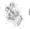
- Figures 2 and 3 show the truck-receiving hopper 118 in its lowered working position
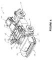
- Figures 4 and 5 show truck-receiving hopper 118 in its raised travel position.
- the raising of truck-receiving hopper 118 to a raised travel position i.e., with the base 124 of truck-receiving hopper 118 off the surface "S" of the roadway
- output end 122 of truck-unloading conveyor 120 is lowered from its working position shown in Figure 3 .
- Material transfer vehicle 110 includes operator's station 140 and an access stairway to the operator's station comprising at least one side stair portion and at least one conveyor step that is mounted on the upper side of the truck-unloading conveyor.
- this stairway comprises right side stair portion 141 and left side stair portion 142, and a plurality of conveyor steps 143, 144 and 145 that are each mounted across top panel 123 on the upper side of truck-unloading conveyor 120.
- Right side stair portion 141 includes fixed stair steps 146, 147, 148 and 149 that provide access to the upper side of the truck-unloading conveyor, and left side stair portion 142 is essentially identical to, although a mirror image of, right side stair portion 141. As shown in Figures 2 and 4 , right side stair portion 141 does not extend outwardly past right outer sidewall 150 of truck-receiving hopper 118. Similarly, left side stair portion 142 does not extend outwardly past left outer sidewall 152 of the truck-receiving hopper. Consequently, the access stairway is contained entirely within the periphery of material transfer vehicle 110.
- Conveyor steps 143, 144 and 145 are each mounted across top panel 123 on the upper side of truck-unloading conveyor 120.
- conveyor steps 143, 144 and 145 are mounted on truck-unloading conveyor 120 so as to be generally horizontal when truck-receiving hopper 118 is in its lowered or working position, as best shown in Figure 3 , and to pivot or move away from a horizontal orientation, as best shown in Figure 5 , as truck-receiving hopper 118 is raised and truck-unloading conveyor 120 is pivoted from the working position shown in Figure 3 to the travel position shown in Figure 5 .
- the invention thus provides a stairway for access to the operator's station of a material transfer vehicle, or other working machine having a conveyor adjacent to and below the operator's station.
- the invention may also be employed on a material transfer vehicle having a surge hopper (not shown).
- the preferred access stairway of the invention is located entirely within the outer periphery of the material transfer vehicle or other working machine and is easy and safe to use.
Landscapes
- Engineering & Computer Science (AREA)
- Mechanical Engineering (AREA)
- Architecture (AREA)
- Civil Engineering (AREA)
- Structural Engineering (AREA)
- Road Paving Machines (AREA)
- Vehicle Step Arrangements And Article Storage (AREA)
Description
- This invention relates generally to a material transfer vehicle that is adapted for transferring asphalt paving material from an asphalt supply truck to an asphalt paving machine. More particularly, the invention relates to a material transfer vehicle having an access stairway by which the operator may enter the operator's station.
- The traditional process for paving roadways with asphalt paving material is generally carried out by an asphalt paving machine and a number of supply trucks which transport the asphalt paving material from an asphalt production plant to the paving machine. The paving machine generally is self-propelled and driven by a wheeled or tracked drive system. A hopper is located at the front end of the machine to receive asphalt paving material from a dump-type supply truck, and a floating screed is located at the rear end of the machine to form the asphalt mat. A conveyor delivers the asphalt paving material from the hopper to the road base just ahead of the screed, where a distributing auger distributes the asphalt paving material across the roadway in front of the screed.
- In recent years, material transfer vehicles have been frequently used to shuttle asphalt paving material between the supply trucks and the paving machine. A self-propelled material transfer vehicle typically includes a large-capacity truck-receiving hopper and an inclined truck-unloading conveyor extending upwardly from this hopper. Asphalt paving material is dumped from a supply truck into the truck-receiving hopper. Thereafter, it is carried upwardly by the truck-unloading conveyor from the truck-receiving hopper and discharged off the elevated output end of the truck-unloading conveyor into a chute mounted on the lower end of a paver-loading conveyor, or into an intermediate surge hopper that is sized to hold the entire load of a delivery truck. The discharge of asphalt material off the elevated output end of the truck-unloading conveyor so that it may fall under the influence of gravity into a chute or surge hopper assists in preventing undesirable segregation of the various particulate components of the asphalt paving material by particle size.
- Material transfer vehicles of the type that are equipped with a surge hopper typically include a conveyor in the surge hopper that is adapted to transfer the asphalt paving material to a paver-loading conveyor. Paver-loading conveyors mounted on material transfer vehicles with and without surge hoppers are generally pivotable about an essentially vertical axis so that the transfer vehicle can be positioned alongside an asphalt paving machine that is laying an asphalt mat and rapidly discharge asphalt paving material into the hopper of the paving machine as the material transfer vehicle moves with the paving machine along the roadway. Because of its rapid loading and unloading capabilities, a material transfer vehicle can rapidly shuttle between delivery trucks at a pick-up point and an asphalt paving machine that is laying an asphalt mat at a paving site so that there is less likelihood that the paving machine will have to stop paving because of a lack of asphalt paving material.
- A material transfer vehicle is operated by an operator in an operator's station that is located high enough to allow for unobstructed viewing of the roadway and the loading of the truck-receiving hopper. Conventionally, the operator's station is accessed by a vertical ladder located on the side or end of the operator's station. A stairway is easier and safer to use than a vertical ladder; however, a conventional stairway would occupy too much space and/or would protrude outside the periphery of the material transfer vehicle, thereby creating its own safety hazard. It would be advantageous if a stairway could be devised that would be located entirely within the periphery of the material transfer vehicle and would be easy and safe to use.
-
US 7160056 B1 discloses a material transfer vehicle for transporting asphalt from a delivery truck to a paving machine includes a frame and a vehicle drive system. A truck-unloading conveyor is mounted on the frame and can be raised to a travel position. An operator's station is mounted above the truck-unloading conveyor on supports, including a stairway support, that are attached to the frame. - An aim of the present invention is to provide a stairway for the operator's station of a material transfer vehicle that is located entirely within the periphery of the material transfer vehicle and is easy and safe to use. Other advantages and features of this invention will become apparent from an examination of the drawings and the ensuing description.
- The use of the terms "a", "an", "the" and similar terms in the context of describing the invention are to be construed to cover both the singular and the plural, unless otherwise indicated herein or clearly contradicted by context. The terms "comprising", "having", "including" and "containing" are to be construed as open-ended terms (i.e., meaning "including, but not limited to,") unless otherwise noted. The terms "substantially", "generally" and other words of degree are relative modifiers intended to indicate permissible variation from the characteristic so modified. The use of such terms in describing a physical or functional characteristic of the invention is not intended to limit such characteristic to the absolute value which the term modifies, but rather to provide an approximation of the value of such physical or functional characteristic.
- Terms concerning attachments, coupling and the like, such as "connected" and "interconnected", refer to a relationship wherein structures are secured or attached to one another either directly or indirectly through intervening structures, as well as both moveable and rigid attachments or relationships, unless otherwise specified herein or clearly indicated by context. The term "operatively connected" is such an attachment, coupling or connection that allows the pertinent structures to operate as intended by virtue of that relationship.
- The use of any and all examples or exemplary language (e.g., "such as" and "preferably") herein is intended merely to better illuminate the invention and the preferred embodiment thereof, and not to place a limitation on the scope of the invention. Nothing in the specification should be construed as indicating any element as essential to the practice of the invention unless so stated with specificity.
- Several terms are specifically defined herein. These terms are to be given their broadest reasonable construction consistent with such definitions, as follows:
The term "asphalt paving material" refers to a paving mixture that is comprised of an asphalt binder and crushed stone and/or other aggregate materials of varying particle size, and which is used for paving purposes. - The term "asphalt binder" and similar terms refer to a sticky, black, highly viscous liquid or semi-solid petroleum distillate that is used in combination with aggregate materials in the production of asphalt paving material. Asphalt binders may comprise asphalt cement, cutback asphalt, an asphalt cement emulsion and/or foamed asphalt cement.
- The terms "asphalt paving machine", "paving machine" and "paver" refer to a finishing machine for applying asphalt paving material to form an asphalt mat on a roadway, parking lot or similar surface. An asphalt paving machine is typically a self-propelled vehicle having a hopper at one end for receiving asphalt paving material and a floating screed at the other end for forming an asphalt mat.
- The term "asphalt mat" refers to a layer of asphalt paving material such as is applied by an asphalt paving machine to produce a roadway, parking lot or similar surface.
- The term "material transfer vehicle" refers to a vehicle that is adapted to receive asphalt paving material from a supply truck and to convey the asphalt paving material to the hopper of an asphalt paving machine at a paving site. A material transfer vehicle includes a truck-receiving hopper that is adapted to receive asphalt material from a dump-type supply truck, and a truck-unloading conveyor that is adapted to receive asphalt material from the truck-receiving hopper.
- The term "generally horizontal" and similar terms, when used with respect to a material transfer vehicle or a component of a material transfer vehicle, refer to a direction or orientation that is generally parallel to the frame of the material transfer vehicle on which the wheel sets or track drives are mounted.
- The term "upper" as used herein to describe a relative direction on or in connection with a material transfer vehicle or a truck-unloading conveyor thereof, refers to a direction away from the roadway on which the material transfer vehicle is being operated.
- The term "left", as used herein to indicate a side or direction of a material transfer vehicle or a component thereof, refers to the side or direction that is to the left of an observer who is facing the end of the material transfer vehicle on which the truck-receiving hopper is mounted.
- The term "right", as used herein to indicate a side or direction of a material transfer vehicle or a component thereof, refers to the side or direction that is opposite the left side.
- The terms "actuator" and "linear actuator" refer to an electric, pneumatic, hydraulic, electro-hydraulic or mechanical device that generates force which is directed in a straight line. One common example of a linear actuator is a double-acting hydraulic or pneumatic actuator which includes a cylinder, a piston within the cylinder, and a rod attached to the piston. By increasing the pressure within the cylinder on one side of the piston (over that on the opposite side of the piston), the rod will extend from the cylinder or retract into the cylinder. The term "actuator" includes but is not limited to a device having two rod ends with a piston mounted therebetween, which device is adapted to selectively generate a force in a first direction or in a second direction that is disposed 180° away from the first direction.
- According to the present invention, the material transfer vehicle comprises: (a) a frame having a frame longitudinal axis; (b) an operator's station that is mounted on the frame; (c) a conveyor: (i) having an upper side and a conveyor longitudinal axis; (ii) which is mounted on the frame; (iii) which is located adjacent to and below the operator's station; (iv) which is adapted to be moved between a working position in which the conveyor longitudinal axis forms a working angle with the frame longitudinal axis and a travel position in which the conveyor longitudinal axis forms a travel angle with the frame longitudinal axis; (d) an access stairway to the operator's station comprising a side stair portion; wherein said access stairway also comprises a conveyor step that is mounted on the upper side of the conveyor, said conveyor step being mounted so as to be generally horizontal when the conveyor is in its working position.
- A preferred embodiment of the invention comprises a stairway that includes at least one side stair portion and at least one conveyor step that is mounted on the upper side of the truck-unloading conveyor of a material transfer vehicle. The conveyor step on the upper side of the truck-unloading conveyor is mounted so as to be generally horizontal when the truck-unloading conveyor is in its lowered or working position. The truck-unloading conveyor is adjacent to and below the operator's station, and the stairway is located entirely within the outer periphery of the material transfer vehicle.
- In order to facilitate an understanding of the invention, the preferred embodiment of the invention, as well as the best mode known by the inventor for carrying out the invention, is illustrated in the drawings, and a detailed description thereof follows. It is not intended, however, that the invention be limited to the particular embodiment described or to use in connection with the apparatus illustrated herein. Therefore, the scope of the invention contemplated by the inventor includes all equivalents of the subject matter as well as various modifications and alternative embodiments, within the scope of the appended claims.
- The presently preferred embodiment of the invention is illustrated in the accompanying drawings, in which like reference numerals represent like parts throughout, and wherein:
-
Figure 1 is a side view of a conventional material transfer vehicle that is equipped with a vertically oriented ladder that provides access to the operator's station. -
Figure 2 is a perspective view of a material transfer vehicle that includes the invention, showing the truck-receiving hopper in the lowered working position. -
Figure 3 is a side view of the material transfer vehicle shown inFigure 2 . -
Figure 4 is a perspective view of a material transfer vehicle that includes the invention, showing the truck-receiving hopper in the raised travel position. -
Figure 5 is a side view of the material transfer vehicle shown inFigure 4 . - This description of a preferred embodiment of the invention is intended to be read in connection with the accompanying drawings, which are to be considered part of the entire written description of this invention. The drawing figures are not necessarily to scale, and certain features of the invention may be shown exaggerated in scale or in somewhat schematic form in the interest of clarity and conciseness.
- As shown in
Figure 1 , a conventional self-propelledmaterial transfer vehicle 10 includesframe 12 that is supported on the roadway surface "S" byfirst wheel set 14 andsecond wheel set 16. Each of the wheel sets is driven by a hydraulic motor (not shown) that is supplied with fluid under pressure by one or more hydraulic pumps (also not shown).Vehicle 10 includes truck-receivinghopper 18 for receiving asphalt paving material from a supply truck (not shown). Truck-unloadingconveyor 20 is operatively attached to the truck-receiving hopper and is adapted to convey asphalt paving material from truck-receivinghopper 18 upwardly to output end 22 of truck-unloadingconveyor 20. - As shown in
Figure 1 , truck-receivinghopper 18 is disposed in its lowered working position. Although not shown inFigure 1 , truck-receivinghopper 18 may be lifted to a raised travel position (i.e., with thebase 24 of truck-receivinghopper 18 off the surface "S" of the roadway so thatmaterial transfer vehicle 10 may travel along the roadway between a supply truck and an asphalt paving machine). When truck-receivinghopper 18 is raised to the travel position, the angle betweenlongitudinal axis 26 offrame 12 andlongitudinal axis 28 of truck-unloadingconveyor 20 will change from the working angle shown inFigure 1 to a smaller angle (not shown) when the truck-receiving hopper is in the raised travel position (also not shown). - Asphalt paving material is carried upwardly on truck-unloading
conveyor 20 to itselevated output end 22, from which it will fall intochute 30 onlower input end 32 of paver-loading conveyor 34. Asphalt paving material falling intochute 30 is conveyed upwardly by paver-loading conveyor 34. Paver-loading conveyor 34 is mounted for pivotal movement about a horizontal pivot axis atlower input end 32 by means of one or more linearactuators including actuator 36 so that theoutput end 38 of paver-loading conveyor 34 may be raised and lowered.Conveyor 34 is also adapted for side-to-side movement about a vertical axis by operation of one or more additional actuators (not shown). Asphalt paving material that falls intochute 30 on paver-loading conveyor 34 is carried upwardly to output end 38 of paver-loading conveyor 34, from which it will fall into the hopper of an asphalt paving machine (not shown). -
Material transfer vehicle 10 also includes operator'sstation 40 from which all operating functions of the vehicle may be controlled. Operator'sstation 40 is accessed by conventionalvertical ladder 42. -
Figures 2-5 illustrate a preferred embodiment of the invention. As shown therein, a working machine comprisingmaterial transfer vehicle 110 is substantially similar tomaterial transfer vehicle 10, except that: (a) the paver-loading conveyor is not shown; and (b) a stairway (described in more detail hereinafter) is provided for access to the operator's station, instead ofvertical ladder 42. -
Material transfer vehicle 110 includesframe 112 that is supported on the roadway surface "S" byfirst wheel set 114 andsecond wheel set 116. Each of the wheel sets is driven by one or more hydraulic motors (not shown) that are supplied with fluid under pressure by one or more hydraulic pumps (also not shown). Of course, as will be apparent to those having ordinary skill in the art to which the invention relates, the invention may also be employed on a material transfer vehicle or other working machine that is driven by electric motors or a transmission connected to an internal combustion engine. The invention may also be employed on a material transfer vehicle having track drive assemblies instead of wheel sets. -
Vehicle 110 includes truck-receivinghopper 118 for receiving asphalt paving material from a supply truck (not shown), and truck-unloadingconveyor 120 that is operatively attached to the truck-receiving hopper and is adapted to convey asphalt paving material from truck-receivinghopper 118 upwardly to output end 122 of truck-unloadingconveyor 120. Truck-unloadingconveyor 120 is a conventional slat-type conveyor that is partially enclosed bytop panel 123. -
Figures 2 and3 show the truck-receivinghopper 118 in its lowered working position, whileFigures 4 and5 show truck-receivinghopper 118 in its raised travel position. As best shown inFigure 5 , the raising of truck-receivinghopper 118 to a raised travel position (i.e., with thebase 124 of truck-receivinghopper 118 off the surface "S" of the roadway) will permitmaterial transfer vehicle 110 to travel along the roadway between a supply truck and an asphalt paving machine. When truck-receivinghopper 118 is raised to the travel position,output end 122 of truck-unloadingconveyor 120 is lowered from its working position shown inFigure 3 . Consequently, the movement of truck-receivinghopper 118 and truck-unloadingconveyor 120 between the working position shown inFigure 3 and the travel position shown inFigure 5 will cause the angle θ betweenlongitudinal axis 126 offrame 112 andlongitudinal axis 128 of truck-unloadingconveyor 120 to change between working angle θW (approximately 25°) when the truck-receiving hopper and the truck-unloading conveyor are in the working position shown inFigure 3 and travel angle θT (approximately 15°) when the truck-receiving hopper and the truck-unloading conveyor are in the travel position shown inFigure 5 . -
Material transfer vehicle 110 includes operator'sstation 140 and an access stairway to the operator's station comprising at least one side stair portion and at least one conveyor step that is mounted on the upper side of the truck-unloading conveyor. Preferably, as shown inFigures 2-5 , this stairway comprises rightside stair portion 141 and leftside stair portion 142, and a plurality of conveyor steps 143, 144 and 145 that are each mounted acrosstop panel 123 on the upper side of truck-unloadingconveyor 120. Rightside stair portion 141 includes fixed stair steps 146, 147, 148 and 149 that provide access to the upper side of the truck-unloading conveyor, and leftside stair portion 142 is essentially identical to, although a mirror image of, rightside stair portion 141. As shown inFigures 2 and4 , rightside stair portion 141 does not extend outwardly past rightouter sidewall 150 of truck-receivinghopper 118. Similarly, leftside stair portion 142 does not extend outwardly past leftouter sidewall 152 of the truck-receiving hopper. Consequently, the access stairway is contained entirely within the periphery ofmaterial transfer vehicle 110. - Conveyor steps 143, 144 and 145 are each mounted across
top panel 123 on the upper side of truck-unloadingconveyor 120. Preferably, conveyor steps 143, 144 and 145 are mounted on truck-unloadingconveyor 120 so as to be generally horizontal when truck-receivinghopper 118 is in its lowered or working position, as best shown inFigure 3 , and to pivot or move away from a horizontal orientation, as best shown inFigure 5 , as truck-receivinghopper 118 is raised and truck-unloadingconveyor 120 is pivoted from the working position shown inFigure 3 to the travel position shown inFigure 5 . - The invention thus provides a stairway for access to the operator's station of a material transfer vehicle, or other working machine having a conveyor adjacent to and below the operator's station. The invention may also be employed on a material transfer vehicle having a surge hopper (not shown). The preferred access stairway of the invention is located entirely within the outer periphery of the material transfer vehicle or other working machine and is easy and safe to use.
- Although this description contains many specifics, these should not be construed as limiting the scope of the invention but as merely providing illustrations of the presently preferred embodiment thereof, as well as the best mode contemplated by the inventors of carrying out the invention. The invention, as described and claimed herein, is susceptible to various modifications and adaptations, as would be understood by those having ordinary skill in the art to which the invention relates.
Claims (9)
- A material transfer vehicle (110) comprising:(a) a frame (112) having a frame longitudinal axis (126);(b) an operator's station (140) that is mounted on the frame (112);(c) a conveyor (120):(i) having an upper side and a conveyor longitudinal axis (128);(ii) which is mounted on the frame (112);(iii) which is located adjacent to and below the operator's station (140);(iv) which is adapted to be moved between a working position in which the conveyor longitudinal axis (128) forms a working angle (θw) with the frame longitudinal axis (126) and a travel position in which the conveyor longitudinal axis (128) forms a travel angle (θT) with the frame longitudinal axis (126);(d) an access stairway to the operator's station (140) comprising a side stair portion (141, 142);wherein the term horizontal refers to a direction or orientation that is generally parallel to the frame (112) of the material transfer vehicle (110).
characterized in that:
said access stairway also comprises a conveyor step (143, 144, 145) that is mounted on the upper side of the conveyor (120), said conveyor step (143,144,145) being mounted so as to be generally horizontal when the conveyor (120) is in its working position, - The material transfer vehicle of claim 1 wherein the conveyor step (143, 144, 145) is mounted on the upper side of the conveyor (120) so as to pivot away from a horizontal orientation when the conveyor (120) is in its travel position.
- The material transfer vehicle of claim 1 wherein:(a) the material transfer vehicle (110) has an outer periphery;(b) the access stairway is located entirely within the outer periphery of the material transfer vehicle (110).
- The material transfer vehicle of claim 1 wherein the access stairway comprises:(a) a right side stair portion (141) having a plurality of fixed stair steps (146, 147, 148, 149);(b) a left side stair portion (142) having a plurality of fixed stair steps;(c) a plurality of conveyor steps (143,144,145) that are each mounted on the upper side of the conveyor (120).
- The material transfer vehicle of claim 4 wherein:(a) the upper side of the conveyor (120) includes a top panel (123);(b) the plurality of conveyor steps (143,144,145) on the upper side of the conveyor (120) are each mounted across the top panel (123) so as to be generally horizontal when the conveyor (120) is in its working position, and to pivot away from a horizontal orientation when the conveyor (120) is moved to its travel position.
- A material transfer vehicle of claim 1 having an outer periphery and further comprising:(a) a truck-receiving hopper (118) for receiving asphalt paving material from a supply truck;(b) the conveyor (120) being a truck-unloading conveyor:(i) which is operatively attached to the truck-receiving hopper (118);(ii) which is adapted to convey asphalt paving material from the truck- receiving hopper (118);(c) the access stairway to the operator's station (140) comprising:(i) a right side stair portion (141) having a plurality of fixed stair steps (146,147,148,149) that provide access to the upper side of the truck-unloading conveyor (120);(ii) a left side stair portion (143) having a plurality of fixed stair steps that provide access to the upper side of the truck-unloading conveyor (120);(iii) a plurality of said conveyor steps (143, 144, 145) that are each mounted across the upper side of the truck-unloading conveyor (120).
- The material transfer vehicle of claim 6 wherein the access stairway is located entirely within the outer periphery of the material transfer vehicle (110).
- The material transfer vehicle of claim 4 or 6 wherein the left side stair portion (142) is essentially identical to, although a mirror image of, the right side stair portion (141).
- The material transfer vehicle of claim 6 wherein the plurality of conveyor steps (143,144,145) that are mounted across the upper side of the conveyor (120) are each mounted so as to be generally horizontal when the conveyor (120) is in its working position, and to pivot away from a horizontal orientation as the conveyor (120) is moved to its travel position.
Applications Claiming Priority (2)
| Application Number | Priority Date | Filing Date | Title |
|---|---|---|---|
| US201662407689P | 2016-10-13 | 2016-10-13 | |
| PCT/US2017/049941 WO2018071109A1 (en) | 2016-10-13 | 2017-09-01 | Access stairway for material transfer vehicle |
Publications (3)
| Publication Number | Publication Date |
|---|---|
| EP3526408A1 EP3526408A1 (en) | 2019-08-21 |
| EP3526408A4 EP3526408A4 (en) | 2020-06-17 |
| EP3526408B1 true EP3526408B1 (en) | 2021-07-21 |
Family
ID=61903013
Family Applications (1)
| Application Number | Title | Priority Date | Filing Date |
|---|---|---|---|
| EP17859421.4A Active EP3526408B1 (en) | 2016-10-13 | 2017-09-01 | Material transfer vehicle |
Country Status (8)
| Country | Link |
|---|---|
| US (1) | US9956917B1 (en) |
| EP (1) | EP3526408B1 (en) |
| CN (1) | CN109844225A (en) |
| AU (1) | AU2017342719B2 (en) |
| CA (1) | CA3036806C (en) |
| ES (1) | ES2886135T3 (en) |
| RU (1) | RU2755305C2 (en) |
| WO (1) | WO2018071109A1 (en) |
Families Citing this family (7)
| Publication number | Priority date | Publication date | Assignee | Title |
|---|---|---|---|---|
| JP6550359B2 (en) * | 2016-09-21 | 2019-07-24 | 日立建機株式会社 | Construction machinery |
| WO2018222426A1 (en) | 2017-06-01 | 2018-12-06 | Roadtec, Inc. | Quick-change attachment for material transfer vehicle |
| US10246835B1 (en) * | 2017-11-02 | 2019-04-02 | Roadtec, Inc. | Method and apparatus for spreading chips on roadway using foamed asphalt cement |
| US10487462B2 (en) * | 2017-11-02 | 2019-11-26 | Roadtec, Inc. | Method and apparatus for spreading chips on roadway |
| US10760226B2 (en) * | 2017-12-29 | 2020-09-01 | Guntert & Zimmerman Const. Div., Inc. | Material placer and high volume supply hopper |
| EP4018040B1 (en) * | 2019-08-23 | 2024-10-09 | Roadtec, Inc. | Material transfer vehicle with ground operator station |
| US11858561B2 (en) | 2019-10-23 | 2024-01-02 | Roadtec, Inc. | Material transfer vehicle with movable operator's platform |
Family Cites Families (18)
| Publication number | Priority date | Publication date | Assignee | Title |
|---|---|---|---|---|
| US5035534A (en) * | 1987-08-25 | 1991-07-30 | Barber-Greene Company | Apparatus for transferring an asphalt-aggregate mixture |
| KR100534385B1 (en) * | 2003-09-09 | 2005-12-08 | 기아자동차주식회사 | Apparatus for mounting and taking away ladder for vehicle |
| US7422096B2 (en) * | 2003-11-14 | 2008-09-09 | Crookston Anthony J | Extension for conveyor |
| US7160056B1 (en) * | 2005-03-11 | 2007-01-09 | Roadtee, Inc. | Material transfer vehicle for use in asphalt paving |
| RU2411320C2 (en) * | 2006-12-06 | 2011-02-10 | Роудтек, Инк. | Transfer vehicle to carry material used for asphalt pavement laying |
| US7785034B2 (en) * | 2008-06-26 | 2010-08-31 | Weiler, Inc. | Desegregation system |
| US7992704B2 (en) | 2008-08-07 | 2011-08-09 | Weiler, Inc. | Conveyor clean-out for material transport vehicles |
| CN201420221Y (en) * | 2009-04-29 | 2010-03-10 | 刘廷国 | Heat insulating asphalt truck |
| RU145169U1 (en) * | 2013-09-18 | 2014-09-10 | Российская Федерация,от имени которой выступает Министерство промышленности и торговли Российской Федерации | ASPHALT MIXER LOADER |
| CN103741951B (en) * | 2014-01-27 | 2017-06-27 | 深圳市蛇口招商港湾工程有限公司 | The self-feeding material chamber rotor external-drive vehicle-mounted pulp shooting machine of concrete dry wet feed |
| DE102014003155A1 (en) * | 2014-03-03 | 2015-09-03 | Liebherr-Mining Equipment Colmar Sas | Work machine, in particular dump truck or truck |
| US20140216849A1 (en) | 2014-04-11 | 2014-08-07 | Caterpillar Paving Products Inc. | Coupling assembly for walkway in paving machine |
| DE112016000713B4 (en) * | 2015-02-11 | 2020-11-19 | Roadtec Inc. | Auto-calibration of an automatic leveling control system in a work machine |
| US9743575B2 (en) * | 2015-03-02 | 2017-08-29 | Deere & Company | Commodity cart tank with upper and lower fill openings |
| CN205134142U (en) * | 2015-10-27 | 2016-04-06 | 江苏宝利国际投资股份有限公司 | Pitch storage container case |
| CN205344716U (en) * | 2015-12-18 | 2016-06-29 | 北京砼友混凝土浇筑技术有限公司 | Transport tank car |
| US9994159B2 (en) * | 2016-02-29 | 2018-06-12 | Deere & Company | Multi-position stair assembly for work vehicles |
| US20160326802A1 (en) * | 2016-07-19 | 2016-11-10 | Caterpillar Inc. | Access system for machine |
-
2017
- 2017-09-01 US US15/694,464 patent/US9956917B1/en active Active
- 2017-09-01 AU AU2017342719A patent/AU2017342719B2/en active Active
- 2017-09-01 WO PCT/US2017/049941 patent/WO2018071109A1/en not_active Ceased
- 2017-09-01 ES ES17859421T patent/ES2886135T3/en active Active
- 2017-09-01 RU RU2019109048A patent/RU2755305C2/en not_active Application Discontinuation
- 2017-09-01 CA CA3036806A patent/CA3036806C/en active Active
- 2017-09-01 EP EP17859421.4A patent/EP3526408B1/en active Active
- 2017-09-01 CN CN201780063707.9A patent/CN109844225A/en active Pending
Also Published As
| Publication number | Publication date |
|---|---|
| CA3036806C (en) | 2021-05-18 |
| AU2017342719B2 (en) | 2019-12-12 |
| RU2755305C2 (en) | 2021-09-15 |
| WO2018071109A1 (en) | 2018-04-19 |
| ES2886135T3 (en) | 2021-12-16 |
| RU2019109048A3 (en) | 2021-04-12 |
| CN109844225A (en) | 2019-06-04 |
| US20180105116A1 (en) | 2018-04-19 |
| AU2017342719A1 (en) | 2019-05-02 |
| US9956917B1 (en) | 2018-05-01 |
| EP3526408A1 (en) | 2019-08-21 |
| EP3526408A4 (en) | 2020-06-17 |
| RU2019109048A (en) | 2020-11-14 |
| CA3036806A1 (en) | 2018-04-19 |
Similar Documents
| Publication | Publication Date | Title |
|---|---|---|
| CA3036806C (en) | Access stairway for material transfer vehicle | |
| EP3237253B1 (en) | Material transfer vehicle having an expandable truck-receiving hopper | |
| CA3062182C (en) | Quick-change attachment for material transfer vehicle | |
| AU2018328001B2 (en) | Combination door/platform for maintenance access for conveyor of material transfer vehicle | |
| US11866888B2 (en) | Material transfer vehicle with ground operator station | |
| CA3121197C (en) | Material transfer vehicle with movable operator's platform | |
| US20210107738A1 (en) | Material transfer vehicle with modular engine assembly |
Legal Events
| Date | Code | Title | Description |
|---|---|---|---|
| STAA | Information on the status of an ep patent application or granted ep patent |
Free format text: STATUS: THE INTERNATIONAL PUBLICATION HAS BEEN MADE |
|
| PUAI | Public reference made under article 153(3) epc to a published international application that has entered the european phase |
Free format text: ORIGINAL CODE: 0009012 |
|
| STAA | Information on the status of an ep patent application or granted ep patent |
Free format text: STATUS: REQUEST FOR EXAMINATION WAS MADE |
|
| 17P | Request for examination filed |
Effective date: 20190319 |
|
| AK | Designated contracting states |
Kind code of ref document: A1 Designated state(s): AL AT BE BG CH CY CZ DE DK EE ES FI FR GB GR HR HU IE IS IT LI LT LU LV MC MK MT NL NO PL PT RO RS SE SI SK SM TR |
|
| AX | Request for extension of the european patent |
Extension state: BA ME |
|
| DAV | Request for validation of the european patent (deleted) | ||
| DAX | Request for extension of the european patent (deleted) | ||
| REG | Reference to a national code |
Ref country code: DE Ref legal event code: R079 Ref document number: 602017042684 Country of ref document: DE Free format text: PREVIOUS MAIN CLASS: E01C0019080000 Ipc: B60P0001380000 |
|
| A4 | Supplementary search report drawn up and despatched |
Effective date: 20200520 |
|
| RIC1 | Information provided on ipc code assigned before grant |
Ipc: B60R 3/02 20060101ALI20200514BHEP Ipc: B60R 3/00 20060101ALI20200514BHEP Ipc: B60P 1/38 20060101AFI20200514BHEP Ipc: E01C 19/48 20060101ALI20200514BHEP Ipc: B65G 41/00 20060101ALI20200514BHEP |
|
| GRAP | Despatch of communication of intention to grant a patent |
Free format text: ORIGINAL CODE: EPIDOSNIGR1 |
|
| STAA | Information on the status of an ep patent application or granted ep patent |
Free format text: STATUS: GRANT OF PATENT IS INTENDED |
|
| INTG | Intention to grant announced |
Effective date: 20210325 |
|
| GRAS | Grant fee paid |
Free format text: ORIGINAL CODE: EPIDOSNIGR3 |
|
| GRAA | (expected) grant |
Free format text: ORIGINAL CODE: 0009210 |
|
| STAA | Information on the status of an ep patent application or granted ep patent |
Free format text: STATUS: THE PATENT HAS BEEN GRANTED |
|
| AK | Designated contracting states |
Kind code of ref document: B1 Designated state(s): AL AT BE BG CH CY CZ DE DK EE ES FI FR GB GR HR HU IE IS IT LI LT LU LV MC MK MT NL NO PL PT RO RS SE SI SK SM TR |
|
| REG | Reference to a national code |
Ref country code: GB Ref legal event code: FG4D |
|
| REG | Reference to a national code |
Ref country code: CH Ref legal event code: EP |
|
| REG | Reference to a national code |
Ref country code: DE Ref legal event code: R096 Ref document number: 602017042684 Country of ref document: DE |
|
| REG | Reference to a national code |
Ref country code: AT Ref legal event code: REF Ref document number: 1412319 Country of ref document: AT Kind code of ref document: T Effective date: 20210815 |
|
| REG | Reference to a national code |
Ref country code: IE Ref legal event code: FG4D |
|
| REG | Reference to a national code |
Ref country code: SE Ref legal event code: TRGR |
|
| REG | Reference to a national code |
Ref country code: LT Ref legal event code: MG9D |
|
| REG | Reference to a national code |
Ref country code: NL Ref legal event code: MP Effective date: 20210721 |
|
| REG | Reference to a national code |
Ref country code: AT Ref legal event code: MK05 Ref document number: 1412319 Country of ref document: AT Kind code of ref document: T Effective date: 20210721 |
|
| REG | Reference to a national code |
Ref country code: ES Ref legal event code: FG2A Ref document number: 2886135 Country of ref document: ES Kind code of ref document: T3 Effective date: 20211216 |
|
| PG25 | Lapsed in a contracting state [announced via postgrant information from national office to epo] |
Ref country code: RS Free format text: LAPSE BECAUSE OF FAILURE TO SUBMIT A TRANSLATION OF THE DESCRIPTION OR TO PAY THE FEE WITHIN THE PRESCRIBED TIME-LIMIT Effective date: 20210721 Ref country code: HR Free format text: LAPSE BECAUSE OF FAILURE TO SUBMIT A TRANSLATION OF THE DESCRIPTION OR TO PAY THE FEE WITHIN THE PRESCRIBED TIME-LIMIT Effective date: 20210721 Ref country code: FI Free format text: LAPSE BECAUSE OF FAILURE TO SUBMIT A TRANSLATION OF THE DESCRIPTION OR TO PAY THE FEE WITHIN THE PRESCRIBED TIME-LIMIT Effective date: 20210721 Ref country code: LT Free format text: LAPSE BECAUSE OF FAILURE TO SUBMIT A TRANSLATION OF THE DESCRIPTION OR TO PAY THE FEE WITHIN THE PRESCRIBED TIME-LIMIT Effective date: 20210721 Ref country code: BG Free format text: LAPSE BECAUSE OF FAILURE TO SUBMIT A TRANSLATION OF THE DESCRIPTION OR TO PAY THE FEE WITHIN THE PRESCRIBED TIME-LIMIT Effective date: 20211021 Ref country code: AT Free format text: LAPSE BECAUSE OF FAILURE TO SUBMIT A TRANSLATION OF THE DESCRIPTION OR TO PAY THE FEE WITHIN THE PRESCRIBED TIME-LIMIT Effective date: 20210721 Ref country code: PT Free format text: LAPSE BECAUSE OF FAILURE TO SUBMIT A TRANSLATION OF THE DESCRIPTION OR TO PAY THE FEE WITHIN THE PRESCRIBED TIME-LIMIT Effective date: 20211122 Ref country code: NO Free format text: LAPSE BECAUSE OF FAILURE TO SUBMIT A TRANSLATION OF THE DESCRIPTION OR TO PAY THE FEE WITHIN THE PRESCRIBED TIME-LIMIT Effective date: 20211021 Ref country code: NL Free format text: LAPSE BECAUSE OF FAILURE TO SUBMIT A TRANSLATION OF THE DESCRIPTION OR TO PAY THE FEE WITHIN THE PRESCRIBED TIME-LIMIT Effective date: 20210721 |
|
| PG25 | Lapsed in a contracting state [announced via postgrant information from national office to epo] |
Ref country code: PL Free format text: LAPSE BECAUSE OF FAILURE TO SUBMIT A TRANSLATION OF THE DESCRIPTION OR TO PAY THE FEE WITHIN THE PRESCRIBED TIME-LIMIT Effective date: 20210721 Ref country code: LV Free format text: LAPSE BECAUSE OF FAILURE TO SUBMIT A TRANSLATION OF THE DESCRIPTION OR TO PAY THE FEE WITHIN THE PRESCRIBED TIME-LIMIT Effective date: 20210721 Ref country code: GR Free format text: LAPSE BECAUSE OF FAILURE TO SUBMIT A TRANSLATION OF THE DESCRIPTION OR TO PAY THE FEE WITHIN THE PRESCRIBED TIME-LIMIT Effective date: 20211022 |
|
| REG | Reference to a national code |
Ref country code: DE Ref legal event code: R097 Ref document number: 602017042684 Country of ref document: DE |
|
| PG25 | Lapsed in a contracting state [announced via postgrant information from national office to epo] |
Ref country code: DK Free format text: LAPSE BECAUSE OF FAILURE TO SUBMIT A TRANSLATION OF THE DESCRIPTION OR TO PAY THE FEE WITHIN THE PRESCRIBED TIME-LIMIT Effective date: 20210721 |
|
| REG | Reference to a national code |
Ref country code: CH Ref legal event code: PL |
|
| REG | Reference to a national code |
Ref country code: BE Ref legal event code: MM Effective date: 20210930 |
|
| PLBE | No opposition filed within time limit |
Free format text: ORIGINAL CODE: 0009261 |
|
| STAA | Information on the status of an ep patent application or granted ep patent |
Free format text: STATUS: NO OPPOSITION FILED WITHIN TIME LIMIT |
|
| PG25 | Lapsed in a contracting state [announced via postgrant information from national office to epo] |
Ref country code: SM Free format text: LAPSE BECAUSE OF FAILURE TO SUBMIT A TRANSLATION OF THE DESCRIPTION OR TO PAY THE FEE WITHIN THE PRESCRIBED TIME-LIMIT Effective date: 20210721 Ref country code: SK Free format text: LAPSE BECAUSE OF FAILURE TO SUBMIT A TRANSLATION OF THE DESCRIPTION OR TO PAY THE FEE WITHIN THE PRESCRIBED TIME-LIMIT Effective date: 20210721 Ref country code: RO Free format text: LAPSE BECAUSE OF FAILURE TO SUBMIT A TRANSLATION OF THE DESCRIPTION OR TO PAY THE FEE WITHIN THE PRESCRIBED TIME-LIMIT Effective date: 20210721 Ref country code: MC Free format text: LAPSE BECAUSE OF FAILURE TO SUBMIT A TRANSLATION OF THE DESCRIPTION OR TO PAY THE FEE WITHIN THE PRESCRIBED TIME-LIMIT Effective date: 20210721 Ref country code: EE Free format text: LAPSE BECAUSE OF FAILURE TO SUBMIT A TRANSLATION OF THE DESCRIPTION OR TO PAY THE FEE WITHIN THE PRESCRIBED TIME-LIMIT Effective date: 20210721 Ref country code: CZ Free format text: LAPSE BECAUSE OF FAILURE TO SUBMIT A TRANSLATION OF THE DESCRIPTION OR TO PAY THE FEE WITHIN THE PRESCRIBED TIME-LIMIT Effective date: 20210721 Ref country code: AL Free format text: LAPSE BECAUSE OF FAILURE TO SUBMIT A TRANSLATION OF THE DESCRIPTION OR TO PAY THE FEE WITHIN THE PRESCRIBED TIME-LIMIT Effective date: 20210721 |
|
| 26N | No opposition filed |
Effective date: 20220422 |
|
| PG25 | Lapsed in a contracting state [announced via postgrant information from national office to epo] |
Ref country code: LU Free format text: LAPSE BECAUSE OF NON-PAYMENT OF DUE FEES Effective date: 20210901 Ref country code: IT Free format text: LAPSE BECAUSE OF FAILURE TO SUBMIT A TRANSLATION OF THE DESCRIPTION OR TO PAY THE FEE WITHIN THE PRESCRIBED TIME-LIMIT Effective date: 20210721 Ref country code: IE Free format text: LAPSE BECAUSE OF NON-PAYMENT OF DUE FEES Effective date: 20210901 Ref country code: FR Free format text: LAPSE BECAUSE OF NON-PAYMENT OF DUE FEES Effective date: 20210921 Ref country code: BE Free format text: LAPSE BECAUSE OF NON-PAYMENT OF DUE FEES Effective date: 20210930 |
|
| PG25 | Lapsed in a contracting state [announced via postgrant information from national office to epo] |
Ref country code: LI Free format text: LAPSE BECAUSE OF NON-PAYMENT OF DUE FEES Effective date: 20210930 Ref country code: CH Free format text: LAPSE BECAUSE OF NON-PAYMENT OF DUE FEES Effective date: 20210930 |
|
| PG25 | Lapsed in a contracting state [announced via postgrant information from national office to epo] |
Ref country code: CY Free format text: LAPSE BECAUSE OF FAILURE TO SUBMIT A TRANSLATION OF THE DESCRIPTION OR TO PAY THE FEE WITHIN THE PRESCRIBED TIME-LIMIT Effective date: 20210721 |
|
| P01 | Opt-out of the competence of the unified patent court (upc) registered |
Effective date: 20230526 |
|
| PG25 | Lapsed in a contracting state [announced via postgrant information from national office to epo] |
Ref country code: HU Free format text: LAPSE BECAUSE OF FAILURE TO SUBMIT A TRANSLATION OF THE DESCRIPTION OR TO PAY THE FEE WITHIN THE PRESCRIBED TIME-LIMIT; INVALID AB INITIO Effective date: 20170901 |
|
| PG25 | Lapsed in a contracting state [announced via postgrant information from national office to epo] |
Ref country code: MK Free format text: LAPSE BECAUSE OF FAILURE TO SUBMIT A TRANSLATION OF THE DESCRIPTION OR TO PAY THE FEE WITHIN THE PRESCRIBED TIME-LIMIT Effective date: 20210721 |
|
| PG25 | Lapsed in a contracting state [announced via postgrant information from national office to epo] |
Ref country code: MT Free format text: LAPSE BECAUSE OF FAILURE TO SUBMIT A TRANSLATION OF THE DESCRIPTION OR TO PAY THE FEE WITHIN THE PRESCRIBED TIME-LIMIT Effective date: 20210721 |
|
| PGFP | Annual fee paid to national office [announced via postgrant information from national office to epo] |
Ref country code: DE Payment date: 20250924 Year of fee payment: 9 |
|
| PGFP | Annual fee paid to national office [announced via postgrant information from national office to epo] |
Ref country code: GB Payment date: 20250821 Year of fee payment: 9 |
|
| PGFP | Annual fee paid to national office [announced via postgrant information from national office to epo] |
Ref country code: SE Payment date: 20250914 Year of fee payment: 9 |
|
| PG25 | Lapsed in a contracting state [announced via postgrant information from national office to epo] |
Ref country code: TR Free format text: LAPSE BECAUSE OF FAILURE TO SUBMIT A TRANSLATION OF THE DESCRIPTION OR TO PAY THE FEE WITHIN THE PRESCRIBED TIME-LIMIT Effective date: 20210721 |
|
| PGFP | Annual fee paid to national office [announced via postgrant information from national office to epo] |
Ref country code: ES Payment date: 20251008 Year of fee payment: 9 |
|
| REG | Reference to a national code |
Ref country code: DE Ref legal event code: R082 Ref document number: 602017042684 Country of ref document: DE Representative=s name: DR. RIEBLING & PARTNER PATENTANWAELTE MBB, DE |