EP3525954B1 - Device and method for the soft reduction of round-section metal products - Google Patents
Device and method for the soft reduction of round-section metal products Download PDFInfo
- Publication number
- EP3525954B1 EP3525954B1 EP17795065.6A EP17795065A EP3525954B1 EP 3525954 B1 EP3525954 B1 EP 3525954B1 EP 17795065 A EP17795065 A EP 17795065A EP 3525954 B1 EP3525954 B1 EP 3525954B1
- Authority
- EP
- European Patent Office
- Prior art keywords
- soft reduction
- rolls
- reduction unit
- round
- respect
- Prior art date
- Legal status (The legal status is an assumption and is not a legal conclusion. Google has not performed a legal analysis and makes no representation as to the accuracy of the status listed.)
- Active
Links
Images



Classifications
-
- B—PERFORMING OPERATIONS; TRANSPORTING
- B22—CASTING; POWDER METALLURGY
- B22D—CASTING OF METALS; CASTING OF OTHER SUBSTANCES BY THE SAME PROCESSES OR DEVICES
- B22D11/00—Continuous casting of metals, i.e. casting in indefinite lengths
- B22D11/12—Accessories for subsequent treating or working cast stock in situ
- B22D11/1206—Accessories for subsequent treating or working cast stock in situ for plastic shaping of strands
-
- B—PERFORMING OPERATIONS; TRANSPORTING
- B21—MECHANICAL METAL-WORKING WITHOUT ESSENTIALLY REMOVING MATERIAL; PUNCHING METAL
- B21B—ROLLING OF METAL
- B21B1/00—Metal-rolling methods or mills for making semi-finished products of solid or profiled cross-section; Sequence of operations in milling trains; Layout of rolling-mill plant, e.g. grouping of stands; Succession of passes or of sectional pass alternations
- B21B1/46—Metal-rolling methods or mills for making semi-finished products of solid or profiled cross-section; Sequence of operations in milling trains; Layout of rolling-mill plant, e.g. grouping of stands; Succession of passes or of sectional pass alternations for rolling metal immediately subsequent to continuous casting
-
- B—PERFORMING OPERATIONS; TRANSPORTING
- B22—CASTING; POWDER METALLURGY
- B22D—CASTING OF METALS; CASTING OF OTHER SUBSTANCES BY THE SAME PROCESSES OR DEVICES
- B22D11/00—Continuous casting of metals, i.e. casting in indefinite lengths
- B22D11/04—Continuous casting of metals, i.e. casting in indefinite lengths into open-ended moulds
- B22D11/041—Continuous casting of metals, i.e. casting in indefinite lengths into open-ended moulds for vertical casting
-
- B—PERFORMING OPERATIONS; TRANSPORTING
- B22—CASTING; POWDER METALLURGY
- B22D—CASTING OF METALS; CASTING OF OTHER SUBSTANCES BY THE SAME PROCESSES OR DEVICES
- B22D11/00—Continuous casting of metals, i.e. casting in indefinite lengths
- B22D11/12—Accessories for subsequent treating or working cast stock in situ
-
- B—PERFORMING OPERATIONS; TRANSPORTING
- B22—CASTING; POWDER METALLURGY
- B22D—CASTING OF METALS; CASTING OF OTHER SUBSTANCES BY THE SAME PROCESSES OR DEVICES
- B22D11/00—Continuous casting of metals, i.e. casting in indefinite lengths
- B22D11/12—Accessories for subsequent treating or working cast stock in situ
- B22D11/128—Accessories for subsequent treating or working cast stock in situ for removing
-
- B—PERFORMING OPERATIONS; TRANSPORTING
- B22—CASTING; POWDER METALLURGY
- B22D—CASTING OF METALS; CASTING OF OTHER SUBSTANCES BY THE SAME PROCESSES OR DEVICES
- B22D11/00—Continuous casting of metals, i.e. casting in indefinite lengths
- B22D11/12—Accessories for subsequent treating or working cast stock in situ
- B22D11/128—Accessories for subsequent treating or working cast stock in situ for removing
- B22D11/1282—Vertical casting and curving the cast stock to the horizontal
Definitions
- the present invention relates to a soft reduction device for round-section blumes or billets having liquid or partially liquid core, coming from a continuous casting machine, in order to compress the product in a controlled manner, thus reducing the liquid section and improving the inner quality thereof.
- This technology is particularly common within the area of slabs, which are characterized by being much wider than they are thick.
- the skin of the product begins forming in the crystallizer due to the progressive cooling to which the product is subjected.
- the product travels downstream dragged by the straightening units, it is subjected to continuous direct and indirect cooling operations and this results in an increase of the thickness of the skin, resulting from the subtraction of heat from the core of the product performed by the cooling system.
- the product is cast from the tundish into the crystallizer and starts its descent towards the extraction area downstream, being cooled and contained by the containment rolls.
- the thickness of the product skin increases as the product descends and cools off, until there is the spontaneous joining of the skin in the so-called "metallurgical cone", at which point the complete solidification of the product is achieved.
- the process for forming the skin generally is influenced by various parameters, in particular by the steel grade of the cast product, by the heat exchange undergone by the cast product during casting, by the casting speed and by the dimensions of the product itself.
- the appearance of the skin of the product in contact with the liquid core has a series of crystalline branches called dendrites, which when the skin is about to be joined, tend to intersect with one another, thus forming a barrier for the inlet of the liquid above, preventing filling with new liquid in the areas subjected to a decrease of the volume of liquid fraction due to the solidification, and causing the formation of undesired porosity in the inner structure of the product.
- a further problem generated in this solidification step is that of macro segregations: as the product solidifies, the dendrites extend and tend to bring the alloy elements (e.g. carbon, sulfur, etc.) towards the liquid core of the product. This phenomenon causes a difference in the chemical composition along the section of the product. These migrations of alloy elements cause undesired differences of the mechanical properties, thermal properties, etc. between the various areas of the product, while a product having uniform structure and properties is instead desirable.
- alloy elements e.g. carbon, sulfur, etc.
- the soft reduction treatment provides the controlled pressing of the cast metal products, e.g. slabs or blumes or billets, wherein the cast metal product is subjected to an action of reducing the thickness while the core is still liquid or partially liquid in an area downstream of the ingot-mold, thus obtaining a less thick product with respect to the cast one at the outlet of the continuous casting machine.
- the cast metal products e.g. slabs or blumes or billets
- the main advantage of reducing the thickness of the liquid or partially liquid core is to obtain an improvement of the solidification structure together with an improved inner quality of the cast product.
- the soft reduction should occur with a continuous and controlled reduction of the thickness of the cast product up to when it contains therein a liquid or partially liquid core, which may be obtained with a substantially conical reduction profile of the stretch of cast product involved.
- the most common soft reduction devices provide pressing the product by means of pairs of opposite rolls: the pressing force here is therefore applied with equal intensity and opposite direction, thus causing a decrease of the thickness of the product and an extension thereof (called “bulging").
- This soft reduction treatment is commonly used in the field of continuous slab casting since the widening of the side faces is not such as to seriously affect the finished product which, once the curved sides have been conveniently trimmed, will be ready for rolling or other successive operations.
- a partial solution to this problem provides eliminating the first pressing step by directly casting an elliptical-section product which in the next soft reduction step is deformed into a round shape by two parallel shaped rolls.
- the soft reduction device of the invention is designed for carrying out the soft reduction of casting products, made of metal, having a round section, said round section being maintained round sectioned through the whole soft reduction process. Therefore the terminology "round section product” refers both to the casting product, having a liquid or partially liquid core, and to the final product of soft reduction, that is completely solidified.
- the present invention achieves the above objects by providing a soft reduction device of round-section metal products having liquid or partially liquid core for reducing the thickness of said metal product coming from a continuous casting machine, which according to claim 1 comprises at least two soft reduction units, wherein said at least two soft reduction units are arranged in series, wherein each soft reduction unit is provided with a group of only three rolls arranged at 120° from one another, and wherein the group of three rolls of one soft reduction unit is offset by a predetermined angle with respect to the group of three rolls of an adjacent soft reduction unit.
- each soft reduction unit interferes with the advancing metal product so as to reduce the section thereof, thus closing the liquid core, by acting at 120° angles from one another so that the resulting vector of the radial pressing forces applied on the product is equal to zero.
- the closing of the liquid core is more effective since the deformation is less abrupt with respect to the solutions with only two pressing rolls. Indeed, by using only three rolls in each soft reduction unit, the outer surface of the round-section products is wound in an optimal manner. Such a winding causes a good propagation of the pressing forces towards the core of the product since the latter does not have very much space to deform outwards, considering the vicinity between the rolls. Therefore, the material will tend to move mainly towards the center of the product, filling the areas occupied by the liquid core which in turn is forced to retract, or in the case of the mushy zone, to solidify.
- the number of soft reduction units may vary. In particular, there may be provided from three to eight soft reduction units arranged in series, preferably four soft reduction units arranged in series. It has been noted that providing a number of soft reduction units greater than eight induces a temperature dispersion which does not allow an optimal processing of the material.
- the arrangement of the rolls advantageously is offset between one soft reduction unit and the next, so that the pressed areas of the product vary from one unit to the other and therefore, the rounded shape is preserved better.
- two soft reduction units arranged in series, with groups of three offset rolls, i.e. rotated by 180° from one another.
- This arrangement results in having six rolls, between inlet and outlet of the soft reduction device, which in a front view along the feed direction of the cast round product, are radially arranged with respect to the center of the cast round product, with angles of 60° from one another.
- variants of the invention may provide further offsetting the groups of rolls of the soft reduction units.
- Another example instead provides five soft reduction units with three rolls, therefore with fifteen rolls in total, arranged so as to obtain, in a front view along the feed direction of the cast round product, an offset of 15° between one roll and the next, and so on.
- the more soft reduction units forming the device the less the contribution of radial pressing force of the rolls required to close the liquid cone since each of them contributes to a partial reduction, thus limiting the excessive deforming effect generated with the solutions of the prior art with only two rolls.
- the soft reduction units of the device of the invention are also capable of extracting the product from the casting line by performing a function similar to that of the extraction and straightening units which are commonly used in continuous casting machines.
- at least one of the rolls of each soft reduction unit is motorized.
- a further advantage of the present invention is the possibility of providing position adjustment means for adjusting the position of the rolls, so that the same soft reduction unit can process products having various diameters.
- the rolls may be mutually moved close or away by means of hydraulic actuators, lever or pantograph mechanisms, or others.
- the movement of the rolls may be performed linearly along guides, sliding blocks or similar elements, or performed by means of curvilinear movements or a combination of linear and curvilinear movements.
- the soft reduction rolls may also have various shapes in the stretch in contact with the outer surface of the cast product: they may for example, have a flat panel shape or be shaped and joined with angles adequate to the diameter of the product to be processed.
- a further feature of the present solution is the possibility of causing the extrados of the cast product to coincide with the pass-line of the line downstream of the casting curve.
- the casting line in which the soft reduction units of the present invention will be installed is to cast various diameters of product, there is a need to vary certain geometries of the casting curve, in particular the arrangement of the containment rolls and of the cooling means, by adapting them to those of each cast product.
- the assembly of radii on which a casting line is designed is calculated according to the extrados of a product; then the minimum and maximum ranges corresponding to the minimum and maximum intrados of the range of products to be cast, is calculated.
- Such a soft reduction device is designed to perform a soft reduction of a round-section metal product, having liquid or partially liquid core, i.e. for reducing the thickness of a round-section cast metal product coming from a continuous casting machine. Therefore, each soft reduction unit of the device is substantially different from the guide units with adjustable rolls that guide the cast product simply accompanying the metal product during its advancement without reducing the thickness thereof and, notably, without obtaining a controlled and effective closing of the liquid cone.
- a soft reduction device and a soft reduction unit are well distinguished from a rolling device and a rolling unit, respectively, not only by the functional point of view but also by the constructional point of view.
- the rolling devices or units - unlike the soft reduction devices or units - are designed to reduce the thickness of a completely solidified metal product (thus without liquid core).
- the rolling devices or units are provided with backup rolls, while the soft reduction devices or units are not.
- the backup rolls are present in the rolling devices or units to provide a robust support for the working rolls, thus helping to ensure a proper performance of the entire rolling mill.
- the forces acting on the metal product in a rolling device are different from the forces acting on the metal product in a soft reduction device, given the difference in the consistency between a completely solidified product and a casting product.
- the several constructional differences between soft reduction devices and rolling devices are also reflected in their cost, the latter costing at least twice as much as the soft reduction devices.
- Figure 1 shows part of a plant for a continuous production of round-section metal products comprising:
- the soft reduction device 1 comprises at least two soft reduction units 2, 3 arranged in series along the feed direction of the metal product.
- each soft reduction unit 2, 3 is provided with a group of only three rolls arranged at 120° from one another, and the group of three rolls of one soft reduction unit is offset by a predetermined angle with respect to the group of three rolls of the next soft reduction unit.
- the soft reduction units indicated by numerals 2, 2' have an equal angular arrangement of the three rolls, offset by 180° with respect to the equal angular arrangement of the three rolls of the soft reduction units indicated by numerals 3, 3'.
- At least the first soft reduction units of the device of the invention are positioned along the end part of the casting curve 5 and act also as extraction and straightening units.
- all the soft reduction units are arranged parallel to one another along a completely rectilinear stretch of plant, i.e. completely after the casting curve 5.
- variants may include, for example, the use of four, six or eight soft reduction units, with the group of three rolls of a soft reduction unit offset by 180° with respect to the group of three rolls of the subsequent and adjacent soft reduction unit.
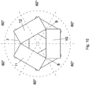
- the angular arrangement between the roll units results in having a plurality of rolls, between inlet and outlet of the soft reduction device, which in a front view along the feed direction of the metal product, are radially arranged with respect to the center of the product itself, for example, with angles of 60° from one another, as shown in Figure 10 .
- a further advantage of the present invention is the possibility of adjusting the position of the rolls of each soft reduction units to adapt the device to the processing of metal products of various diameters.
- each soft reduction unit may be provided with adjustment means for adjusting the position of at least two rolls of the three rolls, which adjustment means are configured to adjust the position of the rolls with respect to the center of the metal product to be pressed, that is with respect to the advancement axis of the metal product to be pressed, while keeping the centerline planes of the three rolls, which are perpendicular to the respective rotation axes of said three rolls, at 120° from one another in any working position. Therefore, the three rolls always apply equal radial pressing forces at 120° from one another, directed towards the center of the metal product, during the passage of the metal product in a zone delimited by the three rolls, and the resultant vector of said radial pressing forces is equal to zero.
- the soft reduction units 2 and/or 2' comprise an upper roll 7 having a horizontal rotation axis and arranged above two lower rolls 8, 9 having a rotation axis inclined with respect to the horizontal, while the subsequent and adjacent second soft reduction units 3 and/or 3' comprise a lower roll 10 having a horizontal rotation axis and arranged fixedly below two upper rolls 11, 12 having a rotation axis inclined with respect to the horizontal, or vice versa.
- the configuration of the rolls of the soft reduction unit in Figure 3 can be defined as a Y shaped configuration and the configuration of the rolls of the soft reduction unit in Figure 2 can be defined as an upside-down Y configuration or as a A (lambda) configuration, considering the arrangement of the centerline planes of the rolls, which are orthogonal to the respective rotation axes.
- At least one roll of said three rolls is motorized in each soft reduction unit.
- only roll 7, 10 having a horizontal rotation axis is motorized.
- the upper roll 7 is connected to a shaft 13, optionally to an extension, which may be actuated by motor 14, while the lower roll 10 in Figure 3 is connected to a shaft 15, optionally to an extension, which may be actuated by motor 16.
- only two rolls or all three rolls are motorized. This motorization of at least one roll allows to avoid the use of extraction units upstream of the soft reduction device for extracting the product from the casting curve.
- the position adjustment means are adapted to adjust the position of all three rolls 7, 8, 9; while in the soft reduction unit 3 shown in Figure 3 , the position adjustment means are adapted to adjust only the position of the two upper rolls 11, 12.
- the adjustment means in the soft reduction unit 2 comprise:
- Said first translation means comprise for example, a first cylinder 17 having vertical axis when the roll 7 has horizontal rotation axis and the soft reduction unit 2 is arranged with the longitudinal axis W thereof vertical
- said second translation means comprise at least one second cylinder 18 for each lower roll 8, 9, adapted to linearly move the respective lower roll along a respective fixed guide 19, or fixed sliding block, which fixed guide is inclined according to the respective plane X, Z.
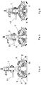
- Figures from 4 to 6 show three positions taken on by the three rolls 7, 8, 9 to adapt to the diameter of the metal product on which the soft reduction is to be performed.
- sensors for detecting the angular position of the rolls 7, 8, 9 from one another, and/or synchronization means for synchronizing the actuation of the first cylinder 17 and of the second cylinders 18.
- the adjustment means in the soft reduction unit 3 ( Figure 3 ) comprise:
- the centerline plane V is a vertical plane when roll 10 has horizontal rotation axis.
- said actuating means is a cylinder 21, for example a hydraulic cylinder, having vertical axis when roll 10 has horizontal rotation axis and the soft reduction unit 3 is arranged with the longitudinal axis thereof vertical.
- Figures from 7 to 9 show three positions taken on by the upper rolls 11, 12 to adapt to the diameter of the metal product on which the soft reduction is to be performed, the lower roll 10 being in fixed position.
- the symmetrical lever mechanism 20 may comprise, for example:
- Each joint 25 therefore connects a first lever 23 to the respective second lever 27.
- Each roll-holder device 29 supports one of the two upper rolls 11, 12 of the soft reduction unit 3, which are arranged at 120° from one another and with respect to the lower roll 10, and is configured to slide along a respective inclined plane X', Z'.
- the two inclined planes X', Z' are convergent and symmetrical with respect to plane V.
- the roll-holder device 29 When the roll-holder device 29 slides, it linearly moves the respective upper roll 11, 12 along a related fixed guide, or fixed sliding block, which is inclined according to the respective plane X', Z'.
- the planes X', Z' form an angle of 30° with respect to plane V.
- the upper rolls 11, 12 have centerline planes, which are orthogonal to the respective rotation axes, inclined by an angle other than zero with respect to the planes X', Z' and arranged at 120° from the centerline plane of the fixed lower roll 10, coinciding with the vertical plane V in the case roll 10 has a horizontal rotation axis.
- Cylinder 21 which controls the movement and adjusts the pressing of the upper rolls 11, 12, presses on the pressure element 30 which slides downwards along plane V.
- the downwards movement of the pins 28 causes a downwards movement of the roll-holder devices 29.
- the alignment of the pins 28 with the pins 24 and the pins 31 allows a transmission of a linear force which causes the roll-holder devices 29 to slide on the respective sliding blocks or fixed guides, thus linearly moving downwards the rolls 11, 12 along the inclined planes X', Z'.
- sensors for detecting the angular position of the rolls 10, 11, 12 between one another.
- the adjustment means in the soft reduction unit 3 may instead comprise two actuating means, for example two cylinders, arranged symmetrically with respect to plane V and adapted to cause the roll-holder devices 29 to slide on the respective sliding blocks or fixed guides, thus linearly moving downwards the upper rolls 11, 12 along the inclined planes X'. Z'.
- a further advantage of the present invention lies in the fact that the above-described adjustment means of the position of the rolls may be used to cause the extrados of the cast metal product to coincide with the pass-line of the processing line downstream of the casting curve.
- the lower rolls 8, 9 and 10 of the at least two soft reduction units 2, 3 are positioned so that the extrados of the casting curve 5 upstream coincides with the pass-line of the processing line 6 downstream ( Figure 1 ).
- the fixed lower roll 10 of the soft reduction units 3, 3' i.e. those with configuration of the soft reduction rolls having Y shape
- the position of the two lower rolls 8, 9 of the soft reduction units 2, 2' i.e. those with configuration of the soft reduction rolls having upside-down Y or A shape, may be adjusted, by means of the aforesaid adjustment means, so that the extrados of the advancing metal product coincides with the pass-line of the processing line 6.
- the adjustment of the position of the lower rolls 8, 9 may be performed for example, due to the automation of the plant, which through measuring devices installed along the casting line and on the soft reduction device itself, may measure the cast section and calculate the correct height at which to set said lower rolls, so as to cause the pass-line to coincide with the extrados of the product, thus achieving the reduction treatment adequate for the thermal model set for the type of product processed.
- the pressing pressures of the various units forming the soft reduction device may also be set through automation, thus achieving the so-called dynamic soft reduction. Thereby, the liquid core of the product will certainly be pressed in an optimal manner, while simultaneously keeping it in a final shape as close as possible to the round shape.
- a continuous production process of round-section metal products comprises:
- said three rolls apply equal radial pressing forces at 120° from one another, directed towards the center of the metal product, and the resultant vector of said radial pressing forces is equal to zero.
Landscapes
- Engineering & Computer Science (AREA)
- Mechanical Engineering (AREA)
- Continuous Casting (AREA)
- Press Drives And Press Lines (AREA)
- Forging (AREA)
Description
- The present invention relates to a soft reduction device for round-section blumes or billets having liquid or partially liquid core, coming from a continuous casting machine, in order to compress the product in a controlled manner, thus reducing the liquid section and improving the inner quality thereof.
- Various devices and methods for pressing a liquid-core cast product are known from the prior art, and this operation is called "soft reduction".
- This technology is particularly common within the area of slabs, which are characterized by being much wider than they are thick.
- The skin of the product begins forming in the crystallizer due to the progressive cooling to which the product is subjected. As the product travels downstream dragged by the straightening units, it is subjected to continuous direct and indirect cooling operations and this results in an increase of the thickness of the skin, resulting from the subtraction of heat from the core of the product performed by the cooling system.
- The product is cast from the tundish into the crystallizer and starts its descent towards the extraction area downstream, being cooled and contained by the containment rolls. The thickness of the product skin increases as the product descends and cools off, until there is the spontaneous joining of the skin in the so-called "metallurgical cone", at which point the complete solidification of the product is achieved.
- The process for forming the skin generally is influenced by various parameters, in particular by the steel grade of the cast product, by the heat exchange undergone by the cast product during casting, by the casting speed and by the dimensions of the product itself.
- It is necessary that the complete solidification of the product occurs so as to preserve the inner quality thereof: indeed, as the product solidifies, there is a decrease of the volume occupied by the liquid fraction which initially occupies a larger volume with respect to the solid fraction. This volumetric difference does not affect the product very much in the first part of the casting curve, since the liquid fraction volume lost during solidification is replaced by the liquid further upstream pushed downstream by the ferrostatic pressure. However, in proximity of the vertex of the metallurgical cone, the solid component and the liquid component are no longer well distinguished from each other, thus causing the so-called "mushy zone".
- From a microscopic point of view, the appearance of the skin of the product in contact with the liquid core has a series of crystalline branches called dendrites, which when the skin is about to be joined, tend to intersect with one another, thus forming a barrier for the inlet of the liquid above, preventing filling with new liquid in the areas subjected to a decrease of the volume of liquid fraction due to the solidification, and causing the formation of undesired porosity in the inner structure of the product.
- A further problem generated in this solidification step is that of macro segregations: as the product solidifies, the dendrites extend and tend to bring the alloy elements (e.g. carbon, sulfur, etc.) towards the liquid core of the product. This phenomenon causes a difference in the chemical composition along the section of the product. These migrations of alloy elements cause undesired differences of the mechanical properties, thermal properties, etc. between the various areas of the product, while a product having uniform structure and properties is instead desirable.
- In order to obviate these drawbacks, the soft reduction treatment was developed, which provides the controlled pressing of the cast metal products, e.g. slabs or blumes or billets, wherein the cast metal product is subjected to an action of reducing the thickness while the core is still liquid or partially liquid in an area downstream of the ingot-mold, thus obtaining a less thick product with respect to the cast one at the outlet of the continuous casting machine.
- The main advantage of reducing the thickness of the liquid or partially liquid core is to obtain an improvement of the solidification structure together with an improved inner quality of the cast product.
- In order to be effective, the soft reduction should occur with a continuous and controlled reduction of the thickness of the cast product up to when it contains therein a liquid or partially liquid core, which may be obtained with a substantially conical reduction profile of the stretch of cast product involved.
- The most common soft reduction devices provide pressing the product by means of pairs of opposite rolls: the pressing force here is therefore applied with equal intensity and opposite direction, thus causing a decrease of the thickness of the product and an extension thereof (called "bulging").
- This soft reduction treatment is commonly used in the field of continuous slab casting since the widening of the side faces is not such as to seriously affect the finished product which, once the curved sides have been conveniently trimmed, will be ready for rolling or other successive operations.
- With regards instead to products having rectangular or square section, the soft reduction is to be performed more carefully, since an excessive curving would cause an excessive deformation of the products which would then be difficult to process.
- This problem is felt even more for round-section products since keeping the shape is essential for processing and selling the product on the market: indeed, by using only two rolls which press the product in opposite directions to close the liquid core thereof, there is a risk of excessive oval deformation of the section of the product. In an attempt to correct this ovalization, another deformation may be generated, made with rolls shaped so as to obtain a round section with a smaller section. However, this further deformation, which requires at least two passes, does not always decrease the section of the product and at the same time keep it perfectly round. Indeed, further forming passes are often required downstream for the further definition of the round geometry.
- A partial solution to this problem provides eliminating the first pressing step by directly casting an elliptical-section product which in the next soft reduction step is deformed into a round shape by two parallel shaped rolls.
- However, the deformation operation to pass from the elliptical section to the round section - in particular, the more the ellipse is pressed - results in tensions in the core of the product which may damage the inner quality thereof.
- Thus, the need is felt to provide a soft reduction device for round-section cast products which allows to overcome the aforesaid drawbacks.
- It is an object of the present invention to provide a soft reduction device for round-section cast metal products, such as blumes or billets, which allows a controlled and effective closing of the liquid cone, thus reducing the section of product with respect to the initial casting one, and at the same time allows maintaining substantially a rounded shape, which already is acceptable for processing and selling the product when it is outlet from said device.
- Advantageously, the soft reduction device of the invention is designed for carrying out the soft reduction of casting products, made of metal, having a round section, said round section being maintained round sectioned through the whole soft reduction process. Therefore the terminology "round section product" refers both to the casting product, having a liquid or partially liquid core, and to the final product of soft reduction, that is completely solidified.
- It is another object of the invention to provide a soft reduction device capable of obtaining completely solidified round section products having a substantially uniform chemical composition along the whole section of the product, and therefore uniform properties.
- It is another object of the invention to provide a soft reduction device capable of limiting the formation of voids due to the shrinking from cooling of the product volume.
- Thus, the present invention achieves the above objects by providing a soft reduction device of round-section metal products having liquid or partially liquid core for reducing the thickness of said metal product coming from a continuous casting machine, which according to
claim 1 comprises at least two soft reduction units,
wherein said at least two soft reduction units are arranged in series,
wherein each soft reduction unit is provided with a group of only three rolls arranged at 120° from one another,
and wherein the group of three rolls of one soft reduction unit is offset by a predetermined angle with respect to the group of three rolls of an adjacent soft reduction unit. - The three rolls of each soft reduction unit interfere with the advancing metal product so as to reduce the section thereof, thus closing the liquid core, by acting at 120° angles from one another so that the resulting vector of the radial pressing forces applied on the product is equal to zero.
- By providing pressing forces of equal intensity from three equidistant directions, the closing of the liquid core is more effective since the deformation is less abrupt with respect to the solutions with only two pressing rolls. Indeed, by using only three rolls in each soft reduction unit, the outer surface of the round-section products is wound in an optimal manner. Such a winding causes a good propagation of the pressing forces towards the core of the product since the latter does not have very much space to deform outwards, considering the vicinity between the rolls. Therefore, the material will tend to move mainly towards the center of the product, filling the areas occupied by the liquid core which in turn is forced to retract, or in the case of the mushy zone, to solidify.
- This operation results in the forced inner union of the skin, and therefore in the closing of the kissing point obtained through the interpenetration and solidification of the dendrites. Thus, the creation of voids due to the shrinking from cooling of the product volume is also avoided, since the inner space is forcibly filled with solidified material, pushed by the deformation actuated by the soft reduction rolls. Advantageously, to better keep the rounded shape, several soft reduction units are arranged in series, over which the radial pressing forces are divided, which are therefore applied to a lesser extent by the rolls of the units after the first one. Advantageously, according to the invention, the number of soft reduction units may vary. In particular, there may be provided from three to eight soft reduction units arranged in series, preferably four soft reduction units arranged in series. It has been noted that providing a number of soft reduction units greater than eight induces a temperature dispersion which does not allow an optimal processing of the material.
- To maximize keeping the rounded shape, the arrangement of the rolls advantageously is offset between one soft reduction unit and the next, so that the pressed areas of the product vary from one unit to the other and therefore, the rounded shape is preserved better.
- In a first advantageous variant, there are provided two soft reduction units arranged in series, with groups of three offset rolls, i.e. rotated by 180° from one another. This arrangement results in having six rolls, between inlet and outlet of the soft reduction device, which in a front view along the feed direction of the cast round product, are radially arranged with respect to the center of the cast round product, with angles of 60° from one another.
- Other variants of the invention may provide further offsetting the groups of rolls of the soft reduction units. For example, there may be provided three soft reduction units with three rolls, therefore with nine rolls in total, arranged so as to obtain, in a front view along the feed direction of the cast round product, an offset of 30° between one roll and the next. Another example instead provides five soft reduction units with three rolls, therefore with fifteen rolls in total, arranged so as to obtain, in a front view along the feed direction of the cast round product, an offset of 15° between one roll and the next, and so on. The more soft reduction units forming the device, the less the contribution of radial pressing force of the rolls required to close the liquid cone since each of them contributes to a partial reduction, thus limiting the excessive deforming effect generated with the solutions of the prior art with only two rolls.
- In a further advantageous variant, since it may be complex and costly to provide an increased number of soft reduction units in series while simultaneously offsetting the rolls along many incident axes, there is instead provided the arrangement of a plurality of soft reduction units, preferably four or six or a maximum of eight, arranged in series and with groups of three rolls offset by 180° adjacent from one another. This arrangement results in having twelve or eighteen or twenty-four rolls, between inlet and outlet of the soft reduction device, which in a front view along the feed direction of the cast round product, are radially arranged with respect to the center of the cast round product, with angles of 60° from one another. Thereby, by alternating the axes of the rolls with a sequence of the type Y-λ or λ-Y, it is sufficient to design and construct only two separate types of soft reduction units.
- Advantageously, in a preferred variant, in addition to closing the liquid core, the soft reduction units of the device of the invention are also capable of extracting the product from the casting line by performing a function similar to that of the extraction and straightening units which are commonly used in continuous casting machines. In this variant, at least one of the rolls of each soft reduction unit is motorized. This solution allows to avoid the installation, upstream of the soft reduction device, of an extraction unit which should grasp, or grip, intrados and extrados of the product and drag it downstream in the first soft reduction unit and straighten it at the same time.
- A further advantage of the present invention is the possibility of providing position adjustment means for adjusting the position of the rolls, so that the same soft reduction unit can process products having various diameters. For example, the rolls may be mutually moved close or away by means of hydraulic actuators, lever or pantograph mechanisms, or others.
- Moreover, the movement of the rolls may be performed linearly along guides, sliding blocks or similar elements, or performed by means of curvilinear movements or a combination of linear and curvilinear movements.
- The soft reduction rolls may also have various shapes in the stretch in contact with the outer surface of the cast product: they may for example, have a flat panel shape or be shaped and joined with angles adequate to the diameter of the product to be processed.
- A further feature of the present solution is the possibility of causing the extrados of the cast product to coincide with the pass-line of the line downstream of the casting curve. Indeed, since the casting line in which the soft reduction units of the present invention will be installed is to cast various diameters of product, there is a need to vary certain geometries of the casting curve, in particular the arrangement of the containment rolls and of the cooling means, by adapting them to those of each cast product. Normally, the assembly of radii on which a casting line is designed is calculated according to the extrados of a product; then the minimum and maximum ranges corresponding to the minimum and maximum intrados of the range of products to be cast, is calculated.
- Should the extrados radius vary, there would be problems in aligning the casting line and the utility units downstream (e.g. cooling plates, roller tables, etc.) for each product. Instead, by causing the extrados to coincide with the pass-line, corresponding for example to the cooling plate, such a problem does not exist since the casting curve and cooling plate are always aligned. This advantage results in these soft reduction units also being installable on existing casting lines, since the extension thereof is strictly vertical and they ensure the continuous alignment between cast and utilities downstream.
- The dependent claims describe preferred embodiments of the invention.
- Further features and advantages of the invention will be more apparent in light of the detailed description of preferred, but not exclusive, embodiments of a soft reduction device, disclosed by way of a non-limiting example, with the aid of the accompanying drawings in which:
-
Fig. 1 depicts a diagram of a casting line comprising a soft reduction device according to the invention; -
Fig. 2 depicts a side view of a first embodiment of a soft reduction unit of the device of the invention; -
Fig. 3 depicts a side view of a second embodiment of a soft reduction unit of the device of the invention; -
Fig. 4 depicts a side view of part ofFig. 2 , in a first operating position; -
Fig. 5 depicts a side view of the part ofFig 4 , in a second operating position; -
Fig. 6 depicts a side view of the part ofFig 4 , in a third operating position; -
Fig. 7 depicts a side view of part ofFig. 3 , in a first operating position; -
Fig. 8 depicts a side view of the part ofFig 7 , in a second operating position; -
Fig. 9 depicts a side view of the part ofFig 7 , in a third operating position; -
Fig. 10 depicts a diagrammatic front view of the rolls of the soft reduction unit, in a preferred variant. - The same reference numerals in the drawings identify the same elements or components.
- With reference to the figures, there is depicted a preferred embodiment of a soft reduction device according to the invention, indicated by 1 as a whole.
- Such a soft reduction device is designed to perform a soft reduction of a round-section metal product, having liquid or partially liquid core, i.e. for reducing the thickness of a round-section cast metal product coming from a continuous casting machine. Therefore, each soft reduction unit of the device is substantially different from the guide units with adjustable rolls that guide the cast product simply accompanying the metal product during its advancement without reducing the thickness thereof and, notably, without obtaining a controlled and effective closing of the liquid cone. Moreover, as known to the skilled person, a soft reduction device and a soft reduction unit are well distinguished from a rolling device and a rolling unit, respectively, not only by the functional point of view but also by the constructional point of view. Indeed, the rolling devices or units - unlike the soft reduction devices or units - are designed to reduce the thickness of a completely solidified metal product (thus without liquid core). The rolling devices or units are provided with backup rolls, while the soft reduction devices or units are not. The backup rolls are present in the rolling devices or units to provide a robust support for the working rolls, thus helping to ensure a proper performance of the entire rolling mill. Also, the forces acting on the metal product in a rolling device are different from the forces acting on the metal product in a soft reduction device, given the difference in the consistency between a completely solidified product and a casting product. The several constructional differences between soft reduction devices and rolling devices are also reflected in their cost, the latter costing at least twice as much as the soft reduction devices.
-
Figure 1 shows part of a plant for a continuous production of round-section metal products comprising: - a continuous casting machine provided with at least one round-
section crystallizer 4 and arespective casting curve 5; - a
soft reduction device 1 arranged near the end of therespective casting curve 5, - and a
processing line 6 of the round-section metal product, arranged downstream of thesoft reduction device 1. - The
soft reduction device 1 comprises at least twosoft reduction units - Advantageously, each
soft reduction unit - In the variant in
Figure 1 , there are provided foursoft reduction units numerals 2, 2' have an equal angular arrangement of the three rolls, offset by 180° with respect to the equal angular arrangement of the three rolls of the soft reduction units indicated bynumerals 3, 3'. - In the example in
Figure 1 , at least the first soft reduction units of the device of the invention are positioned along the end part of thecasting curve 5 and act also as extraction and straightening units. - In another example (not shown), all the soft reduction units are arranged parallel to one another along a completely rectilinear stretch of plant, i.e. completely after the
casting curve 5. Here, there are provided specific extraction and straightening units upstream of the device of the invention. - In another variant of the invention, there instead are provided only two soft reduction units and the group of three rolls of the first soft reduction unit is offset by 180° with respect to the group of three rolls of the second soft reduction unit, which is subsequent and adjacent to the first soft reduction unit.
- Other variants may include, for example, the use of four, six or eight soft reduction units, with the group of three rolls of a soft reduction unit offset by 180° with respect to the group of three rolls of the subsequent and adjacent soft reduction unit.
- In all these variants, the angular arrangement between the roll units results in having a plurality of rolls, between inlet and outlet of the soft reduction device, which in a front view along the feed direction of the metal product, are radially arranged with respect to the center of the product itself, for example, with angles of 60° from one another, as shown in
Figure 10 . - The more soft reduction units forming the device, the less the contribution of radial pressing force which each soft reduction unit should ensure to close the liquid cone, since each of them contributes to a partial reduction of the thickness of the metal product.
- A further advantage of the present invention is the possibility of adjusting the position of the rolls of each soft reduction units to adapt the device to the processing of metal products of various diameters.
- Advantageously, each soft reduction unit may be provided with adjustment means for adjusting the position of at least two rolls of the three rolls, which adjustment means are configured to adjust the position of the rolls with respect to the center of the metal product to be pressed, that is with respect to the advancement axis of the metal product to be pressed, while keeping the centerline planes of the three rolls, which are perpendicular to the respective rotation axes of said three rolls, at 120° from one another in any working position. Therefore, the three rolls always apply equal radial pressing forces at 120° from one another, directed towards the center of the metal product, during the passage of the metal product in a zone delimited by the three rolls, and the resultant vector of said radial pressing forces is equal to zero.
- In a preferred embodiment shown in
Figures 2 and3 , thesoft reduction units 2 and/or 2' comprise anupper roll 7 having a horizontal rotation axis and arranged above twolower rolls soft reduction units 3 and/or 3' comprise alower roll 10 having a horizontal rotation axis and arranged fixedly below twoupper rolls Figure 3 can be defined as a Y shaped configuration and the configuration of the rolls of the soft reduction unit inFigure 2 can be defined as an upside-down Y configuration or as a A (lambda) configuration, considering the arrangement of the centerline planes of the rolls, which are orthogonal to the respective rotation axes. To improve the extraction and straightening function, it is preferable to provide, along the feed direction of the product, a soft reduction unit having a A (lambda) configuration (like that shown inFigure 2 ) as first soft reduction unit. - However, there it is not necessary for the
roll 7 of thesoft reduction units 2 and/or 2' and for theroll 10 of thesoft reduction units 3 and/or 3' to have a horizontal rotation axis.Such rolls - Preferably, at least one roll of said three rolls is motorized in each soft reduction unit. In a preferred variant, only roll 7, 10 having a horizontal rotation axis is motorized. For example, in
Figure 2 , theupper roll 7 is connected to ashaft 13, optionally to an extension, which may be actuated bymotor 14, while thelower roll 10 inFigure 3 is connected to ashaft 15, optionally to an extension, which may be actuated bymotor 16. - In other variants, only two rolls or all three rolls are motorized. This motorization of at least one roll allows to avoid the use of extraction units upstream of the soft reduction device for extracting the product from the casting curve.
- In the
soft reduction unit 2 shown inFigure 2 , the position adjustment means are adapted to adjust the position of all threerolls soft reduction unit 3 shown inFigure 3 , the position adjustment means are adapted to adjust only the position of the twoupper rolls - The adjustment means in the
soft reduction unit 2 comprise: - first translation means, adapted to translate the
upper roll 7 along a centerline plane thereof which is orthogonal to the rotation axis thereof, for example adapted to translate vertically in the case of horizontal rotation axis ofroll 7 andsoft reduction unit 2 arranged with the longitudinal axis W thereof vertical, - and second translation means adapted to translate the two
lower rolls upper roll 7, along respective inclined planes X, Z. The two inclined planes X, Z are convergent and symmetrical with respect to the centerline plane of theupper roll 7. In a preferred variant, the inclined planes X, Z form an angle of 30° with respect to the horizontal. The lower rolls 8, 9 have centerline planes, which are orthogonal to the respective rotation axes, inclined by an angle other than zero with respect to the planes X, Z and arranged at 120° from the centerline plane of theupper roll 7, thus coinciding with a vertical plane in the case the upper roll has a horizontal rotation axis. - Said first translation means comprise for example, a
first cylinder 17 having vertical axis when theroll 7 has horizontal rotation axis and thesoft reduction unit 2 is arranged with the longitudinal axis W thereof vertical, and said second translation means comprise at least onesecond cylinder 18 for eachlower roll guide 19, or fixed sliding block, which fixed guide is inclined according to the respective plane X, Z. In one variant, there are provided for example, twocylinders 18 for eachlower roll - Figures from 4 to 6 show three positions taken on by the three
rolls rolls first cylinder 17 and of thesecond cylinders 18. - In a preferred variant, the adjustment means in the soft reduction unit 3 (
Figure 3 ) comprise: - a
symmetrical lever mechanism 20 connected in a mirror-like manner to the twoupper rolls lower roll 10 orthogonal to the rotation axis of thelower roll 10 itself, - and an actuating means of said
symmetrical lever mechanism 20. - The centerline plane V is a vertical plane when
roll 10 has horizontal rotation axis. For example, said actuating means is acylinder 21, for example a hydraulic cylinder, having vertical axis whenroll 10 has horizontal rotation axis and thesoft reduction unit 3 is arranged with the longitudinal axis thereof vertical. - Figures from 7 to 9 show three positions taken on by the upper rolls 11, 12 to adapt to the diameter of the metal product on which the soft reduction is to be performed, the
lower roll 10 being in fixed position. - The
symmetrical lever mechanism 20 may comprise, for example: - a movable element or
pressure element 30, which slides along plane V, on whichcylinder 21 acts; - two
first levers 23, which are symmetrical with respect to plane V, hinged at a first end of thepressure element 30 by means of arespective pin 22; - two
joints 25, which are symmetrical with respect to plane V, for example in the shape of a substantially triangular plate, having a first vertex hinged to a second end of a respectivefirst lever 23 by means of arespective pin 24, and a second vertex hinged by means of a respective fixedpin 26 to the structure of the soft reduction unit; - two
second levers 27, which are symmetrical with respect to plane V, hinged at a first end thereof by means of arespective pin 28 to the third vertex of the respective joint 25, and hinged at a second end thereof by means of arespective pin 31 to a respective roll-holder device 29. - Each joint 25 therefore connects a
first lever 23 to the respectivesecond lever 27. Each roll-holder device 29 supports one of the twoupper rolls soft reduction unit 3, which are arranged at 120° from one another and with respect to thelower roll 10, and is configured to slide along a respective inclined plane X', Z'. The two inclined planes X', Z' are convergent and symmetrical with respect to plane V. - When the roll-
holder device 29 slides, it linearly moves the respectiveupper roll - In a preferred variant, the planes X', Z' form an angle of 30° with respect to plane V.
- The upper rolls 11, 12 have centerline planes, which are orthogonal to the respective rotation axes, inclined by an angle other than zero with respect to the planes X', Z' and arranged at 120° from the centerline plane of the fixed
lower roll 10, coinciding with the vertical plane V in thecase roll 10 has a horizontal rotation axis. - With reference to
Figures 3 and7 to 9 , below is described the sequence of movements of theaforesaid mechanism 20. -
Cylinder 21, which controls the movement and adjusts the pressing of theupper rolls pressure element 30 which slides downwards along plane V. - As shown in the passage from
Figure 7 to Figure 8 , thepins 22, which are integral with thepressure element 30, slide downwards, thus lowering thefirst levers 23 which second ends simultaneously widen outwards (see position of thepins 24 inFigure 8 ). - This movement of the
first levers 23 causes a rotation of thejoints 25 about the fixed pins 26, which causes a downwards push of thepins 28, and therefore of thesecond levers 27. In the configuration inFigure 8 , thepins 28 are aligned with therespective pins 24 of thefirst levers 23 and with thepins 31 of the respective roll-holder devices 29. - The downwards movement of the
pins 28 causes a downwards movement of the roll-holder devices 29. In particular, the alignment of thepins 28 with thepins 24 and thepins 31 allows a transmission of a linear force which causes the roll-holder devices 29 to slide on the respective sliding blocks or fixed guides, thus linearly moving downwards therolls - As shown in the passage from
Figure 8 to Figure 9 , the maximum pressure ofcylinder 21 results in a further rotation of thejoints 25 about the fixed pins 26 and the simultaneous maximum lowering of the roll-holder devices 29, with associatedrolls Figure 3 ). - There may be provided sensors for detecting the angular position of the
rolls - In an alternative variant (not shown), the adjustment means in the soft reduction unit 3 (
Figure 3 ) may instead comprise two actuating means, for example two cylinders, arranged symmetrically with respect to plane V and adapted to cause the roll-holder devices 29 to slide on the respective sliding blocks or fixed guides, thus linearly moving downwards the upper rolls 11, 12 along the inclined planes X'. Z'. In this variant, there may be provided sensors for detecting the angular position of therolls - A further advantage of the present invention lies in the fact that the above-described adjustment means of the position of the rolls may be used to cause the extrados of the cast metal product to coincide with the pass-line of the processing line downstream of the casting curve.
- Advantageously, the
lower rolls soft reduction units casting curve 5 upstream coincides with the pass-line of theprocessing line 6 downstream (Figure 1 ). - In particular, the fixed
lower roll 10 of thesoft reduction units 3, 3', i.e. those with configuration of the soft reduction rolls having Y shape, is arranged so as to cause the resting surface thereof for the advancing metal product to coincide with the pass-line of theprocessing line 6; while the position of the twolower rolls soft reduction units 2, 2', i.e. those with configuration of the soft reduction rolls having upside-down Y or A shape, may be adjusted, by means of the aforesaid adjustment means, so that the extrados of the advancing metal product coincides with the pass-line of theprocessing line 6. - The adjustment of the position of the
lower rolls - Therefore, a continuous production process of round-section metal products according to the invention comprises:
- continuously casting a round-section metal product by means of a continuous casting machine provided with at least one round-
section crystallizer 4 and arespective casting curve 5; - carrying out a soft reduction of said round-section metal product, while keeping the round section through the whole soft reduction operation by means of the
soft reduction device 1 arranged near the end of therespective casting curve 5; - processing the round-section metal product exiting from said
soft reduction device 1 by means of theprocessing line 6. - Advantageously, during the soft reduction, there may be provided an adjustment of the position of at least two rolls of the three rolls of the soft reduction unit with respect to the center of the metal product to be pressed so as to keep the centerline planes of the three rolls, which are perpendicular to the respective rotation axes of said three rolls, at 120° from one another in any working position, adapting the soft reduction units to the diameter of the metal product which passes in the area delimited by the respective three rolls. Thereby, said three rolls apply equal radial pressing forces at 120° from one another, directed towards the center of the metal product, and the resultant vector of said radial pressing forces is equal to zero.
Claims (16)
- A soft reduction device (1) of a casting product made of metal with a round-section having liquid or partially liquid core, for reducing the thickness of said casting product, coming from a continuous casting machine, while maintaining the round section, the device comprising at least two soft reduction units (2, 3), wherein said at least two soft reduction units (2, 3) are arranged in series, wherein each soft reduction unit (2, 3) is provided with a group of only three rolls arranged at 120° from one another,
and wherein the group of three rolls (7, 8, 9) of one soft reduction unit is offset by a predetermined angle with respect to the group of three rolls (10, 11, 12) of an adjacent soft reduction unit. - A device according to claim 1, wherein said predetermined angle is 180°.
- A device according to claim 1, wherein there are provided only two soft reduction units (2, 3) and the group of three rolls of a first soft reduction unit (2) is offset by 180° with respect to the group of three rolls of a second soft reduction unit (3), which is subsequent and adjacent to the first soft reduction unit (2).
- A device according to claim 1 or 2, wherein there are provided from three to eight soft reduction units.
- A device according to claim 1, wherein there are provided four soft reduction units (2, 3, 2', 3') and the group of three rolls of a soft reduction unit (2, 2') is offset by 180° with respect to the group of three rolls of the subsequent and adjacent soft reduction unit (3, 3').
- A device according to any one of the preceding claims, wherein each soft reduction unit is provided with position adjustment means for adjusting the position of at least two rolls of said three rolls, adapted to adjust the position of the rolls with respect to the center of the metal product to be pressed keeping the centerline planes of the three rolls, which are perpendicular to the respective rotation axes of said three rolls, at 120° from one another in any working position.
- A device according to any one of the preceding claims, wherein a first soft reduction unit (2) comprises an upper roll (7) having a respective rotation axis, preferably horizontal, and arranged above two lower rolls (8, 9) having a rotation axis inclined by a 60° angle with respect to the rotation axis of the upper roll, while the subsequent and adjacent second soft reduction unit (3) comprises a lower roll (10) having a respective rotation axis, preferably horizontal, and arranged fixedly below two upper rolls (11, 12) having a rotation axis inclined by a 60° angle with respect to the rotation axis of the lower roll, or vice versa.
- A device according to any one of the preceding claims, wherein at least one roll of said three rolls is motorized in each soft reduction unit.
- A device according to claim 7 or 8, wherein in said first soft reduction unit (2) the position adjustment means are adapted to adjust the position of all three rolls (7, 8, 9), while in said second soft reduction unit (3) the position adjustment means are adapted to adjust only the position of the two upper rolls (11, 12).
- A device according to claim 9, wherein the position adjustment means of said first soft reduction unit (2) comprise first translation means, adapted to translate the upper roll (7) along a centerline plane thereof which is perpendicular to the respective rotation axis, and second translation means adapted to translate the two lower rolls (8, 9) along respective inclined planes (X, Z), the two inclined planes (X, Z) being convergent and symmetrical with respect to the centerline plane of the upper roll (7).
- A device according to claim 10, wherein said first translation means comprise a first cylinder (17), and said second translation means comprise at least one second cylinder (18) for each lower roll (8, 9), adapted to linearly move the respective lower roll along a fixed guide.
- A device according to claim 9 or 10, wherein the position adjustment means of said second soft reduction unit (3) comprise- a symmetrical lever mechanism (20) symmetrically connected to the two upper rolls (11, 12), the levers being symmetrical with respect to a centerline plane of the lower roll (10) orthogonal to the rotation axis of said lower roll,- and an actuating means of said symmetrical lever mechanism (20),said symmetrical lever mechanism (20) being configured to translate the two upper rolls (11, 12) along respective inclined planes (X', Z'), the two inclined planes (X', Z') being convergent and symmetrical with respect to said centerline plane of the lower roll (10).
- A device according to claim 12, wherein said actuating means is a cylinder (21).
- A device according to claim 9 or 10, wherein the position adjustment means in said second soft reduction unit (3) comprise two actuating means, arranged symmetrically with respect to a center plane of the lower roll (10) orthogonal to the rotation axis of said lower roll, said actuating means being adapted to move the upper rolls (11, 12) linearly along respective inclined planes (X', Z'), the two inclined planes (X', Z') being convergent and symmetrical with respect to said center plane of the lower roll (10).
- A plant for a continuous production of round-section metal products comprising a continuous casting machine provided with at least one round-section crystallizer (4) and a respective casting curve (5);
a soft reduction device (1) according to claim 1 arranged near the end of the respective casting curve (5),
a processing line (6) of the round-section metal product exiting from said soft reduction device (1),
wherein lower rolls of the at least two soft reduction units are positioned so that the extradoss of the casting curve coincides with the pass-line of said processing line. - A continuous production process of round-section metal products, by means of a plant according to claim 15, comprising the following steps:- continuously casting a round-section metal product by means of a continuous casting machine provided with at least one round-section crystallizer (4) and a respective casting curve (5);- carrying out a soft reduction of said round-section metal product, while keeping the round section through the whole soft reduction operation by means of the soft reduction device (1) arranged near the end of the respective casting curve (5);- processing the round-section metal product exiting from said soft reduction device (1) by means of the processing line (6).
Applications Claiming Priority (2)
| Application Number | Priority Date | Filing Date | Title |
|---|---|---|---|
| IT102016000102472A IT201600102472A1 (en) | 2016-10-12 | 2016-10-12 | SOFT REDUCTION DEVICE FOR METAL PRODUCTS OF ROUND SECTION |
| PCT/IB2017/056300 WO2018069854A1 (en) | 2016-10-12 | 2017-10-12 | A device for the soft reduction of round-section metal products |
Publications (2)
| Publication Number | Publication Date |
|---|---|
| EP3525954A1 EP3525954A1 (en) | 2019-08-21 |
| EP3525954B1 true EP3525954B1 (en) | 2020-07-15 |
Family
ID=57960716
Family Applications (1)
| Application Number | Title | Priority Date | Filing Date |
|---|---|---|---|
| EP17795065.6A Active EP3525954B1 (en) | 2016-10-12 | 2017-10-12 | Device and method for the soft reduction of round-section metal products |
Country Status (8)
| Country | Link |
|---|---|
| US (1) | US10744559B2 (en) |
| EP (1) | EP3525954B1 (en) |
| JP (1) | JP6811315B2 (en) |
| CN (1) | CN109952166B (en) |
| ES (1) | ES2823303T3 (en) |
| IT (1) | IT201600102472A1 (en) |
| RU (1) | RU2710610C1 (en) |
| WO (1) | WO2018069854A1 (en) |
Families Citing this family (1)
| Publication number | Priority date | Publication date | Assignee | Title |
|---|---|---|---|---|
| AT523160B1 (en) | 2019-12-23 | 2021-06-15 | Gfm Gmbh | Process for processing a metallic cast strand with a round cross-section by reducing the cross-section in the final solidification area |
Family Cites Families (19)
| Publication number | Priority date | Publication date | Assignee | Title |
|---|---|---|---|---|
| AT244004B (en) * | 1961-12-29 | 1965-12-10 | Hufnagl Walter | Continuous caster |
| NL6809037A (en) * | 1967-06-28 | 1968-12-30 | ||
| US4294306A (en) * | 1979-09-14 | 1981-10-13 | Berenov Alexandr D | Withdrawal roll unit for horizontal continuous billet casting machines |
| DE3143244A1 (en) * | 1981-10-31 | 1983-05-11 | Kocks Technik Gmbh & Co, 4010 Hilden | Rolling stand for rolling bars or wire |
| JPS60118361A (en) * | 1983-11-30 | 1985-06-25 | Sumitomo Heavy Ind Ltd | Device for supporting and guiding round billet in continuous casting |
| JPH01289552A (en) * | 1988-05-16 | 1989-11-21 | Sumitomo Metal Ind Ltd | Forging press apparatus for round shaped continuously cast billet |
| EP0603330B1 (en) * | 1991-09-12 | 1996-04-03 | ARVEDI, Giovanni | A process and apparatus for the manufacture of billets and blooms from a continuously last steel showing high or excellent quality |
| JP3237518B2 (en) * | 1996-05-16 | 2001-12-10 | 日本鋼管株式会社 | Manufacturing method of chrome alloy steel round billet slab |
| IT1283801B1 (en) * | 1996-08-13 | 1998-04-30 | Innocenti Eng Spa | ROLLING MACHINE FOR THE CALIBRATION OF PIPES OR ASTIFORM BODIES IN GENERAL IN THE STEEL INDUSTRY |
| JPH10156495A (en) * | 1996-11-27 | 1998-06-16 | Sumitomo Metal Ind Ltd | Continuous casting method for billet slabs with round sections |
| JP3139402B2 (en) * | 1997-01-10 | 2001-02-26 | 住友金属工業株式会社 | Unsolidified rolling method of slab |
| DE19722980C1 (en) * | 1997-06-02 | 1998-06-04 | Aluhett Aluminium Halbzeugwerk | Roll sets for production of round wire |
| DE10144234A1 (en) * | 2001-09-08 | 2003-03-27 | Sms Demag Ag | Method and device for optimizing the quality of cast strands with round or approximately round cross sections |
| CN100352569C (en) * | 2005-12-22 | 2007-12-05 | 中冶集团北京冶金设备研究设计总院 | Single-driven input shaft draft-adjustable three-roll mill |
| DE102010034399A1 (en) * | 2010-08-14 | 2012-02-16 | Dieter Figge | Steel-continuous casting of large round- or square-cross sections, comprises oscillating vertical mold and subsequent secondary cooling and/or strand guide in form of arc-shaped or oval arch system consisting of segments |
| RU2498878C1 (en) * | 2012-04-24 | 2013-11-20 | Анатолий Аркадьевич Злобин | Method of making profiled iron from scrap metal and device to this end |
| CN102989774B (en) * | 2012-12-18 | 2015-01-21 | 中冶京诚工程技术有限公司 | Combined three-roller continuous rolling mill |
| JP5825456B2 (en) * | 2013-06-20 | 2015-12-02 | 新日鐵住金株式会社 | Continuous casting method for slabs |
| CN104308108A (en) * | 2014-08-15 | 2015-01-28 | 中冶连铸技术工程有限责任公司 | Straightening machine and method utilizing straightening machine reduce clamping deformation of big round billet |
-
2016
- 2016-10-12 IT IT102016000102472A patent/IT201600102472A1/en unknown
-
2017
- 2017-10-12 ES ES17795065T patent/ES2823303T3/en active Active
- 2017-10-12 RU RU2019111603A patent/RU2710610C1/en active
- 2017-10-12 CN CN201780063097.2A patent/CN109952166B/en active Active
- 2017-10-12 WO PCT/IB2017/056300 patent/WO2018069854A1/en not_active Ceased
- 2017-10-12 US US16/338,564 patent/US10744559B2/en active Active
- 2017-10-12 JP JP2019519305A patent/JP6811315B2/en not_active Expired - Fee Related
- 2017-10-12 EP EP17795065.6A patent/EP3525954B1/en active Active
Non-Patent Citations (1)
| Title |
|---|
| None * |
Also Published As
| Publication number | Publication date |
|---|---|
| US10744559B2 (en) | 2020-08-18 |
| IT201600102472A1 (en) | 2018-04-12 |
| CN109952166B (en) | 2021-12-07 |
| JP6811315B2 (en) | 2021-01-13 |
| ES2823303T3 (en) | 2021-05-06 |
| US20200038945A1 (en) | 2020-02-06 |
| JP2019530581A (en) | 2019-10-24 |
| WO2018069854A1 (en) | 2018-04-19 |
| RU2710610C1 (en) | 2019-12-30 |
| EP3525954A1 (en) | 2019-08-21 |
| CN109952166A (en) | 2019-06-28 |
Similar Documents
| Publication | Publication Date | Title |
|---|---|---|
| US5853043A (en) | Method and apparatus for continuous casting of a thin slab | |
| US3812900A (en) | Method of operating a multi-roll casting machine during and after freezing of the liquid core of the strand | |
| WO2020155264A1 (en) | Device and method for implementing core reduction technology in continuous casting round billet solidification process | |
| DE69615534T2 (en) | CONTINUOUS CASTING METHOD AND PLANT | |
| US4953615A (en) | Plant for the continuous casting of steel | |
| US10744559B2 (en) | Device for the soft reduction of round-section metal products | |
| US5803155A (en) | Casting line for slabs | |
| KR20130043116A (en) | Continuous casting device and relative method | |
| KR100819123B1 (en) | Method and apparatus for manufacturing foil slab | |
| JPH10193064A (en) | Unsolidified rolling method of slab | |
| US3766962A (en) | Method of continuously casting a slab | |
| EP3541548B1 (en) | Continuous casting device for thin slabs | |
| EP2697003B1 (en) | Feed roll assembly and method for operating a feed roll assembly | |
| WO2006056423A1 (en) | Continuous casting device and method | |
| EP0903192A1 (en) | Improvements in and relating to casting | |
| US4546816A (en) | Method and apparatus of continuously casting hollow round billets with a hypocycloidal mandrel and an inside rolling process | |
| CN211191919U (en) | Production equipment for producing large fillet or large chamfer continuous casting square billet/rectangular billet | |
| KR100907570B1 (en) | Vertical continuous casting method of steel band | |
| CN110944770B (en) | Continuous casting equipment and corresponding method | |
| EP0354764B1 (en) | Method of continuously casting strand of improved internal center segregation and center porosity | |
| JPH0366057B2 (en) | ||
| JPS601878Y2 (en) | Slab short side support device in continuous casting machine | |
| Han et al. | Ovality Defect Control for Round Casting based on Mechanical Deformation Analysis | |
| JP6295814B2 (en) | Light reduction device and continuous casting method for continuous casting apparatus | |
| JPWO1997014522A1 (en) | Continuous casting method and apparatus |
Legal Events
| Date | Code | Title | Description |
|---|---|---|---|
| STAA | Information on the status of an ep patent application or granted ep patent |
Free format text: STATUS: UNKNOWN |
|
| STAA | Information on the status of an ep patent application or granted ep patent |
Free format text: STATUS: THE INTERNATIONAL PUBLICATION HAS BEEN MADE |
|
| PUAI | Public reference made under article 153(3) epc to a published international application that has entered the european phase |
Free format text: ORIGINAL CODE: 0009012 |
|
| STAA | Information on the status of an ep patent application or granted ep patent |
Free format text: STATUS: REQUEST FOR EXAMINATION WAS MADE |
|
| 17P | Request for examination filed |
Effective date: 20190424 |
|
| AK | Designated contracting states |
Kind code of ref document: A1 Designated state(s): AL AT BE BG CH CY CZ DE DK EE ES FI FR GB GR HR HU IE IS IT LI LT LU LV MC MK MT NL NO PL PT RO RS SE SI SK SM TR |
|
| AX | Request for extension of the european patent |
Extension state: BA ME |
|
| DAV | Request for validation of the european patent (deleted) | ||
| DAX | Request for extension of the european patent (deleted) | ||
| GRAP | Despatch of communication of intention to grant a patent |
Free format text: ORIGINAL CODE: EPIDOSNIGR1 |
|
| STAA | Information on the status of an ep patent application or granted ep patent |
Free format text: STATUS: GRANT OF PATENT IS INTENDED |
|
| INTG | Intention to grant announced |
Effective date: 20200206 |
|
| GRAS | Grant fee paid |
Free format text: ORIGINAL CODE: EPIDOSNIGR3 |
|
| GRAA | (expected) grant |
Free format text: ORIGINAL CODE: 0009210 |
|
| STAA | Information on the status of an ep patent application or granted ep patent |
Free format text: STATUS: THE PATENT HAS BEEN GRANTED |
|
| AK | Designated contracting states |
Kind code of ref document: B1 Designated state(s): AL AT BE BG CH CY CZ DE DK EE ES FI FR GB GR HR HU IE IS IT LI LT LU LV MC MK MT NL NO PL PT RO RS SE SI SK SM TR |
|
| REG | Reference to a national code |
Ref country code: CH Ref legal event code: EP Ref country code: GB Ref legal event code: FG4D |
|
| REG | Reference to a national code |
Ref country code: IE Ref legal event code: FG4D |
|
| REG | Reference to a national code |
Ref country code: DE Ref legal event code: R096 Ref document number: 602017019948 Country of ref document: DE |
|
| REG | Reference to a national code |
Ref country code: AT Ref legal event code: REF Ref document number: 1290425 Country of ref document: AT Kind code of ref document: T Effective date: 20200815 |
|
| PGFP | Annual fee paid to national office [announced via postgrant information from national office to epo] |
Ref country code: TR Payment date: 20200922 Year of fee payment: 4 |
|
| REG | Reference to a national code |
Ref country code: LT Ref legal event code: MG4D |
|
| REG | Reference to a national code |
Ref country code: NL Ref legal event code: MP Effective date: 20200715 |
|
| PG25 | Lapsed in a contracting state [announced via postgrant information from national office to epo] |
Ref country code: SE Free format text: LAPSE BECAUSE OF FAILURE TO SUBMIT A TRANSLATION OF THE DESCRIPTION OR TO PAY THE FEE WITHIN THE PRESCRIBED TIME-LIMIT Effective date: 20200715 Ref country code: GR Free format text: LAPSE BECAUSE OF FAILURE TO SUBMIT A TRANSLATION OF THE DESCRIPTION OR TO PAY THE FEE WITHIN THE PRESCRIBED TIME-LIMIT Effective date: 20201016 Ref country code: LT Free format text: LAPSE BECAUSE OF FAILURE TO SUBMIT A TRANSLATION OF THE DESCRIPTION OR TO PAY THE FEE WITHIN THE PRESCRIBED TIME-LIMIT Effective date: 20200715 Ref country code: BG Free format text: LAPSE BECAUSE OF FAILURE TO SUBMIT A TRANSLATION OF THE DESCRIPTION OR TO PAY THE FEE WITHIN THE PRESCRIBED TIME-LIMIT Effective date: 20201015 Ref country code: PT Free format text: LAPSE BECAUSE OF FAILURE TO SUBMIT A TRANSLATION OF THE DESCRIPTION OR TO PAY THE FEE WITHIN THE PRESCRIBED TIME-LIMIT Effective date: 20201116 Ref country code: NO Free format text: LAPSE BECAUSE OF FAILURE TO SUBMIT A TRANSLATION OF THE DESCRIPTION OR TO PAY THE FEE WITHIN THE PRESCRIBED TIME-LIMIT Effective date: 20201015 Ref country code: FI Free format text: LAPSE BECAUSE OF FAILURE TO SUBMIT A TRANSLATION OF THE DESCRIPTION OR TO PAY THE FEE WITHIN THE PRESCRIBED TIME-LIMIT Effective date: 20200715 Ref country code: HR Free format text: LAPSE BECAUSE OF FAILURE TO SUBMIT A TRANSLATION OF THE DESCRIPTION OR TO PAY THE FEE WITHIN THE PRESCRIBED TIME-LIMIT Effective date: 20200715 |
|
| PGFP | Annual fee paid to national office [announced via postgrant information from national office to epo] |
Ref country code: ES Payment date: 20201102 Year of fee payment: 4 |
|
| PG25 | Lapsed in a contracting state [announced via postgrant information from national office to epo] |
Ref country code: LV Free format text: LAPSE BECAUSE OF FAILURE TO SUBMIT A TRANSLATION OF THE DESCRIPTION OR TO PAY THE FEE WITHIN THE PRESCRIBED TIME-LIMIT Effective date: 20200715 Ref country code: RS Free format text: LAPSE BECAUSE OF FAILURE TO SUBMIT A TRANSLATION OF THE DESCRIPTION OR TO PAY THE FEE WITHIN THE PRESCRIBED TIME-LIMIT Effective date: 20200715 Ref country code: PL Free format text: LAPSE BECAUSE OF FAILURE TO SUBMIT A TRANSLATION OF THE DESCRIPTION OR TO PAY THE FEE WITHIN THE PRESCRIBED TIME-LIMIT Effective date: 20200715 Ref country code: IS Free format text: LAPSE BECAUSE OF FAILURE TO SUBMIT A TRANSLATION OF THE DESCRIPTION OR TO PAY THE FEE WITHIN THE PRESCRIBED TIME-LIMIT Effective date: 20201115 |
|
| PG25 | Lapsed in a contracting state [announced via postgrant information from national office to epo] |
Ref country code: NL Free format text: LAPSE BECAUSE OF FAILURE TO SUBMIT A TRANSLATION OF THE DESCRIPTION OR TO PAY THE FEE WITHIN THE PRESCRIBED TIME-LIMIT Effective date: 20200715 |
|
| REG | Reference to a national code |
Ref country code: DE Ref legal event code: R097 Ref document number: 602017019948 Country of ref document: DE |
|
| PG25 | Lapsed in a contracting state [announced via postgrant information from national office to epo] |
Ref country code: CZ Free format text: LAPSE BECAUSE OF FAILURE TO SUBMIT A TRANSLATION OF THE DESCRIPTION OR TO PAY THE FEE WITHIN THE PRESCRIBED TIME-LIMIT Effective date: 20200715 Ref country code: DK Free format text: LAPSE BECAUSE OF FAILURE TO SUBMIT A TRANSLATION OF THE DESCRIPTION OR TO PAY THE FEE WITHIN THE PRESCRIBED TIME-LIMIT Effective date: 20200715 Ref country code: RO Free format text: LAPSE BECAUSE OF FAILURE TO SUBMIT A TRANSLATION OF THE DESCRIPTION OR TO PAY THE FEE WITHIN THE PRESCRIBED TIME-LIMIT Effective date: 20200715 Ref country code: EE Free format text: LAPSE BECAUSE OF FAILURE TO SUBMIT A TRANSLATION OF THE DESCRIPTION OR TO PAY THE FEE WITHIN THE PRESCRIBED TIME-LIMIT Effective date: 20200715 Ref country code: SM Free format text: LAPSE BECAUSE OF FAILURE TO SUBMIT A TRANSLATION OF THE DESCRIPTION OR TO PAY THE FEE WITHIN THE PRESCRIBED TIME-LIMIT Effective date: 20200715 |
|
| REG | Reference to a national code |
Ref country code: ES Ref legal event code: FG2A Ref document number: 2823303 Country of ref document: ES Kind code of ref document: T3 Effective date: 20210506 |
|
| PLBE | No opposition filed within time limit |
Free format text: ORIGINAL CODE: 0009261 |
|
| STAA | Information on the status of an ep patent application or granted ep patent |
Free format text: STATUS: NO OPPOSITION FILED WITHIN TIME LIMIT |
|
| PG25 | Lapsed in a contracting state [announced via postgrant information from national office to epo] |
Ref country code: AL Free format text: LAPSE BECAUSE OF FAILURE TO SUBMIT A TRANSLATION OF THE DESCRIPTION OR TO PAY THE FEE WITHIN THE PRESCRIBED TIME-LIMIT Effective date: 20200715 |
|
| REG | Reference to a national code |
Ref country code: CH Ref legal event code: PL |
|
| 26N | No opposition filed |
Effective date: 20210416 |
|
| PG25 | Lapsed in a contracting state [announced via postgrant information from national office to epo] |
Ref country code: LU Free format text: LAPSE BECAUSE OF NON-PAYMENT OF DUE FEES Effective date: 20201012 Ref country code: MC Free format text: LAPSE BECAUSE OF FAILURE TO SUBMIT A TRANSLATION OF THE DESCRIPTION OR TO PAY THE FEE WITHIN THE PRESCRIBED TIME-LIMIT Effective date: 20200715 Ref country code: SK Free format text: LAPSE BECAUSE OF FAILURE TO SUBMIT A TRANSLATION OF THE DESCRIPTION OR TO PAY THE FEE WITHIN THE PRESCRIBED TIME-LIMIT Effective date: 20200715 |
|
| REG | Reference to a national code |
Ref country code: BE Ref legal event code: MM Effective date: 20201031 |
|
| PG25 | Lapsed in a contracting state [announced via postgrant information from national office to epo] |
Ref country code: FR Free format text: LAPSE BECAUSE OF NON-PAYMENT OF DUE FEES Effective date: 20201031 |
|
| PG25 | Lapsed in a contracting state [announced via postgrant information from national office to epo] |
Ref country code: BE Free format text: LAPSE BECAUSE OF NON-PAYMENT OF DUE FEES Effective date: 20201031 Ref country code: CH Free format text: LAPSE BECAUSE OF NON-PAYMENT OF DUE FEES Effective date: 20201031 Ref country code: SI Free format text: LAPSE BECAUSE OF FAILURE TO SUBMIT A TRANSLATION OF THE DESCRIPTION OR TO PAY THE FEE WITHIN THE PRESCRIBED TIME-LIMIT Effective date: 20200715 Ref country code: LI Free format text: LAPSE BECAUSE OF NON-PAYMENT OF DUE FEES Effective date: 20201031 |
|
| PG25 | Lapsed in a contracting state [announced via postgrant information from national office to epo] |
Ref country code: IE Free format text: LAPSE BECAUSE OF NON-PAYMENT OF DUE FEES Effective date: 20201012 |
|
| REG | Reference to a national code |
Ref country code: AT Ref legal event code: UEP Ref document number: 1290425 Country of ref document: AT Kind code of ref document: T Effective date: 20200715 |
|
| PG25 | Lapsed in a contracting state [announced via postgrant information from national office to epo] |
Ref country code: MT Free format text: LAPSE BECAUSE OF FAILURE TO SUBMIT A TRANSLATION OF THE DESCRIPTION OR TO PAY THE FEE WITHIN THE PRESCRIBED TIME-LIMIT Effective date: 20200715 Ref country code: CY Free format text: LAPSE BECAUSE OF FAILURE TO SUBMIT A TRANSLATION OF THE DESCRIPTION OR TO PAY THE FEE WITHIN THE PRESCRIBED TIME-LIMIT Effective date: 20200715 |
|
| GBPC | Gb: european patent ceased through non-payment of renewal fee |
Effective date: 20211012 |
|
| PG25 | Lapsed in a contracting state [announced via postgrant information from national office to epo] |
Ref country code: MK Free format text: LAPSE BECAUSE OF FAILURE TO SUBMIT A TRANSLATION OF THE DESCRIPTION OR TO PAY THE FEE WITHIN THE PRESCRIBED TIME-LIMIT Effective date: 20200715 |
|
| PG25 | Lapsed in a contracting state [announced via postgrant information from national office to epo] |
Ref country code: GB Free format text: LAPSE BECAUSE OF NON-PAYMENT OF DUE FEES Effective date: 20211012 |
|
| REG | Reference to a national code |
Ref country code: ES Ref legal event code: FD2A Effective date: 20221128 |
|
| PG25 | Lapsed in a contracting state [announced via postgrant information from national office to epo] |
Ref country code: ES Free format text: LAPSE BECAUSE OF NON-PAYMENT OF DUE FEES Effective date: 20211013 |
|
| P01 | Opt-out of the competence of the unified patent court (upc) registered |
Effective date: 20230511 |
|
| REG | Reference to a national code |
Ref country code: AT Ref legal event code: MM01 Ref document number: 1290425 Country of ref document: AT Kind code of ref document: T Effective date: 20221012 |
|
| PG25 | Lapsed in a contracting state [announced via postgrant information from national office to epo] |
Ref country code: AT Free format text: LAPSE BECAUSE OF NON-PAYMENT OF DUE FEES Effective date: 20221012 |
|
| PG25 | Lapsed in a contracting state [announced via postgrant information from national office to epo] |
Ref country code: TR Free format text: LAPSE BECAUSE OF NON-PAYMENT OF DUE FEES Effective date: 20211012 |
|
| PGFP | Annual fee paid to national office [announced via postgrant information from national office to epo] |
Ref country code: DE Payment date: 20251029 Year of fee payment: 9 |
|
| PGFP | Annual fee paid to national office [announced via postgrant information from national office to epo] |
Ref country code: IT Payment date: 20251021 Year of fee payment: 9 |