EP3525868B1 - Vorrichtung zum zugriff auf und/oder änderung einer zielgewebestelle eines patienten - Google Patents
Vorrichtung zum zugriff auf und/oder änderung einer zielgewebestelle eines patienten Download PDFInfo
- Publication number
- EP3525868B1 EP3525868B1 EP17793764.6A EP17793764A EP3525868B1 EP 3525868 B1 EP3525868 B1 EP 3525868B1 EP 17793764 A EP17793764 A EP 17793764A EP 3525868 B1 EP3525868 B1 EP 3525868B1
- Authority
- EP
- European Patent Office
- Prior art keywords
- dilator
- implant
- shaft
- balloon
- open slit
- Prior art date
- Legal status (The legal status is an assumption and is not a legal conclusion. Google has not performed a legal analysis and makes no representation as to the accuracy of the status listed.)
- Active
Links
Images


Classifications
-
- A—HUMAN NECESSITIES
- A61—MEDICAL OR VETERINARY SCIENCE; HYGIENE
- A61M—DEVICES FOR INTRODUCING MEDIA INTO, OR ONTO, THE BODY; DEVICES FOR TRANSDUCING BODY MEDIA OR FOR TAKING MEDIA FROM THE BODY; DEVICES FOR PRODUCING OR ENDING SLEEP OR STUPOR
- A61M29/00—Dilators with or without means for introducing media, e.g. remedies
-
- A—HUMAN NECESSITIES
- A61—MEDICAL OR VETERINARY SCIENCE; HYGIENE
- A61M—DEVICES FOR INTRODUCING MEDIA INTO, OR ONTO, THE BODY; DEVICES FOR TRANSDUCING BODY MEDIA OR FOR TAKING MEDIA FROM THE BODY; DEVICES FOR PRODUCING OR ENDING SLEEP OR STUPOR
- A61M25/00—Catheters; Hollow probes
- A61M25/01—Introducing, guiding, advancing, emplacing or holding catheters
- A61M25/09—Guide wires
-
- A—HUMAN NECESSITIES
- A61—MEDICAL OR VETERINARY SCIENCE; HYGIENE
- A61M—DEVICES FOR INTRODUCING MEDIA INTO, OR ONTO, THE BODY; DEVICES FOR TRANSDUCING BODY MEDIA OR FOR TAKING MEDIA FROM THE BODY; DEVICES FOR PRODUCING OR ENDING SLEEP OR STUPOR
- A61M25/00—Catheters; Hollow probes
- A61M25/10—Balloon catheters
- A61M25/104—Balloon catheters used for angioplasty
-
- A—HUMAN NECESSITIES
- A61—MEDICAL OR VETERINARY SCIENCE; HYGIENE
- A61B—DIAGNOSIS; SURGERY; IDENTIFICATION
- A61B17/00—Surgical instruments, devices or methods
- A61B2017/00526—Methods of manufacturing
-
- A—HUMAN NECESSITIES
- A61—MEDICAL OR VETERINARY SCIENCE; HYGIENE
- A61F—FILTERS IMPLANTABLE INTO BLOOD VESSELS; PROSTHESES; DEVICES PROVIDING PATENCY TO, OR PREVENTING COLLAPSING OF, TUBULAR STRUCTURES OF THE BODY, e.g. STENTS; ORTHOPAEDIC, NURSING OR CONTRACEPTIVE DEVICES; FOMENTATION; TREATMENT OR PROTECTION OF EYES OR EARS; BANDAGES, DRESSINGS OR ABSORBENT PADS; FIRST-AID KITS
- A61F2/00—Filters implantable into blood vessels; Prostheses, i.e. artificial substitutes or replacements for parts of the body; Appliances for connecting them with the body; Devices providing patency to, or preventing collapsing of, tubular structures of the body, e.g. stents
- A61F2/95—Instruments specially adapted for placement or removal of stents or stent-grafts
- A61F2/958—Inflatable balloons for placing stents or stent-grafts
-
- A—HUMAN NECESSITIES
- A61—MEDICAL OR VETERINARY SCIENCE; HYGIENE
- A61M—DEVICES FOR INTRODUCING MEDIA INTO, OR ONTO, THE BODY; DEVICES FOR TRANSDUCING BODY MEDIA OR FOR TAKING MEDIA FROM THE BODY; DEVICES FOR PRODUCING OR ENDING SLEEP OR STUPOR
- A61M25/00—Catheters; Hollow probes
- A61M25/01—Introducing, guiding, advancing, emplacing or holding catheters
- A61M2025/0183—Rapid exchange or monorail catheters
-
- A—HUMAN NECESSITIES
- A61—MEDICAL OR VETERINARY SCIENCE; HYGIENE
- A61M—DEVICES FOR INTRODUCING MEDIA INTO, OR ONTO, THE BODY; DEVICES FOR TRANSDUCING BODY MEDIA OR FOR TAKING MEDIA FROM THE BODY; DEVICES FOR PRODUCING OR ENDING SLEEP OR STUPOR
- A61M25/00—Catheters; Hollow probes
- A61M25/01—Introducing, guiding, advancing, emplacing or holding catheters
- A61M2025/0188—Introducing, guiding, advancing, emplacing or holding catheters having slitted or breakaway lumens
-
- A—HUMAN NECESSITIES
- A61—MEDICAL OR VETERINARY SCIENCE; HYGIENE
- A61M—DEVICES FOR INTRODUCING MEDIA INTO, OR ONTO, THE BODY; DEVICES FOR TRANSDUCING BODY MEDIA OR FOR TAKING MEDIA FROM THE BODY; DEVICES FOR PRODUCING OR ENDING SLEEP OR STUPOR
- A61M25/00—Catheters; Hollow probes
- A61M25/01—Introducing, guiding, advancing, emplacing or holding catheters
- A61M25/06—Body-piercing guide needles or the like
- A61M25/0662—Guide tubes
- A61M2025/0687—Guide tubes having means for atraumatic insertion in the body or protection of the tip of the sheath during insertion, e.g. special designs of dilators, needles or sheaths
Definitions
- This disclosure relates to a modular dilation device.
- Certain medical procedures include inserting multiple medical tools into patient tissue either sequentially one after another or simultaneously.
- An example procedure for a sequential usage of medical instruments may include, but is not limited to, dilating a diseased patient lumen using a balloon dilation device followed by or following a stent deployed in the same lumen.
- procedures for the simultaneous usage of multiple medical instruments in different sites include, but are not limited to, a procedure requiring delivering therapy to two or more patient sites simultaneously, such as thrombolysis infusion catheters to break down clots in two or more sites, or embolization catheters to block flow in two or more sites.
- Procedures for the simultaneous usage of multiple medical instruments at or near one diseased site may include, but are not limited to, using a diagnostic instrument such as an intravascular ultrasound catheter, and using an interventional instrument such as implant delivery catheter.
- Procedures that involve simultaneous usage of multiple medical instruments may include creating multiple puncture points for inserting the medical instruments. Multiple puncture points may lead to an increase in one or more of patient discomfort or complications, cost, radiation exposure, and/or procedure time.
- Procedures that may include the sequential operation of multiple medical instruments through a single puncture point may require the removal of one instrument outside the patient before another instrument can be advanced. This may lead to prolonged patient discomfort, increased radiation exposure, and/or increased procedure time.
- US2007244430 describes a multiple lumen epidural introducer includes at least two separate lumens each having a proximal port and a distal port; and a coupling interface for coupling the two lumens such that the two separate lumens can be inserted through a single point of entry.
- US2002107482 describes a vascular introducer which includes an elongated primary sheath defining an interior lumen and having opposed proximal and distal end portions, and at least an elongated secondary sheath disposed within the interior lumen of the primary sheath and adapted for movement from a collapsed condition to an open condition in response to insertion of a dilator through an interior lumen thereof.
- the first dilator has a first dilator outer surface and a first dilator inner lumen.
- the first dilator has a first dilator side wall opening.
- the first dilator distal end has a first dilator open tip.
- the first dilator side wall opening selectively places the first dilator outer surface in fluid communication with the first dilator inner lumen.
- the first dilator has a first dilator open slit.
- the first dilator open slit extends between the first dilator side wall opening and the first dilator open tip.
- a method, not falling within the scope of the present claims is also described herein. This method relates to collectively inserting multiple dilators into a target patient tissue.
- a modular dilation device is provided.
- a first dilator has an elongate first dilator body and a first dilator distal end.
- the first dilator has a first dilator outer surface and a first dilator inner lumen.
- the first dilator distal end has a first dilator open tip.
- the first dilator has a first dilator side wall opening.
- the first dilator side wall opening selectively places the first dilator outer surface in fluid communication with the first dilator inner lumen.
- a guidewire proximal end is directed into the first dilator open tip, through at least a portion of the first dilator inner lumen, and out of the first dilator through the first dilator side wall opening.
- the first dilator is directed to the target patient tissue site along the guidewire.
- the guidewire proximal end is directed into the second dilator open tip, through at least a portion of the second dilator inner lumen, and out from the second dilator.
- the second dilator is directed to the target patient tissue site along the guidewire until the second dilator open tip is adjacent to the first dilator side wall opening.
- the outer sheath proximal end has an outer sheath delivery element.
- the outer sheath distal end has an implant holding pod.
- the implant holding pod has an implant holding pod proximal end and an implant holding pod distal end.
- the implant holding pod proximal end has an implant holding pod proximal opening.
- the implant holding pod distal end has an implant holding pod open tip.
- the implant holding pod has an implant holding pod outer surface and an implant holding pod lumen.
- the implant holding pod lumen extends between the implant holding pod proximal opening and the implant holding pod open tip.
- the implant holding pod lumen for selectively holding an expandable implant therein.
- the implant holding pod has an implant holding pod open slit.
- the balloon dilation rod open slit extends between the balloon dilation rod side wall opening and the balloon dilation rod open tip.
- An expandable balloon is positioned on at least one of the balloon dilation rod body and balloon dilation rod distal end.
- the balloon has a balloon open slit that extends for an entire length of the balloon. The balloon open slit is aligned with the balloon dilation rod open slit.
- the balloon material forms a balloon open slit that is aligned with the balloon dilation rod open slit when the balloon material is attached to the balloon dilation rod lumen.
- a balloon fixer is inserted through the balloon dilation rod open slit and into the balloon dilation rod lumen.
- the balloon fixer has a balloon fixer lumen and a balloon fixer outer surface.
- the balloon fixer has a balloon fixer open slit that places the balloon fixer outer surface in fluid communication with the balloon fixer lumen.
- the balloon fixer lumen is in fluid communication with the balloon dilation rod lumen when the balloon fixer is inserted within at least a portion of the balloon dilation rod lumen.
- the balloon fixer is disposed on a portion of the balloon material that forms a portion of the balloon dilation rod lumen.
- the balloon fixer is aligned with the balloon fixer open slit aligned with the balloon dilation rod open slit.
- the balloon fixer is attached to at least one of the balloon dilation rod lumen and the portion of the balloon material that forms a portion of the balloon dilation rod lumen.
- At least a portion of a balloon material proximal end is circumferential attached to at least a portion the balloon dilation rod outer surface adjacent to the balloon dilation rod open slit.
- At least a portion of a balloon material distal end is circumferentially attached to at least a portion the balloon dilation rod outer surface adjacent to the balloon dilation rod open slit.
- a modular dilation device has a balloon dilation rod proximal end, a balloon dilation rod distal end, and an elongate balloon dilation rod body longitudinally extending between the balloon dilation rod proximal and distal ends.
- the balloon dilation rod has a balloon dilation rod outer surface and a balloon dilation rod lumen.
- the balloon dilation rod has a balloon dilation rod side wall opening. The balloon dilation rod side wall opening selectively places the balloon dilation rod outer surface in fluid communication with the balloon dilation rod lumen.
- the balloon dilation rod distal end has a balloon dilation rod open tip.
- the balloon dilation rod has a balloon dilation rod open slit.
- the balloon dilation rod open slit extends between the balloon dilation rod side wall opening and the balloon dilation rod open tip.
- the balloon dilation rod open slit has a balloon dilation rod open slit first surface and a balloon dilation rod open slit second surface.
- the balloon dilation rod open slit first surface oppositely faces and abuts the balloon dilation rod open slit second surface.
- the balloon dilation rod open slit first surface and the balloon dilation rod open slit second surface are selectively elastically separable.
- An expandable balloon is positioned on at least one of the balloon dilation rod body and balloon dilation rod distal end.
- the balloon has a balloon open slit that at least partially extends for an entire length of the balloon.
- the balloon open slit is aligned with the balloon dilation rod open slit.
- a guidewire distal end is inserted into a target patient tissue site in a patient lumen.
- a guidewire proximal end is directed into the balloon dilation rod open tip, through at least a portion of the balloon dilation rod lumen, and out from the balloon dilation rod side wall opening.
- the balloon dilation rod is directed to the target patient tissue site along the guidewire. With the balloon dilation rod at the target patient tissue site, the balloon is inflated to dilate the patient lumen. The balloon is deflated after the patient lumen has achieved a predetermined amount of dilation.
- a secondary device is directed over the guidewire until the secondary device is at least one of adjacent to and at least partially within the balloon dilation rod side wall opening.
- the balloon dilation rod With the secondary device at least one of adjacent to and at least partially in the balloon dilation rod side wall opening, the balloon dilation rod is laterally moved toward a proximal direction to remove the balloon dilation rod from the guidewire. Movement of the balloon dilation rod toward the proximal direction causes the secondary device to selectively urge the balloon dilation rod open slit first surface elastically apart from the balloon dilation rod open slit second surface and remove the balloon dilation rod from the guidewire, while maintaining the guidewire at the target patient site.
- the secondary device is directed to the target patient tissue site.
- the term "user” may be used interchangeably to refer to an individual who prepares for, assists, and/or performs a procedure.
- phrases such as "between X and Y" may be interpreted to include X and Y.
- references to a structure or feature that is disposed “adjacent" another feature may not have portions that overlap or underlie the adjacent feature.
- spatially relative terms such as “below,” “lower,” “over” and the like, may be used herein for ease of description to describe one element or feature's relationship to another element(s) or feature(s) as illustrated in the Figures. It will be understood that the spatially relative terms may encompass different orientations of a device in use or operation, in addition to the orientation depicted in the Figures. For example, if a device in the Figures is inverted, elements described as being “lower” other elements or features would then be oriented “higher” than the other elements or features.
- the invention comprises, consists of, or consists essentially of the following features, in any combination.
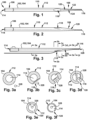
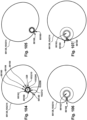
- a modular dilation device 100 is provided.
- the modular dilation device 100 may include a plurality of dilators 102 having alternate configurations, which will be discussed below.
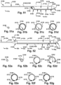
- Figs. 1 , 5, 7, and 8 depict example alternate configurations of the dilators 102.
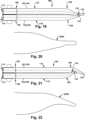
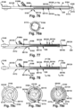
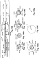
- Figs. 1-2 depict an example alternate configuration for a dilator 102, referred to as a dilator A 104.
- the dilator A 104 has a dilator proximal end 106 and a dilator distal end 108.
- the dilator proximal end 106 and the dilator distal end 108 are longitudinally spaced apart by an elongate dilator body 110.
- the term "longitudinal” is used herein to indicate a substantially horizontal direction, in the orientation of Fig. 1 . At least a portion of the dilator distal end 108 may be inwardly tapered.
- the term “taper” is defined herein as a gradual diminution of thickness, diameter, or width in an elongated object, as is shown by the gradual diminution in diameter of the dilator distal end in Figs. 1-2 .
- the term “inward” is defined herein as a taper that becomes gradually smaller, such as shown as the gradual diminution in diameter between the dilator body 110 and a dilator open tip 116, which will be discussed below, in Figs 1-2 .
- the inward taper such as the taper of the dilator distal end 108, could include no expansion in diameter (or outward taper) distal to the dilator body 110.
- the dilator A 104 has a dilator outer surface 112 and a dilator inner lumen 114.
- the dilator distal end 108 has the dilator open tip 116.
- the dilator inner lumen 114 of the dilator A 104 may extend between the dilator proximal end 106 and the dilator open tip 116.
- the dilator A 104 has a dilator side wall opening 118.
- the dilator side wall opening 118 is longitudinally spaced from the dilator open tip 116.
- the dilator side wall opening 118 is positioned on at least one of the dilator body 110 and the dilator distal end 108.
- the dilator side wall opening 118 selectively places the dilator outer surface 112 in fluid communication with the dilator inner lumen 114.
- the dilator A 104 has a dilator open slit 120.
- the dilator open slit 120 extends between the dilator side wall opening 118 and the dilator open tip 116.
- the dilator open slit 120 has a dilator open slit first surface 122 and a dilator open slit second surface 124.
- the dilator open slit first surface 122 oppositely faces and abuts the dilator open slit second surface 124.
- the dilator open slit first surface 122 and the dilator open slit second surface 124 are elastically separable.
- a force may be applied to separate the dilator open slit first surface 122 and the dilator open slit second surface 124, as that the dilator open slit first surface 122 will no longer be abutting the dilator open slit second surface 124.
- the dilator open slit first surface 122 and the dilator open slit second surface 124 will tend to return toward their original abutting position due to the elastic nature of the material forming the dilator open slit first surface 122 and the dilator open slit second surface 124.
- the dilator A may include a guidewire path 326 for a guidewire 328 to be directed through the dilator open tip 116 and the dilator inner lumen 114, and out from the dilator A 104, such as through the dilator proximal end 106 of the dilator A 104.
- Figs. 4a-f depict cross-sectional views of various points along the dilator A 104, to show the arrangement of the dilator A 104 and the guidewire 328 in Fig. 4 .
- One or more guidewires 328 may be inserted through each, or both, of the guidewire paths 326 shown in Figs. 3 and 4 .
- the dilator distal end 108 has a dilator open tip 116.
- the dilator inner lumen 114 of the dilator B 530 may extend between the dilator proximal end 106 and the dilator open tip 116.
- dilator B includes a guidewire path 326 for a guidewire 328 to be directed through the dilator open tip 116 and the dilator inner lumen 114, and out from the dilator B, such as through the proximal end 106 of the dilator B 530.
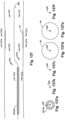
- Fig. 7 depicts an example alternative configuration for the dilator 102, referred to as a dilator C 732. Similar to the dilator A 104, the dilator C 732 has a dilator proximal end 106 and a dilator distal end 108. The dilator proximal end 106 and the dilator distal end 108 are longitudinally spaced apart by an elongate dilator body 110. At least a portion of the dilator distal end 108 may be inwardly tapered.
- the dilator C 732 has a dilator outer surface 112 and a dilator inner lumen 114.
- the dilator C 732 includes a guidewire path 326 for a guidewire 328 to be directed through the dilator open tip 116, through at least a portion of the dilator inner lumen 114, and out from the dilator C 732, such as through the dilator side wall opening 118.
- Figs. 8-9 depict an example alternate configuration for the dilator 102, referred to as a dilator D 834. Similar to the dilator C 732, the dilator D 834 has a dilator proximal end 106 and a dilator distal end 108. The dilator proximal end 106 and the dilator distal end 108 are longitudinally spaced apart by an elongate dilator body 110. At least a portion of the dilator distal end 108 may be inwardly tapered.
- the dilator D 834 has a dilator outer surface 112 and a dilator inner lumen 114.
- the dilator distal end 108 has a dilator open tip 116.
- the dilator D 834 has a dilator side wall opening 118.
- the dilator side wall opening 118 is longitudinally spaced from the dilator open tip 116.
- the dilator side wall opening 118 is positioned on at least one of the dilator body 110 and the dilator distal end 108.
- the dilator side wall opening 118 selectively places the dilator outer surface 112 in fluid communication with the dilator inner lumen 114.
- the dilator inner lumen 114 of the dilator D may extend between the dilator side wall opening 118 and the dilator open tip 116.
- the dilator side wall opening 118 may have a dilator downwardly inclined surface 1335 that extends from the dilator outer surface 112 to the dilator inner lumen 114.
- the term "downward" is defined herein as from a higher to a lower place or condition, as is shown by the dilator downwardly inclined surface 1335 that begins at a higher place (the dilator outer surface 112) and extends to a lower place (the dilator inner lumen 114), such as into the plane of the page in the orientation of Fig. 13 .
- the dilator open tip 116 may be in a side opening configuration.
- the dilator 102 may have a substantially flat surface (the dilator abutting surface 1538) that extends between at least a portion of the dilator body 110 and at least a portion of the dilator distal end 108 as shown in Figs. 15-16.
- Fig. 15 depicts the dilator A 104 having the dilator abutting surface 1538.
- at least a portion of the dilator B 530 may have the dilator abutting surface 1538.
- the dilator open tip 116 of a curved dilator B 530 and at least a portion of the dilator distal end 108 of the curved dilator B 530 may both be inserted into the dilator side wall opening 118 of the dilator A 104, without being inserted into the dilator inner lumen 114 of the dilator A 104.
- the contours of at least one of the dilator distal ends 108, the dilator bodies 110, and the dilator proximal ends 106 may form a relatively smooth tapered surface 2040.
- the term "smooth" is defined herein as moving or progressing without significant breaks, sudden changes, or shifts.
- the smooth tapered surface 2040 may allow for a smooth dilation of a patient tissue access point P.
- the modular dilation device 100 may include a guidewire path 326 for a guidewire 328 to be directed through the dilator open tip 116 of the dilator A 104, through at least a portion of the dilator inner lumen 114 of the dilator A 104, through the dilator side wall opening 118 of the dilator A 104, through the dilator open tip 116 of the dilator B and the dilator inner lumen 114 of the dilator B 530, and out from the dilator B 530, such as through the dilator proximal end 108 of the dilator B 530.
- the dilator open tip 116 of the dilator B 530 is adjacent to the dilator side wall opening 118 of a second dilator A 104b, and the dilator open tip 116 of the second dilator A 104b is adjacent to the dilator side wall opening 118 of a first dilator A 104a.
- the dilator open tip 116 and at least a portion of the dilator distal end 108 of may each be formed at least partially from an elastic material, which would allow for the dilator open tip 116 and at least a portion of the dilator distal end 108 of one dilator 102 to be inserted into the dilator inner lumen 114 of another dilator 102 through the dilator side wall opening 118 of the other dilator 102.
- a dilator B 530 when provided, is operatively joined to a dilator A 104, when provided, the dilator open tip 116 and at least a portion of the dilator distal end 108 of the dilator B 530 is inserted into the dilator inner lumen 114 of the dilator A 104 through the dilator side wall opening 118 of the dilator A 104.
- the dilator open tip 116 and at least a portion of the dilator distal end 108 of the dilator B 530 is inserted into the dilator inner lumen 114 of the dilator A 104 through the dilator side wall opening 118 of the dilator A 104.
- any of the dilators 102 such as the dilators A-D 104, 530, 732, 834, as discussed above, may have a similar configuration as described above for Fig. 26 .
- the dilator open tip 116 and at least a portion of the dilator distal end 108 of the dilator B 530 may be inserted into the dilator inner lumen 114 of a second dilator A 104b through the dilator side wall opening 118 of the second dilator A 104b, and the dilator open tip 116 and at least a portion of the dilator distal end 108 of the second dilator A 104b may be inserted into the dilator inner lumen 114 of a first dilator A 104a through the dilator side wall opening 118 of the first dilator A 104a.
- a guidewire path 326 for a guidewire 328 may be directed through the dilator open tip 116 of the first dilator A 104a, through at least a portion of the dilator inner lumen 114 of the first dilator A 104a, through the dilator open tip 116 of the second dilator A 104b, through at least a portion of the dilator inner lumen 114 of the second dilator A 104b (thus, indirectly traveling through the dilator side wall opening 118 of the first dilator A 104a, as well), through the dilator open tip 116 of the dilator B 530 and the dilator inner lumen 114 of the dilator B 530 (thus, indirectly traveling through the dilator side wall opening 118 of the second dilator B 104b, as well), and out from the dilator B 530, such as through the dilator
- the modular dilation device 100 is provided to the user.
- the modular dilation device 100 may include at least two of any of the configurations of the dilators 102, as discussed above, in any combination, including having multiple dilators 102 with substantially the same configurations.
- the modular dilation device 100 may include at least two of any of the configurations of the dilators 102, as discussed above, in any combination, including having multiple dilators 102 with substantially the same configurations.
- the modular dilation device 100 may include at least two of any of the configurations of the dilators 102, as discussed above, in any combination, including having multiple dilators 102 with substantially the same configurations.
- the alternate dilator 102 configurations are discussed and/or depicted.
- the following descriptions may be applicable to any combination of the alternate configurations of the dilators 102, as described above.
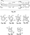
- the guidewire proximal end 2844 is directed into the dilator open tip 116 of a dilator B 530, when provided, through at least a portion of the dilator inner lumen 114 of the dilator B 530, and out from the dilator B 530, such as through the dilator proximal end 106 of the dilator B 530.
- the dilator B 530 is directed to the target patient tissue site T along the guidewire 328 until the dilator open tip 116 of the dilator B 530 is adjacent to the dilator side wall opening 118 of the dilator A 104.
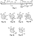
- Figs. 30a-f depict cross-sectional views of various points along the modular dilation device 100, to show the arrangement of the dilators 102 and the guidewire 328 in Fig. 30 .
- the dilator B 530 may be placed in a predetermined relationship with the dilator A 104, wherein the dilator open tip 116 of the dilator B 530 is adjacent to the dilator side wall opening 118 of the dilator A 104.
- the guidewire proximal end 2844 is directed into the dilator open tip 116 of the dilator A 104 and out of the dilator proximal end 106 of the dilator B 530.
- the guidewire proximal end 2844 is directed through the dilator open tip 116 of the dilator A 104 and at least a portion of the dilator inner lumen 114 of the dilator A 104, through the dilator side wall opening 118 of the dilator A 104, through the dilator open tip 116 and the dilator inner lumen 114 of the dilator B 530, and out from the dilator B 530, such as through the dilator proximal end 106 of the dilator B 530. Both the dilator A 104 and the dilator B 530 are then collectively inserted into the target patient tissue site T along the guidewire 328.
- dilator distal end 108 of the dilator B 530 can be thought of as acting as a pivot arrangement to release the dilator A 104 from the guidewire 328.
- Figs. 31a-f depict cross-sectional views of various points along the modular dilation device 100, to show the arrangement of the dilators 102 and the guidewire 328 in Fig. 31 .
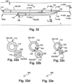
- Figs. 32a-f depict cross-sectional views of various points along the modular dilation device 100, to show the arrangement of the dilators 102 and the guidewire 328 in Fig. 32 .
- a second guidewire 328b may be inserted through the dilator inner lumen 114 of the dilator A 104 and into the target patent tissue site T.
- Figs. 33a-f depict cross-sectional views of various points along the modular dilation device 100, to show the arrangement of the dilators 102 and the guidewires 328, 328b in Fig. 33 . As shown in Fig.
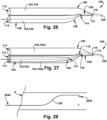
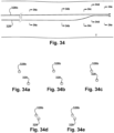
- Figs. 35-41 depict an example sequence of operation of a modular dilation device 100 having three dilators D 834.
- a guidewire distal end 2842 is inserted into a target patient tissue site T through a patient tissue access point P.
- a third dilator D 834c is placed into a predetermined relationship with a first dilator D 834a, wherein the dilator open tip 116 of the third dilator D 834c is adjacent to the dilator side wall opening 118 of the first dilator D 834a.
- the guidewire proximal end 2844 is directed through the dilator open tip 116 of the first dilator D 834a and at least a portion of the dilator inner lumen 114 of the first dilator D 834a, through the dilator side wall opening 118 of the first dilator D 834a, through the dilator open tip 116 of the third dilator D 834c and at least a portion of the dilator inner lumen 114 of the third dilator D 834c, through the dilator side wall opening 118 of the third dilator D 834c, through the dilator open tip 116 and the dilator inner lumen 114 of the second dilator D 834b, and out from the second dilator D 834b, such as through the dilator side wall opening 118 of the second dilator D 834b.
- the first dilator D 834a, the second dilator D 834b, and the third dilator D 834c are collectively inserted into the target patient tissue site T along the guidewire 328 in a longitudinally distal direction (as shown by arrow Y in Fig. 36 ).
- the guidewire proximal end 2844 is directed into the dilator open tip 116 of the third dilator D 834c, through at least a portion of the dilator inner lumen 114 of the third dilator D 834c, and out from the third dilator D 834c, such as through the dilator side wall opening 118 of the third dilator D 834c.
- the third dilator D 834c is directed into the target patient tissue site T along the guidewire 328 until the dilator open tip 116 of the third dilator D 834c is adjacent to the dilator side wall opening 118 of the first dilator D 834a.
- the dilator distal end 108 of the second dilator D 834b may be directed at least one of adjacent to and into the dilator side wall opening 118 of the third dilator D 834c.
- the third dilator D 834c is longitudinally moved toward a proximal direction (shown as the arrow X in Fig.
- the dilator distal end 108 of second dilator D 834b selectively urges the dilator open slit first surface 122 of the third dilator D 834c elastically apart from the dilator open slit second surface 124 of the third dilator D 834c and the third dilator D 834c is removed from the guidewire328, as is shown in Fig. 38 .
- the dilator distal end 108 of the second dilator D 834b can be thought of as a pivot to release the third dilator D 834c from the guidewire 328.
- the dilator open tip 116 and at least a portion of the dilator distal end 108 of the second dilator D 834b may then be directed at least one of adjacent to and into the dilator side wall opening 118 of the first dilator D 834a by longitudinally moving the second dilator D 834b in the distal direction.
- the second dilator D 834b may then be directed at least one of adjacent to and into the dilator side wall opening 118 of the first dilator D 834a by longitudinally moving the second dilator D 834b in the distal direction.
- the dilator distal end 108 of the second dilator D 834b selectively urges the dilator open slit first surface 122 of the first dilator D 834a elastically apart from the dilator open slit second surface 124 of the first dilator D 834a and the first dilator D 834a is removed from the guidewire 328, while maintaining the guidewire 328 at the target patient tissue site T, as is shown in Fig. 41 .
- the dilator distal end 108 of the second dilator D 834b can be thought of as a pivot to release the first dilator D 834a from the guidewire 328.
- Fig. 41 depicts the second dilator D 834b maintained on the guidewire 328 at the target patient tissue site T.
- the second dilator D 834b may be removed from the guidewire 328 by directing another dilator 102 along the guidewire 328 to remove the second dilator D 834b from the guidewire 328, in a similar sequence as described above.
- the second dilator D 834b may be moved in the proximal direction to remove the second dilator D 834b from the guidewire 328 and the target patient tissue site T.
- additional guidewires 328 may be directed through each of the first and third dilators D 834a, 834c to the target patient tissue site T, in a similar sequence as described above.
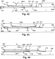
- Figs. 42-48 depict an example sequence of operation of a modular dilation device 100 that has two dilators A 104 and one dilator B 530.
- a guidewire distal end 2842 is inserted into a target patient tissue site T through a patient tissue access point P.
- a second dilator A 104b is placed into a predetermined relationship with a first dilator A 104a, wherein the dilator open tip 116 of the second dilator A 104b is adjacent to the dilator side wall opening 118 of the first dilator A 104a.
- a dilator B 530 is placed into a predetermined relationship with the second dilator A 104b, wherein the dilator open tip 116 of the dilator B 530 is adjacent to the dilator side wall opening 118 of the second dilator A 104b. As shown in Figs. 42-43 , the guidewire proximal end 2842 is directed into the dilator open tip 116 of the first dilator A 104a and out of the dilator B 530.
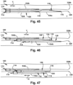
- the guidewire proximal end 2844 is directed through the dilator open tip 116 of the first dilator A 104a and at least a portion of the dilator inner lumen 114 of the first dilator A 104a, through the dilator side wall opening 118 of the first dilator A 104a, through the dilator open tip 116 of the second dilator A 104b and at least a portion of the dilator inner lumen 114 of the second dilator A 104b, through the dilator side wall opening 118 of the second dilator A 104b, through the dilator open tip 116 and the dilator inner lumen 114 of the dilator B 530, and out from the dilator B 530, such as through the dilator proximal end 106 of the dilator B 530.
- the first dilator A 104a, the second dilator A 104b, and the dilator B 530 are collectively inserted into the target patient tissue site T along the guidewire 328 in a longitudinally distal direction (as shown by arrow Y in Fig. 43 ).
- the two dilators A 104a-b and the one dilator B 530 may be inserted into the target patient tissue site T sequentially.
- a guidewire proximal end 2842 may be directed into the dilator open tip 116 of the first dilator A 104a, through at least a portion of the dilator inner lumen 114 of the first dilator A 104a, and out from the first dilator A 104, such as through the dilator side wall opening 118 of the first dilator A 104a.
- the second dilator A 104b is directed to the target patient tissue site T along the guidewire 328 in the longitudinally distal direction until the dilator open tip 116 of the second dilator A 104b is adjacent to the dilator side wall opening 118 of the first dilator A 104a.
- the guidewire proximal end 2844 is directed into the dilator open tip 116 of the dilator B 530, through at least a portion of the dilator inner lumen 114 of the dilator B 530, and out from the dilator B 530, such as through the dilator proximal end 106 of the dilator B 530.
- the dilator B 530 is directed to the target patient tissue site T along the guidewire 328 in the longitudinally distal direction until the dilator open tip 116 of the dilator B 530 is adjacent to the dilator side wall opening 118 of the second dilator A 104b.
- the dilator distal end 108 of the dilator B 530 selectively urges the dilator open slit first surface 122 of the second dilator A 104b elastically apart from the dilator open slit second surface 124 of the second dilator A 104b and the second dilator A 104b is removed from the guidewire 328.
- the dilator distal end 108 of the dilator B 530 can be thought of as a pivot arrangement to release the second dilator A 104b from the guidewire 328.
- a second guidewire 328b may be directed through the second dilator A 104b to the target patient tissue site T in the longitudinally distal direction.
- the dilator open tip 116 and at least a portion of the dilator distal end 108 of one dilator 120 may be capable of being inserted into the dilator inner lumen 114 of another dilator 102 through the dilator side wall opening 118 of the other dilator 102.
- the user inserts the guidewire distal end 2842 into a target patient tissue site T through a patient tissue access point P.
- the user places the a dilator 102, such as a dilator B 530, into a predetermined relationship with another dilator 102, such as a dilator A 104, wherein the dilator open tip 116 of the dilator B 530 and at least a portion of the dilator distal end 108 of the dilator B 530 is inserted into the dilator inner lumen 114 of the dilator A 104 through the dilator side wall opening 118 of the dilator A 104.
- the user directs a guidewire proximal end 2844 into the dilator open tip 116 of the dilator A 104 and out of the dilator B 530, such as through the proximal end 106 of the dilator B 530.
- the guidewire proximal end 2844 is directed through the dilator open tip 116 and at least a portion of the dilator inner lumen 114 of the dilator A 104, through the dilator open tip 116 and the dilator inner lumen 114 of the dilator B 830 (thus, indirectly traveling through the dilator side wall opening 118 of the dilator A 104, as well), and out from the dilator B 530, such as through the dilator proximal end 106 of the dilator B 530.
- the user may then collectively insert both the dilator A 104 and the dilator B 530 into the target patient tissue site T along the guidewire 328.
- at least one of the dilator A 104 and the dilator B 530 may be removed from the guidewire 328, in a similar sequence as described above.
- the guidewire proximal end 2844 may be directed into the dilator open tip 116 of the first dilator A 104a and out of the dilator B 530, such as through the dilator proximal end 106 of the dilator B 530.
- the guidewire proximal end 2844 is directed through the dilator open tip 116 and at least a portion of the dilator inner lumen 114 of the first dilator A 104a, through the dilator open tip 116 and at least a portion of the dilator inner lumen 114 of the second dilator A 104b (thus, indirectly traveling through the dilator side wall opening 118 of the first dilator A 104a, as well), through the dilator open tip 116 and the dilator inner lumen 114 of the dilator B 530 (thus, indirectly traveling through the dilator side wall opening 118 of the second dilator A 104b, as well), and out from the dilator B 530, such as through the proximal end 106 of the dilator B 530.
- any of the dilator 102 configurations of the modular dilation device 100 may be at least partially formed from silicone, polyethylene, polypropylene, stainless steel, titanium, any other biocompatible material, or any combination thereof.
- any of the dilator 102 configurations of the modular dilation device 100 may be a stiffener, and or may be at least a part of at least one of a sheath, catheter, tear-away sheath, any other suitable medical instrument, or any combination thereof. Further, it is contemplated that any of the dilator 102 configurations may be disposed within one or more sheaths, which allows for the insertion of multiple sheaths into a target patient tissue site T through a single access point P.
- a first dilator A 104a may be disengaged from the guidewire 328 within the target patient tissue site T, as previously described.
- a second guidewire 328b may be separately inserted through the dilator inner lumen 114 of the first dilator A 104a into the target patient tissue site T.
- the first and second dilators A 104a-b may be removed from the target patient tissue site T, as described above. Once the dilators 102 are removed, medical instruments may be inserted through the sheaths to the target patient tissue site T.
- the modular dilation device 100 may provide the user with the ability to insert multiple dilators 102 into a target patient tissue site T through a single patient tissue access point P.
- the ability to insert multiple dilators 102 into a target patient tissue site T through a single patient tissue access point P may assist in reducing potential trauma, complications, and/or risks to the patient that result from the creation of multiple patient tissue access points P. For example, if a dilator A 104 and a dilator B 530 were inserted through two separate patient tissue access points P, the trauma, risks, and complications associated with said insertions could be increased as compared to the insertion of the dilator A 104 and the dilator B 530 through a single patient tissue access point P. Further, the ability to use a single patient tissue access point P instead of having to create multiple patient tissue access points P may reduce the procedure time and the costs that would be associated with creating multiple patient tissue access points P.
- the modular dilation device 100 may allow for a smaller patient tissue access point P than what may be necessary for the insertion of multiple dilators 102 that are not operatively joined in the manner as described above.
- the patient tissue access point P may be smaller in diameter than desirable for inserting multiple dilators that are not combined as described herein.
- the implant delivery system 5146 may include a number of outer sheaths 5148 having alternate configurations, which will be discussed below.
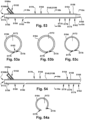
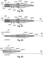
- Figs. 51, 52 , 53, and 54 depict example alternative configurations of the outer sheath 5148.
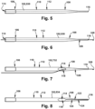
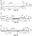
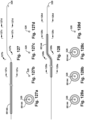
- Fig. 51 depicts an example alternative configuration for the outer sheath 5148, referred to as an outer sheath A 5150.
- the outer sheath A 5150 has an outer sheath proximal end 5152 and an outer sheath distal end 5154.
- the outer sheath proximal end 5152 has an outer sheath delivery element 5156.
- the outer sheath delivery element may 5156 be a stiff wire, or any other appropriate element for delivering the outer sheath to, or from, a target patient tissue site T.
- the stiff wire may be, for example, a solid (i.e., non-hollow) element, such as, but not limited to, a stainless steel or plastic wire.
- the stiff wire may instead be, for example, an at least partially tubular or hollow element, such as, but not limited to a catheter with an inner lumen for a guidewire.
- the outer sheath distal end 5154 has an implant holding pod 5158.
- the implant holding pod 5158 has an implant holding pod proximal end 5160 and an implant holding pod distal end 5162.
- the implant holding pod 5158 has an implant holding pod body 5164 longitudinally extending between the implant holding pod proximal and distal ends 5160, 5162.
- the implant holding pod proximal end 5160 has an implant holding pod proximal opening 5166.
- the implant holding pod proximal opening 5166 of the outer sheath A 5150 may face substantially laterally downward. At least a portion of the implant holding pod distal end 5162 may be inwardly tapered.
- the implant holding pod 5158 has an implant holding pod open slit 5174.
- the implant holding pod open slit 5174 may extend at least partially between the implant holding pod open tip 5168 and the implant holding pod proximal end 5160.
- the implant holding pod open slit 5147 of the outer sheath A 5150 may extend between the implant holding pod open tip 5168 and the implant holding pod proximal opening 5166.
- the implant holding pod open slit 5174 has an implant holding pod open slit first surface 5176 and an implant holding pod open slit second surface 5178.
- the implant holding pod open slit first surface 5176 oppositely faces and abuts the implant holding pod open slit second surface 5178.
- the implant holding pod open slit first surface 5176 and the implant holding pod open slit second surface 5178 may laterally overlap to provide a labyrinth-type seal, similar to as previously described.
- the implant holding pod open slit first surface 5176 and the implant holding pod open slit second surface 5178 may be selectively elastically separable. That is, a force may be applied to separate the implant holding pod open slit first surface 5176 and the implant holding pod open slit second surface 5178, as that the implant holding pod open slit first surface 5176 will no longer be abutting the implant holding pod open slit second surface 5178.
- the outer sheath distal end 5154 has an implant holding pod 5158.
- the implant holding pod 5158 has an implant holding pod proximal end 5160 and an implant holding pod distal end 5162.
- the implant holding pod 5158 has an implant holding pod body 5164 longitudinally extending between the implant holding pod proximal and distal ends 5160, 5162.
- the implant holding pod proximal end 5160 has an implant holding pod proximal opening 5166.
- the implant holding pod proximal opening 5166 of the outer sheath A may face substantially laterally upward.
- the implant holding pod 5158 has an implant holding pod open slit 5174.
- the implant holding pod open slit 5174 may extend at least partially between the implant holding pod open tip 5168 and the implant holding pod proximal end 5160.
- the implant holding pod open slit 5174 of the outer sheath B 5180 may extend between the implant holding pod open tip 5168 and the implant holding pod side wall opening 5182.
- the implant holding pod open slit 5174 has an implant holding pod open slit first surface 5176 and an implant holding pod open slit second surface 5178.
- the implant holding pod open slit first surface 5176 oppositely faces and abuts the implant holding pod open slit second surface 5178.
- Fig. 53 depicts an alternative configuration for the outer sheath 5148, referred to as an outer sheath C 5184. Similar to the outer sheath B 5180, the outer sheath C 5184 has an outer sheath proximal end 5152 and an outer sheath distal end 5154. The outer sheath proximal end 5152 has an outer sheath delivery element 5156. At least one of the outer sheath proximal end 5152 and the outer sheath distal end 5154 has an implant holding pod 5158. The implant holding pod 5158 has an implant holding pod proximal end 5160 and an implant holding pod distal end 5162.
- the implant holding pod distal end 5162 may be inwardly tapered.
- the implant holding pod distal end 5162 has an implant holding pod open tip 5168.
- the implant holding pod 5158 has an implant holding pod outer surface 5170 and an implant holding pod lumen 5172.
- the implant holding pod lumen 5172 may extend between the implant holding pod open tip 5168 and at least one of an implant holding pod side wall opening 5182, and the first and second implant holding pod proximal openings 5166a-b.
- the implant holding pod inner lumen 5172 is at least partially configured for selectively holding an expandable implant M therein.
- the implant holding pod 5158 has an implant holding pod open slit 5174.
- the implant holding pod open slit 8174 may extend at least partially between the implant holding pod open tip 5168 and the implant holding pod proximal end 5160.
- the implant holding pod open slit 5174 of the outer sheath C 5184 may extend between the implant holding pod open tip 5168 and the implant holding pod side wall opening 5182.
- the implant holding pod open slit 5168 has an implant holding pod open slit first surface 5176 and an implant holding pod open slit second surface 5178.
- the implant holding pod open slit first surface 5176 oppositely faces and abuts the implant holding pod open slit second surface 5178.
- the implant holding pod open slit first surface 5176 and the implant holding pod open slit second surface 5178 may be selectively elastically separable.
- Fig. 54 depicts an alternative configuration for the outer sheath 5148, referred to as an outer sheath D 5186. Similar to the outer sheath C 5184, the outer sheath D 5186 has an outer sheath proximal end 5152 and an outer sheath distal end 5154. The outer sheath proximal end 5152 has an outer sheath delivery element 5156. The outer sheath delivery element 5156 may extend between the outer sheath proximal end 5152 and an implant holding pod side wall opening 5182. The outer sheath delivery element 5156 may be, but is not limited to, a stiff wire.
- the implant holding pod proximal end 5166 of the outer sheath D 5186 may have an implant holding pod proximal opening 5166.
- a first implant holding pod proximal opening 5166a of the outer sheath D 5186 may face substantially laterally upward.
- a fluid, such as saline, may be directed through the first implant holding pod proximal opening 5166a, when provided, to flush a target patient tissue site T when the outer sheath C 5184 is located at the target patient tissue site T.
- a second implant holding pod proximal opening 5166b of the outer sheath D 5186 may be longitudinally facing.
- the implant holding pod distal end 5162 of the outer sheath D 5186 might not be inwardly tapered.
- the implant holding pod distal end 5162 and the implant holding pod body 5164 of the outer sheath D may be substantially level.
- the term "level” is defined herein as being substantially even or unvarying in height, as is shown by the implant holding pod distal end 5162 not having a gradual or stepwise diminution and/or increase in diameter in Fig. 54 .
- the implant holding pod distal end 5162 has an implant holding pod open tip 5168.
- the implant holding pod 5158 has an implant holding pod outer surface 5170 and an implant holding pod lumen 5172.
- the implant holding pod open slit first surface 5176 and the implant holding pod open slit second surface 5178 may laterally overlap to provide a labyrinth-type seal, similar to as previously described.
- the implant holding pod open slit first surface 5176 and the implant holding pod open slit second surface 5178 may be selectively elastically separable.
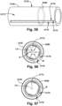
- any of the outer sheath 5148 alternate configurations discussed above may have at least one c-clip 5588 selectively disposed on a portion of the implant holding pod outer surface 1570 that is adjacent to the implant holding pod open slit 5174.
- the at least one c-clip 5588 may be selectively disposed within (e.g., via overmolding) at least a portion of the implant holding pod inner lumen 5172 that is adjacent to the implant holding pod open slit 5174.
- the at least one c-clip 5588 may be embedded in the outer sheath between the implant holding pod outer surface 5170 and the implant holding pod inner lumen 5172, and adjacent to the implant holding pod open slit 5174.
- the c-clip 5588 at least partially selectively prevents the implant holding pod open slit first surface 5176 from elastically separating from the implant holding pod open slit second surface 5178 when a self-expanding implant M is disposed within the implant holding pod inner lumen 5172.
- an expandable implant M placed within the implant holding pod inner lumen 5172 in a collapsed condition may move toward an expanded condition due to the natural properties of the expandable implant M.
- the implant holding pod open slit first surface 5176 is elastically separable from the implant holding pod second surface 5178, the movement of the expandable implant M toward the expanded condition might cause the implant holding pod open slit first surface 5176 to elastically separate from the implant holding pod open slit second surface 5178.
- the implant holding pod open slit first surface 5176 is elastically separable from the implant holding pod second surface 5178.
- the c-clip 5588 when at least one c-clip 5588 is positioned on the implant holding pod outer surface 5170 and/or within the implant holding pod inner lumen 5172, the c-clip 5588 provides a radially inward pressure or bias to at least partially selectively prevent the expandable implant M from moving from a collapsed condition toward an expanded condition, and thus at least partially prevents the expandable implant M from elastically separating the implant holding pod open slit first surface 5176 from the implant holding pod open slit second surface 5178.
- the term "radial” is used herein to indicate a direction substantially perpendicular to the "lateral" direction, and is shown via arrows R in Fig. 56 extending toward a central longitudinal axis LA, in the orientation of Fig. 56. Figs.
- the c-clip 5588 may either partially and/or fully laterally extend circumferentially about the outer sheath 5148 from the implant holding pod open slit first surface 5176 to the implant holding pod open slit second surface 5178.
- the c-clip 5588 may be at least partially radiopaque, and thus visible under radiography or other intraoperative imaging techniques.
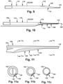
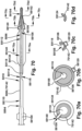
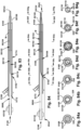
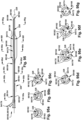
- Fig. 59 depicts an alternate configuration for the shaft 5890, referred to as a shaft B 59122. Similar to the shaft A 5892, the shaft B 59122 has a shaft proximal end 5894, a shaft distal end 5896, and a shaft body 5898 that longitudinally extends between the shaft proximal and distal ends 5894, 5896.
- the shaft proximal end 5894 has a shaft delivery element 58100.
- the shaft distal end 5896 has an implant delivery element 58102.
- the implant delivery element 58102 of the shaft B 59122 has an implant delivery element outer surface 58104 for selectively circumferentially mounting an expandable implant M thereon.
- the implant delivery element outer surface 58104 has at least one radially extending projection 58106.
- the radially extending projection 58106 of the shaft B 59122 is for substantially preventing the egress of an expandable implant M mounted circumferentially about the implant delivery element outer surface 58104 from a desired position on the implant delivery element outer surface 58104.
- At least one of the shaft body 5898 and the implant delivery element 58102 has a shaft open slit 58108.
- the shaft body 5898 has a shaft body proximal end 58110, a shaft body distal end 58112, and a shaft body length 58114 that longitudinally extends between the shaft body proximal end 58110 and the shaft body distal end 58112. At least one of the shaft body proximal end 58110, the shaft body distal end 58112, and the shaft body length 58114 has a shaft side wall opening 58116.
- the shaft side wall opening 58116 is in selective fluid communication with the shaft open slit 58108.
- the shaft open slit 58108 of the shaft B 59122 may extend between the shaft side wall opening 58116 and an implant delivery element open tip 59124.
- Fig. 60 depicts an alternate configuration for the shaft 5890, referred to as a shaft C 60126. Similar to the shaft A 5892, the shaft C 60126 has a shaft proximal end 5894, a shaft distal end 5896, and a shaft body 5898 that longitudinally extends between the shaft proximal and distal ends 5894, 5896.
- the shaft proximal end 5894 has a shaft delivery element 58100.
- the shaft distal end 5896 has an implant delivery element 58102.
- the implant delivery element 58102 of the shaft C 60126 has an implant delivery element outer surface 58104 and a radially extending projection 58106 for selectively contacting and selectively pushing an expandable implant M. At least one of the shaft body 5898 and the implant delivery element 58102 has a shaft open slit 58108.
- the shaft body 5898 has a shaft body proximal end 58110, a shaft body distal end 58112, and a shaft body length 58114 that longitudinally extends between the shaft body proximal end 58110 and the shaft body distal end 58112. At least one of the shaft body proximal end 58110, the shaft body distal end 58112, and the shaft body length 58114 has a shaft side wall opening 58116.
- the shaft side wall opening 58116 is in selective fluid communication with the shaft open slit 58108.
- the shaft open slit 58108 of the shaft C 60126 may extend between the shaft side wall opening 58116 and an implant delivery element open tip 59124.
- At least a portion of the shaft open slit 58108 and at least a portion of the shaft side wall opening 58116 may collectively form a shaft lumen 58118 for at least partially selectively holding a guidewire 328 therein.
- At least one of the shaft body proximal end 58110, shaft body distal end 58112, and the shaft body length 58114 may have an outer sheath splitter 58120 for facilitating the elastic separation of the implant holding pod open slit first surface 5176 and the implant holding pod open slit second surface 5178.
- Figs. 60a-c depict cross-sectional views of various points along the shaft C 60126, to show structural features of the shaft B 60126.
- the outer sheath splitter 58120 may be arrow-shaped.
- the term "arrow-shaped" is defined herein as a linear figure having a wedge-shaped edge, as one used on a map or architectural drawing, to indicate direction or placement.
- the arrow-shaped outer sheath splitter 58120 may point toward a longitudinally distal direction (shown as an arrow Y in Fig. 61 ).
- the arrow-shaped outer sheath splitter 58120 may point downward toward an implant holding pod side wall opening 5182 of an outer sheath 5148 when the shaft C 60126 is operably joined to an outer sheath 5182.
- the shaft C 60126 is shown having the arrow-shaped outer sheath splitter 58120, any of the outer sheath splitters 58120 of the alternate configurations of the shaft 5890 may be arrow-shaped.
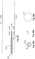
- Fig. 62 depicts an alternate configuration for the shaft 5890, referred to as a shaft D 62128. Similar to the shaft C 60126, the shaft D 62128 has a shaft proximal end 5894, a shaft distal end 5896, and a shaft body 5898 longitudinally extending between the shaft proximal and distal ends 5894, 5896.
- the shaft proximal end 5894 has a shaft delivery element 58100.
- the shaft distal end 5896 has an implant delivery element 58102.
- the implant delivery element 58102 of the shaft A 5892 has an implant delivery element outer surface 58104 and a radially extending projection 58106 for selectively contacting and selectively pushing an expandable implant M. At least one of the shaft body 5898 and the implant delivery element 58102 has a shaft open slit 58108.
- the radially extending projection 58106 may additionally, or instead, be used for a smooth atraumatic transition of the implant delivery system 5146 into the target patient tissue site T.
- the projection 58106 may be a radially extending conical head.
- the conical head may point, or narrow, toward a longitudinally distal direction.
- the term "conical” is defined herein as resembling a solid bounded by a circular or other closed plane base and the surface formed by line segments joining every point of the boundary of the base to a common vertex.
- At least one of the shaft body 5898 and the implant delivery element 58102 has a shaft open slit 58108.
- At least a portion of the shaft open slit 58108 and at least a portion of the shaft side wall opening 58116 may collectively form a shaft lumen 58118 for at least partially selectively holding a guidewire 328 therein.
- At least one of the shaft body proximal end 58110, the shaft body distal end 58112, and the shaft body length 58114 may have an outer sheath splitter 58120 for facilitating the elastic separation of the implant holding pod open slit first surface 5176 and the implant holding pod open slit second surface 5178.
- the conical head projection 58106 may have at least one elastic clamp 64132 that longitudinally extends in the proximal direction (shown as an arrow Y in Fig. 64 ).
- the elastic clamp 64132 is for selectively preventing the implant holding pod open slit first surface 5176 from elastically separating from an implant holding pod open slit second surface 5178 when the shaft 5890 is operably joined to the outer sheath 5148, as will be described in more detail below.
- the elastic clamp 64132 is capable of moving between a collapsed condition ( Figs. 64 and 66 ) and an expanded condition ( Figs. 65 and 67 ). As shown in Figs. 66-67 , at least a portion of the implant delivery element 58102 may not have an open slit.
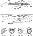
- Fig. 68 depicts an alternate configuration for the shaft 5890, referred to as a shaft F 68134.
- the shaft F 68134 has a shaft proximal end 5894, a shaft distal end 5896, and a shaft body 5898 that longitudinally extends between the shaft proximal and distal ends 5894, 5896.
- the shaft proximal end 5894 has a shaft delivery element 58100.
- the shaft distal end 5896 has an implant delivery element 58102.
- the implant delivery element 58102 of the shaft F 68134 has an implant delivery element outer surface 58104 and a radially extending projection 58106 for selectively contacting and selectively pushing an expandable implant M.
- At least one of the shaft body 5898 and the implant delivery element 58102 has a shaft open slit 58108.
- the implant delivery element 58102 of the shaft F 68134 has the shaft open slit 58108.
- At least one of the shaft body proximal end 58110, the shaft body distal end 58112, and the shaft body length 58114 may have an outer sheath splitter 58120 for facilitating the elastic separation of the implant holding pod open slit first surface 5176 and the implant holding pod open slit second surface 5178.
- at least one of the shaft body 5898 and the implant delivery element 58102 of the shaft F 68134 may be at least partially curved and/or at least partially formed from an elastic material.
- At least one of the shaft body proximal end 58110, the shaft body distal end 58112, and the shaft body length 58114 may have an outer sheath splitter 58120 for facilitating the elastic separation of the implant holding pod open slit first surface 5176 and the implant holding pod open slit second surface 5178.
- at least one of the shaft body 5898 and the implant delivery element 58102 of the shaft G 68136 may be at least partially curved and/or at least partially formed from an elastic material.
- the shaft G 68136 may have an expandable balloon 69138 positioned on at least one of the shaft body 5898 and the shaft distal end 5896.
- the conical head projection 58106 of the shaft H 70142 may undergo a partial rotation until an outer sheath splitter 58120 engages an implant holding pod open slit 5174 of the outer sheath 5148 to facilitate the elastic separation of the implant holding pod open slit first surface 5176 and the implant holding pod open slit second surface 5178.
- the conical head projection 58106 may act as a "self-centering" element when the shaft H 70142 is operably joined to an outer sheath 5180.
- At least one of the shaft body 5898 and the implant delivery element 58102 has a shaft open slit 58108.
- At least one of the shaft body proximal end 58110, the shaft body distal end 58112, and the shaft body length 58114 has an outer sheath splitter 58120 for facilitating the elastic separation of the implant holding pod open slit first surface 5176 and the implant holding pod open slit second surface 5178.
- the outer sheath splitter 58120 may be arrow-shaped.
- the arrow-shaped outer sheath splitter 58120 may point toward a longitudinally distal direction (shown as an arrow Y in Fig. 71 ).
- the implant delivery system 5146 including any of the alternate configurations of the outer sheaths 5148 may be operatively joined to any of the alternate configurations of the shafts 5890.
- the implant delivery system 5146 including any of the alternate configurations of the outer sheaths 5148 may be operatively joined to any of the alternate configurations of the shafts 5890.
- the alternate configurations of the outer sheaths 5148 and the alternate configurations of the shafts 5890 are discussed and/or depicted herein.
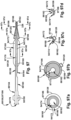
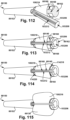
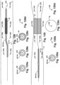
- Fig. 72 depicts the outer sheath A 5150 operably joined to the shaft A 5892.
- the outer sheath A 5150 is operably joined to the shaft A 5892, at least one of the shaft body 5898 and the implant delivery element 58102 may be positioned within the implant holding pod lumen 5172.
- the implant delivery element outer surface 58104 may have an expandable implant M disposed thereon, wherein the implant holding pod inner lumen 5172 at least partially prevents the expandable implant M from moving from a collapsed condition toward an expanded condition.
- At least a portion of the shaft open slit 58108 may be selectively laterally spaced from the implant holding pod open slit 5174. In this configuration, as shown in Fig.
- Fig. 73 depicts the outer sheath B 5180 operably joined to the shaft A 5892.
- the outer sheath B 5180 When the outer sheath B 5180 is operably joined to the shaft A 5892, at least one of the shaft delivery element 58100, the shaft body 5898, and the implant delivery element 58102 may be positioned within the implant holding pod inner lumen 5172.
- the shaft delivery element 58100 may extend through the implant holding pod proximal opening 5166.
- the implant delivery element outer surface 58104 may have an expandable implant M disposed thereon, wherein the implant holding pod inner lumen 5172 at least partially prevents the expandable implant M from moving from a collapsed condition toward an expanded condition.
- At least a portion of the shaft open slit 58108 may be selectively laterally spaced from the implant holding pod open slit 5174.
- the shaft side wall opening 58116 may be aligned with the implant holding pod side wall opening 5182. In this configuration, as shown in Fig.
- Fig. 74 depicts the outer sheath B 5180 operably joined to the shaft B 59122.
- the outer sheath B 5180 When the outer sheath B 5180 is operably joined to the shaft B 59122, at least one of the shaft delivery element 58100, the shaft body 5898, and the implant delivery element 58102 may be positioned within the implant holding pod inner lumen 5172.
- the shaft delivery element 58100 may extend through the implant holding pod proximal opening 5166.
- the implant delivery element outer surface 58104 may have an expandable implant M disposed thereon, wherein the implant holding pod lumen 5172 prevents the expandable implant M from moving from a collapsed condition toward an expanded condition.
- At least a portion of the shaft open slit 58108 may be selectively laterally spaced from the implant holding pod open slit 5174.
- the shaft side wall opening 58116 may be aligned with the implant holding pod side wall opening 5182. In this configuration, as shown in Fig.
- the implant delivery system 5146 may include a guidewire path 326 for a guidewire 328 to be directed through the implant holding pod open tip 5168, through at least a portion of the implant holding pod lumen 5172, through the implant delivery element open tip 59124, through the shaft lumen 58118 (thus, indirectly traveling through the implant holding pod lumen 5172 of the outer sheath B 5180, as well), through the shaft side wall opening 58116, and out from the outer sheath B 5180, such as through the implant holding pod side wall opening 5182.
- Figs. 74a-c depict cross-sectional views of various points along the implant delivery system 5146, to show the arrangement of the outer sheath B 5180, the shaft B 59122, the guidewire 328, and the expandable implant M in Fig. 74 .
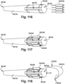
- Fig. 75 depicts the outer sheath A 5150 operably joined to the shaft A 5892, which has an arrow-shaped outer sheath splitter 58120.
- the outer sheath A 5150 is operably joined to the shaft A 5892, at least one of the shaft body 5898 and the implant delivery element 58102 may be positioned within the implant holding pod lumen 5172.
- the implant delivery element outer surface 58104 may have an expandable implant M disposed thereon, wherein the implant holding pod lumen 5172 at least partially prevents the expandable implant M from moving from a collapsed condition toward an expanded condition. At least a portion of the shaft open slit 58108 may be selectively laterally spaced from the implant holding pod open slit 5174.
- the implant delivery system 5146 may include a guidewire path 326 for a guidewire 628 to be directed through the implant holding pod open tip 5168, through at least a portion of the implant holding pod lumen 5172, through the implant holding pod proximal opening 5166 and the shaft lumen 58118, and out from the shaft A 5892, such as through the shaft side wall opening 58116.
- Figs. 75a-e depict cross-sectional views of various points along the implant delivery system 5146, to show the arrangement of the outer sheath A 5150, the shaft A 5892, and the expandable implant M in Fig. 75 .
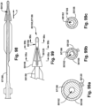
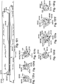
- Fig. 76 depicts the outer sheath C 5184 operably joined to the shaft D 62128.
- the outer sheath C 5184 When the outer sheath C 5184 is operably joined to the shaft D 62128, at least one of the shaft body 5898 and the implant delivery element 58102 may be positioned within the implant holding pod lumen 5172.
- the shaft body 5898 of shaft D 62128 may at least partially extend through the second implant holding pod proximal opening 5166b.
- the implant holding pod lumen 5172 may have an expandable implant M therein.
- the implant holding pod lumen 5172 at least partially prevents the expandable implant M from moving from a collapsed condition toward an expanded condition.
- the implant delivery system 5146 may include a guidewire path 326 for a guidewire 328 to be directed through the implant holding pod open tip 5168, through at least a portion of the implant holding pod lumen 5172, through the implant delivery element open tip 59124, through the shaft lumen 58118 (thus, indirectly traveling through the implant holding pod lumen 5172 of the outer sheath C 5184, as well), through the shaft side wall opening 58116, and out from the outer sheath C 5184, such as through the implant holding pod side wall opening 5182.
- Figs. 76a depicts a cross-sectional view of a point along the implant delivery system 5146, to show the arrangement of the outer sheath C 5184 and the expandable implant M in Fig. 76 .
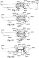
- Fig. 77 depicts the outer sheath D 5186 operably joined to the shaft E 63130.
- the outer sheath D 5186 When the outer sheath D 5186 is operably joined to the shaft E 63130, at least one of the shaft body 5898 and the implant delivery element 58102 may be positioned within the implant holding pod lumen 5172.
- the shaft body 5898 of shaft D 62128 may at least partially extend through the second implant holding pod proximal opening 5166b.
- the conical head projection 58106 may be longitudinally adjacent to the implant holding pod open tip 5168.
- the implant delivery element outer surface 58104 may have an expandable implant M disposed thereon, wherein the implant holding pod lumen 5172 at least partially prevents the expandable implant M from moving from a collapsed condition toward an expanded condition.
- the implant delivery system 5146 may include a guidewire path 326 for a guidewire 328 to be directed through the implant delivery element open tip 59124, through at least a portion of the shaft lumen 58118 (thus, indirectly traveling through the implant holding pod open tip 5168 and the implant holding pod lumen 5172 of the outer sheath D 5186, as well), through the shaft side wall opening 58116, and out from the outer sheath D 5186, such as through the implant holding pod side wall opening 5182.
- the shaft side wall opening 58116 may be aligned with the implant holding pod side wall opening 5182.
- the implant delivery system 5146 may include a guidewire path 326 for a guidewire 328 to be directed through the implant delivery element open tip 59124, through at least a portion of the shaft lumen 58118 (thus, indirectly traveling through the implant holding pod open tip 5168 and the implant holding pod lumen 5172 of the outer sheath C 5184, as well), through the shaft side wall opening 58116, and out from the outer sheath C 5184, such as through the implant holding pod side wall opening 5184.
- Figs. 78a-c depict cross-sectional views of various points along the implant delivery system 5146, to show the arrangement of the outer sheath C 5184, the shaft E 63130, the elastic clamp 64132, and the expandable implant M in Fig. 78 .
- Fig. 79 depicts the outer sheath C 5184 operably joined to the shaft F 68134.
- the outer sheath C 5184 When the outer sheath C 5184 is operably joined to the shaft F 68134, at least one of the shaft body 5898 and the implant delivery element 58102 may be positioned within the implant holding pod lumen 5172 through the implant holding pod side wall opening 5182.
- the implant holding pod lumen 5172 may have an expandable implant M therein.
- the implant holding pod lumen 5172 at least partially prevents the expandable implant M from moving from a collapsed condition toward an expanded condition.
- the projection 58106 of the shaft D 62128 may be in operative engagement with the expandable implant M by locating at least a portion of the projection 58106 in abutment with the expandable implant M.
- a collapsed expandable implant M may be placed within the implant holding pod lumen 5172 prior to inserting at least a portion of the shaft 5890 into the implant holding pod lumen 5172.
- the collapsed expandable implant M may be placed in operative engagement with the implant delivery element 58102 by mounting the expandable implant M to the implant delivery element outer surface 58104.
- a guidewire proximal end 2844 may be directed through the implant holding pod open tip 5168, through at least a portion of the implant holding pod lumen 5172, through the implant holding pod proximal opening 5166 and the shaft lumen 58118, and out from the shaft A 5892, such as through the shaft side wall opening 58116.
- the implant delivery system 5146 is directed to the target patient tissue site T along the guidewire 328.
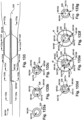
- Figs. 80a-d depict cross-sectional views of various points along the implant delivery system 5146, to show the arrangement of the outer sheath A 5150, the shaft A 5892, the guidewire 328, and the expandable implant M in Fig. 80 .
- the movement of the outer sheath A 5160 in the longitudinally proximal direction causes the outer sheath splitter 58120 to move along the implant holding pod open slit 5174 to selectively urge the implant holding pod open slit first surface 5176 elastically apart from the implant holding pod open slit second surface 5178 and accordingly push the guidewire 328 from the implant holding pod lumen 5172, while maintaining the guidewire 328 and the shaft A 5892 at the target patient tissue site T.
- the properties of the expandable implant M are utilized to move the expandable implant M from the collapsed condition (as shown in Figs. 80 and 81 ) toward the expanded condition (as shown in Fig. 82).
- Figs. 82a-c depict cross-sectional views of various points along the implant delivery system 5146, to show the arrangement of the shaft A 5892, the guidewire 328, and the expandable implant M in Fig. 82 .
- Figs. 83-89 depict an example sequence of operation of the outer sheath D 5186, the shaft E 63130, and a secondary device 85144, which will be described below.
- the expandable implant M may be mounted circumferentially about the implant delivery element outer surface 58104. With the expandable implant M mounted to the implant delivery element outer surface 58104, and the expandable implant M in the collapsed condition, at least one of the shaft body 5898, the implant delivery element 58102, and the expandable implant M may be collectively inserted at least partially into the implant holding pod lumen 5172.
- the shaft E 63130 may be aligned in the implant holding pod lumen 5172 with at least a portion of the shaft open slit 58108 being laterally spaced from the implant holding pod open slit 5174 and the conical head projection 58106 longitudinally adjacent to the implant holding pod open tip 5168.
- a guidewire distal end 2842 is inserted into a target patient tissue site T in a patient lumen.
- a guidewire proximal end 2844 is directed through the implant delivery system 5146.
- a guidewire proximal end 2842 may be directed through the implant delivery element open tip 59124, through at least a portion of the shaft lumen 58118 (thus, indirectly traveling through the implant holding pod open tip 5168 and at least a portion of the implant holding pod lumen 5172 of the outer sheath D 5186, as well), through the shaft side wall opening 58116, and out from the outer sheath D 5186, such as through the implant holding pod side wall opening 5182.
- the outer sheath D 5186 may be removed from the guidewire 328 while the outer sheath D 5186 is moved in the longitudinally proximal direction.
- the movement of the outer sheath D 5186 in the longitudinally proximal direction causes the outer sheath splitter 58120 to move along the implant holding pod open slit 5174 to selectively urge the implant holding pod open slit first surface 5176 at least partially elastically apart from the implant holding pod open slit second surface 5178 and accordingly push the guidewire 328 from the implant holding pod lumen 5172, while maintaining the guidewire 328 and the shaft at the target patient site T.
- Figs. 85a-h depict cross-sectional views of various points along the implant delivery system 5146, to show the arrangement of the outer sheath D 5186, the shaft E 63130, the guidewire 328, the secondary device 85144, and the expandable implant M in Fig. 85 .
- the user may direct the secondary device 85144 in the longitudinally distal direction (as shown as an arrow Y in Fig. 88 ) to the target patient tissue site T to perform a medical procedure with the secondary device 85144 at the target patient tissue site T.
- the secondary device 85144 may be a balloon dilation device 88150.
- the balloon dilation device 88150 may have a balloon dilation rod 88152 having a balloon dilation rod proximal end 88154, a balloon dilation rod distal end 88156, and an elongate balloon dilation rod body 88158 that longitudinally extends between the balloon dilation rod proximal and distal ends 88154, 88156.
- the balloon dilation rod 88152 has a balloon dilation rod outer surface 88160 and a balloon dilation rod lumen 88162.
- the balloon dilation rod 88152 has a balloon dilation rod side wall opening 88164.
- the balloon dilation rod side wall opening 88164 selectively places the balloon dilation rod outer surface 88160 in fluid communication with the balloon dilation rod lumen 88162.
- the balloon dilation rod distal end 88156 has a balloon dilation rod open tip 88166.
- the balloon dilation rod 88152 has a balloon dilation rod open slit 88168.
- the balloon dilation rod open slit 88168 may extend between the balloon dilation rod side wall opening 88164 and the balloon dilation rod open tip 88166.
- the conical head projection 58106 of the shaft E 63130 may have the at least one elastic clamp 64132 longitudinally extending in the proximal direction.
- the elastic clamp 64132 may be operatively engaged to the outer sheath 5148 by placing the elastic clamp 64132 on at least a portion of the implant holding pod outer surface 5170 that is adjacent to the implant holding pod open tip 5174, as is shown in Fig. 90 .
- the elastic clamp 64132 is in the expanded condition.
- the elastic clamp 64132 at least partially selectively prevents the implant holding pod open slit first surface 5176 from elastically separating from the implant holding pod open slit second surface 5178 when the self-expanding implant M is disposed within the implant holding pod lumen 5172.
- the guidewire 328 may be directed through the implant delivery system 5146, as described above.
- the outer sheath 5148 When the outer sheath 5148 is directed in the longitudinally proximal direction, the outer sheath 5148 operatively disengages the elastic clamp 64132, which causes the elastic clamp 64132 to move from the expanded condition ( Fig. 91 ) to the collapsed condition ( Fig. 92 ).
- the implant delivery system 5146 may then be removed from the target patient tissue site T, while maintaining the guidewire 328 at the target patient tissue site T, as described above.
- any configuration for the shaft 5890 and the outer sheath 5148 may be operated in a similar sequence.
- an example sequence of operation for the implant delivery system 5146 having a shaft B 59122 and outer sheath A 5150 may be as follows: the expandable implant M may be mounted circumferentially about the implant delivery element outer surface 58104.
- At least a portion of the shaft 5890 may be inserted at least partially into the implant holding pod lumen 5172.
- at least one of the shaft body 5898, the implant delivery element 58102, and the expandable implant M may be collectively inserted at least partially into the implant holding pod lumen 5172.
- a guidewire proximal end 2844 may be directed through the implant holding pod open tip 5168, through at least a portion of the implant holding pod lumen 5172, through the implant delivery element open tip 59124, through the shaft lumen 58118 (thus, indirectly traveling through the implant holding pod lumen 5172 and the implant holding pod proximal opening 5166 of the outer sheath B 5180, as well), and out from the shaft B 59122, such as through the shaft side wall opening 58116.
- the implant delivery system 5146 may be directed to the target patient tissue site T as described above.
- the expandable implant M may be exposed to the target patient tissue site T in a similar sequence as described above. At least one of the shaft B 59122 and the outer sheath A 5150 may be removed from the guidewire 328 in a similar sequence as described above.
- An example sequence of operation for the implant delivery system 5146 having a shaft A 5892 and an outer sheath B 5180 may be as follows: a collapsed expandable implant M may be placed in operative engagement with the implant delivery element 58102.
- the expandable implant M may be mounted circumferentially about the implant delivery element outer surface 58104. With the expandable implant M mounted to the implant delivery element outer surface 58104, and the expandable implant M in a collapsed condition, at least one of the shaft body 5898, the implant delivery element 58102, and the expandable implant M may be collectively inserted at least partially into the implant holding pod lumen 5172.
- a guidewire proximal end 2844 may be directed through the implant holding pod open tip 5168, through at least a portion of the implant holding pod lumen 5172, through the shaft lumen 58118 (thus, indirectly traveling through the implant holding pod lumen 5172 of the outer sheath B 5180, as well), through the shaft side wall opening 58116, and out from the outer sheath B 5180, such as through the implant holding pod side wall opening 5182.
- the implant delivery system 5146 may be directed to the target patient tissue site T as described above.
- the expandable implant M may be exposed to the target patient tissue site T in a similar sequence as described above. At least one of the shaft A 5892 and the outer sheath B 5180 may be removed from the guidewire 328 in a similar sequence as described above.
- An example sequence of operation for the implant delivery system 5146 having a shaft C 60126 and an outer sheath A 5150 may be as follows: a collapsed expandable implant M may be placed within the implant holding pod lumen 5172. At least one of the shaft body 5898 and the implant delivery element 58102 is collectively inserted at least partially into the implant holding pod lumen 5172 of the outer sheath A 5150. The shaft C 60126 is aligned in the implant holding pod lumen 5172 with at least a portion of the shaft open slit 58108 being laterally spaced apart from the implant holding pod open slit 5174. The projection 58106 of the shaft C 60126 is placed in operative engagement with the expandable implant M by locating at least a portion of the projection 58106 in abutment with the expandable implant M.
- a guidewire distal end 2842 is inserted into a target patient tissue site T in a patient lumen.
- a guidewire proximal end 2844 is directed through the implant delivery system 5146.
- a guidewire proximal end 2844 may be directed through the implant holding pod open tip 5168, through at least a portion of the implant holding pod lumen 5172, through the shaft lumen 58118, and out from the shaft C 60126, such as through the shaft side wall opening 58116.
- the guidewire 328 is directed through the implant holding pod proximal opening 5166.
- the implant delivery system 5146 may be directed to the target patient tissue site T as described above.
- the expandable implant M may be exposed to the target patient tissue site T in a similar sequence as described above. At least one of the shaft C 60126 and the outer sheath A 5150 may be removed from the guidewire 328 in a similar sequence as described above.
- An example sequence of operation for the implant delivery system 5146 having a shaft G 68136 and an outer sheath A 5150 may be as follows: the following description may also be applicable to the shaft H 70142 and outer sheath A 5150. However, for brevity, only the shaft G 68136 and outer sheath A 5150 will be discussed below.
- a collapsed expandable implant M may be placed within the implant holding pod lumen 5172. At least one of the shaft body 5898 and the implant delivery element 58102 is collectively inserted at least partially into the implant holding pod lumen 5172 of the outer sheath A 5150.
- a guidewire distal end 2842 is inserted into a target patient tissue site T in a patient lumen.
- a guidewire proximal end 2844 is directed through the implant delivery system 5146.
- a guidewire proximal end 2844 may be directed through the implant holding pod open tip 5168, through at least a portion of the implant holding pod lumen 5172, through the shaft lumen 58118, and out from the shaft G 68136, such as through the shaft side wall opening 58116.
- the guidewire 328 is directed through the implant holding pod proximal opening 5166.
- the implant delivery system 5146 may be directed to the target patient tissue site T as described above.
- the expandable implant M may be exposed to the target patient tissue site T in a similar sequence as described above.
- An example sequence of operation for the implant delivery system 5146 having a shaft G 68136 and an outer sheath C 5184 may be as follows: the following description may also be applicable to a shaft H 70142 with an outer sheath C 5184, a shaft F 68134 with an outer sheath C 5184, a shaft E 63130 with an outer sheath C 5184, a shaft D 62128 with an outer sheath C 5184, a shaft G 68136 with an outer sheath D 5186, a shaft H 70142 with an outer sheath D 5186, a shaft F 68134 with an outer sheath D 5186, a shaft E 63130 with an outer sheath D 5186,a shaft D 62128 with an outer sheath D 5186.
- a guidewire distal end 2842 is inserted into a target patient tissue site T in a patient lumen.
- a guidewire proximal end 2844 is directed through the implant delivery system 5146.
- a guidewire proximal end 2844 may be directed through the implant holding pod open tip 5168, through at least a portion of the implant holding pod lumen 5172, through the implant delivery element open tip 59124, through the shaft lumen 58118 (thus, indirectly traveling at least partially through the implant holding pod lumen 5172 of the outer sheath C 5184, as well), through the shaft side wall opening 58116, and out from the outer sheath C 5184, such as through the implant holding pod side wall opening 5182.
- the implant delivery system 5146 may be directed to the target patient tissue site T as described above.
- the expandable implant M may be exposed to the target patient tissue site T in a similar sequence as described above.
- At least one of the alternate outer sheath 5148 configuration, the alternate shaft 5890 configurations, and the secondary device 85144, when provided, of the implant delivery system 5146 may be disposed within one or more conventional sheaths to deliver at least a portion of the implant delivery system 5146 to the target patient tissue site T through a patient tissue access point P.
- the implant delivery system 5146 may provide the user with the ability to deliver at least one of the alternate outer sheath 5148 configurations, the alternate shaft 5890 configurations, and the secondary device 85144, when provided, to a target patient tissue site T of a patient lumen along a guidewire 328 and remove at least one of the alternate outer sheath 5148 configurations, the alternate shaft 5890 configurations, and the secondary device 85144, when provided, from the guidewire 328 in the patient lumen.
- the implant delivery system 5146 provides the user with the ability to direct at least one of the alternate outer sheath 5148 configurations, the alternate shaft 5890 configurations, the secondary device 85144, when provided, through a single patient tissue access point P.
- the ability to insert at least one of the alternate outer sheath 5148 configurations, the alternate shaft 5890 configurations, the secondary device 85144, when provided, into a target patient tissue site T over a single guidewire may assist in reducing radiation exposure, procedure time, potential trauma, complications, and/or risks to the patient that result from the need, in conventional systems, to fully remove the outer sheath with shaft outside of the patient lumen before a secondary device can be direct into the patient lumen.
- the ability to insert at least one of the alternate outer sheath 5148 configurations, the alternate shaft 5890 configurations, the secondary device 85144, when provided, into a target patient tissue site T through a single patient tissue access point P may assist in reducing potential trauma, complications, and/or risks to the patient that result from the creation of multiple patient tissue access points P.
- an outer sheath C 60126 with a shaft E 63130, and a balloon dilation device 88150 were inserted through two or more separate patient tissue access points P, the trauma, risks, and complications associated with said insertions could be increased as compared to the insertion of the outer sheath C 60126 with the shaft E 63130, and the balloon dilation device 88150 through a single patient tissue access point P.
- the ability to use a single patient tissue access point P instead of having to create multiple patient tissue access points P may reduce the procedure time and the costs that would be associated with creating multiple patient tissue access points P.
- At least one of the alternate outer sheath 5148 configurations, the alternate shaft 5890 configurations, the secondary device 85144, when provided, and the expandable implant, when provided, of the implant delivery system 5146 may be prearranged, and/or pre-packaged prior to use.
- a shaft 5890 may be prearranged with an outer sheath 5148 such that an outer sheath splitter 58120, when provided, is at least partially engaged with the implant holding pod open slit 5174 of the outer sheath 5148.
- a balloon dilation device 88150 which could be similar to the balloon dilation device 88150 that is previously discussed for Fig. 88 , is provided.
- the balloon dilation device 88150 may include a number of alternate configurations, which will be discussed below.
- Figs. 94-97 depict example alternative configurations of the balloon dilation device 88150.
- Fig. 94 depicts an example alternative configuration for the balloon dilation device 88150, referred to as the balloon dilation device A 94170.
- the balloon dilation device A 94170 may have a balloon dilation rod 88152.
- the balloon dilation rod 88152 has a balloon dilation rod side wall opening 88164.
- the balloon dilation rod side wall opening 88164 selectively places the balloon dilation rod outer surface 88160 in fluid communication with the balloon dilation rod lumen 88162.
- the balloon dilation rod distal end 88156 has a balloon dilation rod open tip 88166.
- the balloon dilation rod lumen 88162 of the balloon dilation device A 94170 may extend between the balloon dilation rod side wall opening 88164 and the balloon dilation rod open tip 88168.
- the balloon dilation rod 88152 has a balloon dilation rod open slit 88168.
- the balloon dilation rod open slit 88168 may extend between the balloon dilation rod side wall opening 88164 and the balloon dilation rod open tip 88166.
- the balloon dilation rod open slit 88168 has a balloon dilation rod open slit first surface 94172 and a balloon dilation rod open slit second surface 94174.
- the balloon dilation rod open slit first surface 94172 oppositely faces and abuts the balloon dilation rod open slit second surface 94174.
- the balloon dilation rod open slit first surface 94172 and the balloon dilation rod open slit second surface 94174 are selectively elastically separable.
- a force may be applied to separate the balloon dilation rod open slit first surface 94172 and the balloon dilation rod open slit second surface 94174, as that the balloon dilation rod open slit first surface 94172 will no longer be abutting the balloon dilation rod open slit second surface 94174.
- the balloon dilation rod open slit first surface 94172 and the balloon dilation rod open slit second surface 94174 will tend to return toward their original abutting position due to the elastic nature of the material forming the balloon dilation rod open slit first surface 94172 and the balloon dilation rod open slit second surface 94174.
- the balloon inflation side wall opening 94178 selectively places a balloon expanding chamber 94180 in fluid communication with at least one of the balloon inflation channel 94176 and the outside fluid source.
- the balloon inflation channel 94176 may be at least partially located within, or separate from, the balloon dilation rod lumen 88162.
- the balloon dilation device A 94170 may include a guidewire path 326 for a guidewire 328 to be directed through the balloon dilation rod open tip 88168, through at least a portion of the balloon dilation rod lumen 88162, and out from the balloon dilation device A 94170, such as through the balloon dilation rod side wall opening 88164.
- Figs. 94a-g depict cross-sectional views of various points along the balloon dilation device A 94170, to show the structural features of the balloon dilation device A 94170 in Fig. 94 .
- the balloon dilation rod open slit 88168 may extend between the balloon dilation rod side wall opening 88164 and the balloon dilation rod open tip 88166.
- the balloon dilation rod open slit 88168 has a balloon dilation rod open slit first surface 94172 and a balloon dilation rod open slit second surface 94174.
- the balloon dilation rod open slit first surface 94172 oppositely faces and abuts the balloon dilation rod open slit second surface 94174.
- the balloon dilation rod open slit first surface 94172 and the balloon dilation rod open slit second surface 94174 are selectively elastically separable.
- the balloon inflation side wall opening 94178 selectively places a balloon expanding chamber 94180 in fluid communication with at least one of the balloon inflation channel 94176 and the outside fluid source.
- the balloon inflation channel 94176 may be at least partially located within, or separate from, the balloon dilation rod lumen 88162.
- the balloon dilation device B 95182 may include a guidewire path 326 for a guidewire 328 to be directed through the balloon dilation rod open tip 88168, through at least a portion of the balloon dilation rod lumen 88162, and out from the balloon dilation device A 94170, such as through at least one of the balloon dilation rod proximal end 88154 and the balloon dilation rod side wall opening 88164.
- One or more guidewires 328 may be inserted through each, or both, of the guidewire paths 326 shown in Fig. 95.
- Figs. 95a-g depict cross-sectional views of various points along the balloon dilation device B 95182, to show the arrangement of the balloon dilation device B 95182 and the guidewire 328 in Fig. 95 .
- Fig. 96 depicts an example alternative configuration for the balloon dilation device 88150, referred to as the balloon dilation device C 96184.
- the balloon dilation device C 96184 may have a balloon dilation rod 88152.
- the balloon dilation rod 88152 has a balloon dilation rod proximal end 88154, a balloon dilation rod distal end 88156, and an elongate balloon dilation rod body 88158 that longitudinally extends between the balloon dilation rod proximal and distal ends 88154, 88156.
- the balloon dilation rod 88152 has a balloon dilation rod outer surface 88160 and a balloon dilation rod lumen 88162.
- the balloon dilation rod 88152 has a balloon dilation rod side wall opening 88164.
- the balloon dilation rod side wall opening 88164 selectively places the balloon dilation rod outer surface 88160 in fluid communication with the balloon dilation rod lumen 88162.
- the balloon dilation rod distal end 88156 has a balloon dilation rod open tip 88166.
- the balloon dilation rod lumen 88162 of the balloon dilation device C 96184 may extend between the balloon dilation rod side wall opening 88164 and the balloon dilation rod open tip 88168.
- the balloon dilation rod 88152 has a balloon dilation rod open slit 88168.
- the balloon dilation rod open slit 88168 may extend between the balloon dilation rod side wall opening 88164 and the balloon dilation rod open tip 88166.
- the balloon dilation rod open slit 88168 has a balloon dilation rod open slit first surface 94172 and a balloon dilation rod open slit second surface 94174.
- the balloon dilation rod open slit first surface 94172 oppositely faces and abuts the balloon dilation rod open slit second surface 94174.
- the balloon dilation rod open slit first surface 94172 and the balloon dilation rod open slit second surface 94174 are selectively elastically separable.
- An expandable balloon 69138 may be positioned on at least one of the balloon dilation rod body 88158 and the balloon dilation rod distal end 88156.
- the expandable balloon 69138 may have a balloon open slit 69140 that at least partially extends for at least a partial length of the expandable balloon 69138.
- the balloon open slit 69140 may be aligned with the balloon dilation rod open slit 88168.
- the balloon dilation device C 96184 may include a balloon inflation channel 94176 that longitudinally extends between the balloon dilation rod proximal end 88154 and a balloon inflation side wall opening 94178.
- the balloon inflation channel 94176 may be placed in fluid communication with an outside fluid source (not shown) in any desired manner.
- the balloon inflation side wall opening 94178 selectively places a balloon expanding chamber 94180 in fluid communication with at least one of the balloon inflation channel 94176 and the outside fluid source.
- the balloon inflation channel 94176 may be at least partially located within, or separate from, the balloon dilation rod lumen 88162.
- the balloon dilation device C 96184 may include a guidewire path 326 for a guidewire 328 to be directed through the balloon dilation rod open tip 88168, through at least a portion of the balloon dilation rod lumen 88162, and out from the balloon dilation device C 96184, such as through the balloon dilation rod side wall opening 88164.
- An expandable implant M may be removably mounted circumferentially about at least a portion of the expandable balloon 69138 of the balloon dilation device C 96184.
- Figs. 96a-g depict cross-sectional views of various points along the balloon dilation device C 96184, to show the arrangement of the balloon dilation device C 96184, the guidewire 328, and the expandable implant M in Fig. 96 .
- An expandable balloon 69138 may be positioned on at least one of the balloon dilation rod body 88158 and the balloon dilation rod distal end 88156.
- the expandable balloon 69138 may have a balloon open slit 69140 that at least partially extends for at least a partial length of the expandable balloon 69138.
- the balloon open slit 69140 may be aligned with the balloon dilation rod open slit 88168.
- the balloon dilation device C 96184 may include a balloon inflation channel 94176 that longitudinally extends between the balloon dilation rod proximal end 88154 and a balloon inflation side wall opening 94178.
- the balloon inflation channel 94176 may be placed in fluid communication with an outside fluid source (not shown) in any desired manner.
- the balloon dilation device D 97186 may include a guidewire path 326 for a guidewire 328 to be directed through the balloon dilation rod open tip 88168, through at least a portion of the balloon dilation rod lumen 88162, and out from the balloon dilation device D 97186, such as through the balloon dilation rod side wall opening 88164.
- the balloon dilation rod distal end 88156 of the balloon dilation device D 97186 may have a radially extending projection 58106.
- the projection 58106 may be a radially extending conical head.
- the conical head may point, or narrow, toward a longitudinally distal direction (shown as an arrow Y in Fig. 97 ).
- the balloon dilation rod distal end 88156 may have an outer sheath splitter 58120 for facilitating the elastic separation of another device having an open slit.
- the outer sheath splitter 58120 may facilitate the elastic separation of the implant holding pod open slit first surface 5176 and the implant holding pod open slit second surface 5178 when the balloon dilation device D 97186 is used in conjunction with an outer sheath 5148, as previously discussed.
- Figs. 97a-d depict cross-sectional views of various points along the balloon dilation device D 97186, to show the structural features of the balloon dilation device D 97186 in Fig. 97 .
- the outer sheath splitter 58120 of the balloon dilation device D 97186 may be arrow-shaped.
- the arrow-shaped outer sheath splitter 58120 may point toward a longitudinally distal direction (shown as an arrow Y in Fig. 98 ).
- Fig. 99 at least a portion of the balloon dilation rod body 88158 and the balloon dilation rod distal end 88156 of the balloon dilation device D 97186 might not have the balloon dilation rod open slit 88168.
- Figs. 99a-c depict cross-sectional views of various points along the balloon dilation device D 97186, to show the structural features of the balloon dilation device D 97186 in Fig. 99 .
- any of the alternate balloon dilation device 88150 configurations may have at least one of these features.
- the expandable balloon 69138 of the balloon dilation device 88150 may include any of a number of alternate configurations, which will be discussed below, or may have any other configuration, as desired.
- Fig. 100 depicts an example alternative configuration for the expandable balloon 69138, referred to as the expandable balloon A 100188.
- the expandable balloon A 100188 may include a plurality of expandable sub-balloons 100190 positioned circumferentially about at least one of the balloon dilation rod body 88158 and the balloon dilation rod distal end 88156.
- the balloon open slit 69140 may be positioned between a selected one of the plurality of expandable sub-balloons 100190 and an adjacent other one of the plurality of expandable sub-balloons 100190. As previously discussed, the balloon open slit 69140 may be aligned with the balloon dilation rod open slit 88168.
- Fig. 101 depicts an example alternative configuration for the expandable balloon 69138, referred to as the expandable balloon B 101192.
- the expandable balloon B 101192 may include a plurality of expandable sub-balloons 100190 positioned circumferentially about at least one of the balloon dilation rod body 88158 and the balloon dilation rod distal end 88156.
- the balloon open slit 69140 may be positioned between a selected one of the plurality of expandable sub-balloons 100190 and an adjacent other one of the plurality of expandable sub-balloons 100190. As previously discussed, the balloon open slit 69140 may be aligned with the balloon dilation rod open slit 88168.
- Each of the plurality of expandable sub-balloons 100190 of the expandable balloon B 101192 may have a separate sub-balloon inflation channel 101194 therein.
- Each separate sub-balloon inflation channel 101194 may allow for each of the expandable sub-balloons 100190 to be separately inflated/deflated to differing degrees.
- Each of the separate sub-balloon inflation channels 101194 may act as a stiffener to at least partially provide stability for the plurality of expandable sub-balloons 100190.
- any of the alternate expandable balloon 69138 configurations may have at least one sub-balloon inflation channel 101194.
- Fig. 102 depicts an example alternative configuration for the expandable balloon 69138, referred to as the expandable balloon C 102196.
- the expandable balloon C 102196 may include a plurality of expandable sub-balloons 100190 positioned circumferentially about at least one of the balloon dilation rod body 88158 and the balloon dilation rod distal end 88156.
- the expandable balloon C 102196 may include an elastic cover 102198 that at least partially encapsulates the plurality of expandable sub-balloons 100190 between an elastic cover inner surface 102200 and the balloon dilation rod outer surface 88160.
- At least a portion of the elastic cover 102198 may be attached to at least a portion of the balloon dilation rod lumen 88162 so that at least a portion of the elastic cover 102198 forms a portion of the balloon dilation rod lumen 88162.
- the elastic cover 102198 may form an elastic cover open slit 102202 that is aligned with, and at least partially contacting, the balloon dilation rod open slit 88168.
- the elastic cover open slit 102202 may be positioned between a chosen one of the plurality of expandable sub-balloons 100190 and an adjacent other one of the plurality of expandable sub-balloons 100190, so that the elastic cover open slit 102202 is aligned with the balloon open slit 69140.
- Fig. 103 depicts an example alternative configuration for the expandable balloon 69138, referred to as the expandable balloon D 103204.
- the expandable balloon D 103204 may include a plurality of expandable sub-balloons 100190 positioned circumferentially about at least one of the balloon dilation rod body 88158 and the balloon dilation rod distal end 88156.
- the expandable balloon D 103204 may include an elastic cover 102198 that at least partially encapsulates the plurality of expandable sub-balloons 100190 between an elastic cover inner surface 102200 and the balloon dilation rod outer surface 88160.
- At least a portion of the elastic cover 102198 may be attached to at least a portion of the balloon dilation rod lumen 88162 so that at least a portion of the elastic cover 102198 forms a portion of the balloon dilation rod lumen 88162. At least a portion of the elastic cover 102198 may be attached to a portion of the balloon dilation rod open slit 88168 and to at least a portion of balloon dilation rod outer surface 88160 adjacent to the balloon dilation rod open slit 88168.
- the elastic cover 102198 may be attached to the balloon dilation rod lumen 88162 at least partially by a balloon fixer 103206.
- the balloon fixer 103206 has a balloon fixer inner lumen 103208 and a balloon fixer outer surface 103210.
- the balloon fixer 103206 has a balloon fixer open slit 103212 that places the balloon fixer outer surface 103210 in fluid communication with the balloon fixer inner lumen 103208.
- the balloon fixer 103206 may be disposed within at least a portion of the balloon dilation rod lumen 88162.
- the balloon fixer 103206 may be disposed on the portion of the elastic cover 102198 that forms a portion of the balloon dilation rod lumen 88162.
- the balloon fixer inner lumen 103208 may be in fluid communication with the balloon dilation rod lumen 88162.
- the balloon fixer open slit 103212 may be selectively aligned with the balloon dilation rod open slit 88168.
- the elastic cover 102198 may form an elastic cover open slit 102202 that is aligned with, and at least partially contacting, at least one of the balloon dilation rod open slit 88168 and the balloon fixer open slit 103212.
- the elastic cover open slit 102202 may be positioned between a selected one of the plurality of expandable sub-balloons 100190 and an adjacent other one of the plurality of expandable sub-balloons 100190, so that the elastic cover open slit 102202 is aligned with the balloon open slit 69140. At least a portion of the elastic cover 102198 may be attached to a portion of the balloon dilation rod open slit 88168 and to at least a portion of balloon dilation rod outer surface 88160 adjacent to the balloon dilation rod open slit 88168.
- Fig. 104 depicts an example alternative configuration for the expandable balloon 69138, referred to as the expandable balloon E 104214.
- At least a portion of the expandable balloon E 104214 may be attached to at least a portion of the balloon dilation rod lumen 88162 so that at least a portion of the expandable balloon E 104214 forms at least a portion of the balloon dilation rod lumen 88162.
- the expandable balloon E 104214 may be attached to the balloon dilation rod lumen 88162 at least partially by a balloon fixer 103206.
- the balloon fixer 103206 has a balloon fixer inner lumen 103208 and a balloon fixer outer surface 103210.
- the balloon fixer 103206 has a balloon fixer open slit 103212 that places the balloon fixer outer surface 103210 in fluid communication with the balloon fixer inner lumen 103208.
- the balloon fixer 103206 may be disposed within at least a portion of the balloon dilation rod lumen 88162.
- the balloon fixer 103206 may be disposed on the portion of the expandable balloon E 104214 that forms a portion of the balloon dilation rod lumen 88162.
- the balloon fixer inner lumen 103208 may be in fluid communication with the balloon dilation rod lumen 88162.
- the balloon fixer open slit 103212 may be selectively aligned with the balloon dilation rod open slit 88168.
- a balloon dilation rod 88152 is provided. As shown in Figs. 108-109 . a balloon material 108216 may be placed at least partially circumferentially about the balloon dilation rod outer surface 88160 so that at least a portion of the balloon material 108216 is adjacent to at least a portion of the balloon dilation rod open slit 88168. At least a portion of the balloon material 108216 is urged through the balloon dilation rod open slit 88168 and into the balloon dilation rod lumen 88162. At least a portion of the balloon material 108216 inserted into the balloon dilation rod lumen 88162 is attached to at least a portion of the balloon dilation rod lumen 88162.
- the portion of the balloon material 108216 attached to the portion of the balloon dilation rod lumen 88162 may form at least a portion of the balloon dilation rod lumen 88162.
- the balloon material 108216 may form a balloon open slit 69140 that is aligned with the balloon dilation rod open slit 88168 when the balloon material 108216 is attached to the balloon dilation rod lumen 88162.
- a balloon fixer 103206 may be inserted through the balloon dilation rod open slit 88168 and into the balloon dilation rod lumen 88162.
- the balloon fixer lumen 103208 may be in fluid communication with the balloon dilation rod lumen 88162 when the balloon fixer 103206 is inserted within at least a portion of the balloon dilation rod lumen 88162.
- the balloon fixer 103206 is disposed on a portion of the balloon material 108216 that forms a portion of the balloon dilation rod lumen 88162.
- the balloon fixer 103206 is aligned with the balloon fixer open slit 103212 aligned with the balloon dilation rod open slit 88168.
- the balloon fixer 103206 is attached to at least one of the balloon dilation rod lumen 88162 and the portion of the balloon material 108216 that forms a portion of the balloon dilation rod lumen 88162.
- at least a portion of a balloon material proximal end 114218 is circumferentially attached to at least a portion the balloon dilation rod outer surface 88160 adjacent to the balloon dilation rod open slit 88168.
- At least a portion of a balloon material distal end 114220 is circumferentially attached to at least a portion the balloon dilation rod outer surface 88160 adjacent to the balloon dilation rod open slit 88168.
- the balloon dilation device 88150 including the expandable balloon 69138, constructed at least partially in the manner previously discussed may be inflated.
- Figs. 116-122 depict the construction of a balloon dilation device 88150 having a plurality of expandable sub-balloons 100190.
- a balloon dilation rod 88152 as previously described, is provided.
- a balloon material 108216 as previously discussed, may be an elastic cover 102198.
- a plurality of expandable sub-balloons 100190 are attached at least partially circumferentially about the balloon dilation rod outer surface 88160 adjacent to the balloon dilation rod open slit 88168.
- the balloon material 108216 may be placed at least partially circumferentially about the balloon dilation rod outer surface 88160 so that at least a portion of the balloon material 108216 is adjacent to at least a portion of the balloon dilation rod open slit 88168.
- the balloon material 108216 may be a sheet having balloon material first and second ends 118222, 118224.
- the balloon material 108216 may be ring-shaped.
- the balloon material 108216 may form a balloon open slit 69140 that is aligned with the balloon dilation rod open slit 88168 when the balloon material first and second ends 118222, 118224 are attached to the balloon dilation rod lumen 88162.
- the portion of the balloon material 108216 inserted through the balloon dilation rod open slit 88168 and into the balloon dilation rod lumen 88162 at least partially encapsulates the plurality of expandable sub-balloons 100190 between the balloon material inner surface 119226 and the balloon dilation rod outer surface 88160.
- a balloon fixer 103206 may be then disposed in the balloon dilation rod 88152, and attached to at least one of the balloon dilation rod 88152 and the balloon material 108216 in similar sequence as previously discussed. At least a portion of balloon material proximal and distal ends 114218, 114220 may be circumferentially attached to at least a portion of the balloon dilation rod outer surface 88160 adjacent to the balloon dilation rod open slit 88168, with or without a balloon fixer 103206, to form the balloon dilation device 88150, including the expandable balloon 88150 that may have a plurality of expandable sub-balloons 100190.
- a balloon dilation device 88150 In use, a balloon dilation device 88150, as previously described, is provided.
- the balloon dilation device 88150 may be any of the alternate configurations of the balloon dilation device 88150, as previously discussed. For the sake of brevity, not every alternate configuration of the balloon dilation device 88150 is discussed and/or depicted. However, it is to be understood that the following description may be applicable to any of the alternate configurations of the balloon dilation device 88150, as described above, or to any other desired configuration.
- the expandable balloon 69138 is inflated to dilate the patient lumen at the target patient tissue site T.
- Figs. 124a-g depict cross-sectional views of various points along the balloon dilation device A 94170, to show the arrangement of the balloon dilation device A 94170 and the guidewire 328 in Fig. 124 .
- the expandable balloon 69138 is deflated after the patient lumen at the target patient tissue site T has achieved a predetermined amount of dilation.
- Fig. 124a-g depict cross-sectional views of various points along the balloon dilation device A 94170, to show the arrangement of the balloon dilation device A 94170 and the guidewire 328 in Fig. 124 .
- the expandable balloon 69138 is deflated after the patient lumen at the target patient tissue site T has achieved a predetermined amount of dilation.
- Fig. 124a-g depict cross-sectional views of various points along the balloon dilation device A 94170, to show the arrangement of the balloon di
- the balloon dilation rod 88152 is longitudinally moved toward a proximal direction (as shown as an arrow X in Fig. 126 ) to remove the balloon dilation device A 94170 from the guidewire 328.
- the expandable implant M may be at least partially formed from a shape memory material that is capable of moving from a collapsed condition to an expanded condition because of the natural properties of the shape memory material.
- the expandable implant M may be cooled to a temperature below the transition temperature range, moved to the collapsed condition, and mounted on the secondary device 85144.
- the temperature of the environment at the target patient tissue site T at least partially causes the expandable implant M to move from the collapsed condition toward the expanded condition. As shown in Fig.
- Figs. 130a-d depict cross-sectional views of various points along the secondary device 85144, the expandable implant M, and the guidewire 328 in Fig. 130 .
- Fig. 131 depicts an example sequence of operation of the balloon dilation device B 95182.
- a guidewire distal end 2842 is inserted into a target patient tissue site T in a patient lumen.
- a guidewire proximal end 2844 is directed into the balloon dilation rod open tip 88166, through at least a portion of the balloon dilation rod lumen 88162, and out from the balloon dilation device 95182, such as through the balloon dilation rod side wall opening 88164.
- a guidewire proximal end 2844 may be directed into the balloon dilation rod open tip 88166, through the balloon dilation rod lumen 88162, and out from the balloon dilation device B 95182, such as through the balloon dilation rod proximal end 88154, in a similar manner to that shown in Fig. 131 .
- the balloon dilation device B 95182 is directed to the target patient tissue site T along the guidewire 328.
- the balloon dilation device B 95182 may dilate the patient lumen at the target patient tissue site T as described above.
- a guidewire proximal end 2844 is directed into the balloon dilation rod open tip 88166 and out from the balloon dilation device 95182, such as through the balloon dilation rod side wall opening 88164, a secondary device 85144 may be used to remove the balloon dilation device B 95182 from the guidewire 328 inside the patient lumen as described above.
- the balloon dilation device B 95182 may be removed from the guidewire 328 outside of the patient lumen by longitudinally moving the balloon dilation device B 95182 in the proximal direction.
- a secondary device 85144 may be operated and/or removed as described above.
- Figs. 132-137 depict an example sequence of operation of the balloon dilation device C 96184.
- a guidewire distal end 2842 is inserted into a target patient tissue site T in a patient lumen.
- An expandable implant M which can be self-expandable and/or expand through external means (e.g., a balloon), is mounted circumferentially about at least a portion of the expandable balloon 69138.
- the expandable implant M may be cooled to a temperature below the transition temperature range, moved to a collapsed condition, and mounted on the expandable balloon 69138.
- a guidewire proximal end 2844 is directed into the balloon dilation rod open tip 88166, through at least a portion of the balloon dilation rod lumen 88162, and out from the balloon device C 96184, such as through the balloon dilation rod side wall opening 88164.
- the balloon dilation device C 96184 is directed to the target patient tissue site T along the guidewire 328 in a longitudinally proximal direction (as shown as an arrow Y in Fig. 132).
- Figs. 132a-g depict cross-sectional views of various points along the balloon dilation device C 96184, to show the arrangement of the balloon dilation device C 96184, the expandable implant M, and the guidewire 328 in Fig. 132 .
- the expandable balloon 69138 is inflated to dilate the patient lumen at the target patient tissue site T. Additionally, the inflating of the expandable balloon 69138 at least partially may help to cause the implant M (either self-expandable or balloon-expanded, optionally with a constraining sheath of any desired type) to expand--i.e., to at least partially move toward the expanded condition.
- the implant M either self-expandable or balloon-expanded, optionally with a constraining sheath of any desired type
- the shape memory expandable implant M when the expandable implant M is exposed at the target patient tissue site T, the temperature of the environment at the target patient tissue site T may at least partially cause the expandable implant M to move from the collapsed condition toward the expanded condition.
- Figs. 133a-g depict cross-sectional views of various points along the balloon dilation device C 96184, to show the arrangement of the balloon dilation device C 96184, the expandable implant M, and the guidewire 328 in Fig. 133 .
- the expandable balloon 69138 is deflated after the patient lumen at the target patient tissue site T has achieved a predetermined amount of dilation and after the expandable implant M has been expanded.
- Figs. 134a-g depict cross-sectional views of various points along the balloon dilation device C 96184, to show the arrangement of the balloon dilation device C 96184, the expandable implant M, and the guidewire 328 in Fig. 134 .
- the balloon dilation rod 88152 is laterally moved toward a proximal direction to remove the balloon dilation device C 96184 from the guidewire 328.
- the movement of the balloon dilation rod 88152 toward the proximal direction causes the secondary device 85144 to selectively urge the balloon dilation rod open slit first surface 94172 at least partially elastically apart from the balloon dilation rod open slit second surface 94174 and remove the balloon dilation device C 96184 from the guidewire 328, while maintaining the guidewire 328 at the target patient site T.
- the secondary device 85144 may be directed to the target patient tissue site T. With the secondary device 85144 located at the target patient tissue site T, a medical procedure may be performed with the secondary device 85144. After the secondary device 85144 is no longer desired at the target patient tissue site T, the secondary device 85144 may be longitudinally moved in the proximal direction to remove the secondary device 85144 from the target patient tissue site T, while maintaining at least one of the guidewire 328 and the expandable implant M at the target patient tissue site T.
- any of the alternate balloon dilation device 88150 configurations and/or the secondary device 85144 may be at least partially formed from silicone, polyethylene, polypropylene, stainless steel, titanium, rubber, latex, polychloroprene, nylon, any other biocompatible material, or any combination thereof.
- At least one of the alternate balloon dilation device 88150 configurations and the secondary device 85144 when provided, may be disposed within one or more sheaths to deliver at least a portion of the balloon dilation device 88150 to the target patient tissue site T through a patient tissue access point P.
- the balloon dilation device 88150 provides the user with the ability to direct at least one of the alternate balloon dilation device 88150 configurations and the secondary device 85144, when provided, through a single patient tissue access point P.
- the ability to insert at least one of the alternate balloon dilation device 88150 configurations and the secondary device 85144, when provided, into a target patient tissue site T through a single patient tissue access point P may assist in reducing potential trauma, complications, and/or risks to the patient that result from the creation of multiple patient tissue access points P.
- a balloon dilation device 88150 and a secondary device 85144 were inserted through two separate patient tissue access points P, the trauma, risks, and complications associated with said insertions could be increased as compared to the insertion of the balloon dilation device 88150 and the secondary device 85144 through a single patient tissue access point P.
- the ability to use a single patient tissue access point P instead of having to create multiple patient tissue access points P may reduce the procedure time and the costs that would be associated with creating multiple patient tissue access points P.
- the ability to insert at least one of the alternate balloon dilation device 88150 configurations and the secondary device 85144, when provided, into a target patient tissue site T over a single guidewire 328 may assist in reducing radiation exposure, procedure time, potential trauma, complications, and/or risks to the patient that may result from the need to fully remove the balloon dilation device 88150 outside of the patient lumen, in conventional techniques, before a secondary device can be direct into the patient lumen.
Landscapes
- Health & Medical Sciences (AREA)
- Life Sciences & Earth Sciences (AREA)
- Heart & Thoracic Surgery (AREA)
- Hematology (AREA)
- Engineering & Computer Science (AREA)
- Anesthesiology (AREA)
- Biomedical Technology (AREA)
- Animal Behavior & Ethology (AREA)
- General Health & Medical Sciences (AREA)
- Public Health (AREA)
- Veterinary Medicine (AREA)
- Pulmonology (AREA)
- Biophysics (AREA)
- Vascular Medicine (AREA)
- Child & Adolescent Psychology (AREA)
- Media Introduction/Drainage Providing Device (AREA)
Claims (15)
- Eine modulare Dilatationsvorrichtung (100), die Folgendes umfasst:einen ersten Dilatator (104), wobei der erste Dilatator einen länglichen ersten Dilatatorkörper (110) und ein erstes distales Dilatatorende (108) aufweist, der erste Dilatator eine erste äußere Dilatatoroberfläche und ein erstes Dilatatorinnenlumen (114) aufweist, der erste Dilatator (104) eine erste Dilatatorseitenwandöffnung (118) aufweist, das erste distale Dilatatorende eine erste offene Dilatatorspitze (116) aufweist, wobei die erste Dilatatorseitenwandöffnung (118) die erste äußere Dilatatoroberfläche selektiv in Fluidkommunikation mit dem ersten Dilatatorinnenlumen bringt, der erste Dilatator einen ersten offenen Dilatatorschlitz (120) aufweist, wobei sich der erste offene Dilatatorschlitz (120) zwischen der ersten Dilatatorseitenwandöffnung (118) und der ersten offenen Dilatatorspitze (116) erstreckt;einen Führungsdraht (328), der dazu ausgelegt ist, mindestens teilweise selektiv durch die erste offene Dilatatorspitze eingeschoben zu werden; undeinen zweiten Dilatator (530), wobei der zweite Dilatator (530) einen länglichen zweiten Dilatatorkörper und ein zweites distales Dilatatorende aufweist, der zweite Dilatator ein zweites Dilatatorinnenlumen aufweist, das zweite distale Dilatatorende eine zweite offene Dilatatorspitze aufweist;wobei, wenn der zweite Dilatator (530) betriebsfähig mit dem ersten Dilatator verknüpft wird, die zweite offene Dilatatorspitze an die erste Dilatatorseitenwandöffnung angrenzt.
- Modulare Dilatationsvorrichtung (100) nach Anspruch 1, wobei sich das erste Dilatatorinnenlumen (114) zwischen der ersten Dilatatorseitenwandöffnung (118) und der ersten offenen Dilatatorspitze (116) erstreckt.
- Modulare Dilatationsvorrichtung (100) nach Anspruch 1, wobei sich das erste Dilatatorinnenlumen (114) zwischen einem ersten proximalen Dilatatorende und der ersten offenen Dilatatorspitze (116) erstreckt, wobei das erste proximale Dilatatorende und das erste distale Dilatatorende durch den länglichen ersten Dilatatorkörper (110) längs beabstandet sind.
- Modulare Dilatationsvorrichtung (100) nach Anspruch 1, wobei der zweite Dilatator (530) eine zweite Dilatatorseitenwandöffnung aufweist, wobei die zweite Dilatatorseitenwandöffnung eine zweite äußere Dilatatoroberfläche selektiv in Fluidkommunikation mit dem zweiten Dilatatorinnenlumen bringt.
- Modulare Dilatationsvorrichtung (100) nach Anspruch 4, wobei der zweite Dilatator (530) einen zweiten offenen Dilatatorschlitz aufweist, wobei sich der zweite offene Dilatatorschlitz zwischen der zweiten Dilatatorseitenwandöffnung und der zweiten offenen Dilatatorspitze erstreckt.
- Modulare Dilatationsvorrichtung (100) nach Anspruch 1, wobei der erste offene Dilatatorschlitz (120) eine erste offene Dilatatorschlitz-Erstfläche (122) und eine erste offene Dilatatorschlitz-Zweitfläche (124) aufweist, wobei sich mindestens eine von der ersten offenen Dilatatorschlitz-Erstfläche und der ersten offenen Dilatatorschlitz-Zweitfläche mindestens teilweise lateral mit der anderen von der ersten offenen Dilatatorschlitz-Erstfläche und der ersten offenen Dilatatorschlitz-Zweitfläche überlappt, um eine Labyrinthdichtung bereitzustellen.
- Modulare Dilatationsvorrichtung (100) nach Anspruch 1, die einen Führungsdrahtweg einschließt, auf dem ein Führungsdraht (328) durch die erste offene Dilatatorspitze (116), durch mindestens einen Abschnitt des ersten Dilatatorinnenlumens, durch die erste Dilatatorseitenwandöffnung (118), durch die zweite offene Dilatatorspitze und das zweite Dilatatorinnenlumen und aus dem zweiten Dilatator (530) heraus geleitet werden soll.
- Modulare Dilatationsvorrichtung (100) nach Anspruch 7, wobei der erste offene Dilatatorschlitz (120) eine erste offene Dilatatorschlitz-Erstfläche (122) und eine erste offene Dilatatorschlitz-Zweitfläche (124) aufweist, wobei die erste offene Dilatatorschlitz-Erstfläche (122) der ersten offenen Dilatatorschlitz-Zweitfläche gegenüberliegt und an diese anstößt, wobei die erste offene Dilatatorschlitz-Erstfläche (122) und die erste offene Dilatatorschlitz-Zweitfläche (124) selektiv elastisch trennbar sind.
- Modulare Dilatationsvorrichtung (100) nach Anspruch 1, wobei die zweite offene Dilatatorspitze und mindestens ein Abschnitt des zweiten distalen Dilatatorendes jeweils einen kleineren Durchmesser als sowohl die erste Dilatatorseitenwandöffnung als auch mindestens ein Abschnitt des ersten Dilatatorinnenlumens aufweisen.
- Modulare Dilatationsvorrichtung (100) nach Anspruch 1, wobei mindestens ein Abschnitt des ersten Dilatators (104) eine flache erste Dilatatorstoßfläche aufweist, wobei sich die erste Dilatatorstoßfläche zwischen mindestens einem Abschnitt des ersten Dilatatorkörpers und mindestens einem Abschnitt des ersten distalen Dilatatorendes erstreckt, und wobei mindestens ein Abschnitt des zweiten Dilatators eine flache zweite Dilatatorstoßfläche aufweist, wobei sich die zweite Dilatatorstoßfläche zwischen mindestens einem Abschnitt des zweiten Dilatatorkörpers und mindestens einem Abschnitt des zweiten distalen Dilatatorendes erstreckt.
- Modulare Dilatationsvorrichtung (100) nach Anspruch 1, die einen dritten Dilatator einschließt, wobei der dritte Dilatator einen länglichen dritten Dilatatorkörper und ein drittes distales Dilatatorende aufweist, der dritte Dilatator eine dritte äußere Dilatatoroberfläche und ein drittes Dilatatorinnenlumen aufweist, das dritte distale Dilatatorende eine dritte offene Dilatatorspitze aufweist, der dritte Dilatator eine dritte Dilatatorseitenwandöffnung aufweist, wobei die dritte Dilatatorseitenwandöffnung die dritte äußere Dilatatoroberfläche selektiv in Fluidkommunikation mit dem dritten Dilatatorinnenlumen bringt.
- Modulare Dilatationsvorrichtung (100) nach Anspruch 11, wobei mindestens eines von dem ersten distalen Dilatatorende, dem zweiten distalen Dilatatorende und dem dritten distalen Dilatatorende gekrümmt ist.
- Modulare Dilatationsvorrichtung (100) nach Anspruch 11, wobei der dritte Dilatator einen dritten offenen Dilatatorschlitz aufweist, wobei sich der dritte offene Dilatatorschlitz zwischen der dritten Dilatatorseitenwandöffnung und der dritten offenen Dilatatorspitze erstreckt.
- Modulare Dilatationsvorrichtung (100) nach Anspruch 11, wobei sich das dritte Dilatatorinnenlumen zwischen der dritten Dilatatorseitenwandöffnung und der dritten offenen Dilatatorspitze erstreckt, wobei die modulare Dilatationsvorrichtung einen Führungsdrahtweg einschließt, auf dem ein Führungsdraht durch die erste offene Dilatatorspitze, durch mindestens einen Abschnitt des ersten Dilatatorinnenlumens, durch die erste Dilatatorseitenwandöffnung (118), durch die dritte offene Dilatatorspitze, durch mindestens einen Abschnitt des dritten Dilatatorinnenlumens, durch die dritte Dilatatorseitenwandöffnung, durch die zweite offene Dilatatorspitze und das zweite Dilatatorinnenlumen und aus dem zweiten Dilatator heraus geleitet werden soll.
- Modulare Dilatationsvorrichtung (100) nach Anspruch 11, wobei der erste offene Dilatatorschlitz (120) eine erste offene Dilatatorschlitz-Erstfläche (122) und eine erste offene Dilatatorschlitz-Zweitfläche (124) aufweist, wobei die erste offene Dilatatorschlitz-Erstfläche (122) der ersten offenen Dilatatorschlitz-Zweitfläche (124) gegenüberliegt und an diese anstößt, wobei die erste offene Dilatatorschlitz-Erstfläche und die erste offene Dilatatorschlitz-Zweitfläche selektiv elastisch trennbar sind; und
wobei der dritte Dilatator einen dritten offenen Dilatatorschlitz aufweist, wobei sich der dritte offene Dilatatorschlitz zwischen der dritten Dilatatorseitenwandöffnung und der dritten offenen Dilatatorspitze erstreckt, der dritte offene Dilatatorschlitz eine dritte offene Dilatatorschlitz-Erstfläche und eine dritte offene Dilatatorschlitz-Zweitfläche aufweist, wobei die dritte offene Dilatatorschlitz-Erstfläche der dritten offenen Dilatatorschlitz-Zweitfläche gegenüberliegt und an diese anstößt, wobei die dritte offene Dilatatorschlitz-Erstfläche und die dritte offene Dilatatorschlitz-Zweitfläche selektiv elastisch trennbar sind.
Priority Applications (1)
| Application Number | Priority Date | Filing Date | Title |
|---|---|---|---|
| EP25170816.0A EP4559441A3 (de) | 2016-10-14 | 2017-10-13 | Vorrichtung zum zugriff auf und/oder änderung einer zielgewebestelle eines patienten |
Applications Claiming Priority (4)
| Application Number | Priority Date | Filing Date | Title |
|---|---|---|---|
| US201662408312P | 2016-10-14 | 2016-10-14 | |
| US201662416844P | 2016-11-03 | 2016-11-03 | |
| US201762469566P | 2017-03-10 | 2017-03-10 | |
| PCT/US2017/056564 WO2018071802A1 (en) | 2016-10-14 | 2017-10-13 | Apparatuses for accessing and/or modifying a target patient tissue site |
Related Child Applications (1)
| Application Number | Title | Priority Date | Filing Date |
|---|---|---|---|
| EP25170816.0A Division EP4559441A3 (de) | 2016-10-14 | 2017-10-13 | Vorrichtung zum zugriff auf und/oder änderung einer zielgewebestelle eines patienten |
Publications (2)
| Publication Number | Publication Date |
|---|---|
| EP3525868A1 EP3525868A1 (de) | 2019-08-21 |
| EP3525868B1 true EP3525868B1 (de) | 2025-04-16 |
Family
ID=60202440
Family Applications (2)
| Application Number | Title | Priority Date | Filing Date |
|---|---|---|---|
| EP17793764.6A Active EP3525868B1 (de) | 2016-10-14 | 2017-10-13 | Vorrichtung zum zugriff auf und/oder änderung einer zielgewebestelle eines patienten |
| EP25170816.0A Pending EP4559441A3 (de) | 2016-10-14 | 2017-10-13 | Vorrichtung zum zugriff auf und/oder änderung einer zielgewebestelle eines patienten |
Family Applications After (1)
| Application Number | Title | Priority Date | Filing Date |
|---|---|---|---|
| EP25170816.0A Pending EP4559441A3 (de) | 2016-10-14 | 2017-10-13 | Vorrichtung zum zugriff auf und/oder änderung einer zielgewebestelle eines patienten |
Country Status (2)
| Country | Link |
|---|---|
| US (3) | US11020573B2 (de) |
| EP (2) | EP3525868B1 (de) |
Families Citing this family (1)
| Publication number | Priority date | Publication date | Assignee | Title |
|---|---|---|---|---|
| JP7710229B2 (ja) * | 2021-07-08 | 2025-07-18 | シルックス株式会社 | チップおよび被誘導具装置 |
Family Cites Families (23)
| Publication number | Priority date | Publication date | Assignee | Title |
|---|---|---|---|---|
| US4846791A (en) | 1988-09-02 | 1989-07-11 | Advanced Medical Technology & Development Corp. | Multi-lumen catheter |
| EP0558642B1 (de) * | 1990-11-20 | 1997-01-02 | InnerDyne, Inc. | Dehnung aufrechterhaltendes führungselement sowie dilatator |
| US5382230A (en) | 1991-12-16 | 1995-01-17 | Thomas Jefferson University | Vascular access sheath for interventional devices |
| US5221256A (en) | 1992-02-10 | 1993-06-22 | Mahurkar Sakharam D | Multiple-lumen catheter |
| US5378230A (en) | 1993-11-01 | 1995-01-03 | Mahurkar; Sakharam D. | Triple-lumen critical care catheter |
| WO1997029680A1 (en) | 1996-02-13 | 1997-08-21 | Imagyn Medical, Inc. | Surgical access device and method of constructing same |
| US5938582A (en) | 1997-09-26 | 1999-08-17 | Medtronic, Inc. | Radiation delivery centering catheter |
| US6786884B1 (en) | 1999-10-29 | 2004-09-07 | Bard Access Systems, Inc. | Bolus tip design for a multi-lumen catheter |
| WO2001058383A2 (en) * | 2000-02-11 | 2001-08-16 | Novo Rps Ulc | Stent delivery system and method of use |
| US6494860B2 (en) | 2001-02-08 | 2002-12-17 | Oscor Inc. | Introducer with multiple sheaths and method of use therefor |
| US6821291B2 (en) | 2001-06-01 | 2004-11-23 | Ams Research Corporation | Retrievable stent and method of use thereof |
| US7229431B2 (en) | 2001-11-08 | 2007-06-12 | Russell A. Houser | Rapid exchange catheter with stent deployment, therapeutic infusion, and lesion sampling features |
| US6966886B2 (en) | 2002-11-20 | 2005-11-22 | Angiodynamics, Inc. | Blood treatment catheter assembly |
| US20040143286A1 (en) | 2003-01-17 | 2004-07-22 | Johnson Eric G. | Catheter with disruptable guidewire channel |
| DE602004024199D1 (de) | 2003-07-02 | 2009-12-31 | Cook Critical Care Inc | Zentralvenenkatheter |
| US7967830B2 (en) | 2003-07-31 | 2011-06-28 | Cook Medical Technologies Llc | System and method for introducing multiple medical devices |
| US7608063B2 (en) | 2006-02-23 | 2009-10-27 | Medrad, Inc. | Dual lumen aspiration catheter system |
| US20070244430A1 (en) * | 2006-03-28 | 2007-10-18 | Bedell Raymond L | Multiple lumen epidural introducer |
| JP5221032B2 (ja) * | 2006-12-11 | 2013-06-26 | 株式会社グツドマン | 挿入補助具、カテーテル組立体及びカテーテルセット |
| US8287585B2 (en) | 2007-12-26 | 2012-10-16 | The Regents Of The University Of Michigan | Ostial stenting system |
| US20140039586A1 (en) | 2012-08-03 | 2014-02-06 | Boston Scientific Neuromodulation Corporation | Systems and methods for making and using a multi-lead introducer for use with electrical stimulation systems |
| US9675483B2 (en) * | 2013-06-21 | 2017-06-13 | Abbott Cardiovascular Systems Inc. | Protective sheath assembly for a polymer scaffold |
| WO2015033910A1 (ja) | 2013-09-03 | 2015-03-12 | 富士フイルム株式会社 | 内視鏡下外科手術装置及び外套管 |
-
2017
- 2017-10-13 EP EP17793764.6A patent/EP3525868B1/de active Active
- 2017-10-13 EP EP25170816.0A patent/EP4559441A3/de active Pending
- 2017-10-13 US US16/341,975 patent/US11020573B2/en active Active
-
2021
- 2021-05-18 US US17/323,578 patent/US11998708B2/en active Active
-
2024
- 2024-05-09 US US18/659,920 patent/US20240285919A1/en active Pending
Also Published As
| Publication number | Publication date |
|---|---|
| EP4559441A3 (de) | 2025-10-15 |
| US20210322739A1 (en) | 2021-10-21 |
| US20240285919A1 (en) | 2024-08-29 |
| EP3525868A1 (de) | 2019-08-21 |
| US20190240465A1 (en) | 2019-08-08 |
| US11998708B2 (en) | 2024-06-04 |
| EP4559441A2 (de) | 2025-05-28 |
| US11020573B2 (en) | 2021-06-01 |
Similar Documents
| Publication | Publication Date | Title |
|---|---|---|
| US20230380966A1 (en) | Low profile delivery system for transcatheter heart valve | |
| AU2005262796B2 (en) | Insertion devices and method of use | |
| US7608099B2 (en) | Medical appliance delivery apparatus and method of use | |
| JP5227170B2 (ja) | ステントを小孔に配置するための装置 | |
| US20090105745A1 (en) | Tissue Dilation Systems and Related Methods | |
| US11534203B2 (en) | Methods and apparatuses for accessing a target patient tissue site | |
| CA2482697C (en) | Applier for a surgical device | |
| US20250082469A1 (en) | Combined introducer and expandable sheath | |
| US20240285919A1 (en) | Method and apparatuses for accessing and/or modifying a target patient tissue site | |
| WO2018071802A1 (en) | Apparatuses for accessing and/or modifying a target patient tissue site | |
| US12458783B2 (en) | Cerebrospinal fluid shunt | |
| EP3592303B1 (de) | Trägersystem für verzweigtes implantat | |
| HK40045827B (en) | Low profile delivery system for transcatheter heart valve |
Legal Events
| Date | Code | Title | Description |
|---|---|---|---|
| STAA | Information on the status of an ep patent application or granted ep patent |
Free format text: STATUS: UNKNOWN |
|
| STAA | Information on the status of an ep patent application or granted ep patent |
Free format text: STATUS: THE INTERNATIONAL PUBLICATION HAS BEEN MADE |
|
| PUAI | Public reference made under article 153(3) epc to a published international application that has entered the european phase |
Free format text: ORIGINAL CODE: 0009012 |
|
| STAA | Information on the status of an ep patent application or granted ep patent |
Free format text: STATUS: REQUEST FOR EXAMINATION WAS MADE |
|
| 17P | Request for examination filed |
Effective date: 20190514 |
|
| AK | Designated contracting states |
Kind code of ref document: A1 Designated state(s): AL AT BE BG CH CY CZ DE DK EE ES FI FR GB GR HR HU IE IS IT LI LT LU LV MC MK MT NL NO PL PT RO RS SE SI SK SM TR |
|
| AX | Request for extension of the european patent |
Extension state: BA ME |
|
| DAV | Request for validation of the european patent (deleted) | ||
| DAX | Request for extension of the european patent (deleted) | ||
| STAA | Information on the status of an ep patent application or granted ep patent |
Free format text: STATUS: EXAMINATION IS IN PROGRESS |
|
| 17Q | First examination report despatched |
Effective date: 20201111 |
|
| P01 | Opt-out of the competence of the unified patent court (upc) registered |
Effective date: 20230518 |
|
| REG | Reference to a national code |
Ref country code: DE Ref legal event code: R079 Free format text: PREVIOUS MAIN CLASS: A61M0029000000 Ref country code: DE Ref legal event code: R079 Ref document number: 602017088955 Country of ref document: DE Free format text: PREVIOUS MAIN CLASS: A61M0029000000 Ipc: A61M0025100000 |
|
| GRAP | Despatch of communication of intention to grant a patent |
Free format text: ORIGINAL CODE: EPIDOSNIGR1 |
|
| STAA | Information on the status of an ep patent application or granted ep patent |
Free format text: STATUS: GRANT OF PATENT IS INTENDED |
|
| RIC1 | Information provided on ipc code assigned before grant |
Ipc: A61F 2/958 20130101ALI20240429BHEP Ipc: A61B 17/00 20060101ALI20240429BHEP Ipc: A61M 25/06 20060101ALI20240429BHEP Ipc: A61B 17/34 20060101ALI20240429BHEP Ipc: A61M 29/00 20060101ALI20240429BHEP Ipc: A61M 25/01 20060101ALI20240429BHEP Ipc: A61M 25/10 20130101AFI20240429BHEP |
|
| INTG | Intention to grant announced |
Effective date: 20240528 |
|
| GRAJ | Information related to disapproval of communication of intention to grant by the applicant or resumption of examination proceedings by the epo deleted |
Free format text: ORIGINAL CODE: EPIDOSDIGR1 |
|
| STAA | Information on the status of an ep patent application or granted ep patent |
Free format text: STATUS: EXAMINATION IS IN PROGRESS |
|
| GRAP | Despatch of communication of intention to grant a patent |
Free format text: ORIGINAL CODE: EPIDOSNIGR1 |
|
| INTC | Intention to grant announced (deleted) | ||
| STAA | Information on the status of an ep patent application or granted ep patent |
Free format text: STATUS: GRANT OF PATENT IS INTENDED |
|
| INTG | Intention to grant announced |
Effective date: 20241107 |
|
| GRAS | Grant fee paid |
Free format text: ORIGINAL CODE: EPIDOSNIGR3 |
|
| GRAA | (expected) grant |
Free format text: ORIGINAL CODE: 0009210 |
|
| STAA | Information on the status of an ep patent application or granted ep patent |
Free format text: STATUS: THE PATENT HAS BEEN GRANTED |
|
| AK | Designated contracting states |
Kind code of ref document: B1 Designated state(s): AL AT BE BG CH CY CZ DE DK EE ES FI FR GB GR HR HU IE IS IT LI LT LU LV MC MK MT NL NO PL PT RO RS SE SI SK SM TR |
|
| REG | Reference to a national code |
Ref country code: GB Ref legal event code: FG4D |
|
| REG | Reference to a national code |
Ref country code: CH Ref legal event code: EP |
|
| REG | Reference to a national code |
Ref country code: IE Ref legal event code: FG4D |
|
| REG | Reference to a national code |
Ref country code: DE Ref legal event code: R096 Ref document number: 602017088955 Country of ref document: DE |
|
| REG | Reference to a national code |
Ref country code: NL Ref legal event code: MP Effective date: 20250416 |
|
| PG25 | Lapsed in a contracting state [announced via postgrant information from national office to epo] |
Ref country code: NL Free format text: LAPSE BECAUSE OF FAILURE TO SUBMIT A TRANSLATION OF THE DESCRIPTION OR TO PAY THE FEE WITHIN THE PRESCRIBED TIME-LIMIT Effective date: 20250416 |
|
| REG | Reference to a national code |
Ref country code: AT Ref legal event code: MK05 Ref document number: 1785143 Country of ref document: AT Kind code of ref document: T Effective date: 20250416 |
|
| PG25 | Lapsed in a contracting state [announced via postgrant information from national office to epo] |
Ref country code: FI Free format text: LAPSE BECAUSE OF FAILURE TO SUBMIT A TRANSLATION OF THE DESCRIPTION OR TO PAY THE FEE WITHIN THE PRESCRIBED TIME-LIMIT Effective date: 20250416 Ref country code: PT Free format text: LAPSE BECAUSE OF FAILURE TO SUBMIT A TRANSLATION OF THE DESCRIPTION OR TO PAY THE FEE WITHIN THE PRESCRIBED TIME-LIMIT Effective date: 20250818 Ref country code: ES Free format text: LAPSE BECAUSE OF FAILURE TO SUBMIT A TRANSLATION OF THE DESCRIPTION OR TO PAY THE FEE WITHIN THE PRESCRIBED TIME-LIMIT Effective date: 20250416 |
|
| REG | Reference to a national code |
Ref country code: LT Ref legal event code: MG9D |
|
| PG25 | Lapsed in a contracting state [announced via postgrant information from national office to epo] |
Ref country code: NO Free format text: LAPSE BECAUSE OF FAILURE TO SUBMIT A TRANSLATION OF THE DESCRIPTION OR TO PAY THE FEE WITHIN THE PRESCRIBED TIME-LIMIT Effective date: 20250716 Ref country code: GR Free format text: LAPSE BECAUSE OF FAILURE TO SUBMIT A TRANSLATION OF THE DESCRIPTION OR TO PAY THE FEE WITHIN THE PRESCRIBED TIME-LIMIT Effective date: 20250717 |
|
| PG25 | Lapsed in a contracting state [announced via postgrant information from national office to epo] |
Ref country code: PL Free format text: LAPSE BECAUSE OF FAILURE TO SUBMIT A TRANSLATION OF THE DESCRIPTION OR TO PAY THE FEE WITHIN THE PRESCRIBED TIME-LIMIT Effective date: 20250416 |
|
| PG25 | Lapsed in a contracting state [announced via postgrant information from national office to epo] |
Ref country code: BG Free format text: LAPSE BECAUSE OF FAILURE TO SUBMIT A TRANSLATION OF THE DESCRIPTION OR TO PAY THE FEE WITHIN THE PRESCRIBED TIME-LIMIT Effective date: 20250416 |
|
| PG25 | Lapsed in a contracting state [announced via postgrant information from national office to epo] |
Ref country code: HR Free format text: LAPSE BECAUSE OF FAILURE TO SUBMIT A TRANSLATION OF THE DESCRIPTION OR TO PAY THE FEE WITHIN THE PRESCRIBED TIME-LIMIT Effective date: 20250416 |
|
| PG25 | Lapsed in a contracting state [announced via postgrant information from national office to epo] |
Ref country code: AT Free format text: LAPSE BECAUSE OF FAILURE TO SUBMIT A TRANSLATION OF THE DESCRIPTION OR TO PAY THE FEE WITHIN THE PRESCRIBED TIME-LIMIT Effective date: 20250416 |
|
| PG25 | Lapsed in a contracting state [announced via postgrant information from national office to epo] |
Ref country code: RS Free format text: LAPSE BECAUSE OF FAILURE TO SUBMIT A TRANSLATION OF THE DESCRIPTION OR TO PAY THE FEE WITHIN THE PRESCRIBED TIME-LIMIT Effective date: 20250716 |
|
| PG25 | Lapsed in a contracting state [announced via postgrant information from national office to epo] |
Ref country code: IS Free format text: LAPSE BECAUSE OF FAILURE TO SUBMIT A TRANSLATION OF THE DESCRIPTION OR TO PAY THE FEE WITHIN THE PRESCRIBED TIME-LIMIT Effective date: 20250816 |
|
| PG25 | Lapsed in a contracting state [announced via postgrant information from national office to epo] |
Ref country code: LV Free format text: LAPSE BECAUSE OF FAILURE TO SUBMIT A TRANSLATION OF THE DESCRIPTION OR TO PAY THE FEE WITHIN THE PRESCRIBED TIME-LIMIT Effective date: 20250416 |
|
| PGFP | Annual fee paid to national office [announced via postgrant information from national office to epo] |
Ref country code: DE Payment date: 20251020 Year of fee payment: 9 |
|
| PGFP | Annual fee paid to national office [announced via postgrant information from national office to epo] |
Ref country code: GB Payment date: 20251028 Year of fee payment: 9 |
|
| PG25 | Lapsed in a contracting state [announced via postgrant information from national office to epo] |
Ref country code: DK Free format text: LAPSE BECAUSE OF FAILURE TO SUBMIT A TRANSLATION OF THE DESCRIPTION OR TO PAY THE FEE WITHIN THE PRESCRIBED TIME-LIMIT Effective date: 20250416 Ref country code: SM Free format text: LAPSE BECAUSE OF FAILURE TO SUBMIT A TRANSLATION OF THE DESCRIPTION OR TO PAY THE FEE WITHIN THE PRESCRIBED TIME-LIMIT Effective date: 20250416 |
|
| PGFP | Annual fee paid to national office [announced via postgrant information from national office to epo] |
Ref country code: FR Payment date: 20251024 Year of fee payment: 9 |
|
| REG | Reference to a national code |
Ref country code: DE Ref legal event code: R097 Ref document number: 602017088955 Country of ref document: DE |
|
| PG25 | Lapsed in a contracting state [announced via postgrant information from national office to epo] |
Ref country code: CZ Free format text: LAPSE BECAUSE OF FAILURE TO SUBMIT A TRANSLATION OF THE DESCRIPTION OR TO PAY THE FEE WITHIN THE PRESCRIBED TIME-LIMIT Effective date: 20250416 |
|
| PG25 | Lapsed in a contracting state [announced via postgrant information from national office to epo] |
Ref country code: EE Free format text: LAPSE BECAUSE OF FAILURE TO SUBMIT A TRANSLATION OF THE DESCRIPTION OR TO PAY THE FEE WITHIN THE PRESCRIBED TIME-LIMIT Effective date: 20250416 |
|
| PG25 | Lapsed in a contracting state [announced via postgrant information from national office to epo] |
Ref country code: SK Free format text: LAPSE BECAUSE OF FAILURE TO SUBMIT A TRANSLATION OF THE DESCRIPTION OR TO PAY THE FEE WITHIN THE PRESCRIBED TIME-LIMIT Effective date: 20250416 Ref country code: RO Free format text: LAPSE BECAUSE OF FAILURE TO SUBMIT A TRANSLATION OF THE DESCRIPTION OR TO PAY THE FEE WITHIN THE PRESCRIBED TIME-LIMIT Effective date: 20250416 |
|
| PG25 | Lapsed in a contracting state [announced via postgrant information from national office to epo] |
Ref country code: IT Free format text: LAPSE BECAUSE OF FAILURE TO SUBMIT A TRANSLATION OF THE DESCRIPTION OR TO PAY THE FEE WITHIN THE PRESCRIBED TIME-LIMIT Effective date: 20250416 |
|
| PLBE | No opposition filed within time limit |
Free format text: ORIGINAL CODE: 0009261 |
|
| STAA | Information on the status of an ep patent application or granted ep patent |
Free format text: STATUS: NO OPPOSITION FILED WITHIN TIME LIMIT |
|
| REG | Reference to a national code |
Ref country code: CH Ref legal event code: L10 Free format text: ST27 STATUS EVENT CODE: U-0-0-L10-L00 (AS PROVIDED BY THE NATIONAL OFFICE) Effective date: 20260225 |
|
| 26N | No opposition filed |
Effective date: 20260119 |