EP3525717B1 - Devices for tissue augmentation - Google Patents
Devices for tissue augmentation Download PDFInfo
- Publication number
- EP3525717B1 EP3525717B1 EP17791750.7A EP17791750A EP3525717B1 EP 3525717 B1 EP3525717 B1 EP 3525717B1 EP 17791750 A EP17791750 A EP 17791750A EP 3525717 B1 EP3525717 B1 EP 3525717B1
- Authority
- EP
- European Patent Office
- Prior art keywords
- region
- container
- side region
- membrane
- bone
- Prior art date
- Legal status (The legal status is an assumption and is not a legal conclusion. Google has not performed a legal analysis and makes no representation as to the accuracy of the status listed.)
- Active
Links
- 230000003416 augmentation Effects 0.000 title description 5
- 210000004379 membrane Anatomy 0.000 claims description 90
- 239000012528 membrane Substances 0.000 claims description 90
- 210000001519 tissue Anatomy 0.000 claims description 39
- 230000000903 blocking effect Effects 0.000 claims description 22
- 210000004872 soft tissue Anatomy 0.000 claims description 19
- 239000011148 porous material Substances 0.000 claims description 13
- 210000003516 pericardium Anatomy 0.000 claims description 4
- 230000008929 regeneration Effects 0.000 claims description 4
- 238000011069 regeneration method Methods 0.000 claims description 4
- 230000017423 tissue regeneration Effects 0.000 claims description 4
- 239000000463 material Substances 0.000 description 113
- 210000000988 bone and bone Anatomy 0.000 description 96
- 230000003190 augmentative effect Effects 0.000 description 52
- 238000000034 method Methods 0.000 description 24
- 239000002245 particle Substances 0.000 description 21
- 238000003780 insertion Methods 0.000 description 20
- 230000037431 insertion Effects 0.000 description 20
- 210000004086 maxillary sinus Anatomy 0.000 description 20
- 230000010478 bone regeneration Effects 0.000 description 14
- 238000005096 rolling process Methods 0.000 description 10
- 239000000499 gel Substances 0.000 description 9
- 238000011282 treatment Methods 0.000 description 9
- 108010035532 Collagen Proteins 0.000 description 8
- 102000008186 Collagen Human genes 0.000 description 8
- 210000001909 alveolar process Anatomy 0.000 description 8
- 229920001436 collagen Polymers 0.000 description 8
- 210000001847 jaw Anatomy 0.000 description 8
- 210000002850 nasal mucosa Anatomy 0.000 description 8
- 239000004053 dental implant Substances 0.000 description 7
- 239000003292 glue Substances 0.000 description 7
- 210000004373 mandible Anatomy 0.000 description 7
- 210000000056 organ Anatomy 0.000 description 6
- 230000008569 process Effects 0.000 description 6
- 230000005855 radiation Effects 0.000 description 6
- 238000004873 anchoring Methods 0.000 description 5
- 210000004027 cell Anatomy 0.000 description 5
- 239000004744 fabric Substances 0.000 description 5
- 210000000214 mouth Anatomy 0.000 description 5
- 238000001356 surgical procedure Methods 0.000 description 5
- FAPWRFPIFSIZLT-UHFFFAOYSA-M Sodium chloride Chemical compound [Na+].[Cl-] FAPWRFPIFSIZLT-UHFFFAOYSA-M 0.000 description 4
- 230000008901 benefit Effects 0.000 description 4
- 230000009969 flowable effect Effects 0.000 description 4
- 229910052500 inorganic mineral Inorganic materials 0.000 description 4
- 239000011707 mineral Substances 0.000 description 4
- 230000011164 ossification Effects 0.000 description 4
- 239000011780 sodium chloride Substances 0.000 description 4
- PEDCQBHIVMGVHV-UHFFFAOYSA-N Glycerine Chemical compound OCC(O)CO PEDCQBHIVMGVHV-UHFFFAOYSA-N 0.000 description 3
- 229920000954 Polyglycolide Polymers 0.000 description 3
- 238000004026 adhesive bonding Methods 0.000 description 3
- 210000002455 dental arch Anatomy 0.000 description 3
- 239000003814 drug Substances 0.000 description 3
- 229940079593 drug Drugs 0.000 description 3
- 230000035876 healing Effects 0.000 description 3
- 239000000017 hydrogel Substances 0.000 description 3
- 239000007943 implant Substances 0.000 description 3
- 230000007246 mechanism Effects 0.000 description 3
- 230000003340 mental effect Effects 0.000 description 3
- 210000005036 nerve Anatomy 0.000 description 3
- 229920000642 polymer Polymers 0.000 description 3
- 230000001172 regenerating effect Effects 0.000 description 3
- 239000000725 suspension Substances 0.000 description 3
- 241000283690 Bos taurus Species 0.000 description 2
- VTYYLEPIZMXCLO-UHFFFAOYSA-L Calcium carbonate Chemical compound [Ca+2].[O-]C([O-])=O VTYYLEPIZMXCLO-UHFFFAOYSA-L 0.000 description 2
- RTAQQCXQSZGOHL-UHFFFAOYSA-N Titanium Chemical compound [Ti] RTAQQCXQSZGOHL-UHFFFAOYSA-N 0.000 description 2
- 239000000560 biocompatible material Substances 0.000 description 2
- 239000008280 blood Substances 0.000 description 2
- 210000004369 blood Anatomy 0.000 description 2
- 239000002639 bone cement Substances 0.000 description 2
- OSGAYBCDTDRGGQ-UHFFFAOYSA-L calcium sulfate Chemical compound [Ca+2].[O-]S([O-])(=O)=O OSGAYBCDTDRGGQ-UHFFFAOYSA-L 0.000 description 2
- 210000000845 cartilage Anatomy 0.000 description 2
- 239000001913 cellulose Substances 0.000 description 2
- 229920002678 cellulose Polymers 0.000 description 2
- 230000007812 deficiency Effects 0.000 description 2
- 238000004049 embossing Methods 0.000 description 2
- 239000000835 fiber Substances 0.000 description 2
- 210000004195 gingiva Anatomy 0.000 description 2
- 229910052588 hydroxylapatite Inorganic materials 0.000 description 2
- 230000001939 inductive effect Effects 0.000 description 2
- 238000009434 installation Methods 0.000 description 2
- 210000003127 knee Anatomy 0.000 description 2
- 210000002050 maxilla Anatomy 0.000 description 2
- 238000002483 medication Methods 0.000 description 2
- 239000000203 mixture Substances 0.000 description 2
- 230000004820 osteoconduction Effects 0.000 description 2
- 230000004819 osteoinduction Effects 0.000 description 2
- XYJRXVWERLGGKC-UHFFFAOYSA-D pentacalcium;hydroxide;triphosphate Chemical compound [OH-].[Ca+2].[Ca+2].[Ca+2].[Ca+2].[Ca+2].[O-]P([O-])([O-])=O.[O-]P([O-])([O-])=O.[O-]P([O-])([O-])=O XYJRXVWERLGGKC-UHFFFAOYSA-D 0.000 description 2
- 239000004633 polyglycolic acid Substances 0.000 description 2
- 238000002360 preparation method Methods 0.000 description 2
- 210000002307 prostate Anatomy 0.000 description 2
- 210000000664 rectum Anatomy 0.000 description 2
- RKDVKSZUMVYZHH-UHFFFAOYSA-N 1,4-dioxane-2,5-dione Chemical compound O=C1COC(=O)CO1 RKDVKSZUMVYZHH-UHFFFAOYSA-N 0.000 description 1
- 108010009565 Bio-Gide Proteins 0.000 description 1
- 108010049931 Bone Morphogenetic Protein 2 Proteins 0.000 description 1
- 108010049870 Bone Morphogenetic Protein 7 Proteins 0.000 description 1
- 108010007726 Bone Morphogenetic Proteins Proteins 0.000 description 1
- 102000007350 Bone Morphogenetic Proteins Human genes 0.000 description 1
- 206010065687 Bone loss Diseases 0.000 description 1
- 102100024506 Bone morphogenetic protein 2 Human genes 0.000 description 1
- 102100022544 Bone morphogenetic protein 7 Human genes 0.000 description 1
- 102000004127 Cytokines Human genes 0.000 description 1
- 108090000695 Cytokines Proteins 0.000 description 1
- 208000002354 Edentulous Jaw Diseases 0.000 description 1
- 241000283073 Equus caballus Species 0.000 description 1
- AEMRFAOFKBGASW-UHFFFAOYSA-N Glycolic acid Polymers OCC(O)=O AEMRFAOFKBGASW-UHFFFAOYSA-N 0.000 description 1
- 108010011593 Healos Proteins 0.000 description 1
- 206010028980 Neoplasm Diseases 0.000 description 1
- 239000004677 Nylon Substances 0.000 description 1
- 239000004809 Teflon Substances 0.000 description 1
- 229920006362 Teflon® Polymers 0.000 description 1
- QCWXUUIWCKQGHC-UHFFFAOYSA-N Zirconium Chemical compound [Zr] QCWXUUIWCKQGHC-UHFFFAOYSA-N 0.000 description 1
- 239000002251 absorbable suture material Substances 0.000 description 1
- 230000009102 absorption Effects 0.000 description 1
- 238000010521 absorption reaction Methods 0.000 description 1
- 239000000427 antigen Substances 0.000 description 1
- 102000036639 antigens Human genes 0.000 description 1
- 108091007433 antigens Proteins 0.000 description 1
- 239000012237 artificial material Substances 0.000 description 1
- 230000000975 bioactive effect Effects 0.000 description 1
- 239000012620 biological material Substances 0.000 description 1
- 230000007321 biological mechanism Effects 0.000 description 1
- 230000036770 blood supply Effects 0.000 description 1
- 210000004204 blood vessel Anatomy 0.000 description 1
- 230000008468 bone growth Effects 0.000 description 1
- 229940112869 bone morphogenetic protein Drugs 0.000 description 1
- 229910000019 calcium carbonate Inorganic materials 0.000 description 1
- 201000011510 cancer Diseases 0.000 description 1
- 239000000969 carrier Substances 0.000 description 1
- 230000015556 catabolic process Effects 0.000 description 1
- 230000034196 cell chemotaxis Effects 0.000 description 1
- 210000001612 chondrocyte Anatomy 0.000 description 1
- 238000005352 clarification Methods 0.000 description 1
- 210000002808 connective tissue Anatomy 0.000 description 1
- 239000013078 crystal Substances 0.000 description 1
- 230000007547 defect Effects 0.000 description 1
- 238000006731 degradation reaction Methods 0.000 description 1
- 230000001419 dependent effect Effects 0.000 description 1
- 238000004090 dissolution Methods 0.000 description 1
- 238000005553 drilling Methods 0.000 description 1
- 230000003028 elevating effect Effects 0.000 description 1
- 210000000981 epithelium Anatomy 0.000 description 1
- 230000007717 exclusion Effects 0.000 description 1
- 230000029142 excretion Effects 0.000 description 1
- 229920000295 expanded polytetrafluoroethylene Polymers 0.000 description 1
- 239000011888 foil Substances 0.000 description 1
- 239000008187 granular material Substances 0.000 description 1
- 239000003102 growth factor Substances 0.000 description 1
- 239000005556 hormone Substances 0.000 description 1
- 229940088597 hormone Drugs 0.000 description 1
- 230000036571 hydration Effects 0.000 description 1
- 238000006703 hydration reaction Methods 0.000 description 1
- 208000015181 infectious disease Diseases 0.000 description 1
- 230000002452 interceptive effect Effects 0.000 description 1
- 239000007788 liquid Substances 0.000 description 1
- 230000036210 malignancy Effects 0.000 description 1
- 238000004519 manufacturing process Methods 0.000 description 1
- 229910052751 metal Inorganic materials 0.000 description 1
- 239000002184 metal Substances 0.000 description 1
- 238000012986 modification Methods 0.000 description 1
- 230000004048 modification Effects 0.000 description 1
- 239000003607 modifier Substances 0.000 description 1
- 239000000178 monomer Substances 0.000 description 1
- 229920001778 nylon Polymers 0.000 description 1
- 230000000399 orthopedic effect Effects 0.000 description 1
- 230000002188 osteogenic effect Effects 0.000 description 1
- 210000004303 peritoneum Anatomy 0.000 description 1
- 229920001343 polytetrafluoroethylene Polymers 0.000 description 1
- 239000004810 polytetrafluoroethylene Substances 0.000 description 1
- 102000004169 proteins and genes Human genes 0.000 description 1
- 108090000623 proteins and genes Proteins 0.000 description 1
- 230000008439 repair process Effects 0.000 description 1
- 238000007151 ring opening polymerisation reaction Methods 0.000 description 1
- 239000005060 rubber Substances 0.000 description 1
- 229910052710 silicon Inorganic materials 0.000 description 1
- 239000010703 silicon Substances 0.000 description 1
- 241000894007 species Species 0.000 description 1
- 230000006641 stabilisation Effects 0.000 description 1
- 238000011105 stabilization Methods 0.000 description 1
- 230000001954 sterilising effect Effects 0.000 description 1
- 238000004659 sterilization and disinfection Methods 0.000 description 1
- 229920002994 synthetic fiber Polymers 0.000 description 1
- 230000001225 therapeutic effect Effects 0.000 description 1
- 230000008467 tissue growth Effects 0.000 description 1
- 229910052719 titanium Inorganic materials 0.000 description 1
- 239000010936 titanium Substances 0.000 description 1
- 210000004746 tooth root Anatomy 0.000 description 1
- 230000037303 wrinkles Effects 0.000 description 1
- 229910052726 zirconium Inorganic materials 0.000 description 1
- 210000000216 zygoma Anatomy 0.000 description 1
Images
Classifications
-
- A—HUMAN NECESSITIES
- A61—MEDICAL OR VETERINARY SCIENCE; HYGIENE
- A61C—DENTISTRY; APPARATUS OR METHODS FOR ORAL OR DENTAL HYGIENE
- A61C8/00—Means to be fixed to the jaw-bone for consolidating natural teeth or for fixing dental prostheses thereon; Dental implants; Implanting tools
- A61C8/0003—Not used, see subgroups
- A61C8/0004—Consolidating natural teeth
- A61C8/0006—Periodontal tissue or bone regeneration
-
- A—HUMAN NECESSITIES
- A61—MEDICAL OR VETERINARY SCIENCE; HYGIENE
- A61F—FILTERS IMPLANTABLE INTO BLOOD VESSELS; PROSTHESES; DEVICES PROVIDING PATENCY TO, OR PREVENTING COLLAPSING OF, TUBULAR STRUCTURES OF THE BODY, e.g. STENTS; ORTHOPAEDIC, NURSING OR CONTRACEPTIVE DEVICES; FOMENTATION; TREATMENT OR PROTECTION OF EYES OR EARS; BANDAGES, DRESSINGS OR ABSORBENT PADS; FIRST-AID KITS
- A61F2/00—Filters implantable into blood vessels; Prostheses, i.e. artificial substitutes or replacements for parts of the body; Appliances for connecting them with the body; Devices providing patency to, or preventing collapsing of, tubular structures of the body, e.g. stents
- A61F2/02—Prostheses implantable into the body
- A61F2/28—Bones
- A61F2/2803—Bones for mandibular reconstruction
-
- A—HUMAN NECESSITIES
- A61—MEDICAL OR VETERINARY SCIENCE; HYGIENE
- A61F—FILTERS IMPLANTABLE INTO BLOOD VESSELS; PROSTHESES; DEVICES PROVIDING PATENCY TO, OR PREVENTING COLLAPSING OF, TUBULAR STRUCTURES OF THE BODY, e.g. STENTS; ORTHOPAEDIC, NURSING OR CONTRACEPTIVE DEVICES; FOMENTATION; TREATMENT OR PROTECTION OF EYES OR EARS; BANDAGES, DRESSINGS OR ABSORBENT PADS; FIRST-AID KITS
- A61F2/00—Filters implantable into blood vessels; Prostheses, i.e. artificial substitutes or replacements for parts of the body; Appliances for connecting them with the body; Devices providing patency to, or preventing collapsing of, tubular structures of the body, e.g. stents
- A61F2/02—Prostheses implantable into the body
- A61F2/28—Bones
- A61F2/2846—Support means for bone substitute or for bone graft implants, e.g. membranes or plates for covering bone defects
-
- A—HUMAN NECESSITIES
- A61—MEDICAL OR VETERINARY SCIENCE; HYGIENE
- A61F—FILTERS IMPLANTABLE INTO BLOOD VESSELS; PROSTHESES; DEVICES PROVIDING PATENCY TO, OR PREVENTING COLLAPSING OF, TUBULAR STRUCTURES OF THE BODY, e.g. STENTS; ORTHOPAEDIC, NURSING OR CONTRACEPTIVE DEVICES; FOMENTATION; TREATMENT OR PROTECTION OF EYES OR EARS; BANDAGES, DRESSINGS OR ABSORBENT PADS; FIRST-AID KITS
- A61F2/00—Filters implantable into blood vessels; Prostheses, i.e. artificial substitutes or replacements for parts of the body; Appliances for connecting them with the body; Devices providing patency to, or preventing collapsing of, tubular structures of the body, e.g. stents
- A61F2/02—Prostheses implantable into the body
- A61F2/30—Joints
- A61F2002/30001—Additional features of subject-matter classified in A61F2/28, A61F2/30 and subgroups thereof
- A61F2002/30003—Material related properties of the prosthesis or of a coating on the prosthesis
- A61F2002/30004—Material related properties of the prosthesis or of a coating on the prosthesis the prosthesis being made from materials having different values of a given property at different locations within the same prosthesis
- A61F2002/30011—Material related properties of the prosthesis or of a coating on the prosthesis the prosthesis being made from materials having different values of a given property at different locations within the same prosthesis differing in porosity
-
- A—HUMAN NECESSITIES
- A61—MEDICAL OR VETERINARY SCIENCE; HYGIENE
- A61F—FILTERS IMPLANTABLE INTO BLOOD VESSELS; PROSTHESES; DEVICES PROVIDING PATENCY TO, OR PREVENTING COLLAPSING OF, TUBULAR STRUCTURES OF THE BODY, e.g. STENTS; ORTHOPAEDIC, NURSING OR CONTRACEPTIVE DEVICES; FOMENTATION; TREATMENT OR PROTECTION OF EYES OR EARS; BANDAGES, DRESSINGS OR ABSORBENT PADS; FIRST-AID KITS
- A61F2/00—Filters implantable into blood vessels; Prostheses, i.e. artificial substitutes or replacements for parts of the body; Appliances for connecting them with the body; Devices providing patency to, or preventing collapsing of, tubular structures of the body, e.g. stents
- A61F2/02—Prostheses implantable into the body
- A61F2/30—Joints
- A61F2002/30001—Additional features of subject-matter classified in A61F2/28, A61F2/30 and subgroups thereof
- A61F2002/30003—Material related properties of the prosthesis or of a coating on the prosthesis
- A61F2002/30004—Material related properties of the prosthesis or of a coating on the prosthesis the prosthesis being made from materials having different values of a given property at different locations within the same prosthesis
- A61F2002/30028—Material related properties of the prosthesis or of a coating on the prosthesis the prosthesis being made from materials having different values of a given property at different locations within the same prosthesis differing in tissue ingrowth capacity, e.g. made from both ingrowth-promoting and ingrowth-preventing parts
-
- A—HUMAN NECESSITIES
- A61—MEDICAL OR VETERINARY SCIENCE; HYGIENE
- A61F—FILTERS IMPLANTABLE INTO BLOOD VESSELS; PROSTHESES; DEVICES PROVIDING PATENCY TO, OR PREVENTING COLLAPSING OF, TUBULAR STRUCTURES OF THE BODY, e.g. STENTS; ORTHOPAEDIC, NURSING OR CONTRACEPTIVE DEVICES; FOMENTATION; TREATMENT OR PROTECTION OF EYES OR EARS; BANDAGES, DRESSINGS OR ABSORBENT PADS; FIRST-AID KITS
- A61F2/00—Filters implantable into blood vessels; Prostheses, i.e. artificial substitutes or replacements for parts of the body; Appliances for connecting them with the body; Devices providing patency to, or preventing collapsing of, tubular structures of the body, e.g. stents
- A61F2/02—Prostheses implantable into the body
- A61F2/30—Joints
- A61F2002/30001—Additional features of subject-matter classified in A61F2/28, A61F2/30 and subgroups thereof
- A61F2002/30108—Shapes
- A61F2002/30199—Three-dimensional shapes
- A61F2002/30224—Three-dimensional shapes cylindrical
- A61F2002/30235—Three-dimensional shapes cylindrical tubular, e.g. sleeves
-
- A—HUMAN NECESSITIES
- A61—MEDICAL OR VETERINARY SCIENCE; HYGIENE
- A61F—FILTERS IMPLANTABLE INTO BLOOD VESSELS; PROSTHESES; DEVICES PROVIDING PATENCY TO, OR PREVENTING COLLAPSING OF, TUBULAR STRUCTURES OF THE BODY, e.g. STENTS; ORTHOPAEDIC, NURSING OR CONTRACEPTIVE DEVICES; FOMENTATION; TREATMENT OR PROTECTION OF EYES OR EARS; BANDAGES, DRESSINGS OR ABSORBENT PADS; FIRST-AID KITS
- A61F2/00—Filters implantable into blood vessels; Prostheses, i.e. artificial substitutes or replacements for parts of the body; Appliances for connecting them with the body; Devices providing patency to, or preventing collapsing of, tubular structures of the body, e.g. stents
- A61F2/02—Prostheses implantable into the body
- A61F2/30—Joints
- A61F2002/30001—Additional features of subject-matter classified in A61F2/28, A61F2/30 and subgroups thereof
- A61F2002/30316—The prosthesis having different structural features at different locations within the same prosthesis; Connections between prosthetic parts; Special structural features of bone or joint prostheses not otherwise provided for
- A61F2002/30329—Connections or couplings between prosthetic parts, e.g. between modular parts; Connecting elements
- A61F2002/30448—Connections or couplings between prosthetic parts, e.g. between modular parts; Connecting elements using adhesives
-
- A—HUMAN NECESSITIES
- A61—MEDICAL OR VETERINARY SCIENCE; HYGIENE
- A61F—FILTERS IMPLANTABLE INTO BLOOD VESSELS; PROSTHESES; DEVICES PROVIDING PATENCY TO, OR PREVENTING COLLAPSING OF, TUBULAR STRUCTURES OF THE BODY, e.g. STENTS; ORTHOPAEDIC, NURSING OR CONTRACEPTIVE DEVICES; FOMENTATION; TREATMENT OR PROTECTION OF EYES OR EARS; BANDAGES, DRESSINGS OR ABSORBENT PADS; FIRST-AID KITS
- A61F2/00—Filters implantable into blood vessels; Prostheses, i.e. artificial substitutes or replacements for parts of the body; Appliances for connecting them with the body; Devices providing patency to, or preventing collapsing of, tubular structures of the body, e.g. stents
- A61F2/02—Prostheses implantable into the body
- A61F2/30—Joints
- A61F2002/30001—Additional features of subject-matter classified in A61F2/28, A61F2/30 and subgroups thereof
- A61F2002/30316—The prosthesis having different structural features at different locations within the same prosthesis; Connections between prosthetic parts; Special structural features of bone or joint prostheses not otherwise provided for
- A61F2002/30329—Connections or couplings between prosthetic parts, e.g. between modular parts; Connecting elements
- A61F2002/30461—Connections or couplings between prosthetic parts, e.g. between modular parts; Connecting elements sutured, ligatured or stitched
-
- A—HUMAN NECESSITIES
- A61—MEDICAL OR VETERINARY SCIENCE; HYGIENE
- A61F—FILTERS IMPLANTABLE INTO BLOOD VESSELS; PROSTHESES; DEVICES PROVIDING PATENCY TO, OR PREVENTING COLLAPSING OF, TUBULAR STRUCTURES OF THE BODY, e.g. STENTS; ORTHOPAEDIC, NURSING OR CONTRACEPTIVE DEVICES; FOMENTATION; TREATMENT OR PROTECTION OF EYES OR EARS; BANDAGES, DRESSINGS OR ABSORBENT PADS; FIRST-AID KITS
- A61F2/00—Filters implantable into blood vessels; Prostheses, i.e. artificial substitutes or replacements for parts of the body; Appliances for connecting them with the body; Devices providing patency to, or preventing collapsing of, tubular structures of the body, e.g. stents
- A61F2/02—Prostheses implantable into the body
- A61F2/30—Joints
- A61F2002/30001—Additional features of subject-matter classified in A61F2/28, A61F2/30 and subgroups thereof
- A61F2002/30316—The prosthesis having different structural features at different locations within the same prosthesis; Connections between prosthetic parts; Special structural features of bone or joint prostheses not otherwise provided for
- A61F2002/30535—Special structural features of bone or joint prostheses not otherwise provided for
- A61F2002/30581—Special structural features of bone or joint prostheses not otherwise provided for having a pocket filled with fluid, e.g. liquid
-
- A—HUMAN NECESSITIES
- A61—MEDICAL OR VETERINARY SCIENCE; HYGIENE
- A61F—FILTERS IMPLANTABLE INTO BLOOD VESSELS; PROSTHESES; DEVICES PROVIDING PATENCY TO, OR PREVENTING COLLAPSING OF, TUBULAR STRUCTURES OF THE BODY, e.g. STENTS; ORTHOPAEDIC, NURSING OR CONTRACEPTIVE DEVICES; FOMENTATION; TREATMENT OR PROTECTION OF EYES OR EARS; BANDAGES, DRESSINGS OR ABSORBENT PADS; FIRST-AID KITS
- A61F2/00—Filters implantable into blood vessels; Prostheses, i.e. artificial substitutes or replacements for parts of the body; Appliances for connecting them with the body; Devices providing patency to, or preventing collapsing of, tubular structures of the body, e.g. stents
- A61F2/02—Prostheses implantable into the body
- A61F2/30—Joints
- A61F2002/30001—Additional features of subject-matter classified in A61F2/28, A61F2/30 and subgroups thereof
- A61F2002/30316—The prosthesis having different structural features at different locations within the same prosthesis; Connections between prosthetic parts; Special structural features of bone or joint prostheses not otherwise provided for
- A61F2002/30535—Special structural features of bone or joint prostheses not otherwise provided for
- A61F2002/30594—Special structural features of bone or joint prostheses not otherwise provided for slotted, e.g. radial or meridian slot ending in a polar aperture, non-polar slots, horizontal or arcuate slots
-
- A—HUMAN NECESSITIES
- A61—MEDICAL OR VETERINARY SCIENCE; HYGIENE
- A61F—FILTERS IMPLANTABLE INTO BLOOD VESSELS; PROSTHESES; DEVICES PROVIDING PATENCY TO, OR PREVENTING COLLAPSING OF, TUBULAR STRUCTURES OF THE BODY, e.g. STENTS; ORTHOPAEDIC, NURSING OR CONTRACEPTIVE DEVICES; FOMENTATION; TREATMENT OR PROTECTION OF EYES OR EARS; BANDAGES, DRESSINGS OR ABSORBENT PADS; FIRST-AID KITS
- A61F2/00—Filters implantable into blood vessels; Prostheses, i.e. artificial substitutes or replacements for parts of the body; Appliances for connecting them with the body; Devices providing patency to, or preventing collapsing of, tubular structures of the body, e.g. stents
- A61F2/02—Prostheses implantable into the body
- A61F2/30—Joints
- A61F2/30767—Special external or bone-contacting surface, e.g. coating for improving bone ingrowth
- A61F2/30771—Special external or bone-contacting surface, e.g. coating for improving bone ingrowth applied in original prostheses, e.g. holes or grooves
- A61F2002/30772—Apertures or holes, e.g. of circular cross section
- A61F2002/30784—Plurality of holes
-
- A—HUMAN NECESSITIES
- A61—MEDICAL OR VETERINARY SCIENCE; HYGIENE
- A61F—FILTERS IMPLANTABLE INTO BLOOD VESSELS; PROSTHESES; DEVICES PROVIDING PATENCY TO, OR PREVENTING COLLAPSING OF, TUBULAR STRUCTURES OF THE BODY, e.g. STENTS; ORTHOPAEDIC, NURSING OR CONTRACEPTIVE DEVICES; FOMENTATION; TREATMENT OR PROTECTION OF EYES OR EARS; BANDAGES, DRESSINGS OR ABSORBENT PADS; FIRST-AID KITS
- A61F2310/00—Prostheses classified in A61F2/28 or A61F2/30 - A61F2/44 being constructed from or coated with a particular material
- A61F2310/00005—The prosthesis being constructed from a particular material
- A61F2310/00365—Proteins; Polypeptides; Degradation products thereof
- A61F2310/00371—Collagen
Definitions
- the present invention relates to devices for tissue augmentation and/or bone augmentation. Methods of producing the devices and methods of using the devices of the invention are also disclosed but do not form part of the claimed invention.
- the devices can be used also for other treatments, for example directional release of medications and/or radiation.
- osseointegrated fixtures which are made mainly of titanium and/or zirconium
- the procedure includes installing a dental implant in the alveolar bone of an at least partially edentulous jaw. Usually several months are required for proper healing after implant installation. After healing, an abutment is installed on the (called also "coronal") portion of the dental implant. After several weeks, an artificial tooth may be mounted on the abutment and the procedure is complete. It is also possible in some cases to connect the abutment and/or the crown and/or the bridge and/or the denture and/or a dolder bar and/or any dental element to the dental implant much earlier and even in the same day.
- the alveolar bone When a tooth is removed, the alveolar bone is gradually resorbed because of the absence of stimulus of ossification-inducing pressure from the teeth. As the resorption process advances, the size of the bone gets reduced, i.e. the bone on which the dental roots are positioned - the alveolar ridge start shrinking.
- U.S. patent No. 7,749,267 to Karmon and U.S. patent No. 8,622,739 to Karmon disclose devices and methods to overcome some of these drawbacks.
- Karmon discloses a bag to be placed between the bone and the periosteal tissue, which can be filled with bone augmenting material.
- the bag can be perforated on the side facing the bone while the side facing the periosteal tissue can be made from a guided bone regeneration membrane and can have different properties than the perforated side.
- U.S. patent application No. 20150320463 to Karmon disclose devices and methods to treat fractures with bags that can be filled with bone augmenting material and can have a perforated side.
- the present invention provides devices to perform tissue regeneration.
- the following embodiments will focus on bone regeneration in the jaws, however similar devices can be used for other bones and/or tissues in the body.
- the bags can be used for regeneration of cartilage tissue in the knee or in other joints.
- One of the inventions is a bag having one layer membrane on one side and two layers of a guided bone regeneration membrane on the opposite side.
- the side with one layer can be perforated with holes that allow bone tissue ingrowth.
- the bag can be completely bioresorbable.
- the side with the one layer can be made from other materials than the side with the two membranes.
- the side with the one layer can be made to be resorbed faster than the side with the two layers, however both sides can be fully and/or partially non-resorbable.
- the bag can be filled with a material that promotes bone growth.
- the bag can be placed in the jaw so the side with the one layer will be placed towards the bone and side with the two layers towards the gums.
- the side with the two layers can be such that it prevents soft tissue ingrowth inside the bag that will interfere with bone regeneration process.
- the present invention provides a number of novel features, each of which is believed to be of patentable significance, and which can be combined in various combinations. A selection of the combinations will be described below, and other possible combinations will be clear to one ordinarily skilled in the art on the basis of this description. All features described below in the context of one exemplary embodiment of the present invention should be understood as being equally applicable to other embodiments except where the features are clearly incompatible or it is explicitly stated otherwise.
- a device for treating patients in need for tissue regeneration comprising: a guided regeneration membrane, the membrane comprising: a perforated region having several holes with a diameter of more than 30 microns; a first side region located at the left side of the perforated region and extending from a left edge of the membrane to a first folding line between the perforated region and the first side region; and a second side region located at the right side of the perforated region and extending from a right edge of the membrane to a second folding line between the perforated region and the second side region, wherein the first side region has no pores, or has pores such that the largest pore in the first side region has a diameter of up to 30 microns, wherein the first side region is configured to be folded along the first folding line so as to cover the perforated region, and wherein the second side region is configured to be folded along the second folding line so as to cover the first side region so the right edge of the membrane is adjacent to the first folding line, wherein
- living tissue is used herein to refer to any living tissue including, but not limited to bone, an organ, tube, vessel, cavity, bone cavity or membrane, and interfaces between any two or more of the above.
- the typical application of the present invention is for regenerating the tissue inside the tissue.
- the invention is typically used to separate between tissues and/or treating only one tissue.
- bio-dissipative material is used herein in the description and claims to refer generically to any and all materials which dissipate without requiring surgical removal, independent of which mechanisms such as dissolution, degradation, absorption and excretion take place.
- the actual choice of which type of materials to use may readily be made by one ordinarily skilled in the art.
- the bone can be regenerated by several biological mechanisms: Osteogenesis in which the bone augmenting material includes bone forming cells; Osteoinduction in which the bone augmenting material includes materials that induce cells to form bone or to differentiate to become bone forming cells; Osteoconduction in which the bone augmenting material provides a scaffold for bone forming cells; or Osteopromotion in which encouraging the biologic or mechanical environment of bone regeneration.
- the bone augmenting material can be an autograft, an allograft, a xenograft, an alloplast, a cytokine, a hormone, a growth factor, a physiologically acceptable drug, a biological modifier, a protein (for example Bone Morphogenetic Protein (like BMP-2, BMP-7)), an antigen, a cell chemotaxis stimulator material, a material inducing osteogenesis, an osteoinduction material, an osteoconduction material, a bioactive material, a bioresorbable material, a bioabsorbable material, a bio-dissipative material and any combination thereof.
- the bone augmenting material can include materials that occupy a space in the body for at least several weeks.
- the bone augmenting material can be entirely bio-dissipative.
- the bone augmenting material can be available in the market like hydroxyapatite, bovine mineral (i.e. Bio-Oss available from Geistlich, Switzerland), materials from other species, for example, equine origin materials, materials combining mineral and collagen (i.e. OX granules available from Bioteck SPA, Italy), demineralized frizzed dried bone allograft, synthetic materials like PLA or suspension of mineral particles (from various origins) in a liquid medium.
- the bone augmenting material can be also fully or partially not bio-dissipative, for example crystal hydroxyapatite.
- the bone augmenting material can include therapeutic materials.
- the bone augmenting material can be a biocompatible filling filing material that sets and becomes rigid inside the tissue.
- the biocompatible filling material can be a bio-dissipative material that contains materials assisting in the process of bone healing like bone cements, for example Skeletal Repair System (SRS) from Norian company, Healos from Orquest company, OsteoGenics and Orthovita's Orthocomp from Howmedical Leibinger company.
- SRS Skeletal Repair System
- bone augmenting materials are available as particles in the size of 200-2000 microns. To allow easy insertion, preferably the particles are mixed with a solution like saline, blood or biocompatible gels like cellulose, glycerol and/or hydrogel.
- the bone augmenting material can be high viscous gel like Dinagraft which is gelatinous allograft bone augmenting material and/or with bone cements calcium sulfate and/or calcium carbonate.
- the phrase "augmenting material” is used herein in the description and claims to refer generically to any and all these materials and mechanisms and in all mediums and/or gels in which these materials are mixed with. The actual choice of which type of materials and/or combination of materials to use may readily be made by one ordinarily skilled in the art.
- bag and sometimes “container”. Both terms refer to a device that can contain bone augmenting material.
- the “container” or “bag” can be also a pouch or cloth like pouch in all the embodiments.
- anterior means more towards the front and close to the lips.
- posterior mean more towards the back and close to the throat.
- prosterior means the side towards the cheeks and lips.
- lingual means the side towards the tongue.
- meial inside the mouth means in dentistry towards the location of central teeth along the dental arch.
- distal inside the mouth means in dentistry towards the location of posterior teeth along the dental arch.
- the term membrane means a sheet of material that can be made from variable materials in variable shapes and any combination of materials.
- the membrane preferably can be made from biocompatible materials.
- the membrane can be partially or completely bio-dissipative or can be completely non resorbable.
- the membrane can be made from artificial materials, for example polyglycolic acid (PGA) mesh, a high-molecular-weight linear polymer made by the ring opening polymerization of the purified glycolide monomer, e.g. polyglactin 910, i.e.
- PGA polyglycolic acid
- polyglycolide co-galactide or/and PDS another absorbable suture material
- cellulose which are bio-disipative or can be made from PTFE and/or ePTFE and/or Teflon which are not resorbable.
- the membrane can be made from autograft, allograft, xenograft and any combination thereof.
- the membrane can be made from collagen and/or cross-linked collagen.
- the membrane can be made from pericardium, peritoneum, vessels and other tissues and/or biological membranes.
- the membrane can have different thickness at different regions of the membrane.
- the membrane can have different stiffness and/or flexibility at different regions of the membrane.
- the membrane can have more than one layer and each layer can have different properties and/or can be made from different materials.
- the membrane can include a guided tissue regeneration membrane and/or guided bone regeneration membrane.
- Guided bone regeneration (GBR) membranes are used in dental implant dentistry to regenerate bone.
- the GBR membranes prevent the epithelial and connective tissue to penetrate the bone defect and interfere with the bone regeneration process.
- the membrane can be any combination of the above.
- sheet and sometimes “membrane”. Both terms refer to a device and/or part of the device which can be used to form a bag.
- the sheet or membrane is usually flexible like a cloth or a fabric.
- the sheet or membrane can be cloth like ready to use or might requires hydration to become less stiff and more flexible like a fabric.
- holes and/or perforations are mentioned having different optional diameters.
- the use of the term "diameter" doesn't necessarily imply that the shape of the holes is round.
- the holes can have various shapes like ellipse and/or polygonal shapes for example square or hexagon and can have a non-regular or non-defined shape.
- mucoperiosteal tissue in the jaws can mean also gums and/or gingiva.
- a flowable material that can be used to fill the containers and/or bags of the present invention. It should be noted that this flowable material may assume a wide range of compositions and consistencies, so long as the filling material may be inserted into the container. Thus, possible consistencies for the filling material include, but are not limited to, consistencies described as watery, viscous, gelatinous, moldable, waxen, particulate, and suspensions or mixtures combining any of the above.
- the filling material can be also any kind of a bone augmenting material described above, which can be a flowable material.
- the bone augmenting material can be a suspension of particles is a solution like saline.
- the bone augmenting material can be particles inside gel. The particles can be from any type of bone augmenting material motioned above and the gel can be from any type of bone augmenting material mentioned above.
- the gel can include collagen and/or any material encouraging bone formation.
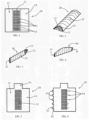
- Fig. 1 illustrates a sheet of a membrane 10 (hereafter called sheet and/or membrane) having a middle region 11 (between the dotted lines in Fig. 1 ) which can be perforated with several holes 12 and two side regions 13, 14 on each side of the middle region.
- the middle region 11 doesn't have to be at the middle of the sheet.
- the side regions 13, 14 can be not perforated.
- the side regions can include perforations with a diameter up to 5 microns and/or up to 10 microns and/or up to 15 microns and/or up to 20 microns and/or up to 25 microns and/or up to 30 microns so the diameter of largest hole in the side regions 13, 14 can be 5 microns or 10 microns or 15 microns or 20 microns or 25 microns or 30 microns.
- the side regions 13, 14 and the middle region 11 can have several types of holes with different dimensions and different shapes.
- the sheet 10 can be folded and/or rolled so a first side region 13 can be placed over the middle region 11 and a second side region 14 can be placed over the first side region 13.
- This folding and/or rolling of the sheet membrane 10 can create a tube like structure 20 as illustrated in Fig. 2 .
- the tube like structure 20 can have a middle perforated region 11 on one side of the tube 20 and two layers of membrane 13, 14 (the first and second side regions) on the other side of the tube 20, forming a soft tissue blocking region 21 of the tube 20.
- the folding can be along the folding lines 15.
- the folding can be assisted by placing a stick having a width like the width of the middle region, between the folding lines 15.
- the stick can be place on the middle region 11 and the side regions 13, 14 folded on the stick.
- the folding line 15 can include perforations and/or small slots having length of 0.5-3 mm or 1-2 mm or more than 3 mm.
- the folding lines 15 can include places having thinner width, like an imprint and/or an embossing in the membrane 11 along the folding lines 15 having length of 0.5-3 mm or 1-2 mm or more than 3 mm. These slots or embossing will enable easy folding of the membrane 11 along the folding lines 15.
- the second side region 14 can be connected to the first side region 13 and/or to the middle region 11 so the tube 20 keeps its tube structure and to prevent unfolding of the sheet membrane 10.
- the connection between the regions can be for example by suturing and/or gluing with biocompatible sutures/glues.
- the connection between the regions can be also by pressure and/or heat.
- the tube doesn't have to be oval and can have any other morphology.
- the glue mentioned above and later can be a polymer and/or hydrogel which polymerize under radiation during the sterilization process as described in international application No. WO 2015/107502 to Bioteck S.P.A. .
- the glue can be a flexible glue to keep the bag flexible so it will easily adapt to the bone morphology.
- the glue can be placed with intervals and/or only in several points so as to keep the flexibility of the bag.
- the tube 20 can be closed at one edge 31 of the tube to form a container 30 as illustrated in Fig. 3 .
- the closing can be for example by suturing and/or gluing with biocompatible sutures/glues.
- the closing of the tube edge 31 can be also by pressure and/or heat. It is possible to fold and/or roll the tube edge 31 before closing or to close it without folding and/or rolling.
- the device can be marketed to the surgeon as a sheet membrane 10, like the membrane illustrated in Fig. 1 with the middle region that can be perforated and the side regions 13, 14, and the surgeon will fold and/or roll and connect the side regions 13, 14 to form the tube 20 as illustrated in Fig. 2 . Then the surgeon can close one edge 31 of the tube 20 to form the container 30 like the container illustrated in Fig. 3 .
- the device can be marketed to the surgeon as a tube 20, like the tube illustrated in Fig. 2 . Then the surgeon can close one edge 31 to form the container 30 like the container illustrated in Fig. 3 .
- the device can be marketed to the surgeon already as a container 30, like the container illustrated in Fig. 3 .
- the container 30 can be filled with bone augmenting material. It can be filled with several bone augmenting materials, having different properties and with any combination of bone augmenting materials and/or any combination of a bone augmenting material and other materials like for example carriers, gels, polymers and hydrogels.
- the container 30 can be filled for example with a slow resorbable and/or a non-resorbable bone augmenting material together with a fast resorbable material.
- the container can be filled for example with small particle of bone augmenting material having for example size of less than 200 microns and/or size of 200-600 microns and/or size of 500-1000 microns.
- the container can be filled in addition or only, for example, with large particle bone augmenting material having for example size of more than 600 microns and/or size of 1000-2000 microns and/or size of more than 2000 microns.
- the container can be filled for example with particles and gels.
- the middle perforated region can have holes 12 which are large enough to allow bone tissue growth through these holes.
- the diameter of the holes can be larger than 10 microns preferably larger than 50 microns and/or larger than 100 microns and/or larger than 500 microns and/or larger than 1000 microns. The larger the holes the faster the bone regeneration.
- the diameter of the holes can be 500-2000 microns and/or 1000-1800 microns or larger than 2000 microns.
- the holes 12 can be circular or to have any other shape.
- the holes 12 can occupy at least 30 percent of the surface of the middle perforated region 11.
- the holes 12 occupy at least 50 percent of the surface of the middle perforated region 11 and/or at least 70 percent of the surface of the middle perforated region 11 and/or at least 90 percent of the of the surface of the middle perforated region.
- the middle region can have 2-10 holes and/or 10-20 holes and/or 20-50 holes and/or 50-70 holes and/or 70-100 holes and/or 100-130 holes and/or more than 130 holes.
- the number of holes can be determined according to the size of the middle region.
- the middle region can have 2-5 holes per cm 2 and/or 5-10 holes per cm 2 and/or 1-15 holes per cm 2 and/or 15-20 holes per cm 2 and/or 20-25 holes per cm 2 and/or more than 25 holes per cm 2.
- the middle perforated region 11 can have holes 12 which are sized according to the bone augmenting material. For example, according to the size of the particles of the bone augmenting material and/or according to the viscosity and/or fluidity of the bone augmenting material.
- the diameter of the holes 12 can be less than the diameter of part of the particles of the bone augmenting material and/or less than the diameter of the majority of the particles of the bone augmenting material and/or less than the diameter of all the particles of the bone augmenting material.
- the holes 12 can be larger than the diameter of the bone augmenting particles.
- the holes 12 can be larger than the diameter of the bone augmenting particles while the bone augmenting particles are inside a flowable surrounding, for example saline and/or a material that includes saline and/or blood and/or gel and/or collagen.
- the filling of the container 30 can be done by pouring the bone augmenting material inside the container and/or using a spoon like device and/or using a syringe, a rigid tube, a funnel, a stick and/or any other device that can be inserted inside the container 30.
- the container 30 can be closed at the second edge 41 of the container (the container's opening through which the bone augmenting was filled) to form a closed container 40 as illustrated in Fig. 4 .
- the closing can be for example by suturing and/or gluing with biocompatible sutures/glues.
- the closing of the container's opening can be also by pressure and/or heat. It is possible to fold and/or roll the container edge 41 before closing or to close it without folding and/or rolling.
- the container 40 can be marketed already filled with the bone augmenting material as illustrated in Fig. 4 or to be marketed as an open container 30 as illustrated in Fig. 3 to be filled with bone augmenting material and close by the surgeon.
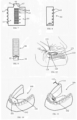
- the sheet and/or membrane 10 can include an edge closing extension 51 adjacent the middle/perforated region as illustrated in Fig. 5 .
- This edge closing extension 51 can be used to enable easy closure of one side of the container.
- the sheet and/or membrane 10 can be folded and/or rolled so the first side region 13 can be placed over the middle region 11, then the edge closing extension 51 can be folded and/or rolled and placed over the first side region 13, then the second side region 14 can be placed over the first side region 13 and the edge closing extension 51.
- This folding and/or rolling of the sheet and/or membrane and the edge closing extension 51 can create a container 30 as illustrated in Fig. 3 .
- the container 30 having the middle/perforated region 11 on one side of the container and two layers of membrane (the first and second side regions 13, 14) along at least part of the other side of the container forming the soft tissue blocking region 21. Adjacent the edge closing extension 51 there are three layers of membrane (the first and second side regions 13, 14 and the edge closing extension 51) along part of the soft tissue blocking region.
- edge closing extension 51 is folded over the middle perforated region, and the first and second side regions 13, 14 are placed over the edge closing extension 51. It is also possible that the edge closing extension 51 is folded over the first and second side regions 13, 14.
- the sequence and order of placing the various elements of the membrane 10 one on top of the other can be changed according to manufacturing preferences. However, if the closing extension 51 is short, it will be easier to stabilize the bag 30 while the closing extension 51 is between the side regions 13, 14.
- the membrane 10 can have along at least part of its borders connecting extensions 61 as illustrated in Fig. 6 having connecting extensions 61 extending from one side region 13.
- the connecting extensions 61 can have a constant width or have an arrow shape or any other shape in which the width of the connecting extension 61 is not constant.
- the connecting extensions 61 can have a neck portion 62 and an anchoring portion 63 which is wider than the neck portion 62.
- the neck portion 62 of the connecting extension 61 being closer to the center of the membrane 10.
- the membrane 10 can have slots 64 so at least part of the connecting extensions 61 can be inserted through the slots 64.
- the length of the slots 64 can be compatible with the width of the neck portion 62 and less than the width of the anchoring portion 63 of the connecting extension 61, so after the insertion of the anchoring portion 63 through the slot 64, the anchoring portion 63 resist passing back through the slot 64 without being folded.
- the slots 64 can be along the folding lines 15 so as to assist also with the folding of the membrane 10.
- the slots 64 can be also displaced from the folding lines 15.
- the membrane can have two adjacent slots 64, 65 as illustrated in Fig. 7 so when the connecting extension 61 is passed through both adjacent slots 64, 65 the anchoring portion 63 will be outside the container 80 as illustrated in Fig. 8 .
- the closing extension 51 can have also a slot 66 or two slots 66, 67 that can be, after folding, above the slots 64, 65 in the side region 14 so the connecting extension 61 can pass through the slots 64, 65 in the side region 14 and also through the slots 66, 67 in the closing extension 51, to better stabilize the bag.
- the length of the connecting extension 61 can be 1-20 mm or 2-10 mm or 3-7 mm.
- the membrane 10 can have more than one connecting extension or 2-10 or 3-7 connecting extensions.
- the distance between the connecting extensions 61 can be 2-25 mm or 3-15 mm or 5-10 mm.
- the connecting extensions 61 can be along both side regions 13, 14 and both side regions 13, 14 can have slots 64, 65 so each side region can be connected to the other side region. Slots can be at the middle region 11 and can be on both sides of the middle region 11.
- the edge closing extension 51 can have one or more connecting extensions 61 and the first side region 13 and/or the second side region 14 can have one or more slots to fixate the edge closing extension 51 to at least one of the side region (13, 14) in a similar manner as the first side region 13 being connected to the second side region 14.
- the second side region 14 can be connected to the first side region 13 and/or to the middle region 11 and/or the edge closing extension 51, so the container 80 keeps its structure and to prevent unfolding of the membrane 10.
- the connection between the regions of the membrane 10 can be in any manner.
- the container 90 can have a second edge closing extension 91 adjacent the opening of the container 92 as illustrated in Fig. 9 to allow easy closure of the opening 92 of the container 90 after filling the container 90 with the bone augmenting material.
- the second edge closing extension 91 can be folded and/or rolled inside the container 90 or above the second side region 14 or between the first side region 13 and the second side region 14.
- the membrane 10, the regions of the membrane 11, 13, 14, 51, 91, the connecting extensions 61 and the container 90 can have variable sizes and shapes, according to the bone deficiency needs to be regenerated.
- the membrane 10 can be for example rectangular with length of more than 60 mm or 40-60 mm or 20-40 mm or 4-20 mm or 5-17 mm and width of more than 60 mm or 40-60 mm or 20-40 mm or 4-20 mm or 5-17 mm and any combination of length and width.
- the container can have length of more than 60 mm or 40-60 mm or 20-40 mm or 4-20 mm or 5-17 mm.
- the width of the container can be more than 60 mm or 40-60 mm or 20-40 mm or 4-20 mm or 5-17 mm.
- the length of the container for regenerating a region of about 3 missing teeth can be 20-45 mm and the width of the container can be 7-20 mm.
- the length of the container for regenerating a region of about 1 missing teeth can be 5-15 mm and the width of the container can be 7-20 mm.
- the closing extensions 51, 91 can have several shapes and several dimensions.
- the length of the closing extensions 51, 91 (along a line connecting the openings of the tube) can be 3-20 mm or 5-18mm, or 10-15mm or 7-10 mm or longer than 20 mm.
- the width of the closing extensions 51, 91 can be the same as the width of the middle region 11 or can be wider or narrower by 0.5-4 mm or 1-3 mm than the width of the middle region 11.
- the closing extensions can have a rectangular shape and/or have rounded corners and/or any other shape.
- the middle region 11 and the side regions 13, 14 can have variable portions along the membrane 10.
- the middle region 11 and the side regions 13, 14 can be a third of the width of the membrane 10.
- the middle region 11 can be narrower than the side regions 13, 14.
- the side regions 13, 14 can have substantially the same width or one side region can have larger width than the other side region.
- the second side region can cover completely the first side region or can cover only part of the first side region.
- the first side region can cover completely the middle region or can cover only part of the middle region.
- the second side region can cover completely the middle region or can cover only part of the middle region.
- the width of the middle region 11 can be larger than 20 mm or 3-25 mm or 5-20 mm or 7-16 mm.
- the middle region 11 can be perforated with several holes 12.
- the holes 12 can be along only part of the middle region 11.
- the edges of the middle region 11 along its width, towards the closing extension s 51, 91, can be without holes for 1-10 mm or 3-7 mm or 1-3 mm.
- the edges of the middle region 11 along its length, towards the first and/or second side regions 13, 14, can be without holes for 1-10 mm or 3-7 mm or 1-3 mm.
- the middle region 11 can be without holes and to be bio-dissipative.
- the middle region 11 can bio-dissipate faster than the side regions 13, 14, which can be also non bio-dissipative.
- the middle region 11 can be bio-dissipative and/or to have holes. Any combination of degree of bio-dissipatedness and perforations can be.
- the holes can have various combinations of sizes.
- the middle region can have combination of large holes of more than 1000 microns with small holes of less than 500 microns.
- the bone augmenting material can have various combinations of sizes.
- the bone augmenting can have combination of large particles of more than 1000 microns with small particles of less than 500 microns.
- the combination of bone particles can be used with a container having a compatible combination of holes' sizes.
- the bone augmenting material can have at least two bone augmenting materials having different times of resorption.
- a fast bio-dissipative material that will allow fast ingrowth of blood vessels and bone forming cells
- a slowly bio-dissipative and/or non resorbable bone augmenting material that will keep the volume for a long period of time.
- the slowly bio-dissipative material can be for example a bovine mineral (like Bio-Oss from Geistlich, Switezerland) that remains in the body for several years.
- a slowly bio-dissipative material can be used for example also for aesthetic treatments without bone regeneration or together with bone regeneration.
- a container filled with slowly bio-dissipative material can be placed along the buccal aspect of the anterior maxillary alveolar ridge to increase the volume of the tissue and advance the position of the upper lip. This advance of the upper lip can eliminate wrinkles and improve the aesthetic smile and appearance.
- a container filled with slowly bio-dissipative material can be placed for example adjacent the zigomatic bone to advance the cheek bones. The exact position of the container can be decided for each patient according to its individual needs and according to the individual deficiency that needs to be filled.
- the surgeon can prepare and insert the container through a subperiosteal tunnel or to raise a mucoperiosteal flap and suture the mucoperiosteal flap over the container.
- the middle region can be placed towards the bone and the side regions towards the periosteal tissue.
- the jaw bone can be perforated before the placement of the container adjacent the jaw bone.
- the preparation of the subperiosteal tunnel and/or the insertion of the container inside the tunnel can damage the mental nerve and/or its branches which are located on the buccal side of lower jaw.
- At least part of the subperiosteal tunnel is prepared from the lingual side of the lower jaw as illustrated in Figs. 10 and 11 .
- the opening of the tunnel can be from the lingual side of the mandible (the lower jaw) 100 and in many cases from the anterior lingual side.
- the lingual opening 102 can be done by raising a lingual mucoperiosteal flap 101 below the anterior teeth 103 as illustrated in Fig. 10 .
- the lingual opening 102 can be along any segment of the lingual aspect of the mandible 100 and to cross the midline of the mandible.
- the insertion of the container 110 can be through the lingual opening 102 as illustrated in Fig. 11 . In this manner the mental nerve is not damaged.
- the container 110 After the insertion of the container 110 it can be placed on top of the alveolar ridge to vertically augment the lower alveolar ridge and/or to be inserted and placed at the buccal and/or lingual aspects of the lower jaw bone to horizontally augment the alveolar ridge. To reach the buccal aspect, the container 110 can be pushed from the lingual side over the alveolar crest and down to the buccal side.
- a suture 111 which is connected to a needle 112, and to insert the needle 112 and the suture 111 inside the tunnel and to pass the needle 112 and the suture 111 through the periosteal tissue to be outside the tunnel as illustrated in Fig. 11 .
- the suture 111 can be sutured to the soft tissue so as to fixate the container, which is inside the tunnel.
- the suture 111 can be made from a bio-dissipative material.
- the lingual opening 102 can be at the lingual anterior region of the lower jaw 100 and the container being placed at the posterior region of the lower jaw as illustrated in Fig. 11 .
- the lingual opening can be at the lingual posterior region of the lower jaw and the container being placed at the anterior region of the lower jaw.
- the location of the lingual opening and the location of the container can be determined individually for each patient. There are advantages if the lingual opening is not above the location of the container, because if there is a later opening of the sutures at the lingual opening, it is not above the container and the chances for infection of the container are reduced. There are also advantages that the periosteal tissue above the container is not cut and sutured so the blood supply to the tissue is not damaged and therefore reducing the chances for exposure of the container.
- the container (or bag or pouch) can be inserted inside the tunnel while being inside a dedicated syringe and then injecting the container to its place. This way the membrane of the container is not touching the surrounding tissues during the insertion of the container and the membrane of the container is not damaged.
- the container is inserted inside a cover and/or an envelope and/or a sleeve before being inserted inside the tunnel and after the insertion of the container the cover and/or the envelope and/or the sleeve is removed leaving the container inside the tunnel. This way the membrane of the container is not touching the surrounding tissues during the insertion of the container and the membrane of the container is not damaged.
- the cover and/or envelope and/or sleeve can be closed at one side to form a bag like cover with one opening. If the container is connected to a suture 111, then the suture exit the cover from the open side of the cover while the closed side of the cover is at the opposite side. In the embodiment of Figs. 10 and 11 the closed side of the cover will be towards the anterior of the mandible.
- the cover can be flexible and can be made, for example, from rubber, nylon, silicon and any other materials and combinations thereof. It will be advantageous if the cover will be transparent so the surgeon will know where the perforated side of the container is. It will be advantageous if the cover bag will be made from biocompatible materials.
- the container can be also fixated using a bone screw like a GBR membrane fixating screw and/or fixated by a tack or a pin like a GBR membrane fixating tack (for example, titan pin set from Botiss, Germany).
- the fixating inside the tunnel can be by using a curved tack delivery device (for example the AutoTac membrane fixation kit from BioHorizons U.S.).
- the bag can have an extension for fixation through which the bone screw and/or the bone tack will be inserted.
- the extension for fixation can be perforated to enable the surgeon to see the bone while inserting the screw and/or the tack.
- the perforated extension for fixation can be part of the perforated middle region 11 of the sheet 10 illustrated in Figs 1, 5, 6 and 7 after the preparing a bag, which is shorter than the perforated middle region.
- the container can be stabilized by more than one tack or screw.
- more than one tack or screw it is possible to use two tacks at the side of the bag which is close to the opening of the subperiosteal tunnel.
- the anterior (or mesial) side of the container can be fixated with one tack adjacent the anterior buccal corner of the container and a second tack adjacent the anterior lingual corner of the container.
- fixating screw and/or a tack and/or a pin it is also possible to insert through the gums at the posterior (or distal) region a fixating screw and/or a tack and/or a pin to stabilize the posterior region of the container. It is possible to perform a small cut in the posterior region of gums before the insertion of the fixating screw and/or the tack to enable the surgeon to see the container before inserting the fixating screw and/or the tack and/or to see the bone when drilling a hole for the fixating screw and/or the tack.
- the fixating screw and/or the tack can protrude through the gums to the oral cavity, so the gums will heal around the fixating screw and/or the tack.
- the container can be used in an open sinus lift procedure called also open sinus augmentation procedure. After opening a lateral window in the lateral wall of the maxillary sinus and elevating the Schneiderian membrane, the container can be inserted through the opening in the lateral wall and to be placed above the floor of the maxillary sinus and below the elevated Schneiderian membrane. The container can be inserted already filled with bone augmenting material and/or can be filled after being inside the maxillary sinus. The container can be placed while the side with the two membranes will face the opening in the lateral wall of the maxillary sinus and/or the Schneiderian membrane and/or a tear in the Schneiderian membrane.
- the container can be inserted inside the sinus in case when the Schneiderian is intact and wasn't torn during its elevation.
- the container can be inserted inside the sinus in cases when the Schneiderian membrane was torn during its elevation and/or in cases when the Schneiderian was damage and/or absent before the beginning of the surgical procedure. In cases when the Schneiderian membrane is torn and/or absent it is recommended to fixate the container to be in contact with the floor of the maxillary sinus.
- There are several options to fixate the container For example, a dental implant and/or several dental implants can be inserted through the maxillary alveolar ridge and the floor of the maxillary sinus and inside the container.
- the container can be fixated using screws which are used to fixate bone blocks.
- the container can be fixated using screws or tacks which are used to fixated GBR membranes, while the screw and/or the tacks can be inserted from inside the sinus towards the oral cavity and/or from the oral cavity towards inside the sinus.
- the container can be fixated using sutures and/or wires.
- a fixating hole 121 and/or several fixating holes can be drilled adjacent to the opening 122 in the lateral wall 123 of the maxillary sinus.
- a suture 124 can be connected to the container 125 (the container is illustrated in Fig. 12 for clarification purposes although the container is inside the sinus and its boundaries usually can't be seen in this lateral view. In this view only the part of the container 125 which is adjacent the opening 122 can be seen) and passed through the fixating hole 121.
- the suture 124 can be passed through the opening 122 in the lateral wall of the maxillary.
- the suture can be tied and therefore fixating the container and keeping it in contact with the floor 126 of the maxillary sinus (illustrated in a dotted line in Fig. 12 , the floor of the maxillary sinus usually can't be seen in this lateral view).
- the container can have a side opening at one of it sides - the middle region and/or the soft tissue blocking region, to enable filling the container.
- This filling can be in addition to filling through an opening at the edge of the bag, as described above.
- This filling through a side opening can be instead of filling through an opening at the edge of the bag.
- the bag can be marketed closed at its both edges and filled through the side opening.
- the side opening can be at the soft tissue blocking region so the first (inner) sheet (or the first side region) has an opening which can be accessible through the second sheet (or the second side region).
- the side opening can be covered by a retractable and/or movable piece of membrane - a retractable cover, that is attached to the container and can be moved to reveal the opening to allow insertion of a bone material inside the bag and then the retractable cover can be returned to its place to close the side opening.
- the side opening in the soft tissue blocking region can be covered by two retractable and/or movable pieces of membrane - retractable covers.
- the second retractable cover can be larger than the first retractable cover so the borders of the second retractable cover can be over the first sheet around the borders of the first retractable cover, so the first retractable cover being partially or fully cover by the second retractable cover. This configuration can be more efficient in closing the side opening to prevent leakage of bone material from the container through the side opening.
- the first and second retractable covers can be designed to be retracted to different direction.
- the first retractable cover can be connected to the first sheet close to the right border of the container and to be retracted in the right direction
- the second retractable cover can be connected to the second sheet close to the left border of the container and to be retracted in the left direction.
- the first retractable cover can be connected to the first sheet closer to a first edge of the container and to be retracted towards the first edge
- the second retractable cover can be connected to the second sheet closer to the second edge of the container and to be retracted towards the second edge.
- the first sheet can have also a slot between the opening in the first sheet and the border of the first sheet so the second retractable cover will be inserted through this slot to better fixate the second retractable cover to prevent its dislocation during insertion of the container inside a subperiosteal tunnel.
- the second and/or the first retractable covers can be sutured and/or glued to the container for improved fixation.
- the retractable covers can have variable shapes for example, circular, oval, elliptic, rectangular and/or any tongue like shape which is connected at one side to the container.
- the side opening can be adjacent to the center of the container or adjacent to the edges of the container.
- the side opening being adjacent to one of the edges of the container. In this configuration, when both edges are already closed, the surgeon doesn't need to close the bag after filling through the side opening.
- the side opening being adjacent to center of the container.
- One edge can be open to allow initial filling through an opening in the edge of the container and after the insertion inside the sinus the container can be filled through the side opening. If both edges of the container are closed, the initial filling and/or the filling after the insertion of the container inside the maxillary sinus can be through the side opening.
- the width of the middle region is smaller than the width of the side regions so the soft tissue blocking region is larger than the middle region and it is facing the Schneiderian membrane and the opening 122 in maxillary wall sinus 123 while the middle region is facing the floor 126 of the maxillary sinus.
- the width of the middle region is larger than the width of the side regions so the soft tissue blocking region is smaller than the middle region and it is facing the opening 122 in maxillary wall sinus 123 while the middle region is facing the floor 126 of the maxillary sinus and the Schneiderian membrane.
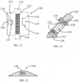
- Fig. 13 illustrates an embodiment of a sheet and/or a membrane for preparing a container with a side opening.
- the sheet 130 has a middle perforated region 131 with several holes, a first side region 133, a second side region 134, a first closing extension 135 and a second closing extension 136.
- the sheet can include also connecting extensions and compatible slots as described above and not illustrated in Fig. 13 .
- the first side region 133 can include a non-linear slot or several connected slots 137 surrounding partially a piece of the first side region 133 so this piece of the first side region 133 can be elevated from the first side region 133 while being connected to the first side region 133 to form a first retractable cover 138.
- the second side region 134 can include a non-linear slot or several connected slots 141 covering partially a piece of the second side region 134 so this piece of the second side region 134 can be elevated from the second side region 134 while being connected to the second side region 134 to form a second retractable cover 139.
- the first side region 133 can have also a cover fixating slot 140 to fixate the second retractable cover 139 after preparing a container from the sheet 130 and filling the container with bone augmenting material.
- Fig. 14 illustrates a container 142 prepared from the membrane or sheet 130 of Fig. 13 .
- one edge opening 143 is still open and the second closing extension 136 is prepared to close the edge opening 143.
- the second side region 134 cover the first side region 133 to form the soft tissue blocking region 144.
- the first retractable cover 138 and the second retractable cover 139 being retracted to reveal the side opening 145.
- the middle perforated region 131 can be seen through the edge opening 143 and through the side opening 145.
- Fig. 15 illustrates the container 150 after being filled and the edge opening 143 of the container of Fig. 14 being closed and the side opening 145 of the container of Fig. 14 being covered by the second retractable cover 139.
- the side opening 145 can be also covered by the first retractable cover 138 which is not illustrated in Fig. 15 for being covered by the second retractable cover 139. If the container is for use during a sinus lift procedure the side opening can be placed to be accessible through the opening in the maxillary sinus wall.
- the container can be fixated to the floor of the maxillary sinus and/or the lateral wall of the maxillary sinus as described above, for example by using a fixating hole and sutures and/or wires. It is also possible to retract one of the retractable covers 138, 139 while leaving the other retractable cover over and closing the side opening 145. The retracted cover can be fixated to the floor of the maxillary sinus and/or the lateral wall of the maxillary sinus, for example by tacks. It is also possible to close the side openings of the container 140 of Fig. 14 without using the closing extensions 135, 136 of Fig. 13 . The edges can be closed as explained above, for example by suturing. In this embodiment the closing extensions can be used to fixate the container, for example by tacks inserted through the closing extensions and the lateral wall 123 of the sinus.
- the container can be used also for treatment of other tissues.
- a similar container having holes one one side can be filled with chondrocytes and place in the knee so the perforated side is towards the joint and the blocking region is towards the skin to encourage regeneration of cartilage. Similar treatment can be done in the in other joints.
- the container can be placed between two tissues or organs and filled with medications that are intended for the treatment of one tissue, so the perforated side of the container will face the tissue that requires the treatment without influencing the second tissue or organ.
- the sheet can be made from a materials that blocks radiation and the container can be placed between two tissues or organs and filled with a radiation emitting material that is intended for the treatment of malignancy in one tissue, so the perforated side of the container will face the tissue that requires the treatment without influencing and damaging the second tissue and/or organ.
- the sheet can be made at least partially from metal foils.
- the sheet can be made at least partially from one of the materials of guided bone regeneration membranes as mentioned above, like collagen and molecules and/or particles and/or fibers of radiation blocking material.
- the materials of the sheet can be bio-dissipative while the radiation blocking particles or fibers will remain without damaging the surrounding organs.
- Such a container can be placed for example between the prostate and the rectum while treating the prostate and protecting the rectum.
Description
- The present invention relates to devices for tissue augmentation and/or bone augmentation. Methods of producing the devices and methods of using the devices of the invention are also disclosed but do not form part of the claimed invention. The devices can be used also for other treatments, for example directional release of medications and/or radiation.
- Treatment of edentulous patients with dental implants called also osseointegrated fixtures, which are made mainly of titanium and/or zirconium, is a well known procedure in the art. The procedure includes installing a dental implant in the alveolar bone of an at least partially edentulous jaw. Usually several months are required for proper healing after implant installation. After healing, an abutment is installed on the (called also "coronal") portion of the dental implant. After several weeks, an artificial tooth may be mounted on the abutment and the procedure is complete. It is also possible in some cases to connect the abutment and/or the crown and/or the bridge and/or the denture and/or a dolder bar and/or any dental element to the dental implant much earlier and even in the same day.
- Installation of implants requires sufficient alveolar bone, generally about 10 mm height and 7 mm width.
- When a tooth is removed, the alveolar bone is gradually resorbed because of the absence of stimulus of ossification-inducing pressure from the teeth. As the resorption process advances, the size of the bone gets reduced, i.e. the bone on which the dental roots are positioned - the alveolar ridge start shrinking.
- The absence of just one tooth can cause modifications throughout the dental arch and even prompt a possible softening (loss of insertion) which may cause the loss of other teeth. The absence of several teeth aggravates the problem. Bone loss may finally modify the patient's appearance and, depending on the loss, may make him incapable of receiving bridges, implants or even dentures.
- It is then necessary to carry out several surgical operations to reconstruct the alveolar ridge of the maxilla (called also the maxillary bone) or mandible (called also mandibular bone or mandibular).
- Although these methods of surgical reconstruction have been successfully performed, this type of operation has had drawbacks. Certain methods have involved opening the mucoperiosteal tissue called also periosteal tissue and/or gums and/or gingiva along the entire length of the atrophic alveolar ridge and then placing a bone graft material and a membrane on top of the graft and then suturing the delicate mucoperiosteal tissue back together to cover the membrane. The role of the membrane is to maintain the bone graft in its place and to prevent the mucoepithelium from growing into the graft and interfering with the process of bone regeneration. This surgical operation has drawbacks and usually only limited amount of bone regeneration can be achieved.
-
U.S. patent No. 7,749,267 to Karmon andU.S. patent No. 8,622,739 to Karmon disclose devices and methods to overcome some of these drawbacks. Karmon discloses a bag to be placed between the bone and the periosteal tissue, which can be filled with bone augmenting material. The bag can be perforated on the side facing the bone while the side facing the periosteal tissue can be made from a guided bone regeneration membrane and can have different properties than the perforated side.U.S. patent application No. 20150320463 to Karmon disclose devices and methods to treat fractures with bags that can be filled with bone augmenting material and can have a perforated side. - However preparation of such a bag is not trivial, especially when it is made from biological material like collagen or pericardium.
U.S. patent application No. 2006287732 A1 to Pezeshkian alex discloses perforated bags requiring many sutures and time consuming procedures to prepare the bags.EP 3419563 A1 to Warsaw Orthopedic Inc. [US] discloses an envelope for bone materials made mainly for spine surgeries.US 20140277570 A1 to Behnam Keyvan et al . discloses a carrier made from bone to retain bone material. The insertion of the bag inside a subperiosteal tunnel is not trivial either, especially in the posterior region of lower jaw, adjacent the mental nerve, which can be damaged during the insertion of the bag. - Therefore there is a need for better devices and methods for producing the bags and/or containers and methods that will allow safer insertion of the bags inside a subperiosteal tunnel, if a subperiosteal tunnel is used.
- The present invention provides devices to perform tissue regeneration. The following embodiments will focus on bone regeneration in the jaws, however similar devices can be used for other bones and/or tissues in the body. For example the bags can be used for regeneration of cartilage tissue in the knee or in other joints.
- One of the inventions is a bag having one layer membrane on one side and two layers of a guided bone regeneration membrane on the opposite side. The side with one layer can be perforated with holes that allow bone tissue ingrowth. The bag can be completely bioresorbable. The side with the one layer can be made from other materials than the side with the two membranes. The side with the one layer can be made to be resorbed faster than the side with the two layers, however both sides can be fully and/or partially non-resorbable. The bag can be filled with a material that promotes bone growth. The bag can be placed in the jaw so the side with the one layer will be placed towards the bone and side with the two layers towards the gums. The side with the two layers can be such that it prevents soft tissue ingrowth inside the bag that will interfere with bone regeneration process.
- Other objects and features of the present invention will become apparent in the following detailed description when taken in connection with the accompanying drawings which disclose several embodiments of the invention. It is to be understood that the drawings are designed for the purpose of illustration only and are not intended as a definition of the limits of the invention.
- It is also to be understood that any combination of the embodiments described hereafter can be used although these combinations are not explicitly described. The number of possible combinations of different elements in different relations to each other and the number of options of using the devices is enormous. Therefore only several embodiments are described and illustrated.
- The present invention provides a number of novel features, each of which is believed to be of patentable significance, and which can be combined in various combinations. A selection of the combinations will be described below, and other possible combinations will be clear to one ordinarily skilled in the art on the basis of this description. All features described below in the context of one exemplary embodiment of the present invention should be understood as being equally applicable to other embodiments except where the features are clearly incompatible or it is explicitly stated otherwise.
- Thus, according to the teachings of the present invention there is provided a device for treating patients in need for tissue regeneration comprising: a guided regeneration membrane, the membrane comprising: a perforated region having several holes with a diameter of more than 30 microns; a first side region located at the left side of the perforated region and extending from a left edge of the membrane to a first folding line between the perforated region and the first side region; and a second side region located at the right side of the perforated region and extending from a right edge of the membrane to a second folding line between the perforated region and the second side region, wherein the first side region has no pores, or has pores such that the largest pore in the first side region has a diameter of up to 30 microns, wherein the first side region is configured to be folded along the first folding line so as to cover the perforated region, and wherein the second side region is configured to be folded along the second folding line so as to cover the first side region so the right edge of the membrane is adjacent to the first folding line, wherein the first and second side regions form, when folded, a soft tissue blocking region with two parallel layers covering at least a majority of the perforated region, the soft tissue blocking region has no pores or has pores such that the largest pore in the soft tissue blocking region has a diameter of up to 30 microns.
- Further features and embodiments of the present invention are defined in the appended dependent claims.
- The invention is herein described, by way of example only, with reference to the accompanying drawings, wherein:
-
FIG. 1 is a perspective view illustrating an embodiment of a sheet having a perforated region. -
FIG. 2 is a perspective view illustrating an embodiment of a tube formed after folding and/or rolling the sheet ofFig. 1 . -
FIG. 3 is a perspective view illustrating an embodiment of a bag formed after closing one edge of the tube ofFig. 2 while the other edge is open. -
FIG. 4 is a perspective view illustrating an embodiment of the bag ofFig. 3 after the bag being filled and the other edge of the bag being closed. -
FIG. 5 is a perspective view illustrating an embodiment of a sheet having a perforated region and edge closing extension to allow easy closure of the edge of the tube, formed after folding and/or rolling the sheet. -
FIG. 6 is a perspective view illustrating an embodiment of a sheet having a perforated region, edge closing extension to allow easy closure of the edge of the tube formed after folding and/or rolling the sheet, connecting extensions and a slot for each connecting extension to connect the two side regions of the sheet. -
FIG. 7 is a perspective view illustrating an embodiment of a sheet having a perforated region, edge closing extension to allow easy closure of the edge of the tube, formed after folding and/or rolling the sheet, connecting extensions and two slots for each connecting extension to connect the two side regions of the sheet. -
FIG. 8 is a perspective view illustrating an embodiment of a bag formed after folding and/or rolling the sheet ofFig. 7 , closing one edge with the edge closing extension and connecting the side regions of the sheet using the connecting extensions inserted through the two slots. -
FIG. 9 is a perspective view illustrating an embodiment of a bag having one edge closed and a second edge closing extension to allow easy closure of the second edge of the bag after filling the bag. -
FIG. 10 is a perspective view illustrating the mandible in which the anterior lingual mucoperiosteal tissue was detached from the jaw bone to create a lingual opening to a subperiosteal tunnel. -
FIG. 11 is a perspective view illustrating the mandible ofFig. 10 in which a bag is inserted through the anterior lingual opening inside the subperiosteal tunnel towards the posterior region of the jaw bone. -
FIG. 12 is a lateral view illustrating fixating the bag inside the maxillary sinus during an open sinus lift procedure, while using sutures and/or wires and additional fixating holes. -
Fig. 13 is a perspective view illustrating an embodiment of a sheet having a perforated region, closing extensions and retractable covers to cover a side opening. -
FIG. 14 is a perspective view illustrating an embodiment of a bag formed after folding and/or rolling the sheet ofFig. 13 . The bag has a side opening and an edge opening to allow filling of the bag. -
FIG. 15 is a perspective view illustrating an embodiment of the bag ofFig. 14 after the bag being filled and the edge opening closed and the side opening being covered by the two retractable covers. - Before turning to the features of the present invention in more detail, it will be useful to clarify certain terminology as will be used herein in the description and claims. Specifically, it should be noted that the present invention is useful in a wide range of applications in which living tissue is to be regenerated or treated. The term "living tissue" is used herein to refer to any living tissue including, but not limited to bone, an organ, tube, vessel, cavity, bone cavity or membrane, and interfaces between any two or more of the above. Where used within a single type of tissue, the typical application of the present invention is for regenerating the tissue inside the tissue. When used at a tissue interface, the invention is typically used to separate between tissues and/or treating only one tissue.
- It is noted that a large number of different types of materials are known which may be inserted within the body during a surgical procedure and which later dissipate, thereby avoiding the need for a separate surgical procedure for their removal. Such materials are properly referred to, depending upon the mechanism by which the material dissipates, as "resobable", "bioresorbable", "absorbable", "bioabsorbable", "degradable" or "biodegradable". Despite the differences between these different classes of materials, the aforementioned terminology is widely used interchangeably by medical professionals. Accordingly, and for conciseness of presentation, only one of these terms will generally be used in the following description, without implying the exclusion of the other classes of materials. Additionally, the phrase "bio-dissipative material" is used herein in the description and claims to refer generically to any and all materials which dissipate without requiring surgical removal, independent of which mechanisms such as dissolution, degradation, absorption and excretion take place. The actual choice of which type of materials to use may readily be made by one ordinarily skilled in the art.
- The bone can be regenerated by several biological mechanisms: Osteogenesis in which the bone augmenting material includes bone forming cells; Osteoinduction in which the bone augmenting material includes materials that induce cells to form bone or to differentiate to become bone forming cells; Osteoconduction in which the bone augmenting material provides a scaffold for bone forming cells; or Osteopromotion in which encouraging the biologic or mechanical environment of bone regeneration. The bone augmenting material can be an autograft, an allograft, a xenograft, an alloplast, a cytokine, a hormone, a growth factor, a physiologically acceptable drug, a biological modifier, a protein (for example Bone Morphogenetic Protein (like BMP-2, BMP-7)), an antigen, a cell chemotaxis stimulator material, a material inducing osteogenesis, an osteoinduction material, an osteoconduction material, a bioactive material, a bioresorbable material, a bioabsorbable material, a bio-dissipative material and any combination thereof. The bone augmenting material can include materials that occupy a space in the body for at least several weeks. These materials preferably encourage the tissue to grow inside the space occupied by the material. This is the principle function of most bone augmenting materials available on the market. The bone augmenting material can be entirely bio-dissipative. The bone augmenting material can be available in the market like hydroxyapatite, bovine mineral (i.e. Bio-Oss available from Geistlich, Switzerland), materials from other species, for example, equine origin materials, materials combining mineral and collagen (i.e. OX granules available from Bioteck SPA, Italy), demineralized frizzed dried bone allograft, synthetic materials like PLA or suspension of mineral particles (from various origins) in a liquid medium. The bone augmenting material can be also fully or partially not bio-dissipative, for example crystal hydroxyapatite. The bone augmenting material can include therapeutic materials.
- The bone augmenting material can be a biocompatible filling filing material that sets and becomes rigid inside the tissue. The biocompatible filling material can be a bio-dissipative material that contains materials assisting in the process of bone healing like bone cements, for example Skeletal Repair System (SRS) from Norian company, Healos from Orquest company, OsteoGenics and Orthovita's Orthocomp from Howmedical Leibinger company.
- Most bone augmenting materials are available as particles in the size of 200-2000 microns. To allow easy insertion, preferably the particles are mixed with a solution like saline, blood or biocompatible gels like cellulose, glycerol and/or hydrogel. The bone augmenting material can be high viscous gel like Dinagraft which is gelatinous allograft bone augmenting material and/or with bone cements calcium sulfate and/or calcium carbonate. Additionally, the phrase "augmenting material" is used herein in the description and claims to refer generically to any and all these materials and mechanisms and in all mediums and/or gels in which these materials are mixed with. The actual choice of which type of materials and/or combination of materials to use may readily be made by one ordinarily skilled in the art.
- Along the description sometimes the device is called "bag" and sometimes "container". Both terms refer to a device that can contain bone augmenting material. The "container" or "bag" can be also a pouch or cloth like pouch in all the embodiments.
- The term "anterior" means more towards the front and close to the lips. The term "posterior" mean more towards the back and close to the throat. The term "buccal" means the side towards the cheeks and lips. The term "lingual" means the side towards the tongue. The term "mesial" inside the mouth means in dentistry towards the location of central teeth along the dental arch. The term "distal" inside the mouth means in dentistry towards the location of posterior teeth along the dental arch.
- The term membrane means a sheet of material that can be made from variable materials in variable shapes and any combination of materials. The membrane preferably can be made from biocompatible materials. The membrane can be partially or completely bio-dissipative or can be completely non resorbable. The membrane can be made from artificial materials, for example polyglycolic acid (PGA) mesh, a high-molecular-weight linear polymer made by the ring opening polymerization of the purified glycolide monomer, e.g. polyglactin 910, i.e. polyglycolide co-galactide or/and PDS (another absorbable suture material) and/or cellulose which are bio-disipative or can be made from PTFE and/or ePTFE and/or Teflon which are not resorbable. The membrane can be made from autograft, allograft, xenograft and any combination thereof. For example the membrane can be made from collagen and/or cross-linked collagen. The membrane can be made from pericardium, peritoneum, vessels and other tissues and/or biological membranes. The membrane can have different thickness at different regions of the membrane. The membrane can have different stiffness and/or flexibility at different regions of the membrane. The membrane can have more than one layer and each layer can have different properties and/or can be made from different materials. The membrane can include a guided tissue regeneration membrane and/or guided bone regeneration membrane. Guided bone regeneration (GBR) membranes are used in dental implant dentistry to regenerate bone. The GBR membranes prevent the epithelial and connective tissue to penetrate the bone defect and interfere with the bone regeneration process. The membrane can be any combination of the above.
- When the bag is inserted inside a subperiosteal tunnel, there is an advantage to using a tear resistant membrane like a pericardium membrane, for example Jason membrane from Botiss (Germany) or like compressed collagen, for example Bio-Gide compress from Geistlich (Switzerland).
- Along the description sometimes the device and/or part of it is called "sheet" and sometimes "membrane". Both terms refer to a device and/or part of the device which can be used to form a bag. The sheet or membrane is usually flexible like a cloth or a fabric. The sheet or membrane can be cloth like ready to use or might requires hydration to become less stiff and more flexible like a fabric.
- Along the description holes and/or perforations are mentioned having different optional diameters. The use of the term "diameter" doesn't necessarily imply that the shape of the holes is round. The holes can have various shapes like ellipse and/or polygonal shapes for example square or hexagon and can have a non-regular or non-defined shape.
- The term mucoperiosteal tissue in the jaws can mean also gums and/or gingiva.
- Finally with respect to terminology, reference will be made to a flowable material that can be used to fill the containers and/or bags of the present invention. It should be noted that this flowable material may assume a wide range of compositions and consistencies, so long as the filling material may be inserted into the container. Thus, possible consistencies for the filling material include, but are not limited to, consistencies described as watery, viscous, gelatinous, moldable, waxen, particulate, and suspensions or mixtures combining any of the above. The filling material can be also any kind of a bone augmenting material described above, which can be a flowable material. The bone augmenting material can be a suspension of particles is a solution like saline. The bone augmenting material can be particles inside gel. The particles can be from any type of bone augmenting material motioned above and the gel can be from any type of bone augmenting material mentioned above. The gel can include collagen and/or any material encouraging bone formation.
- Turning now in detail to the drawings, which depict the presently preferred embodiments of the invention for the purpose of illustrating the practice thereof and not by way of limitation of the scope of the invention, and in which like reference characters refer to corresponding elements throughout the several views.
-
Fig. 1 , illustrates a sheet of a membrane 10 (hereafter called sheet and/or membrane) having a middle region 11 (between the dotted lines inFig. 1 ) which can be perforated withseveral holes 12 and twoside regions middle region 11 doesn't have to be at the middle of the sheet. Theside regions side regions side regions middle region 11 can have several types of holes with different dimensions and different shapes. Thesheet 10 can be folded and/or rolled so afirst side region 13 can be placed over themiddle region 11 and asecond side region 14 can be placed over thefirst side region 13. This folding and/or rolling of thesheet membrane 10 can create a tube likestructure 20 as illustrated inFig. 2 . The tube likestructure 20 can have a middleperforated region 11 on one side of thetube 20 and two layers ofmembrane 13, 14 (the first and second side regions) on the other side of thetube 20, forming a softtissue blocking region 21 of thetube 20. - The folding can be along the folding lines 15. The folding can be assisted by placing a stick having a width like the width of the middle region, between the folding lines 15. The stick can be place on the
middle region 11 and theside regions folding line 15 can include perforations and/or small slots having length of 0.5-3 mm or 1-2 mm or more than 3 mm. The folding lines 15 can include places having thinner width, like an imprint and/or an embossing in themembrane 11 along thefolding lines 15 having length of 0.5-3 mm or 1-2 mm or more than 3 mm. These slots or embossing will enable easy folding of themembrane 11 along the folding lines 15. - The
second side region 14 can be connected to thefirst side region 13 and/or to themiddle region 11 so thetube 20 keeps its tube structure and to prevent unfolding of thesheet membrane 10. The connection between the regions can be for example by suturing and/or gluing with biocompatible sutures/glues. The connection between the regions can be also by pressure and/or heat. - The tube doesn't have to be oval and can have any other morphology.
- The glue mentioned above and later can be a polymer and/or hydrogel which polymerize under radiation during the sterilization process as described in international application No.
WO 2015/107502 to Bioteck S.P.A. . - The glue can be a flexible glue to keep the bag flexible so it will easily adapt to the bone morphology. The glue can be placed with intervals and/or only in several points so as to keep the flexibility of the bag.
- The
tube 20 can be closed at oneedge 31 of the tube to form acontainer 30 as illustrated inFig. 3 . The closing can be for example by suturing and/or gluing with biocompatible sutures/glues. The closing of thetube edge 31 can be also by pressure and/or heat. It is possible to fold and/or roll thetube edge 31 before closing or to close it without folding and/or rolling. - The device can be marketed to the surgeon as a
sheet membrane 10, like the membrane illustrated inFig. 1 with the middle region that can be perforated and theside regions side regions tube 20 as illustrated inFig. 2 . Then the surgeon can close oneedge 31 of thetube 20 to form thecontainer 30 like the container illustrated inFig. 3 . - The device can be marketed to the surgeon as a
tube 20, like the tube illustrated inFig. 2 . Then the surgeon can close oneedge 31 to form thecontainer 30 like the container illustrated inFig. 3 . - The device can be marketed to the surgeon already as a
container 30, like the container illustrated inFig. 3 . - The
container 30 can be filled with bone augmenting material. It can be filled with several bone augmenting materials, having different properties and with any combination of bone augmenting materials and/or any combination of a bone augmenting material and other materials like for example carriers, gels, polymers and hydrogels. Thecontainer 30 can be filled for example with a slow resorbable and/or a non-resorbable bone augmenting material together with a fast resorbable material. The container can be filled for example with small particle of bone augmenting material having for example size of less than 200 microns and/or size of 200-600 microns and/or size of 500-1000 microns. The container can be filled in addition or only, for example, with large particle bone augmenting material having for example size of more than 600 microns and/or size of 1000-2000 microns and/or size of more than 2000 microns. The container can be filled for example with particles and gels. - The middle perforated region can have
holes 12 which are large enough to allow bone tissue growth through these holes. The diameter of the holes can be larger than 10 microns preferably larger than 50 microns and/or larger than 100 microns and/or larger than 500 microns and/or larger than 1000 microns. The larger the holes the faster the bone regeneration. The diameter of the holes can be 500-2000 microns and/or 1000-1800 microns or larger than 2000 microns. - The
holes 12 can be circular or to have any other shape. Theholes 12 can occupy at least 30 percent of the surface of the middleperforated region 11. Preferably theholes 12 occupy at least 50 percent of the surface of the middleperforated region 11 and/or at least 70 percent of the surface of the middleperforated region 11 and/or at least 90 percent of the of the surface of the middle perforated region. - The middle region can have 2-10 holes and/or 10-20 holes and/or 20-50 holes and/or 50-70 holes and/or 70-100 holes and/or 100-130 holes and/or more than 130 holes. The number of holes can be determined according to the size of the middle region. The middle region can have 2-5 holes per cm2 and/or 5-10 holes per cm2 and/or 1-15 holes per cm2 and/or 15-20 holes per cm2 and/or 20-25 holes per cm2 and/or more than 25 holes per cm2.
- The middle
perforated region 11 can haveholes 12 which are sized according to the bone augmenting material. For example, according to the size of the particles of the bone augmenting material and/or according to the viscosity and/or fluidity of the bone augmenting material. The diameter of theholes 12 can be less than the diameter of part of the particles of the bone augmenting material and/or less than the diameter of the majority of the particles of the bone augmenting material and/or less than the diameter of all the particles of the bone augmenting material. - The
holes 12 can be larger than the diameter of the bone augmenting particles. In another embodiment theholes 12 can be larger than the diameter of the bone augmenting particles while the bone augmenting particles are inside a flowable surrounding, for example saline and/or a material that includes saline and/or blood and/or gel and/or collagen. - The filling of the
container 30 can be done by pouring the bone augmenting material inside the container and/or using a spoon like device and/or using a syringe, a rigid tube, a funnel, a stick and/or any other device that can be inserted inside thecontainer 30. - After the
container 30 is filled with the appropriate amount of bone augmenting material, thecontainer 30 can be closed at thesecond edge 41 of the container (the container's opening through which the bone augmenting was filled) to form aclosed container 40 as illustrated inFig. 4 . The closing can be for example by suturing and/or gluing with biocompatible sutures/glues. The closing of the container's opening can be also by pressure and/or heat. It is possible to fold and/or roll thecontainer edge 41 before closing or to close it without folding and/or rolling. - The
container 40 can be marketed already filled with the bone augmenting material as illustrated inFig. 4 or to be marketed as anopen container 30 as illustrated inFig. 3 to be filled with bone augmenting material and close by the surgeon. - The sheet and/or
membrane 10 can include anedge closing extension 51 adjacent the middle/perforated region as illustrated inFig. 5 . Thisedge closing extension 51 can be used to enable easy closure of one side of the container. The sheet and/ormembrane 10 can be folded and/or rolled so thefirst side region 13 can be placed over themiddle region 11, then theedge closing extension 51 can be folded and/or rolled and placed over thefirst side region 13, then thesecond side region 14 can be placed over thefirst side region 13 and theedge closing extension 51. This folding and/or rolling of the sheet and/or membrane and theedge closing extension 51 can create acontainer 30 as illustrated inFig. 3 . Thecontainer 30 having the middle/perforated region 11 on one side of the container and two layers of membrane (the first andsecond side regions 13, 14) along at least part of the other side of the container forming the softtissue blocking region 21. Adjacent theedge closing extension 51 there are three layers of membrane (the first andsecond side regions - It is also possible that the
edge closing extension 51 is folded over the middle perforated region, and the first andsecond side regions edge closing extension 51. It is also possible that theedge closing extension 51 is folded over the first andsecond side regions membrane 10 one on top of the other can be changed according to manufacturing preferences. However, if theclosing extension 51 is short, it will be easier to stabilize thebag 30 while theclosing extension 51 is between theside regions - The
membrane 10 can have along at least part of itsborders connecting extensions 61 as illustrated inFig. 6 having connectingextensions 61 extending from oneside region 13. The connectingextensions 61 can have a constant width or have an arrow shape or any other shape in which the width of the connectingextension 61 is not constant. The connectingextensions 61 can have aneck portion 62 and an anchoringportion 63 which is wider than theneck portion 62. Theneck portion 62 of the connectingextension 61 being closer to the center of themembrane 10. Themembrane 10 can haveslots 64 so at least part of the connectingextensions 61 can be inserted through theslots 64. The length of theslots 64 can be compatible with the width of theneck portion 62 and less than the width of the anchoringportion 63 of the connectingextension 61, so after the insertion of the anchoringportion 63 through theslot 64, the anchoringportion 63 resist passing back through theslot 64 without being folded. Theslots 64 can be along thefolding lines 15 so as to assist also with the folding of themembrane 10. Theslots 64 can be also displaced from the folding lines 15. - The membrane can have two
adjacent slots Fig. 7 so when the connectingextension 61 is passed through bothadjacent slots portion 63 will be outside thecontainer 80 as illustrated inFig. 8 . - The closing
extension 51 can have also aslot 66 or twoslots slots side region 14 so the connectingextension 61 can pass through theslots side region 14 and also through theslots closing extension 51, to better stabilize the bag. - The length of the connecting
extension 61 can be 1-20 mm or 2-10 mm or 3-7 mm. Themembrane 10 can have more than one connecting extension or 2-10 or 3-7 connecting extensions. The distance between the connectingextensions 61 can be 2-25 mm or 3-15 mm or 5-10 mm. The connectingextensions 61 can be along bothside regions side regions slots middle region 11 and can be on both sides of themiddle region 11. - The
edge closing extension 51 can have one or more connectingextensions 61 and thefirst side region 13 and/or thesecond side region 14 can have one or more slots to fixate theedge closing extension 51 to at least one of the side region (13, 14) in a similar manner as thefirst side region 13 being connected to thesecond side region 14. - The
second side region 14 can be connected to thefirst side region 13 and/or to themiddle region 11 and/or theedge closing extension 51, so thecontainer 80 keeps its structure and to prevent unfolding of themembrane 10. The connection between the regions of themembrane 10 can be in any manner. - The
container 90 can have a secondedge closing extension 91 adjacent the opening of thecontainer 92 as illustrated inFig. 9 to allow easy closure of theopening 92 of thecontainer 90 after filling thecontainer 90 with the bone augmenting material. The secondedge closing extension 91 can be folded and/or rolled inside thecontainer 90 or above thesecond side region 14 or between thefirst side region 13 and thesecond side region 14. - The
membrane 10, the regions of themembrane extensions 61 and thecontainer 90 can have variable sizes and shapes, according to the bone deficiency needs to be regenerated. Themembrane 10 can be for example rectangular with length of more than 60 mm or 40-60 mm or 20-40 mm or 4-20 mm or 5-17 mm and width of more than 60 mm or 40-60 mm or 20-40 mm or 4-20 mm or 5-17 mm and any combination of length and width. The container can have length of more than 60 mm or 40-60 mm or 20-40 mm or 4-20 mm or 5-17 mm. The width of the container can be more than 60 mm or 40-60 mm or 20-40 mm or 4-20 mm or 5-17 mm. The length of the container for regenerating a region of about 3 missing teeth can be 20-45 mm and the width of the container can be 7-20 mm. The length of the container for regenerating a region of about 1 missing teeth can be 5-15 mm and the width of the container can be 7-20 mm. - The
closing extensions closing extensions 51, 91 (along a line connecting the openings of the tube) can be 3-20 mm or 5-18mm, or 10-15mm or 7-10 mm or longer than 20 mm. The width of theclosing extensions middle region 11 or can be wider or narrower by 0.5-4 mm or 1-3 mm than the width of themiddle region 11. The closing extensions can have a rectangular shape and/or have rounded corners and/or any other shape. - The
middle region 11 and theside regions membrane 10. Themiddle region 11 and theside regions membrane 10. Themiddle region 11 can be narrower than theside regions side regions middle region 11 can be larger than 20 mm or 3-25 mm or 5-20 mm or 7-16 mm. - The
middle region 11 can be perforated withseveral holes 12. Theholes 12 can be along only part of themiddle region 11. The edges of themiddle region 11 along its width, towards the closing extension s 51, 91, can be without holes for 1-10 mm or 3-7 mm or 1-3 mm. The edges of themiddle region 11 along its length, towards the first and/orsecond side regions - The
middle region 11 can be without holes and to be bio-dissipative. Themiddle region 11 can bio-dissipate faster than theside regions middle region 11 can be bio-dissipative and/or to have holes. Any combination of degree of bio-dissipatedness and perforations can be. - The holes can have various combinations of sizes. For example, the middle region can have combination of large holes of more than 1000 microns with small holes of less than 500 microns.
- The bone augmenting material can have various combinations of sizes. For example, the bone augmenting can have combination of large particles of more than 1000 microns with small particles of less than 500 microns. The combination of bone particles can be used with a container having a compatible combination of holes' sizes.
- The bone augmenting material can have at least two bone augmenting materials having different times of resorption. For example, a fast bio-dissipative material that will allow fast ingrowth of blood vessels and bone forming cells and a slowly bio-dissipative and/or non resorbable bone augmenting material that will keep the volume for a long period of time. The slowly bio-dissipative material can be for example a bovine mineral (like Bio-Oss from Geistlich, Switezerland) that remains in the body for several years.
- A slowly bio-dissipative material can be used for example also for aesthetic treatments without bone regeneration or together with bone regeneration. A container filled with slowly bio-dissipative material can be placed along the buccal aspect of the anterior maxillary alveolar ridge to increase the volume of the tissue and advance the position of the upper lip. This advance of the upper lip can eliminate wrinkles and improve the aesthetic smile and appearance. A container filled with slowly bio-dissipative material can be placed for example adjacent the zigomatic bone to advance the cheek bones. The exact position of the container can be decided for each patient according to its individual needs and according to the individual deficiency that needs to be filled.
- The surgeon can prepare and insert the container through a subperiosteal tunnel or to raise a mucoperiosteal flap and suture the mucoperiosteal flap over the container. The middle region can be placed towards the bone and the side regions towards the periosteal tissue. The jaw bone can be perforated before the placement of the container adjacent the jaw bone.
- In the lower jaw the preparation of the subperiosteal tunnel and/or the insertion of the container inside the tunnel can damage the mental nerve and/or its branches which are located on the buccal side of lower jaw.
- In a novel method of using the container (or bag or pouch), at least part of the subperiosteal tunnel is prepared from the lingual side of the lower jaw as illustrated in
Figs. 10 and 11 . The opening of the tunnel can be from the lingual side of the mandible (the lower jaw) 100 and in many cases from the anterior lingual side. Thelingual opening 102 can be done by raising a lingualmucoperiosteal flap 101 below theanterior teeth 103 as illustrated inFig. 10 . Thelingual opening 102 can be along any segment of the lingual aspect of themandible 100 and to cross the midline of the mandible. The insertion of thecontainer 110 can be through thelingual opening 102 as illustrated inFig. 11 . In this manner the mental nerve is not damaged. After the insertion of thecontainer 110 it can be placed on top of the alveolar ridge to vertically augment the lower alveolar ridge and/or to be inserted and placed at the buccal and/or lingual aspects of the lower jaw bone to horizontally augment the alveolar ridge. To reach the buccal aspect, thecontainer 110 can be pushed from the lingual side over the alveolar crest and down to the buccal side. - Before the insertion of the
container 110 into the subperiosteal tunnel, it is possible to connect to the container asuture 111, which is connected to aneedle 112, and to insert theneedle 112 and thesuture 111 inside the tunnel and to pass theneedle 112 and thesuture 111 through the periosteal tissue to be outside the tunnel as illustrated inFig. 11 . This way it is possible to pull thesuture 111 and assist in the insertion and placement of the container inside the tunnel. Thesuture 111 can be sutured to the soft tissue so as to fixate the container, which is inside the tunnel. Thesuture 111 can be made from a bio-dissipative material. - The
lingual opening 102 can be at the lingual anterior region of thelower jaw 100 and the container being placed at the posterior region of the lower jaw as illustrated inFig. 11 . The lingual opening can be at the lingual posterior region of the lower jaw and the container being placed at the anterior region of the lower jaw. The location of the lingual opening and the location of the container can be determined individually for each patient. There are advantages if the lingual opening is not above the location of the container, because if there is a later opening of the sutures at the lingual opening, it is not above the container and the chances for infection of the container are reduced. There are also advantages that the periosteal tissue above the container is not cut and sutured so the blood supply to the tissue is not damaged and therefore reducing the chances for exposure of the container. - The container (or bag or pouch) can be inserted inside the tunnel while being inside a dedicated syringe and then injecting the container to its place. This way the membrane of the container is not touching the surrounding tissues during the insertion of the container and the membrane of the container is not damaged. In another embodiment the container is inserted inside a cover and/or an envelope and/or a sleeve before being inserted inside the tunnel and after the insertion of the container the cover and/or the envelope and/or the sleeve is removed leaving the container inside the tunnel. This way the membrane of the container is not touching the surrounding tissues during the insertion of the container and the membrane of the container is not damaged. The cover and/or envelope and/or sleeve can be closed at one side to form a bag like cover with one opening. If the container is connected to a
suture 111, then the suture exit the cover from the open side of the cover while the closed side of the cover is at the opposite side. In the embodiment ofFigs. 10 and 11 the closed side of the cover will be towards the anterior of the mandible. The cover can be flexible and can be made, for example, from rubber, nylon, silicon and any other materials and combinations thereof. It will be advantageous if the cover will be transparent so the surgeon will know where the perforated side of the container is. It will be advantageous if the cover bag will be made from biocompatible materials. - The container can be also fixated using a bone screw like a GBR membrane fixating screw and/or fixated by a tack or a pin like a GBR membrane fixating tack (for example, titan pin set from Botiss, Germany). The fixating inside the tunnel can be by using a curved tack delivery device (for example the AutoTac membrane fixation kit from BioHorizons U.S.). The bag can have an extension for fixation through which the bone screw and/or the bone tack will be inserted. The extension for fixation can be perforated to enable the surgeon to see the bone while inserting the screw and/or the tack. The perforated extension for fixation can be part of the perforated
middle region 11 of thesheet 10 illustrated inFigs 1, 5, 6 and7 after the preparing a bag, which is shorter than the perforated middle region. - The container can be stabilized by more than one tack or screw. For example, it is possible to use two tacks at the side of the bag which is close to the opening of the subperiosteal tunnel. For example, in the embodiment of
Figs. 10 and 11 , the anterior (or mesial) side of the container can be fixated with one tack adjacent the anterior buccal corner of the container and a second tack adjacent the anterior lingual corner of the container. By using more than one tack (or screw) the rotation of the bag is prevented and the stabilization is improved. - It is also possible to insert through the gums at the posterior (or distal) region a fixating screw and/or a tack and/or a pin to stabilize the posterior region of the container. It is possible to perform a small cut in the posterior region of gums before the insertion of the fixating screw and/or the tack to enable the surgeon to see the container before inserting the fixating screw and/or the tack and/or to see the bone when drilling a hole for the fixating screw and/or the tack. The fixating screw and/or the tack can protrude through the gums to the oral cavity, so the gums will heal around the fixating screw and/or the tack.
- The container can be used in an open sinus lift procedure called also open sinus augmentation procedure. After opening a lateral window in the lateral wall of the maxillary sinus and elevating the Schneiderian membrane, the container can be inserted through the opening in the lateral wall and to be placed above the floor of the maxillary sinus and below the elevated Schneiderian membrane. The container can be inserted already filled with bone augmenting material and/or can be filled after being inside the maxillary sinus. The container can be placed while the side with the two membranes will face the opening in the lateral wall of the maxillary sinus and/or the Schneiderian membrane and/or a tear in the Schneiderian membrane.
- The container can be inserted inside the sinus in case when the Schneiderian is intact and wasn't torn during its elevation. The container can be inserted inside the sinus in cases when the Schneiderian membrane was torn during its elevation and/or in cases when the Schneiderian was damage and/or absent before the beginning of the surgical procedure. In cases when the Schneiderian membrane is torn and/or absent it is recommended to fixate the container to be in contact with the floor of the maxillary sinus. There are several options to fixate the container. For example, a dental implant and/or several dental implants can be inserted through the maxillary alveolar ridge and the floor of the maxillary sinus and inside the container. For example, the container can be fixated using screws which are used to fixate bone blocks. For example, the container can be fixated using screws or tacks which are used to fixated GBR membranes, while the screw and/or the tacks can be inserted from inside the sinus towards the oral cavity and/or from the oral cavity towards inside the sinus.
- The container can be fixated using sutures and/or wires. In one embodiment illustrated in
Fig. 12 , a fixatinghole 121 and/or several fixating holes can be drilled adjacent to theopening 122 in thelateral wall 123 of the maxillary sinus. Asuture 124 can be connected to the container 125 (the container is illustrated inFig. 12 for clarification purposes although the container is inside the sinus and its boundaries usually can't be seen in this lateral view. In this view only the part of thecontainer 125 which is adjacent theopening 122 can be seen) and passed through the fixatinghole 121. Thesuture 124 can be passed through theopening 122 in the lateral wall of the maxillary. The suture can be tied and therefore fixating the container and keeping it in contact with the floor 126 of the maxillary sinus (illustrated in a dotted line inFig. 12 , the floor of the maxillary sinus usually can't be seen in this lateral view). - Usually it will be more comfortable to partially or completely fill the container after its insertion inside the maxillary sinus. In another embodiment the container can have a side opening at one of it sides - the middle region and/or the soft tissue blocking region, to enable filling the container. This filling can be in addition to filling through an opening at the edge of the bag, as described above. This filling through a side opening can be instead of filling through an opening at the edge of the bag. The bag can be marketed closed at its both edges and filled through the side opening.
- The side opening can be at the soft tissue blocking region so the first (inner) sheet (or the first side region) has an opening which can be accessible through the second sheet (or the second side region). The side opening can be covered by a retractable and/or movable piece of membrane - a retractable cover, that is attached to the container and can be moved to reveal the opening to allow insertion of a bone material inside the bag and then the retractable cover can be returned to its place to close the side opening.
- The side opening in the soft tissue blocking region can be covered by two retractable and/or movable pieces of membrane - retractable covers. A first retractable cover of the first (inner) sheet (or the first side region) and a second retractable cover of the second (outer) sheet (or the second side region. The second retractable cover can be larger than the first retractable cover so the borders of the second retractable cover can be over the first sheet around the borders of the first retractable cover, so the first retractable cover being partially or fully cover by the second retractable cover. This configuration can be more efficient in closing the side opening to prevent leakage of bone material from the container through the side opening.
- The first and second retractable covers can be designed to be retracted to different direction. For example, the first retractable cover can be connected to the first sheet close to the right border of the container and to be retracted in the right direction, while the second retractable cover can be connected to the second sheet close to the left border of the container and to be retracted in the left direction. In another optional configuration, the first retractable cover can be connected to the first sheet closer to a first edge of the container and to be retracted towards the first edge, while the second retractable cover can be connected to the second sheet closer to the second edge of the container and to be retracted towards the second edge. This configuration of different directions of folding the retractable covers, can be more efficient in closing the side opening to prevent leakage of bone material from the container through the side opening.
- The first sheet can have also a slot between the opening in the first sheet and the border of the first sheet so the second retractable cover will be inserted through this slot to better fixate the second retractable cover to prevent its dislocation during insertion of the container inside a subperiosteal tunnel. The second and/or the first retractable covers can be sutured and/or glued to the container for improved fixation. The retractable covers can have variable shapes for example, circular, oval, elliptic, rectangular and/or any tongue like shape which is connected at one side to the container.
- The side opening can be adjacent to the center of the container or adjacent to the edges of the container. For augmentation of the jaw bones as described above it can be more convenient in some cases that the side opening being adjacent to one of the edges of the container. In this configuration, when both edges are already closed, the surgeon doesn't need to close the bag after filling through the side opening. For sinus lift procedures it can be more convenient in some cases that the side opening being adjacent to center of the container. One edge can be open to allow initial filling through an opening in the edge of the container and after the insertion inside the sinus the container can be filled through the side opening. If both edges of the container are closed, the initial filling and/or the filling after the insertion of the container inside the maxillary sinus can be through the side opening. In one embodiment of a container for sinus lift, the width of the middle region is smaller than the width of the side regions so the soft tissue blocking region is larger than the middle region and it is facing the Schneiderian membrane and the
opening 122 inmaxillary wall sinus 123 while the middle region is facing the floor 126 of the maxillary sinus. In another embodiment of a container for sinus lift, the width of the middle region is larger than the width of the side regions so the soft tissue blocking region is smaller than the middle region and it is facing theopening 122 inmaxillary wall sinus 123 while the middle region is facing the floor 126 of the maxillary sinus and the Schneiderian membrane. - It is possible to place additional membrane to close the opening in the maxillary sinus, however since the bone inside the container is already covered by at least one membrane and in most places by two membranes the advantages of additional membrane are less significant.
-
Fig. 13 illustrates an embodiment of a sheet and/or a membrane for preparing a container with a side opening. Thesheet 130 has a middleperforated region 131 with several holes, afirst side region 133, asecond side region 134, afirst closing extension 135 and asecond closing extension 136. The sheet can include also connecting extensions and compatible slots as described above and not illustrated inFig. 13 . Thefirst side region 133 can include a non-linear slot or several connectedslots 137 surrounding partially a piece of thefirst side region 133 so this piece of thefirst side region 133 can be elevated from thefirst side region 133 while being connected to thefirst side region 133 to form a firstretractable cover 138. Thesecond side region 134 can include a non-linear slot or several connectedslots 141 covering partially a piece of thesecond side region 134 so this piece of thesecond side region 134 can be elevated from thesecond side region 134 while being connected to thesecond side region 134 to form a secondretractable cover 139. Thefirst side region 133 can have also acover fixating slot 140 to fixate the secondretractable cover 139 after preparing a container from thesheet 130 and filling the container with bone augmenting material. -
Fig. 14 illustrates acontainer 142 prepared from the membrane orsheet 130 ofFig. 13 . In this embodiment oneedge opening 143 is still open and thesecond closing extension 136 is prepared to close theedge opening 143. Thesecond side region 134 cover thefirst side region 133 to form the softtissue blocking region 144. In the softtissue blocking region 144, the firstretractable cover 138 and the secondretractable cover 139 being retracted to reveal theside opening 145. The middleperforated region 131 can be seen through theedge opening 143 and through theside opening 145. -
Fig. 15 illustrates thecontainer 150 after being filled and the edge opening 143 of the container ofFig. 14 being closed and theside opening 145 of the container ofFig. 14 being covered by the secondretractable cover 139. Theside opening 145 can be also covered by the firstretractable cover 138 which is not illustrated inFig. 15 for being covered by the secondretractable cover 139. If the container is for use during a sinus lift procedure the side opening can be placed to be accessible through the opening in the maxillary sinus wall. - The container can be fixated to the floor of the maxillary sinus and/or the lateral wall of the maxillary sinus as described above, for example by using a fixating hole and sutures and/or wires. It is also possible to retract one of the
retractable covers side opening 145. The retracted cover can be fixated to the floor of the maxillary sinus and/or the lateral wall of the maxillary sinus, for example by tacks. It is also possible to close the side openings of thecontainer 140 ofFig. 14 without using theclosing extensions Fig. 13 . The edges can be closed as explained above, for example by suturing. In this embodiment the closing extensions can be used to fixate the container, for example by tacks inserted through the closing extensions and thelateral wall 123 of the sinus. - The container can be used also for treatment of other tissues. For example, a similar container having holes one one side can be filled with chondrocytes and place in the knee so the perforated side is towards the joint and the blocking region is towards the skin to encourage regeneration of cartilage. Similar treatment can be done in the in other joints.
- The container can be placed between two tissues or organs and filled with medications that are intended for the treatment of one tissue, so the perforated side of the container will face the tissue that requires the treatment without influencing the second tissue or organ.
- The sheet can be made from a materials that blocks radiation and the container can be placed between two tissues or organs and filled with a radiation emitting material that is intended for the treatment of malignancy in one tissue, so the perforated side of the container will face the tissue that requires the treatment without influencing and damaging the second tissue and/or organ. In one embodiment the sheet can be made at least partially from metal foils. In another embodiment the sheet can be made at least partially from one of the materials of guided bone regeneration membranes as mentioned above, like collagen and molecules and/or particles and/or fibers of radiation blocking material. The materials of the sheet can be bio-dissipative while the radiation blocking particles or fibers will remain without damaging the surrounding organs. Such a container can be placed for example between the prostate and the rectum while treating the prostate and protecting the rectum.
Claims (14)
- A device for treating patients in need for tissue regeneration comprising:a guided regeneration membrane (10), said membrane (10) comprising: a perforated region (11) having several holes (12) with a diameter of more than 30 microns;a first side region (13) located at the left side of said perforated region (11) and extending from a left edge of said membrane to a first folding line (15) between said perforated region (11) and said first side region (13); anda second side region (14) located at the right side of said perforated region (11) and extending from a right edge of said membrane to a second folding line (15) between said perforated region (11) and said second side region (14);wherein said first side region (13) has no pores, or has pores such that the largest pore in said first side region has a diameter of up to 30 microns,wherein said first side region (13) is configured to be folded along said first folding line (15) so as to cover said perforated region (11), and wherein said second side region (14) is configured to be folded along said second folding line (15) so as to cover said first side region (13) so said right edge of said membrane is adjacent to said first folding line, wherein said first and second side regions (13, 14) form, when folded, a soft tissue blocking region (21) with two parallel layers covering at least a majority of said perforated region (11), said soft tissue blocking region (21) has no pores or has pores such that the largest pore in said soft tissue blocking region has a diameter of up to 30 microns.
- The device of claim 1, wherein said perforated region (11) has more than 10 holes.
- The device of any one of claims 1-2, wherein said holes (12) have a diameter of 800 microns - 2500 microns.
- The device of any one of claims 1-3, wherein said holes (12) occupy more than 70 percent of said perforated region.
- The device of any one of claims 1-4 , wherein the largest pore in said soft tissue blocking region (21) has a diameter of up to 10 microns.
- The device of any one of claims 1-5, wherein at least part of said membrane (10) is a pericardium membrane.
- The device of any one of claims 1-6, wherein said first side region (13) is configured to be connected when folded to said second side region (14).
- The device of any one of claims 1-7, wherein said first side region (13) is connected to said second side region (14) in a non-continuous manner so as to have non connected areas of said side regions (13, 14) between connected areas of said side regions (13, 14).
- The device of any one of claims 1-8, wherein said first side region (13) has a slot (64) and said second side region (14) has a connecting extension (61), part (63) of said connecting extension (61) of said second side region (14) having a width which is larger than the length of said slot (64) in said first side region (13), said part (63) of said connecting extension (61) of said second side region (14) is configured to be inserted through said slot (64) in said first side region (13).
- The device of any one of claims 1-9, wherein said second side region (14) has a slot (64) and said first side region (13) has a connecting extension (61), part (63) of said connecting extension (61) of said first side region (13) having a width which is larger than the length of said slot (64) in said second side region (14), said part (63) of said connecting extension (61) of said first side region (13) is configured to be inserted through said slot (64) in said second side region (14).
- The device of any one of claims 1-10, wherein a first edge of said perforated region (11) being located between said first side region (13) and said second side region (14), a second opposite edge of said perforated region (11) being located between said first side region (13) and said second side region (14), said first edge being connected to said tissue blocking region (21) to form a bag (30) having a filling opening adjacent said second opposite edge of said perforated region (11).
- The device of any one of claims 1-11, wherein an edge closing extension (51) extends from said perforated region (11), said edge closing extension (51) configured to be placed between said first side region (13) and said second side region (14) when said first and second side regions are folded, thereby forming a bag (30).
- The device of any one of claims 1-12, wherein an edge of said perforated region is configured to be connected to said tissue blocking region (21) thereby forming a bag (30).
- The device of any one of claims 1-13, wherein said left edge of said membrane (10) is adjacent to said second folding line (15) when folded.
Applications Claiming Priority (2)
| Application Number | Priority Date | Filing Date | Title |
|---|---|---|---|
| IL248472A IL248472A0 (en) | 2016-10-13 | 2016-10-13 | Devices for tissue regeneration |
| PCT/IL2017/051113 WO2018069918A1 (en) | 2016-10-13 | 2017-10-02 | Devices for tissue augmentation |
Publications (3)
| Publication Number | Publication Date |
|---|---|
| EP3525717A1 EP3525717A1 (en) | 2019-08-21 |
| EP3525717C0 EP3525717C0 (en) | 2023-06-07 |
| EP3525717B1 true EP3525717B1 (en) | 2023-06-07 |
Family
ID=57907612
Family Applications (1)
| Application Number | Title | Priority Date | Filing Date |
|---|---|---|---|
| EP17791750.7A Active EP3525717B1 (en) | 2016-10-13 | 2017-10-02 | Devices for tissue augmentation |
Country Status (6)
| Country | Link |
|---|---|
| US (2) | US11819380B2 (en) |
| EP (1) | EP3525717B1 (en) |
| JP (1) | JP7049332B2 (en) |
| BR (1) | BR112019007466A2 (en) |
| IL (2) | IL248472A0 (en) |
| WO (1) | WO2018069918A1 (en) |
Families Citing this family (10)
| Publication number | Priority date | Publication date | Assignee | Title |
|---|---|---|---|---|
| JP7094951B2 (en) * | 2016-11-03 | 2022-07-04 | デピュイ・シンセス・プロダクツ・インコーポレイテッド | Folding body accommodating device for bone defects |
| WO2019165395A1 (en) * | 2018-02-26 | 2019-08-29 | The Board Of Trustees Of The Leland Stanford Junior University | Graft for segmental bone defect repair |
| RU200193U1 (en) * | 2020-02-12 | 2020-10-12 | Анастасия Викторовна Филиппова | Alveolar ridge mesh implant |
| USD956979S1 (en) * | 2020-04-29 | 2022-07-05 | Megagen Implant Co., Ltd. | Dental membrane |
| USD956978S1 (en) * | 2020-04-29 | 2022-07-05 | Megagen Implant Co., Ltd. | Dental membrane |
| US20220015872A1 (en) * | 2020-07-14 | 2022-01-20 | Flavio Sadamo Micima | Apparatus and method for rehabilitation of gum architecture |
| US20220062508A1 (en) * | 2020-08-28 | 2022-03-03 | Warsaw Orthopedic, Inc. | Adjustable bone implant for enclosing bone material |
| US20220062503A1 (en) * | 2020-08-28 | 2022-03-03 | Warsaw Orthopedic, Inc. | Rollable bone implant for enclosing bone material |
| WO2022185310A1 (en) * | 2021-03-04 | 2022-09-09 | OTS Medical Ltd. | Repair of shoulder-joint lesions |
| US11529236B2 (en) | 2021-03-04 | 2022-12-20 | OTS Medical Ltd. | Repair of shoulder-joint lesions |
Citations (2)
| Publication number | Priority date | Publication date | Assignee | Title |
|---|---|---|---|---|
| US20140277570A1 (en) * | 2013-03-15 | 2014-09-18 | Lanx, Inc. | Bone growth promotion systems and methods |
| EP3419563A1 (en) * | 2016-02-24 | 2019-01-02 | Warsaw Orthopedic, Inc. | Spinal implant system and method |
Family Cites Families (213)
| Publication number | Priority date | Publication date | Assignee | Title |
|---|---|---|---|---|
| US3002548A (en) | 1959-03-25 | 1961-10-03 | Marshall H Wentz | Power actuated tire removing device |
| US3640278A (en) | 1969-10-13 | 1972-02-08 | Benjamin Friedman | Hypodermic syringe device which maintains sterile condition of needle |
| US3800788A (en) | 1972-07-12 | 1974-04-02 | N White | Antral catheter for reduction of fractures |
| DE2334643C2 (en) | 1973-07-07 | 1974-09-19 | Friedrichsfeld Gmbh, Steinzeug- Und Kunststoffwerke, 6800 Mannheim | Aid for fastening an endoprosthesis |
| US3875595A (en) | 1974-04-15 | 1975-04-08 | Edward C Froning | Intervertebral disc prosthesis and instruments for locating same |
| US4315505A (en) | 1980-04-07 | 1982-02-16 | Shiley, Inc. | Tracheostomy tube with disposable inner cannula |
| US4313434A (en) | 1980-10-17 | 1982-02-02 | David Segal | Fracture fixation |
| US4430760A (en) | 1981-12-18 | 1984-02-14 | Collagen Corporation | Nonstress-bearing implantable bone prosthesis |
| US4431416A (en) | 1982-04-29 | 1984-02-14 | A & L Investment Company | Endosseous dental implant system for overdenture retention, crown and bridge support |
| US4521192A (en) | 1982-09-14 | 1985-06-04 | Linkow Leonard I | Oral implant for oversized dental support openings |
| US4501266A (en) | 1983-03-04 | 1985-02-26 | Biomet, Inc. | Knee distraction device |
| CA1227902A (en) | 1984-04-02 | 1987-10-13 | Raymond G. Tronzo | Fenestrated hip screw and method of augmented internal fixation |
| US4824436A (en) | 1985-04-09 | 1989-04-25 | Harvey Wolinsky | Method for the prevention of restenosis |
| US4625722A (en) | 1985-05-03 | 1986-12-02 | Murray William M | Bone cement system and method |
| US4686985A (en) | 1985-05-15 | 1987-08-18 | Lottick Edward A | Anal dilator and occluder |
| US4690684A (en) | 1985-07-12 | 1987-09-01 | C. R. Bard, Inc. | Meltable stent for anastomosis |
| DE3640745A1 (en) | 1985-11-30 | 1987-06-04 | Ernst Peter Prof Dr M Strecker | Catheter for producing or extending connections to or between body cavities |
| US4665918A (en) | 1986-01-06 | 1987-05-19 | Garza Gilbert A | Prosthesis system and method |
| US4755184A (en) | 1986-01-09 | 1988-07-05 | Mark Silverberg | Bone augmentation implant |
| EP0257091B1 (en) | 1986-02-24 | 1993-07-28 | Robert E. Fischell | An intravascular stent and percutaneous insertion system |
| US4878906A (en) | 1986-03-25 | 1989-11-07 | Servetus Partnership | Endoprosthesis for repairing a damaged vessel |
| JPS62236560A (en) | 1986-04-09 | 1987-10-16 | テルモ株式会社 | Catheter for repairing blood vessel |
| US4798205A (en) | 1986-05-08 | 1989-01-17 | Cox-Uphoff International | Method of using a subperiosteal tissue expander |
| US4682951A (en) | 1986-05-28 | 1987-07-28 | Linkow Leonard I | Adjustable sinus lift implant |
| US4744754A (en) | 1986-08-13 | 1988-05-17 | Ross Systems Corporation | Dental implant and method for installing same into bone tissue |
| FI81010C (en) | 1986-09-05 | 1990-09-10 | Biocon Oy | Benomplaceringsimplants |
| US4740207A (en) | 1986-09-10 | 1988-04-26 | Kreamer Jeffry W | Intralumenal graft |
| US4787906A (en) | 1987-03-02 | 1988-11-29 | Haris Andras G | Controlled tissue growth and graft containment |
| US4843112A (en) | 1987-03-12 | 1989-06-27 | The Beth Israel Hospital Association | Bioerodable implant composition |
| US5059211A (en) | 1987-06-25 | 1991-10-22 | Duke University | Absorbable vascular stent |
| US5192307A (en) | 1987-12-08 | 1993-03-09 | Wall W Henry | Angioplasty stent |
| US4994298A (en) | 1988-06-07 | 1991-02-19 | Biogold Inc. | Method of making a biocompatible prosthesis |
| US5772661A (en) | 1988-06-13 | 1998-06-30 | Michelson; Gary Karlin | Methods and instrumentation for the surgical correction of human thoracic and lumbar spinal disease from the antero-lateral aspect of the spine |
| US4929247A (en) | 1988-10-06 | 1990-05-29 | Rayhack John M | Bone compression and distraction device |
| US4950227A (en) | 1988-11-07 | 1990-08-21 | Boston Scientific Corporation | Stent delivery system |
| FI85223C (en) | 1988-11-10 | 1992-03-25 | Biocon Oy | BIODEGRADERANDE SURGICAL IMPLANT OCH MEDEL. |
| US5700479A (en) | 1988-12-23 | 1997-12-23 | Guidor Ab | Surgical element and method for selective tissue regeneration |
| CH678393A5 (en) | 1989-01-26 | 1991-09-13 | Ulrich Prof Dr Med Sigwart | |
| US4969888A (en) | 1989-02-09 | 1990-11-13 | Arie Scholten | Surgical protocol for fixation of osteoporotic bone using inflatable device |
| US5180380A (en) | 1989-03-08 | 1993-01-19 | Autogenesis Corporation | Automatic compression-distraction-torsion method and apparatus |
| FR2649324B1 (en) | 1989-07-06 | 1991-10-31 | Dow Corning Sa | FLEXIBLE ARTICLE FOR SURGICAL TREATMENT, ASSEMBLY COMPRISING SAME AND METHOD OF USING SAME |
| US5487897A (en) | 1989-07-24 | 1996-01-30 | Atrix Laboratories, Inc. | Biodegradable implant precursor |
| DE3927001A1 (en) | 1989-08-16 | 1991-02-21 | Lucien C Dr Med Olivier | CATHETER SYSTEM |
| US5020525A (en) | 1989-09-19 | 1991-06-04 | Zimmer, Inc. | Ankle distraction apparatus |
| CH680564A5 (en) | 1989-12-07 | 1992-09-30 | Experimentelle Chirurgie Schwe | |
| US5439446A (en) | 1994-06-30 | 1995-08-08 | Boston Scientific Corporation | Stent and therapeutic delivery system |
| US5059194A (en) | 1990-02-12 | 1991-10-22 | Michelson Gary K | Cervical distractor |
| US5108416A (en) | 1990-02-13 | 1992-04-28 | C. R. Bard, Inc. | Stent introducer system |
| US5345927A (en) | 1990-03-02 | 1994-09-13 | Bonutti Peter M | Arthroscopic retractors |
| US5514153A (en) | 1990-03-02 | 1996-05-07 | General Surgical Innovations, Inc. | Method of dissecting tissue layers |
| US5350580A (en) * | 1990-03-05 | 1994-09-27 | Minnesota Mining And Manufacturing Company | Device and method for extended delivery of pharmacologically active agents to the ear |
| US5217463A (en) | 1990-04-11 | 1993-06-08 | Mikhail W F Michael | Method for performing knee surgery and retractors for use therein |
| US5158548A (en) | 1990-04-25 | 1992-10-27 | Advanced Cardiovascular Systems, Inc. | Method and system for stent delivery |
| US5242399A (en) | 1990-04-25 | 1993-09-07 | Advanced Cardiovascular Systems, Inc. | Method and system for stent delivery |
| US5005591A (en) | 1990-05-03 | 1991-04-09 | Austad Eric D | Self-inflating tissue expander |
| US5156605A (en) | 1990-07-06 | 1992-10-20 | Autogenesis Corporation | Automatic internal compression-distraction-method and apparatus |
| US5990382A (en) | 1990-08-29 | 1999-11-23 | Biomedical Enterprises, Inc. | Method and implant for surgical manipulation of bone |
| BR9004310A (en) | 1990-08-30 | 1992-03-03 | Jaime Roizenblatt | EXPANDABLE BALLOON FOR RETINAL DISPLACEMENTS |
| DE69120177T2 (en) * | 1990-09-10 | 1996-10-10 | Synthes Ag | Bone regeneration membrane |
| US5391183A (en) | 1990-09-21 | 1995-02-21 | Datascope Investment Corp | Device and method sealing puncture wounds |
| US5102413A (en) | 1990-11-14 | 1992-04-07 | Poddar Satish B | Inflatable bone fixation device |
| US5779728A (en) | 1991-05-29 | 1998-07-14 | Origin Medsystems, Inc. | Method and inflatable chamber apparatus for separating layers of tissue |
| US5146933A (en) | 1991-09-20 | 1992-09-15 | Dow Corning Wright Corporation | Implantable prosthetic device and tethered inflation valve for volume |
| US5234457A (en) | 1991-10-09 | 1993-08-10 | Boston Scientific Corporation | Impregnated stent |
| CA2087132A1 (en) | 1992-01-31 | 1993-08-01 | Michael S. Williams | Stent capable of attachment within a body lumen |
| US5655545A (en) | 1992-02-06 | 1997-08-12 | Johnson; Gerald W. | Dissection of tissue by tissue expander |
| US5366507A (en) | 1992-03-06 | 1994-11-22 | Sottosanti John S | Method for use in bone tissue regeneration |
| US5254089A (en) | 1992-04-02 | 1993-10-19 | Boston Scientific Corp. | Medication dispensing balloon catheter |
| US5511565A (en) | 1992-04-03 | 1996-04-30 | Syers; Charles S. | Guided bone and tissue generation device and method to be used during or after dental surgery or jaw surgery |
| ES2187506T3 (en) | 1992-04-24 | 2003-06-16 | Chienna Bv | DEVICES FOR THE PREVENTION OF FABRIC ADHESIONS. |
| US5397235A (en) | 1993-07-02 | 1995-03-14 | Dental Marketing Specialists, Inc. | Method for installation of dental implant |
| DE4219207C2 (en) | 1992-06-12 | 1996-06-13 | Guenter K Dr Dr Wiese | Automatically expanding tissue expander |
| US5380329A (en) | 1992-07-28 | 1995-01-10 | Dental Marketing Specialists, Inc. | Bone augmentation method and apparatus |
| US5716407A (en) | 1992-08-24 | 1998-02-10 | Lipomatrix, Incorporated | Method of rendering identifiable a living tissue implant using an electrical transponder marker |
| FR2695551B1 (en) | 1992-09-15 | 1994-10-21 | Antoine Robert | Expansion device for oral reconstruction and method of installing the expansion device under the gum of a patient for the purpose of performing oral reconstruction in cases of bone loss. |
| US5372583A (en) | 1992-11-25 | 1994-12-13 | Cardiopulmonary Specialities, Inc. | Bone marrow infuser and method of use |
| US5304117A (en) | 1992-11-27 | 1994-04-19 | Wilk Peter J | Closure method for use in laparoscopic surgery |
| US5429638A (en) | 1993-02-12 | 1995-07-04 | The Cleveland Clinic Foundation | Bone transport and lengthening system |
| US5536269A (en) | 1993-02-18 | 1996-07-16 | Genesis Orthopedics | Bone and tissue lengthening device |
| US5441515A (en) | 1993-04-23 | 1995-08-15 | Advanced Cardiovascular Systems, Inc. | Ratcheting stent |
| US5766173A (en) | 1993-06-10 | 1998-06-16 | Texas Scottish Rite Hospital For Children | Distractor mechanism for external fixation device |
| CA2165287C (en) | 1993-06-23 | 1999-09-14 | Gary Dean Lavon | Disposable absorbent article with selectively expandable or inflatable components |
| DE4321785C1 (en) | 1993-06-30 | 1995-03-30 | Bernfried Florian Dr Krass | Dental implant in the form of an expandable balloon for insertion in a body cavity delimited by bone |
| ATE230243T1 (en) | 1993-07-12 | 2003-01-15 | Univ California | SOFT TISSUE REINFORCEMENT DEVICE |
| US6019764A (en) | 1993-08-02 | 2000-02-01 | Bartee; Barry K. | Method of treating alveolar bone defects |
| US5405322A (en) | 1993-08-12 | 1995-04-11 | Boston Scientific Corporation | Method for treating aneurysms with a thermal source |
| ATE241327T1 (en) | 1993-09-14 | 2003-06-15 | Lanny L Johnson | BIOLOGICAL BAND REPLACEMENT |
| US5480400A (en) | 1993-10-01 | 1996-01-02 | Berger; J. Lee | Method and device for internal fixation of bone fractures |
| US5505733A (en) | 1993-10-22 | 1996-04-09 | Justin; Daniel F. | Intramedullary skeletal distractor and method |
| CA2175049A1 (en) | 1993-10-28 | 1995-05-04 | Timothy Ringeisen | Improved process and device for treating and healing a bone void |
| US5514137A (en) | 1993-12-06 | 1996-05-07 | Coutts; Richard D. | Fixation of orthopedic devices |
| GB9400163D0 (en) | 1994-01-06 | 1994-03-02 | Geistlich Soehne Ag | Membrane |
| JP3333211B2 (en) | 1994-01-26 | 2002-10-15 | レイリー,マーク・エイ | Improved expandable device for use in a surgical method for bone treatment |
| US5882353A (en) | 1994-04-11 | 1999-03-16 | Pmt Corporation | Mechanical tissue expander |
| US5571189A (en) | 1994-05-20 | 1996-11-05 | Kuslich; Stephen D. | Expandable fabric implant for stabilizing the spinal motion segment |
| US5857998A (en) | 1994-06-30 | 1999-01-12 | Boston Scientific Corporation | Stent and therapeutic delivery system |
| US5630843A (en) | 1994-06-30 | 1997-05-20 | Rosenberg; Paul H. | Double chamber tissue expander |
| US5980522A (en) | 1994-07-22 | 1999-11-09 | Koros; Tibor | Expandable spinal implants |
| US5562736A (en) | 1994-10-17 | 1996-10-08 | Raymedica, Inc. | Method for surgical implantation of a prosthetic spinal disc nucleus |
| WO1996011642A1 (en) | 1994-10-17 | 1996-04-25 | Raymedica, Inc. | Prosthetic spinal disc nucleus |
| WO1996013221A2 (en) | 1994-10-21 | 1996-05-09 | Linkow Leonard I | Apparatus and method for closing a sinus opening during a dental implant operation |
| US5547378A (en) | 1994-10-21 | 1996-08-20 | Linkow; Leonard I. | Apparatus and method for closing a sinus opening during a dental implant operation |
| US5685716A (en) | 1994-10-21 | 1997-11-11 | Linkow; Leonard I. | Apparatus and method for closing a sinus opening during a dental implant operation |
| CN1125559A (en) | 1994-12-31 | 1996-07-03 | 张建军 | Breast artificial body |
| US6080194A (en) | 1995-02-10 | 2000-06-27 | The Hospital For Joint Disease Orthopaedic Institute | Multi-stage collagen-based template or implant for use in the repair of cartilage lesions |
| US5980252A (en) | 1995-05-08 | 1999-11-09 | Samchukov; Mikhail L. | Device and method for enhancing the shape, mass, and strength of alveolar and intramembranous bone |
| US5676664A (en) | 1995-11-27 | 1997-10-14 | Zimmer, Inc. | Orthopaedic distractor and/or fixator |
| US6037384A (en) | 1995-11-28 | 2000-03-14 | Dainippon Ink And Chemicals, Inc. | Expanded material and laminate |
| US5902304A (en) | 1995-12-01 | 1999-05-11 | Walker; David A. | Telescopic bone plate for use in bone lengthening by distraction osteogenesis |
| US5711315A (en) | 1996-02-15 | 1998-01-27 | Jerusalmy; Israel | Sinus lift method |
| US5957953A (en) | 1996-02-16 | 1999-09-28 | Smith & Nephew, Inc. | Expandable suture anchor |
| US5839899A (en) | 1996-03-01 | 1998-11-24 | Robinson; Dane Q. | Method and apparatus for growing jaw bone utilizing a guided-tissue regeneration plate support and fixation system |
| US5704939A (en) | 1996-04-09 | 1998-01-06 | Justin; Daniel F. | Intramedullary skeletal distractor and method |
| US5769856A (en) | 1996-06-24 | 1998-06-23 | Osteonics Corp. | Drill guide and implant method |
| US5746762A (en) | 1996-06-24 | 1998-05-05 | Bass; Lawrence S. | Device and method for surgical flap dissection |
| US5919234A (en) | 1996-08-19 | 1999-07-06 | Macropore, Inc. | Resorbable, macro-porous, non-collapsing and flexible membrane barrier for skeletal repair and regeneration |
| US5895387A (en) | 1996-10-09 | 1999-04-20 | Romulo Guerrero | Method of craniofacial bone distraction |
| US5769850A (en) | 1996-10-16 | 1998-06-23 | Chin; Martin | Apparatus and method for submergible, self-retaining distraction osteogenesis |
| US5976142A (en) | 1996-10-16 | 1999-11-02 | Chin; Martin | Apparatus and method for distraction osteogenesis of small alveolar bone |
| US6045497A (en) | 1997-01-02 | 2000-04-04 | Myocor, Inc. | Heart wall tension reduction apparatus and method |
| JP2001527437A (en) | 1997-03-07 | 2001-12-25 | ベイヤー、モルデキイ | System for percutaneous bone and spine stabilization, fixation and repair |
| US6033412A (en) | 1997-04-03 | 2000-03-07 | Losken; H. Wolfgang | Automated implantable bone distractor for incremental bone adjustment |
| US6113599A (en) | 1997-06-04 | 2000-09-05 | Kalpa Engineering, Inc. | Apparatus for internal mandibular distraction |
| GB9713330D0 (en) | 1997-06-25 | 1997-08-27 | Bridport Gundry Plc | Surgical implant |
| DE19803628A1 (en) | 1997-07-09 | 1999-01-14 | Holger K Dr Essiger | Device for the regeneration, repair and modeling of human and animal bones, especially in the dental jaw area |
| CA2328229C (en) | 1997-07-09 | 2007-04-17 | Tegementa, L.L.C. | Interbody device and method for treatment of osteoporotic vertebral collapse |
| US6322566B1 (en) | 1997-07-21 | 2001-11-27 | Albino Triaca | Intraoral distractor for callus distraction in the lower jaw |
| AU8356198A (en) | 1997-07-22 | 1999-02-16 | Chugai Seiyaku Kabushiki Kaisha | Dental remedies containing pth |
| US5964767A (en) | 1997-09-12 | 1999-10-12 | Tapia; Eduardo Armando | Hollow sealable device for temporary or permanent surgical placement through a bone to provide a passageway into a cavity or internal anatomic site in a mammal |
| WO1999030632A1 (en) | 1997-12-18 | 1999-06-24 | Comfort Biomedical, Inc. | Bone augmentation for prosthetic implants and the like |
| US6027744A (en) | 1998-04-24 | 2000-02-22 | University Of Massachusetts Medical Center | Guided development and support of hydrogel-cell compositions |
| US6293960B1 (en) | 1998-05-22 | 2001-09-25 | Micrus Corporation | Catheter with shape memory polymer distal tip for deployment of therapeutic devices |
| SE514908C2 (en) | 1998-07-13 | 2001-05-14 | Gs Dev Ab | Means for bone reconstruction |
| US5873715A (en) | 1998-07-20 | 1999-02-23 | Liou; Eric Jein-Wein | Dental distractor |
| US6050819A (en) | 1998-07-21 | 2000-04-18 | Inter-Os Technologies L.L.C. | Dental implant distractor method and apparatus |
| US6126660A (en) | 1998-07-29 | 2000-10-03 | Sofamor Danek Holdings, Inc. | Spinal compression and distraction devices and surgical methods |
| US6206930B1 (en) | 1998-08-10 | 2001-03-27 | Charlotte-Mecklenburg Hospital Authority | Absorbable tissue expander |
| CA2249948C (en) | 1998-10-09 | 2006-04-04 | Donald R. Johnson | Bone implant |
| US6214012B1 (en) | 1998-11-13 | 2001-04-10 | Harrington Arthritis Research Center | Method and apparatus for delivering material to a desired location |
| US6409764B1 (en) | 1998-12-03 | 2002-06-25 | Charles F. White | Methods and articles for regenerating bone or peridontal tissue |
| US6328765B1 (en) * | 1998-12-03 | 2001-12-11 | Gore Enterprise Holdings, Inc. | Methods and articles for regenerating living tissue |
| US6238335B1 (en) | 1998-12-11 | 2001-05-29 | Enteric Medical Technologies, Inc. | Method for treating gastroesophageal reflux disease and apparatus for use therewith |
| ES2224737T3 (en) | 1998-12-14 | 2005-03-01 | Osteotech, Inc., | BONE GRAFT MADE OF OSE PARTICLES. |
| DE19907420B4 (en) | 1999-02-20 | 2005-08-11 | Universität Leipzig | Subperiosteal implant system to stimulate new bone formation |
| US6210376B1 (en) | 1999-04-08 | 2001-04-03 | New York University | Cannulated delivery pin |
| US6030218A (en) | 1999-04-12 | 2000-02-29 | Robinson; Dane Q. | Osseo-integrated sub-periosteal implant |
| AT407107B (en) | 1999-05-10 | 2000-12-27 | Mke Metall Kunststoffwaren | DENTAL IMPLANT |
| US6224599B1 (en) | 1999-05-19 | 2001-05-01 | Matthew G. Baynham | Viewable wedge distractor device |
| US6217323B1 (en) | 1999-08-18 | 2001-04-17 | Eric Jein-Wein Liou | Dental distractor |
| US6280191B1 (en) | 1999-09-03 | 2001-08-28 | Christopher B. Gordon | Distractor suitable for permanent implantation into bone |
| US6264695B1 (en) | 1999-09-30 | 2001-07-24 | Replication Medical, Inc. | Spinal nucleus implant |
| US6402518B1 (en) | 1999-11-30 | 2002-06-11 | Arthur Ashman | Method and apparatus for performing ridge augmentation |
| US6293947B1 (en) | 2000-01-28 | 2001-09-25 | Daniel Buchbinder | Distraction osteogenesis device and method |
| US6740093B2 (en) | 2000-02-28 | 2004-05-25 | Stephen Hochschuler | Method and apparatus for treating a vertebral body |
| US6506214B1 (en) | 2000-05-02 | 2003-01-14 | R. Michael Gross | Method and means for cementing a liner onto the face of the glenoid cavity of a scapula |
| US8622739B2 (en) | 2001-05-09 | 2014-01-07 | Ben-Zion Karmon | Method for enlarging a jaw bone using a hollow dental implant having a side perforation |
| US7771482B1 (en) | 2000-05-09 | 2010-08-10 | Ben-Zion Karmon | Method for tissue expansion and regeneration using bioresorbable inflatable devices |
| AU2000246049A1 (en) | 2000-05-29 | 2001-12-11 | Domonkos Horvath | Devices and medical membranes used for bone regeneration |
| DE60104482T2 (en) | 2000-05-29 | 2005-08-18 | Kabushiki Kaisha Vayu, Nagoya-Shi | Occlusion catheter for the ascending aorta |
| DE10036027A1 (en) | 2000-06-29 | 2002-01-10 | Hans Schreiber | Jaw bone morphology analysis set for dental implantation procedure has analysis device used for representation of bone cross-section replaced by drilling device for automatic preparation of implant bed |
| EP1174094A1 (en) | 2000-07-03 | 2002-01-23 | Americo Yuiti Katayama | Constructive disposition introduced in an auxiliary device applied in dental surgeries for implants |
| ATE291388T1 (en) | 2000-10-09 | 2005-04-15 | Jean-Paul Martin | SET FOR THE IMPLANTATION OF A DENTAL IMPLANT |
| US6309220B1 (en) | 2000-10-20 | 2001-10-30 | Neal B. Gittleman | Bone distention and condensation dental implant distractor apparatus and method |
| EP1328203B1 (en) | 2000-10-25 | 2009-11-18 | Kyphon SÀRL | Systems for reducing fractured bone using a fracture reduction cannula |
| US6679914B1 (en) * | 2000-11-14 | 2004-01-20 | Shlomo Gabbay | Implantable orthopedic support apparatus |
| US6302687B1 (en) | 2001-05-03 | 2001-10-16 | John W. King | Appliance and method for mandibular widening by symphyseal distraction osteogenesis |
| US7396232B2 (en) | 2001-12-05 | 2008-07-08 | Ophir Fromovich | Periosteal distraction |
| US6758673B2 (en) | 2001-12-05 | 2004-07-06 | Ofir Fromovich | Periosteal distraction |
| EP1549261A2 (en) * | 2002-09-18 | 2005-07-06 | McKay, William F. | Natural tissue devices and methods of implantation |
| EP1560546A2 (en) | 2002-11-12 | 2005-08-10 | Regenex Ltd. | Expandable devices and methods for tissue expansion, regenerationand fixation |
| US7252685B2 (en) * | 2003-06-05 | 2007-08-07 | Sdgi Holdings, Inc. | Fusion implant and method of making same |
| US20050074437A1 (en) | 2003-10-06 | 2005-04-07 | Domonkos Horvath | Device for the regeneration of tissue, specifically bone regeneration by means of callus distraction |
| EP1701672A4 (en) * | 2003-12-19 | 2011-04-27 | Osteotech Inc | Tissue-derived mesh for orthopedic regeneration |
| US20050192600A1 (en) | 2004-02-24 | 2005-09-01 | Enrico Nicolo | Inguinal hernia repair prosthetic |
| US7771199B2 (en) | 2004-10-15 | 2010-08-10 | Ace Surgical Supply Co, Inc. | Bone cutting osteotome tool and method for preparing a surgical sinus-lift osteotomy |
| US7510397B2 (en) | 2004-10-15 | 2009-03-31 | Hochman Mark N | Method and apparatus for performing maxillary sinus elevation |
| JP4211003B2 (en) | 2005-01-13 | 2009-01-21 | 康記 堀田 | Artificial bone filling material supply device with balloon / catheter for bone formation of maxillary sinus floor |
| AT506482A1 (en) | 2005-03-17 | 2009-09-15 | Univ Wien Med | DENTAL SURGERY INSTRUMENT |
| US20060287732A1 (en) * | 2005-06-20 | 2006-12-21 | Pezeshkian Alex A | Maxillary sinus bone augmentation with resorbable bone pack |
| US20100047733A1 (en) | 2005-07-12 | 2010-02-25 | Sialo-Lite Ltd. | Device, system and method for procedures associated with the intra-oral cavity |
| IL169641A0 (en) | 2005-07-12 | 2009-02-11 | Sialo Lite Ltd | Device and system for root canal treatment |
| IL175477A (en) | 2006-05-08 | 2013-09-30 | Efraim Kfir | Assembly for lifting the sinus membrane for use in dental implant surgery |
| US8524265B2 (en) | 2006-08-17 | 2013-09-03 | Warsaw Orthopedic, Inc. | Medical implant sheets useful for tissue regeneration |
| DE202006013643U1 (en) | 2006-09-01 | 2008-01-24 | Biomed Est. | Device for releasing tissue layers |
| DE102006047248B4 (en) | 2006-10-06 | 2012-05-31 | Celgen Ag | Three-dimensional artificial callus distraction |
| AT504552B1 (en) | 2006-12-11 | 2008-09-15 | Eder Klaus Dr | SURGICAL INSTRUMENT FOR IMPROVING A CRESTAL SINUSLIFT |
| US9050190B2 (en) | 2008-03-15 | 2015-06-09 | Celgen3D Ag | Device comprising a swelling agent and sheathing for artificial callus distraction |
| KR100850437B1 (en) | 2008-04-22 | 2008-08-05 | 유양은 | Maxillary sinus membrane lifting device for dental implant |
| US8029284B2 (en) | 2008-09-29 | 2011-10-04 | Maxillent Ltd. | Implants, tools, and methods for sinus lift and lateral ridge augmentation |
| US7934929B2 (en) | 2008-09-29 | 2011-05-03 | Maxillent Ltd. | Sinus lift implant |
| ES2429515T3 (en) | 2008-10-28 | 2013-11-15 | Jeder Gmbh | Milling mechanism for drilling |
| US9220598B2 (en) * | 2009-02-12 | 2015-12-29 | Warsaw Orthopedic, Inc. | Delivery systems, tools, and methods of use |
| KR101039265B1 (en) | 2009-07-17 | 2011-06-07 | 이한우 | The insert for raising, that membrane of the maxillary sinus |
| DE102009042493B4 (en) | 2009-09-14 | 2016-07-21 | Celgen3D Ag | Granule mixture comprising two different granules for artificial callus distraction |
| US8979942B2 (en) * | 2010-03-05 | 2015-03-17 | Case Western Reserve University | Multilayer surgical membrane |
| KR101114100B1 (en) | 2010-04-20 | 2012-02-22 | 경상대학교산학협력단 | Subantral membrane elevator and method for manufacturing the same |
| DE102010055433B4 (en) | 2010-12-10 | 2014-07-24 | Celgen Ag | Bone screw and device for bone distraction |
| DE102010055432A1 (en) | 2010-12-10 | 2012-06-14 | Celgen Ag | Improved distraction membrane |
| DE202010018144U1 (en) | 2010-12-10 | 2014-05-06 | Celgen Ag | Universal Disarctor for Bone Regeneration |
| DE102011014789A1 (en) | 2011-03-14 | 2012-09-20 | Celgen Ag | Granule mixture comprising two different granules for artificial callus distraction |
| US9198758B2 (en) * | 2012-01-26 | 2015-12-01 | Warsaw Orthopedic, Inc. | Delivery systems |
| US8926622B2 (en) | 2012-04-03 | 2015-01-06 | Warsaw Orthopedic, Inc. | Bone delivery systems including holding and filling devices and methods |
| US9101606B2 (en) * | 2012-04-19 | 2015-08-11 | Warsaw Orthopedic, Inc. | Bone delivery system having a therapeutic agent |
| KR200471683Y1 (en) * | 2012-05-09 | 2014-03-11 | 주식회사 메가젠임플란트 | Dental membrane |
| AT513103B1 (en) | 2012-06-28 | 2014-07-15 | Jeder Gmbh | Device for penetratingly extending a blind hole introduced into hard tissue, in particular the jawbone |
| US9795467B2 (en) | 2012-07-20 | 2017-10-24 | Pavel Krastev | Apparatus and method for sinus lift procedure |
| US8882507B2 (en) | 2012-07-21 | 2014-11-11 | Paul Hertz | Dental implant and method of use with improved maxillary stability |
| US9655994B2 (en) * | 2012-07-25 | 2017-05-23 | William F. McKay | Delivery systems |
| US9681936B2 (en) * | 2012-11-30 | 2017-06-20 | Covidien Lp | Multi-layer porous film material |
| EP3096804B1 (en) | 2014-01-20 | 2019-12-04 | Bioteck S.p.A. | Method of making a hydrogel, hydrogel and formulation for carriers and/or substitute of connective tissues obtained using such method |
| IL231816A (en) | 2014-03-30 | 2015-06-30 | Ben Zion Karmon | Devices for treating bone fractures |
| US9364583B2 (en) * | 2014-04-25 | 2016-06-14 | Warsaw Orthopedic, Inc. | Osteoinductive demineralized bone implant |
| JP6050444B2 (en) * | 2015-07-31 | 2016-12-21 | 京セラメディカル株式会社 | Bone guided regeneration support |
-
2016
- 2016-10-13 IL IL248472A patent/IL248472A0/en unknown
-
2017
- 2017-10-02 JP JP2019520092A patent/JP7049332B2/en active Active
- 2017-10-02 EP EP17791750.7A patent/EP3525717B1/en active Active
- 2017-10-02 BR BR112019007466-0A patent/BR112019007466A2/en not_active Application Discontinuation
- 2017-10-02 US US16/340,351 patent/US11819380B2/en active Active
- 2017-10-02 WO PCT/IL2017/051113 patent/WO2018069918A1/en unknown
- 2017-10-02 IL IL265931A patent/IL265931B/en unknown
-
2023
- 2023-09-22 US US18/371,522 patent/US20240024079A1/en active Pending
Patent Citations (2)
| Publication number | Priority date | Publication date | Assignee | Title |
|---|---|---|---|---|
| US20140277570A1 (en) * | 2013-03-15 | 2014-09-18 | Lanx, Inc. | Bone growth promotion systems and methods |
| EP3419563A1 (en) * | 2016-02-24 | 2019-01-02 | Warsaw Orthopedic, Inc. | Spinal implant system and method |
Also Published As
| Publication number | Publication date |
|---|---|
| IL265931A (en) | 2019-05-30 |
| US20190274790A1 (en) | 2019-09-12 |
| JP7049332B2 (en) | 2022-04-06 |
| JP2019531818A (en) | 2019-11-07 |
| EP3525717A1 (en) | 2019-08-21 |
| WO2018069918A1 (en) | 2018-04-19 |
| BR112019007466A2 (en) | 2020-03-03 |
| IL248472A0 (en) | 2017-01-31 |
| US20240024079A1 (en) | 2024-01-25 |
| US11819380B2 (en) | 2023-11-21 |
| EP3525717C0 (en) | 2023-06-07 |
| IL265931B (en) | 2022-07-01 |
Similar Documents
| Publication | Publication Date | Title |
|---|---|---|
| US20240024079A1 (en) | Devices for Tissue Augmentation | |
| US8622739B2 (en) | Method for enlarging a jaw bone using a hollow dental implant having a side perforation | |
| US7749267B2 (en) | Expandable devices and methods for tissue expansion, regeneration and fixation | |
| US7396232B2 (en) | Periosteal distraction | |
| US6758673B2 (en) | Periosteal distraction | |
| Rominger et al. | The use of guided tissue regeneration to improve implant osseointegration | |
| US20100094329A1 (en) | Collagen Antral Membrane Expander | |
| EP2849654B1 (en) | Dental devices for extraction site reconstruction | |
| US20110165536A1 (en) | Alveolar ridge augmentation | |
| Jung et al. | Improvement of fibrosed scar tissue elongation using self-inflatable expander | |
| Ley | Platelet-rich Plasma: Evidence to Support Its Use |
Legal Events
| Date | Code | Title | Description |
|---|---|---|---|
| STAA | Information on the status of an ep patent application or granted ep patent |
Free format text: STATUS: UNKNOWN |
|
| STAA | Information on the status of an ep patent application or granted ep patent |
Free format text: STATUS: THE INTERNATIONAL PUBLICATION HAS BEEN MADE |
|
| PUAI | Public reference made under article 153(3) epc to a published international application that has entered the european phase |
Free format text: ORIGINAL CODE: 0009012 |
|
| STAA | Information on the status of an ep patent application or granted ep patent |
Free format text: STATUS: REQUEST FOR EXAMINATION WAS MADE |
|
| 17P | Request for examination filed |
Effective date: 20190509 |
|
| AK | Designated contracting states |
Kind code of ref document: A1 Designated state(s): AL AT BE BG CH CY CZ DE DK EE ES FI FR GB GR HR HU IE IS IT LI LT LU LV MC MK MT NL NO PL PT RO RS SE SI SK SM TR |
|
| AX | Request for extension of the european patent |
Extension state: BA ME |
|
| DAV | Request for validation of the european patent (deleted) | ||
| DAX | Request for extension of the european patent (deleted) | ||
| STAA | Information on the status of an ep patent application or granted ep patent |
Free format text: STATUS: EXAMINATION IS IN PROGRESS |
|
| 17Q | First examination report despatched |
Effective date: 20200615 |
|
| STAA | Information on the status of an ep patent application or granted ep patent |
Free format text: STATUS: EXAMINATION IS IN PROGRESS |
|
| GRAP | Despatch of communication of intention to grant a patent |
Free format text: ORIGINAL CODE: EPIDOSNIGR1 |
|
| STAA | Information on the status of an ep patent application or granted ep patent |
Free format text: STATUS: GRANT OF PATENT IS INTENDED |
|
| INTG | Intention to grant announced |
Effective date: 20220316 |
|
| GRAJ | Information related to disapproval of communication of intention to grant by the applicant or resumption of examination proceedings by the epo deleted |
Free format text: ORIGINAL CODE: EPIDOSDIGR1 |
|
| STAA | Information on the status of an ep patent application or granted ep patent |
Free format text: STATUS: EXAMINATION IS IN PROGRESS |
|
| GRAP | Despatch of communication of intention to grant a patent |
Free format text: ORIGINAL CODE: EPIDOSNIGR1 |
|
| STAA | Information on the status of an ep patent application or granted ep patent |
Free format text: STATUS: GRANT OF PATENT IS INTENDED |
|
| INTC | Intention to grant announced (deleted) | ||
| INTG | Intention to grant announced |
Effective date: 20220803 |
|
| GRAS | Grant fee paid |
Free format text: ORIGINAL CODE: EPIDOSNIGR3 |
|
| GRAA | (expected) grant |
Free format text: ORIGINAL CODE: 0009210 |
|
| STAA | Information on the status of an ep patent application or granted ep patent |
Free format text: STATUS: THE PATENT HAS BEEN GRANTED |
|
| AK | Designated contracting states |
Kind code of ref document: B1 Designated state(s): AL AT BE BG CH CY CZ DE DK EE ES FI FR GB GR HR HU IE IS IT LI LT LU LV MC MK MT NL NO PL PT RO RS SE SI SK SM TR |
|
| REG | Reference to a national code |
Ref country code: GB Ref legal event code: FG4D |
|
| REG | Reference to a national code |
Ref country code: CH Ref legal event code: EP Ref country code: AT Ref legal event code: REF Ref document number: 1572536 Country of ref document: AT Kind code of ref document: T Effective date: 20230615 Ref country code: DE Ref legal event code: R096 Ref document number: 602017069741 Country of ref document: DE |
|
| U01 | Request for unitary effect filed |
Effective date: 20230630 |
|
| U07 | Unitary effect registered |
Designated state(s): AT BE BG DE DK EE FI FR IT LT LU LV MT NL PT SE SI Effective date: 20230707 |
|
| REG | Reference to a national code |
Ref country code: LT Ref legal event code: MG9D |
|
| PG25 | Lapsed in a contracting state [announced via postgrant information from national office to epo] |
Ref country code: NO Free format text: LAPSE BECAUSE OF FAILURE TO SUBMIT A TRANSLATION OF THE DESCRIPTION OR TO PAY THE FEE WITHIN THE PRESCRIBED TIME-LIMIT Effective date: 20230907 Ref country code: ES Free format text: LAPSE BECAUSE OF FAILURE TO SUBMIT A TRANSLATION OF THE DESCRIPTION OR TO PAY THE FEE WITHIN THE PRESCRIBED TIME-LIMIT Effective date: 20230607 |
|
| U20 | Renewal fee paid [unitary effect] |
Year of fee payment: 7 Effective date: 20231024 |
|
| PG25 | Lapsed in a contracting state [announced via postgrant information from national office to epo] |
Ref country code: RS Free format text: LAPSE BECAUSE OF FAILURE TO SUBMIT A TRANSLATION OF THE DESCRIPTION OR TO PAY THE FEE WITHIN THE PRESCRIBED TIME-LIMIT Effective date: 20230607 Ref country code: HR Free format text: LAPSE BECAUSE OF FAILURE TO SUBMIT A TRANSLATION OF THE DESCRIPTION OR TO PAY THE FEE WITHIN THE PRESCRIBED TIME-LIMIT Effective date: 20230607 Ref country code: GR Free format text: LAPSE BECAUSE OF FAILURE TO SUBMIT A TRANSLATION OF THE DESCRIPTION OR TO PAY THE FEE WITHIN THE PRESCRIBED TIME-LIMIT Effective date: 20230908 |
|
| PG25 | Lapsed in a contracting state [announced via postgrant information from national office to epo] |
Ref country code: SK Free format text: LAPSE BECAUSE OF FAILURE TO SUBMIT A TRANSLATION OF THE DESCRIPTION OR TO PAY THE FEE WITHIN THE PRESCRIBED TIME-LIMIT Effective date: 20230607 |
|
| PG25 | Lapsed in a contracting state [announced via postgrant information from national office to epo] |
Ref country code: IS Free format text: LAPSE BECAUSE OF FAILURE TO SUBMIT A TRANSLATION OF THE DESCRIPTION OR TO PAY THE FEE WITHIN THE PRESCRIBED TIME-LIMIT Effective date: 20231007 |
|
| PG25 | Lapsed in a contracting state [announced via postgrant information from national office to epo] |
Ref country code: SM Free format text: LAPSE BECAUSE OF FAILURE TO SUBMIT A TRANSLATION OF THE DESCRIPTION OR TO PAY THE FEE WITHIN THE PRESCRIBED TIME-LIMIT Effective date: 20230607 Ref country code: SK Free format text: LAPSE BECAUSE OF FAILURE TO SUBMIT A TRANSLATION OF THE DESCRIPTION OR TO PAY THE FEE WITHIN THE PRESCRIBED TIME-LIMIT Effective date: 20230607 Ref country code: RO Free format text: LAPSE BECAUSE OF FAILURE TO SUBMIT A TRANSLATION OF THE DESCRIPTION OR TO PAY THE FEE WITHIN THE PRESCRIBED TIME-LIMIT Effective date: 20230607 Ref country code: IS Free format text: LAPSE BECAUSE OF FAILURE TO SUBMIT A TRANSLATION OF THE DESCRIPTION OR TO PAY THE FEE WITHIN THE PRESCRIBED TIME-LIMIT Effective date: 20231007 Ref country code: CZ Free format text: LAPSE BECAUSE OF FAILURE TO SUBMIT A TRANSLATION OF THE DESCRIPTION OR TO PAY THE FEE WITHIN THE PRESCRIBED TIME-LIMIT Effective date: 20230607 |
|
| PG25 | Lapsed in a contracting state [announced via postgrant information from national office to epo] |
Ref country code: PL Free format text: LAPSE BECAUSE OF FAILURE TO SUBMIT A TRANSLATION OF THE DESCRIPTION OR TO PAY THE FEE WITHIN THE PRESCRIBED TIME-LIMIT Effective date: 20230607 |
|
| PLBE | No opposition filed within time limit |
Free format text: ORIGINAL CODE: 0009261 |
|
| STAA | Information on the status of an ep patent application or granted ep patent |
Free format text: STATUS: NO OPPOSITION FILED WITHIN TIME LIMIT |