EP3525306B1 - Supraleitfähiges kabelsystem mit überdruckschutz - Google Patents
Supraleitfähiges kabelsystem mit überdruckschutz Download PDFInfo
- Publication number
- EP3525306B1 EP3525306B1 EP18305138.2A EP18305138A EP3525306B1 EP 3525306 B1 EP3525306 B1 EP 3525306B1 EP 18305138 A EP18305138 A EP 18305138A EP 3525306 B1 EP3525306 B1 EP 3525306B1
- Authority
- EP
- European Patent Office
- Prior art keywords
- cable
- cryostat
- pressure
- cable system
- connection
- Prior art date
- Legal status (The legal status is an assumption and is not a legal conclusion. Google has not performed a legal analysis and makes no representation as to the accuracy of the status listed.)
- Active
Links
Images

Classifications
-
- H—ELECTRICITY
- H02—GENERATION; CONVERSION OR DISTRIBUTION OF ELECTRIC POWER
- H02G—INSTALLATION OF ELECTRIC CABLES OR LINES, OR OF COMBINED OPTICAL AND ELECTRIC CABLES OR LINES
- H02G15/00—Cable fittings
- H02G15/34—Cable fittings for cryogenic cables
-
- H—ELECTRICITY
- H01—ELECTRIC ELEMENTS
- H01B—CABLES; CONDUCTORS; INSULATORS; SELECTION OF MATERIALS FOR THEIR CONDUCTIVE, INSULATING OR DIELECTRIC PROPERTIES
- H01B12/00—Superconductive or hyperconductive conductors, cables, or transmission lines
- H01B12/16—Superconductive or hyperconductive conductors, cables, or transmission lines characterised by cooling
-
- Y—GENERAL TAGGING OF NEW TECHNOLOGICAL DEVELOPMENTS; GENERAL TAGGING OF CROSS-SECTIONAL TECHNOLOGIES SPANNING OVER SEVERAL SECTIONS OF THE IPC; TECHNICAL SUBJECTS COVERED BY FORMER USPC CROSS-REFERENCE ART COLLECTIONS [XRACs] AND DIGESTS
- Y02—TECHNOLOGIES OR APPLICATIONS FOR MITIGATION OR ADAPTATION AGAINST CLIMATE CHANGE
- Y02E—REDUCTION OF GREENHOUSE GAS [GHG] EMISSIONS, RELATED TO ENERGY GENERATION, TRANSMISSION OR DISTRIBUTION
- Y02E40/00—Technologies for an efficient electrical power generation, transmission or distribution
- Y02E40/60—Superconducting electric elements or equipment; Power systems integrating superconducting elements or equipment
Definitions
- the invention relates to a superconducting cable system with overpressure protection.
- the invention relates to a superconducting cable system with a rupture disc.
- Suitable ceramic materials are, for example, rare earth doped materials which have become known under the name ReBCO (Rare Earth Barium Copper Oxide).
- the ceramic materials that meet the properties mentioned include, in particular, YBCO (yttrium-barium-copper-oxide) with a transition temperature of 92 K.
- Another of these superconducting materials is, for example, BSCCO (bismuth-strontium-calcium-copper-oxide) a transition temperature of 110 K.
- Suitable coolants for the superconducting materials mentioned are, for example, nitrogen, helium, neon and hydrogen, each in a liquid state.
- a superconducting cable has electrical conductors made of a composite material which contains ceramic material that changes to the superconducting state at sufficiently low temperatures.
- the electrical direct current resistance of a suitably constructed conductor is zero with sufficient cooling as long as a certain current strength and a certain magnetic field strength are not exceeded.
- the superconducting conductor is surrounded by a cable cryostat which contains the coolant, in particular liquid nitrogen, and largely prevents the radiation of ambient heat onto the coolant and the superconductive cable.
- the superconducting cable consists of a pressure-resistant metallic inner container or inner tube, in which the liquid coolant is present and into which the cable protrudes, and of a metallic outer container or outer tube, which is separated from the inner container by a space in which there is vacuum insulation.
- the inner container must be dimensioned in such a way that it can withstand all possible pressure increases, in particular sudden pressure increases, undamaged.
- the coolant washes around and cools the cable. During commissioning of the system, the coolant gradually penetrates through the shield of the cable into its dielectric. When the superconducting cable is in operation, the refrigerant is under a certain operating pressure in order to ensure the dielectric strength of the high-voltage insulation.
- the coolant also acts as an impregnating agent for the dielectric.
- the cable is made up of several sections or sections.
- the vacuum insulation of the cable cryostat is implemented in sections in long systems, so that typically a vacuum section is not made longer than between two cable sleeves.
- this section suddenly loses the thermally insulating effect of the vacuum.
- the heat load which is several orders of magnitude higher, creates a pressure increase in the system, the must be kept within limits by means of overpressure relief devices. In other words, the pressure must not rise above a maximum load limit for the inner container.
- the pressure relief devices are preferably positioned at both ends of the system. In long systems, however, a considerable pressure drop in the nitrogen flow along the inner container from the fault location to a pressure relief device can occur during the pressure relief. This pressure drop can lead to a pressure at the point of failure that significantly exceeds the permissible pressure of the inner container for this operating case, so that damage to the inner container can occur.
- EP 2 418 747 A1 discloses the preamble of claim 1. Proceeding from this, the present invention has the task of creating a superconducting cable system with at least two superconducting cables, the inner container of which withstands a sudden increase in pressure without damage, while at the same time avoiding the disadvantages of known solutions.
- the invention proposes a cable system with at least two superconducting cables, each of which has a superconducting conductor that is accommodated in an interior of a vacuum-insulated cable cryostat.
- the cable cryostat contains coolant which keeps the superconductive conductor at temperatures below a critical temperature of the superconductive conductor when the cable system is in operation.
- a connection is arranged between the coolant-conducting interior spaces of the cable cryostats, which connection is closed with a bursting disk during normal operation, so that the interior spaces of the cable cryostats are separated from one another in terms of flow.
- two bursting disks are arranged in the connection, between which a cavity is enclosed.
- the bursting disks have a concave-convex shape.
- the convex side of the rupture discs is directed towards the side with the higher pressure.
- connection is advantageously vacuum-insulated in order to keep an additional heat input into the cable system through the connection as low as possible.
- the vacuum of the connection is advantageously separated from the vacuum of the cable cryostat. Several separate sections of the vacuum insulation ensure that in the event of a fault in which a leak occurs in an outer pipe, the vacuum insulation is only lost in part of the cable system, while other areas remain intact.
- a superconducting cable 100 is shown purely schematically, which has an end closure 101, 102 at each of its ends.
- a cable cryostat 103 which is also referred to as a cryostat for short, extends between the end closures 101, 102.
- the cryostat 103 encloses at least one superconducting cable core.
- the superconducting cable 100 consisting of cryostat and cable core is in Figure 2 shown in greater detail.
- the terminations 101, 102 enable the superconductor cable to be connected to conventional medium-voltage or high-voltage technology and also serve to manage the temperature gradient between the nitrogen-cooled superconductive cable and components in contact with it and the environment.
- a sleeve is provided which forms a connection point to a further superconductive cable 100. In this way, it is possible to lengthen the superconductive cable 100.
- FIG. 2 shows the structure of the superconductive cable 100 by way of example.
- Superconductive tapes which form a superconductive layer 202, are arranged on a hollow molded body 200 which encloses a cavity 201.
- the superconducting layer 202 is surrounded by a band-shaped semiconducting conductor smoothing 203.
- a dielectric 204 is arranged on the conductor smoothing 203 that is surrounded by an electrically conductive screen 206, which is formed, for example, from copper wires or copper strips or likewise from superconductive strips.
- a further semiconducting layer (not shown) is arranged between dielectric 204 and shield 206.
- the semiconducting layers are used to smooth the electric field in the cable by creating round surfaces and eliminating edges.
- the components mentioned are arranged in a cavity 207 which is enclosed by an inner cryostat tube or inner tube 208.
- the coolant used for cooling flows in the cavity 207.
- the outside of the inner cryostat tube 208 is surrounded by super insulation 209, which in turn is enclosed by an outer cryostat tube or outer tube 211.
- the space between the inner cryostat tube 208 and the outer cryostat tube 211 is evacuated and forms a vacuum insulation between the inner cryostat tube 208 and the outer cryostat tube 211.
- spacers (not shown) are provided in addition to the super insulation 209, which prevent them touch the cryostat tubes 208, 211.
- the cryostat tubes 208, 211 are preferably made of stainless steel.
- the cryostat tubes 208 are advantageously corrugated transversely to their longitudinal direction or in a helical shape.
- the outer cryostat tube 211 is surrounded by a jacket made, for example, of polyethylene (PE) or (PVC).
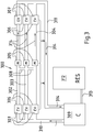
- FIG. 3 shows a superconducting cable system 300 with three superconducting cables 302, 303 and 304, which are each constructed from two cable sections A and B joined together at a sleeve 305.
- the superconducting cables 302, 303 and 304 are constructed, for example, as that in FIG Figure 2 cable 100 shown.
- Each of the superconducting cables 302, 303, 304 is provided with a termination 306 at its first end and at its last end.
- a pressure relief device 307 is arranged on each end closure 306, which releases coolant to the environment if necessary in order to prevent an inadmissible pressure increase in the inner container of the cable cryostat.
- Connections 308 are arranged between the sleeves 305, their structure and function in connection with FIG Figure 4 will be described in greater detail.
- a cooling system 309 is connected to the terminations 306 at the first end of the superconducting cables 302, 303, 304 via a supply line 310 for coolant.
- the terminations 306 at the second end of the superconducting cables 302, 303, 304 are connected to the cooling system 309 via a return line 311 for coolant.
- a coolant storage tank 312, which is advantageously designed as a cryotank, is connected to the cooling system 309 via a feed line 313.
- the supply line 310, the return line 311 and the feed line 313 are preferably designed as cryogenic lines, ie as double-walled vacuum-insulated lines.
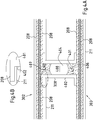
- Figure 4 Figure 12 shows one of the connections 308 in greater detail and in cross-section.
- connection 308 between cables 302 and 303 is shown.
- Figure 3 As can be seen, the connection 308 is arranged in the section core cable 302 or 303.
- the connection 308 can just as well be arranged in the section B of the cables 302 or 303.
- the connection 308 has an inner ear 401 and an outer tube 402.
- the inner ear 401 and the outer tube 402 are spaced apart from one another and enclose a space 403 which is evacuated and forms a vacuum-insulated cryostat.
- a special feature is that the cryostats of the connections 308 and the cables 302 and 303 overlap, so that a continuous vacuum insulation is achieved, while at the same time the vacuums in the cryostats of the cables 302, 303 and the connection 308 remain separated from each other, as especially from the in Figure 4B shown section can be seen. This has the advantage that if there is a loss of vacuum in a part of the cable system, the vacuum insulation of the entire cable system is not lost.
- the inner tube 401 of the connection 308 encloses an interior 404 in which a cavity 408 is delimited by means of two bursting disks 406, 407.
- the cavity 408 is approximately atmospheric pressure.
- the pressure in the cavity 408 is thus lower than in the interior of the cable cryostat, where the respective operating pressure of the coolant prevails.
- the coolant is, for example, liquid nitrogen (LN 2 ).
- the rupture disc 406 separates the coolant-filled interior of the cable 303 from the cavity 408, and the rupture disc 407 separates the coolant-filled interior of the cable 302 from the cavity 408. Consequently, there is no flow connection between the interiors of the cryostats of the cables 302, 303 during normal operation.
- the bursting disks 406, 407 are thin, concavo-convex steel disks, the convex side of which is directed towards the coolant, where the pressure is higher than in the cavity 408.
- connection 308 In a more simply structured modification of the invention, only a single rupture disk is provided in connection 308, which bursts when a correspondingly high pressure difference between the interior spaces of the cable cryostat that connects connection 308 to one another.
- the disadvantage of this modification is that the bursting of the rupture disk depends on a pressure difference, which in exceptional cases could lead to the pressure increase in the interior not being effectively limited. That would be the case, for example, if the pressure increases in both interior spaces at the same time. Fluctuations in the coolant pressure can also prevent the rupture disc from being triggered at a defined overpressure.
Landscapes
- Superconductors And Manufacturing Methods Therefor (AREA)
- Containers, Films, And Cooling For Superconductive Devices (AREA)
Description
- Die Erfindung betrifft ein supraleitfähiges Kabelsystem mit Überdruckschutz. Insbesondere betrifft die Erfindung ein supraleitfähiges Kabelsystem mit einer Berstscheibe.
- Supraleitfähiges Material hat unter anderem die Eigenschaft, dass sein elektrischer Widerstand auf Null sinkt, wenn es auf Temperaturen unterhalb der sogenannten Sprungtemperatur abgekühlt wird. Bei der Sprungtemperatur geht es in den sogenannten supraleitenden Zustand über. Der supraleitende Zustand existiert so lange wie die Temperatur T, die Stromstärke I und das magnetische Feld B unter entsprechenden kritischen Werten bleiben, die individuell von dem jeweiligen supraleitfähigen Material abhängen. Bevor im April 1986 Supraleitung in keramischen Materialien entdeckt wurde, war Supraleitung nur bei einigen Metallen bekannt. Unter den keramischen Supraleitern sind vor allem diejenigen Verbindungen von praktischer Bedeutung, deren Sprungtemperatur oberhalb der Temperatur von flüssigem Stickstoff (LN2) liegt, die 77 K (-196 °C) beträgt. Dieser Wert ist deshalb von besonderer Bedeutung, weil flüssiger Stickstoff ein vergleichsweise kostengünstiges Kühlmittel darstellt. Geeignete keramische Materialien sind beispielsweise mit seltenen Erden dotierte Materialien, die unter der Bezeichnung ReBCO (Rare-Earth-Barium-Kupfer-Oxid) bekannt geworden sind. Zu den keramischen Materialien, welche die genannten Eigenschaften erfüllen, gehört insbesondere YBCO (Yttrium-Barium-Kupfer-Oxid) mit einer Sprungtemperatur von 92 K. Ein anderes dieser supraleitfähigen Materialien ist beispielsweise BSCCO (Wismut-Strontium-Kalzium-Kupfer-Oxid) mit einer Sprungtemperatur von 110 K. Für die genannten supraleitfähigen Materialien geeignete Kühlmittel sind beispielsweise Stickstoff, Helium, Neon und Wasserstoff, jeweils in flüssigem Zustand.
- Ein supraleitfähiges Kabel hat in heutiger Technik elektrische Leiter aus einem Verbundwerkstoff, welcher keramisches Material enthält, das bei ausreichend tiefen Temperaturen in den supraleitenden Zustand übergeht. Der elektrische Gleichstromwiderstand eines entsprechend aufgebauten Leiters ist bei ausreichender Kühlung Null, solange eine bestimmte Stromstärke und eine bestimmte Magnetfeldstärke nicht überschritten werden. Um die erforderlichen niedrigeren Temperaturen zu erreichen, ist der supraleitfähige Leiter von einem Kabelkryostaten umgeben, der das Kühlmittel, insbesondere flüssigen Stickstoff, enthält und die Einstrahlung von Umgebungswärme auf das Kühlmittel und das supraleitfähige Kabel weitgehend unterbindet.
- Das supraleitfähige Kabel besteht aus einem druckfesten metallischen Innenbehälter oder Innenrohr, in dem das flüssige Kühlmittel vorhanden ist und in den das Kabel hineinragt und aus einem metallischen Außenbehälter oder Außenrohr, der vom Innenbehälter durch einen Zwischenraum getrennt ist, in dem eine Vakuumisolierung vorhanden ist. Der Innenbehälter muss so dimensioniert sein, dass er alle möglichen Druckerhöhungen, insbesondere schlagartige Druckerhöhungen, unbeschadet übersteht.
- Das Kühlmittel umspült und kühlt das Kabel. Das Kühlmittel dringt während der Inbetriebnahme des Systems nach und nach durch den Schirm des Kabels in dessen Dielektrikum ein. Im Betrieb des supraleitfähigen Kabels steht das Kältemittel unter einem bestimmten Betriebsdruck, um die dielektrische Festigkeit der Hochspannungsisolierung zu gewährleisten. Das Kühlmittel wirkt dabei auch als Imprägniermittel für das Dielektrikum.
- Größere Kabellängen werden realisiert, indem mehrere supraleitende Kabel mit Muffen zusammen gefügt werden, wie sie beispielsweise aus der europäischen Patentanmeldung
EP 2 105 994 A1 bekannt sind. Das Kabel ist in einem solchen Fall also aus mehreren Abschnitten oder Sektionen aufgebaut. Dementsprechend wird auch die Vakuumisolierung des Kabelkryostaten bei langen Systemen abschnittsweise realisiert, so dass typischerweise eine Vakuumsektion nicht länger als zwischen zwei Kabelmuffen ausgeführt wird. Bei einer mechanischen Beschädigung einer Vakuumsektion, bei der das Innenrohr intakt bleibt, verliert diese Sektion schlagartig die thermisch isolierende Wirkung des Vakuums. Infolgedessen entsteht durch die um mehrere Größenordnungen höhere Wärmelast ein Druckanstieg im System, der mittels Überdruckentlastungseinrichtungen im Rahmen gehalten muss. D.h. der Druck darf grundsätzlich nicht über eine Höchstbelastungsgrenze des Innenbehälters ansteigen. Die Druckentlastungseinrichtungen sind vorzugsweise an beiden Enden des Systems positioniert. Bei langen Systemen kann während der Druckentlastung jedoch ein erheblicher Druckabfall der Stickstoffströmung entlang des Innenbehälters von der Fehlerstelle zu einer Druckentlastungseinrichtung hin auftreten. Dieser Druckabfall kann zu einem Druck an der Fehlerstelle führen, der den zulässigen Druck des Innenbehälters für diesen Betriebsfall deutlich überschreitet, so dass eine Beschädigung des Innenbehälters auftreten kann. - Um dieser Gefahr zu begegnen, ist es bekannt, den hydraulischen Querschnitt des Innenbehälters und somit des gesamten supraleitfähigen Kabels zu vergrößern, so dass der Druckabfall entlang des Kabels entsprechend reduziert wird, wodurch im Fehlerfall der Druck im Innenbehälter den zulässigen Druck für den Innenbehälter nicht überschreitet. Alternativ dazu ist es bekannt, zusätzliche Druckentlastungseinrichtungen nach außen entlang der Kabelstrecke anzubringen. Bei der ersten Variante ist nachteilig, dass der Durchmesser des supraleitfähigen Kabels zunimmt, so dass der Installationsaufwand ebenfalls zunimmt. Darüber hinaus nimmt die maximale Kabellänge ab, die auf eine Kabelspule passt, so dass bei einer gegebenen Gesamtlänge eine größere Anzahl von Kabelabschnitten miteinander zu verbinden sind. Bei der zweiten Variante besteht die Gefahr, dass Verunreinigungen in das Innere des Kabelkryostaten eindringen können und bei einer nachfolgenden Wiederinbetriebnahme des Kabels Störungen verursachen können.
-
EP 2 418 747 A1 offenbart den Oberbegriff des Anspruchs 1. Hiervon ausgehend hat die vorliegende Erfindung die Aufgabe, ein supraleiterfähiges Kabelsystem mit wenigstens zwei supraleitfähigen Kabeln zu schaffen, deren Innenbehälter einen plötzlichen Druckanstieg unbeschadet übersteht, wobei gleichzeitig die Nachteile bekannter Lösungen vermieden werden sollen. - Zur Lösung dieser Aufgabe schlägt die Erfindung ein Kabelsystem mit wenigstens zwei supraleitfähigen Kabeln vor, die jeweils einen supraleitfähigen Leiter aufweisen, der in einem Innenraum eines vakuumisolierten Kabelkryostaten aufgenommen ist. In dem Kabelkryostaten ist Kühlmittel enthalten, das den supraleitfähigen Leiter im Betrieb des Kabelsystems auf Temperaturen unterhalb einer Sprungtemperatur des supraleitfähigen Leiters hält. Zwischen den kühlmittelführenden Innenräumen der Kabelkryostaten ist eine Verbindung angeordnet, die im Normalbetrieb mit einer Berstscheibe verschlossen ist, so dass die Innenräume der Kabelkryostaten strömungsmäßig voneinander getrennt sind.
- Wenn im Fehlerfall in dem Innenraum eines Kabelkryostaten ein unzulässig hoher Druck entsteht, der nicht ausreichend schnell über Druckentlastungseinrichtungen an den Enden des betreffenden supraleitfähigen Kabels abgeleitet werden kann, dann birst die Berstscheibe, worauf eine strömungsmäßige Verbindung zwischen den Innenräumen zweier supraleiterfähiger Kabel entsteht. Dadurch vergrößert sich der hydraulische Querschnitt des Kabelsystems durch den der Überdruck zu den Druckentlastungseinrichtungen hin abgeleitet werden kann. Auf diese Weise lässt sich der Druckanstieg in dem betroffenen Innenraum wirksam begrenzen, insbesondere auf Werte, die nicht zu einer Beschädigung eines Innenrohres des betroffenen Kabelkryostaten führen.
- Bei einer vorteilhaften Weiterbildung der Erfindung sind in der Verbindung zwei Berstscheiben angeordnet, zwischen denen ein Hohlraum eingeschlossen ist.
- Zweckmäßigerweise herrscht im Normalbetrieb des Kabelsystems in dem Hohlraum zwischen den zwei Berstscheiben ein Druck, der niedriger ist, als der Druck in den Innenräumen der Kabelkryostaten. Der Druck in dem Hohlraum ist ungefähr gleich wie der Atmosphärendruck. Durch diese Anordnung ist der Druck, bei dem die Berstscheibe auslöst sehr genau einstellbar.
- Bei einem vorteilhaften Ausführungsbeispiel haben die Berstscheiben eine konkav-konvexe Gestalt. In diesem Fall ist die konvexe Seite der Berstscheiben zu der Seite mit dem höheren Druck hin gerichtet.
- Mit Vorteil ist die Verbindung vakuumisoliert, um einen zusätzlichen Wärmeeintrag in das Kabelsystem durch die Verbindung möglichst gering zu halten.
- Vorteilhafterweise ist das Vakuum der Verbindung von dem Vakuum der Kabelkryostaten getrennt. Mehrere voneinander getrennte Sektionen der Vakuumisolierung stellen sicher, dass in einem Fehlerfall, bei dem ein Leck in einem Außenrohr entsteht, die Vakuumisolierung nur in einem Teilbereich des Kabelsystems verloren geht, während andere Bereiche intakt bleiben.
- Es hat sich als vorteilhaft erwiesen, wenn sich die vakuumisolierten Bereiche des Kabelkryostaten und der Verbindung überlappen. Auf diese Weise wird eine gute Isolierung sichergestellt.
- Nachfolgend wird die Erfindung anhand einer Ausführungsform unter Bezugnahme auf die begleitenden Figuren exemplarisch näher erläutert. Alle Figuren sind rein schematisch und nicht maßstäblich. Es zeigen:
- Fig. 1
- eine schematische Darstellung eines supraleitfähigen Kabels;
- Fig. 2
- eine schematische Darstellung des Aufbaus des supraleitfähigen Kabels aus
Figur 1 ; - Fig. 3
- ein Kabelsystem aus drei supraleitfähigen Kabeln im Normalbetrieb;
- Fig. 4A
- eine Doppelberstscheibeneinrichtung in einer Querschnittsansicht; und
- Fig. 4B
- ein Ausschnitt aus
Figur 4A . - Gleiche oder ähnliche Elemente sind in den Figuren mit gleichen oder ähnlichen Bezugszeichen versehen.
- In
Figur 1 ist rein schematisch ein supraleitfähiges Kabel 100 dargestellt, das an seinen Enden jeweils einen Endverschluss 101, 102 aufweist. Zwischen den Endverschlüssen 101, 102 erstreckt sich ein Kabelkryostat 103, der auch kurz als Kryostat bezeichnet wird. Der Kryostat 103 umschließt mindestens eine supraleitfähige Kabelader. Das supraleitfähige Kabel 100 bestehend aus Kryostat und Kabelader ist inFigur 2 in größerer Einzelheit dargestellt. Die Endverschlüsse 101, 102 ermöglichen den Anschluss des Supraleiterkabels an konventionelle Mittelspannungs- oder Hochspannungstechnik und dienen außerdem dazu, den Temperaturgradienten zwischen dem stickstoffgekühlten supraleitfähigen Kabel und damit in Berührung stehender Komponenten und der Umgebung zu bewältigen. - In einem anderen Ausführungsbeispiel ist anstelle des Endverschlusses 101 und oder des Endverschlusses 102 eine Muffe vorgesehen, die eine Verbindungsstelle zu einem weiteren supraleitfähigen Kabel 100 bildet. Auf diese Weise ist es möglich, das supraleitfähige Kabel 100 zu verlängern.
-
Figur 2 zeigt beispielhaft den Aufbau des supraleitfähigen Kabels 100. Auf einem hohlen Formkörper 200, der einen Hohlraum 201 umschließt, sind supraleitfähige Bänder angeordnet, die eine supraleitfähige Schicht 202 bilden. Die supraleitfähige Schicht 202 ist von einer bandförmigen halbleitenden Leiterglättung 203 umgeben. Auf der Leiterglättung 203 ist ein Dielektrikum 204 angeordnet, dass von einem elektrisch leitenden Schirm 206 umgeben ist, der zum Beispiel aus Kupferdrähten oder Kupferbändern oder ebenfalls aus supraleitfähigen Bändern gebildet ist. Zwischen Dielektrikum 204 und Schirm 206 ist eine weitere halbleitende Schicht (nicht dargestellt) angeordnet. Die halbleitenden Schichten dienen der Glättung des elektrischen Felds im Kabel, indem sie runde Oberflächen schaffen und Kanten eliminieren. - Die genannten Komponenten sind in einem Hohlraum 207 angeordnet, der von einem inneren Kryostatrohr oder Innenrohr 208 umschlossen ist. Im Betrieb des supraleitfähigen Kabels 100 fließt das zur Kühlung eingesetzte Kühlmittel in dem Hohlraum 207. Die Außenseite des inneren Kryostatrohres 208 ist von einer Superisolation 209 umgeben, die ihrerseits von einem äußeren Kryostatrohr oder Außenrohr 211 eingeschlossen ist. Der Zwischenraum zwischen dem inneren Kryostatrohr 208 und dem äußeren Kryostatrohr 211 ist evakuiert und bildet eine Vakuumisolation zwischen dem inneren Kryostatrohr 208 und dem äußeren Kryostatrohr 211. Bei manchen Ausführungsbeispielen sind zusätzlich zu der Superisolation 209 Abstandshalter (nicht gezeigt) vorgesehen, die verhindern, dass sich die Kryostatrohre 208, 211 berühren. Die Kryostatrohre 208, 211 sind vorzugsweise aus Edelstahl hergestellt. Mit Vorteil sind die Kryostatrohre 208, quer zu ihrer Längsrichtung oder schraubenlinienförmig gewellt. Zum Schutz vor Beschädigungen und vor anderen Umwelteinflüssen wie Feuchtigkeit oder aggressiven Substanzen ist das äußere Kryostatrohr 211 von einem Mantel umgeben, der beispielsweise aus Polyethylen (PE) oder (PVC) hergestellt ist.
-
Figur 3 zeigt ein supraleitfähiges Kabelsystem 300 mit drei supraleitfähigen Kabeln 302, 303 und 304, die jeweils aus zwei an einer Muffe 305 zusammengefügten Kabelabschnitten A und B aufgebaut sind. Die supraleitfähigen Kabeln 302, 303 und 304 sind beispielsweise so aufgebaut wie das inFigur 2 gezeigte Kabel 100. Jedes der supraleitfähigen Kabel 302, 303, 304 ist an seinem ersten Ende und an seinem letzten Ende mit einem Endverschluss 306 versehen. An jedem Endverschluss 306 ist jeweils eine Druckentlastungseinrichtung 307 angeordnet, die im Bedarfsfall Kühlmittel an die Umgebung abgibt, um einen unzulässigen Druckanstieg in dem Innenbehälter der Kabelkryostaten zu verhindern. Zwischen den Muffen 305 sind Verbindungen 308 angeordnet, deren Aufbau und Funktion weiter unten im Zusammenhang mitFigur 4 in größerer Einzelheit beschrieben wird. - Eine Kühlanlage 309 ist über eine Zufuhrleitung 310 für Kühlmittel mit den Endverschlüssen 306 an dem ersten Ende der supraleitfähigen Kabel 302, 303, 304 verbunden. Die Endverschlüsse 306 an dem zweiten Ende der supraleitfähigen Kabel 302, 303, 304 sind über eine Rückleitung 311 für Kühlmittel an die Kühlanlage 309 angeschlossen. Ein Kühlmittelvorratstank 312, der mit Vorteil als Kryotank ausgebildet ist, ist über eine Speiseleitung 313 mit der Kühlanlage 309 verbunden. Die Zufuhrleitung 310, die Rückleitung 311 sowie die Speiseleitung 313 sind vorzugsweise als Kryoleitungen ausgebildet, d.h. als doppelwandige vakuumisolierte Leitungen.
-
Figur 4 zeigt eine der Verbindungen 308 in größerer Einzelheit und im Querschnitt. InFigur 4A ist zum Beispiel die Verbindung 308 zwischen dem Kabel 302 und 303 gezeigt. Wie ausFigur 3 ersichtlich ist, ist die Verbindung 308 in dem Abschnitt Ader Kabel 302 bzw. 303 angeordnet. Die Verbindung 308 kann aber ebenso gut in dem Abschnitt B der Kabel 302 bzw. 303 angeordnet sein. - Die Verbindung 308 weist ein Innenohr 401 sowie ein Außenrohr 402 auf. Das Innenohr 401 und das Außenrohr 402 sind voneinander beabstandet und schließen einen Zwischenraum 403 ein, der evakuiert ist und einen vakuumisolierten Kryostaten bildet. Eine Besonderheit besteht darin, dass sich die Kryostaten der Verbindungen 308 und der Kabel 302 bzw. 303 überlappen, so dass eine durchgängige Vakuumisolierung erreicht wird, wobei gleichzeitig die Vakua in den Kryostaten der Kabel 302, 303 und der Verbindung 308 voneinander getrennt bleiben, wie es insbesondere aus dem in
Figur 4B gezeigten Ausschnitt ersichtlich ist. Das hat den Vorteil, dass bei einem Vakuumverlust in einem Teilbereich des Kabelsystems nicht die Vakuumisolierung des gesamten Kabelsystems verloren geht. Das Innenrohr 401 der Verbindung 308 umschließt einen Innenraum 404, in welchem mittels zweier Berstscheiben 406,407 ein Hohlraum 408 abgegrenzt ist. In dem Hohlraum 408 herrscht ungefähr Atmosphärendruck. Der Druck in dem Hohlraum 408 ist somit geringer als in den Innenräumen der Kabelkryostaten, wo der jeweilige Betriebsdruck des Kühlmittels herrscht. Das Kühlmittel ist zum Beispiel flüssiger Stickstoff (LN2). - Die Berstscheibe 406 trennt den mit Kühlmittel gefüllten Innenraum des Kabels 303 von dem Hohlraum 408 und die Berstscheibe 407 trennt den mit Kühlmittel gefühlt Innenraum des Kabels 302 von dem Hohlraum 408 ab. Folglich besteht im Normalbetrieb zwischen den Innenräumen der Kryostaten der Kabel 302,303 keine strömungsmäßige Verbindung. Die Berstscheiben 406,407 sind dünne, konkav-konvex ausgebildete Stahlscheiben, deren konvexe Seite jeweils zu dem Kühlmittel hin gerichtet ist, wo der Druck höher ist als in dem Hohlraum 408.
- Im Falle einer mechanischen Beschädigung eines Außenrohres eines Kabelkryostaten verliert der betreffende Abschnitt des supraleitfähigen Kabels schlagartig seine thermische Isolierung. In der Folge entsteht eine um mehrere Größenordnungen höhere Wärmelast, die dazu führt, dass Kühlmittel - zum Beispiel flüssiger Stickstoff - verdampft und ein erheblicher Druckanstieg in dem Innenrohr des Kabelkryostaten erfolgt. In dem beschriebenen Fehlerfall ist der Druckanstieg in der Regel so hoch, dass er ohne Druckentlastung zu einer Beschädigung des Innenrohres führt. Wie eingangs beschrieben wurde, sind Druckentlastungseinrichtungen 307 an den Endverschlüssen 306 des betroffenen supraleitfähigen Kabels in vielen Fällen nicht ausreichend, um den Druckanstieg auf Werte zu begrenzen, denen das Innenohr unbeschadet widerstehen kann. Die Berstscheiben 406,407 dienen dazu, den Druckanstieg wirksam zu begrenzen.
- Unter der Annahme, dass das Außenrohr des Kabels 302 in einem Abschnitt beschädigt wird, steigt der Innendruck in dem entsprechenden Innenraum desselben Abschnittes schlagartig an und bringt die Berstscheibe 407 zum Bersten, so dass das unter hohem Druck stehende Kühlmittel aus dem Innenraum des Kabels 302 den Hohlraum 408 füllt und dadurch die Berstscheibe 406 ebenfalls zum Bersten bringt. In diesem Moment entsteht eine strömungsmäßige Verbindung zwischen den Innenräumen der Kabelkryostaten der Kabel 302 und 303 mit der Folge, dass sich der hydraulische Querschnitt, der zur Ableitung des Überdruckes zur Verfügung steht, verdoppelt. Auf diese Weise gelingt es, den Druckanstieg in dem von der Beschädigung betroffenen Kabelabschnitt auf Werte zu begrenzen, bei denen keine Beschädigung des Innenrohres eintritt.
- Bei Beschädigung von mehreren Kabelabschnitten, bei der es zu einem extremen Druckanstieg kommt, ist es auch möglich, dass die Berstscheiben in mehreren Verbindungen bersten und die Innenräume von mehr als zwei Kabeln strömungsmäßig miteinander verbunden werden und damit gemeinsam zur Verfügung stehen, um den Überdruck abzuleiten.
- Bei einer einfacher aufgebauten Abwandlung der Erfindung ist in der Verbindung 308 nur eine einzige Berstscheibe vorgesehen, die dann birst, wenn eine entsprechend hohe Druckdifferenz zwischen den Innenräumen der Kabelkryostaten herrscht, welche die Verbindung 308 miteinander verbindet. Nachteilig ist bei dieser Abwandlung, dass das Bersten der Berstscheibe von einer Druckdifferenz abhängt, was in Ausnahmefällen dazu führen könnte, dass der Druckanstieg in den Innenräumen nicht wirksam begrenzt wird. Das wäre beispielsweise dann der Fall, wenn der Druck in beiden Innenräumen gleichzeitig ansteigt. Schwankungen des Kühlmitteldruckes können auch dazu führen, dass die Berstscheibe nicht bei einem definierten Überdruck auslöst.
- Diese Nachteile werden durch die Anordnung mit zwei Berstscheiben vermieden.
Bezuaszeichenliste 100 supraleitfähiges Kabel 401 Innenohr 101,102 Endverschluss 402 Außenrohr 200 Formkörper 403 Zwischenraum 201 Hohlraum 404 Innenraum 202 Supraleitfähige Leiterschicht 406,407 Berstscheiben. 203 Leiterglättung 408 Hohlraum 204 Dielektrikum 206 Schirm 207 Hohlraum 208 Inneres Kryostatrohr 209 Superisolation 211 Äußeres Kryostatrohr 212 Mantel 300 Kabelsystem 302-304 Kabel 306 Endverschluss 307 Druckentlastungseinrichtung 308 Verbindungsleitung 309 Kühlanlage 310 Zufuhrleitung 311 Rückleitung 312 Vorratstank 313 Speiseleitung 314 Strömungsrichtung
Claims (7)
- Kabelsystem (300) mit wenigstens zwei supraleitfähigen Kabeln (302-304), die jeweils einen supraleitfähigen Leiter aufweisen, der in einem Innenraum eines vakuumisolierten Kabelkryostaten aufgenommen ist, in welchem Kühlmittel enthalten ist, das den supraleitfähigen Leiter im Betrieb des Kabelsystems auf Temperaturen unterhalb einer Sprungtemperatur des supraleitfähigen Leiters hält, wobei zwischen dem kühlmittelführenden Innenräumen der Kabelkryostaten eine Verbindung (308) angeordnet ist, dadurch gekennzeichnet, dass die Verbindung im Normalbetrieb mit einer Berstscheibe (406,407) verschlossen ist, so dass die Innenräume der Kabelkryostaten strömungsmäßig voneinander getrennt sind.
- Kabelsystem nach Anspruch 1, dadurch gekennzeichnet, dass in der Verbindung (308) zwei Berstscheiben (406,407) angeordnet sind, zwischen denen ein Hohlraum (408) eingeschlossen ist.
- Kabelsystem nach Anspruch 2, dadurch gekennzeichnet, dass im Normalbetrieb des Kabelsystems in dem Hohlraum (408) zwischen den zwei Berstscheiben (406,407) ein Druck herrscht, der niedriger ist, als der Druck in den Innenräumen der Kabelkryostaten.
- Kabelsystem nach Anspruch 2 oder 3, dadurch gekennzeichnet, dass die Berstscheiben (406,407) eine konkav-konvexe Gestalt haben.
- Kabelsystem nach einem der vorstehenden Ansprüche, dadurch gekennzeichnet, dass die Verbindung (308) vakuumisoliert ist.
- Kabelsystem nach einem der vorstehenden Ansprüche, dadurch gekennzeichnet, dass das Vakuum der Verbindung von dem Vakuum der Kabelkryostaten getrennt ist.
- Kabelsystem nach einem der vorstehenden Ansprüche, dadurch gekennzeichnet, dass sich die vakuumisolierten Bereiche des Kabelkryostaten und der Verbindung überlappen.
Priority Applications (2)
| Application Number | Priority Date | Filing Date | Title |
|---|---|---|---|
| EP18305138.2A EP3525306B1 (de) | 2018-02-09 | 2018-02-09 | Supraleitfähiges kabelsystem mit überdruckschutz |
| DK18305138.2T DK3525306T3 (da) | 2018-02-09 | 2018-02-09 | Superledende kabelsystem med overtryksbeskyttelse |
Applications Claiming Priority (1)
| Application Number | Priority Date | Filing Date | Title |
|---|---|---|---|
| EP18305138.2A EP3525306B1 (de) | 2018-02-09 | 2018-02-09 | Supraleitfähiges kabelsystem mit überdruckschutz |
Publications (2)
| Publication Number | Publication Date |
|---|---|
| EP3525306A1 EP3525306A1 (de) | 2019-08-14 |
| EP3525306B1 true EP3525306B1 (de) | 2020-09-09 |
Family
ID=61249589
Family Applications (1)
| Application Number | Title | Priority Date | Filing Date |
|---|---|---|---|
| EP18305138.2A Active EP3525306B1 (de) | 2018-02-09 | 2018-02-09 | Supraleitfähiges kabelsystem mit überdruckschutz |
Country Status (2)
| Country | Link |
|---|---|
| EP (1) | EP3525306B1 (de) |
| DK (1) | DK3525306T3 (de) |
Family Cites Families (4)
| Publication number | Priority date | Publication date | Assignee | Title |
|---|---|---|---|---|
| JP4399770B2 (ja) * | 2003-09-19 | 2010-01-20 | 住友電気工業株式会社 | 超電導ケーブルの運転方法および超電導ケーブルシステム |
| DK1887671T3 (da) * | 2006-08-07 | 2013-10-28 | Nexans | Endeafslutning for et superledende kabel |
| FR2929454B1 (fr) | 2008-03-26 | 2012-05-04 | Nexans | Dispositif de connexion de deux cables supraconducteurs |
| DK2418747T3 (en) * | 2010-08-13 | 2016-02-08 | Nexans | Device for the electrically conductive connection of two electrical devices |
-
2018
- 2018-02-09 DK DK18305138.2T patent/DK3525306T3/da active
- 2018-02-09 EP EP18305138.2A patent/EP3525306B1/de active Active
Non-Patent Citations (1)
| Title |
|---|
| None * |
Also Published As
| Publication number | Publication date |
|---|---|
| DK3525306T3 (da) | 2020-11-30 |
| EP3525306A1 (de) | 2019-08-14 |
Similar Documents
| Publication | Publication Date | Title |
|---|---|---|
| EP2698794B1 (de) | Anordnung mit mindestens einem supraleitfähigen Kabel | |
| EP2685469B1 (de) | Anordnung mit mindestens einem supraleitfähigen Kabel | |
| DE60129172T2 (de) | Stromtransportsystem mit einem kalten dielektrischen supraleitenden kabel | |
| EP2228806B1 (de) | Anordnung zur Strombegrenzung | |
| DE112016003022T5 (de) | Supraleitender Draht | |
| EP3258562B1 (de) | Verfahren zum aufbau einer übertragungsstrecke für elektrische energie | |
| EP2418747B1 (de) | Anordnung zum elektrisch leitenden Verbinden von zwei elektrischen Einheiten | |
| EP1738376B1 (de) | Supraleitendes kabel und verfahren zur herstellung desselben | |
| EP2328156B1 (de) | Verfahren zum Betrieb einer Anordnung mit mindestens einem supraleitfähigen Kabel | |
| EP2071589B1 (de) | Supraleitfähiges elektrisches Kabel | |
| DE1937795A1 (de) | Abstandhalter aus schlecht waermeleitendem Material zwischen je zwei einander umschliessenden Rohren,insbesondere bei tiefgekuehlten Kabeln | |
| EP2426676A1 (de) | Anordnung mit mindestens einem supraleitfähigen Kabel | |
| EP2317526B1 (de) | System mit mindestens einem supraleitfähigen Kabel | |
| EP2234122B1 (de) | Supraleitfähiges elektrisches Kabel | |
| EP2339593B1 (de) | Supraleitfähiges Kabelsystem | |
| EP2002454A1 (de) | Kryostat mit einem magnetspulensystem, das eine lts- und eine gekapselte hts-sektion umfasst | |
| EP1887584A1 (de) | System mit einem supraleitfähigen Kabel | |
| DE3811051C2 (de) | ||
| EP2634779B1 (de) | System mit einem dreiphasigen supraleitfähigen elektrischen Übertragungselement | |
| DE102014224363A1 (de) | Vorrichtung der Supraleitungstechnik mitSpuleneinrichtungen und Kühlvorrichtung sowie damitausgestattetes Fahrzeug | |
| EP1865516B1 (de) | System mit einem supraleitfähigen Kabel | |
| DE202019003381U1 (de) | Muffe für ein supraleitfähiges Kabel und supraleitfähiges Kabel mit Anschluss für eine Zwischenkühlung | |
| DE2249560B2 (de) | Endverschluß für ein tiefgekühltes Kabel | |
| EP3525306A1 (de) | Supraleitfähiges kabelsystem mit überdruckschutz | |
| EP1887671B1 (de) | Endenabschluss für ein supraleitfähiges Kabel |
Legal Events
| Date | Code | Title | Description |
|---|---|---|---|
| PUAI | Public reference made under article 153(3) epc to a published international application that has entered the european phase |
Free format text: ORIGINAL CODE: 0009012 |
|
| STAA | Information on the status of an ep patent application or granted ep patent |
Free format text: STATUS: THE APPLICATION HAS BEEN PUBLISHED |
|
| AK | Designated contracting states |
Kind code of ref document: A1 Designated state(s): AL AT BE BG CH CY CZ DE DK EE ES FI FR GB GR HR HU IE IS IT LI LT LU LV MC MK MT NL NO PL PT RO RS SE SI SK SM TR |
|
| AX | Request for extension of the european patent |
Extension state: BA ME |
|
| STAA | Information on the status of an ep patent application or granted ep patent |
Free format text: STATUS: REQUEST FOR EXAMINATION WAS MADE |
|
| 17P | Request for examination filed |
Effective date: 20200214 |
|
| RBV | Designated contracting states (corrected) |
Designated state(s): AL AT BE BG CH CY CZ DE DK EE ES FI FR GB GR HR HU IE IS IT LI LT LU LV MC MK MT NL NO PL PT RO RS SE SI SK SM TR |
|
| GRAP | Despatch of communication of intention to grant a patent |
Free format text: ORIGINAL CODE: EPIDOSNIGR1 |
|
| STAA | Information on the status of an ep patent application or granted ep patent |
Free format text: STATUS: GRANT OF PATENT IS INTENDED |
|
| INTG | Intention to grant announced |
Effective date: 20200406 |
|
| RIN1 | Information on inventor provided before grant (corrected) |
Inventor name: ESSLER, JUERGEN Inventor name: SCHMIDT, FRANK Inventor name: ALLWEINS, KAI |
|
| GRAS | Grant fee paid |
Free format text: ORIGINAL CODE: EPIDOSNIGR3 |
|
| GRAA | (expected) grant |
Free format text: ORIGINAL CODE: 0009210 |
|
| STAA | Information on the status of an ep patent application or granted ep patent |
Free format text: STATUS: THE PATENT HAS BEEN GRANTED |
|
| AK | Designated contracting states |
Kind code of ref document: B1 Designated state(s): AL AT BE BG CH CY CZ DE DK EE ES FI FR GB GR HR HU IE IS IT LI LT LU LV MC MK MT NL NO PL PT RO RS SE SI SK SM TR |
|
| REG | Reference to a national code |
Ref country code: GB Ref legal event code: FG4D Free format text: NOT ENGLISH |
|
| REG | Reference to a national code |
Ref country code: AT Ref legal event code: REF Ref document number: 1312754 Country of ref document: AT Kind code of ref document: T Effective date: 20200915 Ref country code: CH Ref legal event code: EP |
|
| REG | Reference to a national code |
Ref country code: DE Ref legal event code: R096 Ref document number: 502018002405 Country of ref document: DE |
|
| REG | Reference to a national code |
Ref country code: IE Ref legal event code: FG4D Free format text: LANGUAGE OF EP DOCUMENT: GERMAN |
|
| REG | Reference to a national code |
Ref country code: DK Ref legal event code: T3 Effective date: 20201126 |
|
| REG | Reference to a national code |
Ref country code: LT Ref legal event code: MG4D |
|
| PG25 | Lapsed in a contracting state [announced via postgrant information from national office to epo] |
Ref country code: FI Free format text: LAPSE BECAUSE OF FAILURE TO SUBMIT A TRANSLATION OF THE DESCRIPTION OR TO PAY THE FEE WITHIN THE PRESCRIBED TIME-LIMIT Effective date: 20200909 Ref country code: HR Free format text: LAPSE BECAUSE OF FAILURE TO SUBMIT A TRANSLATION OF THE DESCRIPTION OR TO PAY THE FEE WITHIN THE PRESCRIBED TIME-LIMIT Effective date: 20200909 Ref country code: BG Free format text: LAPSE BECAUSE OF FAILURE TO SUBMIT A TRANSLATION OF THE DESCRIPTION OR TO PAY THE FEE WITHIN THE PRESCRIBED TIME-LIMIT Effective date: 20201209 Ref country code: NO Free format text: LAPSE BECAUSE OF FAILURE TO SUBMIT A TRANSLATION OF THE DESCRIPTION OR TO PAY THE FEE WITHIN THE PRESCRIBED TIME-LIMIT Effective date: 20201209 Ref country code: SE Free format text: LAPSE BECAUSE OF FAILURE TO SUBMIT A TRANSLATION OF THE DESCRIPTION OR TO PAY THE FEE WITHIN THE PRESCRIBED TIME-LIMIT Effective date: 20200909 Ref country code: LT Free format text: LAPSE BECAUSE OF FAILURE TO SUBMIT A TRANSLATION OF THE DESCRIPTION OR TO PAY THE FEE WITHIN THE PRESCRIBED TIME-LIMIT Effective date: 20200909 Ref country code: GR Free format text: LAPSE BECAUSE OF FAILURE TO SUBMIT A TRANSLATION OF THE DESCRIPTION OR TO PAY THE FEE WITHIN THE PRESCRIBED TIME-LIMIT Effective date: 20201210 |
|
| REG | Reference to a national code |
Ref country code: NL Ref legal event code: MP Effective date: 20200909 |
|
| PG25 | Lapsed in a contracting state [announced via postgrant information from national office to epo] |
Ref country code: PL Free format text: LAPSE BECAUSE OF FAILURE TO SUBMIT A TRANSLATION OF THE DESCRIPTION OR TO PAY THE FEE WITHIN THE PRESCRIBED TIME-LIMIT Effective date: 20200909 Ref country code: LV Free format text: LAPSE BECAUSE OF FAILURE TO SUBMIT A TRANSLATION OF THE DESCRIPTION OR TO PAY THE FEE WITHIN THE PRESCRIBED TIME-LIMIT Effective date: 20200909 Ref country code: RS Free format text: LAPSE BECAUSE OF FAILURE TO SUBMIT A TRANSLATION OF THE DESCRIPTION OR TO PAY THE FEE WITHIN THE PRESCRIBED TIME-LIMIT Effective date: 20200909 |
|
| PG25 | Lapsed in a contracting state [announced via postgrant information from national office to epo] |
Ref country code: CZ Free format text: LAPSE BECAUSE OF FAILURE TO SUBMIT A TRANSLATION OF THE DESCRIPTION OR TO PAY THE FEE WITHIN THE PRESCRIBED TIME-LIMIT Effective date: 20200909 Ref country code: RO Free format text: LAPSE BECAUSE OF FAILURE TO SUBMIT A TRANSLATION OF THE DESCRIPTION OR TO PAY THE FEE WITHIN THE PRESCRIBED TIME-LIMIT Effective date: 20200909 Ref country code: PT Free format text: LAPSE BECAUSE OF FAILURE TO SUBMIT A TRANSLATION OF THE DESCRIPTION OR TO PAY THE FEE WITHIN THE PRESCRIBED TIME-LIMIT Effective date: 20210111 Ref country code: EE Free format text: LAPSE BECAUSE OF FAILURE TO SUBMIT A TRANSLATION OF THE DESCRIPTION OR TO PAY THE FEE WITHIN THE PRESCRIBED TIME-LIMIT Effective date: 20200909 Ref country code: SM Free format text: LAPSE BECAUSE OF FAILURE TO SUBMIT A TRANSLATION OF THE DESCRIPTION OR TO PAY THE FEE WITHIN THE PRESCRIBED TIME-LIMIT Effective date: 20200909 |
|
| PG25 | Lapsed in a contracting state [announced via postgrant information from national office to epo] |
Ref country code: IS Free format text: LAPSE BECAUSE OF FAILURE TO SUBMIT A TRANSLATION OF THE DESCRIPTION OR TO PAY THE FEE WITHIN THE PRESCRIBED TIME-LIMIT Effective date: 20210109 Ref country code: ES Free format text: LAPSE BECAUSE OF FAILURE TO SUBMIT A TRANSLATION OF THE DESCRIPTION OR TO PAY THE FEE WITHIN THE PRESCRIBED TIME-LIMIT Effective date: 20200909 Ref country code: AL Free format text: LAPSE BECAUSE OF FAILURE TO SUBMIT A TRANSLATION OF THE DESCRIPTION OR TO PAY THE FEE WITHIN THE PRESCRIBED TIME-LIMIT Effective date: 20200909 |
|
| REG | Reference to a national code |
Ref country code: DE Ref legal event code: R097 Ref document number: 502018002405 Country of ref document: DE |
|
| PG25 | Lapsed in a contracting state [announced via postgrant information from national office to epo] |
Ref country code: SK Free format text: LAPSE BECAUSE OF FAILURE TO SUBMIT A TRANSLATION OF THE DESCRIPTION OR TO PAY THE FEE WITHIN THE PRESCRIBED TIME-LIMIT Effective date: 20200909 |
|
| PLBE | No opposition filed within time limit |
Free format text: ORIGINAL CODE: 0009261 |
|
| STAA | Information on the status of an ep patent application or granted ep patent |
Free format text: STATUS: NO OPPOSITION FILED WITHIN TIME LIMIT |
|
| 26N | No opposition filed |
Effective date: 20210610 |
|
| PG25 | Lapsed in a contracting state [announced via postgrant information from national office to epo] |
Ref country code: SI Free format text: LAPSE BECAUSE OF FAILURE TO SUBMIT A TRANSLATION OF THE DESCRIPTION OR TO PAY THE FEE WITHIN THE PRESCRIBED TIME-LIMIT Effective date: 20200909 |
|
| PG25 | Lapsed in a contracting state [announced via postgrant information from national office to epo] |
Ref country code: MC Free format text: LAPSE BECAUSE OF FAILURE TO SUBMIT A TRANSLATION OF THE DESCRIPTION OR TO PAY THE FEE WITHIN THE PRESCRIBED TIME-LIMIT Effective date: 20200909 |
|
| REG | Reference to a national code |
Ref country code: BE Ref legal event code: MM Effective date: 20210228 |
|
| PG25 | Lapsed in a contracting state [announced via postgrant information from national office to epo] |
Ref country code: CH Free format text: LAPSE BECAUSE OF NON-PAYMENT OF DUE FEES Effective date: 20210228 Ref country code: LI Free format text: LAPSE BECAUSE OF NON-PAYMENT OF DUE FEES Effective date: 20210228 Ref country code: LU Free format text: LAPSE BECAUSE OF NON-PAYMENT OF DUE FEES Effective date: 20210209 |
|
| PG25 | Lapsed in a contracting state [announced via postgrant information from national office to epo] |
Ref country code: FR Free format text: LAPSE BECAUSE OF NON-PAYMENT OF DUE FEES Effective date: 20210228 Ref country code: IE Free format text: LAPSE BECAUSE OF NON-PAYMENT OF DUE FEES Effective date: 20210209 |
|
| PG25 | Lapsed in a contracting state [announced via postgrant information from national office to epo] |
Ref country code: BE Free format text: LAPSE BECAUSE OF NON-PAYMENT OF DUE FEES Effective date: 20210228 |
|
| GBPC | Gb: european patent ceased through non-payment of renewal fee |
Effective date: 20220209 |
|
| PG25 | Lapsed in a contracting state [announced via postgrant information from national office to epo] |
Ref country code: GB Free format text: LAPSE BECAUSE OF NON-PAYMENT OF DUE FEES Effective date: 20220209 |
|
| PG25 | Lapsed in a contracting state [announced via postgrant information from national office to epo] |
Ref country code: NL Free format text: LAPSE BECAUSE OF NON-PAYMENT OF DUE FEES Effective date: 20200923 Ref country code: CY Free format text: LAPSE BECAUSE OF FAILURE TO SUBMIT A TRANSLATION OF THE DESCRIPTION OR TO PAY THE FEE WITHIN THE PRESCRIBED TIME-LIMIT Effective date: 20200909 |
|
| PG25 | Lapsed in a contracting state [announced via postgrant information from national office to epo] |
Ref country code: HU Free format text: LAPSE BECAUSE OF FAILURE TO SUBMIT A TRANSLATION OF THE DESCRIPTION OR TO PAY THE FEE WITHIN THE PRESCRIBED TIME-LIMIT; INVALID AB INITIO Effective date: 20180209 |
|
| REG | Reference to a national code |
Ref country code: AT Ref legal event code: MM01 Ref document number: 1312754 Country of ref document: AT Kind code of ref document: T Effective date: 20230209 |
|
| PG25 | Lapsed in a contracting state [announced via postgrant information from national office to epo] |
Ref country code: AT Free format text: LAPSE BECAUSE OF NON-PAYMENT OF DUE FEES Effective date: 20230209 |
|
| PG25 | Lapsed in a contracting state [announced via postgrant information from national office to epo] |
Ref country code: MK Free format text: LAPSE BECAUSE OF FAILURE TO SUBMIT A TRANSLATION OF THE DESCRIPTION OR TO PAY THE FEE WITHIN THE PRESCRIBED TIME-LIMIT Effective date: 20200909 Ref country code: AT Free format text: LAPSE BECAUSE OF NON-PAYMENT OF DUE FEES Effective date: 20230209 |
|
| PG25 | Lapsed in a contracting state [announced via postgrant information from national office to epo] |
Ref country code: MT Free format text: LAPSE BECAUSE OF FAILURE TO SUBMIT A TRANSLATION OF THE DESCRIPTION OR TO PAY THE FEE WITHIN THE PRESCRIBED TIME-LIMIT Effective date: 20200909 |
|
| PG25 | Lapsed in a contracting state [announced via postgrant information from national office to epo] |
Ref country code: TR Free format text: LAPSE BECAUSE OF FAILURE TO SUBMIT A TRANSLATION OF THE DESCRIPTION OR TO PAY THE FEE WITHIN THE PRESCRIBED TIME-LIMIT Effective date: 20200909 |
|
| PGFP | Annual fee paid to national office [announced via postgrant information from national office to epo] |
Ref country code: DE Payment date: 20260218 Year of fee payment: 9 Ref country code: DK Payment date: 20260220 Year of fee payment: 9 |
|
| PGFP | Annual fee paid to national office [announced via postgrant information from national office to epo] |
Ref country code: AT Payment date: 20260410 Year of fee payment: 5 |
|
| PGFP | Annual fee paid to national office [announced via postgrant information from national office to epo] |
Ref country code: IT Payment date: 20260224 Year of fee payment: 9 |