EP3525299A1 - Crimping tool, base, ram assembly, plant and method of changing between tools of a crimping tool - Google Patents
Crimping tool, base, ram assembly, plant and method of changing between tools of a crimping tool Download PDFInfo
- Publication number
- EP3525299A1 EP3525299A1 EP18156061.6A EP18156061A EP3525299A1 EP 3525299 A1 EP3525299 A1 EP 3525299A1 EP 18156061 A EP18156061 A EP 18156061A EP 3525299 A1 EP3525299 A1 EP 3525299A1
- Authority
- EP
- European Patent Office
- Prior art keywords
- crimping
- tool
- ram assembly
- tools
- accordance
- Prior art date
- Legal status (The legal status is an assumption and is not a legal conclusion. Google has not performed a legal analysis and makes no representation as to the accuracy of the status listed.)
- Granted
Links
Images

Classifications
-
- H—ELECTRICITY
- H01—ELECTRIC ELEMENTS
- H01R—ELECTRICALLY-CONDUCTIVE CONNECTIONS; STRUCTURAL ASSOCIATIONS OF A PLURALITY OF MUTUALLY-INSULATED ELECTRICAL CONNECTING ELEMENTS; COUPLING DEVICES; CURRENT COLLECTORS
- H01R43/00—Apparatus or processes specially adapted for manufacturing, assembling, maintaining, or repairing of line connectors or current collectors or for joining electric conductors
- H01R43/04—Apparatus or processes specially adapted for manufacturing, assembling, maintaining, or repairing of line connectors or current collectors or for joining electric conductors for forming connections by deformation, e.g. crimping tool
- H01R43/048—Crimping apparatus or processes
-
- H—ELECTRICITY
- H01—ELECTRIC ELEMENTS
- H01R—ELECTRICALLY-CONDUCTIVE CONNECTIONS; STRUCTURAL ASSOCIATIONS OF A PLURALITY OF MUTUALLY-INSULATED ELECTRICAL CONNECTING ELEMENTS; COUPLING DEVICES; CURRENT COLLECTORS
- H01R43/00—Apparatus or processes specially adapted for manufacturing, assembling, maintaining, or repairing of line connectors or current collectors or for joining electric conductors
- H01R43/04—Apparatus or processes specially adapted for manufacturing, assembling, maintaining, or repairing of line connectors or current collectors or for joining electric conductors for forming connections by deformation, e.g. crimping tool
- H01R43/048—Crimping apparatus or processes
- H01R43/0488—Crimping apparatus or processes with crimp height adjusting means
Definitions
- the present invention relates to a crimping tool for connecting terminals to components, the crimping tool comprising a ram assembly; and a plurality of tools, with each tool being configured to cooperate with a crimping anvil to connect the terminals to respective components.
- the invention further relates to a respective base for a crimping tool, to a ram assembly for a crimping tool, to a plant for the automated production of wiring harnesses and to a method of changing between tools of a crimping tool.
- Crimping is the process of joining two or more components, such as pieces of metal or other ductile material to one another.
- the joint is formed by deforming one or more of the pieces to be joined.
- electrical terminals are joined to conductors of electric cables in order to use the terminal to connect the cable to an electronic installation.
- the terminal typically has a crimp portion that is arranged adjacent to the terminal. The crimp portion is designed to be deformed relative to the conductor of the electric cable to form an electrically conductive connection between the conductor and the terminal.
- Semi-automatic or automatic crimping tools require a specific die assembly for each type of terminal to be crimped.
- the terminal and the cable are placed at an anvil and a crimp portion is deformed towards the anvil by means of a press to produce the crimp in such crimping tools.
- a separate die assembly and crimping anvil is provided for each size and shape of terminal that needs to be crimped, i.e. a specifically shaped tool is used for each type of terminal.
- a specifically shaped tool is used for each type of terminal.
- Such a crimping tool in particular an automatic crimping tool, comprises: a ram assembly having a plurality of vertical sides, with the ram assembly being configured to reciprocally move to and fro between a crimping position and a position of rest; and a plurality of tools arranged at at least two of the vertical sides, with each tool being configured to cooperate with a crimping anvil to crimp the terminals to the respective components.
- a crimping tool can be made available that is capable of crimping terminals of different shape and/or size with respect to the component at one and the same apparatus at different vertical sides of the apparatus.
- crimping tool that comprised a ram assembly having a plurality of tools mounted thereon at different sides, with the different tools each being capable of processing terminals if in the crimping position.
- the up time of the crimping tool is increased as the period between setting up the crimping tool and the calibration is reduced for the different tools.
- a crimp process control is improved, since fewer crimping tools exist and the changeover between tools is made more simply and less costly with respect to time.
- prior art crimping tools required a re-calibration if the ram assembly was removed, by not having to remove the ram assembly to switch between different tools, the crimping tool does not require a re-calibration on switching between different tools.
- the crimping tool is an automatic crimping tool and if the crimping tool is configured to only use a respective one of the tools during a crimping action.
- each tool differs from the other tools of the plurality of tools and/or wherein only one tool is arranged at one of the vertical sides of the ram assembly.
- one and the same ram assembly can be used for various terminals without requiring a recalibration of the ram assembly on switching between tools of the crimping tool.
- the ram assembly has an at least substantially polygonal outer shape with vertical sides, preferably an at least substantially rectangular outer shape with four vertical sides, with each vertical side comprising one of a mount for a respective one of said tools or a respective one of said tools.
- Such shapes can be used to mount three, four, five six or more tools at one crimping station increasing the flexibility of the system.
- the crimping tool thereby allows the processing of e.g. 4 terminals at the same tool body without having to recalibrate the crimping tool between tool changes.
- the ram assembly is configured to be moved such that only one of the plurality of tools can occupy the crimping position in which one terminal can be crimped to one component at a time. This means that one only of the tools is in an active position in which it is capable of carrying out a crimping process at the same time. The remaining tools are inactive and thereby do not wear while present at the ram assembly.
- the crimping tool further comprises a rotatable disc, with a plurality of crimping anvils being arranged at the rotatable disc.
- a rotatable disc is an advantageous component to allow a swift change between tools. Providing the plurality of crimping anvils at the rotatable disc ensures that both the tool, i.e. the die assembly, and the anvil are adapted to the terminal and the component to be processed. It is preferred if the ram assembly is also arranged at the rotatable disc such that the crimping anvil can be moved together with the tools from an inactive position to an active position.
- a respective crimping anvil is associated with a respective one of the plurality of tools, i.e. each tool is configured to interact with a specific one of the plurality of crimping anvils, and said respective crimping anvil and its associated tool can be moved, in particular rotated, into an active position forming part of the crimping position of the ram assembly by means of the rotatable disc.
- the provision of a respective crimping anvil for a respective tool ensures the correct combination of parts for carrying out a crimp at a specific size of terminal.
- At least one of the rotatable disc and the base comprises a ram assembly receiver adapted to receive a part of the ram assembly, with the ram assembly receiver optionally being configured to entrain the ram assembly such that the ram assembly can be moved to move one of the tools from an inactive position into an active position; and/or with the ram assembly receiver having an opening with an at least polygonal shape in a cross-section thereof, preferably an at least substantially square or rectangular cross-section, with the opening preferably being configured to receive a correspondingly shaped part of the ram assembly, in particular a coupling portion of the ram assembly.
- Forming the ram assembly receiver at one of the rotatable disc and the base ensures that the components that are moved, in particular rotated, on changing between tools can interact with one another. In this way a size of the crimping tool can be reduced while a rigidity of the crimping tool can be enhanced.
- the rotatable disc is arranged at a base and can be locked into a plurality of pre-defined positions at the base, wherein each pre-defined position corresponds to a position in which one of the plurality of tools and its associated crimping anvil can occupy the crimping position.
- each pre-defined position corresponds to a position in which one of the plurality of tools and its associated crimping anvil can occupy the crimping position.
- Being able to lock the crimping tool into various positions ensures that the tool in use cannot accidentally be moved out of use.
- Preferably coding means such as color coding means, can be provided at the crimping tool.
- the correct tool for the correct terminal can be installed in the active position at the crimping tool.
- the tools are configured as removable from said ram assembly and the ram assembly comprises a plurality of mounts for said tools, with each one of the plurality of mounts preferably being of identical design, and/or with one mount preferably being provided at each vertical side.
- the ram assembly comprises a plurality of mounts for said tools, with each one of the plurality of mounts preferably being of identical design, and/or with one mount preferably being provided at each vertical side.
- each tool comprises a die assembly, with each die assembly comprising at least one of a conductor crimping plate, an insulator crimping plate and a strip cutting tool.
- Such tools are advantageously used to carry out the crimping process.
- the ram assembly is connected to a crimping head comprising tool setting means by means of which tool setting means a position of each of the tools can be pre-defined relative to the crimping anvil and/or terminal, preferably wherein the tool setting means are configured to set a position of all of the tools arranged at the ram assembly.
- a crimping head comprising tool setting means by means of which tool setting means a position of each of the tools can be pre-defined relative to the crimping anvil and/or terminal, preferably wherein the tool setting means are configured to set a position of all of the tools arranged at the ram assembly.
- the present invention relates to a base for a crimping tool, in particular in accordance with the teaching presented herein, the base comprising a plurality of crimping anvil receivers, a rotatable disc, and a ram assembly receiver, wherein the plurality of crimping anvil receivers and at least a part of the ram assembly receiver is formed at the rotatable disc.
- a base can advantageously be used in a crimping tool as described in the foregoing having a plurality of tools present thereat. For this reason the advantages discussed in the foregoing also hold true for the base.
- the present invention relates to a ram assembly for a crimping tool, in particular in accordance with the teaching presented herein, the ram assembly comprising a plurality of vertical sides with each vertical side comprising a mount for a respective tool for connecting terminals to a component.
- a ram assembly can advantageously be used in a crimping tool as described in the foregoing having a plurality of tools present thereat. For this reason the advantages discussed in the foregoing also hold true for the ram assembly.
- the present invention relates to a plant for the automated production of crimped cables, the plant comprising one or more crimping tools in accordance with the teaching presented herein.
- a plant for the automated production of crimped cables, the plant comprising one or more crimping tools in accordance with the teaching presented herein.
- Such a plant has an increased output efficiency, as the downtimes between tool changes can be reduced significantly.
- the present invention relates to a method of changing between tools of a crimping tool, preferably in accordance with the teaching presented herein, the crimping tool comprising a plurality of tools arranged at a ram assembly, the method comprising the step of moving the ram assembly to move a respective one of the plurality of tools from an inactive position - in which no crimping takes place - to an active position - in which a crimping action can take place, wherein the step of moving preferably comprises a rotating movement.
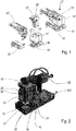
- Fig. 1 shows a prior art automatic crimping tool 10'.
- the crimping tool 10' comprises a ram assembly 12' moveably received in a guide block 14'.
- a crimping anvil 16' is arranged at a base 18' of the guide block 14' and is in reciprocal engagement with the ram assembly 12' on the vertical to and fro movement of the ram assembly 12' towards and away from the crimping anvil 16'.
- a terminal feeding unit 20' is provided to feed terminals 60, e.g. present at a strip cord 58 (see Fig. 6 ), to the crimping anvil 16'.
- the crimping tool 10' further comprises a feeder unit 22', such as a mechanic, pneumatic or hydraulic feeder unit 22' to drive the ram assembly 12' and to actuate a guiding of terminals 60 via the terminal feeding unit 20' to the crimping anvil 16'.
- a cable (not shown) can be connected to a respective terminal 60 placed at the crimping anvil 16'.
- the ram assembly 12' comprises a die assembly 24'.
- the die assembly 24' is shaped so as to connect a crimp portion of the terminal 60 to a conductor of the cable and optionally also an insulation crimp portion to an insulation of the cable at the crimping anvil 16'.
- the crimping anvil 16' is configured as a terminal support and shaped to hold the terminals 60 in a defined position until the end of the crimping process for a respective terminal 60.
- the die assembly 24' may also comprise means for separating the terminal 60 from the strip cord 58 via which it is supplied to the crimping anvil 16'.
- the ram assembly 12' further comprises a crimping head 26' via which at least one of a crimp height, an insulation height and a cutting height can be adapted in dependence on size and dimensions of the terminals 60 and the cables to be crimped one to another as well as the strip cord 58 in a manner known per se.
- the terminal feeding unit 20' is connected to the feeder unit 22' and their actions are synchronized in such a way that a new terminal 60 is fed to the crimping anvil 16' once a terminal 60 crimped to a cable is removed and the ram assembly 12' is moved away from the crimping anvil 16'.
- Fig. 2 shows a perspective view of a first embodiment of an automatic crimping tool 10.
- the automatic crimping tool 10 comprises a ram assembly 12 having four vertical sides 28 of which only two can be seen in Fig. 2 .
- the ram assembly 12 is configured to reciprocally move to and fro, i.e. down and up, between a crimping position and a position of rest.
- a tool 24 is arranged at each of the vertical sides 28. Each tool 24 is configured to cooperate with a respective crimping anvil 16 to crimp terminals 60 to respective components.
- each tool 24 preferably differs from the other three tools 24 arranged at the ram assembly 12 and that each tool 24 is adapted to deform terminals 60 of different shape and/or size in comparison to the other tools 24 arranged at the ram assembly 12 with respect to the component at the crimping anvil 16 to form a crimp.
- the crimping tool also comprises a feeder unit 22 adapted to drive the ram assembly 12.
- the feeder unit is driven pneumatically, it should be noted that the feeder unit 22 could also be driven hydraulically or by means of an electric motor.
- the crimping tool 10 of Fig. 2 comprises a terminal feeding unit 20 that is covered by the feeder unit 22 in the drawing shown.
- the actions of the terminal feeding unit 20 and of the feeder unit 22 are synchronized such that on an upward movement of the ram assembly 12, a new terminal is introduced a the crimping anvil 16 for a subsequent crimping action.
- the ram assembly 12 On operation of the crimping tool 10 the ram assembly 12 is configured to be moved such that only one of the plurality of tools 24 can occupy the crimping position in which one terminal 60 can be crimped to one component at a time, i.e. the automatic crimping tool 10 is configured to only use a respective one of the tools 24 during a crimping action.
- a rotatable disc 30 is arranged at the base 18, with a plurality of crimping anvils 16 being arranged at the rotatable disc 30.
- Each crimping anvil 16 is associated with one of the plurality of tools 24, i.e. a crimping anvil 16 is provided for each vertical side 28 of the ram assembly 12.
- Each crimping anvil 16 and its associated tool 24 can be moved, in particular rotated, into an active position forming part of the crimping position of the ram assembly 12 by means of the rotatable disc 30.
- the rotatable disc 30 is arranged at the base 18 and can be locked into a plurality of pre-defined positions at the base 18, i.e. the active position and the inactive positions.
- the active position corresponds to a position in which the crimping action can take place and that comprises the crimping position of the ram assembly 12.
- one of the plurality of tools 24 and its associated crimping anvil 16 can be brought so close to one another that the tool 24 deforms crimping portions 62, 64 of the terminal 60 (see Fig. 6 ) and crimps a conductor crimp portion 64 to the conductor of e.g. a component, such as a cable, and an insulting crimp portion 62 to an insulator of the cable.
- a lever 100 via which the rotatable disc 30 can be locked into one of the positions at the base 18.
- the rotatable disc 30 can be rotated to move one of the crimping anvils 16 from the inactive position into the active portion while moving the crimping anvil 16 previously present in the active position into an inactive position.
- Fig. 3 shows a perspective view of the ram assembly 12 of the automatic crimping tool 10 of Fig. 2 .
- the ram assembly 12 comprises the plurality of vertical sides 28 with each vertical side 28 comprising a mount 32 for a respective tool 24 for connecting terminals 60 to a component. In this way the tools 24 are configured as removable from said ram assembly 12.
- the plurality of mounts 32 can either be of identical design and size, or vary in their design and/or size in dependence on the tool 24, such as a die assembly (see Fig. 5 ) installed at the mount 32.
- the ram assembly 12 is connected to a crimping head 34 at the top end of Fig. 3 .
- the crimping head 34 comprises tool setting means 36, 38.
- the tool setting means 36, 38 can vary a position each of the tools 24 can adopt relative to the crimping anvil 16. In this connection only one tool setting means 36, 38 is provided that is configured to set a position of all of the tools 24 arranged at the ram assembly 12. In this connection it should be noted that tool setting means 36, 38 could be provided for each of the tools 24.
- the tool setting means 36, 38 can be configured to vary at least one of a crimp height, an insulation height and a cutting height in dependence on the size and dimensions of the terminals 60 and the cables to be crimped one to another.
- Each tool 24 differs from the other tools 24 of the plurality of tools 24 arranged at the ram assembly 12.
- Each tool is configured as a ram that is adapted to crimp the terminal 60 to the cable.
- the ram assembly 12 has an at least substantially polygonal outer shape.
- the ram assembly has a rectangular outer shape making up the four vertical sides 28 having the respective mount 32 for a respective tool 24 present there.
- the ram assembly 12 comprises a coupling portion 40 via which the ram assembly 12 can be coupled to the base 18.
- the coupling portion 40 also has a rectangular shape in a cross-section thereof.
- Fig. 4 shows a perspective view of the base 18 and the associated crimping anvils 16 of the automatic crimping tool 10 of Fig. 2 arranged at the rotatable disc 30.
- the base 18 further comprises a ram assembly receiver 42 formed at the rotatable disc 30 between and by the four crimping anvil receivers 44.
- the four crimping anvil receivers 44 can be of differing height and/or size, with walls of the coupling portion 40 likewise having differences in height and/or size.
- the different heights and/or sizes of the crimping anvil receivers 44 and of the coupling portion 40 can enable a coded alignment of the ram assembly 12 relative to the rotatable disc 30 such that each corresponding tool 24 is aligned with its associated crimping anvil 16.
- the ram assembly receiver 42 has an opening with an at least polygonal shape in a cross-section thereof, in the present instance an at least substantially square cross-section.
- the opening is configured to receive a correspondingly shaped part of the ram assembly 12, namely the coupling portion 40.
- connection elements 48 Individual components 46 of the crimping anvils 16 are connected to the respective crimping anvil receivers 44 by means of connection elements 48. In the present instance by a combination of a screw that engages a corresponding thread present at the crimping anvil receiver 44.
- the components 46 comprise a stationary terminal support surface adapted to support the terminal 60 during the crimping process, an insulation portion support surface adapted to support the part of the insulation to which the terminal 60 is crimped and a conductor portion support surface adapted to support the part of the conductor to which the terminal 60 is crimped.
- the ram assembly receiver 42 is configured to entrain the ram assembly via the coupling portion 40 such that the ram assembly 12 can be moved to move one of the tools 24 and its associated crimping anvil 16 from an inactive position into an active position.
- the tools 24 are moved by means of rotation of the rotatable disc 30.
- the automatic crimping tool 10 is configured to only use a respective one of the tools 24 during a crimping action.
- the automatic crimping tool 10 discussed in the foregoing can be installed in a plant (not shown) for the automated production of crimped cables, the plant comprising one or more such crimping tools 10 or a combination of crimping tools 10 with prior art crimping tools 10'.
- the plant can be semi-automatic, e.g. the cables are individually guided to the crimping tool 10 by means of personnel, on the other hand the plant can be fully automatic and the cables are guided to the respective crimping tool via a robot.
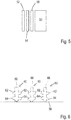
- Fig. 5 shows a schematic example of the tool 24, i.e. the die assembly as can be used in Fig. 2 .
- the tool 24 is composed of a ram 50 at which a wire guide 52, an insulator crimping plate 54 and a conductor crimping plate 56 are mounted, e.g. via screws (not shown).
- the wire guide 52 is configured to guide the cable to the terminal 60.
- the insulator crimping plate 54 is used to deform portions of the terminal 60 with respect to the insulator of the cable.
- the conductor crimping plate 56 is used to deform portions of the terminal 60 with respect to a conductor, i.e. the core, of a cable.
- the ram 50 is attachable to the ram assembly 12 and on the to and fro movement enables the crimping of the terminals 60 the respective components.
- the attachment of the ram 50 and the further parts of the die assembly to the ram assembly 12 can be made by way of grooves and/or fastener elements (both not shown) cooperating with corresponding members present at the ram assembly 12.
- a strip cutting tool that is used to separate a respectively crimped terminal 60 from the strip cord 58, so that the cable with the attached terminal 60 can be removed from the crimping tool 10 after a crimping process has taken place.
- Fig. 6 shows a schematic example of the strip cord 58 having the terminals 60 attached thereto.
- Each terminal 60 comprises the insulator crimp portion 62 used to crimp the terminal 60 to an insulator of a cable and the conductor crimp portion 64 used to crimp the terminal 60 to a conductor of a cable.
- a connector 66 is present at the free end of the terminal 60 and is configured to be connected to a further electric component (not shown).
- the lever 100 On making a change between the tools 24 of the automatic crimping tool 10, the lever 100 is set such that the rotatable disc 30 is moved into the unlocked position and can be rotated. Thereby the desired crimping anvil 16 and the associated tool 24can be rotated into the active position while a further currently non-desired crimping anvil 16 and its associated tool 24 are moved from the active position into an inactive position by means of a rotation. Thereafter, the lever is engaged again to lock the rotatable disc 30 in a locked position.
- a crimping action can take place due to the reciprocal movement of the ram assembly 12 to and away from the crimping anvil 16 between a crimping position in which a terminal is crimped to a cable and a position of rest in which no crimping takes place.
Landscapes
- Engineering & Computer Science (AREA)
- Manufacturing & Machinery (AREA)
- Manufacturing Of Electrical Connectors (AREA)
Abstract
Description
- The present invention relates to a crimping tool for connecting terminals to components, the crimping tool comprising a ram assembly; and a plurality of tools, with each tool being configured to cooperate with a crimping anvil to connect the terminals to respective components. The invention further relates to a respective base for a crimping tool, to a ram assembly for a crimping tool, to a plant for the automated production of wiring harnesses and to a method of changing between tools of a crimping tool.
- Crimping is the process of joining two or more components, such as pieces of metal or other ductile material to one another. The joint is formed by deforming one or more of the pieces to be joined. For example electrical terminals are joined to conductors of electric cables in order to use the terminal to connect the cable to an electronic installation. The terminal typically has a crimp portion that is arranged adjacent to the terminal. The crimp portion is designed to be deformed relative to the conductor of the electric cable to form an electrically conductive connection between the conductor and the terminal.
- Semi-automatic or automatic crimping tools require a specific die assembly for each type of terminal to be crimped. The terminal and the cable are placed at an anvil and a crimp portion is deformed towards the anvil by means of a press to produce the crimp in such crimping tools. Typically a separate die assembly and crimping anvil is provided for each size and shape of terminal that needs to be crimped, i.e. a specifically shaped tool is used for each type of terminal. Even for similar terminals one individual crimping die has to be used and installed at the crimping station which is demanding in effort and cost.
- Moreover, in a factory operated to e.g. produce electrical components, for example, wiring harnesses of vehicles, such as cars, various cables and terminals are connected one to another on the formation of the electrical components. Depending on the application of the terminal, the terminal and the associated cable have various sizes (diameters and lengths) adapted to the application. Each type of terminal and each size of cable requires its own crimping tool in order to produce the crimp, thus a plethora of tools is required for the individual cables of one and the same wiring harness.
- Setting up the automatic crimping tools such that they can crimp a certain type of terminal to a specific cable takes time and precision in order to ensure good quality joins, i.e. crimps.
- It is therefore an object of the present invention to make available a tool for crimping terminals that reduces the time required to change a tool for different terminals to be crimped. It is a further object of the invention to reduce the number of crimping stations required to crimp a plurality of various types of terminals in one plant. It is a further object of the invention to increase the efficiency of a plant adapted to crimping a plethora of terminals.
- This object is satisfied by a crimping tool for connecting terminals to components in accordance with claim 1. Advantageous designs of the crimping tool are discussed in the dependent claims and the following description.
- Such a crimping tool, in particular an automatic crimping tool, comprises: a ram assembly having a plurality of vertical sides, with the ram assembly being configured to reciprocally move to and fro between a crimping position and a position of rest; and a plurality of tools arranged at at least two of the vertical sides, with each tool being configured to cooperate with a crimping anvil to crimp the terminals to the respective components.
- In this way a crimping tool can be made available that is capable of crimping terminals of different shape and/or size with respect to the component at one and the same apparatus at different vertical sides of the apparatus.
- To date no crimping tool was available that comprised a ram assembly having a plurality of tools mounted thereon at different sides, with the different tools each being capable of processing terminals if in the crimping position. Moreover, the up time of the crimping tool is increased as the period between setting up the crimping tool and the calibration is reduced for the different tools. Moreover, a crimp process control is improved, since fewer crimping tools exist and the changeover between tools is made more simply and less costly with respect to time.
- Problems associated with a low efficiency of the plant due to changeovers having to occur between terminals of different size are overcome by simply moving the spare crimp tools into an active position and subsequently using these tools to connect terminals to components such as cables.
- Moreover, prior art crimping tools required a re-calibration if the ram assembly was removed, by not having to remove the ram assembly to switch between different tools, the crimping tool does not require a re-calibration on switching between different tools. On installing e.g. four or five tools at a rectangular or pentagonal shaped ram assembly and installing this at the crimping tool one calibration process can take place for four to five tools simultaneously cutting back on down time considerably and increasing the efficiency of a plant while simultaneously being able to reduce the number of crimping stations for the same number of tools.
- It is preferred if the crimping tool is an automatic crimping tool and if the crimping tool is configured to only use a respective one of the tools during a crimping action.
- Preferably each tool differs from the other tools of the plurality of tools and/or wherein only one tool is arranged at one of the vertical sides of the ram assembly. In this way one and the same ram assembly can be used for various terminals without requiring a recalibration of the ram assembly on switching between tools of the crimping tool.
- Advantageously the ram assembly has an at least substantially polygonal outer shape with vertical sides, preferably an at least substantially rectangular outer shape with four vertical sides, with each vertical side comprising one of a mount for a respective one of said tools or a respective one of said tools. Such shapes can be used to mount three, four, five six or more tools at one crimping station increasing the flexibility of the system. The crimping tool thereby allows the processing of e.g. 4 terminals at the same tool body without having to recalibrate the crimping tool between tool changes.
- It is preferred if the ram assembly is configured to be moved such that only one of the plurality of tools can occupy the crimping position in which one terminal can be crimped to one component at a time. This means that one only of the tools is in an active position in which it is capable of carrying out a crimping process at the same time. The remaining tools are inactive and thereby do not wear while present at the ram assembly.
- Preferably the crimping tool further comprises a rotatable disc, with a plurality of crimping anvils being arranged at the rotatable disc. A rotatable disc is an advantageous component to allow a swift change between tools. Providing the plurality of crimping anvils at the rotatable disc ensures that both the tool, i.e. the die assembly, and the anvil are adapted to the terminal and the component to be processed. It is preferred if the ram assembly is also arranged at the rotatable disc such that the crimping anvil can be moved together with the tools from an inactive position to an active position.
- Advantageously a respective crimping anvil is associated with a respective one of the plurality of tools, i.e. each tool is configured to interact with a specific one of the plurality of crimping anvils, and said respective crimping anvil and its associated tool can be moved, in particular rotated, into an active position forming part of the crimping position of the ram assembly by means of the rotatable disc. The provision of a respective crimping anvil for a respective tool ensures the correct combination of parts for carrying out a crimp at a specific size of terminal.
- It is preferred if at least one of the rotatable disc and the base comprises a ram assembly receiver adapted to receive a part of the ram assembly, with the ram assembly receiver optionally being configured to entrain the ram assembly such that the ram assembly can be moved to move one of the tools from an inactive position into an active position; and/or with the ram assembly receiver having an opening with an at least polygonal shape in a cross-section thereof, preferably an at least substantially square or rectangular cross-section, with the opening preferably being configured to receive a correspondingly shaped part of the ram assembly, in particular a coupling portion of the ram assembly.
- Forming the ram assembly receiver at one of the rotatable disc and the base ensures that the components that are moved, in particular rotated, on changing between tools can interact with one another. In this way a size of the crimping tool can be reduced while a rigidity of the crimping tool can be enhanced.
- Preferably the rotatable disc is arranged at a base and can be locked into a plurality of pre-defined positions at the base, wherein each pre-defined position corresponds to a position in which one of the plurality of tools and its associated crimping anvil can occupy the crimping position. Being able to lock the crimping tool into various positions ensures that the tool in use cannot accidentally be moved out of use.
- Preferably coding means, such as color coding means, can be provided at the crimping tool. Thereby the correct tool for the correct terminal can be installed in the active position at the crimping tool.
- Advantageously the tools are configured as removable from said ram assembly and the ram assembly comprises a plurality of mounts for said tools, with each one of the plurality of mounts preferably being of identical design, and/or with one mount preferably being provided at each vertical side. In this way one and the same ram assembly can be used for a plethora of tools when a change is made between tools at the ram assembly. Providing one tool per vertical side allows the crimping of terminals to one cable at a time.
- It is preferred if each tool comprises a die assembly, with each die assembly comprising at least one of a conductor crimping plate, an insulator crimping plate and a strip cutting tool. Such tools are advantageously used to carry out the crimping process.
- Preferably the ram assembly is connected to a crimping head comprising tool setting means by means of which tool setting means a position of each of the tools can be pre-defined relative to the crimping anvil and/or terminal, preferably wherein the tool setting means are configured to set a position of all of the tools arranged at the ram assembly. In this way one and the same crimping head can be used to calibrate the plurality of tools installed at the ram assembly.
- According to a further aspect the present invention relates to a base for a crimping tool, in particular in accordance with the teaching presented herein, the base comprising a plurality of crimping anvil receivers, a rotatable disc, and a ram assembly receiver, wherein the plurality of crimping anvil receivers and at least a part of the ram assembly receiver is formed at the rotatable disc. Such a base can advantageously be used in a crimping tool as described in the foregoing having a plurality of tools present thereat. For this reason the advantages discussed in the foregoing also hold true for the base.
- According to a further aspect the present invention relates to a ram assembly for a crimping tool, in particular in accordance with the teaching presented herein, the ram assembly comprising a plurality of vertical sides with each vertical side comprising a mount for a respective tool for connecting terminals to a component. Such a ram assembly can advantageously be used in a crimping tool as described in the foregoing having a plurality of tools present thereat. For this reason the advantages discussed in the foregoing also hold true for the ram assembly.
- According to a further aspect the present invention relates to a plant for the automated production of crimped cables, the plant comprising one or more crimping tools in accordance with the teaching presented herein. Such a plant has an increased output efficiency, as the downtimes between tool changes can be reduced significantly.
- According to yet a further aspect the present invention relates to a method of changing between tools of a crimping tool, preferably in accordance with the teaching presented herein, the crimping tool comprising a plurality of tools arranged at a ram assembly, the method comprising the step of moving the ram assembly to move a respective one of the plurality of tools from an inactive position - in which no crimping takes place - to an active position - in which a crimping action can take place, wherein the step of moving preferably comprises a rotating movement.
- Further embodiments of the invention are described in the following description of the Figures. The invention will be explained in the following in detail by means of embodiments and with reference to the drawing in which is shown:
- Fig. 1
- a view of a prior art crimping tool, as well as an exploded view of the individual components of the prior art crimping tool;
- Fig. 2
- a perspective view of a first embodiment of an automatic crimping tool;
- Fig. 3
- a perspective view of a ram assembly of the automatic crimping tool of
Fig. 2 ; - Fig. 4
- a perspective view of a base and associated crimping anvils of the automatic crimping tool of
Fig. 2 ; - Fig. 5
- a schematic example of a tool; and
- Fig. 6
- an example of a strip cord for guiding terminals.
- In the following the same reference numerals will be used for parts having the same or equivalent function. Any statements made having regard to the direction of a component are made relative to the position shown in the drawing and can naturally vary in the actual position of application.
-
Fig. 1 shows a prior art automatic crimping tool 10'. The crimping tool 10' comprises a ram assembly 12' moveably received in a guide block 14'. A crimping anvil 16' is arranged at a base 18' of the guide block 14' and is in reciprocal engagement with the ram assembly 12' on the vertical to and fro movement of the ram assembly 12' towards and away from the crimping anvil 16'. - A terminal feeding unit 20' is provided to feed
terminals 60, e.g. present at a strip cord 58 (seeFig. 6 ), to the crimping anvil 16'. The crimping tool 10' further comprises a feeder unit 22', such as a mechanic, pneumatic or hydraulic feeder unit 22' to drive the ram assembly 12' and to actuate a guiding ofterminals 60 via the terminal feeding unit 20' to the crimping anvil 16'. - On driving the ram assembly 12' towards the crimping anvil 16', a cable (not shown) can be connected to a
respective terminal 60 placed at the crimping anvil 16'. - For the purpose of crimping, the ram assembly 12' comprises a die assembly 24'. The die assembly 24' is shaped so as to connect a crimp portion of the terminal 60 to a conductor of the cable and optionally also an insulation crimp portion to an insulation of the cable at the crimping anvil 16'. The crimping anvil 16' is configured as a terminal support and shaped to hold the
terminals 60 in a defined position until the end of the crimping process for arespective terminal 60. - The die assembly 24' may also comprise means for separating the terminal 60 from the
strip cord 58 via which it is supplied to the crimping anvil 16'. - The ram assembly 12' further comprises a crimping head 26' via which at least one of a crimp height, an insulation height and a cutting height can be adapted in dependence on size and dimensions of the
terminals 60 and the cables to be crimped one to another as well as thestrip cord 58 in a manner known per se. - The terminal feeding unit 20' is connected to the feeder unit 22' and their actions are synchronized in such a way that a
new terminal 60 is fed to the crimping anvil 16' once a terminal 60 crimped to a cable is removed and the ram assembly 12' is moved away from the crimping anvil 16'. -
Fig. 2 shows a perspective view of a first embodiment of an automatic crimpingtool 10. The automatic crimpingtool 10 comprises aram assembly 12 having fourvertical sides 28 of which only two can be seen inFig. 2 . Theram assembly 12 is configured to reciprocally move to and fro, i.e. down and up, between a crimping position and a position of rest. Atool 24 is arranged at each of the vertical sides 28. Eachtool 24 is configured to cooperate with a respective crimpinganvil 16 to crimpterminals 60 to respective components. - It should be noted in this connection that each
tool 24 preferably differs from the other threetools 24 arranged at theram assembly 12 and that eachtool 24 is adapted to deformterminals 60 of different shape and/or size in comparison to theother tools 24 arranged at theram assembly 12 with respect to the component at the crimpinganvil 16 to form a crimp. - The crimping tool also comprises a
feeder unit 22 adapted to drive theram assembly 12. In the present instance the feeder unit is driven pneumatically, it should be noted that thefeeder unit 22 could also be driven hydraulically or by means of an electric motor. Like with the prior art crimping tool 10' ofFig. 1 the crimpingtool 10 ofFig. 2 comprises aterminal feeding unit 20 that is covered by thefeeder unit 22 in the drawing shown. - The actions of the
terminal feeding unit 20 and of thefeeder unit 22 are synchronized such that on an upward movement of theram assembly 12, a new terminal is introduced a the crimpinganvil 16 for a subsequent crimping action. - On operation of the crimping
tool 10 theram assembly 12 is configured to be moved such that only one of the plurality oftools 24 can occupy the crimping position in which oneterminal 60 can be crimped to one component at a time, i.e. the automatic crimpingtool 10 is configured to only use a respective one of thetools 24 during a crimping action. - A
rotatable disc 30 is arranged at thebase 18, with a plurality of crimpinganvils 16 being arranged at therotatable disc 30. Each crimpinganvil 16 is associated with one of the plurality oftools 24, i.e. a crimpinganvil 16 is provided for eachvertical side 28 of theram assembly 12. Each crimpinganvil 16 and its associatedtool 24 can be moved, in particular rotated, into an active position forming part of the crimping position of theram assembly 12 by means of therotatable disc 30. - The
rotatable disc 30 is arranged at thebase 18 and can be locked into a plurality of pre-defined positions at thebase 18, i.e. the active position and the inactive positions. The active position corresponds to a position in which the crimping action can take place and that comprises the crimping position of theram assembly 12. In the active position one of the plurality oftools 24 and its associated crimpinganvil 16 can be brought so close to one another that thetool 24 deforms crimpingportions Fig. 6 ) and crimps aconductor crimp portion 64 to the conductor of e.g. a component, such as a cable, and aninsulting crimp portion 62 to an insulator of the cable. - Further shown is a
lever 100 via which therotatable disc 30 can be locked into one of the positions at thebase 18. In the unlocked position therotatable disc 30 can be rotated to move one of the crimpinganvils 16 from the inactive position into the active portion while moving the crimpinganvil 16 previously present in the active position into an inactive position. -
Fig. 3 shows a perspective view of theram assembly 12 of the automatic crimpingtool 10 ofFig. 2 . Theram assembly 12 comprises the plurality ofvertical sides 28 with eachvertical side 28 comprising amount 32 for arespective tool 24 for connectingterminals 60 to a component. In this way thetools 24 are configured as removable from saidram assembly 12. - The plurality of
mounts 32 can either be of identical design and size, or vary in their design and/or size in dependence on thetool 24, such as a die assembly (seeFig. 5 ) installed at themount 32. - The
ram assembly 12 is connected to a crimpinghead 34 at the top end ofFig. 3 . The crimpinghead 34 comprises tool setting means 36, 38. The tool setting means 36, 38 can vary a position each of thetools 24 can adopt relative to the crimpinganvil 16. In this connection only one tool setting means 36, 38 is provided that is configured to set a position of all of thetools 24 arranged at theram assembly 12. In this connection it should be noted that tool setting means 36, 38 could be provided for each of thetools 24. - The tool setting means 36, 38 can be configured to vary at least one of a crimp height, an insulation height and a cutting height in dependence on the size and dimensions of the
terminals 60 and the cables to be crimped one to another. - Each
tool 24 differs from theother tools 24 of the plurality oftools 24 arranged at theram assembly 12. Each tool is configured as a ram that is adapted to crimp the terminal 60 to the cable. - The
ram assembly 12 has an at least substantially polygonal outer shape. In the example ofFigs. 2 to 4 the ram assembly has a rectangular outer shape making up the fourvertical sides 28 having therespective mount 32 for arespective tool 24 present there. - At the end of the
ram assembly 12 disposed opposite to the crimpinghead 34, theram assembly 12 comprises acoupling portion 40 via which theram assembly 12 can be coupled to thebase 18. Thecoupling portion 40 also has a rectangular shape in a cross-section thereof. -
Fig. 4 shows a perspective view of thebase 18 and the associated crimpinganvils 16 of the automatic crimpingtool 10 ofFig. 2 arranged at therotatable disc 30. The base 18 further comprises aram assembly receiver 42 formed at therotatable disc 30 between and by the four crimpinganvil receivers 44. The four crimpinganvil receivers 44 can be of differing height and/or size, with walls of thecoupling portion 40 likewise having differences in height and/or size. The different heights and/or sizes of the crimpinganvil receivers 44 and of thecoupling portion 40 can enable a coded alignment of theram assembly 12 relative to therotatable disc 30 such that eachcorresponding tool 24 is aligned with its associated crimpinganvil 16. - The
ram assembly receiver 42 has an opening with an at least polygonal shape in a cross-section thereof, in the present instance an at least substantially square cross-section. The opening is configured to receive a correspondingly shaped part of theram assembly 12, namely thecoupling portion 40. -
Individual components 46 of the crimpinganvils 16 are connected to the respective crimpinganvil receivers 44 by means ofconnection elements 48. In the present instance by a combination of a screw that engages a corresponding thread present at the crimpinganvil receiver 44. - The
components 46 comprise a stationary terminal support surface adapted to support the terminal 60 during the crimping process, an insulation portion support surface adapted to support the part of the insulation to which the terminal 60 is crimped and a conductor portion support surface adapted to support the part of the conductor to which the terminal 60 is crimped. - The
ram assembly receiver 42 is configured to entrain the ram assembly via thecoupling portion 40 such that theram assembly 12 can be moved to move one of thetools 24 and its associated crimpinganvil 16 from an inactive position into an active position. Thetools 24 are moved by means of rotation of therotatable disc 30. The automatic crimpingtool 10 is configured to only use a respective one of thetools 24 during a crimping action. - The automatic crimping
tool 10 discussed in the foregoing can be installed in a plant (not shown) for the automated production of crimped cables, the plant comprising one or more such crimpingtools 10 or a combination of crimpingtools 10 with prior art crimping tools 10'. The plant can be semi-automatic, e.g. the cables are individually guided to the crimpingtool 10 by means of personnel, on the other hand the plant can be fully automatic and the cables are guided to the respective crimping tool via a robot. -
Fig. 5 shows a schematic example of thetool 24, i.e. the die assembly as can be used inFig. 2 . Thetool 24 is composed of aram 50 at which awire guide 52, aninsulator crimping plate 54 and aconductor crimping plate 56 are mounted, e.g. via screws (not shown). Thewire guide 52 is configured to guide the cable to the terminal 60. Theinsulator crimping plate 54 is used to deform portions of the terminal 60 with respect to the insulator of the cable. Theconductor crimping plate 56 is used to deform portions of the terminal 60 with respect to a conductor, i.e. the core, of a cable. - The
ram 50 is attachable to theram assembly 12 and on the to and fro movement enables the crimping of theterminals 60 the respective components. The attachment of theram 50 and the further parts of the die assembly to theram assembly 12 can be made by way of grooves and/or fastener elements (both not shown) cooperating with corresponding members present at theram assembly 12. - Not shown, but likewise optionally available at the crimping
tool 10 is a strip cutting tool that is used to separate a respectively crimped terminal 60 from thestrip cord 58, so that the cable with the attached terminal 60 can be removed from the crimpingtool 10 after a crimping process has taken place. -
Fig. 6 shows a schematic example of thestrip cord 58 having theterminals 60 attached thereto. Each terminal 60 comprises theinsulator crimp portion 62 used to crimp the terminal 60 to an insulator of a cable and theconductor crimp portion 64 used to crimp the terminal 60 to a conductor of a cable. Aconnector 66 is present at the free end of the terminal 60 and is configured to be connected to a further electric component (not shown). - On making a change between the
tools 24 of the automatic crimpingtool 10, thelever 100 is set such that therotatable disc 30 is moved into the unlocked position and can be rotated. Thereby the desired crimpinganvil 16 and the associated tool 24can be rotated into the active position while a further currently non-desired crimpinganvil 16 and its associatedtool 24 are moved from the active position into an inactive position by means of a rotation. Thereafter, the lever is engaged again to lock therotatable disc 30 in a locked position. - In the active position a crimping action can take place due to the reciprocal movement of the
ram assembly 12 to and away from the crimpinganvil 16 between a crimping position in which a terminal is crimped to a cable and a position of rest in which no crimping takes place. -
- 10, 10'
- crimping tool, prior art crimping tool
- 12, 12'
- ram assembly, prior art ram assembly
- 14'
- prior art guide block
- 16, 16'
- crimping anvil, prior art crimping anvil
- 18, 18'
- base, prior art base
- 20, 20'
- terminal feeding unit, prior art terminal feeding unit
- 22, 22'
- feeder unit, prior art feeder unit
- 24, 24'
- tool, prior art tool
- 26'
- prior art crimping head
- 28
- vertical side
- 30
- rotatable disc
- 32
- mount
- 34
- crimping head
- 36
- tool setting means
- 38
- tool setting means
- 40
- coupling portion
- 42
- ram assembly receiver
- 44
- crimping anvil receiver
- 46
- components of 16
- 48
- fastener elements
- 50
- ram
- 52
- wire guide
- 54
- insulator crimping plate
- 56
- conductor crimping plate
- 58
- strip cord
- 60
- terminal
- 62
- insulator crimp portion
- 64
- conductor crimp portion
- 66
- connector
- 100
- lever
Claims (15)
- A crimping tool (10) for connecting terminals (60) to components, the crimping tool (10) comprising:a ram assembly (12) having a plurality of vertical sides (28) and the ram assembly (12) being configured to reciprocally move to and fro between a crimping position and a position of rest; anda plurality of tools (24) arranged at at least two of the vertical sides (28), with each tool (24) being configured to cooperate with a crimping anvil (16) to crimp the terminals (60) to the respective components.
- A crimping tool (10) in accordance with claim 1,
wherein each tool (24) differs from the other tools (24) of the plurality of tools (24); and/or
wherein only one tool (24) is arranged at one of the vertical sides (28) of the ram assembly (12). - A crimping tool (10) in accordance with claim 1 or claim 2, wherein the ram assembly (12) has an at least substantially polygonal outer shape forming the vertical sides (28), preferably an at least substantially rectangular outer shape with four vertical sides (28), with each vertical side (28) comprising one of a mount (32) for a respective one of said tools (24) or a respective one of said tools (24).
- A crimping tool (10) in accordance with at least one of the preceding claims,
wherein the ram assembly (12) is configured to be moved such that only one of the plurality of tools (24) can occupy the crimping position in which one terminal (60) can be crimped to one component at a time. - A crimping tool (10) in accordance with at least one of the preceding claims, further comprising a rotatable disc (30), with a plurality of crimping anvils (16) being arranged at the rotatable disc (30), and with the ram assembly (12) preferably being arranged at the rotatable disc (30)..
- A crimping tool (10) in accordance with claim 5, wherein a respective crimping anvil (16) is associated with a respective one of the plurality of tools (24) and said respective crimping anvil (16) and its associated tool (24) can be moved, in particular rotated, into an active position forming part of the crimping position of the ram assembly (12) by means of the rotatable disc (30).
- A crimping tool (10) in accordance with claim 5 or claim 6, wherein at least one of the rotatable disc (30) and a base (18) forming a support for the rotatable disc (30), comprises a ram assembly receiver (42) adapted to receive a part of the ram assembly (12), with the ram assembly receiver (42) optionally being configured to entrain the ram assembly (12) such that the ram assembly (12) can be moved to move one of the tools (24) from an inactive position into an active position; and/or with the ram assembly receiver (42) having an opening with an at least polygonal shape in a cross-section thereof, preferably an at least substantially square or rectangular cross-section, with the opening preferably being configured to receive a correspondingly shaped part of the ram assembly (12), in particular a coupling portion (40) of the ram assembly (12).
- A crimping tool (10) in accordance with one of claims 5 to 7,
wherein the rotatable disc (30) is arranged at a base (18) and can be locked into a plurality of pre-defined positions at the base (18), wherein each pre-defined position corresponds to a position in which one of the plurality of tools (24) and its associated crimping anvil (16) can occupy the crimping position. - A crimping tool (10) in accordance with at least one of the preceding claims, wherein the tools (24) are configured as removable from said ram assembly (12) and the ram assembly (12) comprises a plurality of mounts (32) for said tools (24), with each one of the plurality of mounts (32) preferably being of identical design, and/or with one mount (32) preferably being provided at each vertical side (28).
- A crimping tool (10) in accordance with at least one of the preceding claims, wherein each tool (24) comprises a die assembly, with each die assembly comprising at least one of a conductor crimping plate (56), an insulator crimping plate (54), a wire guide (52) and a strip cutting tool; and/or
wherein coding means, such as color coding means, are provided at the crimping tool (10). - A crimping tool (10) in accordance with at least one of the preceding claims, wherein the ram assembly (12) is connected to a crimping head (34) comprising tool setting means (36, 38) by means of which tool setting means (36, 38) a position of each of the tools (24) can be pre-defined relative to the crimping anvil (16) and/or terminal (60), preferably wherein the tool setting means (36, 38) are configured to set a position of all of the tools (24) arranged at the ram assembly (12).
- A base (30) for a crimping tool (10), in particular in accordance with at least one of the preceding claims,
the base (30) comprising a plurality of crimping anvil receivers (42), a rotatable disc (30), and a ram assembly receiver (42), wherein the plurality of crimping anvil receivers (42) and at least a part of the ram assembly receiver (42) is formed at the rotatable disc (30). - A ram assembly (12) for a crimping tool (10), in particular in accordance with at least one of the preceding claims,
the ram assembly (12) comprising a plurality of vertical sides (28) with each vertical side (28) comprising a mount (32) for a respective tool (24) for connecting terminals (60) to a component. - A plant for the automated production of crimped cables, the plant comprising one or more crimping tools (10) in accordance with at least one of the preceding claims.
- A method of changing between tools (24) of a crimping tool (10), preferably in accordance with at least one of the preceding claims, the crimping tool (10) comprising a plurality of tools (24) arranged at a ram assembly (12), the method comprising the step of moving the ram assembly (12) to move a respective one of the plurality of tools (24) from an inactive position - in which no crimping takes place - to an active position - in which a crimping action can take place, wherein the step of moving preferably comprises a rotating movement.
Priority Applications (1)
| Application Number | Priority Date | Filing Date | Title |
|---|---|---|---|
| EP18156061.6A EP3525299B1 (en) | 2018-02-09 | 2018-02-09 | Crimping tool, base, ram assembly, plant and method of changing between tools of a crimping tool |
Applications Claiming Priority (1)
| Application Number | Priority Date | Filing Date | Title |
|---|---|---|---|
| EP18156061.6A EP3525299B1 (en) | 2018-02-09 | 2018-02-09 | Crimping tool, base, ram assembly, plant and method of changing between tools of a crimping tool |
Publications (2)
| Publication Number | Publication Date |
|---|---|
| EP3525299A1 true EP3525299A1 (en) | 2019-08-14 |
| EP3525299B1 EP3525299B1 (en) | 2022-11-02 |
Family
ID=61189335
Family Applications (1)
| Application Number | Title | Priority Date | Filing Date |
|---|---|---|---|
| EP18156061.6A Active EP3525299B1 (en) | 2018-02-09 | 2018-02-09 | Crimping tool, base, ram assembly, plant and method of changing between tools of a crimping tool |
Country Status (1)
| Country | Link |
|---|---|
| EP (1) | EP3525299B1 (en) |
Citations (3)
| Publication number | Priority date | Publication date | Assignee | Title |
|---|---|---|---|---|
| FR2643514A1 (en) * | 1989-02-17 | 1990-08-24 | Ricard Claude | Methods and devices for mechanically crimping a connection component onto a wire |
| JP2002158074A (en) * | 2000-11-21 | 2002-05-31 | Union Machinery Co Ltd | Terminal crimping device and method |
| WO2015053284A1 (en) * | 2013-10-07 | 2015-04-16 | 矢崎総業株式会社 | Wire-harness-component transport device, terminal-crimp-wire production device, wire-harness-component transport method, and terminal-crimp-wire production method |
-
2018
- 2018-02-09 EP EP18156061.6A patent/EP3525299B1/en active Active
Patent Citations (3)
| Publication number | Priority date | Publication date | Assignee | Title |
|---|---|---|---|---|
| FR2643514A1 (en) * | 1989-02-17 | 1990-08-24 | Ricard Claude | Methods and devices for mechanically crimping a connection component onto a wire |
| JP2002158074A (en) * | 2000-11-21 | 2002-05-31 | Union Machinery Co Ltd | Terminal crimping device and method |
| WO2015053284A1 (en) * | 2013-10-07 | 2015-04-16 | 矢崎総業株式会社 | Wire-harness-component transport device, terminal-crimp-wire production device, wire-harness-component transport method, and terminal-crimp-wire production method |
Also Published As
| Publication number | Publication date |
|---|---|
| EP3525299B1 (en) | 2022-11-02 |
Similar Documents
| Publication | Publication Date | Title |
|---|---|---|
| US11355893B2 (en) | Terminal crimping method | |
| US10290989B2 (en) | Quick release feed guide and tool support for terminal applicator | |
| WO1997020363A1 (en) | Tools for crimping an electrical contact onto a conductor | |
| US4178675A (en) | Applicator for telephone connectors | |
| US20170033525A1 (en) | Terminal crimping device | |
| EP3525299B1 (en) | Crimping tool, base, ram assembly, plant and method of changing between tools of a crimping tool | |
| US4669162A (en) | Method and apparatus for rapidly stripping cable wires and crimping contacts thereon | |
| WO2017141866A1 (en) | Terminal crimping device, terminal crimping tool, and method for producing terminal-crimped electric wire | |
| GB2264885A (en) | A method for laying a wire in a junction box | |
| US4921440A (en) | Connector aggregate | |
| JP5722088B2 (en) | Cable assembly apparatus and cable assembly method | |
| US11283230B2 (en) | Device, method, and system for inverse crimping | |
| US5210942A (en) | Method for producing cable harnesses | |
| WO1996042127A1 (en) | Crimping tool | |
| EP3616279B1 (en) | Crimp tooling having guide surfaces | |
| US5369235A (en) | Process for manufacturing a contacting device, contacting device and its use | |
| WO2015171845A2 (en) | Quick release push feed guide and tool support for terminal applicator | |
| US20180183198A1 (en) | Crimp Indentor, Crimping Tool and Method of Producing a Crimp Indentor | |
| CN219329465U (en) | Full-automatic wire harness processing equipment | |
| CN220272937U (en) | Riveting jig for terminal wire | |
| US11223177B2 (en) | Terminal crimping device | |
| CN219247123U (en) | Eight-point crimping die | |
| JP2016143502A (en) | Terminal crimping apparatus | |
| JP2001297848A (en) | Terminal crimpimg device | |
| KR101491966B1 (en) | Terminal crimping zig |
Legal Events
| Date | Code | Title | Description |
|---|---|---|---|
| PUAI | Public reference made under article 153(3) epc to a published international application that has entered the european phase |
Free format text: ORIGINAL CODE: 0009012 |
|
| STAA | Information on the status of an ep patent application or granted ep patent |
Free format text: STATUS: THE APPLICATION HAS BEEN PUBLISHED |
|
| AK | Designated contracting states |
Kind code of ref document: A1 Designated state(s): AL AT BE BG CH CY CZ DE DK EE ES FI FR GB GR HR HU IE IS IT LI LT LU LV MC MK MT NL NO PL PT RO RS SE SI SK SM TR |
|
| AX | Request for extension of the european patent |
Extension state: BA ME |
|
| STAA | Information on the status of an ep patent application or granted ep patent |
Free format text: STATUS: REQUEST FOR EXAMINATION WAS MADE |
|
| 17P | Request for examination filed |
Effective date: 20200214 |
|
| RBV | Designated contracting states (corrected) |
Designated state(s): AL AT BE BG CH CY CZ DE DK EE ES FI FR GB GR HR HU IE IS IT LI LT LU LV MC MK MT NL NO PL PT RO RS SE SI SK SM TR |
|
| STAA | Information on the status of an ep patent application or granted ep patent |
Free format text: STATUS: EXAMINATION IS IN PROGRESS |
|
| 17Q | First examination report despatched |
Effective date: 20201204 |
|
| GRAP | Despatch of communication of intention to grant a patent |
Free format text: ORIGINAL CODE: EPIDOSNIGR1 |
|
| STAA | Information on the status of an ep patent application or granted ep patent |
Free format text: STATUS: GRANT OF PATENT IS INTENDED |
|
| INTG | Intention to grant announced |
Effective date: 20220303 |
|
| GRAJ | Information related to disapproval of communication of intention to grant by the applicant or resumption of examination proceedings by the epo deleted |
Free format text: ORIGINAL CODE: EPIDOSDIGR1 |
|
| STAA | Information on the status of an ep patent application or granted ep patent |
Free format text: STATUS: EXAMINATION IS IN PROGRESS |
|
| GRAP | Despatch of communication of intention to grant a patent |
Free format text: ORIGINAL CODE: EPIDOSNIGR1 |
|
| STAA | Information on the status of an ep patent application or granted ep patent |
Free format text: STATUS: GRANT OF PATENT IS INTENDED |
|
| INTC | Intention to grant announced (deleted) | ||
| INTG | Intention to grant announced |
Effective date: 20220707 |
|
| GRAS | Grant fee paid |
Free format text: ORIGINAL CODE: EPIDOSNIGR3 |
|
| GRAA | (expected) grant |
Free format text: ORIGINAL CODE: 0009210 |
|
| STAA | Information on the status of an ep patent application or granted ep patent |
Free format text: STATUS: THE PATENT HAS BEEN GRANTED |
|
| AK | Designated contracting states |
Kind code of ref document: B1 Designated state(s): AL AT BE BG CH CY CZ DE DK EE ES FI FR GB GR HR HU IE IS IT LI LT LU LV MC MK MT NL NO PL PT RO RS SE SI SK SM TR |
|
| REG | Reference to a national code |
Ref country code: GB Ref legal event code: FG4D |
|
| REG | Reference to a national code |
Ref country code: CH Ref legal event code: EP Ref country code: AT Ref legal event code: REF Ref document number: 1529455 Country of ref document: AT Kind code of ref document: T Effective date: 20221115 |
|
| REG | Reference to a national code |
Ref country code: DE Ref legal event code: R096 Ref document number: 602018042463 Country of ref document: DE |
|
| REG | Reference to a national code |
Ref country code: IE Ref legal event code: FG4D |
|
| REG | Reference to a national code |
Ref country code: LT Ref legal event code: MG9D |
|
| REG | Reference to a national code |
Ref country code: NL Ref legal event code: MP Effective date: 20221102 |
|
| RAP4 | Party data changed (patent owner data changed or rights of a patent transferred) |
Owner name: APTIV TECHNOLOGIES LIMITED |
|
| REG | Reference to a national code |
Ref country code: AT Ref legal event code: MK05 Ref document number: 1529455 Country of ref document: AT Kind code of ref document: T Effective date: 20221102 |
|
| PG25 | Lapsed in a contracting state [announced via postgrant information from national office to epo] |
Ref country code: SE Free format text: LAPSE BECAUSE OF FAILURE TO SUBMIT A TRANSLATION OF THE DESCRIPTION OR TO PAY THE FEE WITHIN THE PRESCRIBED TIME-LIMIT Effective date: 20221102 Ref country code: PT Free format text: LAPSE BECAUSE OF FAILURE TO SUBMIT A TRANSLATION OF THE DESCRIPTION OR TO PAY THE FEE WITHIN THE PRESCRIBED TIME-LIMIT Effective date: 20230302 Ref country code: NO Free format text: LAPSE BECAUSE OF FAILURE TO SUBMIT A TRANSLATION OF THE DESCRIPTION OR TO PAY THE FEE WITHIN THE PRESCRIBED TIME-LIMIT Effective date: 20230202 Ref country code: LT Free format text: LAPSE BECAUSE OF FAILURE TO SUBMIT A TRANSLATION OF THE DESCRIPTION OR TO PAY THE FEE WITHIN THE PRESCRIBED TIME-LIMIT Effective date: 20221102 Ref country code: FI Free format text: LAPSE BECAUSE OF FAILURE TO SUBMIT A TRANSLATION OF THE DESCRIPTION OR TO PAY THE FEE WITHIN THE PRESCRIBED TIME-LIMIT Effective date: 20221102 Ref country code: ES Free format text: LAPSE BECAUSE OF FAILURE TO SUBMIT A TRANSLATION OF THE DESCRIPTION OR TO PAY THE FEE WITHIN THE PRESCRIBED TIME-LIMIT Effective date: 20221102 Ref country code: AT Free format text: LAPSE BECAUSE OF FAILURE TO SUBMIT A TRANSLATION OF THE DESCRIPTION OR TO PAY THE FEE WITHIN THE PRESCRIBED TIME-LIMIT Effective date: 20221102 |
|
| PGFP | Annual fee paid to national office [announced via postgrant information from national office to epo] |
Ref country code: FR Payment date: 20230223 Year of fee payment: 6 |
|
| PG25 | Lapsed in a contracting state [announced via postgrant information from national office to epo] |
Ref country code: RS Free format text: LAPSE BECAUSE OF FAILURE TO SUBMIT A TRANSLATION OF THE DESCRIPTION OR TO PAY THE FEE WITHIN THE PRESCRIBED TIME-LIMIT Effective date: 20221102 Ref country code: PL Free format text: LAPSE BECAUSE OF FAILURE TO SUBMIT A TRANSLATION OF THE DESCRIPTION OR TO PAY THE FEE WITHIN THE PRESCRIBED TIME-LIMIT Effective date: 20221102 Ref country code: LV Free format text: LAPSE BECAUSE OF FAILURE TO SUBMIT A TRANSLATION OF THE DESCRIPTION OR TO PAY THE FEE WITHIN THE PRESCRIBED TIME-LIMIT Effective date: 20221102 Ref country code: IS Free format text: LAPSE BECAUSE OF FAILURE TO SUBMIT A TRANSLATION OF THE DESCRIPTION OR TO PAY THE FEE WITHIN THE PRESCRIBED TIME-LIMIT Effective date: 20230302 Ref country code: HR Free format text: LAPSE BECAUSE OF FAILURE TO SUBMIT A TRANSLATION OF THE DESCRIPTION OR TO PAY THE FEE WITHIN THE PRESCRIBED TIME-LIMIT Effective date: 20221102 Ref country code: GR Free format text: LAPSE BECAUSE OF FAILURE TO SUBMIT A TRANSLATION OF THE DESCRIPTION OR TO PAY THE FEE WITHIN THE PRESCRIBED TIME-LIMIT Effective date: 20230203 |
|
| PGFP | Annual fee paid to national office [announced via postgrant information from national office to epo] |
Ref country code: GB Payment date: 20230216 Year of fee payment: 6 Ref country code: DE Payment date: 20230127 Year of fee payment: 6 |
|
| P01 | Opt-out of the competence of the unified patent court (upc) registered |
Effective date: 20230424 |
|
| PG25 | Lapsed in a contracting state [announced via postgrant information from national office to epo] |
Ref country code: NL Free format text: LAPSE BECAUSE OF FAILURE TO SUBMIT A TRANSLATION OF THE DESCRIPTION OR TO PAY THE FEE WITHIN THE PRESCRIBED TIME-LIMIT Effective date: 20221102 |
|
| PG25 | Lapsed in a contracting state [announced via postgrant information from national office to epo] |
Ref country code: SM Free format text: LAPSE BECAUSE OF FAILURE TO SUBMIT A TRANSLATION OF THE DESCRIPTION OR TO PAY THE FEE WITHIN THE PRESCRIBED TIME-LIMIT Effective date: 20221102 Ref country code: RO Free format text: LAPSE BECAUSE OF FAILURE TO SUBMIT A TRANSLATION OF THE DESCRIPTION OR TO PAY THE FEE WITHIN THE PRESCRIBED TIME-LIMIT Effective date: 20221102 Ref country code: EE Free format text: LAPSE BECAUSE OF FAILURE TO SUBMIT A TRANSLATION OF THE DESCRIPTION OR TO PAY THE FEE WITHIN THE PRESCRIBED TIME-LIMIT Effective date: 20221102 Ref country code: DK Free format text: LAPSE BECAUSE OF FAILURE TO SUBMIT A TRANSLATION OF THE DESCRIPTION OR TO PAY THE FEE WITHIN THE PRESCRIBED TIME-LIMIT Effective date: 20221102 Ref country code: CZ Free format text: LAPSE BECAUSE OF FAILURE TO SUBMIT A TRANSLATION OF THE DESCRIPTION OR TO PAY THE FEE WITHIN THE PRESCRIBED TIME-LIMIT Effective date: 20221102 |
|
| REG | Reference to a national code |
Ref country code: DE Ref legal event code: R097 Ref document number: 602018042463 Country of ref document: DE |
|
| PG25 | Lapsed in a contracting state [announced via postgrant information from national office to epo] |
Ref country code: SK Free format text: LAPSE BECAUSE OF FAILURE TO SUBMIT A TRANSLATION OF THE DESCRIPTION OR TO PAY THE FEE WITHIN THE PRESCRIBED TIME-LIMIT Effective date: 20221102 Ref country code: AL Free format text: LAPSE BECAUSE OF FAILURE TO SUBMIT A TRANSLATION OF THE DESCRIPTION OR TO PAY THE FEE WITHIN THE PRESCRIBED TIME-LIMIT Effective date: 20221102 |
|
| PLBE | No opposition filed within time limit |
Free format text: ORIGINAL CODE: 0009261 |
|
| STAA | Information on the status of an ep patent application or granted ep patent |
Free format text: STATUS: NO OPPOSITION FILED WITHIN TIME LIMIT |
|
| PG25 | Lapsed in a contracting state [announced via postgrant information from national office to epo] |
Ref country code: MC Free format text: LAPSE BECAUSE OF FAILURE TO SUBMIT A TRANSLATION OF THE DESCRIPTION OR TO PAY THE FEE WITHIN THE PRESCRIBED TIME-LIMIT Effective date: 20221102 |
|
| REG | Reference to a national code |
Ref country code: CH Ref legal event code: PL |
|
| 26N | No opposition filed |
Effective date: 20230803 |
|
| REG | Reference to a national code |
Ref country code: BE Ref legal event code: MM Effective date: 20230228 |
|
| PG25 | Lapsed in a contracting state [announced via postgrant information from national office to epo] |
Ref country code: LU Free format text: LAPSE BECAUSE OF NON-PAYMENT OF DUE FEES Effective date: 20230209 Ref country code: LI Free format text: LAPSE BECAUSE OF NON-PAYMENT OF DUE FEES Effective date: 20230228 Ref country code: CH Free format text: LAPSE BECAUSE OF NON-PAYMENT OF DUE FEES Effective date: 20230228 |
|
| PG25 | Lapsed in a contracting state [announced via postgrant information from national office to epo] |
Ref country code: SI Free format text: LAPSE BECAUSE OF FAILURE TO SUBMIT A TRANSLATION OF THE DESCRIPTION OR TO PAY THE FEE WITHIN THE PRESCRIBED TIME-LIMIT Effective date: 20221102 |
|
| REG | Reference to a national code |
Ref country code: IE Ref legal event code: MM4A |
|
| PG25 | Lapsed in a contracting state [announced via postgrant information from national office to epo] |
Ref country code: IE Free format text: LAPSE BECAUSE OF NON-PAYMENT OF DUE FEES Effective date: 20230209 |
|
| PG25 | Lapsed in a contracting state [announced via postgrant information from national office to epo] |
Ref country code: BE Free format text: LAPSE BECAUSE OF NON-PAYMENT OF DUE FEES Effective date: 20230228 |
|
| PG25 | Lapsed in a contracting state [announced via postgrant information from national office to epo] |
Ref country code: IT Free format text: LAPSE BECAUSE OF FAILURE TO SUBMIT A TRANSLATION OF THE DESCRIPTION OR TO PAY THE FEE WITHIN THE PRESCRIBED TIME-LIMIT Effective date: 20221102 |
|
| REG | Reference to a national code |
Ref country code: DE Ref legal event code: R119 Ref document number: 602018042463 Country of ref document: DE |
|
| GBPC | Gb: european patent ceased through non-payment of renewal fee |
Effective date: 20240209 |
|
| PG25 | Lapsed in a contracting state [announced via postgrant information from national office to epo] |
Ref country code: BG Free format text: LAPSE BECAUSE OF FAILURE TO SUBMIT A TRANSLATION OF THE DESCRIPTION OR TO PAY THE FEE WITHIN THE PRESCRIBED TIME-LIMIT Effective date: 20221102 |
|
| PG25 | Lapsed in a contracting state [announced via postgrant information from national office to epo] |
Ref country code: BG Free format text: LAPSE BECAUSE OF FAILURE TO SUBMIT A TRANSLATION OF THE DESCRIPTION OR TO PAY THE FEE WITHIN THE PRESCRIBED TIME-LIMIT Effective date: 20221102 |
|
| PG25 | Lapsed in a contracting state [announced via postgrant information from national office to epo] |
Ref country code: DE Free format text: LAPSE BECAUSE OF NON-PAYMENT OF DUE FEES Effective date: 20240903 |
|
| PG25 | Lapsed in a contracting state [announced via postgrant information from national office to epo] |
Ref country code: GB Free format text: LAPSE BECAUSE OF NON-PAYMENT OF DUE FEES Effective date: 20240209 |
|
| PG25 | Lapsed in a contracting state [announced via postgrant information from national office to epo] |
Ref country code: FR Free format text: LAPSE BECAUSE OF NON-PAYMENT OF DUE FEES Effective date: 20240229 |
|
| PG25 | Lapsed in a contracting state [announced via postgrant information from national office to epo] |
Ref country code: GB Free format text: LAPSE BECAUSE OF NON-PAYMENT OF DUE FEES Effective date: 20240209 Ref country code: FR Free format text: LAPSE BECAUSE OF NON-PAYMENT OF DUE FEES Effective date: 20240229 Ref country code: DE Free format text: LAPSE BECAUSE OF NON-PAYMENT OF DUE FEES Effective date: 20240903 |
|
| PG25 | Lapsed in a contracting state [announced via postgrant information from national office to epo] |
Ref country code: CY Free format text: LAPSE BECAUSE OF FAILURE TO SUBMIT A TRANSLATION OF THE DESCRIPTION OR TO PAY THE FEE WITHIN THE PRESCRIBED TIME-LIMIT; INVALID AB INITIO Effective date: 20180209 |
|
| PG25 | Lapsed in a contracting state [announced via postgrant information from national office to epo] |
Ref country code: HU Free format text: LAPSE BECAUSE OF FAILURE TO SUBMIT A TRANSLATION OF THE DESCRIPTION OR TO PAY THE FEE WITHIN THE PRESCRIBED TIME-LIMIT; INVALID AB INITIO Effective date: 20180209 |
|
| PG25 | Lapsed in a contracting state [announced via postgrant information from national office to epo] |
Ref country code: TR Free format text: LAPSE BECAUSE OF FAILURE TO SUBMIT A TRANSLATION OF THE DESCRIPTION OR TO PAY THE FEE WITHIN THE PRESCRIBED TIME-LIMIT Effective date: 20221102 |