EP3525296A1 - Electrical connection unit and battery system - Google Patents
Electrical connection unit and battery system Download PDFInfo
- Publication number
- EP3525296A1 EP3525296A1 EP19155463.3A EP19155463A EP3525296A1 EP 3525296 A1 EP3525296 A1 EP 3525296A1 EP 19155463 A EP19155463 A EP 19155463A EP 3525296 A1 EP3525296 A1 EP 3525296A1
- Authority
- EP
- European Patent Office
- Prior art keywords
- electrical
- terminal
- connection unit
- electrical connection
- fluidic
- Prior art date
- Legal status (The legal status is an assumption and is not a legal conclusion. Google has not performed a legal analysis and makes no representation as to the accuracy of the status listed.)
- Withdrawn
Links
Images



Classifications
-
- H—ELECTRICITY
- H01—ELECTRIC ELEMENTS
- H01R—ELECTRICALLY-CONDUCTIVE CONNECTIONS; STRUCTURAL ASSOCIATIONS OF A PLURALITY OF MUTUALLY-INSULATED ELECTRICAL CONNECTING ELEMENTS; COUPLING DEVICES; CURRENT COLLECTORS
- H01R11/00—Individual connecting elements providing two or more spaced connecting locations for conductive members which are, or may be, thereby interconnected, e.g. end pieces for wires or cables supported by the wire or cable and having means for facilitating electrical connection to some other wire, terminal, or conductive member, blocks of binding posts
- H01R11/11—End pieces or tapping pieces for wires, supported by the wire and for facilitating electrical connection to some other wire, terminal or conductive member
- H01R11/28—End pieces consisting of a ferrule or sleeve
- H01R11/281—End pieces consisting of a ferrule or sleeve for connections to batteries
- H01R11/283—Bolt, screw or threaded ferrule parallel to the battery post
-
- B—PERFORMING OPERATIONS; TRANSPORTING
- B60—VEHICLES IN GENERAL
- B60L—PROPULSION OF ELECTRICALLY-PROPELLED VEHICLES; SUPPLYING ELECTRIC POWER FOR AUXILIARY EQUIPMENT OF ELECTRICALLY-PROPELLED VEHICLES; ELECTRODYNAMIC BRAKE SYSTEMS FOR VEHICLES IN GENERAL; MAGNETIC SUSPENSION OR LEVITATION FOR VEHICLES; MONITORING OPERATING VARIABLES OF ELECTRICALLY-PROPELLED VEHICLES; ELECTRIC SAFETY DEVICES FOR ELECTRICALLY-PROPELLED VEHICLES
- B60L53/00—Methods of charging batteries, specially adapted for electric vehicles; Charging stations or on-board charging equipment therefor; Exchange of energy storage elements in electric vehicles
- B60L53/10—Methods of charging batteries, specially adapted for electric vehicles; Charging stations or on-board charging equipment therefor; Exchange of energy storage elements in electric vehicles characterised by the energy transfer between the charging station and the vehicle
- B60L53/14—Conductive energy transfer
- B60L53/16—Connectors, e.g. plugs or sockets, specially adapted for charging electric vehicles
-
- B—PERFORMING OPERATIONS; TRANSPORTING
- B60—VEHICLES IN GENERAL
- B60L—PROPULSION OF ELECTRICALLY-PROPELLED VEHICLES; SUPPLYING ELECTRIC POWER FOR AUXILIARY EQUIPMENT OF ELECTRICALLY-PROPELLED VEHICLES; ELECTRODYNAMIC BRAKE SYSTEMS FOR VEHICLES IN GENERAL; MAGNETIC SUSPENSION OR LEVITATION FOR VEHICLES; MONITORING OPERATING VARIABLES OF ELECTRICALLY-PROPELLED VEHICLES; ELECTRIC SAFETY DEVICES FOR ELECTRICALLY-PROPELLED VEHICLES
- B60L53/00—Methods of charging batteries, specially adapted for electric vehicles; Charging stations or on-board charging equipment therefor; Exchange of energy storage elements in electric vehicles
- B60L53/10—Methods of charging batteries, specially adapted for electric vehicles; Charging stations or on-board charging equipment therefor; Exchange of energy storage elements in electric vehicles characterised by the energy transfer between the charging station and the vehicle
- B60L53/14—Conductive energy transfer
- B60L53/18—Cables specially adapted for charging electric vehicles
-
- B—PERFORMING OPERATIONS; TRANSPORTING
- B60—VEHICLES IN GENERAL
- B60L—PROPULSION OF ELECTRICALLY-PROPELLED VEHICLES; SUPPLYING ELECTRIC POWER FOR AUXILIARY EQUIPMENT OF ELECTRICALLY-PROPELLED VEHICLES; ELECTRODYNAMIC BRAKE SYSTEMS FOR VEHICLES IN GENERAL; MAGNETIC SUSPENSION OR LEVITATION FOR VEHICLES; MONITORING OPERATING VARIABLES OF ELECTRICALLY-PROPELLED VEHICLES; ELECTRIC SAFETY DEVICES FOR ELECTRICALLY-PROPELLED VEHICLES
- B60L53/00—Methods of charging batteries, specially adapted for electric vehicles; Charging stations or on-board charging equipment therefor; Exchange of energy storage elements in electric vehicles
- B60L53/30—Constructional details of charging stations
- B60L53/302—Cooling of charging equipment
-
- H—ELECTRICITY
- H01—ELECTRIC ELEMENTS
- H01B—CABLES; CONDUCTORS; INSULATORS; SELECTION OF MATERIALS FOR THEIR CONDUCTIVE, INSULATING OR DIELECTRIC PROPERTIES
- H01B7/00—Insulated conductors or cables characterised by their form
- H01B7/0009—Details relating to the conductive cores
-
- H—ELECTRICITY
- H01—ELECTRIC ELEMENTS
- H01B—CABLES; CONDUCTORS; INSULATORS; SELECTION OF MATERIALS FOR THEIR CONDUCTIVE, INSULATING OR DIELECTRIC PROPERTIES
- H01B7/00—Insulated conductors or cables characterised by their form
- H01B7/42—Insulated conductors or cables characterised by their form with arrangements for heat dissipation or conduction
- H01B7/421—Insulated conductors or cables characterised by their form with arrangements for heat dissipation or conduction for heat dissipation
- H01B7/423—Insulated conductors or cables characterised by their form with arrangements for heat dissipation or conduction for heat dissipation using a cooling fluid
-
- H—ELECTRICITY
- H01—ELECTRIC ELEMENTS
- H01M—PROCESSES OR MEANS, e.g. BATTERIES, FOR THE DIRECT CONVERSION OF CHEMICAL ENERGY INTO ELECTRICAL ENERGY
- H01M50/00—Constructional details or processes of manufacture of the non-active parts of electrochemical cells other than fuel cells, e.g. hybrid cells
- H01M50/50—Current conducting connections for cells or batteries
-
- H—ELECTRICITY
- H01—ELECTRIC ELEMENTS
- H01R—ELECTRICALLY-CONDUCTIVE CONNECTIONS; STRUCTURAL ASSOCIATIONS OF A PLURALITY OF MUTUALLY-INSULATED ELECTRICAL CONNECTING ELEMENTS; COUPLING DEVICES; CURRENT COLLECTORS
- H01R11/00—Individual connecting elements providing two or more spaced connecting locations for conductive members which are, or may be, thereby interconnected, e.g. end pieces for wires or cables supported by the wire or cable and having means for facilitating electrical connection to some other wire, terminal, or conductive member, blocks of binding posts
- H01R11/11—End pieces or tapping pieces for wires, supported by the wire and for facilitating electrical connection to some other wire, terminal or conductive member
- H01R11/26—End pieces terminating in a screw clamp, screw or nut
-
- H—ELECTRICITY
- H01—ELECTRIC ELEMENTS
- H01R—ELECTRICALLY-CONDUCTIVE CONNECTIONS; STRUCTURAL ASSOCIATIONS OF A PLURALITY OF MUTUALLY-INSULATED ELECTRICAL CONNECTING ELEMENTS; COUPLING DEVICES; CURRENT COLLECTORS
- H01R11/00—Individual connecting elements providing two or more spaced connecting locations for conductive members which are, or may be, thereby interconnected, e.g. end pieces for wires or cables supported by the wire or cable and having means for facilitating electrical connection to some other wire, terminal, or conductive member, blocks of binding posts
- H01R11/11—End pieces or tapping pieces for wires, supported by the wire and for facilitating electrical connection to some other wire, terminal or conductive member
- H01R11/28—End pieces consisting of a ferrule or sleeve
- H01R11/281—End pieces consisting of a ferrule or sleeve for connections to batteries
- H01R11/285—Battery post and cable secured by the same locking means
-
- H—ELECTRICITY
- H01—ELECTRIC ELEMENTS
- H01R—ELECTRICALLY-CONDUCTIVE CONNECTIONS; STRUCTURAL ASSOCIATIONS OF A PLURALITY OF MUTUALLY-INSULATED ELECTRICAL CONNECTING ELEMENTS; COUPLING DEVICES; CURRENT COLLECTORS
- H01R13/00—Details of coupling devices of the kinds covered by groups H01R12/70 or H01R24/00 - H01R33/00
- H01R13/005—Electrical coupling combined with fluidic coupling
-
- H—ELECTRICITY
- H01—ELECTRIC ELEMENTS
- H01R—ELECTRICALLY-CONDUCTIVE CONNECTIONS; STRUCTURAL ASSOCIATIONS OF A PLURALITY OF MUTUALLY-INSULATED ELECTRICAL CONNECTING ELEMENTS; COUPLING DEVICES; CURRENT COLLECTORS
- H01R13/00—Details of coupling devices of the kinds covered by groups H01R12/70 or H01R24/00 - H01R33/00
- H01R13/46—Bases; Cases
- H01R13/533—Bases, cases made for use in extreme conditions, e.g. high temperature, radiation, vibration, corrosive environment, pressure
-
- H—ELECTRICITY
- H01—ELECTRIC ELEMENTS
- H01R—ELECTRICALLY-CONDUCTIVE CONNECTIONS; STRUCTURAL ASSOCIATIONS OF A PLURALITY OF MUTUALLY-INSULATED ELECTRICAL CONNECTING ELEMENTS; COUPLING DEVICES; CURRENT COLLECTORS
- H01R24/00—Two-part coupling devices, or either of their cooperating parts, characterised by their overall structure
- H01R24/58—Contacts spaced along longitudinal axis of engagement
-
- H—ELECTRICITY
- H01—ELECTRIC ELEMENTS
- H01R—ELECTRICALLY-CONDUCTIVE CONNECTIONS; STRUCTURAL ASSOCIATIONS OF A PLURALITY OF MUTUALLY-INSULATED ELECTRICAL CONNECTING ELEMENTS; COUPLING DEVICES; CURRENT COLLECTORS
- H01R4/00—Electrically-conductive connections between two or more conductive members in direct contact, i.e. touching one another; Means for effecting or maintaining such contact; Electrically-conductive connections having two or more spaced connecting locations for conductors and using contact members penetrating insulation
- H01R4/10—Electrically-conductive connections between two or more conductive members in direct contact, i.e. touching one another; Means for effecting or maintaining such contact; Electrically-conductive connections having two or more spaced connecting locations for conductors and using contact members penetrating insulation effected solely by twisting, wrapping, bending, crimping, or other permanent deformation
- H01R4/18—Electrically-conductive connections between two or more conductive members in direct contact, i.e. touching one another; Means for effecting or maintaining such contact; Electrically-conductive connections having two or more spaced connecting locations for conductors and using contact members penetrating insulation effected solely by twisting, wrapping, bending, crimping, or other permanent deformation by crimping
- H01R4/20—Electrically-conductive connections between two or more conductive members in direct contact, i.e. touching one another; Means for effecting or maintaining such contact; Electrically-conductive connections having two or more spaced connecting locations for conductors and using contact members penetrating insulation effected solely by twisting, wrapping, bending, crimping, or other permanent deformation by crimping using a crimping sleeve
-
- H—ELECTRICITY
- H01—ELECTRIC ELEMENTS
- H01R—ELECTRICALLY-CONDUCTIVE CONNECTIONS; STRUCTURAL ASSOCIATIONS OF A PLURALITY OF MUTUALLY-INSULATED ELECTRICAL CONNECTING ELEMENTS; COUPLING DEVICES; CURRENT COLLECTORS
- H01R4/00—Electrically-conductive connections between two or more conductive members in direct contact, i.e. touching one another; Means for effecting or maintaining such contact; Electrically-conductive connections having two or more spaced connecting locations for conductors and using contact members penetrating insulation
- H01R4/28—Clamped connections, spring connections
- H01R4/30—Clamped connections, spring connections utilising a screw or nut clamping member
-
- H—ELECTRICITY
- H05—ELECTRIC TECHNIQUES NOT OTHERWISE PROVIDED FOR
- H05K—PRINTED CIRCUITS; CASINGS OR CONSTRUCTIONAL DETAILS OF ELECTRIC APPARATUS; MANUFACTURE OF ASSEMBLAGES OF ELECTRICAL COMPONENTS
- H05K7/00—Constructional details common to different types of electric apparatus
- H05K7/20—Modifications to facilitate cooling, ventilating, or heating
- H05K7/2039—Modifications to facilitate cooling, ventilating, or heating characterised by the heat transfer by conduction from the heat generating element to a dissipating body
-
- H—ELECTRICITY
- H01—ELECTRIC ELEMENTS
- H01M—PROCESSES OR MEANS, e.g. BATTERIES, FOR THE DIRECT CONVERSION OF CHEMICAL ENERGY INTO ELECTRICAL ENERGY
- H01M2220/00—Batteries for particular applications
- H01M2220/20—Batteries in motive systems, e.g. vehicle, ship, plane
-
- H—ELECTRICITY
- H01—ELECTRIC ELEMENTS
- H01R—ELECTRICALLY-CONDUCTIVE CONNECTIONS; STRUCTURAL ASSOCIATIONS OF A PLURALITY OF MUTUALLY-INSULATED ELECTRICAL CONNECTING ELEMENTS; COUPLING DEVICES; CURRENT COLLECTORS
- H01R2201/00—Connectors or connections adapted for particular applications
- H01R2201/26—Connectors or connections adapted for particular applications for vehicles
-
- Y—GENERAL TAGGING OF NEW TECHNOLOGICAL DEVELOPMENTS; GENERAL TAGGING OF CROSS-SECTIONAL TECHNOLOGIES SPANNING OVER SEVERAL SECTIONS OF THE IPC; TECHNICAL SUBJECTS COVERED BY FORMER USPC CROSS-REFERENCE ART COLLECTIONS [XRACs] AND DIGESTS
- Y02—TECHNOLOGIES OR APPLICATIONS FOR MITIGATION OR ADAPTATION AGAINST CLIMATE CHANGE
- Y02E—REDUCTION OF GREENHOUSE GAS [GHG] EMISSIONS, RELATED TO ENERGY GENERATION, TRANSMISSION OR DISTRIBUTION
- Y02E60/00—Enabling technologies; Technologies with a potential or indirect contribution to GHG emissions mitigation
- Y02E60/10—Energy storage using batteries
-
- Y—GENERAL TAGGING OF NEW TECHNOLOGICAL DEVELOPMENTS; GENERAL TAGGING OF CROSS-SECTIONAL TECHNOLOGIES SPANNING OVER SEVERAL SECTIONS OF THE IPC; TECHNICAL SUBJECTS COVERED BY FORMER USPC CROSS-REFERENCE ART COLLECTIONS [XRACs] AND DIGESTS
- Y02—TECHNOLOGIES OR APPLICATIONS FOR MITIGATION OR ADAPTATION AGAINST CLIMATE CHANGE
- Y02T—CLIMATE CHANGE MITIGATION TECHNOLOGIES RELATED TO TRANSPORTATION
- Y02T10/00—Road transport of goods or passengers
- Y02T10/60—Other road transportation technologies with climate change mitigation effect
- Y02T10/70—Energy storage systems for electromobility, e.g. batteries
-
- Y—GENERAL TAGGING OF NEW TECHNOLOGICAL DEVELOPMENTS; GENERAL TAGGING OF CROSS-SECTIONAL TECHNOLOGIES SPANNING OVER SEVERAL SECTIONS OF THE IPC; TECHNICAL SUBJECTS COVERED BY FORMER USPC CROSS-REFERENCE ART COLLECTIONS [XRACs] AND DIGESTS
- Y02—TECHNOLOGIES OR APPLICATIONS FOR MITIGATION OR ADAPTATION AGAINST CLIMATE CHANGE
- Y02T—CLIMATE CHANGE MITIGATION TECHNOLOGIES RELATED TO TRANSPORTATION
- Y02T10/00—Road transport of goods or passengers
- Y02T10/60—Other road transportation technologies with climate change mitigation effect
- Y02T10/7072—Electromobility specific charging systems or methods for batteries, ultracapacitors, supercapacitors or double-layer capacitors
-
- Y—GENERAL TAGGING OF NEW TECHNOLOGICAL DEVELOPMENTS; GENERAL TAGGING OF CROSS-SECTIONAL TECHNOLOGIES SPANNING OVER SEVERAL SECTIONS OF THE IPC; TECHNICAL SUBJECTS COVERED BY FORMER USPC CROSS-REFERENCE ART COLLECTIONS [XRACs] AND DIGESTS
- Y02—TECHNOLOGIES OR APPLICATIONS FOR MITIGATION OR ADAPTATION AGAINST CLIMATE CHANGE
- Y02T—CLIMATE CHANGE MITIGATION TECHNOLOGIES RELATED TO TRANSPORTATION
- Y02T90/00—Enabling technologies or technologies with a potential or indirect contribution to GHG emissions mitigation
- Y02T90/10—Technologies relating to charging of electric vehicles
- Y02T90/12—Electric charging stations
-
- Y—GENERAL TAGGING OF NEW TECHNOLOGICAL DEVELOPMENTS; GENERAL TAGGING OF CROSS-SECTIONAL TECHNOLOGIES SPANNING OVER SEVERAL SECTIONS OF THE IPC; TECHNICAL SUBJECTS COVERED BY FORMER USPC CROSS-REFERENCE ART COLLECTIONS [XRACs] AND DIGESTS
- Y02—TECHNOLOGIES OR APPLICATIONS FOR MITIGATION OR ADAPTATION AGAINST CLIMATE CHANGE
- Y02T—CLIMATE CHANGE MITIGATION TECHNOLOGIES RELATED TO TRANSPORTATION
- Y02T90/00—Enabling technologies or technologies with a potential or indirect contribution to GHG emissions mitigation
- Y02T90/10—Technologies relating to charging of electric vehicles
- Y02T90/14—Plug-in electric vehicles
Definitions
- the present invention relates to an electrical connection unit with integrated cooling and to a battery system, which has such a connection unit.
- the cooling can be achieved by means of a liquid coolant.
- thermoelectric cooling there are various techniques for cooling electrical assemblies, for example air cooling using fans or thermoelectric cooling, which is based on the Peltier effect.
- Conventional air cooling systems with fans are limited in their capacity to dissipate heat. They are therefore suitable only to a limited extent for use with battery systems. It is substantially more efficient to discharge heat via a fluid, for example a cooling liquid such as water or an oil.
- a device for cooling a plug connection is known from DE 10 2015 221 571 A1 , which device is composed of a charging plug, a contact bushing, which is suitable for receiving the charging plug, a first electrical line which is connected to the contact bushing and a second electrical line which is connected to the charging plug, wherein the first electrical line has a first cavity and/or the second electrical line has a second cavity along the electrical line, via which a coolant is conducted.
- a tube, which surrounds the charging cable has a coolant flow through it. This coolant can be air, oil, water or another fluid suitable for dissipating heat.
- the inventors of the present invention have realised that the concept of liquid cooling of an electrical line can be adapted for use in a battery system, if the electrical terminal at the battery can be configured such that it can likewise have the cooling medium flow through it, at least partly.
- the present invention provides an electrical connection unit which, on the one hand, can be connected to a contact of a battery, and on the other hand to a corresponding external contact.
- the electrical connection unit comprises a first electrical terminal for contacting a first electrical component, for example a battery, and a second electrical terminal, which is connected to an electrically conductive cable, wherein the electrical connection unit establishes an electrical connection between the first electrical terminal and the second electrical terminal.
- the electrical connection unit comprises a first fluidic terminal for attaching a coolant source.
- the second electrical terminal moreover, is formed as a second fluidic terminal, such that it connects a cooling channel, which is arranged on the cable and through which a coolant for cooling the electrically conductive cable can flow, to the first fluidic terminal.
- connection unit thus serves to attach to both the electrical current circuit and to the coolant circuit.
- the cable comprises an electrically conductive material, which forms a cavity which is surrounded by an insulator, wherein the cooling channel is formed in the interior of the cavity formed by the electrically conductive material.
- the second electrical terminal is arranged at a ring coupler, wherein the ring coupler holds the second terminal rotatably around a longitudinal axis of the first electrical terminal.
- the rotatability of the ring coupler can be blocked after mounting on the first electrical component, for example, by a force fit of the inventive electrical connection unit. In other words, the rotatability exists only during the mounting, while the location of the cable is fixed in the finally mounted state. If the connection between the first electrical terminal and the first electrical component is releasable, it can be provided that the rotatability is allowed again mechanically by releasing the electrical connection.
- Ring support couplers for fluids are known, for example, from EP0 646 748 B1 and are used if fluid lines, which can lie in any desired angular positions in relation to each other, have to be connected to each other.
- the basic form of the screw is a hollow cylinder, which is closed at the head end of the screw and open at the thread end. Furthermore, at the head end, the screw has two holes lying opposite each other.
- the ring terminal is composed of a ring which has a hole on one side, onto which a terminal support is placed, in such a way that the support points outwards in the radial direction.
- the ring terminal is plugged onto the hollow screw between two sealing rings. In this configuration, a liquid can be conducted around an angle.
- the electrical connection unit has a base body with a first longitudinal axis, which runs along a plugging direction of the first fluidic terminal, wherein the plugging direction of the first fluidic terminal runs along the longitudinal axis of the first electrical terminal.
- the battery terminal which corresponds to the first electrical terminal, lies opposite the coolant circuit terminal, as a result of which there is a clear spatial separation between coolant circuit and battery.
- the second electrical terminal has a second longitudinal axis, which does not run parallel to the plugging direction of the first fluidic terminal.
- the second longitudinal axis forms an angle not equal to 0° with the plugging direction.
- the ring coupler forms a coolant chamber with the base body of the connection unit. In this way, the base body is washed around in the electrical contact region by the coolant both from inside and from outside. As a result, the heat produced is discharged even better.
- the first fluidic terminal can be connected fluidically to the coolant chamber of the ring coupler via at least one opening in the base body.
- the coolant flow is enabled, and on the other hand, however, sufficient current-carrying capacity and mechanical stability of the remaining walling of the base body is ensured.
- the coolant chamber is advantageously formed circulating around the base body, in such a way that the position of the at least one opening does not have to be correlated with the position of the second fluidic terminal, in order to allow an unhindered flow of coolant.
- a multiplicity of openings is arranged equidistantly at a circumference of the base body.
- the liquid-cooled electrical connection unit must be fluidically sealed, so that no liquid can escape.
- this is achieved advantageously by means of at least one electrically conductive sealing device.
- at least one copper seal is fitted at the interface between the base body and the ring coupler.
- the cable is connected to the second electrical terminal by means of a crimp connection.
- a crimp connection is that a stable mechanical and electrical connection with high current-carrying capacity can be established, even under high thermal loads.
- the second electrical terminal can have an inner sleeve and an outer sleeve, which are arranged concentrically with respect to each other and to a longitudinal axis of the second electrical terminal.
- the substantially tubular cable is introduced into an intermediate space between the two sleeves, and the outer sleeve is pressed onto the inner sleeve, in order to establish an electrical connection between the inner sleeve and the electrical conductor of the cable.
- the outer sleeve has inwardly directed tongues, which can penetrate the insulation of the cable in order to contact the electrical conductor. In this way, the current-carrying capacity is increased once again.
- the fluidic sealing also takes place between the fluid-filled cable and the second electrical terminal, which, according to the invention, also functions as a fluidic terminal.
- a particularly stable and easily re-releasable electrical connection which is able to carry current and which is in particular for contacting a battery of a motor vehicle can be established, if the first electrical terminal is formed as a screw thread.
- the present invention moreover relates to a battery system having at least one electrical contact, wherein the electrical contact is connected to the first electrical terminal of a connection unit according to the present invention, and wherein the first fluidic terminal is attached to a coolant reservoir of the battery system.
- the inventive electrical connection unit has a ring coupler, this ring coupler is mechanically fixed by way of the connection between the electrical contact and the first electrical terminal.
- this ring coupler is mechanically fixed by way of the connection between the electrical contact and the first electrical terminal.
- Figure 1 shows an electrical connection unit 120, which is suitable for electrically contacting a battery contact (not shown in the figures).
- the electrical connection unit 120 has a first electrical terminal 104, which is formed as a screw connection in the embodiment shown.
- first electrical terminal such as plug connectors or press-in connections for example, can also be used.
- the first electrical terminal 104 is part of a base body 122, which extends along a first longitudinal axis 124.
- the base body 122 is partly hollow and has a first fluidic terminal 108 for attaching a coolant line (not shown in the figures).
- the first fluidic terminal 108 is configured as a rapid coupler. In this way, the electrical connection unit 120 can be attached quickly and releasably, for example, to the vehicle-internal cooling circuit of a battery.
- a second electrical terminal 106 is provided on the electrical connection unit 120, said terminal being connected to a cable 100 and providing both the electrical contacting to the electrically conductive material 102 of the cable as well as the fluidic contacting.
- the cable 100 has an electrically insulating sheath 101, in the interior of which an electrically conductive material 102 is arranged. In this way, the cable forms a cooling channel 103 in its interior, through which coolant can flow.
- the cable 100 comprises a Teflon tube 101 on the outside and a metal mesh 102 on the inside.
- copper is used as the metal.
- the conductivity of this construction can be increased, by using several layers of the copper mesh.
- a coolant is conducted through the cavity formed by the copper mesh 102.
- the second fluidic terminal 110 is arranged on a ring coupler 112, so that said terminal can rotate around the axis 124.
- This arrangement allows a significantly facilitated mounting of the electrical connection unit 120 according to the invention.
- the combined second electrical and fluidic terminal 106, 110 can also be formed integrally on the base body 122.
- the base body 122 has openings 118, which are arranged equidistantly around its circumference in order to allow coolant to flow into the coolant chamber 113 formed by the ring coupler.
- the coolant flow is directed in a fluidically advantageous manner, in such a way that it runs from the first fluidic terminal 108 through the openings 118 to the second fluidic terminal 110, and enters into the electrically conductive cooling channel 103 of the cable 100.
- this direction of flow is not obligatory, however.
- the arrangement according to the invention makes it possible for both the cable 100 and also the immediate environment of the conductors 104, 106 through which current flows to be able to be cooled by means of a coolant. As a result, heat produced can be discharged significantly better than in the case of known arrangements, and dangerous overheating can be avoided.
- the interfaces 115 between the base body 122 and the ring coupler 112 are sealed by two copper rings 114.
- the support of the ring coupler 112 which forms the second electrical terminal 106 and the second fluidic terminal 110, can still rotate around the longitudinal axis 124 and the compactions 114 still have no sealing function.
- the screw connection of the first electrical terminal 104 is mounted with sufficient firmness on a mating contact carrier (not shown in the figures)
- the first copper seal 114a lies on a counter bearing not depicted in the figures.
- the copper seals 114 are pressed against the ring coupler 112. Consequently, on the one hand the ring coupler 112 can no longer rotate around the longitudinal axis 124.
- the interfaces 115 with the base body 122 are sealed in a liquid-tight manner.
- an actuation unit 128 similar to a screw nut is arranged on the base body 122.
- the electrical connection unit 120 can be mounted using conventional mounting tools, for example on a battery.
- the actuation unit 128 is easily accessible for a tool and the base body 122 can be screwed securely, without the support 111, which forms the second electrical and fluidic terminal 106, 110, rotating with it. Only shortly before the final mounting position is reached does the ring coupler 112 become jammed and no longer able to be rotated.
- the cable 100 can thus already be mounted on the second electrical terminal 106 in the factory.
- the support 111 is equipped with an inner sleeve 130 and an outer sleeve 132 for this purpose.
- a circumferential gap is formed between the inner sleeve 130 and the outer sleeve 132, into which gap the cable 100 is inserted.
- a crimp region 116 the outer sleeve 132 is pressed radially inwards in the direction of the cable 100 and the inner sleeve 130.
- the electrically conductive material 102 of the cable 100 is pressed onto the outside of the inner sleeve 130, such that an electrical contacting takes place.
- the crimp region 116 also forms a radially circumferential press-fit connection between the outer sleeve 132 and the electrically insulating sheath 101 of the cable 100.
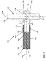
- Figure 2 shows the arrangement from Figure 1 in a sectional lateral view.
- the coolant chamber 113 has a rounded inner surface 126 which runs torically around the outer walling of the base body 122 and which makes it possible to conduct cooling liquid, which flows through the openings 118, in an annular manner around the base body 122 into the second fluidic terminal 110.
- a longitudinal axis 125 of the support 111 runs, according to the invention, not parallel to the first longitudinal axis 124, such that a space-saving yet flexible angled connector arrangement is produced.
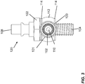
- Figures 3 to 6 illustrate the electrical connection unit 120 according to the embodiment shown in Fig. 1 , in various further views.
- Reference number Description 100 cable 101 insulator 102 electrically conductive material; metal mesh 103 cooling channel 104 first electrical terminal 106 second electrical terminal 108 first fluidic terminal 110 second fluidic terminal 111 support 112 ring coupler 113 coolant chamber 114; 114a, 114b sealing device; copper rings 115 interface 116 crimp region 118 opening 120 electrical connection unit 122 base body 124 first longitudinal axis 125 second longitudinal axis 126 inner surface 128 actuation unit 130 inner sleeve 132 outer sleeve
Landscapes
- Engineering & Computer Science (AREA)
- Power Engineering (AREA)
- Mechanical Engineering (AREA)
- Transportation (AREA)
- Microelectronics & Electronic Packaging (AREA)
- Physics & Mathematics (AREA)
- Thermal Sciences (AREA)
- Chemical & Material Sciences (AREA)
- Chemical Kinetics & Catalysis (AREA)
- Electrochemistry (AREA)
- General Chemical & Material Sciences (AREA)
- Secondary Cells (AREA)
- Connection Of Batteries Or Terminals (AREA)
- Connector Housings Or Holding Contact Members (AREA)
- Arrangement Or Mounting Of Propulsion Units For Vehicles (AREA)
Abstract
The present invention relates to an electrical connection unit with integrated cooling and a battery system, which has such a connection unit. In particular, the cooling can be achieved by means of a liquid coolant. An electrical connection unit (120) comprises a first electrical terminal (104) for contacting a first electrical component, a second electrical terminal (106) which is connected to an electrically conductive cable (100), wherein the electrical connection unit (120) establishes an electrical connection between the first electrical terminal (104) and the second electrical terminal (106), and a first fluidic terminal (108) for attaching a coolant source. The second electrical terminal (106), moreover, is formed as a second fluidic terminal (110), such that it connects a cooling channel (103), which is arranged on the cable (100) and through which a coolant for cooling the electrically conductive cable can flow, to the first fluidic terminal (108).
Description
- The present invention relates to an electrical connection unit with integrated cooling and to a battery system, which has such a connection unit. In particular, the cooling can be achieved by means of a liquid coolant.
- All electronic components, appliances and circuits generate excess heat, and thus require thermal management in order to improve reliability and prevent premature failure. In particular, in the case of the electrical connection of a battery system in a motor vehicle, there arise, at the electrical contacts of the battery, high currents and thus considerable amounts of heat which must be dissipated as quickly and efficiently as possible, in order to avoid dangerous overheating.
- There are various techniques for cooling electrical assemblies, for example air cooling using fans or thermoelectric cooling, which is based on the Peltier effect. Conventional air cooling systems with fans are limited in their capacity to dissipate heat. They are therefore suitable only to a limited extent for use with battery systems. It is substantially more efficient to discharge heat via a fluid, for example a cooling liquid such as water or an oil.
- By way of example, a device for cooling a plug connection is known from
DE 10 2015 221 571 A1 , which device is composed of a charging plug, a contact bushing, which is suitable for receiving the charging plug, a first electrical line which is connected to the contact bushing and a second electrical line which is connected to the charging plug, wherein the first electrical line has a first cavity and/or the second electrical line has a second cavity along the electrical line, via which a coolant is conducted. For example, a tube, which surrounds the charging cable, has a coolant flow through it. This coolant can be air, oil, water or another fluid suitable for dissipating heat. - This known arrangement has the disadvantage, however, that it offers no practicable solution for cooling at the contact point to a battery.
- There is therefore a requirement for means which permit a safe and efficient cooling of an electrical connection, and thus enhance and simplify the thermal management in particular directly at the contacts of a battery of an electric vehicle, both when charging the battery and when operating the vehicle.
- This problem is solved by the subject-matter of the independent claims. Advantageous developments of the present invention are the subject-matter of the subclaims.
- It is known to cool electrically conductive HF cables by means of a coolant liquid guided in the cable. By way of example, it is known from German examined and published application
DE 1160053 B that a copper hollow tube is arranged in a tube composed of rubber, such that the copper hollow tube serves to conduct current and the rubber tube serves to conduct the coolant further, the coolant simultaneously washing around the wires of the current conductor. - The inventors of the present invention have realised that the concept of liquid cooling of an electrical line can be adapted for use in a battery system, if the electrical terminal at the battery can be configured such that it can likewise have the cooling medium flow through it, at least partly. In particular, the present invention provides an electrical connection unit which, on the one hand, can be connected to a contact of a battery, and on the other hand to a corresponding external contact.
- According to the present invention, the electrical connection unit comprises a first electrical terminal for contacting a first electrical component, for example a battery, and a second electrical terminal, which is connected to an electrically conductive cable, wherein the electrical connection unit establishes an electrical connection between the first electrical terminal and the second electrical terminal. Furthermore, the electrical connection unit comprises a first fluidic terminal for attaching a coolant source. According to the present invention, the second electrical terminal, moreover, is formed as a second fluidic terminal, such that it connects a cooling channel, which is arranged on the cable and through which a coolant for cooling the electrically conductive cable can flow, to the first fluidic terminal.
- In this way, it can be achieved that an electrical attachment to a heat-generating component, such as a battery for example, can be cooled efficiently. In the process, it can be ensured that the coolant can be conducted as closely as possible to the actual contact point. The connection unit thus serves to attach to both the electrical current circuit and to the coolant circuit.
- In particular, if an electrically non-conductive coolant is used, electrical insulation of the electrically conductive material of the cable from the coolant can be dispensed with, as a result of which, on the one hand, the transition of heat is not impaired by an additional insulator, and on the other hand, the manufacture of the cable is simplified significantly. According to the present invention, the cable comprises an electrically conductive material, which forms a cavity which is surrounded by an insulator, wherein the cooling channel is formed in the interior of the cavity formed by the electrically conductive material.
- In order to allow the greatest possible flexibility of the position of the cable in relation to the first electrical component during the mounting of the electrical connection unit, the second electrical terminal is arranged at a ring coupler, wherein the ring coupler holds the second terminal rotatably around a longitudinal axis of the first electrical terminal. The rotatability of the ring coupler can be blocked after mounting on the first electrical component, for example, by a force fit of the inventive electrical connection unit. In other words, the rotatability exists only during the mounting, while the location of the cable is fixed in the finally mounted state. If the connection between the first electrical terminal and the first electrical component is releasable, it can be provided that the rotatability is allowed again mechanically by releasing the electrical connection.
- Ring support couplers for fluids are known, for example, from
EP0 646 748 B1 and are used if fluid lines, which can lie in any desired angular positions in relation to each other, have to be connected to each other. - Here, the basic form of the screw is a hollow cylinder, which is closed at the head end of the screw and open at the thread end. Furthermore, at the head end, the screw has two holes lying opposite each other. The ring terminal is composed of a ring which has a hole on one side, onto which a terminal support is placed, in such a way that the support points outwards in the radial direction. The ring terminal is plugged onto the hollow screw between two sealing rings. In this configuration, a liquid can be conducted around an angle.
- To attach a current line with integrated cooling system to a battery and a cooling circuit, there are, however, two requirements which cannot be fulfilled by the known solutions which focus exclusively on the fluidic connection. Firstly, it should be possible to screw the thread into the battery, and the screw should not be able to conduct liquid on the thread side, but rather current. Thus, the screw must not be hollow and open on the thread side, but rather should be solid. Secondly, it must be possible to attach a further tube, which is achieved according to the invention by means of the first fluidic terminal.
- In particular for use for contacting a battery, it is advantageous for steric reasons if the electrical connection unit has a base body with a first longitudinal axis, which runs along a plugging direction of the first fluidic terminal, wherein the plugging direction of the first fluidic terminal runs along the longitudinal axis of the first electrical terminal. In this way, the battery terminal, which corresponds to the first electrical terminal, lies opposite the coolant circuit terminal, as a result of which there is a clear spatial separation between coolant circuit and battery.
- According to an advantageous development of the present invention, the second electrical terminal has a second longitudinal axis, which does not run parallel to the plugging direction of the first fluidic terminal. In other words, the second longitudinal axis forms an angle not equal to 0° with the plugging direction. In this way, a releasable rapid coupler can be provided at the first fluidic terminal, for example, in order to allow a particularly simple and quick mounting of a coolant terminal, after the first electrical terminal is mounted on the contact of a battery, for example.
- Furthermore, it can be provided that the ring coupler forms a coolant chamber with the base body of the connection unit. In this way, the base body is washed around in the electrical contact region by the coolant both from inside and from outside. As a result, the heat produced is discharged even better.
- In particular, the first fluidic terminal can be connected fluidically to the coolant chamber of the ring coupler via at least one opening in the base body. By way of this opening, on the one hand the coolant flow is enabled, and on the other hand, however, sufficient current-carrying capacity and mechanical stability of the remaining walling of the base body is ensured. The coolant chamber is advantageously formed circulating around the base body, in such a way that the position of the at least one opening does not have to be correlated with the position of the second fluidic terminal, in order to allow an unhindered flow of coolant.
- In order to allow as high a throughput of coolant as possible, it is provided that a multiplicity of openings is arranged equidistantly at a circumference of the base body.
- In operation, the liquid-cooled electrical connection unit must be fluidically sealed, so that no liquid can escape. In accordance with the present invention, this is achieved advantageously by means of at least one electrically conductive sealing device. By way of example, it can be provided that at least one copper seal is fitted at the interface between the base body and the ring coupler. The advantage of such a metallic seal is that, on the one hand, the current-carrying capacity is increased, and on the other hand, that a durable and mechanically stable seal can be ensured, even under demanding environmental conditions.
- According to an advantageous development of the present invention, the cable is connected to the second electrical terminal by means of a crimp connection. The advantage of such a crimp connection is that a stable mechanical and electrical connection with high current-carrying capacity can be established, even under high thermal loads. To establish the crimp connection, the second electrical terminal can have an inner sleeve and an outer sleeve, which are arranged concentrically with respect to each other and to a longitudinal axis of the second electrical terminal. The substantially tubular cable is introduced into an intermediate space between the two sleeves, and the outer sleeve is pressed onto the inner sleeve, in order to establish an electrical connection between the inner sleeve and the electrical conductor of the cable. Here, it can also be provided that the outer sleeve has inwardly directed tongues, which can penetrate the insulation of the cable in order to contact the electrical conductor. In this way, the current-carrying capacity is increased once again. Advantageously, by way of the crimp connection onto the electrically insulating sheath of the cable, the fluidic sealing also takes place between the fluid-filled cable and the second electrical terminal, which, according to the invention, also functions as a fluidic terminal.
- A particularly stable and easily re-releasable electrical connection which is able to carry current and which is in particular for contacting a battery of a motor vehicle can be established, if the first electrical terminal is formed as a screw thread.
- The advantages of the present invention take effect in particular if the inventive connection unit is used in a battery system of a motor vehicle, for example. Accordingly, the present invention moreover relates to a battery system having at least one electrical contact, wherein the electrical contact is connected to the first electrical terminal of a connection unit according to the present invention, and wherein the first fluidic terminal is attached to a coolant reservoir of the battery system.
- Advantageously, provided that the inventive electrical connection unit has a ring coupler, this ring coupler is mechanically fixed by way of the connection between the electrical contact and the first electrical terminal. In this way, it can be achieved that the dissipation position of the cable can be adjusted according to the geometrical conditions during the mounting, and then this position is fixed securely in operation.
- To better understand the present invention, it is explained in greater detail using the exemplary embodiments depicted in the following figures. Identical parts here are provided with identical reference numbers and identical component names. Furthermore, some features or combinations of features from the different embodiments shown and described may also represent solutions which are independent, inventive or in accordance with the invention per se.
- In the drawings:
- Figure 1
- shows a schematic perspective sectional view of an electrical connection unit according to an advantageous embodiment of the present invention;
- Figure 2
- shows a lateral sectional view of the electrical connection unit from
Figure 1 ; - Figure 3
- shows an unopened side view of the electrical connection unit from
Figure 1 ; - Figure 4
- shows a further unopened side view of the electrical connection unit from
Figure 1 ; - Figure 5
- shows an unopened perspective view of the electrical connection unit from
Figure 1 ; - Figure 6
- shows a plan view of the electrical connection unit from
Figure 1 . - The present invention is explained in greater detail hereinbelow with reference to the figures, and firstly with reference to
Figure 1 . -
Figure 1 shows anelectrical connection unit 120, which is suitable for electrically contacting a battery contact (not shown in the figures). For this purpose, theelectrical connection unit 120 has a firstelectrical terminal 104, which is formed as a screw connection in the embodiment shown. For a person skilled in the art, however, it is clear that other configurations of the first electrical terminal, such as plug connectors or press-in connections for example, can also be used. - The first
electrical terminal 104 is part of abase body 122, which extends along a firstlongitudinal axis 124. Thebase body 122 is partly hollow and has afirst fluidic terminal 108 for attaching a coolant line (not shown in the figures). In the embodiment shown, thefirst fluidic terminal 108 is configured as a rapid coupler. In this way, theelectrical connection unit 120 can be attached quickly and releasably, for example, to the vehicle-internal cooling circuit of a battery. - In accordance with the present invention, a second
electrical terminal 106 is provided on theelectrical connection unit 120, said terminal being connected to acable 100 and providing both the electrical contacting to the electricallyconductive material 102 of the cable as well as the fluidic contacting. According to the invention, thecable 100 has an electrically insulatingsheath 101, in the interior of which an electricallyconductive material 102 is arranged. In this way, the cable forms acooling channel 103 in its interior, through which coolant can flow. According to an advantageous embodiment, thecable 100 comprises aTeflon tube 101 on the outside and ametal mesh 102 on the inside. In order to achieve optimum conductivity, copper is used as the metal. The conductivity of this construction can be increased, by using several layers of the copper mesh. In order to cool this conductor, a coolant is conducted through the cavity formed by thecopper mesh 102. By way of the fabric structure, a very large interface can be achieved between the copper and the coolant, as a result of which efficient cooling is made possible. - In accordance with the present invention, the
second fluidic terminal 110 is arranged on aring coupler 112, so that said terminal can rotate around theaxis 124. This arrangement allows a significantly facilitated mounting of theelectrical connection unit 120 according to the invention. - It is of course clear, however, to a person skilled in the art that the combined second electrical and
fluidic terminal base body 122. - The
base body 122 hasopenings 118, which are arranged equidistantly around its circumference in order to allow coolant to flow into thecoolant chamber 113 formed by the ring coupler. Here, the coolant flow is directed in a fluidically advantageous manner, in such a way that it runs from thefirst fluidic terminal 108 through theopenings 118 to thesecond fluidic terminal 110, and enters into the electricallyconductive cooling channel 103 of thecable 100. Of course, this direction of flow is not obligatory, however. - The arrangement according to the invention makes it possible for both the
cable 100 and also the immediate environment of theconductors - In the embodiment shown, the
interfaces 115 between thebase body 122 and thering coupler 112 are sealed by two copper rings 114. In the non-mounted state, the support of thering coupler 112, which forms the secondelectrical terminal 106 and thesecond fluidic terminal 110, can still rotate around thelongitudinal axis 124 and thecompactions 114 still have no sealing function. As soon as the screw connection of the firstelectrical terminal 104, however, is mounted with sufficient firmness on a mating contact carrier (not shown in the figures), thefirst copper seal 114a lies on a counter bearing not depicted in the figures. - By way of the forces acting in the axial direction along the
longitudinal axis 124, the copper seals 114 are pressed against thering coupler 112. Consequently, on the one hand thering coupler 112 can no longer rotate around thelongitudinal axis 124. On the other hand, theinterfaces 115 with thebase body 122 are sealed in a liquid-tight manner. In order to facilitate the mounting of the inventiveelectrical connection unit 120, anactuation unit 128 similar to a screw nut is arranged on thebase body 122. Thus, theelectrical connection unit 120 can be mounted using conventional mounting tools, for example on a battery. Provided that the first fluidic terminal is still open, theactuation unit 128 is easily accessible for a tool and thebase body 122 can be screwed securely, without thesupport 111, which forms the second electrical andfluidic terminal ring coupler 112 become jammed and no longer able to be rotated. - Advantageously, the
cable 100 can thus already be mounted on the secondelectrical terminal 106 in the factory. - According to the embodiment shown, the
support 111 is equipped with aninner sleeve 130 and anouter sleeve 132 for this purpose. In the radial direction, a circumferential gap is formed between theinner sleeve 130 and theouter sleeve 132, into which gap thecable 100 is inserted. - In a
crimp region 116, theouter sleeve 132 is pressed radially inwards in the direction of thecable 100 and theinner sleeve 130. As a result, the electricallyconductive material 102 of thecable 100 is pressed onto the outside of theinner sleeve 130, such that an electrical contacting takes place. Moreover, thecrimp region 116 also forms a radially circumferential press-fit connection between theouter sleeve 132 and the electrically insulatingsheath 101 of thecable 100. Thus, in a particularly simple manner, the mechanical fixing of thecable 100 and a fluidic seal between thesupport 111 and thefluid channel 103 are established. -
Figure 2 shows the arrangement fromFigure 1 in a sectional lateral view. As can be seen from this depiction, thecoolant chamber 113 has a roundedinner surface 126 which runs torically around the outer walling of thebase body 122 and which makes it possible to conduct cooling liquid, which flows through theopenings 118, in an annular manner around thebase body 122 into thesecond fluidic terminal 110. Alongitudinal axis 125 of thesupport 111 runs, according to the invention, not parallel to the firstlongitudinal axis 124, such that a space-saving yet flexible angled connector arrangement is produced. -
Figures 3 to 6 illustrate theelectrical connection unit 120 according to the embodiment shown inFig. 1 , in various further views.List of reference symbols: Reference number Description 100 cable 101 insulator 102 electrically conductive material; metal mesh 103 cooling channel 104 first electrical terminal 106 second electrical terminal 108 first fluidic terminal 110 second fluidic terminal 111 support 112 ring coupler 113 coolant chamber 114; 114a, 114b sealing device; copper rings 115 interface 116 crimp region 118 opening 120 electrical connection unit 122 base body 124 first longitudinal axis 125 second longitudinal axis 126 inner surface 128 actuation unit 130 inner sleeve 132 outer sleeve
Claims (15)
- An electrical connection unit, comprising
a first electrical terminal (104) for contacting a first electrical component,
a second electrical terminal (106), which is connected to an electrically conductive cable (100), wherein the electrical connection unit (120) establishes an electrical connection between the first electrical terminal (104) and the second electrical terminal (106), and
a first fluidic terminal (108) for attaching a coolant source,
wherein the second electrical terminal (106), moreover, is formed as a second fluidic terminal (110), such that it connects a cooling channel (103), which is arranged on the cable (100) and through which a coolant for cooling the electrically conductive cable can flow, to the first fluidic terminal (108). - The electrical connection unit according to Claim 1, wherein the cable (100) comprises an electrically conductive material (102), which forms a cavity which is surrounded by an insulator (101), wherein the cooling channel (103) is formed in the interior of the cavity formed by the electrically conductive material (102).
- The electrical connection unit according to any one of Claims 1 or 2, wherein the second electrical terminal (106) is arranged at a ring coupler (112) and wherein the ring coupler (112) holds the second terminal (106) rotatably around a longitudinal axis of the first electrical terminal (104).
- The electrical connection unit according to Claim 3, wherein the connection unit (120) has a base body (122) with a first longitudinal axis, which runs along a plugging direction of the first fluidic terminal (108), and wherein the plugging direction of the first fluidic terminal (108) runs along the longitudinal axis of the first electrical terminal (104).
- The electrical connection unit according to Claim 4, wherein the second electrical terminal (106) has a second longitudinal axis, which does not run parallel to the plugging direction of the first fluidic terminal (108).
- The electrical connection unit according to any one of Claims 3 to 5, wherein the ring coupler (112) forms a coolant chamber (113) with the base body (122) of the connection unit (120).
- The electrical connection unit according to Claim 6, wherein the first fluidic terminal (108) is fluidically connected to the coolant chamber (113) of the ring coupler (112) via at least one opening (118) in the base body (122).
- The electrical connection unit according to Claim 7, wherein a multiplicity of openings (118) is arranged equidistantly at a circumference of the base body (122).
- The electrical connection unit according to any one of Claims 3 to 8, wherein an interface between the base body (122) and the ring coupler (112) can be sealed by means of at least one electrically conductive sealing device (114).
- The electrical connection unit according to Claim 9, wherein the at least one electrically conductive sealing device (114) comprises a copper ring.
- The electrical connection unit according to any one of Claims 1 to 10, wherein the cable (100) is connected to the second electrical terminal (106) by means of a crimp connection (116).
- The electrical connection unit according to Claim 11, wherein the cable (100) has an insulating sheath (101)for electrically insulating the cable (100) and for fluidically sealing at the crimp connection (116).
- The electrical connection unit according to any one of the preceding claims, wherein the first electrical terminal (104) is formed as a screw thread.
- A battery system having at least one electrical contact, wherein the electrical contact is connected to the first electrical terminal (104) of a connection unit (120) according to any one of the preceding claims, and wherein the first fluidic terminal (108) is attached to a coolant reservoir of the battery system.
- The battery system according to Claims 3 and 14, wherein the ring coupler (112) is mechanically fixed by way of the connection between the electrical contact and the first electrical terminal (104).
Applications Claiming Priority (1)
| Application Number | Priority Date | Filing Date | Title |
|---|---|---|---|
| DE102018202128.7A DE102018202128A1 (en) | 2018-02-12 | 2018-02-12 | Electrical connection unit and battery system |
Publications (1)
| Publication Number | Publication Date |
|---|---|
| EP3525296A1 true EP3525296A1 (en) | 2019-08-14 |
Family
ID=65324214
Family Applications (1)
| Application Number | Title | Priority Date | Filing Date |
|---|---|---|---|
| EP19155463.3A Withdrawn EP3525296A1 (en) | 2018-02-12 | 2019-02-05 | Electrical connection unit and battery system |
Country Status (6)
| Country | Link |
|---|---|
| US (1) | US20190252094A1 (en) |
| EP (1) | EP3525296A1 (en) |
| JP (1) | JP2019153578A (en) |
| KR (1) | KR20190098065A (en) |
| CN (1) | CN110165441A (en) |
| DE (1) | DE102018202128A1 (en) |
Cited By (1)
| Publication number | Priority date | Publication date | Assignee | Title |
|---|---|---|---|---|
| EP4287409A1 (en) * | 2022-06-03 | 2023-12-06 | Aptiv Technologies Limited | Electrical connector for connecting high voltage power cable comprising electrical conductor to electrical terminal |
Families Citing this family (11)
| Publication number | Priority date | Publication date | Assignee | Title |
|---|---|---|---|---|
| CH715611B1 (en) * | 2018-12-05 | 2022-05-13 | BRUGG eConnect AG | Connection element for the electrical connection of a fluid-coolable individual line, fluid-coolable individual line unit and charging cable. |
| US11848459B2 (en) * | 2019-02-26 | 2023-12-19 | Ford Global Technologies, Llc | Barrier seal assemblies for sealing vehicle electrical housings |
| CN110696651B (en) * | 2019-09-27 | 2025-04-08 | 中航光电科技股份有限公司 | A charging terminal liquid cooling structure |
| JP7431042B2 (en) * | 2020-01-15 | 2024-02-14 | 東海旅客鉄道株式会社 | Electric wire with socket, connection structure of electric wire, connection method of electric wire, and manufacturing method of electric wire with socket |
| DE102020116699A1 (en) | 2020-06-24 | 2021-12-30 | Faurecia Emissions Control Technologies, Germany Gmbh | Connector for connecting an electrical pole of a battery cell or a cell module to a busbar and battery system |
| DE102021108761B3 (en) * | 2021-04-08 | 2022-01-13 | Dr. Ing. H.C. F. Porsche Aktiengesellschaft | High voltage battery component and method of assembling a high voltage battery component |
| DE102021208239A1 (en) | 2021-07-29 | 2023-02-02 | Volkswagen Aktiengesellschaft | Electrical interface with thermal decoupling |
| CN113883347B (en) * | 2021-10-09 | 2023-03-14 | 中国电子科技集团公司第十四研究所 | Special-shaped section water pipe adapter with shielding effect and using method |
| FR3144706B1 (en) * | 2022-12-28 | 2025-05-16 | Renault Sas | Power connection support device for battery, especially for electric vehicle battery |
| DE102023111650A1 (en) * | 2023-05-04 | 2024-11-07 | Te Connectivity Solutions Gmbh | housing part for a hybrid connector |
| DE102024112280A1 (en) | 2024-05-02 | 2025-11-06 | Bayerische Motoren Werke Aktiengesellschaft | Connection device with fluid connection and equipotential bonding |
Citations (4)
| Publication number | Priority date | Publication date | Assignee | Title |
|---|---|---|---|---|
| DE1160053B (en) | 1962-05-16 | 1963-12-27 | Philips Patentverwaltung | Connection element for waveguide cable |
| EP0646748B1 (en) | 1993-09-30 | 1997-06-18 | Cohnen Beteiligungs-GmbH & Co. KG | "Banjo" type pipe joint |
| DE19921310A1 (en) * | 1999-05-07 | 2000-11-09 | Leoni Bordnetz Sys Gmbh & Co | Electrical device, especially electric drive for motor vehicle, has thermally conducting central cooling channel extending in longitudinal direction of cable and carrying cooling medium |
| DE102015221571A1 (en) | 2015-11-04 | 2017-05-04 | Robert Bosch Gmbh | Device for cooling an electrical connector |
Family Cites Families (24)
| Publication number | Priority date | Publication date | Assignee | Title |
|---|---|---|---|---|
| US608852A (en) * | 1898-08-09 | Bight angle swivel connection | ||
| SE7409869L (en) * | 1973-08-20 | 1975-02-21 | Legris France Sa | |
| DE2610775A1 (en) * | 1976-03-15 | 1977-09-22 | Ermeto Armaturen Gmbh | SWIVEL COUPLING FOR PIPE CONNECTION |
| JPH038869Y2 (en) * | 1985-01-28 | 1991-03-05 | ||
| IT211623Z2 (en) * | 1986-11-03 | 1989-04-07 | Murray Europ | FITTING FOR FLUIDS. |
| IT1223253B (en) * | 1987-12-10 | 1990-09-19 | Murray Europ Spa | FITTING FOR FLUIDS |
| US5004865A (en) * | 1989-10-10 | 1991-04-02 | Krupnicki Theodore A | Splicing device for fluid-cooled electric cables |
| US5403042A (en) * | 1993-12-09 | 1995-04-04 | Negron; Steve A. | Transmission fluid cooler line flushing adapter and method |
| US6086112A (en) * | 1998-01-13 | 2000-07-11 | Saint-Gobain Performance Plastic Corporation | Fluid swivel coupling device |
| US6260571B1 (en) * | 1998-12-14 | 2001-07-17 | Survival Engineering, Inc. | Inflation valve assembly for liferafts |
| US6685232B2 (en) * | 2001-09-06 | 2004-02-03 | Franklin Fastener Company | Banjo clip for flange head flow bolt |
| US6851723B2 (en) * | 2001-09-28 | 2005-02-08 | Usui Kokusai Sangyo Kaisha, Ltd. | Ring joint, connection structure for connecting piping and ring joint, and method of connecting ring joint and piping |
| DE10239777A1 (en) * | 2002-08-29 | 2004-03-18 | Robert Bosch Gmbh | Device for venting a conveyor unit |
| US7226088B2 (en) * | 2004-05-18 | 2007-06-05 | Dayco Products, Llc | Banjo fitting |
| US7988201B2 (en) * | 2007-05-10 | 2011-08-02 | GM Global Technology Operations LLC | Fluid coupling assembly having a rotatable coupling |
| TW200819666A (en) * | 2007-12-07 | 2008-05-01 | Zhong-Zhi Wei | Quick pneumatic/hydraulic joint |
| US9150275B2 (en) * | 2009-12-17 | 2015-10-06 | Shimano Inc. | Hydraulic connector arrangement |
| US9007109B2 (en) * | 2013-05-07 | 2015-04-14 | Nvidia Corporation | Automatic loop-bandwidth calibration for a digital phased-locked loop |
| JP5958420B2 (en) * | 2013-05-29 | 2016-08-02 | トヨタ自動車株式会社 | Battery drying apparatus and battery manufacturing method |
| DE102015100347A1 (en) * | 2015-01-12 | 2016-07-14 | Phoenix Contact E-Mobility Gmbh | Electrical connection body for a charging plug and / or a charging socket, charging plug and charging station for delivering electrical energy to a receiver of electrical energy |
| DE102015119338B4 (en) * | 2015-11-10 | 2018-01-25 | Phoenix Contact E-Mobility Gmbh | Contact assembly and connector part e.g. for a charging plug |
| DE102016117011A1 (en) * | 2016-09-09 | 2018-03-15 | Itt Manufacturing Enterprises Llc | Electrically conductive contact element for an electrical connector |
| DE102016224014B4 (en) * | 2016-12-02 | 2021-09-23 | Bayerische Motoren Werke Aktiengesellschaft | Tensioning device and method for introducing a pretensioning into a tubular hollow profile |
| EP3401955B1 (en) * | 2017-05-12 | 2021-06-30 | ODU GmbH & Co. KG | Plug-in connector with a cooling jacket |
-
2018
- 2018-02-12 DE DE102018202128.7A patent/DE102018202128A1/en not_active Withdrawn
-
2019
- 2019-02-05 EP EP19155463.3A patent/EP3525296A1/en not_active Withdrawn
- 2019-02-07 JP JP2019020230A patent/JP2019153578A/en active Pending
- 2019-02-11 US US16/272,387 patent/US20190252094A1/en not_active Abandoned
- 2019-02-11 KR KR1020190015676A patent/KR20190098065A/en not_active Withdrawn
- 2019-02-12 CN CN201910110958.9A patent/CN110165441A/en active Pending
Patent Citations (4)
| Publication number | Priority date | Publication date | Assignee | Title |
|---|---|---|---|---|
| DE1160053B (en) | 1962-05-16 | 1963-12-27 | Philips Patentverwaltung | Connection element for waveguide cable |
| EP0646748B1 (en) | 1993-09-30 | 1997-06-18 | Cohnen Beteiligungs-GmbH & Co. KG | "Banjo" type pipe joint |
| DE19921310A1 (en) * | 1999-05-07 | 2000-11-09 | Leoni Bordnetz Sys Gmbh & Co | Electrical device, especially electric drive for motor vehicle, has thermally conducting central cooling channel extending in longitudinal direction of cable and carrying cooling medium |
| DE102015221571A1 (en) | 2015-11-04 | 2017-05-04 | Robert Bosch Gmbh | Device for cooling an electrical connector |
Cited By (1)
| Publication number | Priority date | Publication date | Assignee | Title |
|---|---|---|---|---|
| EP4287409A1 (en) * | 2022-06-03 | 2023-12-06 | Aptiv Technologies Limited | Electrical connector for connecting high voltage power cable comprising electrical conductor to electrical terminal |
Also Published As
| Publication number | Publication date |
|---|---|
| KR20190098065A (en) | 2019-08-21 |
| JP2019153578A (en) | 2019-09-12 |
| CN110165441A (en) | 2019-08-23 |
| DE102018202128A1 (en) | 2019-08-14 |
| US20190252094A1 (en) | 2019-08-15 |
Similar Documents
| Publication | Publication Date | Title |
|---|---|---|
| US20190252094A1 (en) | Electrical Connection Unit and Battery System | |
| KR102508729B1 (en) | Electrically conductive contact elements for electrical plug connectors | |
| JP4522517B2 (en) | Electrostatic chuck connector and its combination | |
| CN109075478B (en) | Plug connection with cooled contact elements | |
| EP3379655B1 (en) | Electrical connector and electrical connection arrangement comprising an electrical connector | |
| CN107681314B (en) | Liquid-cooled cable plug-in structure and charging connector | |
| US11811160B2 (en) | Plug contact for an electrical charging connector | |
| US12154706B2 (en) | Power cable assembly for a power distribution system having an integrated cooling system | |
| US11718192B2 (en) | Protective earthing and cooling system for a charging plug, charging plug and charging station for discharging electric energy to a recipient of electric energy | |
| CN104242084B (en) | Nozzle for switching device, the switching device with nozzle and its method | |
| CN114786988A (en) | Contact arrangement for a plug connection, i.e. a charging plug, comprising a cooling device | |
| CN214267373U (en) | Liquid-cooled structure of a charging base and liquid-cooled charging base | |
| CN110696651B (en) | A charging terminal liquid cooling structure | |
| AU2013262011A1 (en) | Underwater electrical connection | |
| RU2016147353A (en) | CONSUMABLE CARTRIDGE FOR PLASMA ARC SYSTEM | |
| JP6565638B2 (en) | Cable connection device | |
| CN113799628B (en) | Liquid cooling terminal heat radiation structure for charging | |
| CN113169529B (en) | Bus bar connecting device | |
| BR102016003840A2 (en) | multi-piece cover for detachable connector | |
| US20200406406A1 (en) | Electrical connection element | |
| JP2018038134A (en) | Cable connection device | |
| TW200908468A (en) | Trailing end connecting portion of connecting member, and connecting portion of electric device | |
| CN112838401B (en) | Charging terminal assembly | |
| JP2018038135A (en) | Cable connection device and power cable | |
| EP3912848A1 (en) | Cooling device for a connector element and connector element for high-voltage applications |
Legal Events
| Date | Code | Title | Description |
|---|---|---|---|
| PUAI | Public reference made under article 153(3) epc to a published international application that has entered the european phase |
Free format text: ORIGINAL CODE: 0009012 |
|
| AK | Designated contracting states |
Kind code of ref document: A1 Designated state(s): AL AT BE BG CH CY CZ DE DK EE ES FI FR GB GR HR HU IE IS IT LI LT LU LV MC MK MT NL NO PL PT RO RS SE SI SK SM TR |
|
| AX | Request for extension of the european patent |
Extension state: BA ME |
|
| STAA | Information on the status of an ep patent application or granted ep patent |
Free format text: STATUS: THE APPLICATION IS DEEMED TO BE WITHDRAWN |
|
| 18D | Application deemed to be withdrawn |
Effective date: 20200215 |